US8992582B1 - Fixation devices and method - Google Patents
Fixation devices and methodDownload PDFInfo
- Publication number
- US8992582B1 US8992582B1US13/975,588US201313975588AUS8992582B1US 8992582 B1US8992582 B1US 8992582B1US 201313975588 AUS201313975588 AUS 201313975588AUS 8992582 B1US8992582 B1US 8992582B1
- Authority
- US
- United States
- Prior art keywords
- plate
- bone
- spacer
- bone screw
- screw
- Prior art date
- Legal status (The legal status is an assumption and is not a legal conclusion. Google has not performed a legal analysis and makes no representation as to the accuracy of the status listed.)
- Active, expires
Links
Images


Classifications
- A—HUMAN NECESSITIES
- A61—MEDICAL OR VETERINARY SCIENCE; HYGIENE
- A61B—DIAGNOSIS; SURGERY; IDENTIFICATION
- A61B17/00—Surgical instruments, devices or methods
- A61B17/56—Surgical instruments or methods for treatment of bones or joints; Devices specially adapted therefor
- A61B17/58—Surgical instruments or methods for treatment of bones or joints; Devices specially adapted therefor for osteosynthesis, e.g. bone plates, screws or setting implements
- A61B17/68—Internal fixation devices, including fasteners and spinal fixators, even if a part thereof projects from the skin
- A61B17/80—Cortical plates, i.e. bone plates; Instruments for holding or positioning cortical plates, or for compressing bones attached to cortical plates
- A61B17/8061—Cortical plates, i.e. bone plates; Instruments for holding or positioning cortical plates, or for compressing bones attached to cortical plates specially adapted for particular bones
- A61B17/8071—Cortical plates, i.e. bone plates; Instruments for holding or positioning cortical plates, or for compressing bones attached to cortical plates specially adapted for particular bones for the jaw
- A—HUMAN NECESSITIES
- A61—MEDICAL OR VETERINARY SCIENCE; HYGIENE
- A61B—DIAGNOSIS; SURGERY; IDENTIFICATION
- A61B17/00—Surgical instruments, devices or methods
- A61B17/56—Surgical instruments or methods for treatment of bones or joints; Devices specially adapted therefor
- A61B17/58—Surgical instruments or methods for treatment of bones or joints; Devices specially adapted therefor for osteosynthesis, e.g. bone plates, screws or setting implements
- A61B17/68—Internal fixation devices, including fasteners and spinal fixators, even if a part thereof projects from the skin
- A61B17/80—Cortical plates, i.e. bone plates; Instruments for holding or positioning cortical plates, or for compressing bones attached to cortical plates
- A61B17/8028—Cushions, i.e. elements forming interface between bone plate and bone
Definitions
- IMFintermaxillary fixation or stabilization
- Wiring techniquesrepresent the earliest methods of securing the maxillary and mandibular jaw.
- the methodinvolves utilizing metallic wires that are placed around one or more teeth at their base and then twisted using various methods to secure the teeth.
- the wirescan be used in pairs or in greater multiples along the span of the dental arch forming a series, or, alternatively, a single strand of wire may incorporate a plurality of teeth.
- the methods of placing and twisting the wire so describedachieve a secured fixation.
- the ultimate combination of the aforementioned methodsinvolves the upper and lower arches secured along their respective lengths, and subsequently the maxillary and mandible jaws secured to one another with ligatures, thus accomplishing IMF.
- the techniqueis tedious and time consuming.
- the wirescan also interfere with dental hygiene.
- arch barsin combination with wiring.
- a metal, or sometimes plastic, baris shaped to approximate the curvature of the maxilla or mandible. Ligatures are wrapped around the teeth and over the bar, and then twisted onto the bar.
- arch barshave a plurality of hooks or tabs facing in the same direction. If two arch bars are used, the hooks or tabs of each one are placed in opposing directions so that ligatures may securely affix the jaws together.
- the semi-rigid arch barsspan the dental arch providing stability along the upper end of the maxillary or mandible jaw even when a fracture or fractures exist between teeth, while the plurality of hooks allows placement of ligatures between the jaws at varying angles and lengths to allow various combinations of beneficial tension vectors.
- arch barsrequire significant time to secure in place and tend to interfere with dental hygiene. Another limitation of arch bars is that they may not provide satisfactory fixation in a fully or partially edentulous patient. Furthermore, the wire ligatures themselves are painful and frequently must be adjusted by the treating physician or other medical professional. Finally, removal of the arch bars may be difficult and carries with it the increased risk of dental injury and the need for operative anesthesia.
- ligaturesmay be secured to contiguous sets of screws in varying combinations to provide IMF. This technique is limited by an absence of overall structural stability which may be necessary in some instances, e.g., when a patient has fractures around the teeth.
- One aspect of the present inventionmay be a method of fixation comprising the steps of placing a portion of a spacer adjacent to a first bone at a first location, placing a first plate so that the portion of the spacer may be located between the first plate and the first bone, inserting a first bone screw through the first plate at the first location while the portion of the spacer remains between the first plate and the first bone, and removing the portion of the spacer from between the first plate and the first bone so that the first plate remains spaced apart from the first bone.
- the first bonemay be a maxilla and the method may further include the step of bending the first plate to approximate the shape of the maxilla.
- the first bonemay be a mandible and the method may further include the step of bending the first plate to approximate the shape of the mandible.
- the portion of the spacer placed adjacent to the first bone at the first locationmay include tines having tapered distal ends.
- the first bone screwmay be inserted through the tines.
- the first bone screwmay be inserted through a first attachment loop of the first plate.
- the first attachment loopmay be bent with respect to the remainder of the first plate.
- a portion of the spacermay be placed adjacent to the first bone at a second location and a second bone screw may be inserted through the first plate at the second location while the portion of the spacer remains between the first plate and the first bone.
- the portion of the spacer placed adjacent to the first bone at the second locationmay include tines having tapered distal ends.
- the second bone screwmay be inserted through the tines.
- the second bone screwmay be inserted through a second attachment loop of the first plate. And in still further embodiments, the second attachment loop may be bent with respect to the remainder of the first plate.
- the step of inserting the first bone screwmay include fixing a portion of the first bone screw to the first plate.
- the first bone screwmay include a first bone screw head formed of a hard material and the first plate may include a portion formed of a soft material and insertion of the first bone screw may result in the first bone screw head deforming the portion of the first plate.
- the first bonemay be a maxilla and the method may further comprise the steps of placing a portion of the spacer adjacent to a second bone at a second location, the second bone being the mandible, placing a second plate so that the portion of the spacer may be located between the second plate and the second bone, inserting a second bone screw through the second plate at the second location while the portion of the spacer remains between the second plate and the second bone, and removing the portion of the spacer from between the second plate and the second bone so that the second plate remains spaced apart from the second bone.
- the present inventionmay comprise a plate system comprising of a first bone screw further comprising a countersunk preformed thread and therebelow a self-tapping screw shank, wherein the countersunk preformed thread of the first bone screw may be fixed to a first plate of semi-rigid material comprising a countersunk opening wherein the countersunk preformed thread may be located in the opening such that the cavities of the preformed thread are filled with plate material, wherein the self-tapping screw shank of the first bone screw may be embedded and fixed in a bone to a certain depth, and wherein a space may exist between the plate and the adjacent bone.
- connection between the plate and the bone screwmay be supported by friction such that the bone screw does not back out of the plate when subject to forces.
- the platemay comprise a first attachment loop, connected to the remainder of the plate as a single material and oriented transverse to the plate length.
- the first attachment loopmay be bent relative to the remainder of the plate.
- the platemay further comprise a second attachment loop, connected to the remainder of the plate as a single material and oriented transverse to the plate length.
- the bone screwmay comprise a button head and cross-recess screw drive.
- the screw shankmay be self-drilling.
- the first bone screwmay be embedded and fixed in a maxilla.
- a second bone screwmay be inserted through a second plate system and embedded and fixed in a mandible.
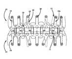
- FIG. 1is a perspective view of a full dental arch having first and second plates and a plurality of screws in place across the dentition, according to one embodiment.
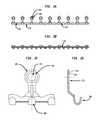
- FIG. 2Ais a frontal view of the first plate shown in FIG. 1 prior to bending to approximate the shape of a mandible or maxilla.
- FIG. 2Bis a top view of the first plate shown in FIG. 1 prior to bending to approximate the shape of the mandible or maxilla.
- FIG. 2Cis a partial frontal view of the first plate shown in FIG. 1 .
- FIG. 2Dis a cross-section of the first plate shown in FIG. 1 at an attachment loop.
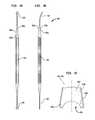
- FIG. 3Ais a frontal view of a bone screw shown in FIG. 1 .
- FIG. 3Bis a cross section of the bone screw of FIG. 3A along the longitudinal axis.
- FIG. 3Cis a top view of the bone screw of FIG. 3A .
- FIG. 4Ais a top view of a spacer for use in placing the plates and screws of FIG. 1 .
- FIG. 4Bis a side view of the spacer of FIG. 4A .
- FIG. 4Cis a partial top view of the spacer of FIG. 4A .
- FIGS. 1-4Cdepict components usable in methods including, but not limited to, treatment of human maxillary and mandibular fractures, restoration and fixation of dental occlusion, and maxillary and/or mandibular reconstruction with or without bone grafts.
- various components discussed hereinare directed toward a use in connection with fractured maxillary or mandible bones, such components may be modified (if necessary) to have applicability in the repair of fractures in other bones in human or animal bodies.
- Those of ordinary skill in the artwould readily recognize that such components, although discussed in connection with a single purpose, have applicability for other purposes in the orthopedic field.
- a plate system 100includes a plate 110 having a plurality of stems 140 , a plurality of attachment loops 120 at the distal ends of the stems 140 , and a plurality of hooks 130 .
- stem 140may be rigid or bendable
- plate 110may likewise be bendable so as to be capable of approximating the shape of a maxillary or mandibular arch, as shown in FIG. 1 .
- Plate 110may be constructed from a variety of materials suitable for implantation in the body, e.g., metals such as stainless steel or titanium and polymers such as PEEK.
- attachment loops 120 and hooks 130may be a single material formed integral with the remainder of plate 110 . In other embodiments, attachment loops 120 and hooks 130 may be made from separate material, as disclosed in the '850 patent. Attachment loops 120 provide a location at which plate 110 may be secured to a bone fragment such as a maxilla or a mandible using a bone screw or other fastener, but are not limited to such application. Attachment loops 120 are preferably evenly spaced along the length of the plate 110 .
- attachment loops 120include a circular opening 121 , although, in other embodiments, the opening may be of any shape.
- the cross-sectional view of FIG. 2Dfurther illustrates that attachment loop 120 includes a top countersunk 122 which decreases toward the bottom of the hole to form a lip 124 , also disclosed in FIG. 2A of the '562 patent, with alternative embodiments as disclosed in FIGS. 2B-2I of the '562 patent.
- Lip 124may be designed so as to allow for a rigid connection with a bone screw, like the bone screws discussed below.
- lip 124being formed of a material which is softer than a material of such bone screw.
- One such type of designis currently offered in various bone plates offered by Stryker Trauma GmbH under the tradenames, VARIAX® and SMARTLOCK®.
- the '562 patentdiscloses a similar screw fixation concept.
- Stems 140are preferably positioned on plate 110 so that any screw placed through attachment loops 120 are positioned between roots 150 of the teeth (shown in phantom in FIG. 1 ). For any stem that does not align between the apparent root locations, the bendability of such stem may allow for the avoidance of root 150 . This characteristic is illustrated in FIG. 1 , where stem 140 a is so adjusted. Adjustments of the stem 140 position may also be made as desired by the treating surgeon or other medical professional.
- hooks 130are formed integral with the remainder of plate 110 . This construction is shown more specifically in FIGS. 2A-2D .
- a securing wire 170is shown in FIG. 1 in engagement with hooks 130 for the purpose of IMF. More particularly, IMF is accomplished through use of securing wire 170 attached to the plate 110 by placing securing wire around opposing hooks 130 , i.e. connecting plate system 100 with plate system 200 , and by twisting the ends of the wire around each other. This may involve connecting single hooks 130 on each side, or connections in greater multiples, such as over two hooks on the maxillary plate 110 and two hooks on the mandible plate 210 .
- FIG. 1illustrates an embodiment that uses securing wire for IMF, however, other suitable ligatures that are known to those of skill in the art may be used in the place of securing wire.
- suitable ligaturesinclude plastic loops or elastomeric members, such as elastic bands.
- Bone screw 300includes a screw head 310 having two recesses on perpendicular axes to form a cross-recess screw drive 350 . Distal from the top of the screw head 310 and immediately thereunder is a countersunk preformed thread 320 .
- the preformed thread 320may function to engage with the lip 124 , as discussed above.
- thread 320may be formed of a harder material than lip 124 .
- screw shank 322which may be of a design known to those of skill in the art. However, in accordance with the present invention, it is preferable for shank 322 to be of a self-tapping design, e.g., by including tapping tip 340 .
- FIGS. 4A-4Cdepict a spacer for use in implanting plate 110 in accordance with the present invention.
- spacer 400includes a shaft 410 having top surface 420 a , a bottom surface 420 b and side surfaces 430 a , 430 b .
- a distal end 404 of spacer 400includes a curved portion having a fork 405 at a distal-most portion.
- a distal end 402extends parallel to the body of the shaft 410 having a fork 403 at a distal-most portion.
- the forks 403 , 405include at least opposing tines 440 a , 440 b , but may include more than two such tines.
- tines 440 a , 440 bare symmetric about the longitudinal axis of the shaft 410 on the plane of top and bottom surfaces 420 a , 420 b , and each of tines 440 a , 440 b has an extent that curves laterally outward away from the centerline of shaft 410 to form a central pocket 450 .
- spacer 400may be placed adjacent to bone and central pocket 450 may allow a fastener to be inserted therethrough.
- the placement of the spacer 400also ensures that the plate 110 is elevated from the bone and/or gingiva after insertion of the bone screw 300 .
- distal ends 402 , 404may be curved, staggered, or designed to accommodate various shapes and configurations known to those of skill in the art.
- Combinations of distal end 402 , 404 and fork 403 , 405 designs, including the number and shape of tines,are not limited by the choice of either.
- Specific fork 403 , 405 and distal end 402 , 404 designs for a particular embodimentmay be any known to those of skill in the art. Use of a particular combination may provide additional versatility for bone screw insertion but is not limited to this application.
- plate 110may first be bent to approximate the bone on which it is to be implanted. As shown in the particular embodiment of FIG. 1 , this includes approximating the plate to the dental arch of a patient. Spacer 400 may then be placed adjacent the bone over the desired location of fixation between the plate system and bone. Holding the spacer 400 in position, plate 110 may then be positioned as desired and bone screw 300 inserted through attachment loop 120 . As discussed above, because of its design bone screw 300 forms a fixed connection to both plate 110 and the bone. Because of the placement of spacer 400 this results in plate 110 being elevated from the bone after insertion of screw 300 . A similar process may be followed for the placement of subsequent screws in the plate.
- a portion of spacer 400is placed over the bone so that tines 440 a , 440 b are adjacent to the bone surface. Then, plate 110 and corresponding attachment loop 120 may be placed over the spacer 400 such that a space between plate 110 and the bone is created by the spacer 400 . Bone screw 300 is then inserted into the attachment loop 120 of the plate 110 and between tines 440 a , 440 b (within pocket 450 ).
- Insertion of bone screw 300allows for the countersunk preformed thread 320 feature to deform lip 124 of attachment loop 120 so that the screw becomes fixed to the plate. In this manner, because of the spacing between plate 110 and the bone, no pressure is created on the bone. The screw insertion procedure is then repeated at other desired locations.
- a cutter or other tool known to those of skill in the artmay be used to cut plate 110 at one end in a direction transverse to the longitudinal axis of the plate 110 to approximate the length of a particular maxillary or mandible arch.
- Thisin addition to the above-discussed bending, may allow for proper fitting to the subject bone.
- attachment loops 120may also be bent to allow for their positioning between any roots 150 of adjacent teeth. In this manner, bone screw 300 may be inserted through a bent attachment loop 120 into a bone fragment between the roots 150 of teeth.
- the present inventionmay involve the implantation of two plates, above-described plate 110 and a similar plate 210 .
- plate 210includes very similar components to that of plate 110 , all described using the 200-series of numbers.
- attachment loops 120 and 220are of a similar or identical design.
- plate 210may be specifically designed for implantation on the mandible.
Landscapes
- Health & Medical Sciences (AREA)
- Orthopedic Medicine & Surgery (AREA)
- Surgery (AREA)
- Life Sciences & Earth Sciences (AREA)
- Heart & Thoracic Surgery (AREA)
- Nuclear Medicine, Radiotherapy & Molecular Imaging (AREA)
- Engineering & Computer Science (AREA)
- Biomedical Technology (AREA)
- Neurology (AREA)
- Medical Informatics (AREA)
- Molecular Biology (AREA)
- Animal Behavior & Ethology (AREA)
- General Health & Medical Sciences (AREA)
- Public Health (AREA)
- Veterinary Medicine (AREA)
- Surgical Instruments (AREA)
- Dental Tools And Instruments Or Auxiliary Dental Instruments (AREA)
Abstract
Description
Claims (15)
Priority Applications (1)
| Application Number | Priority Date | Filing Date | Title |
|---|---|---|---|
| US13/975,588US8992582B1 (en) | 2013-08-26 | 2013-08-26 | Fixation devices and method |
Applications Claiming Priority (1)
| Application Number | Priority Date | Filing Date | Title |
|---|---|---|---|
| US13/975,588US8992582B1 (en) | 2013-08-26 | 2013-08-26 | Fixation devices and method |
Publications (1)
| Publication Number | Publication Date |
|---|---|
| US8992582B1true US8992582B1 (en) | 2015-03-31 |
Family
ID=52707784
Family Applications (1)
| Application Number | Title | Priority Date | Filing Date |
|---|---|---|---|
| US13/975,588Active2033-09-28US8992582B1 (en) | 2013-08-26 | 2013-08-26 | Fixation devices and method |
Country Status (1)
| Country | Link |
|---|---|
| US (1) | US8992582B1 (en) |
Cited By (10)
| Publication number | Priority date | Publication date | Assignee | Title |
|---|---|---|---|---|
| US20130189640A1 (en)* | 2010-10-05 | 2013-07-25 | Yoon Ah Kook | Orthodontic Supporting Member |
| US20150297272A1 (en)* | 2014-04-17 | 2015-10-22 | Biomet Microfixation, Llc | Contourable plate |
| US20180353230A1 (en)* | 2015-11-11 | 2018-12-13 | Autonetworks Technoogies, Ltd. | Intermaxillary fixation device and method of using same |
| US10258402B2 (en) | 2016-01-04 | 2019-04-16 | OsteoCertus, LLC | Orthopedic bone plate system |
| US10470806B2 (en)* | 2017-02-07 | 2019-11-12 | Kls-Martin, L.P. | Maxillomandibular fixation devices |
| US10478237B2 (en) | 2016-01-04 | 2019-11-19 | OsteoCertus, LLC | Orthopedic bone plate system |
| US20200146780A1 (en)* | 2018-11-12 | 2020-05-14 | Yi-Wen Chen | Dental traction device |
| US10939943B2 (en) | 2016-01-04 | 2021-03-09 | OsteoCertus, LLC | Orthopedic bone plate system |
| US20230371985A1 (en)* | 2007-12-31 | 2023-11-23 | Jeffrey R. Marcus | Intermaxillary Fixation Device And Method Of Using Same |
| US11877719B2 (en) | 2019-06-25 | 2024-01-23 | OrthoNovis, Inc. | Bone plate with orientation indicator and positional adjustment mechanism |
Citations (48)
| Publication number | Priority date | Publication date | Assignee | Title |
|---|---|---|---|---|
| US1638006A (en) | 1926-02-26 | 1927-08-09 | Jelenko & Co Inc J F | Fracture splint |
| US2481177A (en) | 1944-08-22 | 1949-09-06 | Benjamin F Tofflemire | Intraoral fracture reduction appliance |
| US2502902A (en) | 1946-01-25 | 1950-04-04 | Benjamin F Tofflemire | Intraoral fracture and orthodontic appliance |
| US3474779A (en) | 1967-03-10 | 1969-10-28 | William H Wall Jr | Dental arch bar for treating fractures |
| GB1231425A (en) | 1967-11-23 | 1971-05-12 | ||
| US3747779A (en) | 1971-11-04 | 1973-07-24 | P Gross | Boat ramp |
| US4230104A (en) | 1978-01-23 | 1980-10-28 | Richter Alice E | Splints for treating jaw fractures |
| US4639219A (en) | 1982-02-22 | 1987-01-27 | American Orthodontics Corporation | Surgical ball hooks |
| US4764112A (en) | 1987-10-13 | 1988-08-16 | Bergersen Earl Olaf | Molded distal stop and attachment to fix orthodontic appliance into mouth |
| US4797095A (en) | 1984-05-11 | 1989-01-10 | Unitek Corporation | Orthodontic hook mounting |
| US4904188A (en) | 1988-05-20 | 1990-02-27 | Harold Baurmash | Direct bonded arch bar for maxillo-mandibular injuries |
| US5087202A (en) | 1989-12-27 | 1992-02-11 | Christian Krenkel | Device to fix or control the mutual position of teeth |
| DE29615779U1 (en) | 1995-09-11 | 1997-01-16 | Blanc, Jean-Louis, Marseille | Implantable plate for maxillary facial surgery |
| WO1997027815A1 (en) | 1996-02-05 | 1997-08-07 | Casey Kevin M | Jaw fracture apparatus |
| FR2760631A1 (en) | 1997-03-12 | 1998-09-18 | Xavier Calvez | Telescopic bar system for correcting lengthwise misalignment of jaws i.e. mandibular retrognathy |
| US5839899A (en) | 1996-03-01 | 1998-11-24 | Robinson; Dane Q. | Method and apparatus for growing jaw bone utilizing a guided-tissue regeneration plate support and fixation system |
| WO1999015115A1 (en) | 1997-09-25 | 1999-04-01 | Deslauriers Richard J | Device and method for mandibular fixation |
| DE19826860A1 (en) | 1997-06-23 | 1999-04-15 | Mondeal Medical Systems Gmbh | Inter-maxillary fixing system for dental work |
| US6053919A (en) | 1995-07-03 | 2000-04-25 | Synthes (U. S. A) | Bone fragment-fixing device |
| DE19859503A1 (en) | 1998-12-22 | 2000-07-06 | Georg Risse | Arch for orthodontics |
| US6086365A (en) | 1998-02-02 | 2000-07-11 | Walter Lorenz Surgical, Inc. | Bonded intermaxillary fixation splint |
| US6227861B1 (en) | 2000-02-29 | 2001-05-08 | Richard G. Cartledge | Preformed mandibular splint |
| US6257884B1 (en) | 1999-10-14 | 2001-07-10 | Peter Chang | Maxillomandibular fixation device |
| US20010018176A1 (en) | 1996-06-26 | 2001-08-30 | Medevelop Ab | Fixture, prosthesis anchoring device and prosthesis |
| US20020013586A1 (en) | 2000-03-01 | 2002-01-31 | Justis Jeff R. | Superelastic spinal stabilization system and method |
| US20020143336A1 (en) | 2001-02-23 | 2002-10-03 | Hearn James P. | Sternum fixation device |
| US20020150856A1 (en) | 2001-04-12 | 2002-10-17 | Payton Kevin L. | Skeletal transmucosal orthodontic plate and method |
| US20030160552A1 (en) | 2002-02-22 | 2003-08-28 | Bacho Brett W. | Stress relieving plate |
| EP1385435A1 (en) | 2001-05-10 | 2004-02-04 | Roger Minoretti | Orthodontic and/or orosurgical device |
| US20040086824A1 (en) | 2002-08-21 | 2004-05-06 | Kesling Andrew C. | Bondable orthodontic appliance with a polymer resin bonding base |
| EP1468656A1 (en) | 2003-04-17 | 2004-10-20 | Stryker Leibinger GmbH & Co. KG | Osteosynthesis device |
| US20050059971A1 (en) | 1997-02-11 | 2005-03-17 | Michelson Gary K. | Plating system having retaining member that permits movement of at least one bone fastener |
| US6896514B2 (en) | 2003-02-20 | 2005-05-24 | John Devincenzo | Orthodontic implant |
| US20050261690A1 (en) | 2004-04-19 | 2005-11-24 | Binder Lawrence J | Bone fixation plate |
| US20050282115A1 (en) | 2004-06-22 | 2005-12-22 | Tewodros Gedebou | Maxillo-mandibular fixation system & method |
| US20060069389A1 (en) | 2004-09-24 | 2006-03-30 | Christian Knopfle | Surgical anchor device |
| US20060078849A1 (en) | 2004-10-12 | 2006-04-13 | Parks Cynthia D | Dental splint |
| US20070162014A1 (en)* | 2005-07-02 | 2007-07-12 | Greater Glasgow Health Board (South Glasgow University Hospitals Division) | Supra-mucosal bone fixation apparatus and method |
| WO2007095577A2 (en) | 2006-02-14 | 2007-08-23 | Frank Fore | Improved arch bar |
| US20070254259A1 (en) | 2006-05-01 | 2007-11-01 | John Devincenzo | Orthodontic anchor appliance |
| US20070259306A1 (en) | 2006-05-05 | 2007-11-08 | Osteomed L.P. | Orthodontic Plate and Method |
| US7322987B2 (en) | 2001-11-20 | 2008-01-29 | Schendel Stephen A | Maxillary distraction device |
| US20090036889A1 (en) | 2007-07-30 | 2009-02-05 | Callender R Sam | Method and apparatus for treatment of sleep apnea |
| US20090170050A1 (en) | 2007-12-31 | 2009-07-02 | Marcus Jeffrey R | Intermaxillary fixation device and method of using same |
| WO2010025263A1 (en) | 2008-08-27 | 2010-03-04 | Georgetown University | Arch bars for use in maxillofacial surgery and orthodontics |
| WO2011063368A1 (en) | 2009-11-23 | 2011-05-26 | Synthes Usa, Llc | Flexible maxillo-mandibular fixation device |
| US8118850B2 (en) | 2007-12-10 | 2012-02-21 | Marcus Jeffrey R | Intermaxillary fixation device and method of using same |
| US8282635B1 (en) | 2007-01-18 | 2012-10-09 | Amato Cyrus J | Intra-oral devices for craniofacial surgery |
- 2013
- 2013-08-26USUS13/975,588patent/US8992582B1/enactiveActive
Patent Citations (56)
| Publication number | Priority date | Publication date | Assignee | Title |
|---|---|---|---|---|
| US1638006A (en) | 1926-02-26 | 1927-08-09 | Jelenko & Co Inc J F | Fracture splint |
| US2481177A (en) | 1944-08-22 | 1949-09-06 | Benjamin F Tofflemire | Intraoral fracture reduction appliance |
| US2502902A (en) | 1946-01-25 | 1950-04-04 | Benjamin F Tofflemire | Intraoral fracture and orthodontic appliance |
| US3474779A (en) | 1967-03-10 | 1969-10-28 | William H Wall Jr | Dental arch bar for treating fractures |
| GB1231425A (en) | 1967-11-23 | 1971-05-12 | ||
| US3747779A (en) | 1971-11-04 | 1973-07-24 | P Gross | Boat ramp |
| US4230104A (en) | 1978-01-23 | 1980-10-28 | Richter Alice E | Splints for treating jaw fractures |
| US4639219A (en) | 1982-02-22 | 1987-01-27 | American Orthodontics Corporation | Surgical ball hooks |
| US4797095A (en) | 1984-05-11 | 1989-01-10 | Unitek Corporation | Orthodontic hook mounting |
| US4764112A (en) | 1987-10-13 | 1988-08-16 | Bergersen Earl Olaf | Molded distal stop and attachment to fix orthodontic appliance into mouth |
| US4904188A (en) | 1988-05-20 | 1990-02-27 | Harold Baurmash | Direct bonded arch bar for maxillo-mandibular injuries |
| US5087202A (en) | 1989-12-27 | 1992-02-11 | Christian Krenkel | Device to fix or control the mutual position of teeth |
| US5842856A (en) | 1994-07-12 | 1998-12-01 | Casey; Kevin M. | Release system for treatment of a broken jaw |
| US6053919A (en) | 1995-07-03 | 2000-04-25 | Synthes (U. S. A) | Bone fragment-fixing device |
| DE29615779U1 (en) | 1995-09-11 | 1997-01-16 | Blanc, Jean-Louis, Marseille | Implantable plate for maxillary facial surgery |
| WO1997027815A1 (en) | 1996-02-05 | 1997-08-07 | Casey Kevin M | Jaw fracture apparatus |
| US5839899A (en) | 1996-03-01 | 1998-11-24 | Robinson; Dane Q. | Method and apparatus for growing jaw bone utilizing a guided-tissue regeneration plate support and fixation system |
| US20010018176A1 (en) | 1996-06-26 | 2001-08-30 | Medevelop Ab | Fixture, prosthesis anchoring device and prosthesis |
| US20050059971A1 (en) | 1997-02-11 | 2005-03-17 | Michelson Gary K. | Plating system having retaining member that permits movement of at least one bone fastener |
| FR2760631A1 (en) | 1997-03-12 | 1998-09-18 | Xavier Calvez | Telescopic bar system for correcting lengthwise misalignment of jaws i.e. mandibular retrognathy |
| DE19826860A1 (en) | 1997-06-23 | 1999-04-15 | Mondeal Medical Systems Gmbh | Inter-maxillary fixing system for dental work |
| WO1999015115A1 (en) | 1997-09-25 | 1999-04-01 | Deslauriers Richard J | Device and method for mandibular fixation |
| US6086365A (en) | 1998-02-02 | 2000-07-11 | Walter Lorenz Surgical, Inc. | Bonded intermaxillary fixation splint |
| DE19859503A1 (en) | 1998-12-22 | 2000-07-06 | Georg Risse | Arch for orthodontics |
| US6595774B1 (en) | 1998-12-22 | 2003-07-22 | Georg Risse | Orthodontic arch |
| US6257884B1 (en) | 1999-10-14 | 2001-07-10 | Peter Chang | Maxillomandibular fixation device |
| US6227861B1 (en) | 2000-02-29 | 2001-05-08 | Richard G. Cartledge | Preformed mandibular splint |
| US20020013586A1 (en) | 2000-03-01 | 2002-01-31 | Justis Jeff R. | Superelastic spinal stabilization system and method |
| US20020143336A1 (en) | 2001-02-23 | 2002-10-03 | Hearn James P. | Sternum fixation device |
| US20020150856A1 (en) | 2001-04-12 | 2002-10-17 | Payton Kevin L. | Skeletal transmucosal orthodontic plate and method |
| US6827574B2 (en) | 2001-04-12 | 2004-12-07 | Kevin L. Payton | Skeletal transmucosal orthodontic plate and method |
| EP1385435A1 (en) | 2001-05-10 | 2004-02-04 | Roger Minoretti | Orthodontic and/or orosurgical device |
| US20040152046A1 (en) | 2001-05-10 | 2004-08-05 | Roger Minoretti | Orthodontic and/or orosurgical device |
| US7322987B2 (en) | 2001-11-20 | 2008-01-29 | Schendel Stephen A | Maxillary distraction device |
| US20030160552A1 (en) | 2002-02-22 | 2003-08-28 | Bacho Brett W. | Stress relieving plate |
| US20040086824A1 (en) | 2002-08-21 | 2004-05-06 | Kesling Andrew C. | Bondable orthodontic appliance with a polymer resin bonding base |
| US6896514B2 (en) | 2003-02-20 | 2005-05-24 | John Devincenzo | Orthodontic implant |
| EP1468656A1 (en) | 2003-04-17 | 2004-10-20 | Stryker Leibinger GmbH & Co. KG | Osteosynthesis device |
| US20050261690A1 (en) | 2004-04-19 | 2005-11-24 | Binder Lawrence J | Bone fixation plate |
| US20050282115A1 (en) | 2004-06-22 | 2005-12-22 | Tewodros Gedebou | Maxillo-mandibular fixation system & method |
| US20060069389A1 (en) | 2004-09-24 | 2006-03-30 | Christian Knopfle | Surgical anchor device |
| US20060078849A1 (en) | 2004-10-12 | 2006-04-13 | Parks Cynthia D | Dental splint |
| US20070162014A1 (en)* | 2005-07-02 | 2007-07-12 | Greater Glasgow Health Board (South Glasgow University Hospitals Division) | Supra-mucosal bone fixation apparatus and method |
| WO2007095577A2 (en) | 2006-02-14 | 2007-08-23 | Frank Fore | Improved arch bar |
| US7351058B2 (en) | 2006-02-14 | 2008-04-01 | Frank Fore | Arch bar |
| US20070254259A1 (en) | 2006-05-01 | 2007-11-01 | John Devincenzo | Orthodontic anchor appliance |
| US20070259306A1 (en) | 2006-05-05 | 2007-11-08 | Osteomed L.P. | Orthodontic Plate and Method |
| US8282635B1 (en) | 2007-01-18 | 2012-10-09 | Amato Cyrus J | Intra-oral devices for craniofacial surgery |
| US20090036889A1 (en) | 2007-07-30 | 2009-02-05 | Callender R Sam | Method and apparatus for treatment of sleep apnea |
| US8118850B2 (en) | 2007-12-10 | 2012-02-21 | Marcus Jeffrey R | Intermaxillary fixation device and method of using same |
| US20120214120A1 (en) | 2007-12-10 | 2012-08-23 | Marcus Jeffrey R | Intermaxillary fixation device and method of using same |
| US20090170050A1 (en) | 2007-12-31 | 2009-07-02 | Marcus Jeffrey R | Intermaxillary fixation device and method of using same |
| WO2010025263A1 (en) | 2008-08-27 | 2010-03-04 | Georgetown University | Arch bars for use in maxillofacial surgery and orthodontics |
| US20110152951A1 (en) | 2008-08-27 | 2011-06-23 | Baker Stephen B | Arch bars for use in maxillofacial surgery and orthodontics |
| WO2011063368A1 (en) | 2009-11-23 | 2011-05-26 | Synthes Usa, Llc | Flexible maxillo-mandibular fixation device |
| US20110152946A1 (en) | 2009-11-23 | 2011-06-23 | Synthes Usa, Llc | Flexible maxillo-mandibular fixation device |
Cited By (16)
| Publication number | Priority date | Publication date | Assignee | Title |
|---|---|---|---|---|
| US12408948B2 (en)* | 2007-12-31 | 2025-09-09 | Marcus Jeffrey R | Intermaxillary fixation device and method of using same |
| US20230371985A1 (en)* | 2007-12-31 | 2023-11-23 | Jeffrey R. Marcus | Intermaxillary Fixation Device And Method Of Using Same |
| US9072568B2 (en)* | 2010-10-05 | 2015-07-07 | Catholic University Industry Academic Cooperation Foundation | Orthodontic supporting member |
| US20130189640A1 (en)* | 2010-10-05 | 2013-07-25 | Yoon Ah Kook | Orthodontic Supporting Member |
| US20150297272A1 (en)* | 2014-04-17 | 2015-10-22 | Biomet Microfixation, Llc | Contourable plate |
| US10531900B2 (en)* | 2014-04-17 | 2020-01-14 | Zimmer Biomet CMF and Thoracic, LLC | Contourable plate |
| US11540865B2 (en)* | 2014-04-17 | 2023-01-03 | Zimmer Biomet CMF and Thoracic, LLC | Contourable plate |
| US11331129B2 (en)* | 2014-04-17 | 2022-05-17 | Zimmer Biomet CMF and Thoracic, LLC | Contourable plate |
| US10980585B2 (en)* | 2015-11-11 | 2021-04-20 | Jeffrey R. Marcus | Intermaxillary fixation device and method of using same |
| US20180353230A1 (en)* | 2015-11-11 | 2018-12-13 | Autonetworks Technoogies, Ltd. | Intermaxillary fixation device and method of using same |
| US10258402B2 (en) | 2016-01-04 | 2019-04-16 | OsteoCertus, LLC | Orthopedic bone plate system |
| US10939943B2 (en) | 2016-01-04 | 2021-03-09 | OsteoCertus, LLC | Orthopedic bone plate system |
| US10478237B2 (en) | 2016-01-04 | 2019-11-19 | OsteoCertus, LLC | Orthopedic bone plate system |
| US10470806B2 (en)* | 2017-02-07 | 2019-11-12 | Kls-Martin, L.P. | Maxillomandibular fixation devices |
| US20200146780A1 (en)* | 2018-11-12 | 2020-05-14 | Yi-Wen Chen | Dental traction device |
| US11877719B2 (en) | 2019-06-25 | 2024-01-23 | OrthoNovis, Inc. | Bone plate with orientation indicator and positional adjustment mechanism |
Similar Documents
| Publication | Publication Date | Title |
|---|---|---|
| US12408948B2 (en) | Intermaxillary fixation device and method of using same | |
| US8992582B1 (en) | Fixation devices and method | |
| US11751924B2 (en) | Intermaxillary fixation device and method of using same | |
| US8662889B2 (en) | Arch bars for use in maxillofacial surgery and orthodontics | |
| JP6720397B2 (en) | Flexible upper and lower jaw fixation device | |
| US8821497B2 (en) | Method and apparatus for maxillo-mandibular fixation | |
| US10980585B2 (en) | Intermaxillary fixation device and method of using same | |
| US20100285417A1 (en) | System For Securing Intraoral Objects And Related Oral Structures |
Legal Events
| Date | Code | Title | Description |
|---|---|---|---|
| AS | Assignment | Owner name:STRYKER LEIBINGER GMBH & CO. KG, GERMANY Free format text:ASSIGNMENT OF ASSIGNORS INTEREST;ASSIGNORS:KNOEPFLE, CHRISTIAN;SCHMUCK, MANFRED;GREINER, KARL;AND OTHERS;SIGNING DATES FROM 20130902 TO 20130919;REEL/FRAME:031377/0306 | |
| STCF | Information on status: patent grant | Free format text:PATENTED CASE | |
| AS | Assignment | Owner name:STRYKER EUROPEAN HOLDINGS I, LLC, MICHIGAN Free format text:NUNC PRO TUNC ASSIGNMENT;ASSIGNOR:STRYKER EUROPEAN HOLDINGS VI, LLC;REEL/FRAME:037153/0391 Effective date:20151008 Owner name:STRYKER EUROPEAN HOLDINGS VI, LLC, MICHIGAN Free format text:NUNC PRO TUNC ASSIGNMENT;ASSIGNOR:STRYKER LEIBINGER GMBH & CO. KG;REEL/FRAME:037152/0910 Effective date:20151008 | |
| MAFP | Maintenance fee payment | Free format text:PAYMENT OF MAINTENANCE FEE, 4TH YEAR, LARGE ENTITY (ORIGINAL EVENT CODE: M1551); ENTITY STATUS OF PATENT OWNER: LARGE ENTITY Year of fee payment:4 | |
| AS | Assignment | Owner name:STRYKER EUROPEAN OPERATIONS HOLDINGS LLC, MICHIGAN Free format text:CHANGE OF NAME;ASSIGNOR:STRYKER EUROPEAN HOLDINGS III, LLC;REEL/FRAME:052860/0716 Effective date:20190226 Owner name:STRYKER EUROPEAN HOLDINGS III, LLC, DELAWARE Free format text:NUNC PRO TUNC ASSIGNMENT;ASSIGNOR:STRYKER EUROPEAN HOLDINGS I, LLC;REEL/FRAME:052861/0001 Effective date:20200519 | |
| MAFP | Maintenance fee payment | Free format text:PAYMENT OF MAINTENANCE FEE, 8TH YEAR, LARGE ENTITY (ORIGINAL EVENT CODE: M1552); ENTITY STATUS OF PATENT OWNER: LARGE ENTITY Year of fee payment:8 | |
| AS | Assignment | Owner name:STRYKER EUROPEAN OPERATIONS HOLDINGS LLC, MICHIGAN Free format text:CHANGE OF ADDRESS;ASSIGNOR:STRYKER EUROPEAN OPERATIONS HOLDINGS LLC;REEL/FRAME:069730/0754 Effective date:20241217 |