US8992533B2 - Vertebral facet joint drill and method of use - Google Patents
Vertebral facet joint drill and method of useDownload PDFInfo
- Publication number
- US8992533B2 US8992533B2US12/859,009US85900910AUS8992533B2US 8992533 B2US8992533 B2US 8992533B2US 85900910 AUS85900910 AUS 85900910AUS 8992533 B2US8992533 B2US 8992533B2
- Authority
- US
- United States
- Prior art keywords
- lumen
- articular process
- prosthesis
- facet joint
- forming
- Prior art date
- Legal status (The legal status is an assumption and is not a legal conclusion. Google has not performed a legal analysis and makes no representation as to the accuracy of the status listed.)
- Active, expires
Links
- 238000000034methodMethods0.000titleclaimsabstractdescription258
- 210000002517zygapophyseal jointAnatomy0.000titleclaimsabstractdescription183
- 230000008569processEffects0.000claimsabstractdescription198
- 230000033001locomotionEffects0.000claimsabstractdescription58
- 125000006850spacer groupChemical group0.000claimsdescription68
- 238000004873anchoringMethods0.000claimsdescription11
- 230000008878couplingEffects0.000claimsdescription8
- 238000010168coupling processMethods0.000claimsdescription8
- 238000005859coupling reactionMethods0.000claimsdescription8
- 239000007943implantSubstances0.000claimsdescription7
- 210000000988bone and boneAnatomy0.000description36
- 210000000281joint capsuleAnatomy0.000description25
- 238000013459approachMethods0.000description17
- 238000007373indentationMethods0.000description16
- 239000000463materialSubstances0.000description12
- 210000003205muscleAnatomy0.000description11
- MCMNRKCIXSYSNV-UHFFFAOYSA-NZirconium dioxideChemical compoundO=[Zr]=OMCMNRKCIXSYSNV-UHFFFAOYSA-N0.000description10
- 210000001519tissueAnatomy0.000description9
- RTAQQCXQSZGOHL-UHFFFAOYSA-NTitaniumChemical compound[Ti]RTAQQCXQSZGOHL-UHFFFAOYSA-N0.000description8
- 229920000642polymerPolymers0.000description8
- 210000000115thoracic cavityAnatomy0.000description8
- 229910052719titaniumInorganic materials0.000description8
- 239000010936titaniumSubstances0.000description8
- 229910000684Cobalt-chromeInorganic materials0.000description7
- 239000004696Poly ether ether ketoneSubstances0.000description7
- WAIPAZQMEIHHTJ-UHFFFAOYSA-N[Cr].[Co]Chemical compound[Cr].[Co]WAIPAZQMEIHHTJ-UHFFFAOYSA-N0.000description7
- 229910045601alloyInorganic materials0.000description7
- 239000000956alloySubstances0.000description7
- 239000010952cobalt-chromeSubstances0.000description7
- 238000005520cutting processMethods0.000description7
- 238000002224dissectionMethods0.000description7
- 230000023597hemostasisEffects0.000description7
- 238000003780insertionMethods0.000description7
- 230000037431insertionEffects0.000description7
- 229910052751metalInorganic materials0.000description7
- 239000002184metalSubstances0.000description7
- 230000036407painEffects0.000description7
- 229920001652poly(etherketoneketone)Polymers0.000description7
- 229920002530polyetherether ketonePolymers0.000description7
- 210000004872soft tissueAnatomy0.000description7
- 239000010935stainless steelSubstances0.000description7
- 229910001220stainless steelInorganic materials0.000description7
- 238000001356surgical procedureMethods0.000description7
- UCTWMZQNUQWSLP-VIFPVBQESA-N(R)-adrenalineChemical compoundCNC[C@H](O)C1=CC=C(O)C(O)=C1UCTWMZQNUQWSLP-VIFPVBQESA-N0.000description6
- 229930182837(R)-adrenalineNatural products0.000description6
- 229910001069Ti alloyInorganic materials0.000description6
- 230000008901benefitEffects0.000description6
- 239000000919ceramicSubstances0.000description6
- 230000000295complement effectEffects0.000description6
- 229960005139epinephrineDrugs0.000description6
- 210000003195fasciaAnatomy0.000description6
- 238000002695general anesthesiaMethods0.000description6
- 230000014759maintenance of locationEffects0.000description6
- 230000007246mechanismEffects0.000description6
- 238000007788rougheningMethods0.000description6
- 239000000243solutionSubstances0.000description6
- 229910052581Si3N4Inorganic materials0.000description5
- PNEYBMLMFCGWSK-UHFFFAOYSA-Naluminium oxideInorganic materials[O-2].[O-2].[O-2].[Al+3].[Al+3]PNEYBMLMFCGWSK-UHFFFAOYSA-N0.000description5
- 229920001971elastomerPolymers0.000description5
- 239000000806elastomerSubstances0.000description5
- HQVNEWCFYHHQES-UHFFFAOYSA-Nsilicon nitrideChemical compoundN12[Si]34N5[Si]62N3[Si]51N64HQVNEWCFYHHQES-UHFFFAOYSA-N0.000description5
- 239000004698PolyethyleneSubstances0.000description4
- 239000000853adhesiveSubstances0.000description4
- 230000001070adhesive effectEffects0.000description4
- 230000015572biosynthetic processEffects0.000description4
- 239000002775capsuleSubstances0.000description4
- 230000006378damageEffects0.000description4
- 230000007850degenerationEffects0.000description4
- 230000003412degenerative effectEffects0.000description4
- 238000006073displacement reactionMethods0.000description4
- 238000005553drillingMethods0.000description4
- 230000009977dual effectEffects0.000description4
- 229920002313fluoropolymerPolymers0.000description4
- 239000004811fluoropolymerSubstances0.000description4
- 238000002594fluoroscopyMethods0.000description4
- 239000000017hydrogelSubstances0.000description4
- 206010033675panniculitisDiseases0.000description4
- -1polyethylenePolymers0.000description4
- 229920000573polyethylenePolymers0.000description4
- 210000004304subcutaneous tissueAnatomy0.000description4
- 208000036487ArthropathiesDiseases0.000description3
- 210000003484anatomyAnatomy0.000description3
- 238000013461designMethods0.000description3
- 238000002690local anesthesiaMethods0.000description3
- 210000004705lumbosacral regionAnatomy0.000description3
- 238000013508migrationMethods0.000description3
- 230000005012migrationEffects0.000description3
- 239000007787solidSubstances0.000description3
- PXHVJJICTQNCMI-UHFFFAOYSA-NNickelChemical compound[Ni]PXHVJJICTQNCMI-UHFFFAOYSA-N0.000description2
- 208000020307Spinal diseaseDiseases0.000description2
- 208000027418Wounds and injuryDiseases0.000description2
- 210000001015abdomenAnatomy0.000description2
- 238000004026adhesive bondingMethods0.000description2
- 206010003246arthritisDiseases0.000description2
- 239000008280bloodSubstances0.000description2
- 210000004369bloodAnatomy0.000description2
- 238000005219brazingMethods0.000description2
- 210000000845cartilageAnatomy0.000description2
- 239000002872contrast mediaSubstances0.000description2
- 230000003247decreasing effectEffects0.000description2
- 230000006735deficitEffects0.000description2
- 208000037265diseases, disorders, signs and symptomsDiseases0.000description2
- 208000035475disorderDiseases0.000description2
- 230000004927fusionEffects0.000description2
- 238000002513implantationMethods0.000description2
- 208000014674injuryDiseases0.000description2
- 238000001990intravenous administrationMethods0.000description2
- 210000003041ligamentAnatomy0.000description2
- 230000005291magnetic effectEffects0.000description2
- 230000000149penetrating effectEffects0.000description2
- 230000008439repair processEffects0.000description2
- 230000006641stabilisationEffects0.000description2
- 238000011105stabilizationMethods0.000description2
- 238000012546transferMethods0.000description2
- 230000002792vascularEffects0.000description2
- 238000003466weldingMethods0.000description2
- VYZAMTAEIAYCRO-UHFFFAOYSA-NChromiumChemical compound[Cr]VYZAMTAEIAYCRO-UHFFFAOYSA-N0.000description1
- 229920001651CyanoacrylatePolymers0.000description1
- 206010061246Intervertebral disc degenerationDiseases0.000description1
- FYYHWMGAXLPEAU-UHFFFAOYSA-NMagnesiumChemical compound[Mg]FYYHWMGAXLPEAU-UHFFFAOYSA-N0.000description1
- MWCLLHOVUTZFKS-UHFFFAOYSA-NMethyl cyanoacrylateChemical compoundCOC(=O)C(=C)C#NMWCLLHOVUTZFKS-UHFFFAOYSA-N0.000description1
- 241000906034OrthopsSpecies0.000description1
- VYPSYNLAJGMNEJ-UHFFFAOYSA-NSilicium dioxideChemical compoundO=[Si]=OVYPSYNLAJGMNEJ-UHFFFAOYSA-N0.000description1
- 208000020339Spinal injuryDiseases0.000description1
- 229910000831SteelInorganic materials0.000description1
- 229910001315Tool steelInorganic materials0.000description1
- QCWXUUIWCKQGHC-UHFFFAOYSA-NZirconiumChemical compound[Zr]QCWXUUIWCKQGHC-UHFFFAOYSA-N0.000description1
- 230000001133accelerationEffects0.000description1
- 229910052782aluminiumInorganic materials0.000description1
- XAGFODPZIPBFFR-UHFFFAOYSA-NaluminiumChemical compound[Al]XAGFODPZIPBFFR-UHFFFAOYSA-N0.000description1
- 210000001367arteryAnatomy0.000description1
- 239000011324beadSubstances0.000description1
- 230000008468bone growthEffects0.000description1
- 229910052804chromiumInorganic materials0.000description1
- 239000011651chromiumSubstances0.000description1
- 239000010941cobaltSubstances0.000description1
- 229910017052cobaltInorganic materials0.000description1
- GUTLYIVDDKVIGB-UHFFFAOYSA-Ncobalt atomChemical compound[Co]GUTLYIVDDKVIGB-UHFFFAOYSA-N0.000description1
- 150000001875compoundsChemical class0.000description1
- 238000002788crimpingMethods0.000description1
- 230000000994depressogenic effectEffects0.000description1
- 230000004064dysfunctionEffects0.000description1
- 239000004744fabricSubstances0.000description1
- 239000000835fiberSubstances0.000description1
- 230000008595infiltrationEffects0.000description1
- 238000001764infiltrationMethods0.000description1
- 230000002757inflammatory effectEffects0.000description1
- 238000002347injectionMethods0.000description1
- 239000007924injectionSubstances0.000description1
- 230000009545invasionEffects0.000description1
- 238000005304joiningMethods0.000description1
- 229910052749magnesiumInorganic materials0.000description1
- 239000011777magnesiumSubstances0.000description1
- 150000001247metal acetylidesChemical class0.000description1
- 230000001537neural effectEffects0.000description1
- 229910052759nickelInorganic materials0.000description1
- 230000000399orthopedic effectEffects0.000description1
- TWNQGVIAIRXVLR-UHFFFAOYSA-Noxo(oxoalumanyloxy)alumaneChemical compoundO=[Al]O[Al]=OTWNQGVIAIRXVLR-UHFFFAOYSA-N0.000description1
- 230000007170pathologyEffects0.000description1
- 230000035515penetrationEffects0.000description1
- 229920003229poly(methyl methacrylate)Polymers0.000description1
- 239000004926polymethyl methacrylateSubstances0.000description1
- 238000003825pressingMethods0.000description1
- 238000004080punchingMethods0.000description1
- 238000002271resectionMethods0.000description1
- 230000000452restraining effectEffects0.000description1
- 230000002441reversible effectEffects0.000description1
- 239000000565sealantSubstances0.000description1
- 238000000926separation methodMethods0.000description1
- HBMJWWWQQXIZIP-UHFFFAOYSA-Nsilicon carbideChemical compound[Si+]#[C-]HBMJWWWQQXIZIP-UHFFFAOYSA-N0.000description1
- 229910010271silicon carbideInorganic materials0.000description1
- 229910052814silicon oxideInorganic materials0.000description1
- 238000005507sprayingMethods0.000description1
- 239000003381stabilizerSubstances0.000description1
- 239000010959steelSubstances0.000description1
- 238000004381surface treatmentMethods0.000description1
- 229910000811surgical stainless steelInorganic materials0.000description1
- 208000011580syndromic diseaseDiseases0.000description1
- 230000000472traumatic effectEffects0.000description1
- UONOETXJSWQNOL-UHFFFAOYSA-Ntungsten carbideChemical compound[W+]#[C-]UONOETXJSWQNOL-UHFFFAOYSA-N0.000description1
- 210000003462veinAnatomy0.000description1
- 238000012800visualizationMethods0.000description1
- 229910052726zirconiumInorganic materials0.000description1
Images


Classifications
- A—HUMAN NECESSITIES
- A61—MEDICAL OR VETERINARY SCIENCE; HYGIENE
- A61B—DIAGNOSIS; SURGERY; IDENTIFICATION
- A61B17/00—Surgical instruments, devices or methods
- A61B17/16—Instruments for performing osteoclasis; Drills or chisels for bones; Trepans
- A61B17/1637—Hollow drills or saws producing a curved cut, e.g. cylindrical
- A—HUMAN NECESSITIES
- A61—MEDICAL OR VETERINARY SCIENCE; HYGIENE
- A61B—DIAGNOSIS; SURGERY; IDENTIFICATION
- A61B17/00—Surgical instruments, devices or methods
- A61B17/16—Instruments for performing osteoclasis; Drills or chisels for bones; Trepans
- A61B17/1604—Chisels; Rongeurs; Punches; Stamps
- A61B17/1606—Chisels; Rongeurs; Punches; Stamps of forceps type, i.e. having two jaw elements moving relative to each other
- A61B17/1608—Chisels; Rongeurs; Punches; Stamps of forceps type, i.e. having two jaw elements moving relative to each other the two jaw elements being linked to two elongated shaft elements moving longitudinally relative to each other
- A—HUMAN NECESSITIES
- A61—MEDICAL OR VETERINARY SCIENCE; HYGIENE
- A61B—DIAGNOSIS; SURGERY; IDENTIFICATION
- A61B17/00—Surgical instruments, devices or methods
- A61B17/16—Instruments for performing osteoclasis; Drills or chisels for bones; Trepans
- A61B17/1613—Component parts
- A61B17/1615—Drill bits, i.e. rotating tools extending from a handpiece to contact the worked material
- A—HUMAN NECESSITIES
- A61—MEDICAL OR VETERINARY SCIENCE; HYGIENE
- A61B—DIAGNOSIS; SURGERY; IDENTIFICATION
- A61B17/00—Surgical instruments, devices or methods
- A61B17/16—Instruments for performing osteoclasis; Drills or chisels for bones; Trepans
- A61B17/1642—Instruments for performing osteoclasis; Drills or chisels for bones; Trepans for producing a curved bore
- A—HUMAN NECESSITIES
- A61—MEDICAL OR VETERINARY SCIENCE; HYGIENE
- A61B—DIAGNOSIS; SURGERY; IDENTIFICATION
- A61B17/00—Surgical instruments, devices or methods
- A61B17/16—Instruments for performing osteoclasis; Drills or chisels for bones; Trepans
- A61B17/1662—Instruments for performing osteoclasis; Drills or chisels for bones; Trepans for particular parts of the body
- A61B17/1671—Instruments for performing osteoclasis; Drills or chisels for bones; Trepans for particular parts of the body for the spine
- A—HUMAN NECESSITIES
- A61—MEDICAL OR VETERINARY SCIENCE; HYGIENE
- A61B—DIAGNOSIS; SURGERY; IDENTIFICATION
- A61B17/00—Surgical instruments, devices or methods
- A61B17/56—Surgical instruments or methods for treatment of bones or joints; Devices specially adapted therefor
- A61B17/562—Implants for placement in joint gaps without restricting joint motion, e.g. to reduce arthritic pain
- A—HUMAN NECESSITIES
- A61—MEDICAL OR VETERINARY SCIENCE; HYGIENE
- A61B—DIAGNOSIS; SURGERY; IDENTIFICATION
- A61B17/00—Surgical instruments, devices or methods
- A61B17/56—Surgical instruments or methods for treatment of bones or joints; Devices specially adapted therefor
- A61B17/58—Surgical instruments or methods for treatment of bones or joints; Devices specially adapted therefor for osteosynthesis, e.g. bone plates, screws or setting implements
- A61B17/68—Internal fixation devices, including fasteners and spinal fixators, even if a part thereof projects from the skin
- A61B17/70—Spinal positioners or stabilisers, e.g. stabilisers comprising fluid filler in an implant
- A61B17/7062—Devices acting on, attached to, or simulating the effect of, vertebral processes, vertebral facets or ribs ; Tools for such devices
- A61B17/7064—Devices acting on, attached to, or simulating the effect of, vertebral facets; Tools therefor
Definitions
- the present inventionrelates to devices for creating holes in the articular processes of the vertebra and the surgical method of using the devices for creation of holes and the use of the holes with facet joint prosthesis retainers.
- the current standard of care to address the degenerative problems with the facet jointsis to fuse the two adjacent vertebrae together. By performing this surgical procedure, the relative motion between the two adjacent vertebrae is stopped, thus stopping motion of the facets and any potential pain generated as a result thereof.
- This surgical procedurehas a high rate of morbidity and can potentially lead to further clinical complications such as adjacent segment disorders. This procedure is also not reversible. Therefore, if the patient has an unsatisfactory result, they maybe subject to additional surgical fusion procedures.
- the present inventionaims at addressing the clinical condition of the patient while allowing the patient to maintain mobility not common with fusion procedures.
- the device and procedureallow the restoration of the relative spacing between the facets within the facet joint, alleviating the bone on bone contact that is common in degenerative facet joints and often the source of pain generation, while allowing relative motion between the facets to continue post-operatively.
- the subject deviceoffers the benefit of requiring little to no bony resection in order for it to be placed within the spine. This advantage provides the opportunity for the patient to rely more on those anatomical structures unaffected by degeneration while providing for very little morbidity in the surgical procedure.
- Devices and methods for creating holes in the articular process of the vertebraare provided. Methods of using the resulting holes to anchor or stabilize facet joint prosthesis, and also altering the spacing and motion at the facet joints of the vertebral column, are provided.
- a device for forming a curved lumen in an articular process of a vertebral columncan comprise a shaft comprising a proximal section and a distal section. At least one lumen-forming arm can be slideably coupled to the shaft, comprising a tube biased in a curved shape toward the distal section and a flexible drill bit extending axially through the tube and axially rotatable within the tube, the flexible drill bit comprising a drill bit tip configured to cut through a vertebral articular process.
- a couplercan be disposed toward the proximal section of the shaft and connected to the flexible drill bit, wherein the coupler is configured to transfer axial rotation to the flexible drill bit.
- the at least one lumen-forming armcan be slideable from a retracted configuration to an advanced configuration, wherein in the advanced configuration the at least one lumen-forming arm extends in the curved shape from the distal section of the shaft.
- the device for forming a curved lumen in an articular process of a vertebral columncan comprise an opposing target member.
- the arm guidecan be distally extendable and comprise a pointed tip configured to secure to the vertebra.
- the devicecan comprise a spacing member coupled to the shaft, wherein the spacing member comprises a spacer positioned adjacent the at least one lumen-forming arm.
- a device for forming a lumen in an articular process of a vertebral columncan comprise a shaft and at least one lumen-forming arm slideably coupled to the shaft and comprising a drill bit configured to cut through a vertebral articular process.
- a couplercan be connected to the drill bit, wherein the coupler is configured to transfer axial rotation to the drill bit.
- the at least one lumen-forming armcan be slideable from a retracted configuration to an advanced configuration, wherein in the advanced configuration the at least one lumen-forming arm can extend from the shaft.
- a method for forming a lumen in the articular process of the vertebracan comprise accessing an articular process of a spine and positioning a lumen-forming arm comprising a drill bit against a first articular process.
- the methodcan also include the step of rotating the drill bit by coupling a rotational power source to the drill bit and manipulating the lumen-forming arm through the articular process to form a through lumen.
- the method for forming a lumen in the articular process of the vertebracan further comprise positioning a spacer between the first articular process and a second articular process.
- the lumen formed in the methodcan be curved.
- One embodiment of the inventioncomprises a device for treating spinal disorders while preserving movement at a facet joint.
- the devicecomprises a prosthesis having a first face and a second face, where the first face is adapted to be secured to the adjacent articular surface of a facet and the second surface is configured for sliding contact with an adjacent structure.
- the deviceis dimensioned to substantially fit within a joint capsule of the facet joint and has a thickness generally equal to the normal anatomic spacing between the two facets of the facet joint.
- the devicehas a curve adapted to match the natural shape of a facet and a size adapted to fit substantially within a joint capsule of the facet joint.
- the devicemay comprise at least one material selected from the group consisting of polymers, polyetheretherketone (PEEK), polyetherketoneketone (PEKK), polyethylene, fluoropolymers, hydrogels, elastomers, ceramics, zirconia, alumina, silicon nitride; metal(s), titanium, titanium alloy, cobalt chromium, stainless steel, and combinations of these materials.
- the second face of the devicecomprises a highly polished surface.
- the first facemay comprise a roughened surface or a porous surface.
- at least one face of the deviceis sufficiently malleable to be capable of generally conforming to the shape of an adjacent surface or structure under normal anatomical loads.
- a device for treating spinal disorders while preserving movement at a facet jointmay comprise a prosthesis having a first face and a second face, where the first face is adapted for sliding contact with a first articular process of a facet joint and the second surface is configured for sliding contact with a second articular process of the facet joint.
- the deviceis dimensioned to substantially fit within a joint capsule of the facet joint and has a thickness generally equal to the normal anatomic spacing between the two facets of a facet joint.
- the devicehas a curve adapted to match the natural shape of a facet and a size adapted to fit substantially within a joint capsule of the facet joint.
- the devicehas a thickness approximately equal to the normal anatomic spacing between the two facets of the facet joint. In one embodiment, the device has an average thickness within the range of about 0.5 mm to about 3 mm. In one embodiment, the device has an average thickness within the range of about 1 mm to about 2 mm. In another embodiment, the device has a diameter within the range of about 5 mm to about 25 mm. In another embodiment, the device has a size within the range of about 10 mm to about 20 mm in diameter. In one embodiment, at least one face of the device has a bone contacting surface area of about 25 mm 2 to about 700 mm 2 . In another embodiment, at least one face of the device has a bone contacting surface area of about 20 mm 2 to about 400 mm 2 .
- At least one face of the devicehas a bone contacting surface area of about 20 mm 2 to about 100 mm 2 .
- the devicehas at least one face comprising a highly polished surface.
- at least one face of the deviceis sufficiently malleable to be capable of generally conforming to the shape of at least a portion of an articular process under normal anatomical conditions.
- the prosthesismay further comprise an anchoring assembly configured to generally maintain at least a portion of the prosthesis between the first articular process and the second articular process of the facet joint.
- the anchoring assemblymay comprise an elongate member and at least one retaining member.
- the elongate membercomprises a wire or cable.
- the elongate membercomprises a solid wire or cable.
- the elongate membercomprises a braided cable.
- the retaining membermay comprise a set screw retaining ring.
- at least one end of the devicecomprises a threaded interface.
- the retaining membercomprises a threaded retainer.
- the retaining memberis integrally formed with one end of the elongate member.
- the device for treating facet joint dysfunctioncomprises a body with a first face and a second face adapted to contact the bony or cartilaginous articular surfaces of the facets of adjacent vertebrae.
- the devicehas at least one retaining interface capable of accepting an elongate retainer through it.
- An elongate retaineris adapted for generally maintaining the location of the body with respect to the facet joint.
- the retainerhas a first portion adapted to engage a first facet of the facet joint and a second portion adapted to engage a second facet of the facet joint.
- the devicehas a generally circular cross-section and a diameter adapted to fit substantially within a joint capsule of the facet joint.
- the devicehas a thickness generally equal to the normal anatomic spacing between the two facets of the facet joint. In still other embodiments of the device, the device has a curve adapted to match the natural shape of the facet and a size adapted to substantially fit within a joint capsule of the facet.
- the devicemay comprise at least one material selected from the group consisting of polymers, polyetheretherketone, polyetherketoneketone, polyethylene, fluoropolymers, hydrogels, elastomers, ceramics, zirconia, alumina, silicon nitride; metal(s), titanium, titanium alloy, cobalt chromium, stainless steel, and combinations of these materials.
- the elongate retainermay comprise a braided polymer, a braided metal, or a solid structure.
- the elongate retainercomprises a flexibility sufficient to tie a knot in the elongate retainer.
- at least one end of the elongate retainerhas a threaded metal section adapted to accept a threaded knot.
- a threaded knotis provided to retain the elongate retainer against an articular process.
- the threaded sectionis pressed or crimped onto the elongate retainer.
- the threaded section and knotmay comprise titanium, titanium alloy, cobalt chromium or stainless steel.
- the devicecomprises at least one face of the highly polished surface.
- the elongate membermay comprise at least one element with an enlarged cross-sectional area.
- the elongate membermay comprise at least one end of with a bulbous retainer, a flared retainer, a T-bar retainer or an integral ring retainer.
- at least one face of the deviceis sufficiently malleable to be capable of generally conforming to the shape of at least a portion of an articular surface.
- a prosthesis for treating facet joint dysfunctioncomprises a body with a first face and a second face, where at least one face adapted for sliding contact with the bony or cartilaginous articular surfaces of the facets of adjacent vertebrae or the prosthesis has at least one retaining interface capable of accepting a retainer member.
- the retaining memberis adapted for securing the location of the body with respect to at least of the articular surfaces.
- the retaining membermay comprise a first portion adapted to engage the retaining interface of the body and a second portion adapted to engage a first facet of the facet joint.
- the retainermay further comprise a third portion adapted to engage a second facet of the facet joint.
- the retainercomprises a threaded shaft and a retaining interface of the body comprises a threaded hole with an opening on one face of the body.
- the retaining membermay also comprise a projection extending from the body.
- the retaining membercomprises a longitudinal member adapted to engage the retaining interface of the body and at least one retainer being capable of engaging the longitudinal member.
- the retaining ringmay comprise a set screw retaining ring.
- the set screw of the retaining membermay have a blunted tip, curved tip, or piercing tip.
- at least one of the retaining ringsmay be a friction fit retaining ring.
- the body of the prosthesismay be curved.
- the prosthesismay comprise at least one material selected from the group consisting of polymers, polyetheretherketone, polyetherketoneketone, polyethylene, fluoropolymers, hydrogels, elastomers, ceramics, zirconia, alumina, silicon nitride; metal(s), titanium, titanium alloy, cobalt chromium, stainless steel, and combinations of these materials.
- at least one face of the prosthesisis sufficiently malleable to be capable of generally conforming to the shape of at least a portion of an articular surface.
- a prosthesis for treating facet joint dysfunctioncomprises a first body with a first face and a second face and a second body within a first face and a second face.
- the first face of each bodyis adapted to articulate with the first face of the other body and the second face of each body is adapted to engage a facet of a facet joint.
- the prosthesismay further comprise a retaining member adapted for securing a location of at least one body.
- at least one face of the prosthesisis sufficiently malleable to be capable of generally conforming to the shape of at least a portion of an articular surface.
- a method for treating vertebral dysfunctioncomprises opening a facet joint capsule between two facets of adjacent vertebral bodies, distracting the adjacent vertebral bodies from a first spacing to a second spacing and placing the spacer between the two facets to maintain the second spacing.
- the methodmay further comprise the steps of securing the spacer to one facet of the facet joint.
- the methodmay also comprise securing the spacer in the facet joint capsule.
- the step of securing the spacermay comprise introducing a hole through each facet, threading a retainer through the hole of the first facet, threading the retainer through the hole in the spacer, threading the retainer through the hole of the second facet, and tying a knot in at least one end of the retainer.
- the methodmay further comprise the steps of introducing a hole through a first facet and a second facet, advancing the retainer through the hole of the first facet, advancing the retainer through the hole in the spacer, threading the retainer through the hole of the second facet and threadably engaging an anchor to at least one end of the retainer.
- the step of securing the spacermay further comprise providing a spacer with a retaining member and advancing the retaining member at least partially into a facet to engage the facet.
- the methodmay also further comprise the step of conforming the shape of at least a portion of the spacer to at least a portion of a facet of the facet joint.
- the conforming stepis performed after the placing step.
- the conforming stepis performed while the spacer is generally located between the facets of the facet joint.
- a method of treating the facet jointcomprises providing a prosthesis dimension to fit within a facet joint capsule, accessing a facet joint capsule between two articular prosthesis of two vertebrae, inserting a prosthesis generally within the joint capsule and maintaining the prosthesis generally between the two articular prosthesis without penetrating the surface of a vertebrae.
- Maintaining the prosthesismay comprise anchoring the prosthesis to the joint capsule tissue, or generally closing the joint capsule over the prosthesis.
- the prosthesiscan also be maintained between the articular prosthesis by suturing the prosthesis to the surrounding soft tissue.
- the methodmay also further comprise the step of conforming the shape of at least a portion of the prosthesis to at least a portion of a facet of the facet joint.
- the conforming stepis performed after the inserting step.
- the conforming stepis performed while the prosthesis is generally located between the facets of the facet joint.
- FIG. 1is a lateral elevational view of a portion of the vertebral column
- FIGS. 2A and 2Bare schematic superior and side views of an isolated thoracic vertebra
- FIGS. 3A and 3Bare schematic posterior and posterior-oblique elevational views of a portion of the vertebral column
- FIGS. 4A and 4Bare schematic side and superior views of a facet joint in the cervical vertebrae
- FIGS. 5A and 5Bare schematic side and superior views of a facet joint in the thoracic vertebrae
- FIGS. 6A and 6Bare schematic side and superior views of a facet joint in the lumbar vertebrae
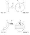
- FIGS. 7A and 7Bare schematic views of one embodiment of a facet joint prosthesis comprising a circular disc
- FIG. 8is a schematic view of the prosthesis from FIG. 7A implanted in a facet joint
- FIGS. 9A and 9Bare schematic views of one embodiment of a facet joint prosthesis comprising an octagonal disc
- FIGS. 10A and 10Bare schematic views of one embodiment of a facet joint prosthesis comprising a biconcave disc
- FIGS. 11A and 11Bare schematic views of one embodiment of a facet joint prosthesis comprising a single-face variable thickness disc;
- FIGS. 12A and 12Bare schematic views of one embodiment of a facet joint prosthesis comprising a curved disc
- FIG. 13is a schematic view of the prosthesis from FIG. 12A implanted in a facet joint;
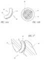
- FIGS. 14A and 14Bare schematic views of one embodiment of a facet joint prosthesis comprising a disc with a roughened surface on one face;
- FIGS. 15A and 15Bare schematic views of one embodiment of a facet joint prosthesis comprising a disc with a porous surface on one face;
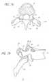
- FIGS. 16A and 16Bare schematic views of one embodiment of a facet joint prosthesis comprising a bent disc with a roughened surface on the greater face;
- FIG. 17is a schematic view of the prosthesis from FIG. 16A implanted in a facet joint;
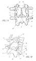
- FIGS. 18A and 18Bare schematic views of one embodiment of a facet joint prosthesis comprising two discs, each with a roughened surface on one face;
- FIG. 19is a schematic view of the prosthesis from FIG. 18A implanted in a facet joint;
- FIG. 20is a schematic view of a retaining member comprising a braided cable
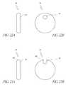
- FIGS. 21A and 21Bare schematic views of one embodiment of a facet joint prosthesis with a retaining interface comprising a centrally located hole;
- FIGS. 22A and 22Bare schematic views of one embodiment of a facet joint prosthesis with a retaining interface comprising an eccentrically located hole;
- FIGS. 23A and 23Bare schematic views of one embodiment of a facet joint prosthesis with a retaining interface comprising an edge contiguous hole;
- FIGS. 24A and 24Bare schematic views of one embodiment of a facet joint prosthesis comprising two discs, each with an eccentrically located hole;
- FIGS. 25A and 25Bare schematic views of one embodiment of a facet joint prosthesis comprising a curved disc with a retaining interface
- FIG. 26depicts one embodiment of the invention where the cable is engaged to the articular processes using knots in the cable;
- FIGS. 27A and 27Bdepict another embodiment of the retaining member comprising a braided cable with threaded ends adapted to accept threaded nuts;
- FIG. 28depicts one embodiment of the invention where a cable is engaged to the articular processes using nuts threaded onto the cable;
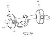
- FIG. 29depicts a preferred embodiment of the invention comprising a curved prosthesis, cable and two set-screw retaining rings;
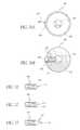
- FIGS. 30A and 30Bare elevational and cross-sectional views of one embodiment of the set-screw retaining rings, respectively;
- FIGS. 31 through 33are elevational views of various embodiments of the screw in the set-screw retaining rings
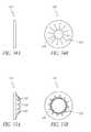
- FIGS. 34A to 35Bare one embodiment of the invention comprising friction fit retaining rings.
- FIGS. 34A and 34Bdepict the retaining rings in their reduced state and
- FIGS. 35A and 35Bdepict the retaining rings in their expanded state;
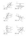
- FIGS. 36A to 36Cillustrate embodiments of the invention comprising a prosthesis with a close-ended threaded retaining interface and a threaded retaining member;
- FIG. 37Ais a cross sectional view of the prosthesis in FIG. 36A implanted in a facet joint
- FIG. 37Bis a cross sectional view of the prosthesis in FIG. 36B implanted in a facet joint;
- FIG. 38is a cross sectional view of a two-part prosthesis comprising flat discs implanted into a facet joint;
- FIG. 39is a cross sectional view of a two-part prosthesis comprising curved discs implanted into a facet joint;
- FIGS. 40A and 40Bare schematic views of one embodiment of a facet joint prosthesis with an integral retaining member comprising a centrally located barbed spike;
- FIGS. 41A and 41Bare schematic views of one embodiment of a facet joint prosthesis with an integral retaining member comprising an eccentrally located barbed spike;
- FIG. 42depicts the prosthesis of FIG. 38A implanted into a facet joint
- FIG. 43illustrates a two-part prosthesis implanted into a facet joint
- FIG. 44shows one embodiment of the invention comprising a prosthesis with multiple anchoring projections
- FIG. 45shows the prosthesis of FIG. 44 implanted into a facet joint
- FIGS. 46A and 46Bdepict one embodiment of the invention comprising a prosthesis with a rigid soft tissue side anchor
- FIGS. 47A and 47Bdepict one embodiment of the invention comprising a prosthesis with an embedded flexible soft tissue side anchor
- FIG. 48depicts one embodiment of the invention depicting a posterior surgical approach for implanting a prosthesis in the cervical vertebrae
- FIG. 49depicts one embodiment of the invention depicting the cross-sectional surgical approach for implanting a prosthesis in the cervical vertebrae
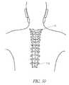
- FIG. 50depicts one embodiment of the invention depicting a posterior surgical approach for implanting a prosthesis in the thoracic vertebrae.
- FIGS. 51A to 51Edepicts one embodiment of the invention depicting a posterior surgical approach for implanting a prosthesis in the lumbar vertebrae;
- FIGS. 51A to 51Care posterior views of the surgical procedure and
- FIGS. 51D and 51Eare cross sectional views of the surgical procedure.
- FIGS. 52A to 52Eillustrate one embodiment of the tool with a single punch arm and plate.
- FIG. 52Fis a wire frame model of the embodiment depicted in FIGS. 52A to 52E .
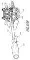
- FIGS. 53A to 53Fare one embodiment of the tool with punch drill arms.
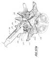
- FIG. 54depicts the distal end of the tool of FIGS. 53A to 53F without a frame member.
- FIG. 55is a component view of the tool shown in FIGS. 53A to 53F .
- FIGS. 56A to 56Care sequential schematic representations of the use of the tool shown in FIGS. 53A to 53F .
- FIGS. 57A to 57Eshow an embodiment of the method of use of the tool in FIGS. 52A to 52F wherein it is used to create a hole in the articular process of the vertebra.
- FIGS. 58A to 58Gshow an embodiment of the method of use of the tool in FIGS. 53A to 53E wherein it is used to create a hole in the articular process of the vertebra.
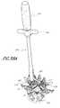
- FIGS. 59A to 59Dshow one embodiment of the tool with dual punch arms and a spacer.
- FIG. 60shows an embodiment of the method of use of the tool in FIGS. 59A to 59D 53 E wherein it is used to create a hole in the articular process of the vertebra.
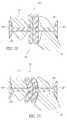
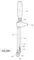
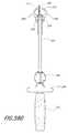
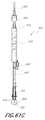
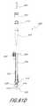
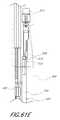
- FIGS. 61A to 61Dillustrate various views of the curved lumen forming tool having a drill bit, according to an embodiment of the present invention.
- FIG. 61Eillustrates the internal components of the handle in FIGS. 61A to 61D .
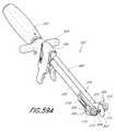
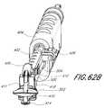
- FIGS. 62A and 62Billustrate a side elevational view and front close-up perspective view of the tool in FIGS. 61A to 61D with the lumen-forming arm in the extended configuration.
- FIGS. 63A to 63Dillustrate an embodiment of the method of use of the tool in FIGS. 61A to 61D wherein the tool is positioned among the articular processes of the vertebrae.
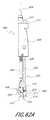
- FIGS. 64A and 64Billustrate sequential schematic representations of the use of the tool in FIGS. 61A to 61D to secure the tool to the articular processes of the vertebrae.
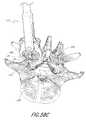
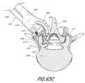
- FIGS. 65A to 65Dillustrate sequential schematic representations of the use of the tool in FIGS. 61A to 61D to create a hole in the articular processes of the vertebrae.
- FIG. 66illustrates a hole created in the articular processes of the vertebrae by the tool in FIGS. 61A to 61D .
- FIG. 67shows one embodiment of the tool with dual-lumen forming arms.
- the vertebral column 2comprises a series of alternating vertebrae 4 and fibrous discs 6 that provide axial support and movement to the upper portions of the body.
- the vertebral column 2typically comprises thirty-three vertebrae 4 , with seven cervical (C1-C7), twelve thoracic (T1-T12), five lumbar (L1-15), five fused sacral (S1-S5) and four fused coccygeal vertebrae.
- FIGS. 2A and 2Bdepict a typical thoracic vertebra.
- Each vertebraincludes an anterior body 8 with a posterior arch 10 .
- the posterior arch 10comprises two pedicles 12 and two laminae 14 that join posteriorly to form a spinous process 16 .
- a transverse 18 , superior 20 and inferior articular process 22Projecting from each side of the posterior arch 10 is a transverse 18 , superior 20 and inferior articular process 22 .
- the facets 24 , 26 of the superior 20 and inferior articular processes 22form facet joints 28 with the articular processes of the adjacent vertebrae. See FIGS. 3A and 3B .
- the facet jointsare true synovial joints with cartilaginous surfaces and a joint capsule.
- FIGS. 4A to 6Bdepict the orientations of the facet joints at different levels of the vertebral column.
- the facetsare oriented at a 45-degree angle to the transverse plane 30 and parallel to the frontal plane 32 , respectively. This orientation allows the facet joints of the cervical vertebrae to flex, extend, lateral flex and rotate.
- the facet joints of the cervical spinecan guide, but do not limit, the movement of the cervical vertebrae.
- FIGS. 6A and 6Bdepict the thoracic vertebrae, where the facets are oriented at a 60-degree angle to the transverse plane 30 and a 20-degree angle to the frontal plane 32 , respectively.
- This orientationis capable of providing lateral flexion and rotation, but only limited flexion and extension.
- FIGS. 6A and 6Billustrate the lumbar region, where the facet joints are oriented at 90-degree angles to the transverse plane 30 and a 45-degree angle to the frontal plane 32 , respectively.
- the lumbar vertebraeare capable of flexion, extension and lateral flexion, but little, if any, rotation because of the 90-degree orientation of the facet joints in the transverse plane.
- the actual range of motion along the vertebral columncan vary considerably with each individual vertebra.
- the facet jointsIn addition to guiding movement of the vertebrae, the facet joints also contribute to the load-bearing ability of the vertebral column.
- the facet jointsmay also play a role in resisting shear stresses between the vertebrae. Over time, these forces acting on the facet joints can cause degeneration and arthritis.
- a device for restoring the spacing between two facets of a facet jointcomprises a prosthesis 34 with a least two faces, a first face 36 adapted to contact the articular surface of one facet of the facet joint and a second face 38 adapted to contact the articular surface of the other facet.
- the prosthesis 34has a generally circular profile and is sized to fit generally within the joint capsule of the facet joint 28 .
- FIG. 8illustrates the prosthesis 34 of FIGS. 7A and 7B positioned in a facet joint.
- the prosthesiscan have any of a variety of profiles, including but not limited to square, rectangle, oval, star, polygon or combination thereof.
- An octagonal prosthesisis shown in FIGS. 9A and 9B .
- a prosthesis having the desired shapeis selected from an array of prostheses after radiographic visualization of the articular processes and/or by radio-contract injection into the facet joint to visualize the joint capsule.
- the prosthesishas a diameter of about 4 mm to about 30 mm.
- the prosthesishas a diameter of about 5 mm to about 25 mm.
- the prosthesishas a diameter of about 10 mm to about 20 mm.
- the prosthesishas a cross-sectional area of about 10 mm 2 to about 700 mm 2 . In another embodiment, the prosthesis has a cross-sectional area of about 25 mm 2 to about 500 mm 2 . In still another embodiment, the prosthesis has a cross-sectional area of about 20 mm 2 to about 400 mm 2 , and preferably about 25 mm 2 to about 100 mm 2 .
- the prosthesishas a thickness generally equal to about the anatomic spacing between two facets of a facet joint.
- the prosthesisgenerally has a thickness within the range of about 0.5 mm to about 3.0 mm. In certain embodiments, the prosthesis has a thickness of about 1 mm to about 2 mm. In one preferred embodiment, the prosthesis has a thickness of about 0.5 mm to about 1.5 mm. In one embodiment, the thickness of the prosthesis is nonuniform within the same prosthesis. For example, in FIGS. 10A and 10B , the thickness of the prosthesis 42 is increased around the entire outer edge 44 , along at least one and, as illustrated, both faces 46 , 48 . In FIGS.
- edge 44 on one face 46 of the prosthesis 42has a thickness that is greater than the thickness of a central region, and, optionally, also thicker than the typical anatomic spacing between two facets of a facet joint.
- An increased edge thicknessmay resist lateral displacement of the prosthesis out of the facet joint.
- the prosthesisis configured to provide an improved fit with the articular process and/or joint capsule.
- the prosthesis 49has a bend, angle or curve 50 to generally match the natural shape of an articular facet.
- FIG. 13depicts the prosthesis of FIGS. 12A and 12B positioned in a facet joint.
- the prosthesismay be rigid with a preformed bend.
- the prosthesismay be sufficiently malleable that it will conform post implantation to the unique configuration of the adjacent facet face. Certain embodiments of the invention, such as those depicted in FIG. 8 and FIG.
- the prosthesisis configured to be implanted between the articular processes and/or within the joint capsule of the facet joint, without securing of the prosthesis to any bony structures.
- Such embodimentscan thus be used without invasion or disruption of the vertebral bone and/or structure, thereby maintaining the integrity of the vertebral bone and/or structure.
- At least a portion of one surface of the prosthesisis highly polished.
- a highly polished portion of the prosthesismay reduce the surface friction and/or wear in that portion of the prosthesis as it contacts bone, cartilage or another surface of the prosthesis.
- a highly polished surface on the prosthesismay also decrease the risk of the prosthesis wedging between the articular surfaces of the facet joint, which can cause pain and locking of the facet joint.
- At least a portion of one surface of the prosthesis 50has a roughened surface 52 .
- a roughened surfacemay be advantageous when in contact with a bone or tissue surface because it may prevent slippage of the prosthesis 50 against the bone and aid in maintaining the prosthesis 50 in the joint.
- at least a portion of one surface of the prosthesis 50has a porous surface 54 .
- a porous surface 54can be created in any a variety of ways known in the art, such as by applying sintered beads or spraying plasma onto the prosthesis surface.
- a porous surface 54can allow bone to grow into or attach to the surface of the prosthesis 50 , thus securing the prosthesis 50 to the bone.
- an adhesive or sealantsuch as a cyanoacrylate, polymethylmethacrylate, or other adhesive known in the art, is used to bond one face of the prosthesis to an articular surface.
- one surface of the prosthesisis roughened or porous and a second surface that is highly polished.
- the first surfacecontacts or engages one facet of the facet joint and aids in maintaining the prosthesis between the articular surfaces.
- the second surface of the prosthesisis highly polished and contacts the other facet of the facet joint to provide movement at that facet joint.
- FIGS. 16A and 16Brepresent one embodiment of the prosthesis comprising a curved or bent disc 56 with a roughened surface 52 on the greater face 58 of the disc and a highly polished surface 60 on the lesser face 62 .
- FIG. 17depicts the prosthesis of FIGS. 16A and 16B positioned in a facet joint.
- the prosthesisgenerally maintains a fixed position relative to the facet contacting the roughened surface while the movement of the facet joint is preserved between the other facet and the highly polished lesser face of the prosthesis.
- FIGS. 18A and 18Bshow one embodiment of the invention, where the prosthesis 64 comprises two separate discs 66 , each disc comprising a first face 68 that articulates with the complementary first face 68 of the other disc, and a second face 70 adapted to secure the disc to the adjacent bone or cartilage of one facet of the facet joint 28 .
- the thickness of one discwill generally be about half of the anatomic spacing between two facets of the facet joint.
- the prosthesiscomprises three or more discs.
- the total thickness of all the discsis generally about 25% to about 300% of the anatomic spacing between the two facets.
- the total thickness of the discsis generally about 50% to about 150% of the anatomic spacing.
- the total thickness of the discsis about 75% to about 125% of the anatomic spacing.
- Each disc of the two-part prosthesiscan otherwise also have features similar to those of a single-disc prosthesis, including but not limited to curved or bent configurations, highly polished or roughened surfaces, and other feature mentioned below.
- the two discsneed not have the same size, thickness, configuration or features.
- FIG. 19depicts one embodiment of a two-part prosthesis 64 positioned within a facet joint 28 .
- the prosthesiscan be manufactured from any of a variety of materials known in the art, including but not limited to a polymer such as polyetheretherketone (PEEK), polyetherketoneketone (PEKK), polyethylene, fluoropolymer, hydrogel, or elastomer; a ceramic such as zirconia, alumina, or silicon nitride; a metal such as titanium, titanium alloy, cobalt chromium or stainless steel; or any combination of the above materials.
- a polymersuch as polyetheretherketone (PEEK), polyetherketoneketone (PEKK), polyethylene, fluoropolymer, hydrogel, or elastomer
- a ceramicsuch as zirconia, alumina, or silicon nitride
- a metalsuch as titanium, titanium alloy, cobalt chromium or stainless steel; or any combination of the above materials.
- the prosthesisis maintained between the two facets of the facet joint by taking advantage of the joint capsule and/or other body tissue surrounding the facet joint to limit the migration of the prosthesis out of the facet joint.
- the shape of the prosthesis itselfis capable of resisting displacement of the prosthesis from its position generally between the facet joint surfaces.
- a concave or biconcave configurationresists displacement of the prosthesis by providing an increased thickness at the periphery of the prosthesis that requires a larger force and/or greater distraction of facet joint surfaces in order to cause displacement.
- surface treatments or texturingare used to maintain the prosthesis against a facet of the facet joint, as described previously.
- a combination of disc configuration, surface texturing and existing body tissue or structuresare used to maintain the position of the prosthesis.
- Bone growth facilitatorsmay be used to accelerate osteoincorporation of textured or microporous anchoring surfaces.
- the prosthesismay be configured with a retaining interface to engage a retaining member that facilitates retention of the prosthesis within the joint capsule of the facet joint.
- a retaining membermay be advantageous for preventing migration of the prosthesis over time use or with the extreme ranges of vertebral movement that may distract the articular surfaces sufficiently to allow the prosthesis to slip out.
- the retaining membercomprises a wire or cable 72 with a portion 74 that engages the prosthesis 76 at a retaining interface 78 , and at least one other portion 80 that engages or anchors to the bone or soft tissue surrounding the facet joint.
- the wire or cablemay be solid, braided or multi-filamented.
- the retaining member in this embodimentwill be described primarily as a cable or wire, but it is to be understood that any of a variety of elongate structures capable of extending through a central aperture will also work, including pins, screws, and single strand or multistrand polymeric strings or weaves, polymeric meshes and fabric and other structures that will be apparent to those of skill in the art in view of the disclosure herein.
- the cross-sectional shape of the retaining membercan be any of a variety of shapes, including but not limited to circles, ovals, squares, rectangles, other polygons or any other shape.
- the wire or cablegenerally has a diameter of about 0.5 mm to about 2 mm and a length of about 5 mm to about 60 mm. In another embodiment, wire or cable has a diameter of about 0.25 mm to about 1 mm, and preferably about 0.75 mm to about 1.25 mm. The diameter of the wire or cable may vary along the length of the wire or cable. In one embodiment, the wire or cable has a length of about 10 mm to about 40 mm. In another embodiment, the wire or cable has a length of about 20 mm to about 30 mm.
- the retaining interface 78 of the prosthesis 76is a conduit between the two faces 82 , 84 of the prosthesis 76 , forming an aperture 78 .
- the aperture 78has a diameter larger than the diameter of the wire or cable 72 , to provide the prosthesis 76 with a range of motion as the facet joint moves.
- the aperture 78 inside diametermay be at least about 110%, often at least about 150% and in certain embodiments at least about 200% or 300% or greater of the outside diameter or corresponding dimension of the retaining member in the vicinity of the engagement portion 78 .
- the cross-sectional shape of the aperture 78can match or not match the cross sectional shape of the wire or cable used.
- the retaining interface 78extends only partially through the prosthesis 72 .
- the retaining interface 78may be located generally in the center of the prosthesis, or it may be located eccentrically, as depicted in FIGS. 22A and 22B .
- the retaining interface 78is located at the edge 86 of the prosthesis 76 such that the interior surface of the hole 78 is contiguous with the outer edge of the prosthesis. This configuration of the retaining interface 78 does not require the cable 72 to be threaded through the retaining interface 78 and may facilitate engagement of the retaining member with the prosthesis.
- FIGS. 24A and 24Bdepict an embodiment of the invention comprising a two-part prosthesis 88 . Either a single cable or two separate cables may be used retain both discs within the facet joint.
- FIGS. 25A and 25Bdepict another embodiment of the invention comprising a curved prosthesis 90 with a retaining interface 78 adapted to accept a cable.
- the wire or cable 72is secured to the articular processes 20 , 22 by tying one or more knots 92 in the cable 72 that can resist pulling of the wire or cable through the articular process.
- one or both ends of the wire or cableare provided with an anchor to resist migration of the implants.
- one or both ends of the wire or cable 72may be threaded such that a nut 94 can be tightened on the wire or cable 72 to secure the wire or cable to the articular processes 20 , 22 .
- FIG. 28depicts the attachment of a nut onto a threaded end of a cable.
- the threaded portion 96 of the wire or cablecan be secured to the cable by pressing, crimping or twisting the threaded 96 portion onto the cable 72 .
- the threaded portion 96is made from titanium, titanium alloy, cobalt chromium, stainless steel, or any combination thereof.
- the wire or cablehas two threaded ends 96 for engaging the bony or cartilaginous tissue, one portion for each facet of the facet joint.
- the wire or cableis secured to the articular process with retaining rings 98 .
- the retaining rings 98comprise a ring 100 with a central lumen 102 and a locking element to facilitate locking the ring 100 to a retaining member.
- the central lumen 102is adapted to accept insertion of a wire or cable through it.
- the illustrated locking elementis in the form of a side lumen 104 which is threaded and configured to accept a rotatable screw 106 with a proximal end 108 , a threaded body 110 and a distal end 112 .
- the threaded body 110is complementary to the threads of the side lumen 104 so that when the screw 106 is rotated at its distal end 112 , the proximal end 108 of the screw 106 moves further into the central lumen 102 and is capable of applying increasing force to a wire or cable inserted through the central lumen 102 .
- the force on the wire or cableis capable of creating a friction fit or a mechanical interfit to resist movement between the wire or cable and the retaining ring 98 , thereby securing the wire or cable to the articular process 20 or 22 .
- the distal end 112 of the screw 106can be configured to engage the wire or cable in any of a variety designs, including but no limited to a blunt tip 114 , curved tip 116 and piercing tip 118 .
- the wire or cableis securable to the articular process with a retaining ring 120 have radially inward biased projections 122 defining a central lumen 124 .
- the central lumenhas a cross-sectional shape smaller than that of the wire or cable but is capable of enlargement when the inward projections 122 are bent away, as shown in FIGS. 35A and 35B .
- the inward projections 122apply increasing force to the wire or cable within the central lumen 124 as the projections 122 are bent, thereby creating a friction fit.
- one end of the wire or cable retaining memberis preformed with a retainer for engaging the articular process.
- the retainermay be a preformed ring, bulb, flared end, T-bar end, or any of a variety of shapes having a greater cross sectional area than the other portions of the wire or cable retaining member.
- This configuration of the wire or cable retaining memberis adapted to engage an articular process by passing the free end of a wire or cable retaining member through an articular process such that the end with the preformed retainer can engage the articular process.
- the wire or cable retaining memberis secured to the articular processes with sufficient laxity or length between the secured ends or between the prosthesis and one secured end so that the two articular processes are not fixed in position relative to each other and remain capable of performing movements such as flexion, extension, lateral flexion and/or rotation.
- the retaining membercomprises a cable of braided polymer, including but not limited to a braided polymer such as PEEK or PEKK, or a braided metal, such as braided cobalt chromium or titanium.
- the cablecan be selected with different degrees of flexibility to provide different degrees of movement at that facet joint.
- the cablehas a first segment capable of engaging the prosthesis at its retaining interface to limit the movement
- the retaining membercomprises a screw or bolt 126 with a proximal end 128 , body 130 and distal end 132 .
- the distal end 132 of the screw or boltis capable of forming a mechanical interfit with a complementary retaining interface 134 on the prosthesis or spacer 136 .
- the distal end 132typically comprises threads, but one skilled in the art will understand that other configurations may be used to form a mechanical interfit.
- the complementary retaining interface 134 on the prosthesis 136could be a threaded through hole or preferably, a close-ended hole.
- the proximal end 128 of the screw or bolt 126has a hex or other type of interface known in the art, capable of engaging a rotating tool to manipulate the screw or bolt 126 .
- the body of the screw or bolt 126has a length sufficient to at least span the length of the hole or conduit created through the articular process for securing the prosthesis.
- the retaining memberfurther comprises a pivotable washer 127 with a pivot surface 129 that articulates with the proximal end 128 of the screw 126 .
- the pivotable washer 127is capable of a range of positions relative to the screw 126 and provides the screw 126 with a better surface area contact with the bone.
- FIG. 37is a cross-sectional view of a facet joint 28 with a spacer 136 bolted to one articular process 20 of a facet joint 28 .
- the spacer 136 positionis fixed relative to one facet 24 of the joint 28 , but provides for spacing and movement of the other facet 26 with respect to the spacer 136 .
- each discmay have its own screw or bolt retaining member.
- FIG. 38depicts a flat two-part prosthesis 138 and
- FIG. 39depicts a curved two-part prosthesis 140 .
- the retaining memberis integral with or attached to the prosthesis and comprises a projection 142 from the prosthesis 144 that is adapted to engage the adjacent articular process or surrounding tissue.
- the projectioncomprises at least one spike 142 or hook projecting from one face of the prosthesis 144 .
- the spike 142 or hookcan be ribbed, barbed or threaded to resist separation after insertion into bone or tissue.
- FIG. 42depicts the prosthesis 144 of FIG. 40A engaged to a facet 24 of the facet joint 28 .
- each disc 148may have its own projection-retaining member 142 .
- FIG. 44more than one projection 150 is provided on the prosthesis 152 .
- FIG. 45illustrates the prosthesis of FIG. 44 placed in a facet joint 28 .
- the projections 150may be angled with respect to the prosthesis 152 to resist dislodgement by the movement at the joint.
- FIGS. 46A to 47Billustrate embodiments of the invention where the retaining member comprises a projection 154 extending laterally such as from the side of the prosthesis 156 , and adapted to engage the soft tissue surrounding the facet joint, rather than a bony or cartilaginous articular process.
- the prosthesis of FIG. 46could be inserted into a facet joint through an incision made in the joint capsule, but the integrity of the joint capsule opposite the incision site is maintained and used as an anchoring site for the prosthesis.
- the orientation of the projectioncan be fixed as in FIG. 44 , or flexible.
- a flexible tethersuch as a wire 158 with its proximal end 160 embedded in or otherwise attached to the prosthesis and one or more barbs which may be attached to its distal end 162 .
- a flexible projectionmay provide greater selection of soft tissue anchoring sites for the prosthesis.
- the joint capsuleis closed after placement of the prosthesis. Closure may be performed using adhesives, suturing, stapling or any of a variety of closure mechanisms known in the art.
- general anesthesiais achieved and the patient is positioned prone on a turning frame or three-point head rest attached to the table. Skeletal traction is performed using tongs. The patient is prepped and draped in the usual sterile fashion. Pre-operative radiographic films are reviewed and any vertebral anomalies or variations are noted.
- the spinous processesare palpated to identify the location of the cervical vertebrae and a skin incision is made over the desired vertebrae, as shown in FIG. 48 .
- a paraspinous skin incisionis made over the desired facet joint. The exposed skin edges and subcutaneous tissue are injected with epinephrine 1:500,000 solution to facilitate hemostasis.
- Dissection to the spinous processor facet jointis performed using an electrocautery knife.
- dissectionis performed along the nuchal ligament 164 to avoid cutting into vascular muscle tissue.
- Soft tissue retractorsare used to maintain tissue tension and aid the dissection process.
- the ligamentous attachments to the spinous process 16are detached and the facet joints are exposed.
- dissectionis performed through the muscle tissue to directly access the facet joint.
- the joint capsule of the facet jointis opened by incision or piercing.
- the facets of the facet jointare distracted as required to provide access to the joint space.
- the affected facet jointis sized and a joint prosthesis is selected.
- the articular process or processesare prepared for receiving the joint prosthesis, including but not limited to roughening the articular surface of the articular process and/or creating a hole for the prosthesis anchor or retaining member.
- the prosthesisis inserted into the facet joint space and the anchor or retaining member, if any is attached to the articular process. The steps are repeated until all the joint prostheses have been inserted.
- the surgical siteis closed in layers with a suction tube or drainage tube in place. The surgical site is cleaned and dressed.
- a midline skin incisionis made over the desired vertebrae.
- a paraspinous skin incisionis made over the desired facet joint.
- the exposed skin edges, subcutaneous tissue and erector spinae musclesare injected with epinephrine 1:500,000 solution to facilitate hemostasis.
- Dissectionis performed using an electrocautery knife or scalpel through the superficial and lumbodorsal fascia to the tips of the spinous processes.
- the erector spinae muscleis reflected laterally to the tips of the transverse processes, thereby exposing the posterior arch. After exposure of all the desired vertebrae is achieved, an intra-operative x-ray is obtained to confirm access to the desired vertebrae.
- the facets of the facet jointare distracted as required to provide access to the joint space.
- the joint capsule of the facet jointis opened by incision or piercing.
- the affected facet jointis sized and a joint prosthesis is selected.
- the articular process or processesare prepared for receiving the joint prosthesis, including but not limited to roughening the articular surface of the articular process and/or creating a hole for the prosthesis anchor or retaining member.
- the prosthesisis inserted into the facet joint space and the anchor or retaining member, if any is attached to the articular process. The steps are repeated until all the joint prostheses have been inserted.
- the surgical siteis closed in layers with a suction tube or drainage tube in place. The surgical site is cleaned and dressed.
- FIG. 51Aillustrates a midline skin incision is made over the desired vertebrae. The exposed skin edges and subcutaneous tissue are injected with epinephrine 1:500,000 solution to facilitate hemostasis.
- FIGS. 51B and 51Cdissection is continued to the lumbodorsal fascia and the surgical site is exposed by retracting the skin and subcutaneous tissue laterally.
- blunt finger dissectionis used between the multifidus and longissimus muscles to access the facet joints.
- Self-retaining Gelpi retractorsare inserted between the muscle groups. Electrocautery or elevators are used to separate the transverse fibers of the multifidus from their heavy fascial attachments. Exposure of the transverse processes and fascial planes is continued. Cautery may be used to provide hemostasis from the lumbar arteries and veins along the base of the transverse processes.
- the facets of the facet jointare distracted as required to provide access to the joint space.
- the joint capsule of the facet jointis opened by incision or piercing.
- the affected facet jointis sized and a joint prosthesis is selected.
- the articular process or processesare prepared for receiving the joint prosthesis, including but not limited to roughening the articular surface of the articular process and/or creating a hole for the prosthesis anchor or retaining member.
- the prosthesisis inserted into the facet joint and the anchor or retaining member, if any is attached to the articular process. The steps are repeated until all the joint prostheses have been inserted.
- the surgical siteis closed in layers over a suction tube and the skin flaps are sutured down to the fascia to eliminate any dead space in the tissue. The surgical site is cleaned and dressed.
- general or local anesthesiais achieved and the patient is positioned prone on a turning frame or three-point head rest attached to the table. Skeletal traction is performed using tongs. The patient is prepped and draped in the usual sterile fashion. Pre-operative radiographic films are reviewed and any vertebral anomalies or variations are noted. The spinous processes are palpated to identify the location of the cervical vertebrae and a small 1 cm skin incision is made over the desired insertion site. Hemostasis is achieved with infiltration of epinephrine 1:500,000 solution around the incision site. Under fluoroscopy, a trocar or needle is inserted through the incision site and joint capsule to the desired facet joint. The needle or trocar is replaced with an introducer.
- insertionis performed along the nuchal ligament to avoid cutting into vascular muscle tissue. In another embodiment, insertion is performed directly through the skin and muscle overlying the facet joint. The facets of the facet joint are distracted as required to provide access to the joint space.
- the affected facet jointis sized by injecting a radio-contrast agent into the facet joint and a joint prosthesis is selected.
- the articular process or processesare prepared for receiving the joint prosthesis, including but not limited to roughening the articular surface of the articular process and/or creating a hole using endoscopic instruments known in the art.
- the prosthesisis inserted into the facet joint space through the introducer and an anchor or retaining member, if any is attached to the articular process. The steps are repeated until all the joint prostheses have been inserted.
- the surgical siteis closed, cleaned and dressed.
- general or local anesthesiais achieved and the patient is positioned prone on a padded spinal operating frame.
- the patientis prepped and draped in the usual sterile fashion.
- Pre-operative radiographic filmsare reviewed and any vertebral anomalies or variations are noted.
- a small 1 cm skin incisionis made over the desired insertion site. Hemostasis is achieved by injecting epinephrine 1:500,000 solution around the incision site.
- a trocar or needleis inserted through the superficial and lumbodorsal fascia, the erector spinae muscle and joint capsule to access the facet joint.
- the trocar or needleis replaced with an introducer.
- the facets of the facet jointare distracted as required to provide access to the joint space.
- the affected facet jointis sized and a joint prosthesis is selected.
- the articular process or processesare prepared for receiving the joint prosthesis, including but not limited to roughening the articular surface of the articular process and/or creating a hole for the prosthesis anchor or retaining member, using endoscopic instruments known in the art.
- the prosthesisis inserted into the facet joint space and the anchor or retaining member, if any is attached to the articular process. The steps are repeated until all the joint prostheses have been inserted.
- the surgical siteis closed, cleaned and dressed.
- general or local anesthesiais achieved and the patient is positioned prone or kneeling on a padded spinal operating frame.
- intravenous pressureis reduced and blood loss during the procedure is decreased.
- the patientis prepped and draped in the usual sterile fashion.
- Pre-operative radiographic filmsare reviewed and any vertebral anomalies or variations are noted.
- a small 1 cm skin incisionis made over the desired insertion site. Hemostasis is achieved by injecting epinephrine 1:500,000 solution around the incision site.
- a trocar or needleis inserted through the lumbodorsal fascia. The trocar or needle is replaced with an introducer.
- radio-contrast agentis injected through the introducer to identify the junction between the lumbodorsal fascia and the multifidus and longissimus muscles.
- a blunt dissectoris inserted through the introducer to dissect between the multifidus and longissimus muscles and pierce the joint capsule to access the facet joints.
- the facets of the facet jointare distracted as required to provide access to the joint space.
- the affected facet jointis sized and a joint prosthesis is selected.
- the articular process or processesare prepared for receiving the joint prosthesis, including but not limited to roughening the articular surface of the articular process and/or creating a hole for the prosthesis anchor or retaining member.
- the prosthesisis inserted into the facet joint space and the anchor or retaining member, if any is attached to the articular process. The steps are repeated until all the joint prostheses have been inserted.
- the surgical siteis closed, cleaned and dressed.
- inventionscomprise tools and methods for creating holes or lumens through one or more articular processes of the vertebra to facilitate implantation of a prosthesis stabilizer or retainer.
- the holes or lumenshave a curved or non-linear configuration.
- the curved or non-linear configurationallows relatively greater penetration through the thicker portions of the articular process(es) and therefore the articular process(es) may be less likely to fracture during formation of the hole or lumen.
- various instrumentshave been proposed for drilling into and through bone, including for example, the curved drills described in U.S. Pat. Nos.
- the subject tooloffers the benefits of lumen formation through the articular processes within the limited surgical access available about the vertebra.
- the preferred devicesutilize one or more curved punch members or curved drills that rotate about an axis that is transverse to the movement plane of the curved punch or curved drill member. Unlike traditional orthopedic procedures that require unimpeded access to the surgical site due to the longitudinally-oriented surgical tools, the curved punch or curved drill members also permit access using a limited space or cavity around the articular processes.
- the terms “lumen-forming” and “lumen formation”refer to the creation of a hole, passageway or indentation generally such as by, for example, piercing, punching, boring, puncturing, or drilling.
- the tool 200comprises a shaft 202 with a proximal handle 204 and a movable distal lumen-forming member 206 and a distal opposing support member 208 .
- the lumen-forming member 206may comprise a punch or lumen-forming arm 210 with a punch or lumen-forming tip 212 .
- the arm 210 of the lumen-forming member 206may have a diameter in the range of about 1 mm to 5 mm, preferably about 2 mm to 4 mm, and most preferably about 3 mm.
- the lumen-forming tip 212can be of any appropriate configuration and with any number of points. In some embodiments, the lumen-forming tip 212 may be round, flat, beveled or stepped. In some embodiments of the lumen-forming tool with more than one tip, the tips may have a similar or different configurations.
- the support member 208permits stabilization of the articular processes as the lumen-forming member 206 passes or punctures through the bone.
- the support member 208may comprise a plate 214 that is flat or curved. In some embodiments, the plate 214 may have a concave or convex configuration.
- the plate 214may optionally comprise a recess 216 , depicted in FIG. 52E , to seat the articular process and/or to allow the lumen-forming tip 212 of the lumen-forming member 206 to penetrate through the bone and into the recess 216 .
- the support member 208may also comprise a textured surface to resist slippage, including but not limited to serrations, ridges or indentations, or comprise a slip-resistant material.
- the support member 208comprises a movable opposing plate 214 .
- the movable opposing plate 214may be connected by any of a variety of movable joints known in the art.
- the plate 214is connected to rest of the support member 208 with a pivot pin 215 .
- ball-and-socket jointsmay be used.
- the movable opposing plateallows increased conformance or seating of the tool against the articular process.
- the movable opposing plate 214pivots passively as the tool 200 is applied to the bone.
- the position or orientation of the movable opposing plate 214may be controlled at the proximal end of the tool 200 .
- Manipulation of the platemay be performed using push/pull rods, gears pull wires or combinations thereof, as is known to those of skill in the art.
- the platemay be biased in a particular orientation using springs or other bias structures.
- the lumen-forming member 206may be movably attached and secured to the distal frame 218 of the shaft 202 by a pivot pin 220 .
- the lumen-forming member 206may be moved between a closed configuration, depicted in FIG. 52C , to an open configuration, depicted in FIG. 52D , by a proximal actuator 222 that moves a control rod 224 within the shaft 202 of the tool 200 .
- a proximal actuator 222that moves a control rod 224 within the shaft 202 of the tool 200 .
- manipulation of the actuator 222causes a longitudinal movement of the control rod 224 , which in turn causes a translational/angular movement of a link member 226 joining the control rod 224 and lumen-forming member 206 using pivot pins 228 , 230 .
- the actuator 222may be connected to the control rod 224 directly, in which case the actuator 222 is also manipulated by pushing and pulling.
- the control rod 224may be straight or curved or a combination of these shapes.
- the control rod 224may be stiff, bendable, or partially stiff and partially bendable.
- the actuator 222is manipulated by rotation, through a threaded surface that rotatably interfaces with a threaded surface on the control rod 224 .
- a rotational coupling between the actuator 222 and the control rod 224may provide increased mechanical advantage to the lumen-forming member 206 for piercing through bone.
- a power sourcemay be provided for hydraulic, pneumatic or other power-assisted manipulation of the lumen-forming member 206 .
- the plate 214can be fixed, or movable with respect to the frame 218 .
- Various attachment meansinclude, but are not limited to, welding, brazing, gluing, cementing, pin, hinge, and ball and socket.
- the punch armis curved. Different curved shapes of the punch arm are possible.
- the punch arm 210is straight.
- the punch arm 210has at least one straight segment and at least one curved segment. The segments may lie within the movement plane of the punch arm 210 , or alternatively, one or more segments may lie outside the movement plane.
- the movement of both lumen-forming tips 212typically occurs in the same plane, but in other embodiments, the movement of each tip 212 may occur in different planes that intersect at the intermediate position.
- only one armmoves or the two arms may move asymmetrically.
- the lumen-forming armsmove sequentially or in an alternating manner.
- the punch arm 210is sized to be able to pass through the articular processes of the spine and the resulting hole is sized for a prosthesis retainer to be inserted.
- the sizeis appropriate for the retainer to slide or not slide in the hole, depending on the retainer design selected.
- the tool 200may be used by positioning the lumen-forming tip 212 against one articular process 22 and positioning the plate 214 against the corresponding articular process 20 .
- the tip 212is forced through both articular processes 20 , 22 while supported by the plate 214 support member 208 .
- FIG. 57Bdepicts one approach to the articular processes 20 , 22 that may be used with the tool 200 .
- the support member 208is applied to the articular process 20 of the inferior vertebra 238 , but in other embodiments, the support member 208 may be applied to the articular process 22 of the superior vertebra.
- the tool 232comprises dual lumen-forming members 206 that are movable in a pincher-like fashion.
- the tool 232comprises an shaft 202 with a proximal handle 204 and a distal frame member 218 with two lumen-forming members 206 connected to a frame 218 .
- Each lumen-forming member 206comprises an arm 210 with a piercing tip 212 at one end and is rotatably connected to the frame 218 by a pivot pin 220 .
- Each lumen-forming member 206is also joined to the control rod 224 by a link member 226 with pivot pins 228 , 230 , as depicted in FIGS. 54 and 55 .
- the control rod 224runs through the outer shaft 202 and connects to the actuator 222 preferably with threads.
- the outer shaft 202is connected at one end to the handle 204 .
- FIGS. 53A to 55have lumen-forming members that pivot in equal amounts, one of skill in the art will understand that the configuration may be modified to move differently. In one specific embodiment, only one lumen-forming member moves while the other member is fixed in position.
- One of skill in the artwill also recognize that other movements of the control rod, link members and lumen-forming members are not limited to pivoting or angular movements.
- Alternate embodiments of the dual-arm tool 232may include similar alternate structures as described for tool 200 above.
- one method of use for the tool 232comprises placing one lumen-forming tip 212 against an exposed articular process 22 of a superior vertebra 236 and placing the other lumen-forming tip 212 against the corresponding articular process 20 of the inferior vertebra 238 .
- the handle 204 of the tool 232is held while the actuator 222 is rotated. Rotation motion of the actuator 222 is transferred to the control rod 224 as a linear motion away from the actuator 222 via the threaded connection.
- FIGS. 56A to 56Cdepict the tool 232 after the formation of the passageway 234 , as the tool 232 is moved from a closed configuration, as shown in FIG. 56A , to an open configuration, as shown in FIG. 56C .
- the resulting passageway 234 through the articular processes 20 , 22may be straight or preferably curved, depending on the design of the lumen-forming member 206 and particularly the configuration of the lumen-forming arms 210 .
- the lumen-forming arm 210can be straight or preferably curved or non-linear.
- the two arms 210need not have the same configuration. They can be of any appropriate cross-section area or shape, including but not limited to triangular, square, rectangular, hexagonal, pentagonal, octagonal, heptagonal, round, elliptical, or any combination of shapes. These shapes are applicable to single-arm and two-arm tools 200 , 232 .
- the arms 210can have a similar configuration or different configurations.
- the two armspreferably move in the same movement plane and preferably move by rotating around rotational axes that are generally perpendicular to the movement plane.
- the armsmay have cutting edges along its length and exhibit some rotation along its longitudinal axis, similar to a drill.
- FIGS. 58D to 58Gillustrate various approaches and relative orientations that may be taken with the tool 232 with respect to the articular processes 20 , 22 and vertebrae 236 , 238 .
- the surgeonmay select a particular rotational and/or angular approach to the surgical site, depending upon the particular vertebral morphology of the patient, the extent and location of damage or injury, prior surgery, and other factors known in the art.
- the tool 300comprises dual lumen-forming members 206 that are movable in a pincher-like fashion in a manner similar to the tool 232 of FIGS. 53A to 53F described above.
- the tool 300comprises a shaft 202 with a proximal handle 204 and a distal frame member 218 with two lumen-forming members 206 connected to a frame 218 .
- Each lumen-forming member 206comprises an arm 210 with a piercing tip 212 at one end and is rotatably connected to the frame 218 by a pivot pin 220 .
- Each lumen-forming member 206is also joined to the control rod 224 by a link member 226 with pivot pins 228 , 230 .
- the control rod 224runs through the outer shaft 202 and connects to the actuator 222 preferably with threads.
- the outer shaft 202is connected at one end to the handle 204 .
- each lumen-forming member 206comprises a bend that puts the lumen-forming arm 210 and the lumen-forming tip (i.e., piercing tip) 212 in the same plane as the longitudinal axis of a spacing member 310 , to be described below.
- the lumen-forming tipis out of the plane as the shaft 202 .
- the tool 300further comprises a spacing member 310 that can be coupled to the shaft 202 through a detachable clipping member 306 .
- the spacing member 310comprises a spacing member shaft 304 that is connected to the clipping member 306 at the proximal end and a spacer 302 at the distal end.
- the spacer 302may comprise a disk-like member and two indentations 308 on each side of the disk-like member, and the indentations 308 are lined up or aligned with the lumen-forming member 206 to allow the lumen-forming tips 212 of the lumen-forming members 206 to penetrate through the bones and into the indentations 308 .
- the disk-like member of the spacer 302may have an opening or a hole instead of the indentations 308 , and the two lumen-forming tips 212 could make contact with each other through the opening or the hole after penetrating the bones.
- the spacer 302may have a curved shape disk-like member to facilitate positioning between the articular processes 20 and 22 .
- the disk-like member of the spacer 302may have different shape, size and thickness for used with different sized vertebra.
- the clipping member 306allows the spacing member 310 to be detached from and attached to the facet drill tool with ease.
- the spacing member shaft 304 or the connection between the spacing member shaft 304 and the spacer 302can be modified to have a bend, corner or curvature to position the spacer 302 for placing between the articular processes 20 , 22 and for lining up with the lumen-forming members.
- the spacing member 310may be configured to have the spacer 302 bend toward the lumen-forming members 206 , so the indentations 308 or the hole on the disk-like member of the spacer 302 are aligned with the lumen-forming tips.
- the spacing member 310may be used with either tool 200 or 232 , wherein the lumen-forming member 206 is in the same plane as the shaft 202 , as shown in FIGS. 52B and 53B .
- the spacing member 310may have a bend near the distal end of the spacer member spacing member shaft 304 that allows the spacer 302 to bend into the plane of the longitudinal axis of the shaft 202 , and the indentations 308 of the spacer 302 would be aligned with the lumen-forming tip 212 .
- the spacing member 310may be used with tool 200 .
- the spacing member 310may be configured to have a bend to allow the spacer 302 to bend into the plane of the lumen-forming arm 210 and the piercing tip 212 .
- the spacer 302may also be movably connected to the spacing member shaft 304 through a pivot joint, wherein the disk-like member of the spacer 302 may be tilted out of the plane of the spacing member shaft 304 to allow for adjusting the distance between the plate 214 and the spacer 302 when positioning the tool 200 onto the articular processes 20 , 22 .
- one method of use for the tool 300comprises placing one lumen-forming tip 212 against an exposed articular process 22 of a superior vertebra 236 , placing the other lumen-forming tip 212 against the corresponding articular process 20 of the inferior vertebra 238 , and positioning the spacer 302 between the articular processes 20 and 22 .
- the handle 204 of the tool 232is held while the actuator 222 is rotated. Rotation motion of the actuator 222 is transferred to the control rod 224 as a linear motion away from the actuator 222 via the threaded connection.
- This movement of the control rod 234is transferred to the lumen-forming members 206 via the link members 226 and pivot pins 228 , 230 as a pinching motion where the piercing tips 212 approach each other through the bone of the articular processes 20 , 22 . Movement of the lumen-forming tips 212 continues until they pierce through the articular processes 20 and 22 and make contact with the indentations 308 to form a curved or non-linear passageway 234 . In embodiments where the spacer has a hole instead of indentations, the lumen-forming tips 212 moves until they meet at an intermediate position to form a curved or non-linear passageway 234 through the articular processes 20 , 22 .
- FIGS. 59A to 60have lumen-forming members that pivot in equal amounts, one of skill in the art will understand that the configuration may be modified to move in differently. In one specific embodiment, only one lumen-forming member moves while the other member is fixed in position. One of skill in the art will also recognize that other movements of the control rod, link members and lumen-forming members are not limited to pivoting or angular movements. Alternate embodiments of the tool 300 may include similar alternate structures as described for tool 200 above and with reference to FIGS. 52A-58G .
- the movement of the lumen-forming members 206 and/or plate 214can be effected by manual force applied by a person, such as by his or her hands, or alternatively it can be supplied or supplemented with a motor, pneumatics, hydraulics, springs, and/or magnetics.
- a movable gripmay be used to manipulate and actuate the lumen-forming members of the tool.
- the gripmay be designed for rotational, pivoting linear relative movement, or combination thereof, depending on the mechanical advantage that may be needed to facilitate movement of the lumen-forming arm(s) and piercing through the articular processes.
- One embodiment of the toolmay comprise a squeeze handle for actuating the tool.
- the toolcomprises an actuator with a switch or trip mechanism. Movement of the lumen-forming tips can be effected with coaxial shafts, non-coaxial shafts, wires, rods, springs, hydraulics, gas cylinder, piston, gears, motor, electrical signal, magnetics, or other suitable means for communicating a signal or transferring movement or providing the closing force.
- Other embodiments of the toolinclude closing mechanisms that include compound leverage, ratcheting, and/or multistep closing.
- FIGS. 61A-62Bcan comprise a shaft 402 with a proximal handle 404 and a distal arm guide 406 .
- the arm guide 406contains a lumen-forming arm 410 that can be moved in the proximal-distal direction by manipulation of a proximal actuator 422 .
- the distal portionalso comprises an opposing target member 408 having a target plate 414 , as described in more detail below.
- the lumen-forming arm 410comprises a rotating drill bit 412 that can be connected to a drill motor by a drill coupler 424 disposed toward the proximal end of the tool 400 .
- a spacing member 500 with a spacer 502 at the distal endcan be coupled to the tool 400 .
- the spacing member 500can be at least partially supported on the tool 400 by a frame 418 and the proximal handle 404 .
- the spacing member 500can be secured to the tool 400 by a hook 510 , which can be released by a release button 514 , as discussed further below.
- the lumen-forming arm 410can be slideably contained within the shaft 402 and arm guide 406 .
- the lumen-forming arm 410can be moved between an advanced configuration, depicted in FIG. 62A , and a retracted configuration, depicted in FIG. 61B , by a proximal actuator 422 that moves the lumen-forming arm 410 axially along the shaft 402 of the tool 400 .
- manipulation of the actuator 422causes a longitudinal movement of the lumen-forming arm 410 .
- the actuator 422can be connected to the lumen-forming arm 410 directly, in which case the actuator 422 is also manipulated by pushing and pulling. In other embodiments, the actuator 422 can be connected to the lumen-forming arm 410 through mechanisms such as gears or hinges, wherein manipulation of the actuator 422 translates into longitudinal movement of the lumen-forming arm 410 .
- the lumen-forming arm 410can be straight or curved or a combination of these shapes. Different curved shapes of the arm are possible. In other embodiments, the lumen-forming arm 410 can have at least one straight segment and at least one curved segment.
- the lumen-forming arm 410is shaped to have a curved distal portion that has a desired arc so that the lumen-forming arm 410 follows a specified path when extended.
- the lumen-forming arm 410may be stiff, bendable, or partially stiff and partially bendable.
- the lumen-forming arm 410is sufficiently stiff such that the distal portion is biased in the desired arc shape.
- a power sourcemay be provided for hydraulic, pneumatic or other power-assisted manipulation of the lumen-forming arm 410 .
- the lumen-forming arm 410can comprise a tubular cover 411 with a rotating drill bit 412 disposed coaxially within the tubular cover's 411 central lumen, as illustrated in FIG. 62B .
- the rotating drill bit 412can be flexible and can be guided by the tubular cover 411 , which as described previously can have sufficient rigidity to guide the flexible rotating drill bit 412 into the shape of the desired facet lumen.
- the lumen-forming arm 410can comprise a rotating drill bit 412 without a tubular cover 411 .
- the rotating drill bit 412is preferably at least partially rigid and biased in the shape of the desired facet lumen so that the drill bit 412 can form the desired shaped lumen.
- the lumen-forming arm 410can be sized to be able to pass through the articular processes of the spine and the resulting hole is sized for a prosthesis retainer to be inserted.
- the lumen-forming arm 410can have a diameter in the range of about 1 mm to 5 mm, preferably about 2 mm to 4 mm, and most preferably about 3 mm.
- At an end of the rotating drill bit 412can be a drill bit tip 413 with a cutting surface for creating the lumen in the facets.
- the rotating drill bit tip 413can be of any appropriate configuration and with any number of points.
- the lumen-forming tip 413may be round, flat, beveled or stepped.
- the cutting surfacecan comprise any configuration that is known in the art for cutting through bone.
- the rotating drill bit 412can be connected to a drill coupler 424 to provide the axial rotation.
- the drill coupler 424can have a configuration that is complementary to a coupling of a hand or powered drill.
- the drill coupler 424can have a feature to provide an anti-rotational connection with the coupling on the drill, such as for example a flat surface, or a shaft having a square or hexagonal cross-section.
- the drill coupler 424can have a configuration to fit with a standard drill chuck.
- the drill coupler 424can have any other configuration that is complementary to a coupling on a drill.
- a target member 408 having a target plate 414can be connected to the frame 418 .
- the target plate 414is in the path of travel of the lumen forming arm 410 and thus the position of the target plate 414 against an articular process can provide indication to the user of where the lumen forming arm 410 will emerge from the articular processes during the drilling procedure.
- the target member 408can advantageously help the user avoid neural or other structures in and around the articular processes by visualizing and understanding the trajectory of the lumen forming arm 410 through the articular processes.
- the target member 408can provide some stabilization of the articular processes as the lumen forming arm 410 passes or cuts through the bone.
- the target plate 414can be flat or curved.
- the target plate 414can have a concave or convex configuration.
- the target plate 414can comprise an aperture 416 , depicted in FIG. 61D , to seat the articular process and/or to allow at least a portion of the lumen-forming arm 410 of the arm guide 406 to penetrate through the bone and through the aperture 416 .
- the target member 408can also comprise a textured surface to resist slippage, including but not limited to serrations, ridges or indentations, or comprise a slip-resistant material.
- the lumen-forming tool 400comprises a movable target member 408 .
- the movable target member 408may be connected by any of a variety of movable joints known in the art.
- the target member 408is connected to rest of the lumen-forming tool 400 with pivot pins 415 .
- Various other attachment meansinclude, but are not limited to, welding, brazing, gluing, cementing, pin, hinge, and ball and socket.
- the movable target member 408allows increased conformance or adjustment of the tool 400 against the articular processes.
- the movable target member 408pivots passively as the tool 400 is applied to the bone.
- the position or orientation of the movable target member 408can be controlled at the proximal end of the tool 400 .
- Manipulation of the platemay be performed using push/pull rods, gears pull wires or combinations thereof, as is known to those of skill in the art.
- the platemay be biased in a particular orientation using springs or other biasing structures.
- the tool 400can further comprise a spacing member 500 that can be coupled to the handle 404 , as illustrated in FIG. 61E .
- the spacing member 500can comprise a spacing member shaft 504 that is connected to a retention member 506 at the proximal end and has a spacer 502 at the distal end.
- the spacer 502can comprise a disk-like member and a spacer aperture 508 that is lined up with the lumen-forming arm 410 to allow the drill bit tip 413 of the lumen-forming arm 410 to penetrate through the bones and through the aperture 508 .
- the spacer 502can have a curved or cupped shape to facilitate positioning between the articular processes 20 and 22 . In some embodiments, the spacer 502 may have different shapes, sizes and thicknesses for use with different sized vertebra.
- the retention member 506allows the spacing member 500 to be detached from and attached to the facet drill tool 400 with ease.
- the retention member 506is disposed inside the proximal handle 404 and comprises a hook 510 that can engage with a notch 512 on the proximal end of the spacing member shaft 504 to secure the spacing member 500 to the tool 400 .
- the hook 510can have a tapered distal surface such that it automatically engages with the notch 512 when the spacing member shaft 504 is inserted proximally into the handle 404 .
- a release button 514can be disposed on the proximal handle 404 that disengages the hook 510 from the notch 512 when depressed, releasing the spacing member 500 .
- retention member 506is described herein, it is to be understood that any of a variety of retention mechanisms capable of easily attaching and detaching the spacing member 500 and tool 400 are also envisioned, including clamps, clips, ties, pins, adhesives and other structures that will be apparent to those of skill in the art in view of the disclosure herein.
- the spacing member shaft 504 or the connection between the spacing member shaft 504 and the spacer 502can be modified to have a bend, corner or curvature to position the spacer 502 for placing between the articular processes 20 , 22 and for lining up with the lumen-forming members.
- the spacing member 500can be disposed laterally adjacent the shaft 402 and may be configured such that the spacer 502 bends toward the arm guide 406 , so the spacer aperture 508 or indentations on the disk-like member of the spacer 502 are aligned with the path of the lumen-forming arm 410 .
- the spacer member 500can rotate about its longitudinal axis while coupled to the tool 400 to accommodate variations in the shapes and positions of the articular processes 20 , 22 , as illustrated in FIG. 62B .
- the spacer aperture 508is sufficiently large to allow the lumen-forming arm 410 to pass through the aperture 508 even when the spacer member 500 is at an angle to the lumen-forming arm 410 .
- a method of use for the tool 400can comprise inserting the spacing member 500 in the patient and positioning the spacer 502 in the facet joint space between the articular processes 20 , 22 .
- the tool 400can be guided over the spacing member shaft 504 until the hook 510 in the proximal handle 404 engages with the notch 512 on the spacing member 500 to lock the spacing member 500 to the tool 400 , as illustrated in FIGS. 63B and 63C .
- the tool 400may be used by positioning the drill bit tip 413 against one articular process 22 and positioning the target plate 414 against the corresponding articular process 20 .
- 63Dis a close-up of the distal portion of the tool 400 in position around articular processes 20 , 22 and illustrating the arm guide 406 , target plate 414 and the spacer 502 .
- the tool 400can be rotated axially relative to the spacing member 500 to adjust for variations in the native anatomy of the articular processes 20 , 22 .
- the surgeonmay select a particular rotational and/or angular approach to the surgical site, depending upon the particular vertebral morphology of the patient, the extent and location of damage or injury, prior surgery, and other factors known in the art.
- the drill bit tip 413cuts through both articular processes 20 , 22 toward the target plate 414 of the opposing target member 408 .
- the arm guide 406can be placed against an exposed articular process 22 of a superior vertebra 236 , placing the opposing target member 408 against the corresponding articular process 20 of the inferior vertebra 238 .
- FIG. 64Adepicts one approach to the articular processes 20 , 22 that may be used with the tool 400 .
- the target member 408can be applied to the articular process 20 of the inferior vertebra 238 , but in other embodiments, the target member 408 may be applied to the articular process 22 of the superior vertebra 236 .
- the spacer 502 of the spacing member 500is disposed in the facet joint space between the two articular processes.
- the tool 400can be adjusted so that a movable member of the tool 400 can secure to the outside of a facet joint or lamina.
- the anchor portion 426 of the arm guide 406is movable and has a pointed tip to secure to the facet 22 .
- the tool 400can have an arm guide adjustor 428 that can be actuated to extend and/or retract the anchor portion 426 of the arm guide 406 .
- a drill motorcan be attached to the drill coupler 424 to power the rotating drill bit 412 within the lumen-forming arm 410 . While the drill motor rotates the drill bit 412 , the proximal actuator 422 can be advanced in the distal direction to extend the lumen-forming arm 410 from the arm guide 406 and form a hole in the articular processes 20 , 22 , as illustrated in the cross-sectional views of FIGS. 65A-65D . In some embodiments, the shape of the distal portion of the lumen-forming arm 410 is curved, as described above, to create a curved hole in the articular processes 20 , 22 . As illustrated in the embodiment of FIG.
- the anchor portion 426 of the arm guide 406can extend and secure to the articular process 22 . Then the lumen-forming arm 410 with the rotating drill bit 412 and the drill bit tip 413 can be extended to cut the lumen in the articular processes 20 , 22 , as illustrated in FIG. 65B . With reference to FIG. 65C , the lumen-forming arm 410 can extend through the spacer aperture 508 . Then the lumen-forming arm 410 can continue to extend to the target plate 414 of the opposing target member 408 , as illustrated in FIG. 65D .
- the lumen-forming arm 410can be retracted by pulling the proximal actuator 422 in the proximal direction.
- the tool 600can comprise dual lumen-forming arms 410 , 410 ′ that can extend toward each other in a pincher-like fashion, similar to the dual-arm tool 232 described above.
- Each lumen-forming arm 410 , 410 ′can comprise rotating drills 412 , 412 ′ that are connected to two separate drill motors or a common drill motor.
- the two armsmay move asymmetrically.
- both lumen-forming armsmay move at the same time until they meet at an intermediate position. The movement of both lumen-forming arms typically occurs in the same plane, but in other embodiments, the movement of each arm may occur in different planes that intersect at the intermediate position.
- the disk-like member of the spacermay have indentations on each side of the disk-like member instead of a spacer aperture, and the indentations can be lined up or aligned with the lumen-forming arms to allow the drill tips to penetrate through the bones and into the indentations.
- the lumen-forming tipsmoves until they meet at an intermediate position to form a curved or non-linear passageway through the articular processes 20 , 22 .
- the size of the toolis appropriate for drilling the particular bone in the way that is desired. Smaller devices can be used for smaller vertebra and larger devices for larger vertebra. In addition, the device can be use on bones other than the vertebra and on bones for humans and non-humans. Other applications of the tool are for creating anchor points in bone for sutures and for bone immobilization such as with pins.
- the toolcan be made of any appropriate material for the particular part.
- Exemplary materialsinclude, but are not limited to, stainless steel, surgical steel, cutlery steel, tool steel, cobalt and its alloys, nickel and its alloys, chromium and its alloys, titanium and its alloys, zirconium and its alloys, aluminum and its alloys, magnesium and its alloys, polymers, elastomers, and ceramics.
- Ceramicsmay include, but are not limited to silicon carbide, silicon oxide(s), silicon nitride, aluminum oxide, alumina, zirconia, tungsten carbide, other carbides.
- inventionscomprise a method of forming a passageway in the articular processes of the vertebra using a facet lumen-forming tool described herein.
- the methodmay comprise placing the lumen-forming tips of the facet lumen-forming against a pair of articular processes of the vertebra, and actuating the lumen-forming member(s).
- Another embodimentmay comprise placing the lumen-forming tip and plate of the single-arm facet lumen-forming against the articular processes of the vertebra, and actuating the lumen-forming.
- a further embodiment of the inventionis a method of anchoring or restraining a prosthesis between the facet joints of the vertebra comprising forming a curved lumen through the articular processes with the facet lumen-forming tool described herein, positioning a facet joint implant into the facet joint associated with the articular processes and inserting an anchoring member through the curved lumen.
Landscapes
- Health & Medical Sciences (AREA)
- Surgery (AREA)
- Life Sciences & Earth Sciences (AREA)
- Orthopedic Medicine & Surgery (AREA)
- Medical Informatics (AREA)
- General Health & Medical Sciences (AREA)
- Veterinary Medicine (AREA)
- Engineering & Computer Science (AREA)
- Biomedical Technology (AREA)
- Heart & Thoracic Surgery (AREA)
- Public Health (AREA)
- Molecular Biology (AREA)
- Animal Behavior & Ethology (AREA)
- Nuclear Medicine, Radiotherapy & Molecular Imaging (AREA)
- Dentistry (AREA)
- Oral & Maxillofacial Surgery (AREA)
- Neurology (AREA)
- Pain & Pain Management (AREA)
- Rheumatology (AREA)
- Prostheses (AREA)
- Surgical Instruments (AREA)
Abstract
Description
Claims (19)
Priority Applications (9)
| Application Number | Priority Date | Filing Date | Title |
|---|---|---|---|
| US12/859,009US8992533B2 (en) | 2007-02-22 | 2010-08-18 | Vertebral facet joint drill and method of use |
| CA2804223ACA2804223C (en) | 2010-08-18 | 2011-08-11 | Vertebral facet joint drill and method of use |
| EP11818586.7AEP2605711B1 (en) | 2010-08-18 | 2011-08-11 | Vertebral facet joint drill |
| AU2011292297AAU2011292297C1 (en) | 2010-08-18 | 2011-08-11 | Vertebral facet joint drill and method of use |
| PCT/US2011/047432WO2012024162A1 (en) | 2010-08-18 | 2011-08-11 | Vertebral facet joint drill and method of use |
| JP2013524882AJP5859537B2 (en) | 2010-08-18 | 2011-08-11 | Intervertebral joint drill and method of use |
| AU2014277721AAU2014277721B2 (en) | 2010-08-18 | 2014-12-17 | Tool and method for forming a lumen |
| US14/629,830US9517077B2 (en) | 2007-02-22 | 2015-02-24 | Vertebral facet joint drill and method of use |
| JP2015242990AJP6212103B2 (en) | 2010-08-18 | 2015-12-14 | Intervertebral joint drill and method of use |
Applications Claiming Priority (3)
| Application Number | Priority Date | Filing Date | Title |
|---|---|---|---|
| US89115907P | 2007-02-22 | 2007-02-22 | |
| US12/035,366US8652137B2 (en) | 2007-02-22 | 2008-02-21 | Vertebral facet joint drill and method of use |
| US12/859,009US8992533B2 (en) | 2007-02-22 | 2010-08-18 | Vertebral facet joint drill and method of use |
Related Parent Applications (1)
| Application Number | Title | Priority Date | Filing Date |
|---|---|---|---|
| US12/035,366Continuation-In-PartUS8652137B2 (en) | 2007-02-22 | 2008-02-21 | Vertebral facet joint drill and method of use |
Related Child Applications (1)
| Application Number | Title | Priority Date | Filing Date |
|---|---|---|---|
| US14/629,830DivisionUS9517077B2 (en) | 2007-02-22 | 2015-02-24 | Vertebral facet joint drill and method of use |
Publications (2)
| Publication Number | Publication Date |
|---|---|
| US20110040301A1 US20110040301A1 (en) | 2011-02-17 |
| US8992533B2true US8992533B2 (en) | 2015-03-31 |
Family
ID=45607437
Family Applications (2)
| Application Number | Title | Priority Date | Filing Date |
|---|---|---|---|
| US12/859,009Active2029-03-30US8992533B2 (en) | 2007-02-22 | 2010-08-18 | Vertebral facet joint drill and method of use |
| US14/629,830ActiveUS9517077B2 (en) | 2007-02-22 | 2015-02-24 | Vertebral facet joint drill and method of use |
Family Applications After (1)
| Application Number | Title | Priority Date | Filing Date |
|---|---|---|---|
| US14/629,830ActiveUS9517077B2 (en) | 2007-02-22 | 2015-02-24 | Vertebral facet joint drill and method of use |
Country Status (6)
| Country | Link |
|---|---|
| US (2) | US8992533B2 (en) |
| EP (1) | EP2605711B1 (en) |
| JP (2) | JP5859537B2 (en) |
| AU (1) | AU2011292297C1 (en) |
| CA (1) | CA2804223C (en) |
| WO (1) | WO2012024162A1 (en) |
Cited By (29)
| Publication number | Priority date | Publication date | Assignee | Title |
|---|---|---|---|---|
| US20140094854A1 (en)* | 2012-09-28 | 2014-04-03 | Warsaw Orthopedic, Inc. | Spinal correction system and method |
| USD739935S1 (en) | 2011-10-26 | 2015-09-29 | Spinal Elements, Inc. | Interbody bone implant |
| US9271765B2 (en) | 2011-02-24 | 2016-03-01 | Spinal Elements, Inc. | Vertebral facet joint fusion implant and method for fusion |
| US9301786B2 (en) | 2011-02-24 | 2016-04-05 | Spinal Elements, Inc. | Methods and apparatus for stabilizing bone |
| US20160199200A1 (en)* | 2013-03-15 | 2016-07-14 | DePuy Synthes Products, Inc. | Methods and devices for removing a spinal disc |
| US9421044B2 (en) | 2013-03-14 | 2016-08-23 | Spinal Elements, Inc. | Apparatus for bone stabilization and distraction and methods of use |
| USD765853S1 (en) | 2013-03-14 | 2016-09-06 | Spinal Elements, Inc. | Flexible elongate member with a portion configured to receive a bone anchor |
| US9456855B2 (en) | 2013-09-27 | 2016-10-04 | Spinal Elements, Inc. | Method of placing an implant between bone portions |
| US20160317161A1 (en)* | 2013-03-15 | 2016-11-03 | Saddy Garcia | Sternal closure cerclage, plate implant and instrumentation |
| US9517077B2 (en) | 2007-02-22 | 2016-12-13 | Spinal Elements, Inc. | Vertebral facet joint drill and method of use |
| USD777921S1 (en) | 2011-02-24 | 2017-01-31 | Spinal Elements, Inc. | Interbody bone implant |
| US9675387B2 (en) | 2004-02-06 | 2017-06-13 | Spinal Elements, Inc. | Vertebral facet joint prosthesis and method of fixation |
| US9743937B2 (en) | 2007-02-22 | 2017-08-29 | Spinal Elements, Inc. | Vertebral facet joint drill and method of use |
| US9820784B2 (en) | 2013-03-14 | 2017-11-21 | Spinal Elements, Inc. | Apparatus for spinal fixation and methods of use |
| US9839450B2 (en) | 2013-09-27 | 2017-12-12 | Spinal Elements, Inc. | Device and method for reinforcement of a facet |
| US9931142B2 (en) | 2004-06-10 | 2018-04-03 | Spinal Elements, Inc. | Implant and method for facet immobilization |
| US10010359B2 (en) | 2013-03-15 | 2018-07-03 | Zimmer Biomet CMF and Thoracic, LLC | Sternal closure cerclage, plate implant and instrumentation |
| US10758361B2 (en) | 2015-01-27 | 2020-09-01 | Spinal Elements, Inc. | Facet joint implant |
| US11298143B2 (en)* | 2017-04-12 | 2022-04-12 | Smith & Nephew, Inc. | Surgical drill guide systems and methods of use thereof |
| US11304733B2 (en) | 2020-02-14 | 2022-04-19 | Spinal Elements, Inc. | Bone tie methods |
| US11457959B2 (en) | 2019-05-22 | 2022-10-04 | Spinal Elements, Inc. | Bone tie and bone tie inserter |
| US11464552B2 (en) | 2019-05-22 | 2022-10-11 | Spinal Elements, Inc. | Bone tie and bone tie inserter |
| US11478275B2 (en) | 2014-09-17 | 2022-10-25 | Spinal Elements, Inc. | Flexible fastening band connector |
| US12097129B2 (en) | 2013-11-13 | 2024-09-24 | Tornier Sas | Shoulder patient specific instrument |
| USD1044535S1 (en)* | 2022-07-26 | 2024-10-01 | Georg Rothbucher | Surveying instrument accessory |
| USD1060068S1 (en)* | 2022-05-05 | 2025-02-04 | Georg Rothbucher | Surveying instrument accessory |
| USD1060064S1 (en)* | 2022-07-26 | 2025-02-04 | Georg Rothbucher | Surveying instrument accessory |
| US12369952B2 (en) | 2021-12-10 | 2025-07-29 | Spinal Elements, Inc. | Bone tie and portal |
| US12440252B2 (en) | 2023-03-13 | 2025-10-14 | Zimmer Biomet CMF and Thoracic, LLC | Surgical plate fastener cartridge |
Families Citing this family (57)
| Publication number | Priority date | Publication date | Assignee | Title |
|---|---|---|---|---|
| US8361067B2 (en) | 2002-09-30 | 2013-01-29 | Relievant Medsystems, Inc. | Methods of therapeutically heating a vertebral body to treat back pain |
| US8696707B2 (en) | 2005-03-08 | 2014-04-15 | Zyga Technology, Inc. | Facet joint stabilization |
| US8617248B2 (en) | 2005-05-06 | 2013-12-31 | Titan Spine, Llc | Spinal implant having variable ratios of the integration surface area to the axial passage area |
| US8992622B2 (en) | 2005-05-06 | 2015-03-31 | Titan Spine, Llc | Interbody spinal implant having a roughened surface topography |
| US20120312779A1 (en) | 2005-05-06 | 2012-12-13 | Titian Spine, LLC | Methods for manufacturing implants having integration surfaces |
| US8814939B2 (en) | 2005-05-06 | 2014-08-26 | Titan Spine, Llc | Implants having three distinct surfaces |
| US8562684B2 (en) | 2005-05-06 | 2013-10-22 | Titan Spine, Llc | Endplate-preserving spinal implant with an integration plate having a roughened surface topography |
| US8480749B2 (en) | 2005-05-06 | 2013-07-09 | Titan Spine, Llc | Friction fit and vertebral endplate-preserving spinal implant |
| US8403991B2 (en) | 2005-05-06 | 2013-03-26 | Titan Spine Llc | Implant with critical ratio of load bearing surface area to central opening area |
| US8591590B2 (en) | 2005-05-06 | 2013-11-26 | Titan Spine, Llc | Spinal implant having a transverse aperture |
| US8551176B2 (en) | 2005-05-06 | 2013-10-08 | Titan Spine, Llc | Spinal implant having a passage for enhancing contact between bone graft material and cortical endplate bone |
| US8262737B2 (en) | 2005-05-06 | 2012-09-11 | Titan Spine, Llc | Composite interbody spinal implant having openings of predetermined size and shape |
| US9168147B2 (en) | 2005-05-06 | 2015-10-27 | Titan Spine, Llc | Self-deploying locking screw retention device |
| US8585765B2 (en) | 2005-05-06 | 2013-11-19 | Titan Spine, Llc | Endplate-preserving spinal implant having a raised expulsion-resistant edge |
| US8585767B2 (en) | 2005-05-06 | 2013-11-19 | Titan Spine, Llc | Endplate-preserving spinal implant with an integration plate having durable connectors |
| US11096796B2 (en) | 2005-05-06 | 2021-08-24 | Titan Spine, Llc | Interbody spinal implant having a roughened surface topography on one or more internal surfaces |
| US8585766B2 (en) | 2005-05-06 | 2013-11-19 | Titan Spine, Llc | Endplate-preserving spinal implant with an integration plate having durable connectors |
| US8758442B2 (en) | 2005-05-06 | 2014-06-24 | Titan Spine, Llc | Composite implants having integration surfaces composed of a regular repeating pattern |
| US8545568B2 (en) | 2005-05-06 | 2013-10-01 | Titan Spine, Llc | Method of using instruments and interbody spinal implants to enhance distraction |
| US8562685B2 (en) | 2005-05-06 | 2013-10-22 | Titan Spine, Llc | Spinal implant and integration plate for optimizing vertebral endplate contact load-bearing edges |
| US8758443B2 (en) | 2005-05-06 | 2014-06-24 | Titan Spine, Llc | Implants with integration surfaces having regular repeating surface patterns |
| US8435302B2 (en) | 2005-05-06 | 2013-05-07 | Titan Spine, Llc | Instruments and interbody spinal implants enhancing disc space distraction |
| US9125756B2 (en) | 2005-05-06 | 2015-09-08 | Titan Spine, Llc | Processes for producing regular repeating patterns on surfaces of interbody devices |
| US8343189B2 (en) | 2007-09-25 | 2013-01-01 | Zyga Technology, Inc. | Method and apparatus for facet joint stabilization |
| CA2737374C (en) | 2008-09-26 | 2017-03-28 | Relievant Medsystems, Inc. | Systems and methods for navigating an instrument through bone |
| US10028753B2 (en) | 2008-09-26 | 2018-07-24 | Relievant Medsystems, Inc. | Spine treatment kits |
| US8394125B2 (en) | 2009-07-24 | 2013-03-12 | Zyga Technology, Inc. | Systems and methods for facet joint treatment |
| US10098674B2 (en) | 2009-10-22 | 2018-10-16 | Nuvasive, Inc. | System and method for posterior cervical fusion |
| US9204906B2 (en) | 2009-10-22 | 2015-12-08 | Nuvasive, Inc. | Posterior cervical fusion system and techniques |
| US9233006B2 (en) | 2010-06-15 | 2016-01-12 | Zyga Technology, Inc. | Systems and methods for facet joint treatment |
| US8663293B2 (en) | 2010-06-15 | 2014-03-04 | Zyga Technology, Inc. | Systems and methods for facet joint treatment |
| JP5881696B2 (en)* | 2010-07-11 | 2016-03-09 | ミニンヴェイシヴ リミティッド | Annular bone tunneling device |
| AU2012298197B2 (en) | 2011-08-24 | 2016-12-01 | Mininvasive Ltd. | Arthroscopic surgical device |
| US9668783B2 (en)* | 2011-09-06 | 2017-06-06 | Atul Goel | Devices and method for treatment of spondylotic disease |
| US8992619B2 (en) | 2011-11-01 | 2015-03-31 | Titan Spine, Llc | Microstructured implant surfaces |
| AU2012362524B2 (en) | 2011-12-30 | 2018-12-13 | Relievant Medsystems, Inc. | Systems and methods for treating back pain |
| CA2880825C (en) | 2012-03-20 | 2021-03-16 | Titan Spine, Llc | Friction-fit spinal endplate and endplate-preserving method |
| US10588691B2 (en) | 2012-09-12 | 2020-03-17 | Relievant Medsystems, Inc. | Radiofrequency ablation of tissue within a vertebral body |
| EP2716261A1 (en) | 2012-10-02 | 2014-04-09 | Titan Spine, LLC | Implants with self-deploying anchors |
| US9498349B2 (en) | 2012-10-09 | 2016-11-22 | Titan Spine, Llc | Expandable spinal implant with expansion wedge and anchor |
| WO2014071161A1 (en) | 2012-11-05 | 2014-05-08 | Relievant Medsystems, Inc. | System and methods for creating curved paths through bone and modulating nerves within the bone |
| CA2887215A1 (en) | 2012-11-15 | 2014-05-22 | Zyga Technology, Inc. | Systems and methods for facet joint treatment |
| US9724151B2 (en) | 2013-08-08 | 2017-08-08 | Relievant Medsystems, Inc. | Modulating nerves within bone using bone fasteners |
| RU2539187C1 (en)* | 2013-09-09 | 2015-01-20 | Владимир Дмитриевич Шатохин | Rib perforator |
| US9615935B2 (en) | 2014-01-30 | 2017-04-11 | Titan Spine, Llc | Thermally activated shape memory spring assemblies for implant expansion |
| KR20180058729A (en) | 2015-09-24 | 2018-06-01 | 미닌베이시브 리미티드 | Arthroscopic device |
| WO2017115355A2 (en) | 2015-12-31 | 2017-07-06 | Mininvasive Ltd. | Arthroscopic surgical device |
| US10905473B2 (en)* | 2016-02-15 | 2021-02-02 | Asro Medical | Transverse, and surgical instrument |
| EP4368128A3 (en) | 2016-09-07 | 2024-07-17 | Vertos Medical, Inc. | Percutaneous lateral recess resection methods and instruments |
| US10973658B2 (en) | 2017-11-27 | 2021-04-13 | Titan Spine, Inc. | Rotating implant and associated instrumentation |
| US11135070B2 (en) | 2018-02-14 | 2021-10-05 | Titan Spine, Inc. | Modular adjustable corpectomy cage |
| AU2020346827A1 (en) | 2019-09-12 | 2022-03-31 | Relievant Medsystems, Inc. | Systems and methods for tissue modulation |
| IT202000001702A1 (en)* | 2020-01-29 | 2021-07-29 | Univ Degli Studi Padova | TOOL FOR THE SELECTIVE SECTION OF TRANSVERSE PROCESSES OF THE CERVICAL VERTEBRAS |
| US12082876B1 (en) | 2020-09-28 | 2024-09-10 | Relievant Medsystems, Inc. | Introducer drill |
| EP4268150A4 (en) | 2020-12-22 | 2024-12-18 | Relievant Medsystems, Inc. | PREDICTION OF CANDIDATES FOR SPINAL NEUROMODULATION |
| US12433668B1 (en) | 2021-11-08 | 2025-10-07 | Relievant Medsystems, Inc. | Impedance stoppage mitigation during radiofrequency tissue ablation procedures |
| US20230404561A1 (en) | 2022-06-16 | 2023-12-21 | Vertos Medical, Inc. | Integrated instrument assembly |
Citations (268)
| Publication number | Priority date | Publication date | Assignee | Title |
|---|---|---|---|---|
| US86016A (en) | 1869-01-19 | Silas j | ||
| US1822280A (en) | 1929-06-26 | 1931-09-08 | John F Ervay | Carpenter's hammer |
| US1822330A (en) | 1930-01-13 | 1931-09-08 | Ainslie George | Suturing instrument |
| US3111945A (en) | 1961-01-05 | 1963-11-26 | Solbrig Charles R Von | Bone band and process of applying the same |
| US3867728A (en) | 1971-12-30 | 1975-02-25 | Cutter Lab | Prosthesis for spinal repair |
| US3875595A (en) | 1974-04-15 | 1975-04-08 | Edward C Froning | Intervertebral disc prosthesis and instruments for locating same |
| US3879767A (en) | 1972-01-26 | 1975-04-29 | Cutter Lab | Prosthesis for articulating body structures |
| US4001896A (en) | 1975-06-09 | 1977-01-11 | Zimmer, U.S.A. Inc. | Prosthetic joint for total knee replacement |
| US4037603A (en) | 1975-05-13 | 1977-07-26 | Wendorff Erwin R | Metallic surgical suture |
| US4085466A (en) | 1974-11-18 | 1978-04-25 | National Research Development Corporation | Prosthetic joint device |
| US4119091A (en) | 1976-07-06 | 1978-10-10 | Chichester Partridge Limited | Tie for use in bone fracture surgery |
| US4156296A (en) | 1977-04-08 | 1979-05-29 | Bio-Dynamics, Inc. | Great (large) toe prosthesis and method of implanting |
| US4231121A (en) | 1979-07-05 | 1980-11-04 | Wright Dow Corning | Metacarpal-phalangeal prosthesis |
| US4312337A (en) | 1980-09-08 | 1982-01-26 | Donohue Brian T | Cannula and drill guide apparatus |
| US4349921A (en) | 1980-06-13 | 1982-09-21 | Kuntz J David | Intervertebral disc prosthesis |
| US4502161A (en) | 1981-09-21 | 1985-03-05 | Wall W H | Prosthetic meniscus for the repair of joints |
| US4535764A (en) | 1983-04-15 | 1985-08-20 | Tayco Developments, Inc. | Surgical bone tie |
| US4634445A (en) | 1981-01-30 | 1987-01-06 | Oec Europe Limited | Joint prosthesis |
| US4662371A (en) | 1983-01-26 | 1987-05-05 | Whipple Terry L | Surgical instrument |
| US4714469A (en) | 1987-02-26 | 1987-12-22 | Pfizer Hospital Products Group, Inc. | Spinal implant |
| US4722331A (en) | 1985-09-03 | 1988-02-02 | Fox James M | Orthopaedic tool guide |
| US4730615A (en) | 1986-03-03 | 1988-03-15 | Pfizer Hospital Products Group, Inc. | Sternum closure device |
| US4759766A (en) | 1984-09-04 | 1988-07-26 | Humboldt-Universitaet Zu Berlin | Intervertebral disc endoprosthesis |
| US4759769A (en) | 1987-02-12 | 1988-07-26 | Health & Research Services Inc. | Artificial spinal disc |
| US4772287A (en) | 1987-08-20 | 1988-09-20 | Cedar Surgical, Inc. | Prosthetic disc and method of implanting |
| US4773402A (en) | 1985-09-13 | 1988-09-27 | Isola Implants, Inc. | Dorsal transacral surgical implant |
| US4834757A (en) | 1987-01-22 | 1989-05-30 | Brantigan John W | Prosthetic implant |
| US4863477A (en) | 1987-05-12 | 1989-09-05 | Monson Gary L | Synthetic intervertebral disc prosthesis |
| US4907577A (en) | 1989-04-03 | 1990-03-13 | Wu Shing Sheng | Spinal transpedicle drill jig |
| US4911718A (en) | 1988-06-10 | 1990-03-27 | University Of Medicine & Dentistry Of N.J. | Functional and biocompatible intervertebral disc spacer |
| US4919667A (en) | 1988-12-02 | 1990-04-24 | Stryker Corporation | Implant |
| US4936848A (en) | 1989-09-22 | 1990-06-26 | Bagby George W | Implant for vertebrae |
| US4941466A (en) | 1987-04-13 | 1990-07-17 | Romano Jack W | Curved bore drilling method and apparatus |
| US4969909A (en) | 1987-10-27 | 1990-11-13 | Barouk Louis S | Articular prosthetic implant with temporary fixing means |
| US5000165A (en) | 1989-05-15 | 1991-03-19 | Watanabe Robert S | Lumbar spine rod fixation system |
| US5002546A (en) | 1987-04-13 | 1991-03-26 | Romano Jack W | Curved bore drilling apparatus |
| US5015255A (en) | 1989-05-10 | 1991-05-14 | Spine-Tech, Inc. | Spinal stabilization method |
| US5047055A (en) | 1990-12-21 | 1991-09-10 | Pfizer Hospital Products Group, Inc. | Hydrogel intervertebral disc nucleus |
| US5071437A (en) | 1989-02-15 | 1991-12-10 | Acromed Corporation | Artificial disc |
| EP0322334B1 (en) | 1987-12-23 | 1992-02-26 | Cremascoli France | Prosthesis implanted between vertebral spinous processes |
| US5092866A (en) | 1989-02-03 | 1992-03-03 | Breard Francis H | Flexible inter-vertebral stabilizer as well as process and apparatus for determining or verifying its tension before installation on the spinal column |
| US5112346A (en) | 1989-06-08 | 1992-05-12 | Richard Wolf Gmbh | Retrograde cutting hook punch |
| US5127912A (en) | 1990-10-05 | 1992-07-07 | R. Charles Ray | Sacral implant system |
| US5147404A (en) | 1987-12-07 | 1992-09-15 | Downey Ernest L | Vertebra prosthesis |
| US5171280A (en) | 1990-04-20 | 1992-12-15 | Sulzer Brothers Limited | Intervertebral prosthesis |
| US5192326A (en) | 1990-12-21 | 1993-03-09 | Pfizer Hospital Products Group, Inc. | Hydrogel bead intervertebral disc nucleus |
| US5209755A (en) | 1992-06-05 | 1993-05-11 | Stella Abrahan | Dermal exciser |
| DE9304368U1 (en) | 1993-03-18 | 1993-05-13 | AAP GmbH & Co. Betriebs KG, 1000 Berlin | Spinal implant |
| EP0392124B1 (en) | 1987-11-16 | 1993-06-16 | Francis Henri Bréard | Surgical implant for limiting the relative movement of vertebrae |
| WO1993014721A1 (en) | 1992-01-28 | 1993-08-05 | Salut, Ltd. | Sacral implant system |
| US5258031A (en) | 1992-01-06 | 1993-11-02 | Danek Medical | Intervertebral disk arthroplasty |
| WO1994004088A1 (en) | 1992-08-19 | 1994-03-03 | Surgicraft Limited | Surgical implants, etc |
| US5306309A (en) | 1992-05-04 | 1994-04-26 | Calcitek, Inc. | Spinal disk implant and implantation kit |
| US5306275A (en) | 1992-12-31 | 1994-04-26 | Bryan Donald W | Lumbar spine fixation apparatus and method |
| US5306308A (en) | 1989-10-23 | 1994-04-26 | Ulrich Gross | Intervertebral implant |
| US5330479A (en) | 1993-03-11 | 1994-07-19 | Whitmore Henry B | Reciprocating bone punch |
| US5360431A (en) | 1990-04-26 | 1994-11-01 | Cross Medical Products | Transpedicular screw system and method of use |
| US5368596A (en) | 1992-03-18 | 1994-11-29 | Burkhart; Stephen S. | Augmented awl for creating channels in human bone tissue |
| US5370697A (en) | 1992-04-21 | 1994-12-06 | Sulzer Medizinaltechnik Ag | Artificial intervertebral disk member |
| US5401269A (en) | 1992-03-13 | 1995-03-28 | Waldemar Link Gmbh & Co. | Intervertebral disc endoprosthesis |
| US5400784A (en) | 1993-10-15 | 1995-03-28 | Case Western Reserve University | Slowly penetrating inter-fascicular nerve cuff electrode and method of using |
| US5413576A (en) | 1993-02-10 | 1995-05-09 | Rivard; Charles-Hilaire | Apparatus for treating spinal disorder |
| US5415661A (en) | 1993-03-24 | 1995-05-16 | University Of Miami | Implantable spinal assist device |
| US5425773A (en) | 1992-01-06 | 1995-06-20 | Danek Medical, Inc. | Intervertebral disk arthroplasty device |
| US5437672A (en) | 1992-11-12 | 1995-08-01 | Alleyne; Neville | Spinal cord protection device |
| US5445639A (en) | 1989-05-10 | 1995-08-29 | Spine-Tech, Inc. | Intervertebral reamer construction |
| US5458642A (en) | 1994-01-18 | 1995-10-17 | Beer; John C. | Synthetic intervertebral disc |
| US5458643A (en) | 1991-03-29 | 1995-10-17 | Kyocera Corporation | Artificial intervertebral disc |
| US5462542A (en) | 1994-01-24 | 1995-10-31 | United States Surgical Corporation | Sternum buckle with serrated strap |
| US5487756A (en) | 1994-12-23 | 1996-01-30 | Simon Fraser University | Implantable cuff having improved closure |
| US5491882A (en) | 1993-12-28 | 1996-02-20 | Walston; D. Kenneth | Method of making joint prosthesis having PTFE cushion |
| US5496318A (en) | 1993-01-08 | 1996-03-05 | Advanced Spine Fixation Systems, Inc. | Interspinous segmental spine fixation device |
| US5514180A (en) | 1994-01-14 | 1996-05-07 | Heggeness; Michael H. | Prosthetic intervertebral devices |
| US5527312A (en) | 1994-08-19 | 1996-06-18 | Salut, Ltd. | Facet screw anchor |
| US5527314A (en) | 1993-01-04 | 1996-06-18 | Danek Medical, Inc. | Spinal fixation system |
| US5534028A (en) | 1993-04-20 | 1996-07-09 | Howmedica, Inc. | Hydrogel intervertebral disc nucleus with diminished lateral bulging |
| US5534030A (en) | 1993-02-09 | 1996-07-09 | Acromed Corporation | Spine disc |
| US5545229A (en) | 1988-08-18 | 1996-08-13 | University Of Medicine And Dentistry Of Nj | Functional and biocompatible intervertebral disc spacer containing elastomeric material of varying hardness |
| US5549619A (en) | 1991-06-04 | 1996-08-27 | Clinical Product Development Limited | Medical/surgical devices |
| US5556431A (en) | 1992-03-13 | 1996-09-17 | B+E,Uml U+Ee Ttner-Janz; Karin | Intervertebral disc endoprosthesis |
| FR2722980B1 (en) | 1994-07-26 | 1996-09-27 | Samani Jacques | INTERTEPINOUS VERTEBRAL IMPLANT |
| US5571191A (en) | 1995-03-16 | 1996-11-05 | Fitz; William R. | Artificial facet joint |
| US5571189A (en) | 1994-05-20 | 1996-11-05 | Kuslich; Stephen D. | Expandable fabric implant for stabilizing the spinal motion segment |
| US5571131A (en) | 1995-06-07 | 1996-11-05 | Smith & Nephew Endoscopy, Inc. | Back biting punch |
| US5577995A (en) | 1991-06-13 | 1996-11-26 | Grace L. Walker | Spinal and soft tissue mobilizer |
| US5586989A (en) | 1995-01-27 | 1996-12-24 | Bray, Jr.; Robert | Microsurgical curette |
| US5591165A (en) | 1992-11-09 | 1997-01-07 | Sofamor, S.N.C. | Apparatus and method for spinal fixation and correction of spinal deformities |
| US5603713A (en) | 1991-09-24 | 1997-02-18 | Aust; Gilbert M. | Anterior lumbar/cervical bicortical compression plate |
| US5638700A (en) | 1996-01-11 | 1997-06-17 | Shechter; Jaime | Earring post |
| US5645597A (en) | 1995-12-29 | 1997-07-08 | Krapiva; Pavel I. | Disc replacement method and apparatus |
| US5649947A (en) | 1990-11-09 | 1997-07-22 | Arthrotek, Inc. | Surgical instrument |
| US5653762A (en) | 1994-03-18 | 1997-08-05 | Pisharodi; Madhavan | Method of stabilizing adjacent vertebrae with rotating, lockable, middle-expanded intervertebral disk stabilizer |
| US5674296A (en) | 1994-11-14 | 1997-10-07 | Spinal Dynamics Corporation | Human spinal disc prosthesis |
| US5674295A (en) | 1994-10-17 | 1997-10-07 | Raymedica, Inc. | Prosthetic spinal disc nucleus |
| US5676701A (en) | 1993-01-14 | 1997-10-14 | Smith & Nephew, Inc. | Low wear artificial spinal disc |
| US5683466A (en) | 1996-03-26 | 1997-11-04 | Vitale; Glenn C. | Joint surface replacement system |
| US5700265A (en) | 1993-05-11 | 1997-12-23 | Romano; Jack W. | Method and apparatus for drilling a curved bore in an object |
| US5702450A (en) | 1993-06-28 | 1997-12-30 | Bisserie; Michel | Intervertebral disk prosthesis |
| US5707373A (en) | 1996-04-26 | 1998-01-13 | Ikonos Corporation | Bone fastener and instrument for insertion thereof |
| US5716415A (en) | 1993-10-01 | 1998-02-10 | Acromed Corporation | Spinal implant |
| US5741261A (en) | 1996-06-25 | 1998-04-21 | Sdgi Holdings, Inc. | Minimally invasive spinal surgical methods and instruments |
| US5741260A (en) | 1994-02-24 | 1998-04-21 | Pioneer Laboratories, Inc. | Cable system for bone securance |
| US5766251A (en) | 1992-03-13 | 1998-06-16 | Tomihisa Koshino | Wedge-shaped spacer for correction of deformed extremities |
| US5766253A (en) | 1996-01-16 | 1998-06-16 | Surgical Dynamics, Inc. | Spinal fusion device |
| US5772663A (en) | 1994-02-17 | 1998-06-30 | Whiteside; Leo A. | Surgical device for banding bone with cable |
| JPH10179622A (en) | 1996-12-20 | 1998-07-07 | Mizuho Ika Kogyo Kk | Vertebral implant |
| US5797916A (en) | 1996-12-10 | 1998-08-25 | Johnson & Johnson Professional, Inc. | Trochanteric reattachment cerclage device |
| US5824094A (en) | 1997-10-17 | 1998-10-20 | Acromed Corporation | Spinal disc |
| US5824093A (en) | 1994-10-17 | 1998-10-20 | Raymedica, Inc. | Prosthetic spinal disc nucleus |
| WO1998048717A1 (en) | 1997-04-30 | 1998-11-05 | Jean Taylor | Apparatus for interlocking two contiguous, in particular lumbar, vertebrae |
| US5836948A (en) | 1997-01-02 | 1998-11-17 | Saint Francis Medical Technologies, Llc | Spine distraction implant and method |
| US5860977A (en) | 1997-01-02 | 1999-01-19 | Saint Francis Medical Technologies, Llc | Spine distraction implant and method |
| US5868745A (en) | 1992-11-12 | 1999-02-09 | Alleyne; Neville | Spinal protection device |
| US5879396A (en) | 1993-12-28 | 1999-03-09 | Walston; D. Kenneth | Joint prosthesis having PTFE cushion |
| US5888203A (en) | 1995-03-09 | 1999-03-30 | Goldberg; Robert | Biaxial ligamentous-restrained prostheses for upper and lower extremity arthroplasties |
| US5893889A (en) | 1997-06-20 | 1999-04-13 | Harrington; Michael | Artificial disc |
| US5895428A (en) | 1996-11-01 | 1999-04-20 | Berry; Don | Load bearing spinal joint implant |
| WO1999023963A1 (en) | 1997-11-10 | 1999-05-20 | Dimso (Distribution Medicale Du Sud-Ouest) | Vertebra implant |
| USRE36221E (en) | 1989-02-03 | 1999-06-01 | Breard; Francis Henri | Flexible inter-vertebral stabilizer as well as process and apparatus for determining or verifying its tension before installation on the spinal column |
| US5951555A (en) | 1996-03-27 | 1999-09-14 | Rehak; Lubos | Device for the correction of spinal deformities |
| US5997542A (en) | 1997-11-18 | 1999-12-07 | Biomet, Inc. | Surgical wire assembly and method of use |
| US6014588A (en) | 1998-04-07 | 2000-01-11 | Fitz; William R. | Facet joint pain relief method and apparatus |
| US6019763A (en) | 1996-10-25 | 2000-02-01 | Gunze Limited | Bone joining device |
| US6019792A (en) | 1998-04-23 | 2000-02-01 | Cauthen Research Group, Inc. | Articulating spinal implant |
| US6039763A (en) | 1998-10-27 | 2000-03-21 | Disc Replacement Technologies, Inc. | Articulating spinal disc prosthesis |
| US6048342A (en) | 1997-01-02 | 2000-04-11 | St. Francis Medical Technologies, Inc. | Spine distraction implant |
| US6050998A (en) | 1999-05-21 | 2000-04-18 | Stephen A. Fletcher | Bone fastener |
| US6063121A (en) | 1998-07-29 | 2000-05-16 | Xavier; Ravi | Vertebral body prosthesis |
| US6066325A (en) | 1996-08-27 | 2000-05-23 | Fusion Medical Technologies, Inc. | Fragmented polymeric compositions and methods for their use |
| US6068630A (en) | 1997-01-02 | 2000-05-30 | St. Francis Medical Technologies, Inc. | Spine distraction implant |
| US6080157A (en) | 1995-09-12 | 2000-06-27 | Cg Surgical Limited | Device to stabilize the lamina |
| US6099531A (en) | 1998-08-20 | 2000-08-08 | Bonutti; Peter M. | Changing relationship between bones |
| US6106558A (en) | 1997-09-15 | 2000-08-22 | Applied Medical Research, Inc. | Neuro decompression device |
| US6113637A (en) | 1998-10-22 | 2000-09-05 | Sofamor Danek Holdings, Inc. | Artificial intervertebral joint permitting translational and rotational motion |
| WO2000053126A1 (en) | 1999-03-10 | 2000-09-14 | Aesculap Ag & Co. Kg | Implant for fixing an articulated joint |
| US6132465A (en) | 1998-06-04 | 2000-10-17 | Raymedica, Inc. | Tapered prosthetic spinal disc nucleus |
| US6132464A (en) | 1994-06-24 | 2000-10-17 | Paulette Fairant | Vertebral joint facets prostheses |
| US6146422A (en) | 1999-01-25 | 2000-11-14 | Lawson; Kevin Jon | Prosthetic nucleus replacement for surgical reconstruction of intervertebral discs and treatment method |
| WO2000038582A9 (en) | 1998-12-23 | 2000-11-30 | Nuvasive Inc | Bony tissue resector |
| US6179839B1 (en) | 1999-09-20 | 2001-01-30 | Kinetikos Medical Incorporated | Bone fusion apparatus and method |
| US6200322B1 (en) | 1999-08-13 | 2001-03-13 | Sdgi Holdings, Inc. | Minimal exposure posterior spinal interbody instrumentation and technique |
| USD439340S1 (en) | 2000-01-03 | 2001-03-20 | Gary K. Michelson | End cap for a spinal implant |
| US20010018614A1 (en) | 1999-03-16 | 2001-08-30 | Bianchi John R. | Implants for orthopedic applications |
| US6293949B1 (en) | 2000-03-01 | 2001-09-25 | Sdgi Holdings, Inc. | Superelastic spinal stabilization system and method |
| DE20112123U1 (en) | 2001-07-23 | 2001-09-27 | Aesculap AG & Co. KG, 78532 Tuttlingen | Facet joint implant |
| US20020019637A1 (en) | 1999-10-21 | 2002-02-14 | George Frey | Devices and techniques for a posterior lateral disc space approach |
| US20020018799A1 (en) | 2000-06-28 | 2002-02-14 | Myron Spector | Collagen tubes for nerve regeneration |
| US20020029039A1 (en) | 1997-01-02 | 2002-03-07 | Zucherman James F. | Supplemental spine fixation device and methods |
| US20020040227A1 (en) | 1999-06-04 | 2002-04-04 | Boaz Harari | Bone suturing device |
| US6368325B1 (en) | 1998-05-27 | 2002-04-09 | Nuvasive, Inc. | Bone blocks and methods for inserting bone blocks into intervertebral spaces |
| US6368350B1 (en) | 1999-03-11 | 2002-04-09 | Sulzer Spine-Tech Inc. | Intervertebral disc prosthesis and method |
| US6375573B2 (en)* | 1997-12-31 | 2002-04-23 | Jack W. Romano | Method and apparatus for transferring drilling energy to a cutting member |
| US6379386B1 (en) | 1997-09-09 | 2002-04-30 | Stryker Technologies Corporation | Anatomic glenoid shoulder prosthesis together with methods and tools for implanting same |
| EP1201202A1 (en) | 1999-07-07 | 2002-05-02 | Tapic International Co., Ltd. | Artificial neural tube |
| WO2001030248A9 (en) | 1999-10-22 | 2002-05-16 | Mark A Reiley | Facet arthroplasty devices and methods |
| US20020065557A1 (en) | 2000-11-29 | 2002-05-30 | Goble E. Marlowe | Facet joint replacement |
| US20020072800A1 (en) | 2000-12-13 | 2002-06-13 | Goble E. Marlowe | Multiple facet joint replacement |
| US20020077700A1 (en) | 2000-06-12 | 2002-06-20 | Ortho Development Corporation | Intervertebral spacer |
| US20020086047A1 (en) | 2000-10-28 | 2002-07-04 | Erhard Mueller | Bioresorbable nerve guide rail |
| US6419678B1 (en) | 2000-11-28 | 2002-07-16 | Wilson T. Asfora | Curved drill guide system |
| US6419703B1 (en) | 2001-03-01 | 2002-07-16 | T. Wade Fallin | Prosthesis for the replacement of a posterior element of a vertebra |
| US6436101B1 (en) | 1999-10-13 | 2002-08-20 | James S. Hamada | Rasp for use in spine surgery |
| US20020120335A1 (en) | 2001-02-28 | 2002-08-29 | Angelucci Christopher M. | Laminoplasty implants and methods of use |
| WO2002065954A1 (en) | 2001-02-16 | 2002-08-29 | Queen's University At Kingston | Method and device for treating scoliosis |
| US20020123806A1 (en) | 1999-10-22 | 2002-09-05 | Total Facet Technologies, Inc. | Facet arthroplasty devices and methods |
| US6470207B1 (en) | 1999-03-23 | 2002-10-22 | Surgical Navigation Technologies, Inc. | Navigational guidance via computer-assisted fluoroscopic imaging |
| US20020173800A1 (en) | 2001-05-21 | 2002-11-21 | Peter Dreyfuss | Suture passer |
| US20020173813A1 (en) | 2001-04-05 | 2002-11-21 | Peterson Francis C. | Circumferential resecting reamer tool |
| WO2002096300A1 (en) | 2001-05-25 | 2002-12-05 | Hb Medicals Corporation | Nerve anastomosis device |
| US20020198527A1 (en) | 2001-06-21 | 2002-12-26 | Helmut Muckter | Implantable screw for stabilization of a joint or a bone fracture |
| US20030004572A1 (en) | 2001-03-02 | 2003-01-02 | Goble E. Marlowe | Method and apparatus for spine joint replacement |
| US20030028250A1 (en) | 1999-10-22 | 2003-02-06 | Archus Orthopedics, Inc. | Prostheses, systems and methods for replacement of natural facet joints with artifical facet joint surfaces |
| US6589244B1 (en) | 1996-02-14 | 2003-07-08 | Walter Lorenz Surgical, Inc. | Bone fastener and instrument for insertion thereof |
| US6600956B2 (en) | 2001-08-21 | 2003-07-29 | Cyberonics, Inc. | Circumneural electrode assembly |
| US6607530B1 (en) | 1999-05-10 | 2003-08-19 | Highgate Orthopedics, Inc. | Systems and methods for spinal fixation |
| US6626944B1 (en) | 1998-02-20 | 2003-09-30 | Jean Taylor | Interspinous prosthesis |
| US20030216669A1 (en) | 2001-05-25 | 2003-11-20 | Imaging Therapeutics, Inc. | Methods and compositions for articular repair |
| US20030233146A1 (en) | 2002-06-18 | 2003-12-18 | Alexander Grinberg | Intervertebral disc |
| US6669697B1 (en) | 1998-09-25 | 2003-12-30 | Perumala Corporation | Self-retaining bolt for internal spinal stabilizers |
| US6669729B2 (en) | 2002-03-08 | 2003-12-30 | Kingsley Richard Chin | Apparatus and method for the replacement of posterior vertebral elements |
| US20040010318A1 (en) | 2002-05-15 | 2004-01-15 | Ferree Bret A. | Conformable endplates for artificial disc replacement (ADR) devices and other applications |
| US20040024462A1 (en) | 2002-04-12 | 2004-02-05 | Ferree Bret A. | Spacerless artificial disc replacements |
| US20040049271A1 (en) | 2001-08-03 | 2004-03-11 | Lutz Biedermann | Spacer having a variable axial length |
| US6706068B2 (en) | 2002-04-23 | 2004-03-16 | Bret A. Ferree | Artificial disc replacements with natural kinematics |
| US20040059429A1 (en) | 2002-09-20 | 2004-03-25 | Uri Amin | Mechanically attached elastomeric cover for prosthesis |
| US20040087954A1 (en) | 2002-08-28 | 2004-05-06 | Allen C . Wayne | Systems, methods, and apparatuses for clamping and reclamping an orthopedic surgical cable |
| US6743232B2 (en) | 2001-02-26 | 2004-06-01 | David W. Overaker | Tissue scaffold anchor for cartilage repair |
| US20040116927A1 (en) | 2000-12-01 | 2004-06-17 | Henry Graf | Intervertebral stabilizing device |
| US20040127989A1 (en) | 2002-12-31 | 2004-07-01 | Andrew Dooris | Prosthetic facet joint ligament |
| US6761720B1 (en) | 1999-10-15 | 2004-07-13 | Spine Next | Intervertebral implant |
| US20040143264A1 (en) | 2002-08-23 | 2004-07-22 | Mcafee Paul C. | Metal-backed UHMWPE rod sleeve system preserving spinal motion |
| WO2004071358A1 (en) | 2003-02-06 | 2004-08-26 | Archus Orthopedics Inc. | Facet arthroplasty devices and methods |
| US6783527B2 (en) | 2001-10-30 | 2004-08-31 | Sdgi Holdings, Inc. | Flexible spinal stabilization system and method |
| US20040176844A1 (en) | 2003-03-06 | 2004-09-09 | Rafail Zubok | Cervical disc replacement |
| US6790210B1 (en) | 2000-02-16 | 2004-09-14 | Trans1, Inc. | Methods and apparatus for forming curved axial bores through spinal vertebrae |
| US20040215341A1 (en) | 2000-12-08 | 2004-10-28 | Sybert Daryl R | Biocompatible osteogenic band for repair of spinal disorders |
| US20040230304A1 (en) | 2003-05-14 | 2004-11-18 | Archus Orthopedics Inc. | Prostheses, tools and methods for replacement of natural facet joints with artifical facet joint surfaces |
| US20040230201A1 (en) | 2003-05-14 | 2004-11-18 | Archus Orthopedics Inc. | Prostheses, tools and methods for replacement of natural facet joints with artifical facet joint surfaces |
| US20050010291A1 (en) | 2003-07-08 | 2005-01-13 | Archus Orthopedics Inc. | Prostheses, tools and methods for replacement of natural facet joints with artificial facet joint surfaces |
| US20050015146A1 (en) | 2001-11-15 | 2005-01-20 | Rene Louis | Posterior vertebral joint prosthesis |
| US20050043797A1 (en) | 2003-07-17 | 2005-02-24 | Lee Casey K. | Facet joint prosthesis |
| US20050049705A1 (en) | 2003-08-29 | 2005-03-03 | Hale Horace Winston | Facet implant |
| US20050055096A1 (en) | 2002-12-31 | 2005-03-10 | Depuy Spine, Inc. | Functional spinal unit prosthetic |
| US20050059972A1 (en) | 2003-09-16 | 2005-03-17 | Spineco, Inc., An Ohio Corporation | Bone anchor prosthesis and system |
| US6902566B2 (en) | 1997-01-02 | 2005-06-07 | St. Francis Medical Technologies, Inc. | Spinal implants, insertion instruments, and methods of use |
| US20050131409A1 (en)* | 2003-12-10 | 2005-06-16 | Alan Chervitz | Linked bilateral spinal facet implants and methods of use |
| US20050143818A1 (en)* | 2003-05-14 | 2005-06-30 | Hansen Yuan | Prostheses, tools and methods for replacement of natural facet joints with artifical facet joint surfaces |
| US20050159746A1 (en) | 2004-01-21 | 2005-07-21 | Dieter Grob | Cervical facet resurfacing implant |
| US20050177240A1 (en) | 2004-02-06 | 2005-08-11 | Jason Blain | Vertebral facet joint prosthesis and method of fixation |
| US20050197700A1 (en) | 2004-02-18 | 2005-09-08 | Boehm Frank H.Jr. | Facet joint prosthesis and method of replacing a facet joint |
| US20050256494A1 (en) | 2004-04-29 | 2005-11-17 | Kimberly-Clark Worldwide, Inc. | Easy open diaper |
| US6966930B2 (en) | 2003-10-20 | 2005-11-22 | Impliant Ltd. | Facet prosthesis |
| US6974479B2 (en) | 2002-12-10 | 2005-12-13 | Sdgi Holdings, Inc. | System and method for blocking and/or retaining a prosthetic spinal implant |
| US20060004367A1 (en)* | 2004-06-17 | 2006-01-05 | Alamin Todd F | Facet joint fusion devices and methods |
| US20060036323A1 (en) | 2004-08-03 | 2006-02-16 | Carl Alan L | Facet device and method |
| US20060041311A1 (en) | 2004-08-18 | 2006-02-23 | Mcleer Thomas J | Devices and methods for treating facet joints |
| US7008429B2 (en) | 2004-06-23 | 2006-03-07 | Golobek Donald D | Bio-absorbable bone tie with convex head |
| USD517404S1 (en) | 2004-03-19 | 2006-03-21 | Robert Schluter | Anti-tamper fastener |
| US7013675B2 (en) | 2003-12-04 | 2006-03-21 | Terri Marquez-Pickering | Smooth backed pierced earring |
| US20060084985A1 (en) | 2004-10-20 | 2006-04-20 | The Board Of Trustees Of The Leland Stanford Junior University | Systems and methods for posterior dynamic stabilization of the spine |
| US20060085072A1 (en) | 2004-04-22 | 2006-04-20 | Archus Orthopedics, Inc. | Implantable orthopedic device component selection instrument and methods |
| US20060111782A1 (en) | 2004-11-22 | 2006-05-25 | Orthopedic Development Corporation | Spinal plug for a minimally invasive facet joint fusion system |
| US7051451B2 (en) | 2004-04-22 | 2006-05-30 | Archus Orthopedics, Inc. | Facet joint prosthesis measurement and implant tools |
| US7101375B2 (en) | 1997-01-02 | 2006-09-05 | St. Francis Medical Technologies, Inc. | Spine distraction implant |
| US20060241758A1 (en) | 2005-04-20 | 2006-10-26 | Sdgi Holdings, Inc. | Facet spacers |
| US20060241601A1 (en) | 2005-04-08 | 2006-10-26 | Trautwein Frank T | Interspinous vertebral and lumbosacral stabilization devices and methods of use |
| US20060293691A1 (en) | 2005-06-07 | 2006-12-28 | Avir Mitra | Apparatus and methods for performing cerclage |
| US20070055236A1 (en) | 2005-09-02 | 2007-03-08 | Zimmer Spine, Inc. | Translaminar facet augmentation and flexible spinal stabilization |
| US20070078464A1 (en) | 2005-09-30 | 2007-04-05 | Depuy Products, Inc. | Separator tool for a modular prosthesis |
| US20070118218A1 (en) | 2005-11-22 | 2007-05-24 | Hooper David M | Facet joint implant and procedure |
| US7223269B2 (en) | 2002-12-02 | 2007-05-29 | Chappuis James L | Facet fusion system |
| US20070250166A1 (en) | 2006-04-25 | 2007-10-25 | Sdgi Holdings, Inc. | Facet fusion implants and methods of use |
| USD565180S1 (en) | 2004-07-08 | 2008-03-25 | Jung-Yen Liao | Device for bone grafting |
| US20080183211A1 (en) | 2007-01-11 | 2008-07-31 | Lanx, Llc | Spinous process implants and associated methods |
| US20080208249A1 (en) | 2007-02-22 | 2008-08-28 | Jason Blain | Vertebral facet joint drill and method of use |
| US20080228225A1 (en) | 2006-11-30 | 2008-09-18 | Paradigm Spine, Llc | Interlaminar-Interspinous Vertebral Stabilization System |
| US7458981B2 (en) | 2004-03-09 | 2008-12-02 | The Board Of Trustees Of The Leland Stanford Junior University | Spinal implant and method for restricting spinal flexion |
| US20090018662A1 (en) | 2005-08-26 | 2009-01-15 | Abbott Laboratories | Intervertebral implant for the lumbosacral joint |
| US20090024166A1 (en) | 2004-08-03 | 2009-01-22 | Vertech Innovations, Llc. | Facet device and method |
| US20090076617A1 (en) | 2006-01-17 | 2009-03-19 | Ralph James D | Craniotomy Closures |
| US7517358B2 (en) | 2004-11-22 | 2009-04-14 | Orthopedic Development Corporation | Implant device used in minimally invasive facet joint hemi-arthroplasty |
| US20090125066A1 (en) | 2005-02-09 | 2009-05-14 | Gary Kraus | Facet stabilization schemes |
| US20090138048A1 (en) | 2005-09-21 | 2009-05-28 | Abbott Laboratories | Instrument for tensioning a flexible tie |
| US7559940B2 (en) | 2002-12-18 | 2009-07-14 | Smith & Nephew, Inc. | Surgical biting punch |
| US7563286B2 (en) | 2002-08-15 | 2009-07-21 | Synthes Usa, Llc | Controlled artificial intervertebral disc implant |
| US20090264928A1 (en) | 2004-06-10 | 2009-10-22 | Spinal Elements, Inc. | Implant and method for facet immobilization |
| US20090264929A1 (en) | 2006-10-19 | 2009-10-22 | Simpirica Spine, Inc. | Structures and methods for constraining spinal processes with single connector |
| US20090270918A1 (en) | 2005-04-08 | 2009-10-29 | David Attia | Surgical Intervertebral Implant Forming a Swivel Joint |
| US20100234894A1 (en) | 2009-03-10 | 2010-09-16 | Simpirica Spine, Inc. | Surgical tether apparatus and methods of use |
| US7799077B2 (en) | 2002-10-07 | 2010-09-21 | Conformis, Inc. | Minimally invasive joint implant with 3-dimensional geometry matching the articular surfaces |
| US7806895B2 (en) | 2006-05-08 | 2010-10-05 | Device Evolutions Llc | Thoracic closure device and methods |
| US20100274289A1 (en) | 2009-04-24 | 2010-10-28 | Warsaw Orthopedic, Inc. | Medical implant with tie configured to deliver a therapeutic substance |
| US20100318133A1 (en) | 2009-06-11 | 2010-12-16 | Clariance Sas | Device to protect adjacent stages of a spinal segment |
| US7862590B2 (en) | 2005-04-08 | 2011-01-04 | Warsaw Orthopedic, Inc. | Interspinous process spacer |
| US20110098816A1 (en) | 2009-10-28 | 2011-04-28 | Warsaw Orthopedic, Inc. | Sacro-iliac joint implant system and method |
| US7993370B2 (en) | 2003-09-24 | 2011-08-09 | N Spine, Inc. | Method and apparatus for flexible fixation of a spine |
| US8163016B2 (en) | 2007-09-17 | 2012-04-24 | Linares Medical Devices, Llc | Artificial ligaments for joint applications and including ligaments crosswise extending ligaments between first and second bones |
| US20120101502A1 (en) | 2007-08-02 | 2012-04-26 | Proactive Orthopedic, Llc | Fixation and alignment device and method used in orthopaedic surgery |
| US8192468B2 (en) | 2005-12-23 | 2012-06-05 | Biedermann Technologies Gmbh & Co. Kg | Dynamic stabilization device for bones or vertebrae |
| US20120150231A1 (en) | 2009-02-02 | 2012-06-14 | Simpirica Spine, Inc. | Sacral tether anchor and methods of use |
| US8246655B2 (en) | 2009-01-09 | 2012-08-21 | Pioneer Surgical Technology, Inc. | Intervertebral implant devices and methods for insertion thereof |
| US20120221048A1 (en) | 2011-02-24 | 2012-08-30 | Spinal Elements, Inc. | Methods and apparatus for stabilizing bone |
| US20120221049A1 (en) | 2011-02-24 | 2012-08-30 | Spinal Elements, Inc. | Vertebral facet joint fusion implant and method for fusion |
| US20120271354A1 (en) | 2010-01-06 | 2012-10-25 | Implanet, Societe Anonyme | Vertebral attachment device |
| US8394125B2 (en) | 2009-07-24 | 2013-03-12 | Zyga Technology, Inc. | Systems and methods for facet joint treatment |
| US20140257397A1 (en) | 2013-03-11 | 2014-09-11 | K2M, Inc. | Flexible fastening system |
| US20140277142A1 (en) | 2013-03-14 | 2014-09-18 | Spinal Elements, Inc. | Apparatus for spinal fixation and methods of use |
| US20140277148A1 (en) | 2013-03-14 | 2014-09-18 | Spinal Elements, Inc. | Apparatus for bone stabilization and distraction and methods of use |
Family Cites Families (80)
| Publication number | Priority date | Publication date | Assignee | Title |
|---|---|---|---|---|
| US1630239A (en)* | 1924-05-09 | 1927-05-24 | Roy S Binkley | Antrum burr |
| US2486303A (en) | 1948-04-29 | 1949-10-25 | Harry Herschel Leiter | Surgical appliance for bone fractures |
| US3570497A (en) | 1969-01-16 | 1971-03-16 | Gerald M Lemole | Suture apparatus and methods |
| USD261935S (en) | 1978-12-18 | 1981-11-17 | Halloran William X | Slotted intramedullary rod |
| US4573458A (en) | 1982-08-17 | 1986-03-04 | Zimmer, Inc. | Bone fixation plate |
| USD279502S (en) | 1982-11-26 | 1985-07-02 | Halloran William X | Intramedullary rod having a s-shaped cross section |
| USD279503S (en) | 1982-11-26 | 1985-07-02 | Halloran William X | Grooved intramedullary rod |
| US4706659A (en) | 1984-12-05 | 1987-11-17 | Regents Of The University Of Michigan | Flexible connecting shaft for intramedullary reamer |
| DE8706912U1 (en) | 1987-05-14 | 1987-08-27 | Howmedica GmbH, 2314 Schönkirchen | Small bone plate and screws, particularly for the treatment of fractures of the skull and facial skeleton or similar. |
| US4959065A (en) | 1989-07-14 | 1990-09-25 | Techmedica, Inc. | Bone plate with positioning member |
| US4923471A (en) | 1989-10-17 | 1990-05-08 | Timesh, Inc. | Bone fracture reduction and fixation devices with identity tags |
| US5540706A (en) | 1993-01-25 | 1996-07-30 | Aust; Gilbert M. | Surgical instrument |
| USD395138S (en) | 1996-05-20 | 1998-06-16 | Kenji Ohata | Metallic cranial burr hole cover and bone flap fixation plate |
| IL119151A0 (en)* | 1996-06-10 | 1996-11-14 | Influence Med Tech Ltd | Surgical suture insertion device and method for treatment of urinary stress incontinence using fixation to bone |
| US5851208A (en)* | 1996-10-15 | 1998-12-22 | Linvatec Corporation | Rotatable surgical burr |
| US5918604A (en) | 1997-02-12 | 1999-07-06 | Arthrex, Inc. | Method of loading tendons into the knee |
| US7077863B2 (en) | 1997-02-12 | 2006-07-18 | Arthrex, Inc. | Transverse fixation technique for ACL reconstruction using bone-tendon-bone graft with loop at end |
| US6641614B1 (en) | 1997-05-01 | 2003-11-04 | Spinal Concepts, Inc. | Multi-variable-height fusion device |
| US6090145A (en) | 1997-12-10 | 2000-07-18 | Societe Industrielle De Combustible Nucleaire S I C N | Partial scaphoid implant and method of treating ailments of the scaphoid |
| US6325803B1 (en) | 1998-02-18 | 2001-12-04 | Walter Lorenz Surgical, Inc. | Method and apparatus for mandibular osteosynthesis |
| US5964765A (en) | 1998-04-16 | 1999-10-12 | Axya Medical, Inc. | Soft tissue fixation device |
| JP2000210297A (en)* | 1999-01-26 | 2000-08-02 | Ishibashi Toru | Steel wire |
| US6436099B1 (en) | 1999-04-23 | 2002-08-20 | Sdgi Holdings, Inc. | Adjustable spinal tether |
| WO2007084649A2 (en)* | 2006-01-17 | 2007-07-26 | Highgate Orthopedics, Inc. | Systems, devices and apparatuses for bony fixation and disk repair and replacement and methods related thereto |
| USD442691S1 (en) | 2000-09-28 | 2001-05-22 | Gary K. Michelson | Trailing end of a spinal implant |
| US6371958B1 (en) | 2000-03-02 | 2002-04-16 | Ethicon, Inc. | Scaffold fixation device for use in articular cartilage repair |
| US7163541B2 (en)* | 2002-12-03 | 2007-01-16 | Arthrosurface Incorporated | Tibial resurfacing system |
| EP1328217A2 (en) | 2000-09-19 | 2003-07-23 | SDGI Holdings, Inc. | Osteogenic fusion devices |
| US6656195B2 (en) | 2000-09-22 | 2003-12-02 | Medtronic Xomed, Inc. | Flexible inner tubular members and rotary tissue cutting instruments having flexible inner tubular members |
| US20050246023A1 (en)* | 2001-02-13 | 2005-11-03 | Yeung Jeffrey E | Disc shunt for treating back pain |
| US20030176921A1 (en) | 2002-03-13 | 2003-09-18 | Lawson Kevin Jon | Two-part prosthetic nucleus replacement for surgical reconstruction of intervertebral discs |
| USD479331S1 (en) | 2002-11-05 | 2003-09-02 | Zimmer | Orthopedic bone plate |
| US7901408B2 (en)* | 2002-12-03 | 2011-03-08 | Arthrosurface, Inc. | System and method for retrograde procedure |
| WO2006023980A2 (en) | 2002-12-03 | 2006-03-02 | Arthrosurface, Inc. | System and method for retrograde procedure |
| US7238189B2 (en) | 2003-03-18 | 2007-07-03 | Arthrex, Inc. | ACL reconstruction technique using retrodrill |
| BRPI0408769A (en) | 2003-03-26 | 2006-03-28 | Swiss Orthopedic Solutions Sa | lock bone plate |
| US7585300B2 (en) | 2003-12-19 | 2009-09-08 | Spinascope, Inc. | Dissecting high speed burr for spinal surgery |
| US8523904B2 (en) | 2004-03-09 | 2013-09-03 | The Board Of Trustees Of The Leland Stanford Junior University | Methods and systems for constraint of spinous processes with attachment |
| CA2577875A1 (en)* | 2004-08-20 | 2006-03-02 | Arthrosurface, Inc. | System and method for retrograde procedure |
| US8696707B2 (en) | 2005-03-08 | 2014-04-15 | Zyga Technology, Inc. | Facet joint stabilization |
| US20060235403A1 (en) | 2005-03-17 | 2006-10-19 | Jason Blain | Flanged interbody fusion device with locking plate |
| US8491593B2 (en) | 2006-01-17 | 2013-07-23 | Stryker Trauma Gmbh | Targeting device for orthopedic implants |
| US7806911B2 (en) | 2006-04-14 | 2010-10-05 | Warsaw Orthopedic, Inc. | Fixation plate and method of use |
| US8579903B2 (en)* | 2006-07-13 | 2013-11-12 | K2M, Inc. | Devices and methods for stabilizing a spinal region |
| US8029541B2 (en) | 2006-10-19 | 2011-10-04 | Simpirica Spine, Inc. | Methods and systems for laterally stabilized constraint of spinous processes |
| EP2086437B1 (en) | 2006-11-21 | 2014-06-18 | Oliver Pieske | Implant for tubular bones |
| IL181211A0 (en)* | 2007-02-07 | 2007-07-04 | Nmb Medical Applic Ltd | Device and methods for strengthening long bones |
| US8992533B2 (en) | 2007-02-22 | 2015-03-31 | Spinal Elements, Inc. | Vertebral facet joint drill and method of use |
| US8460341B2 (en) | 2007-06-27 | 2013-06-11 | Spinefrontier Inc | Dynamic facet replacement system |
| US8052728B2 (en) | 2007-07-31 | 2011-11-08 | Zimmer Spine, Inc. | Method for stabilizing a facet joint |
| CA2697170A1 (en) | 2007-09-14 | 2009-03-19 | Synthes Usa, Llc | Interspinous spacer |
| US8109971B2 (en) | 2007-10-29 | 2012-02-07 | Horace Winston Hale | Orthopedic fixation mechanism |
| US20100010548A1 (en) | 2008-07-11 | 2010-01-14 | Elias Humberto Hermida Ochoa | Instruments and Method of Use for Minimally Invasive Spine Surgery in Interspine Space Through Only One Side |
| US8114135B2 (en) | 2009-01-16 | 2012-02-14 | Kyphon Sarl | Adjustable surgical cables and methods for treating spinal stenosis |
| US8696706B2 (en)* | 2009-02-06 | 2014-04-15 | Medical Designs, Llc | Percutaneous locking bone fixation system |
| JP5376220B2 (en) | 2009-03-25 | 2013-12-25 | 富士ゼロックス株式会社 | Component assembly inspection method and component assembly inspection device |
| CA2751288A1 (en) | 2009-04-13 | 2010-10-21 | Rlt Healthcare, Llc | Interspinous spacer and facet joint fixation device |
| JP5612675B2 (en) | 2009-05-20 | 2014-10-22 | シンセス ゲゼルシャフト ミット ベシュレンクテル ハフツングSynthes Gmbh | Periprosthetic fixation implant and method |
| JP2013504389A (en) | 2009-09-11 | 2013-02-07 | アーティキュリンクス, インコーポレイテッド | Disc-shaped orthopedic device |
| US8961613B2 (en) | 2009-10-07 | 2015-02-24 | Zyga Technology, Inc. | Low friction resurfacing implant |
| US8348950B2 (en) | 2010-01-04 | 2013-01-08 | Zyga Technology, Inc. | Sacroiliac fusion system |
| US8784423B2 (en) | 2010-05-17 | 2014-07-22 | Arthrex, Inc. | Tibial cross-pin fixation techniques and instrumentation |
| USD643121S1 (en) | 2010-05-27 | 2011-08-09 | Ebi, Llc | Orthopedic wrist spanning bone plate |
| US8663293B2 (en) | 2010-06-15 | 2014-03-04 | Zyga Technology, Inc. | Systems and methods for facet joint treatment |
| US9233006B2 (en) | 2010-06-15 | 2016-01-12 | Zyga Technology, Inc. | Systems and methods for facet joint treatment |
| JP5881696B2 (en)* | 2010-07-11 | 2016-03-09 | ミニンヴェイシヴ リミティッド | Annular bone tunneling device |
| EP2677949A1 (en) | 2011-02-22 | 2014-01-01 | Simpirica Spine, Inc. | Spinous process cerclage for bone graft containment |
| USD724733S1 (en) | 2011-02-24 | 2015-03-17 | Spinal Elements, Inc. | Interbody bone implant |
| FI9329U1 (en) | 2011-03-21 | 2011-08-16 | Oulun Yliopisto | Benborr |
| CA2833543A1 (en) | 2011-05-05 | 2012-11-08 | Zyga Technology, Inc. | Sacroiliac fusion system |
| EP2734135B1 (en) | 2011-07-21 | 2018-03-21 | Zimmer Spine | Spinal rod fixing device |
| US8636770B2 (en) | 2011-08-08 | 2014-01-28 | Zimmer Spine, Inc. | Bone anchoring device |
| USD739935S1 (en) | 2011-10-26 | 2015-09-29 | Spinal Elements, Inc. | Interbody bone implant |
| CA2887215A1 (en) | 2012-11-15 | 2014-05-22 | Zyga Technology, Inc. | Systems and methods for facet joint treatment |
| US9439686B2 (en) | 2013-03-15 | 2016-09-13 | Warsaw Orthopedic, Inc. | Spinal correction system and method |
| US9597091B2 (en) | 2013-05-13 | 2017-03-21 | Empire Technology Development Llc | Articulated bone drill and tap |
| US9456855B2 (en) | 2013-09-27 | 2016-10-04 | Spinal Elements, Inc. | Method of placing an implant between bone portions |
| US9839450B2 (en) | 2013-09-27 | 2017-12-12 | Spinal Elements, Inc. | Device and method for reinforcement of a facet |
| US9861375B2 (en) | 2014-01-09 | 2018-01-09 | Zyga Technology, Inc. | Undercutting system for use in conjunction with sacroiliac fusion |
| US11478275B2 (en) | 2014-09-17 | 2022-10-25 | Spinal Elements, Inc. | Flexible fastening band connector |
- 2010
- 2010-08-18USUS12/859,009patent/US8992533B2/enactiveActive
- 2011
- 2011-08-11WOPCT/US2011/047432patent/WO2012024162A1/enactiveApplication Filing
- 2011-08-11AUAU2011292297Apatent/AU2011292297C1/ennot_activeCeased
- 2011-08-11JPJP2013524882Apatent/JP5859537B2/ennot_activeExpired - Fee Related
- 2011-08-11EPEP11818586.7Apatent/EP2605711B1/enactiveActive
- 2011-08-11CACA2804223Apatent/CA2804223C/enactiveActive
- 2015
- 2015-02-24USUS14/629,830patent/US9517077B2/enactiveActive
- 2015-12-14JPJP2015242990Apatent/JP6212103B2/ennot_activeExpired - Fee Related
Patent Citations (345)
| Publication number | Priority date | Publication date | Assignee | Title |
|---|---|---|---|---|
| US86016A (en) | 1869-01-19 | Silas j | ||
| US1822280A (en) | 1929-06-26 | 1931-09-08 | John F Ervay | Carpenter's hammer |
| US1822330A (en) | 1930-01-13 | 1931-09-08 | Ainslie George | Suturing instrument |
| US3111945A (en) | 1961-01-05 | 1963-11-26 | Solbrig Charles R Von | Bone band and process of applying the same |
| US3867728A (en) | 1971-12-30 | 1975-02-25 | Cutter Lab | Prosthesis for spinal repair |
| US3879767A (en) | 1972-01-26 | 1975-04-29 | Cutter Lab | Prosthesis for articulating body structures |
| US3875595A (en) | 1974-04-15 | 1975-04-08 | Edward C Froning | Intervertebral disc prosthesis and instruments for locating same |
| US4085466A (en) | 1974-11-18 | 1978-04-25 | National Research Development Corporation | Prosthetic joint device |
| US4037603A (en) | 1975-05-13 | 1977-07-26 | Wendorff Erwin R | Metallic surgical suture |
| US4001896A (en) | 1975-06-09 | 1977-01-11 | Zimmer, U.S.A. Inc. | Prosthetic joint for total knee replacement |
| US4119091A (en) | 1976-07-06 | 1978-10-10 | Chichester Partridge Limited | Tie for use in bone fracture surgery |
| US4156296A (en) | 1977-04-08 | 1979-05-29 | Bio-Dynamics, Inc. | Great (large) toe prosthesis and method of implanting |
| US4231121A (en) | 1979-07-05 | 1980-11-04 | Wright Dow Corning | Metacarpal-phalangeal prosthesis |
| US4349921A (en) | 1980-06-13 | 1982-09-21 | Kuntz J David | Intervertebral disc prosthesis |
| US4312337A (en) | 1980-09-08 | 1982-01-26 | Donohue Brian T | Cannula and drill guide apparatus |
| US4634445A (en) | 1981-01-30 | 1987-01-06 | Oec Europe Limited | Joint prosthesis |
| US4502161B1 (en) | 1981-09-21 | 1989-07-25 | ||
| US4502161A (en) | 1981-09-21 | 1985-03-05 | Wall W H | Prosthetic meniscus for the repair of joints |
| US4662371A (en) | 1983-01-26 | 1987-05-05 | Whipple Terry L | Surgical instrument |
| US4535764A (en) | 1983-04-15 | 1985-08-20 | Tayco Developments, Inc. | Surgical bone tie |
| US4759766A (en) | 1984-09-04 | 1988-07-26 | Humboldt-Universitaet Zu Berlin | Intervertebral disc endoprosthesis |
| US4722331A (en) | 1985-09-03 | 1988-02-02 | Fox James M | Orthopaedic tool guide |
| US4773402A (en) | 1985-09-13 | 1988-09-27 | Isola Implants, Inc. | Dorsal transacral surgical implant |
| US4730615A (en) | 1986-03-03 | 1988-03-15 | Pfizer Hospital Products Group, Inc. | Sternum closure device |
| US4834757A (en) | 1987-01-22 | 1989-05-30 | Brantigan John W | Prosthetic implant |
| US4759769A (en) | 1987-02-12 | 1988-07-26 | Health & Research Services Inc. | Artificial spinal disc |
| US4714469A (en) | 1987-02-26 | 1987-12-22 | Pfizer Hospital Products Group, Inc. | Spinal implant |
| US5002546A (en) | 1987-04-13 | 1991-03-26 | Romano Jack W | Curved bore drilling apparatus |
| US4941466A (en) | 1987-04-13 | 1990-07-17 | Romano Jack W | Curved bore drilling method and apparatus |
| US4863477A (en) | 1987-05-12 | 1989-09-05 | Monson Gary L | Synthetic intervertebral disc prosthesis |
| US4772287A (en) | 1987-08-20 | 1988-09-20 | Cedar Surgical, Inc. | Prosthetic disc and method of implanting |
| US4904260A (en) | 1987-08-20 | 1990-02-27 | Cedar Surgical, Inc. | Prosthetic disc containing therapeutic material |
| US4969909A (en) | 1987-10-27 | 1990-11-13 | Barouk Louis S | Articular prosthetic implant with temporary fixing means |
| EP0392124B1 (en) | 1987-11-16 | 1993-06-16 | Francis Henri Bréard | Surgical implant for limiting the relative movement of vertebrae |
| US5147404A (en) | 1987-12-07 | 1992-09-15 | Downey Ernest L | Vertebra prosthesis |
| EP0322334B1 (en) | 1987-12-23 | 1992-02-26 | Cremascoli France | Prosthesis implanted between vertebral spinous processes |
| US4911718A (en) | 1988-06-10 | 1990-03-27 | University Of Medicine & Dentistry Of N.J. | Functional and biocompatible intervertebral disc spacer |
| US5545229A (en) | 1988-08-18 | 1996-08-13 | University Of Medicine And Dentistry Of Nj | Functional and biocompatible intervertebral disc spacer containing elastomeric material of varying hardness |
| US4919667A (en) | 1988-12-02 | 1990-04-24 | Stryker Corporation | Implant |
| US5092866A (en) | 1989-02-03 | 1992-03-03 | Breard Francis H | Flexible inter-vertebral stabilizer as well as process and apparatus for determining or verifying its tension before installation on the spinal column |
| USRE36221E (en) | 1989-02-03 | 1999-06-01 | Breard; Francis Henri | Flexible inter-vertebral stabilizer as well as process and apparatus for determining or verifying its tension before installation on the spinal column |
| US5071437A (en) | 1989-02-15 | 1991-12-10 | Acromed Corporation | Artificial disc |
| US4907577A (en) | 1989-04-03 | 1990-03-13 | Wu Shing Sheng | Spinal transpedicle drill jig |
| US5062845A (en) | 1989-05-10 | 1991-11-05 | Spine-Tech, Inc. | Method of making an intervertebral reamer |
| US5015255A (en) | 1989-05-10 | 1991-05-14 | Spine-Tech, Inc. | Spinal stabilization method |
| US5445639A (en) | 1989-05-10 | 1995-08-29 | Spine-Tech, Inc. | Intervertebral reamer construction |
| US5000165A (en) | 1989-05-15 | 1991-03-19 | Watanabe Robert S | Lumbar spine rod fixation system |
| US5112346A (en) | 1989-06-08 | 1992-05-12 | Richard Wolf Gmbh | Retrograde cutting hook punch |
| US4936848A (en) | 1989-09-22 | 1990-06-26 | Bagby George W | Implant for vertebrae |
| US5306308A (en) | 1989-10-23 | 1994-04-26 | Ulrich Gross | Intervertebral implant |
| US5171280A (en) | 1990-04-20 | 1992-12-15 | Sulzer Brothers Limited | Intervertebral prosthesis |
| US5360431A (en) | 1990-04-26 | 1994-11-01 | Cross Medical Products | Transpedicular screw system and method of use |
| US5300073A (en) | 1990-10-05 | 1994-04-05 | Salut, Ltd. | Sacral implant system |
| US5127912A (en) | 1990-10-05 | 1992-07-07 | R. Charles Ray | Sacral implant system |
| US5649947A (en) | 1990-11-09 | 1997-07-22 | Arthrotek, Inc. | Surgical instrument |
| US5192326A (en) | 1990-12-21 | 1993-03-09 | Pfizer Hospital Products Group, Inc. | Hydrogel bead intervertebral disc nucleus |
| US5047055A (en) | 1990-12-21 | 1991-09-10 | Pfizer Hospital Products Group, Inc. | Hydrogel intervertebral disc nucleus |
| US5458643A (en) | 1991-03-29 | 1995-10-17 | Kyocera Corporation | Artificial intervertebral disc |
| US5549619A (en) | 1991-06-04 | 1996-08-27 | Clinical Product Development Limited | Medical/surgical devices |
| US5577995A (en) | 1991-06-13 | 1996-11-26 | Grace L. Walker | Spinal and soft tissue mobilizer |
| US5603713A (en) | 1991-09-24 | 1997-02-18 | Aust; Gilbert M. | Anterior lumbar/cervical bicortical compression plate |
| US5258031A (en) | 1992-01-06 | 1993-11-02 | Danek Medical | Intervertebral disk arthroplasty |
| US5425773A (en) | 1992-01-06 | 1995-06-20 | Danek Medical, Inc. | Intervertebral disk arthroplasty device |
| US5562738A (en) | 1992-01-06 | 1996-10-08 | Danek Medical, Inc. | Intervertebral disk arthroplasty device |
| WO1993014721A1 (en) | 1992-01-28 | 1993-08-05 | Salut, Ltd. | Sacral implant system |
| US5766251A (en) | 1992-03-13 | 1998-06-16 | Tomihisa Koshino | Wedge-shaped spacer for correction of deformed extremities |
| US5401269A (en) | 1992-03-13 | 1995-03-28 | Waldemar Link Gmbh & Co. | Intervertebral disc endoprosthesis |
| US5556431A (en) | 1992-03-13 | 1996-09-17 | B+E,Uml U+Ee Ttner-Janz; Karin | Intervertebral disc endoprosthesis |
| US5368596A (en) | 1992-03-18 | 1994-11-29 | Burkhart; Stephen S. | Augmented awl for creating channels in human bone tissue |
| US5370697A (en) | 1992-04-21 | 1994-12-06 | Sulzer Medizinaltechnik Ag | Artificial intervertebral disk member |
| US5306309A (en) | 1992-05-04 | 1994-04-26 | Calcitek, Inc. | Spinal disk implant and implantation kit |
| US5683464A (en) | 1992-05-04 | 1997-11-04 | Sulzer Calcitek Inc. | Spinal disk implantation kit |
| US5209755A (en) | 1992-06-05 | 1993-05-11 | Stella Abrahan | Dermal exciser |
| US5725582A (en) | 1992-08-19 | 1998-03-10 | Surgicraft Limited | Surgical implants |
| JPH08502668A (en) | 1992-08-19 | 1996-03-26 | サージクラフト・リミテッド | Surgical implants, etc. |
| WO1994004088A1 (en) | 1992-08-19 | 1994-03-03 | Surgicraft Limited | Surgical implants, etc |
| US5591165A (en) | 1992-11-09 | 1997-01-07 | Sofamor, S.N.C. | Apparatus and method for spinal fixation and correction of spinal deformities |
| US5868745A (en) | 1992-11-12 | 1999-02-09 | Alleyne; Neville | Spinal protection device |
| US5437672A (en) | 1992-11-12 | 1995-08-01 | Alleyne; Neville | Spinal cord protection device |
| US5306275A (en) | 1992-12-31 | 1994-04-26 | Bryan Donald W | Lumbar spine fixation apparatus and method |
| US5527314A (en) | 1993-01-04 | 1996-06-18 | Danek Medical, Inc. | Spinal fixation system |
| US5496318A (en) | 1993-01-08 | 1996-03-05 | Advanced Spine Fixation Systems, Inc. | Interspinous segmental spine fixation device |
| US5676701A (en) | 1993-01-14 | 1997-10-14 | Smith & Nephew, Inc. | Low wear artificial spinal disc |
| US5534030A (en) | 1993-02-09 | 1996-07-09 | Acromed Corporation | Spine disc |
| EP0610837B1 (en) | 1993-02-09 | 2001-09-05 | Acromed Corporation | Spine disc |
| US5413576A (en) | 1993-02-10 | 1995-05-09 | Rivard; Charles-Hilaire | Apparatus for treating spinal disorder |
| US5330479A (en) | 1993-03-11 | 1994-07-19 | Whitmore Henry B | Reciprocating bone punch |
| DE9304368U1 (en) | 1993-03-18 | 1993-05-13 | AAP GmbH & Co. Betriebs KG, 1000 Berlin | Spinal implant |
| US5415661A (en) | 1993-03-24 | 1995-05-16 | University Of Miami | Implantable spinal assist device |
| US5534028A (en) | 1993-04-20 | 1996-07-09 | Howmedica, Inc. | Hydrogel intervertebral disc nucleus with diminished lateral bulging |
| US5700265A (en) | 1993-05-11 | 1997-12-23 | Romano; Jack W. | Method and apparatus for drilling a curved bore in an object |
| US5702450A (en) | 1993-06-28 | 1997-12-30 | Bisserie; Michel | Intervertebral disk prosthesis |
| US5716415A (en) | 1993-10-01 | 1998-02-10 | Acromed Corporation | Spinal implant |
| US5400784A (en) | 1993-10-15 | 1995-03-28 | Case Western Reserve University | Slowly penetrating inter-fascicular nerve cuff electrode and method of using |
| US5491882A (en) | 1993-12-28 | 1996-02-20 | Walston; D. Kenneth | Method of making joint prosthesis having PTFE cushion |
| US5507823A (en) | 1993-12-28 | 1996-04-16 | Walston; D. Kenneth | Joint prosthesis having PTFE cushion |
| US5879396A (en) | 1993-12-28 | 1999-03-09 | Walston; D. Kenneth | Joint prosthesis having PTFE cushion |
| US5514180A (en) | 1994-01-14 | 1996-05-07 | Heggeness; Michael H. | Prosthetic intervertebral devices |
| US5458642A (en) | 1994-01-18 | 1995-10-17 | Beer; John C. | Synthetic intervertebral disc |
| US5462542A (en) | 1994-01-24 | 1995-10-31 | United States Surgical Corporation | Sternum buckle with serrated strap |
| US5772663A (en) | 1994-02-17 | 1998-06-30 | Whiteside; Leo A. | Surgical device for banding bone with cable |
| US5741260A (en) | 1994-02-24 | 1998-04-21 | Pioneer Laboratories, Inc. | Cable system for bone securance |
| US5653762A (en) | 1994-03-18 | 1997-08-05 | Pisharodi; Madhavan | Method of stabilizing adjacent vertebrae with rotating, lockable, middle-expanded intervertebral disk stabilizer |
| US5571189A (en) | 1994-05-20 | 1996-11-05 | Kuslich; Stephen D. | Expandable fabric implant for stabilizing the spinal motion segment |
| US6132464A (en) | 1994-06-24 | 2000-10-17 | Paulette Fairant | Vertebral joint facets prostheses |
| US5645599A (en) | 1994-07-26 | 1997-07-08 | Fixano | Interspinal vertebral implant |
| FR2722980B1 (en) | 1994-07-26 | 1996-09-27 | Samani Jacques | INTERTEPINOUS VERTEBRAL IMPLANT |
| US5527312A (en) | 1994-08-19 | 1996-06-18 | Salut, Ltd. | Facet screw anchor |
| US5674295A (en) | 1994-10-17 | 1997-10-07 | Raymedica, Inc. | Prosthetic spinal disc nucleus |
| US5824093A (en) | 1994-10-17 | 1998-10-20 | Raymedica, Inc. | Prosthetic spinal disc nucleus |
| US6156067A (en) | 1994-11-14 | 2000-12-05 | Spinal Dynamics Corporation | Human spinal disc prosthesis |
| US6001130A (en) | 1994-11-14 | 1999-12-14 | Bryan; Vincent | Human spinal disc prosthesis with hinges |
| US5674296A (en) | 1994-11-14 | 1997-10-07 | Spinal Dynamics Corporation | Human spinal disc prosthesis |
| US5865846A (en) | 1994-11-14 | 1999-02-02 | Bryan; Vincent | Human spinal disc prosthesis |
| US5487756A (en) | 1994-12-23 | 1996-01-30 | Simon Fraser University | Implantable cuff having improved closure |
| US5586989A (en) | 1995-01-27 | 1996-12-24 | Bray, Jr.; Robert | Microsurgical curette |
| US5888203A (en) | 1995-03-09 | 1999-03-30 | Goldberg; Robert | Biaxial ligamentous-restrained prostheses for upper and lower extremity arthroplasties |
| USRE36758E (en) | 1995-03-16 | 2000-06-27 | Fitz; William R. | Artificial facet joint |
| US5571191A (en) | 1995-03-16 | 1996-11-05 | Fitz; William R. | Artificial facet joint |
| US5571131A (en) | 1995-06-07 | 1996-11-05 | Smith & Nephew Endoscopy, Inc. | Back biting punch |
| US6080157A (en) | 1995-09-12 | 2000-06-27 | Cg Surgical Limited | Device to stabilize the lamina |
| US5645597A (en) | 1995-12-29 | 1997-07-08 | Krapiva; Pavel I. | Disc replacement method and apparatus |
| US5638700A (en) | 1996-01-11 | 1997-06-17 | Shechter; Jaime | Earring post |
| US5766253A (en) | 1996-01-16 | 1998-06-16 | Surgical Dynamics, Inc. | Spinal fusion device |
| US6589244B1 (en) | 1996-02-14 | 2003-07-08 | Walter Lorenz Surgical, Inc. | Bone fastener and instrument for insertion thereof |
| US5683466A (en) | 1996-03-26 | 1997-11-04 | Vitale; Glenn C. | Joint surface replacement system |
| US5951555A (en) | 1996-03-27 | 1999-09-14 | Rehak; Lubos | Device for the correction of spinal deformities |
| US5707373A (en) | 1996-04-26 | 1998-01-13 | Ikonos Corporation | Bone fastener and instrument for insertion thereof |
| US5741261A (en) | 1996-06-25 | 1998-04-21 | Sdgi Holdings, Inc. | Minimally invasive spinal surgical methods and instruments |
| US6066325A (en) | 1996-08-27 | 2000-05-23 | Fusion Medical Technologies, Inc. | Fragmented polymeric compositions and methods for their use |
| US6019763A (en) | 1996-10-25 | 2000-02-01 | Gunze Limited | Bone joining device |
| US5895428A (en) | 1996-11-01 | 1999-04-20 | Berry; Don | Load bearing spinal joint implant |
| US5797916A (en) | 1996-12-10 | 1998-08-25 | Johnson & Johnson Professional, Inc. | Trochanteric reattachment cerclage device |
| JPH10179622A (en) | 1996-12-20 | 1998-07-07 | Mizuho Ika Kogyo Kk | Vertebral implant |
| US5836948A (en) | 1997-01-02 | 1998-11-17 | Saint Francis Medical Technologies, Llc | Spine distraction implant and method |
| US5876404A (en) | 1997-01-02 | 1999-03-02 | St. Francis Medical Technologies, Llc | Spine distraction implant and method |
| US20020029039A1 (en) | 1997-01-02 | 2002-03-07 | Zucherman James F. | Supplemental spine fixation device and methods |
| US6048342A (en) | 1997-01-02 | 2000-04-11 | St. Francis Medical Technologies, Inc. | Spine distraction implant |
| US5860977A (en) | 1997-01-02 | 1999-01-19 | Saint Francis Medical Technologies, Llc | Spine distraction implant and method |
| US7101375B2 (en) | 1997-01-02 | 2006-09-05 | St. Francis Medical Technologies, Inc. | Spine distraction implant |
| US6902566B2 (en) | 1997-01-02 | 2005-06-07 | St. Francis Medical Technologies, Inc. | Spinal implants, insertion instruments, and methods of use |
| US6068630A (en) | 1997-01-02 | 2000-05-30 | St. Francis Medical Technologies, Inc. | Spine distraction implant |
| WO1998048717A1 (en) | 1997-04-30 | 1998-11-05 | Jean Taylor | Apparatus for interlocking two contiguous, in particular lumbar, vertebrae |
| US5893889A (en) | 1997-06-20 | 1999-04-13 | Harrington; Michael | Artificial disc |
| US6379386B1 (en) | 1997-09-09 | 2002-04-30 | Stryker Technologies Corporation | Anatomic glenoid shoulder prosthesis together with methods and tools for implanting same |
| US6106558A (en) | 1997-09-15 | 2000-08-22 | Applied Medical Research, Inc. | Neuro decompression device |
| US5824094A (en) | 1997-10-17 | 1998-10-20 | Acromed Corporation | Spinal disc |
| WO1999023963A1 (en) | 1997-11-10 | 1999-05-20 | Dimso (Distribution Medicale Du Sud-Ouest) | Vertebra implant |
| US6572617B1 (en) | 1997-11-10 | 2003-06-03 | Stryker Spine | Vertebra implant |
| US5997542A (en) | 1997-11-18 | 1999-12-07 | Biomet, Inc. | Surgical wire assembly and method of use |
| US6375573B2 (en)* | 1997-12-31 | 2002-04-23 | Jack W. Romano | Method and apparatus for transferring drilling energy to a cutting member |
| US6626944B1 (en) | 1998-02-20 | 2003-09-30 | Jean Taylor | Interspinous prosthesis |
| US6014588A (en) | 1998-04-07 | 2000-01-11 | Fitz; William R. | Facet joint pain relief method and apparatus |
| US6019792A (en) | 1998-04-23 | 2000-02-01 | Cauthen Research Group, Inc. | Articulating spinal implant |
| US6368325B1 (en) | 1998-05-27 | 2002-04-09 | Nuvasive, Inc. | Bone blocks and methods for inserting bone blocks into intervertebral spaces |
| US6132465A (en) | 1998-06-04 | 2000-10-17 | Raymedica, Inc. | Tapered prosthetic spinal disc nucleus |
| US6063121A (en) | 1998-07-29 | 2000-05-16 | Xavier; Ravi | Vertebral body prosthesis |
| US6099531A (en) | 1998-08-20 | 2000-08-08 | Bonutti; Peter M. | Changing relationship between bones |
| US6669697B1 (en) | 1998-09-25 | 2003-12-30 | Perumala Corporation | Self-retaining bolt for internal spinal stabilizers |
| US6113637A (en) | 1998-10-22 | 2000-09-05 | Sofamor Danek Holdings, Inc. | Artificial intervertebral joint permitting translational and rotational motion |
| US20030187454A1 (en) | 1998-10-22 | 2003-10-02 | Gill Steven S. | Artificial intervertebral joint permitting translational and rotational motion |
| US6039763A (en) | 1998-10-27 | 2000-03-21 | Disc Replacement Technologies, Inc. | Articulating spinal disc prosthesis |
| WO2000038582A9 (en) | 1998-12-23 | 2000-11-30 | Nuvasive Inc | Bony tissue resector |
| US6146422A (en) | 1999-01-25 | 2000-11-14 | Lawson; Kevin Jon | Prosthetic nucleus replacement for surgical reconstruction of intervertebral discs and treatment method |
| WO2000053126A1 (en) | 1999-03-10 | 2000-09-14 | Aesculap Ag & Co. Kg | Implant for fixing an articulated joint |
| US6368350B1 (en) | 1999-03-11 | 2002-04-09 | Sulzer Spine-Tech Inc. | Intervertebral disc prosthesis and method |
| US20010018614A1 (en) | 1999-03-16 | 2001-08-30 | Bianchi John R. | Implants for orthopedic applications |
| US6470207B1 (en) | 1999-03-23 | 2002-10-22 | Surgical Navigation Technologies, Inc. | Navigational guidance via computer-assisted fluoroscopic imaging |
| US6607530B1 (en) | 1999-05-10 | 2003-08-19 | Highgate Orthopedics, Inc. | Systems and methods for spinal fixation |
| US6050998A (en) | 1999-05-21 | 2000-04-18 | Stephen A. Fletcher | Bone fastener |
| US20020040227A1 (en) | 1999-06-04 | 2002-04-04 | Boaz Harari | Bone suturing device |
| EP1201202A1 (en) | 1999-07-07 | 2002-05-02 | Tapic International Co., Ltd. | Artificial neural tube |
| US6200322B1 (en) | 1999-08-13 | 2001-03-13 | Sdgi Holdings, Inc. | Minimal exposure posterior spinal interbody instrumentation and technique |
| US6179839B1 (en) | 1999-09-20 | 2001-01-30 | Kinetikos Medical Incorporated | Bone fusion apparatus and method |
| US6436101B1 (en) | 1999-10-13 | 2002-08-20 | James S. Hamada | Rasp for use in spine surgery |
| US6761720B1 (en) | 1999-10-15 | 2004-07-13 | Spine Next | Intervertebral implant |
| US20020019637A1 (en) | 1999-10-21 | 2002-02-14 | George Frey | Devices and techniques for a posterior lateral disc space approach |
| US6764491B2 (en) | 1999-10-21 | 2004-07-20 | Sdgi Holdings, Inc. | Devices and techniques for a posterior lateral disc space approach |
| US20040049278A1 (en) | 1999-10-22 | 2004-03-11 | Archus Orthopedics, Inc. | Facet arthroplasty devices and methods |
| US20040049277A1 (en) | 1999-10-22 | 2004-03-11 | Archus Orthopedics, Inc. | Facet arthroplasty devices and methods |
| US6974478B2 (en) | 1999-10-22 | 2005-12-13 | Archus Orthopedics, Inc. | Prostheses, systems and methods for replacement of natural facet joints with artificial facet joint surfaces |
| US20020123806A1 (en) | 1999-10-22 | 2002-09-05 | Total Facet Technologies, Inc. | Facet arthroplasty devices and methods |
| US20050043799A1 (en) | 1999-10-22 | 2005-02-24 | Archus Orthopedics Inc. | Facet arthroplasty devices and methods |
| US20040049272A1 (en) | 1999-10-22 | 2004-03-11 | Archus Orthopedics, Inc. | Facet arthroplasty devices and methods |
| US6811567B2 (en) | 1999-10-22 | 2004-11-02 | Archus Orthopedics Inc. | Facet arthroplasty devices and methods |
| US20040049273A1 (en) | 1999-10-22 | 2004-03-11 | Archus Orthopedics, Inc. | Facet Arthroplasty devices and methods |
| US20040049274A1 (en) | 1999-10-22 | 2004-03-11 | Archus Orthopedics, Inc. | Facet arthroplasty devices and methods |
| US20040049276A1 (en) | 1999-10-22 | 2004-03-11 | Archus Orthopedics, Inc. | Facet arthroplasty devices and methods |
| WO2001030248A9 (en) | 1999-10-22 | 2002-05-16 | Mark A Reiley | Facet arthroplasty devices and methods |
| US20030028250A1 (en) | 1999-10-22 | 2003-02-06 | Archus Orthopedics, Inc. | Prostheses, systems and methods for replacement of natural facet joints with artifical facet joint surfaces |
| US20040049275A1 (en) | 1999-10-22 | 2004-03-11 | Archus Orthopedics, Inc. | Facet arthroplasty devices and methods |
| US20050251256A1 (en) | 1999-10-22 | 2005-11-10 | Archus Orthopedics, Inc. | Facet arthroplasty devices and methods |
| US20040006391A1 (en) | 1999-10-22 | 2004-01-08 | Archus Orthopedics Inc. | Facet arthroplasty devices and methods |
| US6610091B1 (en) | 1999-10-22 | 2003-08-26 | Archus Orthopedics Inc. | Facet arthroplasty devices and methods |
| US20040049281A1 (en) | 1999-10-22 | 2004-03-11 | Archus Orthopedics, Inc. | Facet arthroplasty devices and methods |
| USD439340S1 (en) | 2000-01-03 | 2001-03-20 | Gary K. Michelson | End cap for a spinal implant |
| USD450122S1 (en) | 2000-01-03 | 2001-11-06 | Gary K. Michelson | End cap for a spinal implant |
| US6790210B1 (en) | 2000-02-16 | 2004-09-14 | Trans1, Inc. | Methods and apparatus for forming curved axial bores through spinal vertebrae |
| US6293949B1 (en) | 2000-03-01 | 2001-09-25 | Sdgi Holdings, Inc. | Superelastic spinal stabilization system and method |
| US6579318B2 (en) | 2000-06-12 | 2003-06-17 | Ortho Development Corporation | Intervertebral spacer |
| US20020077700A1 (en) | 2000-06-12 | 2002-06-20 | Ortho Development Corporation | Intervertebral spacer |
| GB2366736B (en) | 2000-06-28 | 2004-05-12 | Geistlich Soehne Ag | Collagen Tubes |
| US20020018799A1 (en) | 2000-06-28 | 2002-02-14 | Myron Spector | Collagen tubes for nerve regeneration |
| US20020086047A1 (en) | 2000-10-28 | 2002-07-04 | Erhard Mueller | Bioresorbable nerve guide rail |
| EP1201256B1 (en) | 2000-10-28 | 2006-09-27 | DEUTSCHE INSTITUTE FÜR TEXTIL- UND FASERFORSCHUNG STUTTGART Stiftung des öffentlichen Rechts | Bioresorbable nerve guidance channels |
| US6419678B1 (en) | 2000-11-28 | 2002-07-16 | Wilson T. Asfora | Curved drill guide system |
| US20020065557A1 (en) | 2000-11-29 | 2002-05-30 | Goble E. Marlowe | Facet joint replacement |
| US20030191532A1 (en) | 2000-11-29 | 2003-10-09 | Goble E. Marlowe | Facet joint replacement |
| US6579319B2 (en) | 2000-11-29 | 2003-06-17 | Medicinelodge, Inc. | Facet joint replacement |
| US20040116927A1 (en) | 2000-12-01 | 2004-06-17 | Henry Graf | Intervertebral stabilizing device |
| US20040215341A1 (en) | 2000-12-08 | 2004-10-28 | Sybert Daryl R | Biocompatible osteogenic band for repair of spinal disorders |
| US20020072800A1 (en) | 2000-12-13 | 2002-06-13 | Goble E. Marlowe | Multiple facet joint replacement |
| US20030204259A1 (en) | 2000-12-13 | 2003-10-30 | Goble E. Marlowe | Multiple facet joint replacement |
| US6565605B2 (en) | 2000-12-13 | 2003-05-20 | Medicinelodge, Inc. | Multiple facet joint replacement |
| US20060200137A1 (en) | 2001-02-16 | 2006-09-07 | St. Francis Medical Technologies, Inc. | Method and device for treating ailments of the spine |
| US20080287996A1 (en) | 2001-02-16 | 2008-11-20 | Soboleski Donald A | Method and device for treating scoliosis |
| US20020151895A1 (en) | 2001-02-16 | 2002-10-17 | Soboleski Donald A. | Method and device for treating scoliosis |
| US7371238B2 (en) | 2001-02-16 | 2008-05-13 | Queen's University At Kingston | Method and device for treating scoliosis |
| CA2437575C (en) | 2001-02-16 | 2009-04-07 | Queen's University At Kingston | Method and device for treating abnormal curvature of the spine |
| WO2002065954A1 (en) | 2001-02-16 | 2002-08-29 | Queen's University At Kingston | Method and device for treating scoliosis |
| US6743232B2 (en) | 2001-02-26 | 2004-06-01 | David W. Overaker | Tissue scaffold anchor for cartilage repair |
| US20020120335A1 (en) | 2001-02-28 | 2002-08-29 | Angelucci Christopher M. | Laminoplasty implants and methods of use |
| US20030040797A1 (en) | 2001-03-01 | 2003-02-27 | Fallin T. Wade | Prosthesis for the replacement of a posterior element of a vertebra |
| US6419703B1 (en) | 2001-03-01 | 2002-07-16 | T. Wade Fallin | Prosthesis for the replacement of a posterior element of a vertebra |
| US20030004572A1 (en) | 2001-03-02 | 2003-01-02 | Goble E. Marlowe | Method and apparatus for spine joint replacement |
| US20020173813A1 (en) | 2001-04-05 | 2002-11-21 | Peterson Francis C. | Circumferential resecting reamer tool |
| US20020173800A1 (en) | 2001-05-21 | 2002-11-21 | Peter Dreyfuss | Suture passer |
| US20030216669A1 (en) | 2001-05-25 | 2003-11-20 | Imaging Therapeutics, Inc. | Methods and compositions for articular repair |
| WO2002096300A1 (en) | 2001-05-25 | 2002-12-05 | Hb Medicals Corporation | Nerve anastomosis device |
| US20020198527A1 (en) | 2001-06-21 | 2002-12-26 | Helmut Muckter | Implantable screw for stabilization of a joint or a bone fracture |
| DE10135771B4 (en) | 2001-07-23 | 2006-02-16 | Aesculap Ag & Co. Kg | Facet joint implant |
| DE20112123U1 (en) | 2001-07-23 | 2001-09-27 | Aesculap AG & Co. KG, 78532 Tuttlingen | Facet joint implant |
| US20040049271A1 (en) | 2001-08-03 | 2004-03-11 | Lutz Biedermann | Spacer having a variable axial length |
| US6600956B2 (en) | 2001-08-21 | 2003-07-29 | Cyberonics, Inc. | Circumneural electrode assembly |
| US6783527B2 (en) | 2001-10-30 | 2004-08-31 | Sdgi Holdings, Inc. | Flexible spinal stabilization system and method |
| US20050015146A1 (en) | 2001-11-15 | 2005-01-20 | Rene Louis | Posterior vertebral joint prosthesis |
| US6669729B2 (en) | 2002-03-08 | 2003-12-30 | Kingsley Richard Chin | Apparatus and method for the replacement of posterior vertebral elements |
| US20040024462A1 (en) | 2002-04-12 | 2004-02-05 | Ferree Bret A. | Spacerless artificial disc replacements |
| US6706068B2 (en) | 2002-04-23 | 2004-03-16 | Bret A. Ferree | Artificial disc replacements with natural kinematics |
| US20040010318A1 (en) | 2002-05-15 | 2004-01-15 | Ferree Bret A. | Conformable endplates for artificial disc replacement (ADR) devices and other applications |
| WO2003101350A1 (en) | 2002-05-30 | 2003-12-11 | Archus Orthopedics Inc. | Prostheses, systems and methods for replacement of natural facet joints with artificial facet joint surfaces |
| US6770095B2 (en) | 2002-06-18 | 2004-08-03 | Depuy Acroned, Inc. | Intervertebral disc |
| US20030233146A1 (en) | 2002-06-18 | 2003-12-18 | Alexander Grinberg | Intervertebral disc |
| US7563286B2 (en) | 2002-08-15 | 2009-07-21 | Synthes Usa, Llc | Controlled artificial intervertebral disc implant |
| US20040143264A1 (en) | 2002-08-23 | 2004-07-22 | Mcafee Paul C. | Metal-backed UHMWPE rod sleeve system preserving spinal motion |
| US20040087954A1 (en) | 2002-08-28 | 2004-05-06 | Allen C . Wayne | Systems, methods, and apparatuses for clamping and reclamping an orthopedic surgical cable |
| US20040059429A1 (en) | 2002-09-20 | 2004-03-25 | Uri Amin | Mechanically attached elastomeric cover for prosthesis |
| US7799077B2 (en) | 2002-10-07 | 2010-09-21 | Conformis, Inc. | Minimally invasive joint implant with 3-dimensional geometry matching the articular surfaces |
| US7223269B2 (en) | 2002-12-02 | 2007-05-29 | Chappuis James L | Facet fusion system |
| US6974479B2 (en) | 2002-12-10 | 2005-12-13 | Sdgi Holdings, Inc. | System and method for blocking and/or retaining a prosthetic spinal implant |
| US7559940B2 (en) | 2002-12-18 | 2009-07-14 | Smith & Nephew, Inc. | Surgical biting punch |
| US20040127989A1 (en) | 2002-12-31 | 2004-07-01 | Andrew Dooris | Prosthetic facet joint ligament |
| US20050055096A1 (en) | 2002-12-31 | 2005-03-10 | Depuy Spine, Inc. | Functional spinal unit prosthetic |
| WO2004071358A1 (en) | 2003-02-06 | 2004-08-26 | Archus Orthopedics Inc. | Facet arthroplasty devices and methods |
| US20040176844A1 (en) | 2003-03-06 | 2004-09-09 | Rafail Zubok | Cervical disc replacement |
| US6908484B2 (en) | 2003-03-06 | 2005-06-21 | Spinecore, Inc. | Cervical disc replacement |
| US20050143818A1 (en)* | 2003-05-14 | 2005-06-30 | Hansen Yuan | Prostheses, tools and methods for replacement of natural facet joints with artifical facet joint surfaces |
| US20040230201A1 (en) | 2003-05-14 | 2004-11-18 | Archus Orthopedics Inc. | Prostheses, tools and methods for replacement of natural facet joints with artifical facet joint surfaces |
| US20040230304A1 (en) | 2003-05-14 | 2004-11-18 | Archus Orthopedics Inc. | Prostheses, tools and methods for replacement of natural facet joints with artifical facet joint surfaces |
| US20060149375A1 (en) | 2003-05-14 | 2006-07-06 | Yuan Hansen A | Prostheses, Tools And Methods For Replacement Of Natural Facet Joints With Artificial Facet Joint Surfaces |
| US7608104B2 (en) | 2003-05-14 | 2009-10-27 | Archus Orthopedics, Inc. | Prostheses, tools and methods for replacement of natural facet joints with artifical facet joint surfaces |
| US20050010291A1 (en) | 2003-07-08 | 2005-01-13 | Archus Orthopedics Inc. | Prostheses, tools and methods for replacement of natural facet joints with artificial facet joint surfaces |
| US7074238B2 (en) | 2003-07-08 | 2006-07-11 | Archus Orthopedics, Inc. | Prostheses, tools and methods for replacement of natural facet joints with artificial facet joint surfaces |
| US7537611B2 (en) | 2003-07-17 | 2009-05-26 | Lee Casey K | Facet joint prosthesis |
| US20050043797A1 (en) | 2003-07-17 | 2005-02-24 | Lee Casey K. | Facet joint prosthesis |
| US20070149976A1 (en) | 2003-08-29 | 2007-06-28 | Gerraspine A.G. | Method for resurfacing a lumbar articular facet |
| WO2005020850B1 (en) | 2003-08-29 | 2005-09-29 | Gerraspine A G | Facet implant |
| JP2007503884A (en) | 2003-08-29 | 2007-03-01 | ゲラスパイン アー.ゲー. | Small joint surface implant |
| US20050049705A1 (en) | 2003-08-29 | 2005-03-03 | Hale Horace Winston | Facet implant |
| US20050059972A1 (en) | 2003-09-16 | 2005-03-17 | Spineco, Inc., An Ohio Corporation | Bone anchor prosthesis and system |
| US7993370B2 (en) | 2003-09-24 | 2011-08-09 | N Spine, Inc. | Method and apparatus for flexible fixation of a spine |
| US6966930B2 (en) | 2003-10-20 | 2005-11-22 | Impliant Ltd. | Facet prosthesis |
| US7013675B2 (en) | 2003-12-04 | 2006-03-21 | Terri Marquez-Pickering | Smooth backed pierced earring |
| US20050131538A1 (en) | 2003-12-10 | 2005-06-16 | Alan Chervitz | Spinal facet implants with mating articulating bearing surface and methods of use |
| US20050131409A1 (en)* | 2003-12-10 | 2005-06-16 | Alan Chervitz | Linked bilateral spinal facet implants and methods of use |
| WO2005072661A1 (en) | 2004-01-21 | 2005-08-11 | Gerraspine A.G. | Cervical facet resurfacing implant |
| US20050159746A1 (en) | 2004-01-21 | 2005-07-21 | Dieter Grob | Cervical facet resurfacing implant |
| US20070179619A1 (en) | 2004-01-21 | 2007-08-02 | Gerraspine A.G. | Method for resurfacing a cervical articular facet |
| JP2007518524A (en) | 2004-01-21 | 2007-07-12 | ゲラスパイン アー.ゲー. | Cervical small joint resurfacing implant |
| US8858597B2 (en) | 2004-02-06 | 2014-10-14 | Spinal Elements, Inc. | Vertebral facet joint prosthesis and method of fixation |
| US20110082503A1 (en) | 2004-02-06 | 2011-04-07 | Spinal Elements, Inc. | Vertebral facet joint prosthesis and method of fixation |
| US7998172B2 (en) | 2004-02-06 | 2011-08-16 | Spinal Elements, Inc. | Vertebral facet joint prosthesis and method of fixation |
| US20110313456A1 (en) | 2004-02-06 | 2011-12-22 | Jason Blain | Vertebral facet joint prosthesis and method of fixation |
| US20050177240A1 (en) | 2004-02-06 | 2005-08-11 | Jason Blain | Vertebral facet joint prosthesis and method of fixation |
| US8882804B2 (en) | 2004-02-06 | 2014-11-11 | Spinal Elements, Inc. | Vertebral facet joint prosthesis and method of fixation |
| US7846183B2 (en) | 2004-02-06 | 2010-12-07 | Spinal Elements, Inc. | Vertebral facet joint prosthesis and method of fixation |
| US8740942B2 (en) | 2004-02-06 | 2014-06-03 | Spinal Elements, Inc. | Vertebral facet joint prosthesis and method of fixation |
| US20130245693A1 (en) | 2004-02-06 | 2013-09-19 | Spinal Elements, Inc. | Vertebral facet joint prosthesis and method of fixation |
| JP2007521881A (en) | 2004-02-06 | 2007-08-09 | スパイナル・エレメンツ・インコーポレーテッド | Vertebral facet prosthesis and its fixation method |
| US20050197700A1 (en) | 2004-02-18 | 2005-09-08 | Boehm Frank H.Jr. | Facet joint prosthesis and method of replacing a facet joint |
| US8216275B2 (en) | 2004-03-09 | 2012-07-10 | The Board Of Trustees Of The Leland Stanford Junior University | Spinal implant and method for restricting spinal flexion |
| US7458981B2 (en) | 2004-03-09 | 2008-12-02 | The Board Of Trustees Of The Leland Stanford Junior University | Spinal implant and method for restricting spinal flexion |
| USD517404S1 (en) | 2004-03-19 | 2006-03-21 | Robert Schluter | Anti-tamper fastener |
| US20060085072A1 (en) | 2004-04-22 | 2006-04-20 | Archus Orthopedics, Inc. | Implantable orthopedic device component selection instrument and methods |
| US7051451B2 (en) | 2004-04-22 | 2006-05-30 | Archus Orthopedics, Inc. | Facet joint prosthesis measurement and implant tools |
| US20050256494A1 (en) | 2004-04-29 | 2005-11-17 | Kimberly-Clark Worldwide, Inc. | Easy open diaper |
| US20090264928A1 (en) | 2004-06-10 | 2009-10-22 | Spinal Elements, Inc. | Implant and method for facet immobilization |
| US20060004367A1 (en)* | 2004-06-17 | 2006-01-05 | Alamin Todd F | Facet joint fusion devices and methods |
| US7935136B2 (en) | 2004-06-17 | 2011-05-03 | Alamin Todd F | Facet joint fusion devices and methods |
| US7008429B2 (en) | 2004-06-23 | 2006-03-07 | Golobek Donald D | Bio-absorbable bone tie with convex head |
| USD565180S1 (en) | 2004-07-08 | 2008-03-25 | Jung-Yen Liao | Device for bone grafting |
| US20060036323A1 (en) | 2004-08-03 | 2006-02-16 | Carl Alan L | Facet device and method |
| US20090024166A1 (en) | 2004-08-03 | 2009-01-22 | Vertech Innovations, Llc. | Facet device and method |
| US20060041311A1 (en) | 2004-08-18 | 2006-02-23 | Mcleer Thomas J | Devices and methods for treating facet joints |
| US20060084985A1 (en) | 2004-10-20 | 2006-04-20 | The Board Of Trustees Of The Leland Stanford Junior University | Systems and methods for posterior dynamic stabilization of the spine |
| US7517358B2 (en) | 2004-11-22 | 2009-04-14 | Orthopedic Development Corporation | Implant device used in minimally invasive facet joint hemi-arthroplasty |
| US20060111782A1 (en) | 2004-11-22 | 2006-05-25 | Orthopedic Development Corporation | Spinal plug for a minimally invasive facet joint fusion system |
| US20090125066A1 (en) | 2005-02-09 | 2009-05-14 | Gary Kraus | Facet stabilization schemes |
| US7862590B2 (en) | 2005-04-08 | 2011-01-04 | Warsaw Orthopedic, Inc. | Interspinous process spacer |
| US20090270918A1 (en) | 2005-04-08 | 2009-10-29 | David Attia | Surgical Intervertebral Implant Forming a Swivel Joint |
| US20060241601A1 (en) | 2005-04-08 | 2006-10-26 | Trautwein Frank T | Interspinous vertebral and lumbosacral stabilization devices and methods of use |
| US20060241758A1 (en) | 2005-04-20 | 2006-10-26 | Sdgi Holdings, Inc. | Facet spacers |
| US20060293691A1 (en) | 2005-06-07 | 2006-12-28 | Avir Mitra | Apparatus and methods for performing cerclage |
| US20090018662A1 (en) | 2005-08-26 | 2009-01-15 | Abbott Laboratories | Intervertebral implant for the lumbosacral joint |
| US20070055236A1 (en) | 2005-09-02 | 2007-03-08 | Zimmer Spine, Inc. | Translaminar facet augmentation and flexible spinal stabilization |
| US20090138048A1 (en) | 2005-09-21 | 2009-05-28 | Abbott Laboratories | Instrument for tensioning a flexible tie |
| US20070078464A1 (en) | 2005-09-30 | 2007-04-05 | Depuy Products, Inc. | Separator tool for a modular prosthesis |
| US20070118218A1 (en) | 2005-11-22 | 2007-05-24 | Hooper David M | Facet joint implant and procedure |
| US8192468B2 (en) | 2005-12-23 | 2012-06-05 | Biedermann Technologies Gmbh & Co. Kg | Dynamic stabilization device for bones or vertebrae |
| US20090076617A1 (en) | 2006-01-17 | 2009-03-19 | Ralph James D | Craniotomy Closures |
| US20070250166A1 (en) | 2006-04-25 | 2007-10-25 | Sdgi Holdings, Inc. | Facet fusion implants and methods of use |
| US7806895B2 (en) | 2006-05-08 | 2010-10-05 | Device Evolutions Llc | Thoracic closure device and methods |
| US20090264929A1 (en) | 2006-10-19 | 2009-10-22 | Simpirica Spine, Inc. | Structures and methods for constraining spinal processes with single connector |
| US20080228225A1 (en) | 2006-11-30 | 2008-09-18 | Paradigm Spine, Llc | Interlaminar-Interspinous Vertebral Stabilization System |
| US20080183211A1 (en) | 2007-01-11 | 2008-07-31 | Lanx, Llc | Spinous process implants and associated methods |
| US20080208249A1 (en) | 2007-02-22 | 2008-08-28 | Jason Blain | Vertebral facet joint drill and method of use |
| US20120310244A1 (en) | 2007-02-22 | 2012-12-06 | Spinal Elements, Inc. | Method of using a vertebral facet joint drill |
| US8652137B2 (en) | 2007-02-22 | 2014-02-18 | Spinal Elements, Inc. | Vertebral facet joint drill and method of use |
| US20120101502A1 (en) | 2007-08-02 | 2012-04-26 | Proactive Orthopedic, Llc | Fixation and alignment device and method used in orthopaedic surgery |
| US8163016B2 (en) | 2007-09-17 | 2012-04-24 | Linares Medical Devices, Llc | Artificial ligaments for joint applications and including ligaments crosswise extending ligaments between first and second bones |
| US8246655B2 (en) | 2009-01-09 | 2012-08-21 | Pioneer Surgical Technology, Inc. | Intervertebral implant devices and methods for insertion thereof |
| US20120150231A1 (en) | 2009-02-02 | 2012-06-14 | Simpirica Spine, Inc. | Sacral tether anchor and methods of use |
| US20100234894A1 (en) | 2009-03-10 | 2010-09-16 | Simpirica Spine, Inc. | Surgical tether apparatus and methods of use |
| US20100274289A1 (en) | 2009-04-24 | 2010-10-28 | Warsaw Orthopedic, Inc. | Medical implant with tie configured to deliver a therapeutic substance |
| US20100318133A1 (en) | 2009-06-11 | 2010-12-16 | Clariance Sas | Device to protect adjacent stages of a spinal segment |
| US8394125B2 (en) | 2009-07-24 | 2013-03-12 | Zyga Technology, Inc. | Systems and methods for facet joint treatment |
| US20110098816A1 (en) | 2009-10-28 | 2011-04-28 | Warsaw Orthopedic, Inc. | Sacro-iliac joint implant system and method |
| US20120271354A1 (en) | 2010-01-06 | 2012-10-25 | Implanet, Societe Anonyme | Vertebral attachment device |
| US20120221048A1 (en) | 2011-02-24 | 2012-08-30 | Spinal Elements, Inc. | Methods and apparatus for stabilizing bone |
| US20140228883A1 (en) | 2011-02-24 | 2014-08-14 | Spinal Elements, Inc. | Methods and apparatus for stabilizing bone |
| US8740949B2 (en) | 2011-02-24 | 2014-06-03 | Spinal Elements, Inc. | Methods and apparatus for stabilizing bone |
| US20120221049A1 (en) | 2011-02-24 | 2012-08-30 | Spinal Elements, Inc. | Vertebral facet joint fusion implant and method for fusion |
| US20140257397A1 (en) | 2013-03-11 | 2014-09-11 | K2M, Inc. | Flexible fastening system |
| US20140277142A1 (en) | 2013-03-14 | 2014-09-18 | Spinal Elements, Inc. | Apparatus for spinal fixation and methods of use |
| US20140277148A1 (en) | 2013-03-14 | 2014-09-18 | Spinal Elements, Inc. | Apparatus for bone stabilization and distraction and methods of use |
Non-Patent Citations (40)
| Title |
|---|
| 3rd Party lab notebook, 2 pages, dated May 20, 2003. |
| Apr. 6, 2009 European Examination Report for European App No. EP05712981 filed Feb. 4, 2005. |
| CurvTek Bone Tunneling System surgical tecnhique; Arthrotek; Biomet; 2000.* |
| Dec. 15, 2009 First Official Report for Australian App No. 2005213459, filed Feb. 4, 2005. |
| Dec. 15, 2010 Second Official Report for Australian App No. 2005213459, filed Feb. 4, 2005. |
| Dec. 5, 2006 Int'l Search Report for App. No. PCT/US2005/003753 filed Feb. 4, 2005. |
| E-mail from 3rd party citing U.S. Appl. No. 60/721,909; U.S. Appl. No. 60/750,005 and U.S. Appl. No. 60/749,000. |
| Feb. 15, 2011 Decision of Rejection for Japanese App No. 2006-552309, filed Feb. 4, 2005. |
| Feb. 15, 2011 Notice of Reasons for Rejection for Japanese App No. 2010-221380 filed Feb. 4, 2005. |
| International Preliminary Report on Patentability and Written Opinion in International Application No. PCT/US2012/026470, dated Sep. 6, 2013. |
| International Preliminary Report on Patentability and Written Opinion in International Application No. PCT/US2012/026472, dated Mar. 20, 2014. |
| International Preliminary Report on Patentability in International Application No. PCT/US2011/047432, dated Feb. 28, 2013. |
| International Search Report and Written Opinion in International Application No. PCT/US2014/019325, dated Jun. 17, 2014. |
| International Search Report, International Application No. PCT/US2011/047432, mailed Dec. 12, 2011. |
| Int'l Preliminary Report on Patentability for PCT App. No. PCT/US2004/028094 (WO 05/020850) filed Aug. 27, 2004. |
| Int'l Preliminary Report on Patentability for PCT App. No. PCT/US2005/000987 (WO 05/072661) filed Jan. 13, 2005. |
| Int'l Search Report for PCT App. No. PCT/CA2002/00193 (WO 02/065954) filed Feb. 15, 2002. |
| Int'l Search Report for related PCT App. No. PCT/US2005/000987 (WO 05/072661) filed Jan. 13, 2005. |
| Jul. 10, 2008 International Search report and Written Opinion for Application No. PCT/US2008/054607, filed Feb. 21, 2008. |
| Jul. 24, 2007 Supp Partial European Search Report for European App No. EP 05712981. |
| Jun. 15, 2010 Examination Report for related European App. No. EP05712981, filed Feb. 4, 2005. |
| Jun. 20, 2012 Int'l Search Report and Written Opinion for Int'l App. No. PCT/US2012/026472. |
| King et al. Mechanism of Spinal Injury Due to Caudocephalad Acceleration, Orthop. Clin. North Am., 6:19 1975. |
| Mar. 10, 2008 European Examination Report for European App. No. EP05712981 filed Feb. 4, 2005. |
| Mar. 14, 2011 Partial European Search Report for App No. EP 10 17 8979 filed on Feb. 4, 2005. |
| May 25, 2010 Notice of Reasons for Rejection for Japanese App No. 2006-552309, filed Feb. 4, 2005. |
| May 30, 2012 Int'l Search Report and Written Opinion for Int'l App. No. PCT/US2012/026470. |
| Nov. 8, 2013 Office Action for related U.S. Appl. No. 12/960,309, filed Dec. 3, 2010. |
| Oct. 21, 2013 Office Action for U.S. Appl. No. 13/221,185, filed Aug. 30, 2011. |
| Oct. 8, 2013 Notice of Allowance for U.S. Appl. No. 12/035,366, filed Feb. 21, 2008. |
| Official Communication in Australian Application No. 2011292297, dated Jul. 10, 2013. |
| Official Communication in Australian Application No. AU2013237744, dated Sep. 2, 2014. |
| Official Communication in Canadian Application No. 2,803,783, dated Sep. 29, 2014. |
| Official Communication in European Application No. 11818586.7, dated Nov. 6, 2014. |
| Official Communication in European Application No. 14175088.5, dated Sep. 8, 2014. |
| Official Communication in European Application No. 14177951.2, dated Nov. 13, 2014. |
| Official Communication in Japanese Application No. 2012-272106, dated Dec. 3, 2013. |
| Official Communication in Japanese Application No. 2012-272106, dated May 26, 2014. |
| PARTEQ Innovations, "Facet Joint Implants & Resurfacing Devices," Technology Opportunity Bulletin, Tech ID 1999-012. |
| Sep. 2, 2011 Office Action for Canadian App No. 2555355. |
Cited By (66)
| Publication number | Priority date | Publication date | Assignee | Title |
|---|---|---|---|---|
| US10085776B2 (en) | 2004-02-06 | 2018-10-02 | Spinal Elements, Inc. | Vertebral facet joint prosthesis and method of fixation |
| US9675387B2 (en) | 2004-02-06 | 2017-06-13 | Spinal Elements, Inc. | Vertebral facet joint prosthesis and method of fixation |
| US9931142B2 (en) | 2004-06-10 | 2018-04-03 | Spinal Elements, Inc. | Implant and method for facet immobilization |
| US9517077B2 (en) | 2007-02-22 | 2016-12-13 | Spinal Elements, Inc. | Vertebral facet joint drill and method of use |
| US9743937B2 (en) | 2007-02-22 | 2017-08-29 | Spinal Elements, Inc. | Vertebral facet joint drill and method of use |
| US9808294B2 (en) | 2011-02-24 | 2017-11-07 | Spinal Elements, Inc. | Methods and apparatus for stabilizing bone |
| US9301786B2 (en) | 2011-02-24 | 2016-04-05 | Spinal Elements, Inc. | Methods and apparatus for stabilizing bone |
| US11464551B2 (en) | 2011-02-24 | 2022-10-11 | Spinal Elements, Inc. | Methods and apparatus for stabilizing bone |
| US9271765B2 (en) | 2011-02-24 | 2016-03-01 | Spinal Elements, Inc. | Vertebral facet joint fusion implant and method for fusion |
| US10368921B2 (en) | 2011-02-24 | 2019-08-06 | Spinal Elements, Inc. | Methods and apparatus for stabilizing bone |
| US10022161B2 (en) | 2011-02-24 | 2018-07-17 | Spinal Elements, Inc. | Vertebral facet joint fusion implant and method for fusion |
| US12343048B2 (en) | 2011-02-24 | 2025-07-01 | Spinal Elements, Inc. | Methods and apparatus for stabilizing bone |
| USD777921S1 (en) | 2011-02-24 | 2017-01-31 | Spinal Elements, Inc. | Interbody bone implant |
| US9572602B2 (en) | 2011-02-24 | 2017-02-21 | Spinal Elements, Inc. | Vertebral facet joint fusion implant and method for fusion |
| USD790062S1 (en) | 2011-10-26 | 2017-06-20 | Spinal Elements, Inc. | Interbody bone implant |
| USD884896S1 (en) | 2011-10-26 | 2020-05-19 | Spinal Elements, Inc. | Interbody bone implant |
| USD979062S1 (en) | 2011-10-26 | 2023-02-21 | Spinal Elements, Inc. | Interbody bone implant |
| USD926982S1 (en) | 2011-10-26 | 2021-08-03 | Spinal Elements, Inc. | Interbody bone implant |
| USD857900S1 (en) | 2011-10-26 | 2019-08-27 | Spinal Elements, Inc. | Interbody bone implant |
| USD958366S1 (en) | 2011-10-26 | 2022-07-19 | Spinal Elements, Inc. | Interbody bone implant |
| USD810942S1 (en) | 2011-10-26 | 2018-02-20 | Spinal Elements, Inc. | Interbody bone implant |
| USD834194S1 (en) | 2011-10-26 | 2018-11-20 | Spinal Elements, Inc. | Interbody bone implant |
| USD765854S1 (en) | 2011-10-26 | 2016-09-06 | Spinal Elements, Inc. | Interbody bone implant |
| USD739935S1 (en) | 2011-10-26 | 2015-09-29 | Spinal Elements, Inc. | Interbody bone implant |
| US9277939B2 (en)* | 2012-09-28 | 2016-03-08 | Warsaw Orthopedic, Inc. | Spinal correction system and method |
| US20140094854A1 (en)* | 2012-09-28 | 2014-04-03 | Warsaw Orthopedic, Inc. | Spinal correction system and method |
| US10251679B2 (en) | 2013-03-14 | 2019-04-09 | Spinal Elements, Inc. | Apparatus for bone stabilization and distraction and methods of use |
| US9421044B2 (en) | 2013-03-14 | 2016-08-23 | Spinal Elements, Inc. | Apparatus for bone stabilization and distraction and methods of use |
| US11272961B2 (en) | 2013-03-14 | 2022-03-15 | Spinal Elements, Inc. | Apparatus for bone stabilization and distraction and methods of use |
| USD812754S1 (en) | 2013-03-14 | 2018-03-13 | Spinal Elements, Inc. | Flexible elongate member with a portion configured to receive a bone anchor |
| USD765853S1 (en) | 2013-03-14 | 2016-09-06 | Spinal Elements, Inc. | Flexible elongate member with a portion configured to receive a bone anchor |
| USD780315S1 (en) | 2013-03-14 | 2017-02-28 | Spinal Elements, Inc. | Flexible elongate member with a portion configured to receive a bone anchor |
| US10426524B2 (en) | 2013-03-14 | 2019-10-01 | Spinal Elements, Inc. | Apparatus for spinal fixation and methods of use |
| US9820784B2 (en) | 2013-03-14 | 2017-11-21 | Spinal Elements, Inc. | Apparatus for spinal fixation and methods of use |
| US9820755B2 (en)* | 2013-03-15 | 2017-11-21 | Zimmer Biomet CMF and Thoracic, LLC | Sternal closure cerclage, plate implant and instrumentation |
| US10307193B2 (en) | 2013-03-15 | 2019-06-04 | Zimmer Biomet CMF and Thoracic, LLC | Sternal closure cerclage, plate implant and instrumentation |
| US10080572B2 (en)* | 2013-03-15 | 2018-09-25 | DePuy Synthes Products, Inc. | Methods and devices for removing a spinal disc |
| US10639084B2 (en) | 2013-03-15 | 2020-05-05 | Zimmer Biomet CMF and Thoracic, LLC | Sternal closure method and system |
| US11678895B2 (en) | 2013-03-15 | 2023-06-20 | Zimmer Biomet CMF and Thoracic, LLC | Sternal closure system |
| US20160199200A1 (en)* | 2013-03-15 | 2016-07-14 | DePuy Synthes Products, Inc. | Methods and devices for removing a spinal disc |
| US10939927B2 (en) | 2013-03-15 | 2021-03-09 | Zimmer Biomet CMF and Thoracic, LLC | Sternal closure method |
| US10952756B2 (en) | 2013-03-15 | 2021-03-23 | Zimmer Biomet CMF and Thoracic, LLC | Sternal closure system |
| US20160317161A1 (en)* | 2013-03-15 | 2016-11-03 | Saddy Garcia | Sternal closure cerclage, plate implant and instrumentation |
| US10010359B2 (en) | 2013-03-15 | 2018-07-03 | Zimmer Biomet CMF and Thoracic, LLC | Sternal closure cerclage, plate implant and instrumentation |
| US10624680B2 (en) | 2013-09-27 | 2020-04-21 | Spinal Elements, Inc. | Device and method for reinforcement of a facet |
| US20230089601A1 (en)* | 2013-09-27 | 2023-03-23 | Spinal Elements, Inc. | Method of placing an implant between bone portions |
| US9456855B2 (en) | 2013-09-27 | 2016-10-04 | Spinal Elements, Inc. | Method of placing an implant between bone portions |
| US10194955B2 (en) | 2013-09-27 | 2019-02-05 | Spinal Elements, Inc. | Method of placing an implant between bone portions |
| US11918258B2 (en) | 2013-09-27 | 2024-03-05 | Spinal Elements, Inc. | Device and method for reinforcement of a facet |
| US9839450B2 (en) | 2013-09-27 | 2017-12-12 | Spinal Elements, Inc. | Device and method for reinforcement of a facet |
| US11517354B2 (en) | 2013-09-27 | 2022-12-06 | Spinal Elements, Inc. | Method of placing an implant between bone portions |
| US12097129B2 (en) | 2013-11-13 | 2024-09-24 | Tornier Sas | Shoulder patient specific instrument |
| US11478275B2 (en) | 2014-09-17 | 2022-10-25 | Spinal Elements, Inc. | Flexible fastening band connector |
| US11998240B2 (en) | 2014-09-17 | 2024-06-04 | Spinal Elements, Inc. | Flexible fastening band connector |
| US10758361B2 (en) | 2015-01-27 | 2020-09-01 | Spinal Elements, Inc. | Facet joint implant |
| US11298143B2 (en)* | 2017-04-12 | 2022-04-12 | Smith & Nephew, Inc. | Surgical drill guide systems and methods of use thereof |
| US11457959B2 (en) | 2019-05-22 | 2022-10-04 | Spinal Elements, Inc. | Bone tie and bone tie inserter |
| US11464552B2 (en) | 2019-05-22 | 2022-10-11 | Spinal Elements, Inc. | Bone tie and bone tie inserter |
| US12232778B2 (en) | 2020-02-14 | 2025-02-25 | Spinal Elements, Inc. | Bone tie methods |
| US11304733B2 (en) | 2020-02-14 | 2022-04-19 | Spinal Elements, Inc. | Bone tie methods |
| US12369952B2 (en) | 2021-12-10 | 2025-07-29 | Spinal Elements, Inc. | Bone tie and portal |
| USD1060068S1 (en)* | 2022-05-05 | 2025-02-04 | Georg Rothbucher | Surveying instrument accessory |
| USD1044535S1 (en)* | 2022-07-26 | 2024-10-01 | Georg Rothbucher | Surveying instrument accessory |
| USD1060064S1 (en)* | 2022-07-26 | 2025-02-04 | Georg Rothbucher | Surveying instrument accessory |
| US12440252B2 (en) | 2023-03-13 | 2025-10-14 | Zimmer Biomet CMF and Thoracic, LLC | Surgical plate fastener cartridge |
| US12440242B2 (en) | 2024-04-29 | 2025-10-14 | Spinal Elements, Inc. | Flexible fastening band connector |
Also Published As
| Publication number | Publication date |
|---|---|
| WO2012024162A1 (en) | 2012-02-23 |
| CA2804223A1 (en) | 2012-02-23 |
| JP6212103B2 (en) | 2017-10-11 |
| US20110040301A1 (en) | 2011-02-17 |
| CA2804223C (en) | 2019-08-27 |
| AU2011292297A1 (en) | 2013-03-14 |
| JP5859537B2 (en) | 2016-02-10 |
| US20150164516A1 (en) | 2015-06-18 |
| EP2605711A4 (en) | 2014-12-10 |
| AU2011292297B2 (en) | 2014-09-18 |
| JP2013535306A (en) | 2013-09-12 |
| JP2016034589A (en) | 2016-03-17 |
| EP2605711B1 (en) | 2024-03-06 |
| AU2011292297C1 (en) | 2015-04-16 |
| EP2605711A1 (en) | 2013-06-26 |
| US9517077B2 (en) | 2016-12-13 |
Similar Documents
| Publication | Publication Date | Title |
|---|---|---|
| US9517077B2 (en) | Vertebral facet joint drill and method of use | |
| US9743937B2 (en) | Vertebral facet joint drill and method of use | |
| AU2005213459B2 (en) | Vertebral facet joint prosthesis and method of fixation | |
| AU2014277721B2 (en) | Tool and method for forming a lumen | |
| AU2020244544B2 (en) | Vertebral facet joint prosthesis and method of fixation |
Legal Events
| Date | Code | Title | Description |
|---|---|---|---|
| AS | Assignment | Owner name:SPINAL ELEMENTS, INC., CALIFORNIA Free format text:ASSIGNMENT OF ASSIGNORS INTEREST;ASSIGNORS:BLAIN, JASON;KOVACH, ERIC;REEL/FRAME:025230/0892 Effective date:20101028 | |
| STCF | Information on status: patent grant | Free format text:PATENTED CASE | |
| AS | Assignment | Owner name:COMERICA BANK, MICHIGAN Free format text:SECURITY INTEREST;ASSIGNOR:SPINAL ELEMENTS, INC. (FORMERLY, QUANTUM ORTHOPEDICS INC.);REEL/FRAME:035570/0411 Effective date:20050714 | |
| CC | Certificate of correction | ||
| AS | Assignment | Owner name:ANTARES CAPITAL LP, AS AGENT, ILLINOIS Free format text:SECURITY INTEREST;ASSIGNOR:SPINAL ELEMENTS, INC.;REEL/FRAME:042247/0572 Effective date:20170413 | |
| AS | Assignment | Owner name:CORTLAND CAPITAL MARKET SERVICES LLC, AS AGENT, IL Free format text:SECURITY INTEREST;ASSIGNOR:SPINAL ELEMENTS, INC.;REEL/FRAME:042369/0295 Effective date:20170413 Owner name:CORTLAND CAPITAL MARKET SERVICES LLC, AS AGENT, ILLINOIS Free format text:SECURITY INTEREST;ASSIGNOR:SPINAL ELEMENTS, INC.;REEL/FRAME:042369/0295 Effective date:20170413 | |
| AS | Assignment | Owner name:SPINAL ELEMENTS INC. FORMERLY KNOWN AS QUANTUM ORT Free format text:RELEASE BY SECURED PARTY;ASSIGNOR:COMERICA BANK;REEL/FRAME:042589/0492 Effective date:20170526 | |
| MAFP | Maintenance fee payment | Free format text:PAYMENT OF MAINTENANCE FEE, 4TH YR, SMALL ENTITY (ORIGINAL EVENT CODE: M2551); ENTITY STATUS OF PATENT OWNER: SMALL ENTITY Year of fee payment:4 | |
| AS | Assignment | Owner name:AMENDIA, INC., CALIFORNIA Free format text:MERGER;ASSIGNOR:SPINAL ELEMENTS, INC.;REEL/FRAME:052372/0207 Effective date:20191231 | |
| AS | Assignment | Owner name:SPINAL ELEMENTS, INC., CALIFORNIA Free format text:CHANGE OF NAME;ASSIGNOR:AMENDIA, INC.;REEL/FRAME:052919/0070 Effective date:20191231 | |
| MAFP | Maintenance fee payment | Free format text:PAYMENT OF MAINTENANCE FEE, 8TH YR, SMALL ENTITY (ORIGINAL EVENT CODE: M2552); ENTITY STATUS OF PATENT OWNER: SMALL ENTITY Year of fee payment:8 | |
| AS | Assignment | Owner name:PERCEPTIVE CREDIT HOLDINGS IV, LP, NEW YORK Free format text:SECURITY INTEREST;ASSIGNORS:SPINAL ELEMENTS, INC.;CUSTOM SPINE ACQUISITION, INC.;OMNI ACQUISITION INC.;REEL/FRAME:067596/0295 Effective date:20240531 | |
| AS | Assignment | Owner name:SPINAL ELEMENTS, INC. (F.K.A. AMENDIA, INC.), CALIFORNIA Free format text:RELEASE BY SECURED PARTY;ASSIGNOR:CORTLAND CAPITAL MARKET SERVICES LLC, AS AGENT;REEL/FRAME:067605/0676 Effective date:20240531 Owner name:SPINAL ELEMENTS, INC. (F.K.A. AMENDIA, INC.), CALIFORNIA Free format text:RELEASE BY SECURED PARTY;ASSIGNOR:ANTARES CAPITAL LP, AS ADMINISTRATIVE AGENT;REEL/FRAME:067605/0626 Effective date:20240531 |