US8992413B2 - Modified wet tip antenna design - Google Patents
Modified wet tip antenna designDownload PDFInfo
- Publication number
- US8992413B2 US8992413B2US13/118,929US201113118929AUS8992413B2US 8992413 B2US8992413 B2US 8992413B2US 201113118929 AUS201113118929 AUS 201113118929AUS 8992413 B2US8992413 B2US 8992413B2
- Authority
- US
- United States
- Prior art keywords
- fluid
- inflow
- hypotube
- distal end
- feedline
- Prior art date
- Legal status (The legal status is an assumption and is not a legal conclusion. Google has not performed a legal analysis and makes no representation as to the accuracy of the status listed.)
- Active, expires
Links
Images


Classifications
- A—HUMAN NECESSITIES
- A61—MEDICAL OR VETERINARY SCIENCE; HYGIENE
- A61B—DIAGNOSIS; SURGERY; IDENTIFICATION
- A61B18/00—Surgical instruments, devices or methods for transferring non-mechanical forms of energy to or from the body
- A61B18/18—Surgical instruments, devices or methods for transferring non-mechanical forms of energy to or from the body by applying electromagnetic radiation, e.g. microwaves
- A61B18/1815—Surgical instruments, devices or methods for transferring non-mechanical forms of energy to or from the body by applying electromagnetic radiation, e.g. microwaves using microwaves
- A—HUMAN NECESSITIES
- A61—MEDICAL OR VETERINARY SCIENCE; HYGIENE
- A61B—DIAGNOSIS; SURGERY; IDENTIFICATION
- A61B17/00—Surgical instruments, devices or methods
- A61B2017/00526—Methods of manufacturing
- A—HUMAN NECESSITIES
- A61—MEDICAL OR VETERINARY SCIENCE; HYGIENE
- A61B—DIAGNOSIS; SURGERY; IDENTIFICATION
- A61B18/00—Surgical instruments, devices or methods for transferring non-mechanical forms of energy to or from the body
- A61B2018/00005—Cooling or heating of the probe or tissue immediately surrounding the probe
- A61B2018/00011—Cooling or heating of the probe or tissue immediately surrounding the probe with fluids
- A61B2018/00023—Cooling or heating of the probe or tissue immediately surrounding the probe with fluids closed, i.e. without wound contact by the fluid
- A—HUMAN NECESSITIES
- A61—MEDICAL OR VETERINARY SCIENCE; HYGIENE
- A61B—DIAGNOSIS; SURGERY; IDENTIFICATION
- A61B18/00—Surgical instruments, devices or methods for transferring non-mechanical forms of energy to or from the body
- A61B2018/00571—Surgical instruments, devices or methods for transferring non-mechanical forms of energy to or from the body for achieving a particular surgical effect
- A61B2018/00577—Ablation
- A—HUMAN NECESSITIES
- A61—MEDICAL OR VETERINARY SCIENCE; HYGIENE
- A61B—DIAGNOSIS; SURGERY; IDENTIFICATION
- A61B18/00—Surgical instruments, devices or methods for transferring non-mechanical forms of energy to or from the body
- A61B2018/00571—Surgical instruments, devices or methods for transferring non-mechanical forms of energy to or from the body for achieving a particular surgical effect
- A61B2018/00589—Coagulation
- A—HUMAN NECESSITIES
- A61—MEDICAL OR VETERINARY SCIENCE; HYGIENE
- A61B—DIAGNOSIS; SURGERY; IDENTIFICATION
- A61B18/00—Surgical instruments, devices or methods for transferring non-mechanical forms of energy to or from the body
- A61B18/18—Surgical instruments, devices or methods for transferring non-mechanical forms of energy to or from the body by applying electromagnetic radiation, e.g. microwaves
- A61B18/1815—Surgical instruments, devices or methods for transferring non-mechanical forms of energy to or from the body by applying electromagnetic radiation, e.g. microwaves using microwaves
- A61B2018/1823—Generators therefor
- A—HUMAN NECESSITIES
- A61—MEDICAL OR VETERINARY SCIENCE; HYGIENE
- A61B—DIAGNOSIS; SURGERY; IDENTIFICATION
- A61B18/00—Surgical instruments, devices or methods for transferring non-mechanical forms of energy to or from the body
- A61B18/18—Surgical instruments, devices or methods for transferring non-mechanical forms of energy to or from the body by applying electromagnetic radiation, e.g. microwaves
- A61B18/1815—Surgical instruments, devices or methods for transferring non-mechanical forms of energy to or from the body by applying electromagnetic radiation, e.g. microwaves using microwaves
- A61B2018/183—Surgical instruments, devices or methods for transferring non-mechanical forms of energy to or from the body by applying electromagnetic radiation, e.g. microwaves using microwaves characterised by the type of antenna
- A61B2018/1838—Dipole antennas
- A—HUMAN NECESSITIES
- A61—MEDICAL OR VETERINARY SCIENCE; HYGIENE
- A61B—DIAGNOSIS; SURGERY; IDENTIFICATION
- A61B18/00—Surgical instruments, devices or methods for transferring non-mechanical forms of energy to or from the body
- A61B18/18—Surgical instruments, devices or methods for transferring non-mechanical forms of energy to or from the body by applying electromagnetic radiation, e.g. microwaves
- A61B18/1815—Surgical instruments, devices or methods for transferring non-mechanical forms of energy to or from the body by applying electromagnetic radiation, e.g. microwaves using microwaves
- A61B2018/1869—Surgical instruments, devices or methods for transferring non-mechanical forms of energy to or from the body by applying electromagnetic radiation, e.g. microwaves using microwaves with an instrument interstitially inserted into the body, e.g. needles
- A—HUMAN NECESSITIES
- A61—MEDICAL OR VETERINARY SCIENCE; HYGIENE
- A61B—DIAGNOSIS; SURGERY; IDENTIFICATION
- A61B18/00—Surgical instruments, devices or methods for transferring non-mechanical forms of energy to or from the body
- A61B18/18—Surgical instruments, devices or methods for transferring non-mechanical forms of energy to or from the body by applying electromagnetic radiation, e.g. microwaves
- A61B18/1815—Surgical instruments, devices or methods for transferring non-mechanical forms of energy to or from the body by applying electromagnetic radiation, e.g. microwaves using microwaves
- A61B2018/1892—Details of electrical isolations of the antenna
- Y—GENERAL TAGGING OF NEW TECHNOLOGICAL DEVELOPMENTS; GENERAL TAGGING OF CROSS-SECTIONAL TECHNOLOGIES SPANNING OVER SEVERAL SECTIONS OF THE IPC; TECHNICAL SUBJECTS COVERED BY FORMER USPC CROSS-REFERENCE ART COLLECTIONS [XRACs] AND DIGESTS
- Y10—TECHNICAL SUBJECTS COVERED BY FORMER USPC
- Y10T—TECHNICAL SUBJECTS COVERED BY FORMER US CLASSIFICATION
- Y10T29/00—Metal working
- Y10T29/49—Method of mechanical manufacture
- Y10T29/49002—Electrical device making
- Y10T29/49016—Antenna or wave energy "plumbing" making
- Y10T29/49018—Antenna or wave energy "plumbing" making with other electrical component
Definitions
- the present disclosurerelates generally to microwave applicators used in tissue ablation procedures. More particularly, the present disclosure is directed to a modified version of a choked wet-tip ablation antenna.
- Treatment of certain diseasesrequires destruction of malignant tissue growths (e.g., tumors). It is known that tumor cells denature at elevated temperatures that are slightly lower than temperatures injurious to surrounding healthy cells. Therefore, known treatment methods, such as hyperthermia therapy, heat tumor cells to temperatures above 41° C., while maintaining adjacent healthy cells at lower temperatures to avoid irreversible cell damage. Such methods involve applying electromagnetic radiation to heat tissue and include ablation and coagulation of tissue. In particular, microwave energy is used to coagulate and/or ablate tissue to denature or kill the cancerous cells.
- Microwave energyis applied via microwave ablation antennas that penetrate tissue to reach tumors.
- microwave antennassuch as monopole and dipole.
- monopole and dipole antennasmicrowave energy radiates perpendicularly from the axis of the conductor.
- a monopole antennaincludes a single, elongated microwave conductor.
- Dipole antennastypically have a coaxial construction including an inner conductor and an outer conductor separated by a dielectric portion. More specifically, dipole microwave antennas include a long, thin inner conductor that extends along a longitudinal axis of the antenna and is surrounded by an outer conductor. In certain variations, a portion or portions of the outer conductor may be selectively removed to provide for more effective outward radiation of energy.
- This type of microwave antenna constructionis typically referred to as a “leaky waveguide” or “leaky coaxial” antenna.
- a typical tissue-penetrating (i.e., percutaneously inserted) microwave energy delivery deviceincludes a transmission portion formed by a long, thin inner conductor that extends along the axis of the device.
- the inner conductoris surrounded by a dielectric material and the outer conductor is radially-disposed relative to the dielectric material and forms a coaxial waveguide for transmitting a microwave signal.
- the distal end of the transmission portion of the outer conductorconnects to a microwave antenna configured to receive the microwave signal from the transmission portion and to radiate the microwave energy signal to tissue.
- Structural strengthis provided to the microwave energy delivery device by surrounding at least part of the transmission portion and/or the microwave antenna with a high-strength jacket.
- the distal end of the high-strength jacketmay connect to, or form, a sharpened tip for piercing tissue.
- Invasive procedureshave been developed in which the microwave antenna delivery device is inserted directly into a point of treatment via percutaneous insertion. Such invasive procedures potentially provide better temperature control of the tissue being treated. Because of the small difference between the temperature required for denaturing malignant cells and the temperature injurious to healthy cells, a known heating pattern and predictable temperature control is important so that heating is confined to the tissue to be treated. For instance, hyperthermia treatment at the threshold temperature of about 41.5° C. generally has little effect on most malignant growths of cells. However, at slightly elevated temperatures above the approximate range of 43° C. to 45° C., thermal damage to most types of normal cells is routinely observed; accordingly, great care must be taken not to exceed these temperatures in healthy tissue.
- Systems and methods developed to control heating and prevent elevated temperatures to surrounding tissuetypically include cooling fluid that circulates around at least a portion of the microwave energy delivery device.
- cooling fluidis provided to the distal end of the microwave energy delivery device via a thin-walled tube.
- the thin-walled tubedeposits the cooling fluid near the microwave antenna and the cooling fluid flows proximally through a return path in the microwave energy deliver device.
- the first challengeis providing suitable supply and return fluid pathways in the microwave energy delivery device without increasing the overall diameter of the microwave energy delivery device.
- Another challengeis providing suitable supply and return fluid pathways while maintaining a concentric configuration throughout the microwave energy delivery device.
- Yet another challengeis providing a suitable configuration that simplifies assembly and manufacturing.
- the microwave energy delivery devices described hereinbelowincludes an assembly that forms a fluid-cooled device with a substantially concentric geometry along the length of the device without increasing in the overall diameter of the microwave energy delivery device.
- the microwave antennais generally comprised of a radiating portion which may be connected to a feedline (or shaft), which in turn, may be connected by a cable to a power generating source such as a generator.
- the microwave assemblymay be a monopole microwave energy delivery device but is preferably a dipole assembly.
- the distal portion of the radiating portionpreferably has a tapered end which terminates at a tip to allow for the direct insertion into tissue with minimal resistance.
- the proximal portionis located proximally of the distal portion.
- An embodiment of a microwave designincludes a coaxial cable.
- the coaxial cableincludes an inner conductor, an outer conductor, and a dielectric insulator disposed therebetween.
- the radiating sectionincludes a dipole antenna that is coupled to the feedline and a trocar coupled to the dipole antenna at a distal end thereof.
- the microwave antennafurther includes an inflow hypotube disposed around the outer conductor. The inflow hypotube supplies fluid to the radiating portion. The inflow hypotube enables the increased in strength thereby allowing for a smaller wall thickness requirement of the outer jacket of a microwave antenna.
- the microwave antennaincludes a feedline, a radiating section, an inflow hypotube, a puck, a transition collar and a sleeve.
- the feedlineincludes a coaxial cable with an inner conductor, an outer conductor, and a dielectric disposed therebetween.
- the radiating sectionincludes a dipole antenna coupled to the feedline and a trocar coupled to the distal end of the dipole antenna.
- the inflow hypotubeis disposed around the outer conductor and configured to supply fluid to the radiating portion.
- the puckincludes two or more ribs extending from the first end to the second end. The ribs define inflow slots between two adjacent ribs.
- the transition collaris coupled to the distal end of the inflow hypotube and the puck includes at least two outflow slots at the proximal end.
- the transition collaris configured to receive fluid from a distal end of the inflow hypotube and transition the fluid from the outflow slots to a distal end of the radiating section.
- the sleeveoverlays the outflow slots of the transition collar, the puck and at least the distal portion of the radiating section.
- the sleeveforms a first fluid-tight seal with the transition collar, proximal the outflow slots, and defines a first gap for transitioning the fluid to exit the outflow slots of the transition collar to the distal end of the radiating section.
- the sleevemay be a polyimide sleeve.
- the microwave antennamay further include an outer jacket that surrounds the proximal to distal end of the feedline and an outer hypotube.
- the outer jacketforms a fluid-tight seal with the trocar and/or the distal end of radiating section and defines a second gap for receiving fluid from the first gap.
- the outer hypotubesurrounds the inflow hypotube at the proximal end of the feedline and defines a third gap positioned relative to the inflow hypotube.
- the outer hypotubeincludes one or more slots defined therein and forms a fluid-tight seal with the outer jacket proximal one or more slots. The one or more slots are configured to enable the fluid to flow proximally from the second gap into the third gap and through the microwave antenna.
- the inflow hypotube and/or the outer hypotubeare made from stainless steel or from a non-metallic composite such as PolyMed® made by Polygon.
- the wall thickness of the outer hypotube and the inflow hypotubemay be less than about 0.010 inches.
- the microwave antennamay further include a choke configured to partially surround a proximate portion of the feedline
- the puckis injection molded during the manufacturing process to form a water-tight seal around the outer conductor.
- the transition collarmay be press-fit over the inflow hypotube to form a fluid-tight seal therebetween.
- the microwave antennamay included a connection hub with a cable connector coupled to the feedline, an inlet fluid port and an outlet fluid port defined therein and a bypass tube configured to transition fluid proximate the cable connector to the outlet fluid port.
- An inflow tubemay be coupled to the inlet fluid port for supplying the fluid thereto and an outflow tube may be coupled to the outlet fluid port and in fluid communication with the inflow hypotube for withdrawing fluid therefrom.
- a method for manufacturing a microwave antennamay include the steps of: providing a feedline including a coaxial cable including an inner conductor, an outer conductor, and a dielectric disposed therebetween; coupling a radiating section to the distal end of the feedline, the radiating section including a dipole antenna; coupling a trocar to the distal end of the dipole antenna; disposing an inflow hypotube around the outer conductor, the inflow hypotube configured to supply fluid to the radiating section; disposing a puck around at least a portion of the radiating section having a distal end and a proximal end, the puck including two or more longitudinal ribs for providing mechanical strength to the microwave antenna, the two or more ribs extending from the distal end to the proximal end to define inflow slots between two adjacent ribs; disposing a transition collar between a distal end of the inflow hypotube and a proximal end of the puck, the transition collar including at least two outflow slots configured to receive fluid from a
- the method for manufacturemay further include the steps of: disposing an outer jacket radially outward of the distal end of the feedline, the outer jacket forming a fluid-tight seal with one of the trocar and a distal end of the radiating section, the outer jacket defining a second gap for receiving fluid from the first gap; and disposing an outer hypotube radially outward of the inflow hypotube and defining a third gap positioned relative to the inflow hypotube, the outer hypotube including at least one slot defined therein and forming a fluid-tight seal with the outer jacket proximal the at least one slot, the at least one slot configured to enable the fluid to flow proximally from the second gap into the third gap and through the microwave antenna.
- FIG. 1is a schematic diagram of a microwave ablation system according to an embodiment of the present disclosure
- FIG. 2is an isometric view of a distal portion of the microwave energy delivery device according to one embodiment of the present disclosure
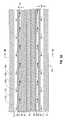
- FIG. 3Ais a longitudinal cross-sectional view of the feedline portion of the microwave energy delivery device of FIG. 2 ;
- FIG. 3Bis a traverse, cross-sectional view taken along line 3 B- 3 B of FIG. 2 ;
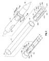
- FIG. 4is a perspective view of the distal portion of the microwave energy delivery device illustrating the coaxial inflow and outflow channels according to the present disclosure
- FIG. 5is an exploded view of the distal portion of the microwave energy delivery device illustrated in FIG. 4 ;
- FIG. 6is a longitudinal cross-sectional view of the distal tip of the microwave energy delivery device.
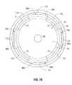
- FIG. 7Ais a transverse, cross-sectional view of the distal tip of the microwave energy delivery device according to one embodiment of the present disclosure
- FIG. 7Bis a transverse, cross-sectional view of the distal tip of the microwave energy delivery device according to another embodiment of the present disclosure.
- FIG. 8is a perspective view of the distal portion of the microwave energy delivery device illustrating the coaxial outflow channel according to the present disclosure
- FIG. 1illustrates a microwave ablation system 10 that includes a microwave energy delivery device 12 , a microwave generator 14 and a cooling fluid supply 33 .
- the microwave energy delivery device 12is coupled to a microwave generator 14 via a flexible coaxial cable 16 and coupled to the cooling fluid supply 33 via cooling fluid supply lines 86 and 88 .
- Cooling fluidexits the microwave energy delivery device 12 through a cooling fluid return line 88 and is discharged in a suitable drain.
- the microwave energy delivery device 12couples to the cooling fluid supply 33 via a cooling fluid return line 88 and cooling fluid is cycled through the cooling fluid supply 33 .
- the cooling fluid return line 88deposits the cooling fluid in a drain or other suitable disposable receptacle and new cooling fluid is provided to the cooling fluids supply from a cooling fluid reservoir 36 or other suitable source of cooling fluid.
- Microwave energy delivery device 12generally includes a connection hub 22 , a feedline 20 and a radiating portion 18 .
- Connection hub 22connects the microwave generator 14 and the cooling fluid supply 33 to the microwave energy delivery device 12 .
- the microwave signalis produced by the microwave generator 14 , transmitted through the flexible coaxial cable 16 , which connects to the connection hub 22 , and the connection hub 22 facilitates the transfer of the microwave energy signal to the feedline 20 .
- Connection hub 22further facilitates the transfer of cooling fluid to and from the feedline 20 . Cooling fluid, provided from the pump 34 of the cooling fluid supply 33 , is provided to the connection hub 22 through the cooling fluid supply line 86 .
- Connection hub 22transfers the cooling fluid from the cooling fluid supply line 86 to the cooling fluid supply lumen (not explicitly shown) of the feedline 20 . Cooling fluid, after being circulated through the feedline 20 and radiating portion 18 of the microwave energy delivery device 12 , is returned to the connection hub 22 through the return lumen (not explicitly shown) of the feedline 20 . Connection hub 22 facilitates the transfer of the cooling fluid from the return lumen (not explicitly shown) to the cooling fluid return line 88 .
- the microwave ablation system 10includes a closed-loop cooling system wherein the cooling fluid return line 88 returns the cooling fluid to the pump 34 of the cooling fluid supply 33 .
- the cooling fluid supply 33cools the returned cooling fluid from the cooling fluid return line 88 before recirculating at least a portion of the returned cooling fluid through the Microwave ablation system 10 .
- cooling fluid return line 88connects to a suitable drain and/or reservoir (e.g., cooling fluid from the microwave energy delivery device 12 is not returned to the cooling fluid supply 33 ).
- Cooling fluid reservoir 36 of the cooling fluid supply 33provides a continuous supply of cooling fluid to the pump 34 .
- Cooling fluid reservoir 36may also include a temperature control system configured to maintain the cooling fluid at a predetermined temperature.
- Coolant fluidmay include any suitable liquid or gas, including air, or any combination thereof.
- the microwave energy delivery device 12may include any suitable microwave antenna 40 such as, for example, a dipole antenna, a monopole antenna and/or a helical antenna.
- the microwave generator 14may be configured to provide any suitable microwave energy signal within an operational frequency from about 300 MHz to about 10 GHz.
- the physical length of the microwave antenna 40is dependant on the frequency of the microwave energy signal generated by the microwave generator 14 .
- a microwave generator 14 providing a microwave energy signal at about 915 MHzdrives a microwave energy delivery device 12 that includes a microwave antenna 40 with a physical length of about 1.6 cm to about 4.0 cm.
- FIG. 2is an enlarged view of the distal portion of the microwave energy delivery device 12 of FIG. 1 and includes a feedline 20 , a proximal radiating portion 42 and a distal radiating portion 44 .
- the proximal radiating portion 42 and the distal radiating portion 44form a dipole microwave antenna 40 .
- proximal radiating portion 42 and the distal radiating portion 44are unequal thereby forming an unbalanced dipole antenna 40 .
- the microwave energy delivery device 12includes a sharpened tip 48 having a tapered end 24 that terminates, in one embodiment, at a pointed end 26 to allow for insertion into tissue with minimal resistance at a distal end of the radiating portion 18 .
- the radiating portion 18is inserted into a pre-existing opening or catheter and the tip may be rounded or flat.
- Sharpened tip 48may be machined from various stock rods to obtain a desired shape.
- the sharpened tip 48may be attached to the distal radiating portion 44 using various adhesives or bonding agents, such as an epoxy sealant. If the sharpened tip 48 is metal, the sharpened tip 48 may be soldered to the distal radiating portion 44 and may radiate electrosurgical energy. In another embodiment, the sharpened tip 48 and a distal radiating portion 44 may be machined as one piece.
- the sharpened tip 48may be formed from a variety of heat-resistant materials suitable for penetrating tissue, such as ceramic, metals (e.g., stainless steel) and various thermoplastic materials, such as polyetherimide, polyimide thermoplastic resins, an example of which is Ultem® sold by General Electric Co. of Fairfield, Conn.
- FIG. 3Ais a longitudinal cross-sectional view of a section of the feedline 20 of the microwave energy delivery device 12 of FIG. 1 and FIG. 3B is a transverse, cross-sectional view of the feedline 20 of the microwave energy delivery device 12 of FIG. 3A .
- Feedline 20is coaxially formed with an inner conductor 50 at the radial center surrounded by a dielectric layer 52 and an outer conductor 56 .
- Inflow hypotube 55is spaced apart and disposed radially outward from the outer conductor 56 .
- the outer surface of the outer conductor 56 b and the inner surface of the inflow hypotube 55 aform an inflow channel 17 i allowing cooling fluid to flow distally through the feedline 20 of the microwave energy delivery device 12 as indicated by cooling fluid inflow arrows 17 i .
- the inflow hypotube 55may be formed from a variety of heat-resistant materials, such as ceramic, metals (e.g., stainless steel), various thermoplastic materials, such as polyetherimide, polyimide thermoplastic resins, an example of which is Ultem® sold by General Electric Co. of Fairfield, Conn., or composite medical tubing, an example of which is PolyMed sold by Polygon of Walkerton, Ind.
- the inflow hypotube 55may have a wall thickness less than about 0.010 inches. In another embodiment, the inflow hypotube 55 may have a wall thickness less than about 0.001 inches.
- the outer hypotube 57is spaced apart from, and radially outward from, the inflow hypotube 55 .
- the outer surface of the inflow hypotube 55 b and the inner surface of the outer hypotube 57 aform an outflow channel 17 o that allows cooling fluid to flow proximately through the feedline 20 of the microwave energy delivery device 12 as indicated by cooling fluid outflow arrows 17 o .
- the outer hypotube 57may be formed from a variety of heat-resistant materials, such as ceramic, metals (e.g., stainless steel), various thermoplastic materials, such as polyetherimide, polyimide thermoplastic resins, an example of which is Ultem® sold by General Electric Co.
- the outer hypotube 57may have a wall thickness less than about 0.010 inches. In another embodiment, the outer hypotube 57 may have a wall thickness less than about 0.001 inches.
- the substantially radially concentric cross-sectional profileprovides uniform flow of fluid in both the inflow channel 17 i and the outflow channel 17 o .
- an inflow channel gap G 1 defined between the outer surface of the outer conductor 56 b and the inner surface of the inflow hypotube 55 ais substantially uniform around the circumference of the outer conductor 56 .
- an outflow channel gap G 2 defined between the outer surface of the inflow hypotube 55 b and the inner surface of the outer hypotube 57is substantially uniform around the circumference of the inflow hypotube 55 .
- the cross-sectional area of the inflow channel 17 i and the outflow channel 17 ois the difference between the area at the outer surface of each channels 17 i , 17 o (i.e., the area at the inner diameter of the inflow hypotube 55 and the area at the inner diameter of the outer hypotube 57 , respectively) and the area at the inner surface of the each channels 17 i , 17 o (i.e., the area at the outer diameter of the outer conductor 56 and the area at the outer diameter of the inflow hypotube 55 ).
- the cross-sectional area of the inflow channel 17 i and the outflow channel 17 ois substantially uniform along the longitudinal length of the feedline 20 .
- transverse shifting of the inflow hypotube 55 within the outer hypotube 57 or transverse shifting of the outer conductor 56 within the inflow hypotube 55may create a non-uniform inflow or outflow channel gap G 1 , G 2 , but will not affect the cross-sectional area of either inflow channel 17 i and/or outflow channel 17 o.
- FIG. 4(illustrating in partial assembly the radiating portion 18 of FIG. 1 ) further illustrates the inflow fluid flow pathways.
- the radiating portion 18is formed by inserting the distal portion of the feedline 20 into the microwave antenna 40 .
- the feedline 20is configured to provide cooling fluid and a microwave energy signal to the microwave antenna 40 . As discussed hereinabove, the feedline 20 provides cooling fluid through the inflow channel 17 i formed between the inflow hypotube 55 and the outer conductor 56 of the feedline 20 . The feedline 20 also provides a microwave energy signal between the inner conductor 50 and the outer conductor 56 .
- the microwave antenna 40includes a tapered inflow transition collar 53 , a channeled puck 46 , a distal radiating portion 44 , including a plurality of antenna sleeve stops 68 a - 68 d , and a sharpened tip 48 .
- the feedline 20when inserted into the microwave antenna 40 , connects the outer conductor 56 to the tapered inflow transition collar 53 and the inner conductor 50 to the distal radiating portion 44 .
- FIG. 5is an exploded view of the microwave antenna 40 of FIG. 4 that further illustrates the components of the microwave assembly.
- the tapered inflow transition collar 53includes an outer taper 60 a , a middle taper 60 b and an inner taper 60 c and is configured to transition the cooling fluid from the inflow channel 17 i to various fluid channels formed in the microwave antenna 40 as discussed hereinbelow.
- the distal end of the feedline 20is inserted into the proximal end of the tapered inflow transition collar 53 .
- Each component 50 , 52 , 55 , 56 of the feedline 20is cut to a specific length such that when the feedline 20 is inserted each component ends at a predetermined position within the microwave antenna assembly 40 .
- the inflow hypotube 55(See FIG. 4 ) is inserted into the proximal end of the outer taper 60 a portion of the tapered inflow transition collar 53 .
- the transition between the outer taper 60 a and the middle taper 60 bforms a mechanical stop for the inflow hypotube 55 .
- Outer taper 60 a and inflow hypotube 55forms a fluid-tight seal therebetween thereby limiting cooling fluid to the middle taper 60 b of the tapered inflow transition collar 53 .
- the fluid-tight seal between the inflow hypotube 55 and the outer taper 60 amay be formed by adhesive, epoxy, or a polytetrafluoroethylene or other suitable sealant, or fluid-tight seal may be formed by a tight mechanical connection between the inflow hypotube 55 and the outer taper 60 a.
- the inflow hypotube 55is formed of a conductive metal such as, for example, stainless steel, steel, copper or any other suitable metal, and the fluid-tight seal insulates the inflow hypotube 55 and the inner surface of the tapered inflow transition collar 53 .
- the fluid tight sealmay include one or more insulating materials that forms a dielectric barrier between the inflow hypotube 55 and tapered inflow transition collar 53 .
- the outer conductor 56 when inserted into the proximal end of the outer taper 60 aextends through the middle taper 60 b with at least a portion of the outer conductor 56 connecting to the inner taper 60 c .
- the outer conductor 56 and inner taper 60 cform an electrical connection therebetween such that microwave energy signal provided by the outer conductor 56 conducts to the tapered inflow transition collar 53 such that the tapered inflow transition collar 53 forms at least a portion of the proximal radiating portion 42 of the microwave antenna 40 .
- the outer surface of the inflow hypotube 55 and the inner surface of the outer taper 60 aform a fluid-tight seal therebetween, Fluid exits the inflow channel 17 i and is deposited in the open area formed within the middle taper 60 b .
- the outer surface of the outer conductor 56 and inner surface of the inner taper 60 cform a fluid-tight seal therebetween, thereby preventing the cooling fluid from traveling distal of the middle taper 60 b within the tapered inflow transition collar 53 .
- an electrical connectionis formed between the outer conductor 56 and the inner taper 60 c of the tapered inflow transition collar 53 .
- tapered inflow transition collar 53forms at least a portion of the proximal radiating portion 42 of the radiating portion 18 , wherein the radiating portion 18 is a dipole antenna.
- the electrical connection between the outer conductor 56 and the inner taper 60 cmay include all of the contact surface therebetween or the electrical connection may include only a portion thereof.
- the electrical connection between the outer conductor 56 and the inner taper 60 cis formed circumferentially along the distal portion of the inner taper 60 c and the remaining portion of the contact surface insulates the outer conductor 56 and the inner taper 60 c.
- the fluid-tight seal between the outer conductor 56 and the inner taper 60 cforms an insulating barrier therebetween and the tapered inflow transition collar 53 does not form a portion of the radiating portion 18 , wherein the radiating portion 18 is a monopolar antenna.
- the fluid-tight seal between the outer conductor 56 and the inner taper 60 cforms an insulating barrier therebetween.
- An electrical connection between the outer conductor 56 and the inner taper 60 eis formed by connecting a distal end of the outer conductor 56 or the inner taper 60 e to one another.
- pressurebuilds and the cooling fluid exits the middle taper 60 b through one of the plurality of cooling fluid transition apertures 53 a - 53 d formed in the tapered inflow transition collar 53 .
- the cooling fluidflows radially outward through one of the plurality of cooling fluid transition apertures 53 a - 53 d formed in the middle taper 60 b , the cooling fluid flows distally along the outer surface of the middle taper 60 b between the tapered inflow transition collar 53 and the antenna sleeve 2 .
- Antenna sleeve 2forms a fluid-tight seal with the outer taper 60 a of the tapered inflow transition collar 53 thereby requiring fluid to flow distally toward the channeled puck 46 .
- the antenna sleeve 2is a thin polyimide sleeve, or other suitable non-conductive material that has little or no impact on the transmission and/or delivery of microwave radiation.
- cooling fluid exiting one of the plurality of cooling fluid transition apertures 53 a - 53 dflows distally along the outer surface of the tapered inflow transition collar 53 , the outer surface of the channeled puck 46 and the outer surface of the distal radiating portion 44 and along the inner surface of the antenna sleeve 2 .
- Proximal end of antenna sleeve 2forms a fluid-tight seal with the outer taper 60 a of the tapered inflow transition collar 53 .
- the proximal end 2 a of the antenna sleeve 2mates with a proximal antenna sleeve stop 53 s formed in the outer taper 60 a such that the outer diameter of the antenna sleeve 2 and the outer diameter of the outer taper 60 a are substantially identical.
- a channel 67 a , 67 b , 67 c , 67 dis formed between each of the adjacent raised portions 66 a - 66 d wherein the radial outer surface of the channeled puck 46 at the raised portion 66 a - 66 d is radially outward from the outer surface of the channeled puck 46 at each of the channels 67 a - 67 d .
- Channels 67 a - 67 dare configured to form a cooling fluid pathway between the outer surface of the channeled puck 46 and the inner surface of the antenna sleeve 2 .
- cooling fluidexits the middle taper 60 b of the tapered inflow transition collar 53 , flows distal through the plurality of channels 67 a - 67 d formed between the raised portions 66 a - 66 d of the channeled puck 46 and the antenna sleeve 2 and is deposited on the outer surface of the distal radiating portion 44 .
- the cooling fluidis deposited into a gap formed between the outer surface of the proximal end 2 a of the distal radiating portion 44 and the inner surface of the antenna sleeve 2 .
- Distal end 2 b of the distal radiating portion 44includes a plurality of antenna sleeve stops 68 a - 68 d .
- Adjacent antenna sleeve stops 68 a - 68 dare spaced apart from each other and form a plurality of distal flow channels 70 a - 70 d therebetween.
- Distal end 2 b of antenna sleeve 2is configured to abut a distal lip 69 a - 69 d formed on the distal end of each of the respective antenna sleeve stops 68 a - 68 d.
- the distal end of the outer jacket 43forms a fluid tight seal with a proximal portion of the sharpened tip 48 .
- a fluid-tight sealis formed between the outer jacket 43 and the sharpened tip 48 , wherein the fluid-tight seal is distal the distal end 2 b of the antenna sleeve 2 .
- the antenna sleeve 2is contained within the outer jacket 43 and at least a portion of the outflow channel 17 o is formed between the inner surface of the outer jacket 43 and the outer surface of the antenna sleeve 2 .
- the distal lip 69 a - 69 d of the respective antenna sleeve stops 68 a - 68 dextend radially outward from the outer surface of the antenna sleeve 2 and space the outer jacket 43 from the outer surface of the antenna sleeve 2 .
- a gapis formed between the antenna sleeve 2 and the outer jacket 43 that forms at least a portion of the outflow channel 17 o .
- the plurality of circumferentially-spaced sleeve stops 68 a - 68 duniformly position the outer jacket 43 with respect to the antenna sleeve 2 .
- FIG. 5is an exploded view of a portion of the radiating portion 18 illustrated in FIG. 4 including the tapered inflow transition collar 53 , the channeled puck 46 , the distal radiating portion 44 , the antenna sleeve 2 and the sharpened tip 48 .
- the channeled puck 46is positioned between the tapered inflow transition collar 53 and the distal radiating portion 44 .
- the antenna sleeve 2is also positioned between a portion of the tapered inflow transition collar 53 and the distal radiating portion 44 ; the antenna sleeve 2 being spaced radially outward from the channeled puck 46 .
- the tapered inflow transition collar 53includes an outer taper 60 a , a middle taper 60 b and an inner taper 60 c .
- a portion of the outer surface of the outer taper 60 amay form a proximal antenna sleeve stop 53 s configured to receive the proximal end of the antenna sleeve 2 .
- Outer taper 60 ais configured to slide over the distal end of the inflow hypotube 55 .
- Inflow hypotube 55may abut the transition portion between the outer taper 60 a and the middle taper 60 b .
- Fluid-tight sealsformed between the inflow hypotube 55 and the outer taper 60 a and between the outer conductor 56 and the inner taper 60 c , force the cooling fluid traveling distally through in inflow channel 17 i (formed between outer surface of the outer conductor 56 and the inner surface of the inflow hypotube 55 , see FIG. 3A ) to be deposited into the middle taper 60 b of the tapered inflow transition collar 53 .
- the fluid-tight seal between the tapered inflow transition collar 53 and the inflow hypotube 55is formed by a press-fit connection therebetween.
- the inflow hypotube 55may be press-fit over the tapered inflow transition collar 53 or the tapered inflow transition collar 53 may be press-fit over the inflow hypotube 55 , as illustrated in FIGS. 2 , 4 and 8 .
- the outer diameters of the outer taper 60 a , a middle taper 60 b and an inner taper 60 c , D 1 , D 2 , D 3 , respectively, and the thickness of each taper 60 a - 60 care configured to facilitate the assembly of components that form the microwave energy delivery device 12 .
- the diameter D 1 and thickness of the outer taper 60 ais selected such that the inflow hypotube 55 forms a fluid-tight seal with the inner surface of the outer taper 60 a and the antenna sleeve 2 forms a fluid-tight seal with the outer diameter of the outer taper 60 a .
- the diameter D 2 of the middle taper 60 bis selected to provide an adequate gap between the outer conductor 56 and the antenna sleeve 2 and to facilitate fluid flow through the middle taper 60 b .
- the diameter D 3 and thickness of the inner taper 60 cis selected such that the outer conductor 56 forms a fluid tight seal with the inner surface of the inner taper 60 c and the channeled puck 46 forms a fluid-tight seal with the outer diameter of the inner taper 60 c.
- the three tiers of the tapered inflow transition collar 53are configured to facilitate the transition of cooling fluid between a first portion of the inflow channel 17 i (radially formed in a first portion of the coaxially configured structure) and a second channel portion of the inflow channel 17 i (radially formed in a second portion of the coaxially configured structure).
- a first portion of the inflow channel 17 iis formed between the outer surface of the outer conductor 56 and the inner surface of the inflow hypotube 55 and at a point distal to the tapered inflow transition collar 53
- a second portion of the inflow channel 17 iis formed between the antenna sleeve 2 and the channeled puck 46 .
- the tapered inflow transition collar 53facilitates the transition of fluid from a first portion of the inflow channel 17 i formed at a first radial distance from the radial center of the microwave energy delivery device 12 to a second portion of the inflow channel 17 i formed at a second radial distance from the radial center of the microwave energy delivery device 12 .
- the first and second radial distances from the radial center of the microwave energy delivery device 12may or may not be equal.
- the proximal end of the channeled puck 46is configured to receive at least a portion of the inner taper 60 c of the tapered inflow transition collar 53 and forms a fluid-tight seal therebetween and the distal end of the channeled puck 46 is configured to receive at least a portion of the distal radiating portion 44 .
- the inner conductor(not explicitly shown) extends through the radial center of the channeled puck 46 and is received by the distal radiating portion 44 .
- the channeled puck 46is injection molded during the manufacturing process to form a water-tight seal around a portion of the outer conductor 56 and/or a portion of the tapered inflow transition collar 53 .
- the channeled puck 46is press-fit over a portion of the outer conductor and/or a portion of the tapered inflow transition collar 53 and forms a fluid-tight seal therebetween.
- the distal radiating portion 44includes a conductive member that may be formed from any type of conductive material, such as metals (e.g., copper, stainless steel, tin, and various alloys thereof).
- the distal radiating portion 44may have a solid structure and may be formed from solid wire (e.g., 10 AWG).
- the distal radiating portion 44may be formed from a hollow sleeve of an outer conductor 56 of the coaxial cable or another cylindrical conductor.
- the cylindrical conductormay then be filled with solder to convert the cylinder into a solid shaft. More specifically, the solder may be heated to a temperature sufficient to liquefy the solder within the cylindrical conductor (e.g., 500° F.) thereby creating a solid shaft.
- the radially-outward surface of the channeled puck 46includes a plurality of raised portions 66 a - 66 d and/or a plurality of recessed portions that form the channels 67 a - 67 d .
- the plurality of raised portions 66 a - 66 dare configured to slideably engage the antenna sleeve 2 and form a plurality of inflow channels 17 i defined between the recessed portions and the inner surface of the antenna sleeve 2 .
- Antenna sleeve 2is configured to surround the channeled puck 46 and surround at least a portion of the distal radiating portion 44 .
- the proximal end portion of the antenna sleeve 2connects to the proximal antenna sleeve stop 53 s (formed in a portion of the outer taper 60 a ) and the distal end portion of the antenna sleeve 2 connects to the distal antenna sleeve stops 68 a - 68 d formed in the distal radiating portion 44 .
- a electrical connection between the distal radiating portion 44 and the inner conductormay be formed through access slot 70 .
- the access slot 70may be filled with a suitable electrically conductive material and an electrical connection may be formed between the distal radiating portion 44 and the inner conductor (not explicitly shown). Distal end of the distal radiating portion 44 may connect to sharpened tip 48 or may form the sharpened tip 48 .
- the inflow channel 17 i and the outflow channel 17 oare illustrated in FIGS. 4 and 6 .
- Cooling fluidflows distally through the distal flow channels 70 a - 70 d formed between adjacent antenna sleeve stops 68 a - 68 d .
- the fluidis deposited in a fluid transition chamber 117 formed between the distal radiating portion 44 and the outer jacket 43 .
- a fluid-tight seal, framed between the outer jacket 43 and the sharpened tip 48prevents fluid from flowing distal the fluid transition chamber 117 .
- cooling fluid in the fluid transition chamber 117exits the fluid transition chamber 117 and flows proximally and into the outflow channel 17 o formed between the outer surface of the antenna sleeve 2 and the inner surface of the outer jacket 43 .
- the radially outward portion of the distal lip 69 a - 69 d formed on the distal end of each of the respective antenna sleeve stops 68 a - 68 dmay form additional channels between the distal lips 69 a - 69 d and the outer jacket 43 to allow the cooling fluid to flow proximally from the fluid transition chamber 117 .
- the distal portion of the outflow channel 17 ois illustrated in FIG. 8 .
- the outer jacket 43forms the outer boundary of the outflow channel 170 in the distal portion of the microwave energy delivery device 12 .
- the distal end of the outer jacket 43forms a fluid tight seal with the sharpened tip 48 and/or the distal radiating portion 44 and the proximal end forms a fluid tight seal with a portion of the outer hypotube 57 proximal the fluid outflow slots 57 a , 57 b ( 57 c , 57 d not shown).
- Outer hypotube 57may further include a proximal outer jacket stop 57 s that provides a smooth transition on the outer surface of the microwave energy delivery device 12 between the outer hypotube 57 and the outer jacket.
- a portion of the outflow channel 17 ois formed between the interior surface of the outer jacket 43 and at least a portion of the antenna sleeve 2 , a portion of the tapered inflow transition collar 53 , a portion of the choke dielectric 19 , a portion of the EMF shield 28 that covers the core choke (not shown) and a portion of the outer hypotube 57 .
- the coaxial arrangement of the outflow channel 17 oprovides for the uniform application of cooling fluid to the distal portion of the microwave energy delivery device 12 .
- the fluid-tight seal between the outer jacket 43 and the outer hypotube 57directs the cooling fluid to travel through the fluid outflow slots 57 a , 57 b ( 57 c , 57 d not explicitly shown) and into the portion of the outflow channel 17 o formed between the interior surface of the outer hypotube 57 and the outer surface of the inflow hypotube 55 , as illustrated in FIG. 3A and described hereinabove.
- the microwave energy delivery devices 12includes a substantially coaxially arrangement through the length.
- Various layers of the microwave energy delivery device 12form a substantially coaxial arrangement of the inflow channel 17 i and a substantially coaxial arrangement of the outflow channel 17 o between two (or more) of the coaxial layers.
- the substantially coaxial inflow and outflow channels 17 i , 17 ocoaxially distribute the cooling fluid and thereby provides even cooling throughout the microwave energy delivery device 12 .
- Various structures in the microwave energy delivery device 12facilitate the transition of the cooling fluid between the various sections of the inflow and outflow channels 17 i , 17 o respectively, while maintaining a substantially coaxial arrangement throughout the device.
- the tapered inflow transition collar 53transitions the cooling fluid from inflow channel 17 i formed between the outer conductor 56 and inflow hypotube 55 and an inflow channel 17 i formed between the antenna sleeve 2 and the tapered inflow transition collar 53 , the channeled puck 46 and the distal radiating portion 44 .
- the fluid outflow slots 57 a - 57 d formed in the outer hypotube 57directs the cooling fluid from outflow channel 17 o formed between the EMF shield 28 and the outer jacket 43 and an outflow channel 17 o formed between the inflow hypotube 55 and the outer hypotube 57 .
- the cooling fluidmaintains a substantially coaxial arrangement along the length of the microwave energy delivery device 12 .
- the microwave energy delivery device 12facilitates the substantially coaxial fluid flow while supporting the coaxial arrangement.
- the raised portions 66 a of the channeled puck 46 , the outer taper 60 a of the tapered inflow transition collar 53 and the distal portions of the antenna sleeve stops 68 a - 68 dposition the antenna sleeve 2 in substantially coaxial arrangement while forming a portion of the inflow channel 17 i therebetween.
- the sharpened tip 48 , the distal portions of the antenna sleeve stops 68 a - 68 d and the inflow hypotube 55position the outer jacket 43 in substantially coaxial arrangement while forming a portion of the outflow channel 17 o therebetween.
Landscapes
- Health & Medical Sciences (AREA)
- Surgery (AREA)
- Life Sciences & Earth Sciences (AREA)
- Biomedical Technology (AREA)
- Medical Informatics (AREA)
- Nuclear Medicine, Radiotherapy & Molecular Imaging (AREA)
- Electromagnetism (AREA)
- Engineering & Computer Science (AREA)
- Physics & Mathematics (AREA)
- Heart & Thoracic Surgery (AREA)
- Otolaryngology (AREA)
- Molecular Biology (AREA)
- Animal Behavior & Ethology (AREA)
- General Health & Medical Sciences (AREA)
- Public Health (AREA)
- Veterinary Medicine (AREA)
- Surgical Instruments (AREA)
Abstract
Description
Claims (18)
Priority Applications (12)
| Application Number | Priority Date | Filing Date | Title |
|---|---|---|---|
| US13/118,929US8992413B2 (en) | 2011-05-31 | 2011-05-31 | Modified wet tip antenna design |
| AU2012203168AAU2012203168B2 (en) | 2011-05-31 | 2012-05-29 | Modified wet tip antenna design |
| CA2778457ACA2778457C (en) | 2011-05-31 | 2012-05-29 | Modified wet tip antenna design |
| JP2012121524AJP6140395B2 (en) | 2011-05-31 | 2012-05-29 | Improved design of wet chip antenna |
| EP17199371.0AEP3308733B1 (en) | 2011-05-31 | 2012-05-30 | Modified wet tip antenna design |
| EP12004169.4AEP2529688B1 (en) | 2011-05-31 | 2012-05-30 | Modified wet tip antenna design |
| EP15177918.8AEP2965705B1 (en) | 2011-05-31 | 2012-05-30 | Modified wet tip antenna design |
| CN201210319428.3ACN102846376B (en) | 2011-05-31 | 2012-05-31 | Improved Wet Tip Antenna Design |
| CN201510955637.0ACN105361949B (en) | 2011-05-31 | 2012-05-31 | Improved wet tip antenna design |
| US14/674,276US10588693B2 (en) | 2011-05-31 | 2015-03-31 | Modified wet tip antenna design |
| JP2017091105AJP2017176841A (en) | 2011-05-31 | 2017-05-01 | Modified wet tip antenna design |
| JP2019212326AJP2020036975A (en) | 2011-05-31 | 2019-11-25 | Improved wet tip antenna design |
Applications Claiming Priority (1)
| Application Number | Priority Date | Filing Date | Title |
|---|---|---|---|
| US13/118,929US8992413B2 (en) | 2011-05-31 | 2011-05-31 | Modified wet tip antenna design |
Related Child Applications (1)
| Application Number | Title | Priority Date | Filing Date |
|---|---|---|---|
| US14/674,276ContinuationUS10588693B2 (en) | 2011-05-31 | 2015-03-31 | Modified wet tip antenna design |
Publications (2)
| Publication Number | Publication Date |
|---|---|
| US20120310228A1 US20120310228A1 (en) | 2012-12-06 |
| US8992413B2true US8992413B2 (en) | 2015-03-31 |
Family
ID=46318796
Family Applications (2)
| Application Number | Title | Priority Date | Filing Date |
|---|---|---|---|
| US13/118,929Active2033-11-07US8992413B2 (en) | 2011-05-31 | 2011-05-31 | Modified wet tip antenna design |
| US14/674,276Active2032-12-03US10588693B2 (en) | 2011-05-31 | 2015-03-31 | Modified wet tip antenna design |
Family Applications After (1)
| Application Number | Title | Priority Date | Filing Date |
|---|---|---|---|
| US14/674,276Active2032-12-03US10588693B2 (en) | 2011-05-31 | 2015-03-31 | Modified wet tip antenna design |
Country Status (6)
| Country | Link |
|---|---|
| US (2) | US8992413B2 (en) |
| EP (3) | EP2965705B1 (en) |
| JP (3) | JP6140395B2 (en) |
| CN (2) | CN102846376B (en) |
| AU (1) | AU2012203168B2 (en) |
| CA (1) | CA2778457C (en) |
Cited By (7)
| Publication number | Priority date | Publication date | Assignee | Title |
|---|---|---|---|---|
| US10022186B2 (en) | 2008-08-28 | 2018-07-17 | Covidien Lp | Microwave antenna with cooled handle |
| US10271902B2 (en) | 2012-01-06 | 2019-04-30 | Covidien Lp | System and method for treating tissue using an expandable antenna |
| US10405918B2 (en) | 2012-04-30 | 2019-09-10 | Covidien Lp | Limited reuse ablation needles and ablation devices for use therewith |
| US10588693B2 (en) | 2011-05-31 | 2020-03-17 | Covidien Lp | Modified wet tip antenna design |
| US10631922B2 (en) | 2008-02-07 | 2020-04-28 | Covidien Lp | Endoscopic instrument for tissue identification |
| US20200297420A1 (en)* | 2011-12-21 | 2020-09-24 | Neuwave Medical, Inc. | Energy delivery systems and uses thereof |
| US12329436B2 (en) | 2019-12-03 | 2025-06-17 | Bard Peripheral Vascular, Inc. | Cauterization device for sealing pleural layers |
Families Citing this family (36)
| Publication number | Priority date | Publication date | Assignee | Title |
|---|---|---|---|---|
| US10363092B2 (en) | 2006-03-24 | 2019-07-30 | Neuwave Medical, Inc. | Transmission line with heat transfer ability |
| US10376314B2 (en) | 2006-07-14 | 2019-08-13 | Neuwave Medical, Inc. | Energy delivery systems and uses thereof |
| US11389235B2 (en) | 2006-07-14 | 2022-07-19 | Neuwave Medical, Inc. | Energy delivery systems and uses thereof |
| US8246615B2 (en) | 2009-05-19 | 2012-08-21 | Vivant Medical, Inc. | Tissue impedance measurement using a secondary frequency |
| US8292881B2 (en) | 2009-05-27 | 2012-10-23 | Vivant Medical, Inc. | Narrow gauge high strength choked wet tip microwave ablation antenna |
| EP3549544B1 (en) | 2009-07-28 | 2021-01-06 | Neuwave Medical, Inc. | DEVICE FOR ABLATION |
| ES2856026T3 (en) | 2010-05-03 | 2021-09-27 | Neuwave Medical Inc | Power supply systems |
| US8888771B2 (en) | 2011-07-15 | 2014-11-18 | Covidien Lp | Clip-over disposable assembly for use with hemostat-style surgical instrument and methods of manufacturing same |
| US9119650B2 (en) | 2013-03-15 | 2015-09-01 | Covidien Lp | Microwave energy-delivery device and system |
| US9161814B2 (en) | 2013-03-15 | 2015-10-20 | Covidien Lp | Microwave energy-delivery device and system |
| US9301723B2 (en) | 2013-03-15 | 2016-04-05 | Covidien Lp | Microwave energy-delivery device and system |
| US9987087B2 (en)* | 2013-03-29 | 2018-06-05 | Covidien Lp | Step-down coaxial microwave ablation applicators and methods for manufacturing same |
| CN104027168A (en)* | 2014-06-20 | 2014-09-10 | 章建全 | Microwave ablation needle antenna with infusion structure for curing cyst |
| CN113367788B (en) | 2015-10-26 | 2024-09-06 | 纽韦弗医疗设备公司 | Energy delivery systems and uses thereof |
| US10524797B2 (en) | 2016-01-13 | 2020-01-07 | Covidien Lp | Adapter assembly including a removable trocar assembly |
| US10813692B2 (en) | 2016-02-29 | 2020-10-27 | Covidien Lp | 90-degree interlocking geometry for introducer for facilitating deployment of microwave radiating catheter |
| US10856940B2 (en)* | 2016-03-02 | 2020-12-08 | Covidien Lp | Ablation antenna including customizable reflectors |
| CN105769338A (en)* | 2016-04-11 | 2016-07-20 | 上海大学 | Microwave ablation probe for interventional therapy of liver cancer |
| US10531917B2 (en) | 2016-04-15 | 2020-01-14 | Neuwave Medical, Inc. | Systems and methods for energy delivery |
| CN105816240B (en)* | 2016-05-24 | 2018-09-28 | 赛诺微医疗科技(浙江)有限公司 | For the antenna module of microwave ablation and using its microwave melt needle |
| PL3360496T3 (en)* | 2017-02-10 | 2022-06-06 | Erbe Elektromedizin Gmbh | Fluid connection device and cryosurgical probe having same |
| WO2018165810A1 (en)* | 2017-03-13 | 2018-09-20 | Covidien Lp | Inflow and outflow control of a closed cooling system |
| CN107260301B (en)* | 2017-04-20 | 2021-04-02 | 南通融锋医疗科技有限公司 | True circle microwave ablation antenna and system |
| CN107260302A (en)* | 2017-04-20 | 2017-10-20 | 南京维京九洲医疗器械研发中心 | Curved microwave ablation aciculiform antenna for treating fibroid |
| CN107252351A (en)* | 2017-04-20 | 2017-10-17 | 南京维京九洲医疗器械研发中心 | The microwave melt needle treated for thyroid tumors |
| CN107115146A (en)* | 2017-04-20 | 2017-09-01 | 南京维京九洲医疗器械研发中心 | With the tumour Microwave Coagulation Therapy aciculiform antenna for taking out fluid-filling structure |
| MX2020000162A (en)* | 2017-07-05 | 2020-07-22 | Commscope Technologies Llc | Base station antennas having radiating elements with sheet metal-on dielectric dipole radiators and related radiating elements. |
| US11672596B2 (en) | 2018-02-26 | 2023-06-13 | Neuwave Medical, Inc. | Energy delivery devices with flexible and adjustable tips |
| CN111293418A (en) | 2018-12-10 | 2020-06-16 | 康普技术有限责任公司 | Radiator assemblies and base station antennas for base station antennas |
| US11832879B2 (en) | 2019-03-08 | 2023-12-05 | Neuwave Medical, Inc. | Systems and methods for energy delivery |
| CN112723462B (en)* | 2019-10-28 | 2024-10-25 | 陕西青朗万城环保科技有限公司 | Microwave radiator and system |
| EP4094691A4 (en) | 2020-03-04 | 2024-02-28 | Canon Kabushiki Kaisha | X-RAY SYSTEM, CONTROL DEVICE AND METHOD FOR CONTROLLING AN X-RAY SYSTEM |
| CN111603239B (en)* | 2020-04-22 | 2023-06-02 | 哈尔滨医科大学 | A microwave device for tumor ablation therapy |
| CN111568540B (en)* | 2020-05-26 | 2021-05-04 | 南京德文医学科技有限公司 | An integrated microwave ablation needle and its assembly process |
| GB202119001D0 (en) | 2021-12-24 | 2022-02-09 | Creo Medical Ltd | Surgical instrument |
| CN114469310B (en)* | 2022-03-25 | 2022-07-29 | 天津市鹰泰利安康医疗科技有限责任公司 | Electrode control system for irreversible electroporation equipment |
Citations (159)
| Publication number | Priority date | Publication date | Assignee | Title |
|---|---|---|---|---|
| DE390937C (en) | 1922-10-13 | 1924-03-03 | Adolf Erb | Device for internal heating of furnace furnaces for hardening, tempering, annealing, quenching and melting |
| DE1099658B (en) | 1959-04-29 | 1961-02-16 | Siemens Reiniger Werke Ag | Automatic switch-on device for high-frequency surgical devices |
| FR1275415A (en) | 1960-09-26 | 1961-11-10 | Device for detecting disturbances for electrical installations, in particular electrosurgery | |
| DE1139927B (en) | 1961-01-03 | 1962-11-22 | Friedrich Laber | High-frequency surgical device |
| DE1149832B (en) | 1961-02-25 | 1963-06-06 | Siemens Reiniger Werke Ag | High frequency surgical apparatus |
| FR1347865A (en) | 1962-11-22 | 1964-01-04 | Improvements to diathermo-coagulation devices | |
| DE1439302A1 (en) | 1963-10-26 | 1969-01-23 | Siemens Ag | High-frequency surgical device |
| SU401367A1 (en) | 1971-10-05 | 1973-10-12 | Тернопольский государственный медицинский институт | BIAKTIVNYE ELECTRO SURGICAL INSTRUMENT |
| DE2439587A1 (en) | 1973-08-23 | 1975-02-27 | Matburn Holdings Ltd | ELECTROSURGICAL DEVICE |
| DE2455174A1 (en) | 1973-11-21 | 1975-05-22 | Termiflex Corp | INPUT / OUTPUT DEVICE FOR DATA EXCHANGE WITH DATA PROCESSING DEVICES |
| DE2407559A1 (en) | 1974-02-16 | 1975-08-28 | Dornier System Gmbh | Tissue heat treatment probe - has water cooling system which ensures heat development only in treated tissues |
| DE2415263A1 (en) | 1974-03-29 | 1975-10-02 | Aesculap Werke Ag | Surgical H.F. coagulation probe has electrode tongs - with exposed ends of insulated conductors forming tong-jaws |
| DE2429021A1 (en) | 1974-06-18 | 1976-01-08 | Erbe Elektromedizin | Remote control for HF surgical instruments - uses cable with two conductors at most |
| FR2235669B1 (en) | 1973-07-07 | 1976-05-07 | Lunacek Boris | |
| DE2460481A1 (en) | 1974-12-20 | 1976-06-24 | Delma Elektro Med App | Electrode grip for remote HF surgical instrument switching - has shaped insulated piece with contact ring of sterilizable (silicon) rubber |
| DE2602517A1 (en) | 1975-01-23 | 1976-07-29 | Dentsply Int Inc | ELECTROSURGICAL DEVICE |
| DE2504280A1 (en) | 1975-02-01 | 1976-08-05 | Hans Heinrich Prof Dr Meinke | DEVICE FOR ELECTRIC TISSUE CUTTING IN SURGERY |
| DE2627679A1 (en) | 1975-06-26 | 1977-01-13 | Marcel Lamidey | HEMATISTIC HIGH FREQUENCY EXTRACTOR FORCEPS |
| DE2540968A1 (en) | 1975-09-13 | 1977-03-17 | Erbe Elektromedizin | Circuit for bipolar coagulation tweezers - permits preparation of tissues prior to coagulation |
| FR2276027B3 (en) | 1974-06-25 | 1977-05-06 | Medical Plastics Inc | |
| DE2820908A1 (en) | 1977-05-16 | 1978-11-23 | Joseph Skovajsa | DEVICE FOR THE LOCAL TREATMENT OF A PATIENT IN PARTICULAR FOR ACUPUNCTURE OR AURICULAR THERAPY |
| DE2803275A1 (en) | 1978-01-26 | 1979-08-02 | Aesculap Werke Ag | HF surgical appts. with active treatment and patient electrodes - has sensor switching generator to small voltage when hand-operated switch is closed |
| DE2823291A1 (en) | 1978-05-27 | 1979-11-29 | Rainer Ing Grad Koch | Coagulation instrument automatic HF switching circuit - has first lead to potentiometer and second to transistor base |
| SU727201A2 (en) | 1977-11-02 | 1980-04-15 | Киевский Научно-Исследовательский Институт Нейрохирургии | Electric surgical apparatus |
| FR2313708B1 (en) | 1975-06-02 | 1980-07-04 | Sybron Corp | |
| DE2946728A1 (en) | 1979-11-20 | 1981-05-27 | Erbe Elektromedizin GmbH & Co KG, 7400 Tübingen | HF surgical appts. for use with endoscope - provides cutting or coagulation current at preset intervals and of selected duration |
| USD263020S (en) | 1980-01-22 | 1982-02-16 | Rau Iii David M | Retractable knife |
| DE3143421A1 (en) | 1980-11-04 | 1982-05-27 | The Agency of Industrial Science and Technology, Tokyo | Laser scalpel |
| DE3045996A1 (en) | 1980-12-05 | 1982-07-08 | Medic Eschmann Handelsgesellschaft für medizinische Instrumente mbH, 2000 Hamburg | Electro-surgical scalpel instrument - has power supply remotely controlled by surgeon |
| USD266842S (en) | 1980-06-27 | 1982-11-09 | Villers Mark W | Phonograph record spacer |
| FR2517953A1 (en) | 1981-12-10 | 1983-06-17 | Alvar Electronic | Diaphanometer for optical examination of breast tissue structure - measures tissue transparency using two plates and optical fibre bundle cooperating with photoelectric cells |
| USD278306S (en) | 1980-06-30 | 1985-04-09 | Mcintosh Lois A | Microwave oven rack |
| FR2502935B1 (en) | 1981-03-31 | 1985-10-04 | Dolley Roger | METHOD AND DEVICE FOR CONTROLLING THE COAGULATION OF TISSUES USING A HIGH FREQUENCY CURRENT |
| US4658836A (en) | 1985-06-28 | 1987-04-21 | Bsd Medical Corporation | Body passage insertable applicator apparatus for electromagnetic |
| FR2573301B3 (en) | 1984-11-16 | 1987-04-30 | Lamidey Gilles | SURGICAL PLIERS AND ITS CONTROL AND CONTROL APPARATUS |
| DE3120102C2 (en) | 1981-05-20 | 1987-08-20 | Fischer Met Gmbh, 7800 Freiburg, De | |
| EP0246350A1 (en) | 1986-05-23 | 1987-11-25 | Erbe Elektromedizin GmbH. | Coagulation electrode |
| DE8712328U1 (en) | 1987-09-11 | 1988-02-18 | Jakoubek, Franz, 7201 Emmingen-Liptingen | Endoscopy forceps |
| USD295894S (en) | 1985-09-26 | 1988-05-24 | Acme United Corporation | Disposable surgical scissors |
| USD295893S (en) | 1985-09-25 | 1988-05-24 | Acme United Corporation | Disposable surgical clamp |
| DE3711511C1 (en) | 1987-04-04 | 1988-06-30 | Hartmann & Braun Ag | Method for determining gas concentrations in a gas mixture and sensor for measuring thermal conductivity |
| DE3510586C2 (en) | 1985-03-23 | 1988-07-28 | Erbe Elektromedizin Gmbh, 7400 Tuebingen, De | |
| JPH055106Y2 (en) | 1986-02-28 | 1993-02-09 | ||
| DE4238263A1 (en) | 1991-11-15 | 1993-05-19 | Minnesota Mining & Mfg | Adhesive comprising hydrogel and crosslinked polyvinyl:lactam - is used in electrodes for biomedical application providing low impedance and good mechanical properties when water and/or moisture is absorbed from skin |
| EP0521264A3 (en) | 1991-07-03 | 1993-06-16 | W.L. Gore & Associates Gmbh | Antenna device with feed |
| EP0556705A1 (en) | 1992-02-20 | 1993-08-25 | DELMA ELEKTRO-UND MEDIZINISCHE APPARATEBAU GESELLSCHAFT mbH | High frequency surgery device |
| EP0558429A1 (en) | 1992-02-26 | 1993-09-01 | PECHINEY RECHERCHE (Groupement d'Intérêt Economique géré par l'ordonnance no. 67-821 du 23 Septembre 1967) | Method of simultaneous measuring of electrical resistivety and thermal conductivity |
| JPH0540112Y2 (en) | 1987-03-03 | 1993-10-12 | ||
| US5275597A (en) | 1992-05-18 | 1994-01-04 | Baxter International Inc. | Percutaneous transluminal catheter and transmitter therefor |
| US5370677A (en) | 1992-03-06 | 1994-12-06 | Urologix, Inc. | Gamma matched, helical dipole microwave antenna with tubular-shaped capacitor |
| JPH06343644A (en) | 1993-05-04 | 1994-12-20 | Gyrus Medical Ltd | Surgical peritoneoscope equipment |
| USD354218S (en) | 1992-10-01 | 1995-01-10 | Fiberslab Pty Limited | Spacer for use in concrete construction |
| DE4303882C2 (en) | 1993-02-10 | 1995-02-09 | Kernforschungsz Karlsruhe | Combination instrument for separation and coagulation for minimally invasive surgery |
| DE3604823C2 (en) | 1986-02-15 | 1995-06-01 | Lindenmeier Heinz | High frequency generator with automatic power control for high frequency surgery |
| CN1103807A (en) | 1993-11-17 | 1995-06-21 | 刘中一 | Multi-frequency micro-wave therapeutic instrument |
| JPH07265328A (en) | 1993-11-01 | 1995-10-17 | Gyrus Medical Ltd | Electrode assembly for electric surgery device and electric surgery device using it |
| JPH0856955A (en) | 1994-06-29 | 1996-03-05 | Gyrus Medical Ltd | Electric surgical apparatus |
| WO1996018349A3 (en) | 1994-12-13 | 1996-08-29 | Torben Lorentzen | An electrosurgical instrument for tissue ablation, an apparatus, and a method for providing a lesion in damaged and diseased tissue from a mammal |
| JPH08252263A (en) | 1994-12-21 | 1996-10-01 | Gyrus Medical Ltd | Electronic surgical incision instrument and electronic surgical incision device using the same |
| DE29616210U1 (en) | 1996-09-18 | 1996-11-14 | Olympus Winter & Ibe Gmbh, 22045 Hamburg | Handle for surgical instruments |
| JPH09492A (en) | 1995-06-21 | 1997-01-07 | Olympus Optical Co Ltd | Treatment tool inserting and detaching device for endoscope |
| JPH0910223A (en) | 1995-06-23 | 1997-01-14 | Gyrus Medical Ltd | Generator and system for electric operation |
| US5609151A (en) | 1994-09-08 | 1997-03-11 | Medtronic, Inc. | Method for R-F ablation |
| DE19608716C1 (en) | 1996-03-06 | 1997-04-17 | Aesculap Ag | Bipolar surgical holding instrument |
| DE3904558C2 (en) | 1989-02-15 | 1997-09-18 | Lindenmeier Heinz | Automatically power-controlled high-frequency generator for high-frequency surgery |
| EP0836868A2 (en) | 1996-10-18 | 1998-04-22 | Gebr. Berchtold GmbH & Co. | High frequency surgical apparatus and method for operating same |
| DE19751106A1 (en) | 1996-11-27 | 1998-05-28 | Eastman Kodak Co | Laser printer with array of laser diodes |
| DE19717411A1 (en) | 1997-04-25 | 1998-11-05 | Aesculap Ag & Co Kg | Monitoring of thermal loading of patient tissue in contact region of neutral electrode of HF treatment unit |
| DE3942998C2 (en) | 1989-12-27 | 1998-11-26 | Delma Elektro Med App | High frequency electrosurgical unit |
| DE19751108A1 (en) | 1997-11-18 | 1999-05-20 | Beger Frank Michael Dipl Desig | Electrosurgical operation tool, especially for diathermy |
| DE19801173C1 (en) | 1998-01-15 | 1999-07-15 | Kendall Med Erzeugnisse Gmbh | Clamp connector for film electrodes |
| JPH11244298A (en) | 1997-12-19 | 1999-09-14 | Gyrus Medical Ltd | Electric surgical instrument |
| US6056744A (en) | 1994-06-24 | 2000-05-02 | Conway Stuart Medical, Inc. | Sphincter treatment apparatus |
| USD424694S (en) | 1998-10-23 | 2000-05-09 | Sherwood Services Ag | Forceps |
| USD424693S (en) | 1999-04-08 | 2000-05-09 | Pruter Rick L | Needle guide for attachment to an ultrasound transducer probe |
| USD425201S (en) | 1998-10-23 | 2000-05-16 | Sherwood Services Ag | Disposable electrode assembly |
| DE19848540A1 (en) | 1998-10-21 | 2000-05-25 | Reinhard Kalfhaus | Circuit layout and method for operating a single- or multiphase current inverter connects an AC voltage output to a primary winding and current and a working resistance to a transformer's secondary winding and current. |
| WO2000048672A1 (en) | 1999-02-19 | 2000-08-24 | Knowlton Edward W | Stomach treatment apparatus and method |
| US6117101A (en) | 1997-07-08 | 2000-09-12 | The Regents Of The University Of California | Circumferential ablation device assembly |
| US6134476A (en) | 1996-04-17 | 2000-10-17 | The United States Of America As Represented By The Administrator Of The National Aeronautics And Space Administration | Transcatheter antenna for microwave treatment |
| JP2000342599A (en) | 1999-05-21 | 2000-12-12 | Gyrus Medical Ltd | Generator for electrosurgical operation, electrosurgical operation system, method for operating this system and method for performing amputation and resection of tissue by electrosurgical operation |
| JP2000350732A (en) | 1999-05-21 | 2000-12-19 | Gyrus Medical Ltd | Electrosurgical system, generator for electrosurgery, and method for cutting or excising tissue by electrosurgery |
| JP2001008944A (en) | 1999-05-28 | 2001-01-16 | Gyrus Medical Ltd | Electric surgical signal generator and electric surgical system |
| JP2001029356A (en) | 1999-06-11 | 2001-02-06 | Gyrus Medical Ltd | Electric and surgical signal generator |
| US6230060B1 (en) | 1999-10-22 | 2001-05-08 | Daniel D. Mawhinney | Single integrated structural unit for catheter incorporating a microwave antenna |
| JP2001128990A (en) | 1999-05-28 | 2001-05-15 | Gyrus Medical Ltd | Electro surgical instrument and electrosurgical tool converter |
| DE4339049C2 (en) | 1993-11-16 | 2001-06-28 | Erbe Elektromedizin | Surgical system configuration facility |
| US6273886B1 (en) | 1998-02-19 | 2001-08-14 | Curon Medical, Inc. | Integrated tissue heating and cooling apparatus |
| JP2001231870A (en) | 2000-02-23 | 2001-08-28 | Olympus Optical Co Ltd | Moisturizing treatment apparatus |
| US6308091B1 (en) | 1993-12-03 | 2001-10-23 | Boaz Avitall | Mapping and ablation catheter system |
| USD449886S1 (en) | 1998-10-23 | 2001-10-30 | Sherwood Services Ag | Forceps with disposable electrode |
| US6330479B1 (en) | 1998-12-07 | 2001-12-11 | The Regents Of The University Of California | Microwave garment for heating and/or monitoring tissue |
| EP1186274A2 (en) | 2000-09-12 | 2002-03-13 | AFX, Inc. | Surgical microwave ablation assembly |
| US6358245B1 (en) | 1998-02-19 | 2002-03-19 | Curon Medical, Inc. | Graphical user interface for association with an electrode structure deployed in contact with a tissue region |
| USD457959S1 (en) | 2001-04-06 | 2002-05-28 | Sherwood Services Ag | Vessel sealer |
| USD457958S1 (en) | 2001-04-06 | 2002-05-28 | Sherwood Services Ag | Vessel sealer and divider |
| WO2002045790A2 (en) | 2000-12-08 | 2002-06-13 | Medtronic Ave, Inc. | Hyperthermia radiation apparatus and method for treatment of malignant tumors |
| US6413255B1 (en) | 1999-03-09 | 2002-07-02 | Thermage, Inc. | Apparatus and method for treatment of tissue |
| US6514249B1 (en) | 1997-07-08 | 2003-02-04 | Atrionix, Inc. | Positioning system and method for orienting an ablation element within a pulmonary vein ostium |
| EP1159926A3 (en) | 2000-06-03 | 2003-03-19 | Aesculap Ag | Scissor- or forceps-like surgical instrument |
| WO2003024309A2 (en) | 2001-09-19 | 2003-03-27 | Urologix, Inc. | Microwave ablation device |
| US6547788B1 (en) | 1997-07-08 | 2003-04-15 | Atrionx, Inc. | Medical device with sensor cooperating with expandable member |
| EP0648515B1 (en) | 1993-10-15 | 2003-04-23 | Bruker Sa | Antenna for microwave heating of tissue and catheter with one or more antennas |
| US20030096936A1 (en)* | 1999-12-17 | 2003-05-22 | Shenshen Wu | Golf balls comprising light stable materials and methods of making the same |
| US6599288B2 (en) | 2000-05-16 | 2003-07-29 | Atrionix, Inc. | Apparatus and method incorporating an ultrasound transducer onto a delivery member |
| US6610054B1 (en) | 1992-08-12 | 2003-08-26 | Vidamed, Inc. | Medical probe device and method |
| US6652515B1 (en) | 1997-07-08 | 2003-11-25 | Atrionix, Inc. | Tissue ablation device assembly and method for electrically isolating a pulmonary vein ostium from an atrial wall |
| DE10224154A1 (en) | 2002-05-27 | 2003-12-18 | Celon Ag Medical Instruments | Application device for electrosurgical device for body tissue removal via of HF current has electrode subset selected from active electrode set in dependence on measured impedance of body tissue |
| USD487039S1 (en) | 2002-11-27 | 2004-02-24 | Robert Bosch Corporation | Spacer |
| US6786905B2 (en) | 1994-10-07 | 2004-09-07 | Ep Technologies, Inc. | Surgical method and apparatus for positioning a diagnostic or therapeutic element within the body |
| DE10310765A1 (en) | 2003-03-12 | 2004-09-30 | Dornier Medtech Systems Gmbh | Medical thermotherapy instrument, e.g. for treatment of benign prostatic hypertrophy (BPH), has an antenna that can be set to radiate at least two different frequency microwave signals |
| USD496997S1 (en) | 2003-05-15 | 2004-10-05 | Sherwood Services Ag | Vessel sealer and divider |
| USD499181S1 (en) | 2003-05-15 | 2004-11-30 | Sherwood Services Ag | Handle for a vessel sealer and divider |
| WO2005011049A2 (en) | 2003-07-18 | 2005-02-03 | Vivant Medical, Inc. | Devices and methods for cooling microwave antennas |
| US20050033278A1 (en) | 2001-09-05 | 2005-02-10 | Mcclurken Michael | Fluid assisted medical devices, fluid delivery systems and controllers for such devices, and methods |
| DE10328514B3 (en) | 2003-06-20 | 2005-03-03 | Aesculap Ag & Co. Kg | Endoscopic surgical scissor instrument has internal pushrod terminating at distal end in transverse cylindrical head |
| EP0882955B1 (en) | 1997-06-06 | 2005-04-06 | Endress + Hauser GmbH + Co. KG | Level measuring apparatus using microwaves |
| US6905510B2 (en) | 1992-08-13 | 2005-06-14 | Mark A. Saab | Heat transfer catheters and methods of making and using same |
| US6974463B2 (en) | 1999-02-09 | 2005-12-13 | Innercool Therapies, Inc. | System and method for patient temperature control employing temperature projection algorithm |
| US20060015162A1 (en) | 1998-02-19 | 2006-01-19 | Curon Medical, Inc. | Method to treat gastric reflux via the detection and ablation of gastro-esophageal nerves and receptors |
| DE202005015147U1 (en) | 2005-09-26 | 2006-02-09 | Health & Life Co., Ltd., Chung-Ho | Biosensor test strip with identifying function for biological measuring instruments has functioning electrode and counter electrode, identification zones with coating of electrically conductive material and reaction zone |
| US6997925B2 (en) | 1997-07-08 | 2006-02-14 | Atrionx, Inc. | Tissue ablation device assembly and method for electrically isolating a pulmonary vein ostium from an atrial wall |
| DE102004022206B4 (en) | 2004-05-04 | 2006-05-11 | Bundesrepublik Deutschland, vertr. d. d. Bundesministerium für Wirtschaft und Arbeit, dieses vertr. d. d. Präsidenten der Physikalisch-Technischen Bundesanstalt | Sensor for measuring thermal conductivity comprises a strip composed of two parallel sections, and two outer heating strips |
| FR2862813B1 (en) | 2003-11-20 | 2006-06-02 | Pellenc Sa | METHOD FOR BALANCED LOADING OF LITHIUM-ION OR POLYMER LITHIUM BATTERY |
| USD525361S1 (en) | 2004-10-06 | 2006-07-18 | Sherwood Services Ag | Hemostat style elongated dissecting and dividing instrument |
| US7089063B2 (en) | 2000-05-16 | 2006-08-08 | Atrionix, Inc. | Deflectable tip catheter with guidewire tracking mechanism |
| USD531311S1 (en) | 2004-10-06 | 2006-10-31 | Sherwood Services Ag | Pistol grip style elongated dissecting and dividing instrument |
| USD533942S1 (en) | 2004-06-30 | 2006-12-19 | Sherwood Services Ag | Open vessel sealer with mechanical cutter |
| USD535027S1 (en) | 2004-10-06 | 2007-01-09 | Sherwood Services Ag | Low profile vessel sealing and cutting mechanism |
| USD541418S1 (en) | 2004-10-06 | 2007-04-24 | Sherwood Services Ag | Lung sealing device |
| USD541938S1 (en) | 2004-04-09 | 2007-05-01 | Sherwood Services Ag | Open vessel sealer with mechanical cutter |
| US7294127B2 (en) | 2002-03-05 | 2007-11-13 | Baylis Medical Company Inc. | Electrosurgical tissue treatment method |
| US7309336B2 (en) | 1996-10-23 | 2007-12-18 | Oratec Interventions, Inc. | Catheter for delivery of energy to a surgical site |
| WO2008002517A1 (en) | 2006-06-26 | 2008-01-03 | Meridian Medical Systems, Llc | Integrated heating/sensing catheter apparatus for minimally invasive applications |
| US7326201B2 (en) | 2000-07-13 | 2008-02-05 | Prorhythm, Inc. | Thermal treatment methods and apparatus with focused energy application |
| USD564662S1 (en) | 2004-10-13 | 2008-03-18 | Sherwood Services Ag | Hourglass-shaped knife for electrosurgical forceps |
| JP2008142467A (en) | 2006-12-13 | 2008-06-26 | Murata Mfg Co Ltd | Coaxial probe |
| US7410486B2 (en) | 2002-07-23 | 2008-08-12 | Biosense Webster, Inc. | Ablation catheter having stabilizing array |
| USD576932S1 (en) | 2005-03-01 | 2008-09-16 | Robert Bosch Gmbh | Spacer |
| US7467075B2 (en) | 2004-12-23 | 2008-12-16 | Covidien Ag | Three-dimensional finite-element code for electrosurgery and thermal ablation simulations |
| USD594737S1 (en) | 2008-10-28 | 2009-06-23 | Mmi Management Services Lp | Rebar chair |
| USD594736S1 (en) | 2008-08-13 | 2009-06-23 | Saint-Gobain Ceramics & Plastics, Inc. | Spacer support |
| US20090187180A1 (en)* | 2008-01-23 | 2009-07-23 | Vivant Medical, Inc. | Choked Dielectric Loaded Tip Dipole Microwave Antenna |
| US20090295674A1 (en) | 2008-05-29 | 2009-12-03 | Kenlyn Bonn | Slidable Choke Microwave Antenna |
| US20090306652A1 (en) | 2008-06-09 | 2009-12-10 | Buysse Steven P | Ablation Needle Guide |
| USD606203S1 (en) | 2008-07-04 | 2009-12-15 | Cambridge Temperature Concepts, Ltd. | Hand-held device |
| WO2010035831A1 (en) | 2008-09-29 | 2010-04-01 | 京セラ株式会社 | Cutting insert, cutting tool, and cutting method using cutting insert and cutting tool |
| USD613412S1 (en) | 2009-08-06 | 2010-04-06 | Vivant Medical, Inc. | Vented microwave spacer |
| US20100101825A1 (en) | 2008-01-23 | 2010-04-29 | Vivant Medical, Inc. | Thermally Tuned Coaxial Cable for Microwave Antennas |
| EP2255742A1 (en) | 2009-05-27 | 2010-12-01 | Vivant Medical, Inc. | Narrow gauge high strength choked wet tip microwave ablation antenna |
| FR2864439B1 (en) | 2003-12-30 | 2010-12-03 | Image Guided Therapy | DEVICE FOR TREATING A VOLUME OF BIOLOGICAL TISSUE BY LOCALIZED HYPERTHERMIA |
| US20100321257A1 (en) | 2009-06-19 | 2010-12-23 | Vivant Medical, Inc. | Microwave Ablation Antenna Radiation Detector |
| US20110034917A1 (en) | 2009-08-05 | 2011-02-10 | Vivant Medical, Inc. | Electrosurgical Devices having Dielectric Loaded Coaxial Aperture with Distally Positioned Resonant Structure and Method of Manufacturing Same |
| USD634010S1 (en) | 2009-08-05 | 2011-03-08 | Vivant Medical, Inc. | Medical device indicator guide |
| US20110056069A1 (en) | 2009-09-09 | 2011-03-10 | Vivant Medical, Inc. | Method for Constructing a Dipole Antenna |
| US20110066144A1 (en)* | 2009-09-16 | 2011-03-17 | Vivant Medical, Inc. | Perfused Core Dielectrically Loaded Dipole Microwave Antenna Probe |
| US20110098697A1 (en) | 2009-10-28 | 2011-04-28 | Vivant Medical, Inc. | System and Method for Monitoring Ablation Size |
| US20110098695A1 (en) | 2009-10-27 | 2011-04-28 | Vivant Medical,Inc. | System and Method for Monitoring Ablation Size |
| US20110098696A1 (en) | 2009-10-28 | 2011-04-28 | Vivant Medical, Inc. | System and Method for Monitoring Ablation Size |
Family Cites Families (10)
| Publication number | Priority date | Publication date | Assignee | Title |
|---|---|---|---|---|
| JP2806511B2 (en) | 1990-07-31 | 1998-09-30 | 松下電工株式会社 | Manufacturing method of sintered alloy |
| JP2951418B2 (en) | 1991-02-08 | 1999-09-20 | トキコ株式会社 | Sample liquid component analyzer |
| US6878147B2 (en)* | 2001-11-02 | 2005-04-12 | Vivant Medical, Inc. | High-strength microwave antenna assemblies |
| US6817999B2 (en)* | 2002-01-03 | 2004-11-16 | Afx, Inc. | Flexible device for ablation of biological tissue |
| US20050245920A1 (en)* | 2004-04-30 | 2005-11-03 | Vitullo Jeffrey M | Cell necrosis apparatus with cooled microwave antenna |
| CN100405989C (en)* | 2005-04-26 | 2008-07-30 | 中国人民解放军第二军医大学 | Microwave Radiation Antenna for Direct Puncture Treatment of Tumors |
| US8409187B2 (en)* | 2009-09-08 | 2013-04-02 | Covidien Lp | Microwave antenna probe with high-strength ceramic coupler |
| US9113925B2 (en)* | 2009-09-09 | 2015-08-25 | Covidien Lp | System and method for performing an ablation procedure |
| CN102058428B (en)* | 2011-01-24 | 2012-07-11 | 苗毅 | Multifunctional cold-circulating bundling microwave treatment probe |
| US8992413B2 (en) | 2011-05-31 | 2015-03-31 | Covidien Lp | Modified wet tip antenna design |
- 2011
- 2011-05-31USUS13/118,929patent/US8992413B2/enactiveActive
- 2012
- 2012-05-29CACA2778457Apatent/CA2778457C/ennot_activeExpired - Fee Related
- 2012-05-29AUAU2012203168Apatent/AU2012203168B2/ennot_activeCeased
- 2012-05-29JPJP2012121524Apatent/JP6140395B2/enactiveActive
- 2012-05-30EPEP15177918.8Apatent/EP2965705B1/enactiveActive
- 2012-05-30EPEP12004169.4Apatent/EP2529688B1/enactiveActive
- 2012-05-30EPEP17199371.0Apatent/EP3308733B1/enactiveActive
- 2012-05-31CNCN201210319428.3Apatent/CN102846376B/enactiveActive
- 2012-05-31CNCN201510955637.0Apatent/CN105361949B/enactiveActive
- 2015
- 2015-03-31USUS14/674,276patent/US10588693B2/enactiveActive
- 2017
- 2017-05-01JPJP2017091105Apatent/JP2017176841A/enactivePending
- 2019
- 2019-11-25JPJP2019212326Apatent/JP2020036975A/enactivePending
Patent Citations (170)
| Publication number | Priority date | Publication date | Assignee | Title |
|---|---|---|---|---|
| DE390937C (en) | 1922-10-13 | 1924-03-03 | Adolf Erb | Device for internal heating of furnace furnaces for hardening, tempering, annealing, quenching and melting |
| DE1099658B (en) | 1959-04-29 | 1961-02-16 | Siemens Reiniger Werke Ag | Automatic switch-on device for high-frequency surgical devices |
| FR1275415A (en) | 1960-09-26 | 1961-11-10 | Device for detecting disturbances for electrical installations, in particular electrosurgery | |
| DE1139927B (en) | 1961-01-03 | 1962-11-22 | Friedrich Laber | High-frequency surgical device |
| DE1149832B (en) | 1961-02-25 | 1963-06-06 | Siemens Reiniger Werke Ag | High frequency surgical apparatus |
| FR1347865A (en) | 1962-11-22 | 1964-01-04 | Improvements to diathermo-coagulation devices | |
| DE1439302A1 (en) | 1963-10-26 | 1969-01-23 | Siemens Ag | High-frequency surgical device |
| SU401367A1 (en) | 1971-10-05 | 1973-10-12 | Тернопольский государственный медицинский институт | BIAKTIVNYE ELECTRO SURGICAL INSTRUMENT |
| FR2235669B1 (en) | 1973-07-07 | 1976-05-07 | Lunacek Boris | |
| DE2439587A1 (en) | 1973-08-23 | 1975-02-27 | Matburn Holdings Ltd | ELECTROSURGICAL DEVICE |
| DE2455174A1 (en) | 1973-11-21 | 1975-05-22 | Termiflex Corp | INPUT / OUTPUT DEVICE FOR DATA EXCHANGE WITH DATA PROCESSING DEVICES |
| DE2407559A1 (en) | 1974-02-16 | 1975-08-28 | Dornier System Gmbh | Tissue heat treatment probe - has water cooling system which ensures heat development only in treated tissues |
| DE2415263A1 (en) | 1974-03-29 | 1975-10-02 | Aesculap Werke Ag | Surgical H.F. coagulation probe has electrode tongs - with exposed ends of insulated conductors forming tong-jaws |
| DE2429021A1 (en) | 1974-06-18 | 1976-01-08 | Erbe Elektromedizin | Remote control for HF surgical instruments - uses cable with two conductors at most |
| FR2276027B3 (en) | 1974-06-25 | 1977-05-06 | Medical Plastics Inc | |
| DE2460481A1 (en) | 1974-12-20 | 1976-06-24 | Delma Elektro Med App | Electrode grip for remote HF surgical instrument switching - has shaped insulated piece with contact ring of sterilizable (silicon) rubber |
| DE2602517A1 (en) | 1975-01-23 | 1976-07-29 | Dentsply Int Inc | ELECTROSURGICAL DEVICE |
| DE2504280A1 (en) | 1975-02-01 | 1976-08-05 | Hans Heinrich Prof Dr Meinke | DEVICE FOR ELECTRIC TISSUE CUTTING IN SURGERY |
| FR2313708B1 (en) | 1975-06-02 | 1980-07-04 | Sybron Corp | |
| DE2627679A1 (en) | 1975-06-26 | 1977-01-13 | Marcel Lamidey | HEMATISTIC HIGH FREQUENCY EXTRACTOR FORCEPS |
| DE2540968A1 (en) | 1975-09-13 | 1977-03-17 | Erbe Elektromedizin | Circuit for bipolar coagulation tweezers - permits preparation of tissues prior to coagulation |
| DE2820908A1 (en) | 1977-05-16 | 1978-11-23 | Joseph Skovajsa | DEVICE FOR THE LOCAL TREATMENT OF A PATIENT IN PARTICULAR FOR ACUPUNCTURE OR AURICULAR THERAPY |
| SU727201A2 (en) | 1977-11-02 | 1980-04-15 | Киевский Научно-Исследовательский Институт Нейрохирургии | Electric surgical apparatus |
| DE2803275A1 (en) | 1978-01-26 | 1979-08-02 | Aesculap Werke Ag | HF surgical appts. with active treatment and patient electrodes - has sensor switching generator to small voltage when hand-operated switch is closed |
| DE2823291A1 (en) | 1978-05-27 | 1979-11-29 | Rainer Ing Grad Koch | Coagulation instrument automatic HF switching circuit - has first lead to potentiometer and second to transistor base |
| DE2946728A1 (en) | 1979-11-20 | 1981-05-27 | Erbe Elektromedizin GmbH & Co KG, 7400 Tübingen | HF surgical appts. for use with endoscope - provides cutting or coagulation current at preset intervals and of selected duration |
| USD263020S (en) | 1980-01-22 | 1982-02-16 | Rau Iii David M | Retractable knife |
| USD266842S (en) | 1980-06-27 | 1982-11-09 | Villers Mark W | Phonograph record spacer |
| USD278306S (en) | 1980-06-30 | 1985-04-09 | Mcintosh Lois A | Microwave oven rack |
| DE3143421A1 (en) | 1980-11-04 | 1982-05-27 | The Agency of Industrial Science and Technology, Tokyo | Laser scalpel |
| DE3045996A1 (en) | 1980-12-05 | 1982-07-08 | Medic Eschmann Handelsgesellschaft für medizinische Instrumente mbH, 2000 Hamburg | Electro-surgical scalpel instrument - has power supply remotely controlled by surgeon |
| FR2502935B1 (en) | 1981-03-31 | 1985-10-04 | Dolley Roger | METHOD AND DEVICE FOR CONTROLLING THE COAGULATION OF TISSUES USING A HIGH FREQUENCY CURRENT |
| DE3120102C2 (en) | 1981-05-20 | 1987-08-20 | Fischer Met Gmbh, 7800 Freiburg, De | |
| FR2517953A1 (en) | 1981-12-10 | 1983-06-17 | Alvar Electronic | Diaphanometer for optical examination of breast tissue structure - measures tissue transparency using two plates and optical fibre bundle cooperating with photoelectric cells |
| FR2573301B3 (en) | 1984-11-16 | 1987-04-30 | Lamidey Gilles | SURGICAL PLIERS AND ITS CONTROL AND CONTROL APPARATUS |
| DE3510586C2 (en) | 1985-03-23 | 1988-07-28 | Erbe Elektromedizin Gmbh, 7400 Tuebingen, De | |
| US4658836A (en) | 1985-06-28 | 1987-04-21 | Bsd Medical Corporation | Body passage insertable applicator apparatus for electromagnetic |
| USD295893S (en) | 1985-09-25 | 1988-05-24 | Acme United Corporation | Disposable surgical clamp |
| USD295894S (en) | 1985-09-26 | 1988-05-24 | Acme United Corporation | Disposable surgical scissors |
| DE3604823C2 (en) | 1986-02-15 | 1995-06-01 | Lindenmeier Heinz | High frequency generator with automatic power control for high frequency surgery |
| JPH055106Y2 (en) | 1986-02-28 | 1993-02-09 | ||
| EP0246350A1 (en) | 1986-05-23 | 1987-11-25 | Erbe Elektromedizin GmbH. | Coagulation electrode |
| JPH0540112Y2 (en) | 1987-03-03 | 1993-10-12 | ||
| DE3711511C1 (en) | 1987-04-04 | 1988-06-30 | Hartmann & Braun Ag | Method for determining gas concentrations in a gas mixture and sensor for measuring thermal conductivity |
| DE8712328U1 (en) | 1987-09-11 | 1988-02-18 | Jakoubek, Franz, 7201 Emmingen-Liptingen | Endoscopy forceps |
| DE3904558C2 (en) | 1989-02-15 | 1997-09-18 | Lindenmeier Heinz | Automatically power-controlled high-frequency generator for high-frequency surgery |
| DE3942998C2 (en) | 1989-12-27 | 1998-11-26 | Delma Elektro Med App | High frequency electrosurgical unit |
| EP0521264A3 (en) | 1991-07-03 | 1993-06-16 | W.L. Gore & Associates Gmbh | Antenna device with feed |
| DE4238263A1 (en) | 1991-11-15 | 1993-05-19 | Minnesota Mining & Mfg | Adhesive comprising hydrogel and crosslinked polyvinyl:lactam - is used in electrodes for biomedical application providing low impedance and good mechanical properties when water and/or moisture is absorbed from skin |
| EP0556705A1 (en) | 1992-02-20 | 1993-08-25 | DELMA ELEKTRO-UND MEDIZINISCHE APPARATEBAU GESELLSCHAFT mbH | High frequency surgery device |
| EP0558429A1 (en) | 1992-02-26 | 1993-09-01 | PECHINEY RECHERCHE (Groupement d'Intérêt Economique géré par l'ordonnance no. 67-821 du 23 Septembre 1967) | Method of simultaneous measuring of electrical resistivety and thermal conductivity |
| US5370677A (en) | 1992-03-06 | 1994-12-06 | Urologix, Inc. | Gamma matched, helical dipole microwave antenna with tubular-shaped capacitor |
| US5275597A (en) | 1992-05-18 | 1994-01-04 | Baxter International Inc. | Percutaneous transluminal catheter and transmitter therefor |
| US6852091B2 (en) | 1992-08-12 | 2005-02-08 | Medtronic Vidamed, Inc. | Medical probe device and method |
| US6610054B1 (en) | 1992-08-12 | 2003-08-26 | Vidamed, Inc. | Medical probe device and method |
| US6905510B2 (en) | 1992-08-13 | 2005-06-14 | Mark A. Saab | Heat transfer catheters and methods of making and using same |
| USD354218S (en) | 1992-10-01 | 1995-01-10 | Fiberslab Pty Limited | Spacer for use in concrete construction |
| DE4303882C2 (en) | 1993-02-10 | 1995-02-09 | Kernforschungsz Karlsruhe | Combination instrument for separation and coagulation for minimally invasive surgery |
| JPH06343644A (en) | 1993-05-04 | 1994-12-20 | Gyrus Medical Ltd | Surgical peritoneoscope equipment |
| EP0648515B1 (en) | 1993-10-15 | 2003-04-23 | Bruker Sa | Antenna for microwave heating of tissue and catheter with one or more antennas |
| JPH07265328A (en) | 1993-11-01 | 1995-10-17 | Gyrus Medical Ltd | Electrode assembly for electric surgery device and electric surgery device using it |
| DE4339049C2 (en) | 1993-11-16 | 2001-06-28 | Erbe Elektromedizin | Surgical system configuration facility |
| CN1103807A (en) | 1993-11-17 | 1995-06-21 | 刘中一 | Multi-frequency micro-wave therapeutic instrument |
| US6308091B1 (en) | 1993-12-03 | 2001-10-23 | Boaz Avitall | Mapping and ablation catheter system |
| US6056744A (en) | 1994-06-24 | 2000-05-02 | Conway Stuart Medical, Inc. | Sphincter treatment apparatus |
| US6673070B2 (en) | 1994-06-24 | 2004-01-06 | Curon Medical, Inc. | Sphincter treatment apparatus |
| JPH0856955A (en) | 1994-06-29 | 1996-03-05 | Gyrus Medical Ltd | Electric surgical apparatus |
| US5609151A (en) | 1994-09-08 | 1997-03-11 | Medtronic, Inc. | Method for R-F ablation |
| US6786905B2 (en) | 1994-10-07 | 2004-09-07 | Ep Technologies, Inc. | Surgical method and apparatus for positioning a diagnostic or therapeutic element within the body |
| WO1996018349A3 (en) | 1994-12-13 | 1996-08-29 | Torben Lorentzen | An electrosurgical instrument for tissue ablation, an apparatus, and a method for providing a lesion in damaged and diseased tissue from a mammal |
| US5951546A (en) | 1994-12-13 | 1999-09-14 | Lorentzen; Torben | Electrosurgical instrument for tissue ablation, an apparatus, and a method for providing a lesion in damaged and diseased tissue from a mammal |
| JPH08252263A (en) | 1994-12-21 | 1996-10-01 | Gyrus Medical Ltd | Electronic surgical incision instrument and electronic surgical incision device using the same |
| JPH09492A (en) | 1995-06-21 | 1997-01-07 | Olympus Optical Co Ltd | Treatment tool inserting and detaching device for endoscope |
| JPH0910223A (en) | 1995-06-23 | 1997-01-14 | Gyrus Medical Ltd | Generator and system for electric operation |
| DE19608716C1 (en) | 1996-03-06 | 1997-04-17 | Aesculap Ag | Bipolar surgical holding instrument |
| US6134476A (en) | 1996-04-17 | 2000-10-17 | The United States Of America As Represented By The Administrator Of The National Aeronautics And Space Administration | Transcatheter antenna for microwave treatment |
| US6175768B1 (en) | 1996-04-17 | 2001-01-16 | The United States Of America As Represented By The Administrator Of The National Aeronautics And Space Administration | In vivo simulator for microwave treatment |
| DE29616210U1 (en) | 1996-09-18 | 1996-11-14 | Olympus Winter & Ibe Gmbh, 22045 Hamburg | Handle for surgical instruments |
| EP0836868A2 (en) | 1996-10-18 | 1998-04-22 | Gebr. Berchtold GmbH & Co. | High frequency surgical apparatus and method for operating same |
| US7309336B2 (en) | 1996-10-23 | 2007-12-18 | Oratec Interventions, Inc. | Catheter for delivery of energy to a surgical site |
| DE19751106A1 (en) | 1996-11-27 | 1998-05-28 | Eastman Kodak Co | Laser printer with array of laser diodes |
| DE19717411A1 (en) | 1997-04-25 | 1998-11-05 | Aesculap Ag & Co Kg | Monitoring of thermal loading of patient tissue in contact region of neutral electrode of HF treatment unit |
| EP0882955B1 (en) | 1997-06-06 | 2005-04-06 | Endress + Hauser GmbH + Co. KG | Level measuring apparatus using microwaves |
| US6514249B1 (en) | 1997-07-08 | 2003-02-04 | Atrionix, Inc. | Positioning system and method for orienting an ablation element within a pulmonary vein ostium |
| US6997925B2 (en) | 1997-07-08 | 2006-02-14 | Atrionx, Inc. | Tissue ablation device assembly and method for electrically isolating a pulmonary vein ostium from an atrial wall |
| US6117101A (en) | 1997-07-08 | 2000-09-12 | The Regents Of The University Of California | Circumferential ablation device assembly |
| US6547788B1 (en) | 1997-07-08 | 2003-04-15 | Atrionx, Inc. | Medical device with sensor cooperating with expandable member |
| US6652515B1 (en) | 1997-07-08 | 2003-11-25 | Atrionix, Inc. | Tissue ablation device assembly and method for electrically isolating a pulmonary vein ostium from an atrial wall |
| DE19751108A1 (en) | 1997-11-18 | 1999-05-20 | Beger Frank Michael Dipl Desig | Electrosurgical operation tool, especially for diathermy |
| JPH11244298A (en) | 1997-12-19 | 1999-09-14 | Gyrus Medical Ltd | Electric surgical instrument |
| DE19801173C1 (en) | 1998-01-15 | 1999-07-15 | Kendall Med Erzeugnisse Gmbh | Clamp connector for film electrodes |
| US6358245B1 (en) | 1998-02-19 | 2002-03-19 | Curon Medical, Inc. | Graphical user interface for association with an electrode structure deployed in contact with a tissue region |
| US7122031B2 (en) | 1998-02-19 | 2006-10-17 | Curon Medical, Inc. | Graphical user interface for association with an electrode structure deployed in contact with a tissue region |
| US20060015162A1 (en) | 1998-02-19 | 2006-01-19 | Curon Medical, Inc. | Method to treat gastric reflux via the detection and ablation of gastro-esophageal nerves and receptors |
| US6273886B1 (en) | 1998-02-19 | 2001-08-14 | Curon Medical, Inc. | Integrated tissue heating and cooling apparatus |
| DE19848540A1 (en) | 1998-10-21 | 2000-05-25 | Reinhard Kalfhaus | Circuit layout and method for operating a single- or multiphase current inverter connects an AC voltage output to a primary winding and current and a working resistance to a transformer's secondary winding and current. |
| USD449886S1 (en) | 1998-10-23 | 2001-10-30 | Sherwood Services Ag | Forceps with disposable electrode |
| USD424694S (en) | 1998-10-23 | 2000-05-09 | Sherwood Services Ag | Forceps |
| USD425201S (en) | 1998-10-23 | 2000-05-16 | Sherwood Services Ag | Disposable electrode assembly |
| US6330479B1 (en) | 1998-12-07 | 2001-12-11 | The Regents Of The University Of California | Microwave garment for heating and/or monitoring tissue |
| US6974463B2 (en) | 1999-02-09 | 2005-12-13 | Innercool Therapies, Inc. | System and method for patient temperature control employing temperature projection algorithm |
| WO2000048672A1 (en) | 1999-02-19 | 2000-08-24 | Knowlton Edward W | Stomach treatment apparatus and method |
| US6413255B1 (en) | 1999-03-09 | 2002-07-02 | Thermage, Inc. | Apparatus and method for treatment of tissue |
| WO2000053113A9 (en) | 1999-03-09 | 2002-07-18 | Thermage Inc | Apparatus and method for treatment of tissue |
| USD424693S (en) | 1999-04-08 | 2000-05-09 | Pruter Rick L | Needle guide for attachment to an ultrasound transducer probe |
| JP2000342599A (en) | 1999-05-21 | 2000-12-12 | Gyrus Medical Ltd | Generator for electrosurgical operation, electrosurgical operation system, method for operating this system and method for performing amputation and resection of tissue by electrosurgical operation |
| JP2000350732A (en) | 1999-05-21 | 2000-12-19 | Gyrus Medical Ltd | Electrosurgical system, generator for electrosurgery, and method for cutting or excising tissue by electrosurgery |
| JP2001008944A (en) | 1999-05-28 | 2001-01-16 | Gyrus Medical Ltd | Electric surgical signal generator and electric surgical system |
| JP2001128990A (en) | 1999-05-28 | 2001-05-15 | Gyrus Medical Ltd | Electro surgical instrument and electrosurgical tool converter |
| JP2001029356A (en) | 1999-06-11 | 2001-02-06 | Gyrus Medical Ltd | Electric and surgical signal generator |
| US6230060B1 (en) | 1999-10-22 | 2001-05-08 | Daniel D. Mawhinney | Single integrated structural unit for catheter incorporating a microwave antenna |
| US20030096936A1 (en)* | 1999-12-17 | 2003-05-22 | Shenshen Wu | Golf balls comprising light stable materials and methods of making the same |
| JP2001231870A (en) | 2000-02-23 | 2001-08-28 | Olympus Optical Co Ltd | Moisturizing treatment apparatus |
| US7089063B2 (en) | 2000-05-16 | 2006-08-08 | Atrionix, Inc. | Deflectable tip catheter with guidewire tracking mechanism |
| US6599288B2 (en) | 2000-05-16 | 2003-07-29 | Atrionix, Inc. | Apparatus and method incorporating an ultrasound transducer onto a delivery member |
| EP1159926A3 (en) | 2000-06-03 | 2003-03-19 | Aesculap Ag | Scissor- or forceps-like surgical instrument |
| US7326201B2 (en) | 2000-07-13 | 2008-02-05 | Prorhythm, Inc. | Thermal treatment methods and apparatus with focused energy application |
| EP1186274A2 (en) | 2000-09-12 | 2002-03-13 | AFX, Inc. | Surgical microwave ablation assembly |
| US6866624B2 (en) | 2000-12-08 | 2005-03-15 | Medtronic Ave,Inc. | Apparatus and method for treatment of malignant tumors |
| WO2002045790A2 (en) | 2000-12-08 | 2002-06-13 | Medtronic Ave, Inc. | Hyperthermia radiation apparatus and method for treatment of malignant tumors |
| USD457959S1 (en) | 2001-04-06 | 2002-05-28 | Sherwood Services Ag | Vessel sealer |
| USD457958S1 (en) | 2001-04-06 | 2002-05-28 | Sherwood Services Ag | Vessel sealer and divider |
| US20050033278A1 (en) | 2001-09-05 | 2005-02-10 | Mcclurken Michael | Fluid assisted medical devices, fluid delivery systems and controllers for such devices, and methods |
| WO2003024309A2 (en) | 2001-09-19 | 2003-03-27 | Urologix, Inc. | Microwave ablation device |
| US7294127B2 (en) | 2002-03-05 | 2007-11-13 | Baylis Medical Company Inc. | Electrosurgical tissue treatment method |
| DE10224154A1 (en) | 2002-05-27 | 2003-12-18 | Celon Ag Medical Instruments | Application device for electrosurgical device for body tissue removal via of HF current has electrode subset selected from active electrode set in dependence on measured impedance of body tissue |
| US7410486B2 (en) | 2002-07-23 | 2008-08-12 | Biosense Webster, Inc. | Ablation catheter having stabilizing array |
| USD487039S1 (en) | 2002-11-27 | 2004-02-24 | Robert Bosch Corporation | Spacer |
| DE10310765A1 (en) | 2003-03-12 | 2004-09-30 | Dornier Medtech Systems Gmbh | Medical thermotherapy instrument, e.g. for treatment of benign prostatic hypertrophy (BPH), has an antenna that can be set to radiate at least two different frequency microwave signals |
| USD496997S1 (en) | 2003-05-15 | 2004-10-05 | Sherwood Services Ag | Vessel sealer and divider |
| USD499181S1 (en) | 2003-05-15 | 2004-11-30 | Sherwood Services Ag | Handle for a vessel sealer and divider |
| DE10328514B3 (en) | 2003-06-20 | 2005-03-03 | Aesculap Ag & Co. Kg | Endoscopic surgical scissor instrument has internal pushrod terminating at distal end in transverse cylindrical head |
| US20050149010A1 (en) | 2003-07-18 | 2005-07-07 | Vivant Medical, Inc. | Devices and methods for cooling microwave antennas |
| US7875024B2 (en) | 2003-07-18 | 2011-01-25 | Vivant Medical, Inc. | Devices and methods for cooling microwave antennas |
| WO2005011049A2 (en) | 2003-07-18 | 2005-02-03 | Vivant Medical, Inc. | Devices and methods for cooling microwave antennas |
| US7311703B2 (en)* | 2003-07-18 | 2007-12-25 | Vivant Medical, Inc. | Devices and methods for cooling microwave antennas |
| FR2862813B1 (en) | 2003-11-20 | 2006-06-02 | Pellenc Sa | METHOD FOR BALANCED LOADING OF LITHIUM-ION OR POLYMER LITHIUM BATTERY |
| FR2864439B1 (en) | 2003-12-30 | 2010-12-03 | Image Guided Therapy | DEVICE FOR TREATING A VOLUME OF BIOLOGICAL TISSUE BY LOCALIZED HYPERTHERMIA |
| USD541938S1 (en) | 2004-04-09 | 2007-05-01 | Sherwood Services Ag | Open vessel sealer with mechanical cutter |
| DE102004022206B4 (en) | 2004-05-04 | 2006-05-11 | Bundesrepublik Deutschland, vertr. d. d. Bundesministerium für Wirtschaft und Arbeit, dieses vertr. d. d. Präsidenten der Physikalisch-Technischen Bundesanstalt | Sensor for measuring thermal conductivity comprises a strip composed of two parallel sections, and two outer heating strips |
| USD533942S1 (en) | 2004-06-30 | 2006-12-19 | Sherwood Services Ag | Open vessel sealer with mechanical cutter |
| USD531311S1 (en) | 2004-10-06 | 2006-10-31 | Sherwood Services Ag | Pistol grip style elongated dissecting and dividing instrument |
| USD541418S1 (en) | 2004-10-06 | 2007-04-24 | Sherwood Services Ag | Lung sealing device |
| USD535027S1 (en) | 2004-10-06 | 2007-01-09 | Sherwood Services Ag | Low profile vessel sealing and cutting mechanism |
| USD525361S1 (en) | 2004-10-06 | 2006-07-18 | Sherwood Services Ag | Hemostat style elongated dissecting and dividing instrument |
| USD564662S1 (en) | 2004-10-13 | 2008-03-18 | Sherwood Services Ag | Hourglass-shaped knife for electrosurgical forceps |
| US7467075B2 (en) | 2004-12-23 | 2008-12-16 | Covidien Ag | Three-dimensional finite-element code for electrosurgery and thermal ablation simulations |
| USD576932S1 (en) | 2005-03-01 | 2008-09-16 | Robert Bosch Gmbh | Spacer |
| DE202005015147U1 (en) | 2005-09-26 | 2006-02-09 | Health & Life Co., Ltd., Chung-Ho | Biosensor test strip with identifying function for biological measuring instruments has functioning electrode and counter electrode, identification zones with coating of electrically conductive material and reaction zone |
| WO2008002517A1 (en) | 2006-06-26 | 2008-01-03 | Meridian Medical Systems, Llc | Integrated heating/sensing catheter apparatus for minimally invasive applications |
| JP2008142467A (en) | 2006-12-13 | 2008-06-26 | Murata Mfg Co Ltd | Coaxial probe |
| US20100101825A1 (en) | 2008-01-23 | 2010-04-29 | Vivant Medical, Inc. | Thermally Tuned Coaxial Cable for Microwave Antennas |
| US20090187180A1 (en)* | 2008-01-23 | 2009-07-23 | Vivant Medical, Inc. | Choked Dielectric Loaded Tip Dipole Microwave Antenna |
| US20090295674A1 (en) | 2008-05-29 | 2009-12-03 | Kenlyn Bonn | Slidable Choke Microwave Antenna |
| US20090306652A1 (en) | 2008-06-09 | 2009-12-10 | Buysse Steven P | Ablation Needle Guide |
| USD606203S1 (en) | 2008-07-04 | 2009-12-15 | Cambridge Temperature Concepts, Ltd. | Hand-held device |
| USD594736S1 (en) | 2008-08-13 | 2009-06-23 | Saint-Gobain Ceramics & Plastics, Inc. | Spacer support |
| WO2010035831A1 (en) | 2008-09-29 | 2010-04-01 | 京セラ株式会社 | Cutting insert, cutting tool, and cutting method using cutting insert and cutting tool |
| USD594737S1 (en) | 2008-10-28 | 2009-06-23 | Mmi Management Services Lp | Rebar chair |
| EP2255742A1 (en) | 2009-05-27 | 2010-12-01 | Vivant Medical, Inc. | Narrow gauge high strength choked wet tip microwave ablation antenna |
| US20100305559A1 (en) | 2009-05-27 | 2010-12-02 | Vivant Medical, Inc. | Narrow Gauge High Strength Choked Wet Tip Microwave Ablation Antenna |
| US20100321257A1 (en) | 2009-06-19 | 2010-12-23 | Vivant Medical, Inc. | Microwave Ablation Antenna Radiation Detector |
| US20110034917A1 (en) | 2009-08-05 | 2011-02-10 | Vivant Medical, Inc. | Electrosurgical Devices having Dielectric Loaded Coaxial Aperture with Distally Positioned Resonant Structure and Method of Manufacturing Same |
| USD634010S1 (en) | 2009-08-05 | 2011-03-08 | Vivant Medical, Inc. | Medical device indicator guide |
| USD613412S1 (en) | 2009-08-06 | 2010-04-06 | Vivant Medical, Inc. | Vented microwave spacer |
| US20110056069A1 (en) | 2009-09-09 | 2011-03-10 | Vivant Medical, Inc. | Method for Constructing a Dipole Antenna |
| US20110066144A1 (en)* | 2009-09-16 | 2011-03-17 | Vivant Medical, Inc. | Perfused Core Dielectrically Loaded Dipole Microwave Antenna Probe |
| US20110098695A1 (en) | 2009-10-27 | 2011-04-28 | Vivant Medical,Inc. | System and Method for Monitoring Ablation Size |
| US20110098697A1 (en) | 2009-10-28 | 2011-04-28 | Vivant Medical, Inc. | System and Method for Monitoring Ablation Size |
| US20110098696A1 (en) | 2009-10-28 | 2011-04-28 | Vivant Medical, Inc. | System and Method for Monitoring Ablation Size |
Non-Patent Citations (327)
| Title |
|---|
| Alexander et al., "Magnetic Resonance Image-Directed Stereotactic Neurosurgery: Use of Image Fusion with Computerized Tomography to Enhance Spatial Accuracy" Journal Neurosurgery, 83 (1995), pp. 271-276. |
| Anderson et al., "A Numerical Study of Rapid Heating for High Temperature Radio Frequency Hyperthermia" International Journal of Bio-Medical Computing, 35 (1994), pp. 297-307. |
| Anonymous. (1987) Homer Mammalok(TM) Breast Lesion Needle/Wire Localizer, Namic® Angiographic Systems Division, Glens Falls, New York, (Hospital products price list), 4 pages. |
| Anonymous. (1987) Homer Mammalok™ Breast Lesion Needle/Wire Localizer, Namic® Angiographic Systems Division, Glens Falls, New York, (Hospital products price list), 4 pages. |
| Anonymous. (1999) Auto Suture MIBB Site Marker: Single Use Clip Applier, United States Surgical (Product instructions), 2 pages. |
| Anonymous. (1999) MIBB Site Marker, United States Surgical (Sales brochure), 4 pages. |
| Anonymous. (2001) Disposable Chiba Biopsy Needles and Trays, Biopsy and Special Purpose Needles Cook Diagnostic and Interventional Products Catalog (products list), 4 pages. |
| Anonymous. Blunt Tubes with Finished Ends. Pointed Cannula, Popper & Sons Biomedical Instrument Division, (Products Price List), one page, Jul. 19, 2000. |
| Anonymous. Ground Cannulae, ISPG, New Milford, CT, (Advertisement) one page, Jul. 19, 2000. |
| B. F. Mullan et al., (May 1999) "Lung Nodules: Improved Wire for CT-Guided Localization," Radiology 211:561-565. |
| B. Levy M.D. et al., "Randomized Trial of Suture Versus Electrosurgical Bipolar Vessel Sealing in Vaginal Hysterectomy" Obstetrics & Gynecology, vol. 102, No. 1, Jul. 2003. |
| B. Levy M.D. et al., "Update on Hysterectomy New Technologies and Techniques" OBG Management, Feb. 2003. |
| B. Levy M.D., "Use of a New Vessel Ligation Device During Vaginal Hysterectomy" FIGO 2000, Washington, D.C. |
| B. T. Heniford M.D. et al., "Initial Research and Clinical Results with an Electrothermal Bipolar Vessel Sealer" Oct. 1999. |
| Bergdahl et al., "Studies on Coagulation and the Development of an Automatic Computerized Bipolar Coagulator" Journal of Neurosurgery 75:1 (Jul. 1991), pp. 148-151. |
| Bulletin of the American Physical Society, vol. 47, No. 5, Aug. 2002, p. 41. |
| C. F. Gottlieb et al., "Interstitial Microwave Hyperthermia Applicators having Submillimetre Diameters", Int. J. Hyperthermia, vol. 6, No. 3, pp. 707-714, 1990. |
| C. H. Durney et al., "Antennas for Medical Applications", Antenna Handbook: Theory Application and Design, p. 24-40, Van Nostrand Reinhold, 1988 New York, V.T. Lo, S.W. Lee. |
| Carbonell et al., "Comparison of the Gyrus PlasmaKinetic Sealer and the Valleylab LigaSure(TM) Device in the Hemostasis of Small, Medium, and Large-Sized Arteries" Carolinas Laparoscopic and Advanced Surgery Program, Carolinas Medical Center, Charlotte, NC 2003. |
| Carbonell et al., "Comparison of the Gyrus PlasmaKinetic Sealer and the Valleylab LigaSure™ Device in the Hemostasis of Small, Medium, and Large-Sized Arteries" Carolinas Laparoscopic and Advanced Surgery Program, Carolinas Medical Center, Charlotte, NC 2003. |
| Carus et al., "Initial Experience With the LigaSure(TM) Vessel Sealing System in Abdominal Surgery" Innovations That Work, Jun. 2002. |
| Carus et al., "Initial Experience With the LigaSure™ Vessel Sealing System in Abdominal Surgery" Innovations That Work, Jun. 2002. |
| Chicharo et al., "A Sliding Goertzel Algorithm" Aug. 1996 DOS pp. 283-297 Signal Processing, Elsevier Science Publishers B.V. Amsterdam, NL, vol. 52, No. 3. |
| Chou, C.K., (1995) "Radiofrequency Hyperthermia in Cancer Therapy," Chapter 941n Biologic Effects of Nonionizing Electromagnetic Fields, CRC Press, Inc., pp. 1424-1428. |
| Chung et al., "Clinical Experience of Sutureless Closed Hemorrhoidectomy with LigaSure(TM)" Diseases of the Colon & Rectum, vol. 46, No. 1, Jan. 2003. |
| Chung et al., "Clinical Experience of Sutureless Closed Hemorrhoidectomy with LigaSure™" Diseases of the Colon & Rectum, vol. 46, No. 1, Jan. 2003. |
| Cosman et al., "Methods of Making Nervous System Lesions" In William RH, Rengachary SS (eds): Neurosurgery, New York: McGraw.Hill, vol. 111, (1984), pp. 2490-2499. |
| Cosman et al., "Methods of Making Nervous System Lesions" In William RH, Rengachary SS (eds): Neurosurgery, New York: McGraw•Hill, vol. 111, (1984), pp. 2490-2499. |
| Cosman et al., "Radiofrequency Lesion Generation and its Effect on Tissue Impedence", Applied Neurophysiology, 51:230-242, 1988. |
| Cosman et al., "Theoretical Aspects of Radiofrequency Lesions in the Dorsal Root Entry Zone" Neurosurgery 15:(1984), pp. 945-950. |
| Crawford et al., "Use of the LigaSure(TM) Vessel Sealing System in Urologic Cancer Surger" Grand Rounds in Urology 1999, vol. 1, Issue 4, pp. 10-17. |
| Crawford et al., "Use of the LigaSure™ Vessel Sealing System in Urologic Cancer Surger" Grand Rounds in Urology 1999, vol. 1, Issue 4, pp. 10-17. |
| Dulemba et al., "Use of a Bipolar Electrothermal Vessel Sealer in Laparoscopically Assisted Vaginal Hysterectomy" Sales/Product Literature; Jan. 2004. |
| E. David Crawford, "Evaluation of a New Vessel Sealing Device in Urologic Cancer Surgery" Sales/Product Literature 2000. |
| E. David Crawford, "Use of a Novel Vessel Sealing Technology in Management of the Dorsal Veinous Complex" Sales/Product Literature 2000. |
| Esterline Product Literature, "Light Key: Visualize a Virtual Keyboard. One With No Moving Parts", Nov. 1, 2003; 4 pages. |
| Esterline, "Light Key Projection Keyboard" 2004 Advanced Input Systems, located at: <http://www.advanced-input.com/lightkey> last visited on Feb. 10, 2005. |
| Esterline, "Light Key Projection Keyboard" 2004 Advanced Input Systems, located at: last visited on Feb. 10, 2005. |
| European Search Report Application No. EP 12 00 4169 dated Aug. 31, 2012. |
| European Search Report EP 02786604.5 dated Feb. 10, 2010. |
| European Search Report EP 03721482 dated Feb. 6, 2006. |
| European Search Report EP 04009964 dated Jul. 28, 2004. |
| European Search Report EP 04013772 dated Apr. 11, 2005. |
| European Search Report EP 04015980 dated Nov. 3, 2004. |
| European Search Report EP 04015981.6 dated Oct. 25, 2004. |
| European Search Report EP 04027314 dated Mar. 31, 2005. |
| European Search Report EP 04027479 dated Mar. 17, 2005. |
| European Search Report EP 04027705 dated Feb. 10, 2005. |
| European Search Report EP 04710258 dated Oct. 15, 2004. |
| European Search Report EP 04752343.6 dated Jul. 31, 2007. |
| European Search Report EP 04778192.7 dated Jul. 1, 2009. |
| European Search Report EP 05002027.0 dated May 12, 2005. |
| European Search Report EP 05002769.7 dated Jun. 19, 2006. |
| European Search Report EP 05013463.4 dated Oct. 7, 2005. |
| European Search Report EP 05013895 dated Oct. 21, 2005. |
| European Search Report EP 05014156.3 dated Jan. 4, 2006. |
| European Search Report EP 05016399 dated Jan. 13, 2006. |
| European Search Report EP 05017281 dated Nov. 24, 2005. |
| European Search Report EP 05019130.3 dated Oct. 27, 2005. |
| European Search Report EP 05019882 dated Feb. 16, 2006. |
| European Search Report EP 05020665.5 dated Feb. 27, 2006. |
| European Search Report EP 05020666.3 dated Feb. 27, 2006. |
| European Search Report EP 05021025.1 dated Mar. 13, 2006. |
| European Search Report EP 05021197.8 dated Feb. 20, 2006. |
| European Search Report EP 05021777 dated Feb. 23, 2006. |
| European Search Report EP 05021779.3 dated Feb. 2, 2006. |
| European Search Report EP 05021780.1 dated Feb. 23, 2006. |
| European Search Report EP 05021935 dated Jan. 27, 2006. |
| European Search Report EP 05021936.9 dated Feb. 6, 2006. |
| European Search Report EP 05021937.7 dated Jan. 23, 2006. |
| European Search Report EP 05021939 dated Jan. 27, 2006. |
| European Search Report EP 05021944.3 dated Jan. 25, 2006. |
| European Search Report EP 05022350.2 dated Jan. 30, 2006. |
| European Search Report EP 05023017.6 dated Feb. 24, 2006. |
| European Search Report EP 05025423.4 dated Jan. 19, 2007. |
| European Search Report EP 05025424 dated Jan. 30, 2007. |
| European Search Report EP 05810523 dated Jan. 29, 2009. |
| European Search Report EP 06000708.5 dated May 15, 2006. |
| European Search Report EP 06002279.5 dated Mar. 30, 2006. |
| European Search Report EP 06005185.1 dated May 10, 2006. |
| European Search Report EP 06005540 dated Sep. 24, 2007. |
| European Search Report EP 06006717.0 dated Aug. 11, 2006. |
| European Search Report EP 06006961 dated Oct. 22, 2007. |
| European Search Report EP 06006963 dated Aug. 4, 2006. |
| European Search Report EP 06008779.8 dated Jul. 13, 2006. |
| European Search Report EP 06009435 dated Jul. 13, 2006. |
| European Search Report EP 06010499.9 dated Jan. 29, 2008. |
| European Search Report EP 06014461.5 dated Oct. 31, 2006. |
| European Search Report EP 06018206.0 dated Oct. 20, 2006. |
| European Search Report EP 06019768 dated Jan. 17, 2007. |
| European Search Report EP 06020574.7 dated Oct. 2, 2007. |
| European Search Report EP 06020583.8 dated Feb. 7, 2007. |
| European Search Report EP 06020584.6 dated Feb. 1, 2007. |
| European Search Report EP 06020756.0 dated Feb. 16, 2007. |
| European Search Report EP 06022028.2 dated Feb. 13, 2007. |
| European Search Report EP 06023756.7 dated Feb. 21, 2008. |
| European Search Report EP 06024122.1 dated Apr. 16, 2007. |
| European Search Report EP 06024123.9 dated Mar. 6, 2007. |
| European Search Report EP 06025700.3 dated Apr. 12, 2007. |
| European Search Report EP 07000885.9 dated May 15, 2007. |
| European Search Report EP 07001480.8 dated Apr. 19, 2007. |
| European Search Report EP 07001481.6 dated May 2, 2007. |
| European Search Report EP 07001485.7 dated May 23, 2007. |
| European Search Report EP 07001488.1 dated Jun. 5, 2007. |
| European Search Report EP 07001489.9 dated Dec. 20, 2007. |
| European Search Report EP 07001491 dated Jun. 6, 2007. |
| European Search Report EP 07001527.6 dated May 18, 2007. |
| European Search Report EP 07007783.9 dated Aug. 14, 2007. |
| European Search Report EP 07008207.8 dated Sep. 13, 2007. |
| European Search Report EP 07009026.1 dated Oct. 8, 2007. |
| European Search Report EP 07009028 dated Jul. 16, 2007. |
| European Search Report EP 07009029.5 dated Jul. 20, 2007. |
| European Search Report EP 07009321.6 dated Aug. 28, 2007. |
| European Search Report EP 07009322.4 dated Jan. 14, 2008. |
| European Search Report EP 07010672.9 dated Oct. 16, 2007. |
| European Search Report EP 07010673.7 dated Oct. 5, 2007. |
| European Search Report EP 07013779.9 dated Oct. 26, 2007. |
| European Search Report EP 07015191.5 dated Jan. 23, 2008. |
| European Search Report EP 07015601.3 dated Jan. 4, 2008. |
| European Search Report EP 07015602.1 dated Dec. 20, 2007. |
| European Search Report EP 07018375.1 dated Jan. 8, 2008. |
| European Search Report EP 07018821 dated Jan. 14, 2008. |
| European Search Report EP 07019173.9 dated Feb. 12, 2008. |
| European Search Report EP 07019174.7 dated Jan. 29, 2008. |
| European Search Report EP 07019178.8 dated Feb. 12, 2008. |
| European Search Report EP 07020283.3 dated Feb. 5, 2008. |
| European Search Report EP 07253835.8 dated Dec. 20, 2007. |
| European Search Report EP 08001019 dated Sep. 23, 2008. |
| European Search Report EP 08004974.5 dated Apr. 6, 2011. |
| European Search Report EP 08004975 dated Jul. 24, 2008. |
| European Search Report EP 08006731.7 dated Jul. 29, 2008. |
| European Search Report EP 08006733 dated Jul. 7, 2008. |
| European Search Report EP 08006734.1 dated Aug. 18, 2008. |
| European Search Report EP 08006735.8 dated Jan. 8, 2009. |
| European Search Report EP 08007924.7 partial dated Aug. 17, 2010. |
| European Search Report EP 08011282 dated Aug. 14, 2009. |
| European Search Report EP 08011705 dated Aug. 20, 2009. |
| European Search Report EP 08011705.4 extended dated Nov. 4, 2009. |
| European Search Report EP 08012829.1 dated Oct. 29, 2008. |
| European Search Report EP 08015842 dated Dec. 5, 2008. |
| European Search Report EP 08019920.1 dated Mar. 27, 2009. |
| European Search Report EP 08020530.5 dated May 27, 2009. |
| European Search Report EP 08169973.8 dated Apr. 6, 2009. |
| European Search Report EP 09010873.9 extended dated Nov. 13, 2009. |
| European Search Report EP 09010877.0 extended dated Dec. 3, 2009. |
| European Search Report EP 09012389.4 dated Jul. 6, 2010. |
| European Search Report EP 09151621 dated Jun. 18, 2009. |
| European Search Report EP 09156861.8 dated Aug. 4, 2009. |
| European Search Report EP 09161502.1 dated Sep. 2, 2009. |
| European Search Report EP 09161502.1 extended dated Oct. 30, 2009. |
| European Search Report EP 09165976.3 extended dated Mar. 17, 2010. |
| European Search Report EP 09166708 dated Oct. 15, 2009. |
| European Search Report EP 09166708.9 dated Mar. 18, 2010. |
| European Search Report EP 09169376.2 extended dated Dec. 16, 2009. |
| European Search Report EP 09172188.6 extended dated Apr. 23, 2010. |
| European Search Report EP 09172838.6 extended dated Jan. 20, 2010. |
| European Search Report EP 09173268.5 extended dated Jan. 27, 2010. |
| European Search Report EP 10001767.2 extended dated Jun. 18, 2010. |
| European Search Report EP 10004950.1 extended dated Jul. 2, 2010. |
| European Search Report EP 10004951.9 extended dated Jul. 2, 2010. |
| European Search Report EP 10005533.4 extended dated Sep. 24, 2010. |
| European Search Report EP 10005534.2 extended dated Sep. 17, 2010. |
| European Search Report EP 10006373.4 extended dated Nov. 11, 2010. |
| European Search Report EP 10008139.7 extended dated Nov. 30, 2010. |
| European Search Report EP 10008140.5 extended dated Dec. 28, 2010. |
| European Search Report EP 10008850.9 extended dated Nov. 30, 2010. |
| European Search Report EP 10009731.0 extended dated Jan. 28, 2011. |
| European Search Report EP 10009732.8 extended dated Jan. 26, 2011. |
| European Search Report EP 10010943.8 extended dated Feb. 1, 2011. |
| European Search Report EP 10011750.6 extended dated Feb. 1, 2011. |
| European Search Report EP 10014042.5 extended dated Feb. 18, 2011. |
| European Search Report EP 10158944.8 extended dated Jun. 21, 2010. |
| European Search Report EP 10161722.3 extended dated Jun. 16, 2010. |
| European Search Report EP 10163235.4 dated Aug. 10, 2010. |
| European Search Report EP 10185413.1 dated Dec. 7, 2010. |
| European Search Report EP 10185413.1 dated Mar. 14, 2011. |
| European Search Report EP 10191321.8 dated Apr. 7, 2011. |
| European Search Report EP 98300964.8 dated Dec. 13, 2000. |
| European Search Report EP 98944778 dated Nov. 7, 2000. |
| European Search Report EP 98958575.7 dated Oct. 29, 2002. |
| Geddes et al., "The Measurement of Physiologic Events by Electrical Impedence" Am. J. MI, Jan. Mar. 1964, pp. 16-27. |
| Goldberg et al. (1995) "Saline-enhanced RF Ablation: Demonstration of Efficacy and Optimization of Parameters", Radiology, 197(P): 140 (Abstr). |
| Goldberg et al., "Image-guided Radiofrequency Tumor Ablation: Challenges and Opportunities-Part I", (2001) J Vasc. Interv. Radiol, vol. 12, pp. 1021-1032. |
| Goldberg et al., "Tissue Ablation with Radiofrequency: Effect of Probe Size, Gauge, Duration, and Temperature on Lesion Volume" Acad Radio (1995) vol. 2, No. 5, pp. 399-404. |
| H. Schwarzmaier et al., "Magnetic Resonance Imaging of Microwave Induced Tissue Heating" Dept. of Laser Medicine & Dept. of Diagnostic Radiology; Heinrich-Heine-University, Duesseldorf, Germany; Dec. 8, 1994; pp. 729-731. |
| Heniford et al., "Initial Results with an Electrothermal Bipolar Vessel Sealer" Surgical Endoscopy (2001) 15:799-801. |
| Herman at al., "Laparoscopic Intestinal Resection With the LigaSure(TM) Vessel Sealing System: A Case Report" Innovations That Work, Feb. 2002. |
| Herman at al., "Laparoscopic Intestinal Resection With the LigaSure™ Vessel Sealing System: A Case Report" Innovations That Work, Feb. 2002. |
| Humphries Jr. et al., "Finite.Element Codes to Model Electrical Heating and Non.Llnear Thermal Transport in Biological Media", Proc. ASME HTD-355, 131 (1997). |
| Humphries Jr. et al., "Finite•Element Codes to Model Electrical Heating and Non•Llnear Thermal Transport in Biological Media", Proc. ASME HTD-355, 131 (1997). |
| Ian D. McRury et al., The Effect of Ablation Sequence and Duration on Lesion Shape Using Rapidly Pulsed Radiofrequency Energy Through Electrodes, Feb. 2000, Springer Netherlands, vol. 4; No. 1, pp. 307-320. |
| International Search Report PCT/US01/11218 dated Aug. 14, 2001. |
| International Search Report PCT/US01/11224 dated Nov. 13, 2001. |
| International Search Report PCT/US01/11340 dated Aug. 16, 2001. |
| International Search Report PCT/US01/11420 dated Oct. 16, 2001. |
| International Search Report PCT/US02/01890 dated Jul. 25, 2002. |
| International Search Report PCT/US02/11100 dated Jul. 16, 2002. |
| International Search Report PCT/US03/09483 dated Aug. 13, 2003. |
| International Search Report PCT/US03/22900 dated Dec. 2, 2003. |
| International Search Report PCT/US03/37110 dated Jul. 25, 2005. |
| International Search Report PCT/US03/37111 dated Jul. 28, 2004. |
| International Search Report PCT/US03/37310 dated Aug. 13, 2004. |
| International Search Report PCT/US04/04685 dated Aug. 27, 2004. |
| International Search Report PCT/US04/13273 dated Dec. 15, 2004. |
| International Search Report PCT/US04/15311 dated Jan. 12, 2005. |
| International Search Report PCT/US05/36168 dated Aug. 28, 2006. |
| International Search Report PCT/US08/052460 dated Apr. 24, 2008. |
| International Search Report PCT/US09/31658 dated Mar. 11, 2009. |
| International Search Report PCT/US10/032796 dated Jul. 28, 2010. |
| International Search Report PCT/US97/05066 dated Jun. 24, 1997. |
| International Search Report PCT/US98/18640 dated Jan. 29, 1999. |
| International Search Report PCT/US98/23950 dated Jan. 14, 1999. |
| International Search Report PCT/US99/24869 dated Feb. 11, 2000. |
| Jarrett et al., "Use of the LigaSure(TM) Vessel Sealing System for Peri-Hilar Vessels in Laparoscopic Nephrectomy" Sales/Product Literature 2000. |
| Jarrett et al., "Use of the LigaSure™ Vessel Sealing System for Peri-Hilar Vessels in Laparoscopic Nephrectomy" Sales/Product Literature 2000. |
| Johnson et al., "Evaluation of a Bipolar Electrothermal Vessel Sealing Device in Hemorrhoidectomy" Sales/Product Literature, Jan. 2004. |
| Johnson et al., "New Low-Profile Applicators for Local Heating of Tissues", IEEE Transactions on Biomedical Engineering, vol. BME-31, No. 1, Jan. 1984, pp. 28-37. |
| Johnson, "Evaluation of the LigaSure(TM) Vessel Sealing System in Hemorrhoidectormy" American College of Surgeons (ACS) Clinic La Congress Poster (2000). |
| Johnson, "Evaluation of the LigaSure™ Vessel Sealing System in Hemorrhoidectormy" American College of Surgeons (ACS) Clinic La Congress Poster (2000). |
| Johnson, "Use of the LigaSure™ Vessel Sealing System in Bloodless Hemorrhoidectomy" Innovations That Work, Mar. 2000. |
| Joseph G. Andriole M.D. et al., "Biopsy Needle Characteristics Assessed in the Laboratory", Radiology 148: 659-662, Sep. 1983. |
| Joseph Ortenberg, "LigaSure™ System Used in Laparoscopic 1st and 2nd Stage Orchiopexy" Innovations That Work, Nov. 2002. |
| K. Ogata, Modern Control Engineering, Prentice-Hall, Englewood Cliffs, N.J., 1970. |
| Kennedy et al., "High-burst-strength, feedback-controlled bipolar vessel sealing".Surgical Endoscopy (1998) 12: 876-878. |
| Kopans, D.B. et al., (Nov. 1985) "Spring Hookwire Breast Lesion Localizer: Use with Rigid-Compression. Mammographic Systems," Radiology 157(2):537-538. |
| Koyle et al., "Laparoscopic Palomo Varicocele Ligation in Children and Adolescents" Pediatric Endosurgery & Innovative Techniques, vol. 6, No. 1, 2002. |
| LigaSure™ Vessel Sealing System, the Seal of Confidence in General , Gynecologic, Urologic, and Laparaoscopic Surgery, Sales/Product Literature, Jan. 2004. |
| Livraghi et al., (1995) "Saline-enhanced RF Tissue Ablation in the Treatment of Liver Metastases", Radiology, p. 140 (Abstr). |
| Lyndon B. Johnson Space Center, Houston, Texas, "Compact Directional Microwave Antenna for Localized Heating," NASA Tech Briefs, Mar. 2008. |
| M. A. Astrahan, "A Localized Current Field Hyperthermia System for Use with 192-Iridium Interstitial Implants" Medical Physics. 9(3), May/Jun. 1982. |
| Magdy F. Iskander et al., "Design Optimization of Interstitial Antennas", IEEE Transactions on Biomedical Engineering, vol. 36, No. 2, Feb. 1989, pp. 238-246. |
| McGahan et al., (1995) "Percutaneous Ultrasound-guided Radiofrequency Electrocautery Ablation of Prostate Tissue in Dogs", Acad Radiol, vol. 2, No. 1: pp. 61-65. |
| McLellan et al., "Vessel Sealing for Hemostasis During Pelvic Surgery" Int'l Federation of Gynecology and Obstetrics FIGO World Congress 2000, Washington, DC. |
| MDTECH product literature (Dec. 1999) "FlexStrand": product description, 1 page. |
| MDTECH product literature (Mar. 2000) I'D Wire: product description, 1 page. |
| Medtrex Brochure "The O.R. Pro 300" 1 page, Sep. 1998. |
| Michael Choti, "Abdominoperineal Resection with the LigaSure™ Vessel Sealing System and LigaSure™ Atlas 20 cm Open Instrument" Innovations That Work, Jun. 2003. |
| Muller et al., "Extended Left Hemicolectomy Using the LigaSure™ Vessel Sealing System" Innovations That Work. LJ, Sep. 1999. |
| Murakami, R. et al., (1995). "Treatment of Hepatocellular Carcinoma: Value of Percutaneous Microwave Coagulation," American Journal of Radiology (AJR) 164:1159-1164. |
| Ni Wei et al., "A Signal Processing Method for the Coriolis Mass Flowmeter Based on a Normalized . . ." Journal of Applied Sciences•Yingyong Kexue Xuebao, Shangha CN, vol. 23, No. 2:(Mar. 2005); pp. 160-184. |
| Ogden, "Goertzel Alternative to the Fourier Transform" Jun. 1993 pp. 485-487 Electronics World; Reed Business Publishing, Sutton, Surrey, BG, vol. 99, No. 9, 1687. |
| Olsson M.D. et al., "Radical Cystectomy in Females" Current Surgical Techniques in Urology, vol. 14, Issue 3, 2001. |
| Organ, L W., "Electrophysiologic Principles of Radiofrequency Lesion Making" Appl. Neurophysiol, vol. 39: pp. 69-76 (1976/77). |
| P.R. Stauffer et al., "Interstitial Heating Technologies", Thermoradiotheray and Thermochemotherapy (1995) vol. I, Biology, Physiology, Physics, pp. 279-320. |
| Palazzo et al., "Randomized clinical trial of LigaSure™ versus open haemorrhoidectomy" British Journal of Surgery 2002,89,154-157 "Innovations in Electrosurgery" Sales/Product Literature; Dec. 31, 2000. |
| Paul G. Horgan, "A Novel Technique for Parenchymal Division During Hepatectomy" The American Journal of Surgery, vol. 181, No. 3, Apr. 2001, pp. 236-237. |
| Peterson et al., "Comparison of Healing Process Following Ligation with Sutures and Bipolar Vessel Sealing" Surgical Technology International (2001). |
| R. Gennari et al., (Jun. 2000) "Use of Technetium-99m-Labeled Colloid Albumin for Preoperative and Intraoperative Localization of Non palpable Breast Lesions," American College of Surgeons. 190(6):692-699. |
| Reidenbach, (1995) "First Experimental Results with Special Applicators for High-Frequency Interstitial Thermotherapy", Society Minimally Invasive Therapy, 4(Suppl 1):40 (Abstr). |
| Richard Wolf Medical Instruments Corp. Brochure, "Kleppinger Bipolar Forceps & Bipolar Generator" 3 pages, Jan. 1989. |
| Rothenberg et al., "Use of the LigaSure™ Vessel Sealing System in Minimally Invasive Surgery in Children" Int'l Pediatric Endosurgery Group (I PEG) 2000. |
| Sayfan et al., "Sutureless Closed Hemorrhoidectomy: A New Technique" Annals of Surgery, vol. 234, No. 1, Jul. 2001, pp. 21-24. |
| Sengupta et al., "Use of a Computer-Controlled Bipolar Diathermy System in Radical Prostatectomies and Other Open Urological Surgery" ANZ Journal of Surgery (2001) 71.9 pp. 538-540. |
| Sigel et al., "The Mechanism of Blood Vessel Closure by High Frequency Electrocoagulation" Surgery Gynecology & Obstetrics, Oct. 1965 pp. 823-831. |
| Solbiati et al. (1995) "Percutaneous US-guided RF Tissue Ablation of Liver Metastases: Long-term Follow-up", Radiology, pp. 195-203. |
| Solbiati et al., (2001) "Percutaneous Radio-frequency Ablation of Hepatic Metastases from Colorectal Cancer: Long-term Results in 117 Patients", Radiology, vol. 221, pp. 159-166. |
| Strasberg et al., "Use of a Bipolar Vassel-Sealing Device for Parenchymal Transection During Liver Surgery" Journal of Gastrointestinal Surgery, vol. 6, No. 4, Jul./Aug. 2002 pp. 569-574. |
| Stuart W. Young, Nuclear Magnetic Resonance Imaging—Basic Principles, Raven Press, New York, 1984. |
| Sugita et al., "Bipolar Coagulator with Automatic Thermocontrol" J. Neurosurg., vol. 41, Dec. 1944, pp. 777-779. |
| Sylvain Labonte et al., "Monopole Antennas for Microwave Catheter Ablation", IEEE Trans. on Microwave Theory and Techniques, vol. 44, No. 10, pp. 1832-1840, Oct. 1995. |
| T. Matsukawa et al., "Percutaneous Microwave Coagulation Therapy in Liver Tumors", Acta Radiologica, vol. 38, pp. 410-415, 1997. |
| T. Seki et al., (1994) "Ultrasonically Guided Percutaneous Microwave Coagulation Therapy for Small Hepatocellular Carcinoma," Cancer 74(3):817•825. |
| U.S. Appl. No. 08/136,098, filed Oct. 14, 1993, Roger A. Stern. |
| U.S. Appl. No. 08/483,742, filed Jun. 7, 1995, Roger A. Stern. |
| U.S. Appl. No. 12/619,323, filed Nov. 16, 2009, Arnold V. DeCarlo. |
| U.S. Appl. No. 12/619,462, filed Nov. 16, 2009, Casey M. Ladtkow. |
| U.S. Appl. No. 12/620,289, filed Nov. 17, 2009, Joseph D. Brannan. |
| U.S. Appl. No. 12/642,623, filed Dec. 18, 2009, Prakash Manley. |
| U.S. Appl. No. 12/686,726, filed Jan. 13, 2010, Joseph D. Brannan. |
| U.S. Appl. No. 12/692,856, filed Jan. 25, 2010, Joseph D. Brannan. |
| U.S. Appl. No. 12/696,671, filed Jan. 29, 2010, Steven Kim. |
| U.S. Appl. No. 12/696,966, filed Jan. 29, 2010, Steven Kim. |
| U.S. Appl. No. 12/701,030, filed Feb. 5, 2010, Francesca Rossetto. |
| U.S. Appl. No. 12/708,974, filed Feb. 19, 2010, Joseph D. Brannan. |
| U.S. Appl. No. 12/709,014, filed Feb. 19, 2010, Joseph D. Brannan. |
| U.S. Appl. No. 12/712,864, filed Feb. 25, 2010, Joseph D. Brannan. |
| U.S. Appl. No. 12/713,429, filed Feb. 26, 2010, Anthony C. Lee. |
| U.S. Appl. No. 12/713,515, filed Feb. 26, 2010, Anthony C. Lee. |
| U.S. Appl. No. 12/713,641, filed Feb. 26, 2010, Anthony C. Lee. |
| U.S. Appl. No. 12/719,657, filed Mar. 8, 2010, Mani N. Prakash. |
| U.S. Appl. No. 12/722,034, filed Mar. 11, 2010, Casey M. Ladtkow. |
| U.S. Appl. No. 12/731,367, filed Mar. 25, 2010, Joseph D. Brannan. |
| U.S. Appl. No. 12/732,508, filed Mar. 26, 2010, Steven Kim. |
| U.S. Appl. No. 12/732,521, filed Mar. 26, 2010, Steven Kim. |
| U.S. Appl. No. 12/772,675, filed May 3, 2010, Brian Shiu. |
| U.S. Appl. No. 12/777,984, filed May 11, 2010, Joseph D. Brannan. |
| U.S. Appl. No. 12/786,671, filed May 25, 2010, Richard A. Willyard. |
| U.S. Appl. No. 12/787,639, filed May 26, 2010, Mani N. Prakash. |
| U.S. Appl. No. 12/792,904, filed Jun. 3, 2010, Ronald J. Podhajsky. |
| U.S. Appl. No. 12/792,932, filed Jun. 3, 2010, Ronald J. Podhajsky. |
| U.S. Appl. No. 12/792,947, filed Jun. 3, 2010, Ronald J. Podhajsky. |
| U.S. Appl. No. 12/792,970, filed Jun. 3, 2010, Ronald J. Podhajsky. |
| U.S. Appl. No. 12/793,037, filed Jun. 3, 2010, Ronald J. Podhajsky. |
| U.S. Appl. No. 12/823,211, filed Jun. 25, 2010, Mani N. Prakash. |
| U.S. Appl. No. 12/826,897, filed Jun. 30, 2010, Brian Shiu. |
| U.S. Appl. No. 12/826,902, filed Jun. 30, 2010, Brian Shiu. |
| U.S. Appl. No. 12/837,820, filed Jul. 16, 2010, Joseph D. Brannan. |
| U.S. Appl. No. 12/839,023, filed Jul. 19, 2010, Ronald J. Podhajsky. |
| U.S. Appl. No. 12/861,333, filed Aug. 23, 2010, Joseph D. Brannan. |
| U.S. Appl. No. 12/944,951, filed Nov. 12, 2010, Joseph D. Brannan. |
| U.S. Appl. No. 12/977,390, filed Dec. 23, 2010, Joseph D. Brannan. |
| U.S. Appl. No. 12/977,415, filed Dec. 23, 2010, Joseph D. Brannan. |
| U.S. Appl. No. 12/985,124, filed Jan. 5, 2011, Joseph D. Brannan. |
| U.S. Appl. No. 12/985,136, filed Jan. 5, 2011, Joseph D. Brannan. |
| U.S. Appl. No. 12/985,155, filed Jan. 5, 2011, Joseph D. Brannan. |
| U.S. Appl. No. 12/985,179, filed Jan. 5, 2011, Joseph D. Brannan. |
| U.S. Appl. No. 13/020,562, filed Feb. 3, 2011, Joseph D. Brannan. |
| U.S. Appl. No. 13/020,664, filed Feb. 3, 2011, Kenlyn S. Bonn. |
| U.S. Appl. No. 13/024,041, filed Feb. 9, 2011, Joseph D. Brannan. |
| U.S. Appl. No. 13/029,521, filed Feb. 17, 2011, Joseph D. Brannan. |
| U.S. Appl. No. 13/029,594, filed Feb. 17, 2011, Joseph D. Brannan. |
| U.S. Appl. No. 13/043,665, filed Mar. 9, 2011, Richard A. Willyard. |
| U.S. Appl. No. 13/043,694, filed Mar. 9, 2011, Richard A. Willyard. |
| U.S. Appl. No. 13/050,729, filed Mar. 17, 2011, Casey M. Ladtkow. |
| U.S. Appl. No. 13/083,185, filed Apr. 8, 2011, Arnold V. DeCarlo. |
| U.S. Appl. No. 13/083,256, filed Apr. 8, 2011, Joseph D. Brannan. |
| U.S. Appl. No. 13/098,199, filed Apr. 29, 2011, Roop L. Mahajan. |
| Urologix, Inc.-Medical Professionals: Targis™ Technology (Date Unknown). "Overcoming the Challenge" located at: <http://www.urologix.com!medicaUtechnology.html > last visited on Apr. 27, 2001, 3 pages. |
| Urrutia et al., (1988). "Retractable-Barb Needle for Breast Lesion Localization: Use in 60 Cases," Radiology 169(3):845-847. |
| ValleyLab Brochure, "Electosurgery: A Historical Overview", Innovations in Electrosurgery, 1999. |
| Valleylab Brochure, "Reducing Needlestick Injuries in the Operating Room" 1 page, Mar. 2001. |
| Valleylab Brochure, "Valleylab Electroshield Monitoring System" 2 pages, Nov. 1995. |
| Vallfors et al., "Automatically Controlled Bipolar Electrocoagulation-‘COA-COMP’" Neurosurgical Review 7:2-3 (1984) pp. 187-190. |
| W. Scott Helton, "LigaSure™ Vessel Sealing System: Revolutionary Hemostasis Product for General Surgery" Sales/Product Literature 1999. |
| Wald et al., "Accidental Bums", JAMA, Aug. 16, 1971, vol. 217, No. 7, pp. 916-921. |
| Walt Boyles, "Instrumentation Reference Book", 2002, Butterworth-Heinemann, pp. 262-264. |
| Wonnell et al., "Evaluation of Microwave and Radio Frequency Catheter Ablation in a Myocardium-Equivalent Phantom Model", IEEE Transactions on Biomedical Engineering, vol. 39, No. 10, Oct. 1992; pp. 1086-1095. |
Cited By (11)
| Publication number | Priority date | Publication date | Assignee | Title |
|---|---|---|---|---|
| US10631922B2 (en) | 2008-02-07 | 2020-04-28 | Covidien Lp | Endoscopic instrument for tissue identification |
| US11540873B2 (en) | 2008-02-07 | 2023-01-03 | Covidien Lp | Surgical instrument for tissue identification |
| US10022186B2 (en) | 2008-08-28 | 2018-07-17 | Covidien Lp | Microwave antenna with cooled handle |
| US11147620B2 (en) | 2008-08-28 | 2021-10-19 | Covidien Lp | Microwave antenna with cooled hub |
| US10588693B2 (en) | 2011-05-31 | 2020-03-17 | Covidien Lp | Modified wet tip antenna design |
| US20200297420A1 (en)* | 2011-12-21 | 2020-09-24 | Neuwave Medical, Inc. | Energy delivery systems and uses thereof |
| US11638607B2 (en)* | 2011-12-21 | 2023-05-02 | Neuwave Medical, Inc. | Energy delivery systems and uses thereof |
| US12343078B2 (en)* | 2011-12-21 | 2025-07-01 | Neuwave Medical, Inc. | Energy delivery systems and uses thereof |
| US10271902B2 (en) | 2012-01-06 | 2019-04-30 | Covidien Lp | System and method for treating tissue using an expandable antenna |
| US10405918B2 (en) | 2012-04-30 | 2019-09-10 | Covidien Lp | Limited reuse ablation needles and ablation devices for use therewith |
| US12329436B2 (en) | 2019-12-03 | 2025-06-17 | Bard Peripheral Vascular, Inc. | Cauterization device for sealing pleural layers |
Also Published As
| Publication number | Publication date |
|---|---|
| CN102846376B (en) | 2016-01-20 |
| CN105361949A (en) | 2016-03-02 |
| JP2017176841A (en) | 2017-10-05 |
| JP2012250035A (en) | 2012-12-20 |
| CA2778457A1 (en) | 2012-11-30 |
| US10588693B2 (en) | 2020-03-17 |
| US20120310228A1 (en) | 2012-12-06 |
| AU2012203168B2 (en) | 2014-07-31 |
| CN105361949B (en) | 2018-08-17 |
| EP3308733A1 (en) | 2018-04-18 |
| CN102846376A (en) | 2013-01-02 |
| JP6140395B2 (en) | 2017-05-31 |
| EP2965705B1 (en) | 2017-11-01 |
| EP2529688B1 (en) | 2015-09-02 |
| EP3308733B1 (en) | 2020-09-16 |
| US20150202004A1 (en) | 2015-07-23 |
| AU2012203168A1 (en) | 2012-12-20 |
| EP2965705A1 (en) | 2016-01-13 |
| CA2778457C (en) | 2018-08-07 |
| JP2020036975A (en) | 2020-03-12 |
| EP2529688A1 (en) | 2012-12-05 |
Similar Documents
| Publication | Publication Date | Title |
|---|---|---|
| US10588693B2 (en) | Modified wet tip antenna design | |
| US12318133B2 (en) | Choked microwave antenna | |
| EP2177173B1 (en) | Choked dielectric loaded tip dipole microwave antenna | |
| US8568407B2 (en) | Surface ablation antenna with dielectric loading | |
| US9622816B2 (en) | Electrosurgical devices, directional reflector assemblies coupleable thereto, and electrosurgical systems including same | |
| EP2281523B1 (en) | Directive window ablation antenna with dielectric loading | |
| US8876814B2 (en) | Fluid cooled choke dielectric and coaxial cable dielectric | |
| US20110066144A1 (en) | Perfused Core Dielectrically Loaded Dipole Microwave Antenna Probe | |
| US20110056069A1 (en) | Method for Constructing a Dipole Antenna | |
| AU2016201118B2 (en) | Modified wet tip antenna design | |
| AU2014253563B2 (en) | Modified wet tip antenna design |
Legal Events
| Date | Code | Title | Description |
|---|---|---|---|
| AS | Assignment | Owner name:VIVANT MEDICAL, INC., COLORADO Free format text:ASSIGNMENT OF ASSIGNORS INTEREST;ASSIGNORS:BONN, KENLYN S.;PETERSON, DARION R.;BRANNAN, JOSEPH D.;SIGNING DATES FROM 20110526 TO 20110527;REEL/FRAME:026361/0288 | |
| AS | Assignment | Owner name:VIVANT LLC, COLORADO Free format text:CHANGE OF NAME;ASSIGNOR:VIVANT MEDICAL, INC.;REEL/FRAME:030982/0599 Effective date:20121226 Owner name:COVIDIEN LP, MASSACHUSETTS Free format text:ASSIGNMENT OF ASSIGNORS INTEREST;ASSIGNOR:VIVANT LLC;REEL/FRAME:030982/0606 Effective date:20130402 | |
| STCF | Information on status: patent grant | Free format text:PATENTED CASE | |
| AS | Assignment | Owner name:VIVANT MEDICAL LLC, COLORADO Free format text:CORRECTIVE ASSIGNMENT TO CORRECT THE ASSIGNEE NAME PREVIOUSLY RECORDED ON REEL 030982 FRAME 599. ASSIGNOR(S) HEREBY CONFIRMS THE CHANGE OF NAME OF VIVANT MEDICAL, INC. TO VIVANT MEDICAL LLC;ASSIGNOR:VIVANT MEDICAL, INC.;REEL/FRAME:037172/0176 Effective date:20121226 | |
| AS | Assignment | Owner name:COVIDIEN LP, MASSACHUSETTS Free format text:ASSIGNMENT OF ASSIGNORS INTEREST;ASSIGNOR:VIVANT MEDICAL LLC;REEL/FRAME:038250/0869 Effective date:20121228 | |
| MAFP | Maintenance fee payment | Free format text:PAYMENT OF MAINTENANCE FEE, 4TH YEAR, LARGE ENTITY (ORIGINAL EVENT CODE: M1551); ENTITY STATUS OF PATENT OWNER: LARGE ENTITY Year of fee payment:4 | |
| MAFP | Maintenance fee payment | Free format text:PAYMENT OF MAINTENANCE FEE, 8TH YEAR, LARGE ENTITY (ORIGINAL EVENT CODE: M1552); ENTITY STATUS OF PATENT OWNER: LARGE ENTITY Year of fee payment:8 |