US8991829B2 - Non-contact labyrinth seal assembly and method of construction thereof - Google Patents
Non-contact labyrinth seal assembly and method of construction thereofDownload PDFInfo
- Publication number
- US8991829B2 US8991829B2US13/708,294US201213708294AUS8991829B2US 8991829 B2US8991829 B2US 8991829B2US 201213708294 AUS201213708294 AUS 201213708294AUS 8991829 B2US8991829 B2US 8991829B2
- Authority
- US
- United States
- Prior art keywords
- flange
- seal assembly
- lip
- assembly
- sleeve
- Prior art date
- Legal status (The legal status is an assumption and is not a legal conclusion. Google has not performed a legal analysis and makes no representation as to the accuracy of the status listed.)
- Active
Links
Images


Classifications
- F—MECHANICAL ENGINEERING; LIGHTING; HEATING; WEAPONS; BLASTING
- F16—ENGINEERING ELEMENTS AND UNITS; GENERAL MEASURES FOR PRODUCING AND MAINTAINING EFFECTIVE FUNCTIONING OF MACHINES OR INSTALLATIONS; THERMAL INSULATION IN GENERAL
- F16J—PISTONS; CYLINDERS; SEALINGS
- F16J15/00—Sealings
- F16J15/44—Free-space packings
- F16J15/447—Labyrinth packings
- F—MECHANICAL ENGINEERING; LIGHTING; HEATING; WEAPONS; BLASTING
- F16—ENGINEERING ELEMENTS AND UNITS; GENERAL MEASURES FOR PRODUCING AND MAINTAINING EFFECTIVE FUNCTIONING OF MACHINES OR INSTALLATIONS; THERMAL INSULATION IN GENERAL
- F16C—SHAFTS; FLEXIBLE SHAFTS; ELEMENTS OR CRANKSHAFT MECHANISMS; ROTARY BODIES OTHER THAN GEARING ELEMENTS; BEARINGS
- F16C33/00—Parts of bearings; Special methods for making bearings or parts thereof
- F16C33/72—Sealings
- F16C33/76—Sealings of ball or roller bearings
- F16C33/78—Sealings of ball or roller bearings with a diaphragm, disc, or ring, with or without resilient members
- F16C33/7803—Sealings of ball or roller bearings with a diaphragm, disc, or ring, with or without resilient members suited for particular types of rolling bearings
- F16C33/7813—Sealings of ball or roller bearings with a diaphragm, disc, or ring, with or without resilient members suited for particular types of rolling bearings for tapered roller bearings
- F—MECHANICAL ENGINEERING; LIGHTING; HEATING; WEAPONS; BLASTING
- F16—ENGINEERING ELEMENTS AND UNITS; GENERAL MEASURES FOR PRODUCING AND MAINTAINING EFFECTIVE FUNCTIONING OF MACHINES OR INSTALLATIONS; THERMAL INSULATION IN GENERAL
- F16C—SHAFTS; FLEXIBLE SHAFTS; ELEMENTS OR CRANKSHAFT MECHANISMS; ROTARY BODIES OTHER THAN GEARING ELEMENTS; BEARINGS
- F16C33/00—Parts of bearings; Special methods for making bearings or parts thereof
- F16C33/72—Sealings
- F16C33/76—Sealings of ball or roller bearings
- F16C33/80—Labyrinth sealings
- F—MECHANICAL ENGINEERING; LIGHTING; HEATING; WEAPONS; BLASTING
- F16—ENGINEERING ELEMENTS AND UNITS; GENERAL MEASURES FOR PRODUCING AND MAINTAINING EFFECTIVE FUNCTIONING OF MACHINES OR INSTALLATIONS; THERMAL INSULATION IN GENERAL
- F16J—PISTONS; CYLINDERS; SEALINGS
- F16J15/00—Sealings
- F16J15/16—Sealings between relatively-moving surfaces
- F16J15/32—Sealings between relatively-moving surfaces with elastic sealings, e.g. O-rings
- F16J15/3248—Sealings between relatively-moving surfaces with elastic sealings, e.g. O-rings provided with casings or supports
- F16J15/3252—Sealings between relatively-moving surfaces with elastic sealings, e.g. O-rings provided with casings or supports with rigid casings or supports
- F16J15/3256—Sealings between relatively-moving surfaces with elastic sealings, e.g. O-rings provided with casings or supports with rigid casings or supports comprising two casing or support elements, one attached to each surface, e.g. cartridge or cassette seals
- F—MECHANICAL ENGINEERING; LIGHTING; HEATING; WEAPONS; BLASTING
- F16—ENGINEERING ELEMENTS AND UNITS; GENERAL MEASURES FOR PRODUCING AND MAINTAINING EFFECTIVE FUNCTIONING OF MACHINES OR INSTALLATIONS; THERMAL INSULATION IN GENERAL
- F16J—PISTONS; CYLINDERS; SEALINGS
- F16J15/00—Sealings
- F16J15/16—Sealings between relatively-moving surfaces
- F16J15/40—Sealings between relatively-moving surfaces by means of fluid
- F—MECHANICAL ENGINEERING; LIGHTING; HEATING; WEAPONS; BLASTING
- F16—ENGINEERING ELEMENTS AND UNITS; GENERAL MEASURES FOR PRODUCING AND MAINTAINING EFFECTIVE FUNCTIONING OF MACHINES OR INSTALLATIONS; THERMAL INSULATION IN GENERAL
- F16J—PISTONS; CYLINDERS; SEALINGS
- F16J15/00—Sealings
- F16J15/44—Free-space packings
- F16J15/447—Labyrinth packings
- F16J15/4472—Labyrinth packings with axial path
- F16J15/4474—Pre-assembled packings
- F—MECHANICAL ENGINEERING; LIGHTING; HEATING; WEAPONS; BLASTING
- F16—ENGINEERING ELEMENTS AND UNITS; GENERAL MEASURES FOR PRODUCING AND MAINTAINING EFFECTIVE FUNCTIONING OF MACHINES OR INSTALLATIONS; THERMAL INSULATION IN GENERAL
- F16C—SHAFTS; FLEXIBLE SHAFTS; ELEMENTS OR CRANKSHAFT MECHANISMS; ROTARY BODIES OTHER THAN GEARING ELEMENTS; BEARINGS
- F16C19/00—Bearings with rolling contact, for exclusively rotary movement
- F16C19/22—Bearings with rolling contact, for exclusively rotary movement with bearing rollers essentially of the same size in one or more circular rows, e.g. needle bearings
- F16C19/34—Bearings with rolling contact, for exclusively rotary movement with bearing rollers essentially of the same size in one or more circular rows, e.g. needle bearings for both radial and axial load
- F16C19/38—Bearings with rolling contact, for exclusively rotary movement with bearing rollers essentially of the same size in one or more circular rows, e.g. needle bearings for both radial and axial load with two or more rows of rollers
- F16C19/383—Bearings with rolling contact, for exclusively rotary movement with bearing rollers essentially of the same size in one or more circular rows, e.g. needle bearings for both radial and axial load with two or more rows of rollers with tapered rollers, i.e. rollers having essentially the shape of a truncated cone
- F16C19/385—Bearings with rolling contact, for exclusively rotary movement with bearing rollers essentially of the same size in one or more circular rows, e.g. needle bearings for both radial and axial load with two or more rows of rollers with tapered rollers, i.e. rollers having essentially the shape of a truncated cone with two rows, i.e. double-row tapered roller bearings
- F16C19/386—Bearings with rolling contact, for exclusively rotary movement with bearing rollers essentially of the same size in one or more circular rows, e.g. needle bearings for both radial and axial load with two or more rows of rollers with tapered rollers, i.e. rollers having essentially the shape of a truncated cone with two rows, i.e. double-row tapered roller bearings in O-arrangement
- Y—GENERAL TAGGING OF NEW TECHNOLOGICAL DEVELOPMENTS; GENERAL TAGGING OF CROSS-SECTIONAL TECHNOLOGIES SPANNING OVER SEVERAL SECTIONS OF THE IPC; TECHNICAL SUBJECTS COVERED BY FORMER USPC CROSS-REFERENCE ART COLLECTIONS [XRACs] AND DIGESTS
- Y10—TECHNICAL SUBJECTS COVERED BY FORMER USPC
- Y10T—TECHNICAL SUBJECTS COVERED BY FORMER US CLASSIFICATION
- Y10T29/00—Metal working
- Y10T29/49—Method of mechanical manufacture
- Y10T29/49826—Assembling or joining
Definitions
- This inventionrelates generally to seal assemblies, and more particularly to non-contact seal assemblies for roller bearings.
- Seals for railway bearingsare known to have an outer case configured for attachment to an outer race of the bearing and an elastomeric seal element bonded to the seal case.
- the seal elementtypically extends radially inwardly from the outer case adjacent an oil side of the bearing to a primary lip that bears against an axially extending surface of a wear ring located adjacent to the inner race of the bearing.
- the seal elementsometimes include secondary lips configured axially outwardly adjacent an air side of the bearing to bear against a radially extending leg of the wear ring .
- a garter springis commonly used to encircle the primary lip to force it snugly against the wear ring.
- the secondary lipis typically maintained in contact with the wear ring under the bias of the elastomer material from which the seal element is constructed.
- the primary lipWith the primary lip being biased into engagement with the wear ring, the primary lip generally provides such an effective barrier to the egress of the lubricant from within the bearing along the wear ring, that it is known for the secondary lip to starve for lubrication and to overheat. This, can cause the secondary lip to harden, thereby diminishing the overall effectiveness of the seal.
- the friction generated by the primary and secondary seal lips against the wear ringimpart a measure of resistance to rotation, which tends to cause undue wear to the seal, and further, requires additional energy to overcome, thereby diminishing the efficiencies of the engine powering the railcar.
- the seal of the present inventionoperates with considerably less torque than conventional seals of the type currently utilized with the bearings discussed above. Moreover, it provides a generally continuous width labyrinth passage from an air side of the seal to an oil side of the seal to prevent the ingress of contaminants.
- a non-contact labyrinth seal assemblyhas an outer rigid carrier having a generally cylindrical outer flange extending axially relative to a central axis of the assembly with a leg extending radially inwardly from the outer flange toward the central axis.
- a bodyis attached to the leg, wherein the body has a radially outward lip and a radially inward lip.
- the lipsextend axially from the leg toward an air side of the assembly with the radially outward lip diverging outwardly from the central axis to provide a first annular channel between the lips and a second annular channel between the radially outward lip and the leg.
- the first annular channelfaces axially toward the air side of the assembly and the second annular channel faces radially outwardly from the central axis.
- the assemblyfurther has a sleeve with an axially extending cylindrical wall and an annular first flange extending radially outwardly from the wall.
- the first flangehas an annular projection extending axially into the first annular channel to provide a non-contact labyrinth passage extending along a serpentine path between the lips and the annular projection.
- a railway roller bearing non-contact labyrinth seal assemblyincludes an outer rigid carrier having a generally cylindrical outer flange extending axially relative to a central axis of the assembly with a leg extending radially inwardly from the outer flange toward the central axis.
- a seal bodyis attached to the leg.
- the seal bodyhas a radially outward lip and a radially inward lip extending axially from the leg and diverging from one another toward an air side of the assembly to provide a first annular channel between the lips and a second annular channel between the radially outward lip and the leg.
- the assemblyfurther includes a sleeve having a cylindrical wall and an annular first flange extending radially outwardly from the wall.
- the first flangehas an annular projection extending axially into the first annular channel between the lips and in non-contacting relation with the lips to provide a non-contact generally ⁇ -shaped labyrinth passage extending between the lips and the annular projection.
- a railway roller bearing non-contact labyrinth seal assemblyhas an outer rigid carrier having a generally cylindrical outer flange extending axially relative to a central axis of the assembly with a leg extending radially inwardly from the outer flange toward the central axis. Further, the assembly includes a sleeve having a cylindrical wall with an annular projection extending radially outwardly from the wall. Further, the assembly has a seal body attached to one of the leg or the projection, wherein the seal body extends toward and remains out of contact with the other of the leg or the lip to provide a non-contact labyrinth seal passage between an oil side of the seal assembly and an air side of the seal assembly.
- a method of constructing a purlely non-contact labyrinth seal assemblyincludes forming an outer rigid carrier having a generally cylindrical outer flange extending axially relative to a central axis of the assembly with a leg extending radially inwardly from the outer flange toward the central axis. Further, forming a sleeve having cylindrical wall with an annular projection extending radially outwardly from the wall.
- FIG. 1is a partial cross-sectional view of a shaft and roller bearing assembly having a non-contact labyrinth seal assembly constructed in accordance with one presently preferred embodiment of the invention
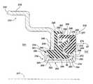
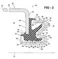
- FIG. 2is an enlarged cross-sectional view of the non-contact labyrinth seal assembly of FIG. 1 ;
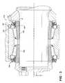
- FIG. 3is a partial cross-sectional view of a shaft and roller bearing assembly with a non-contact labyrinth seal assembly constructed in accordance with another presently preferred embodiment of the invention
- FIG. 4is a cross-sectional view of a bearing assembly with a non-contact labyrinth seal assembly constructed in accordance with yet another presently preferred aspect of the invention
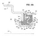
- FIG. 4Ais an enlarged cross-sectional view of the non-contact labyrinth seal assembly of FIG. 4 ;
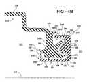
- FIG. 4Bis an enlarged cross-sectional view of a non-contact labyrinth seal assembly constructed in accordance with yet another presently preferred aspect of the invention.
- FIG. 4Cis an enlarged cross-sectional view of a non-contact labyrinth seal assembly constructed in accordance with yet another presently preferred aspect of the invention.
- FIG. 1illustrates a self-contained, pre-lubricated and preset bearing assembly 10 disposed about a journal 12 of a shaft or axle 14 and within a housing 16 to provide relative rotation between the axle 14 and housing 16 about a central axis 17 of the shaft 14 and assembly 10 .
- the bearing assembly 10has a single outer race 18 received in the housing and a pair of inner races 20 separated by a spacer 21 and being clamped between a backing ring 22 and an end cap 24 , with a plurality of rollers 26 maintained between the inner races 20 and the outer race 18 .
- the bearing assembly 10has a pair of purely non-contact labyrinth seal assemblies 30 , illustrated in FIGS. 1 and 2 in accordance with one aspect of the invention, on opposite sides of the bearing assembly 10 to maintain the lubrication on an oil side 31 of the seal assemblies 30 and within bearing assembly 10 and to prevent the ingress of contamination from an air side 33 of the seal assemblies 30 , such as dirt and debris, into the bearing assembly 10 .
- the seal assemblies 30having a completely non-contact labyrinth construction, as discussed in more detail hereafter, produce minimal friction in use, while effectively preventing the egress of lubrication and ingress of contamination, thus, enhancing the performance and prolonging the useful life of the bearing assembly 10 .
- each non-contact labyrinth seal assembly 30has an outer rigid carrier 32 , preferably constructed from metal, such as from steel in a stamping operation, with an elastomeric seal body 34 attached thereto, and a metal inner sleeve 36 .
- the carrier 32has a generally cylindrical outer flange 38 extending axially relative to the central axis 17 of the assembly 30 with an annular leg 40 extending radially inwardly from the outer flange 38 toward the central axis 17 .
- the outer flange 38extends axially to a free end 42 that is preferably configured for direct attachment to the outer race 18 of the bearing assembly 10 , though it could be configured for attachment to the housing 16 , or otherwise.
- the leg 40has opposite oil and air sides 44 , 45 corresponding to and facing the oil and air sides 31 , 33 of the bearing assembly 10 , respectively, that extend to a free end 46 .
- One or both of the sides 44 , 45can be treated, if desired, to facilitate bonding of the seal body 34 thereto, such as in an etching or sand/bead blasting operation, for example.
- the elastomeric seal body 34is attached to the leg 40 , such as by using a suitable adhesive or by molding directly to the leg 40 .
- the body 34is shown here, by way of example and without limitation, as being molded about the free end 46 of the leg 40 in bonded relation to the leg 40 and substantially covering the air side 45 of the leg 40 .
- the body 34has a radially outward lip 48 and radially inward lip 50 .
- the lips 48 , 50extend laterally from the leg 40 toward the air side 33 of the assembly 30 .
- the radially outward lip 48diverges from the inward lip 50 and outwardly from the central axis 17 to provide a first annular channel 54 between the lips 48 , 50 and a second annular gutter, referred to hereafter as channel 56 , between the radially outward lip 48 and the leg 40 of the carrier 32 .
- the first annular channel 54faces axially toward the air side 33 of the assembly 30 and the second annular channel 56 faces radially outwardly from the central axis 17 , and acts to inhibit the ingress of contamination into the bearing assembly 10 .
- the bodyalso has an undulating surface 58 facing radially inwardly toward the central axis 17 .
- the undulating surface 58extends axially along an inner bottom surface of the body 34 , and is shown here as being provided partially by the inward lip 50 .
- the lip 50has a radially inwardly facing surface 51 that diverges away from the axis 17 toward the air side 33 of the assembly 30 , such that during relative movement between the carrier 32 and the inner sleeve 36 , the surface 51 acts to repell the ingress of contamination into the bearing assemlby 10 .
- the undulating surface 50also has a plurality of radially inwardly facing surfaces 53 axially inwardly from the surface 51 .
- the surfaces 53diverge away from the axis 17 toward the oil side 31 of the assembly 30 , such that during relative movement between the carrier 32 and the inner sleeve 36 , the surfaces 53 act to repell the egress of lubrication from the bearing assemlby 10 .
- the body 34further includes an exclusion lip 60 extending axially from the leg 40 toward the air side 33 of the assembly 30 .
- the exclusion lip 60is located radially outwardly from and in partially overlapping relation to the second annular channel 56 .
- the body 34further includes a containment lip 61 extending axially toward the oil side 31 of the assembly 30 .
- the containment lip 61is shown here, by way of example and without limitation, as extending generally from the free end 46 of the leg 40 axially toward the oil side 31 of the assembly 30 .
- the metal inner sleeve 36is preferably constructed from steel in a stamping operation, though other metal materials and processes could be used.
- the inner sleeve 36has an axially extending cylindrical wall 62 with an inner surface 64 configured for operable disposal about the shaft 14 , and shown in FIGS. 1 and 2 , by way of example and without limtation, as being received on the spacer rings 28 .
- the inner sleeve 36also has an outer surface 65 opposite the inner surface 64 .
- the sleeve 36has an annular wall, also referred to as flange, or lip 66 extending radially outwardly from the wall 62 to an exclusion flange 68 .
- the exclusion flange 68extends axially from the barrier 66 in a radially outwardly overlapping relation with the cylindrical wall 62 to a free end 69 , wherein the wall 62 and the exclusion flange 68 are shown here as being substantially parallel to one another.
- the barrier 66has an annular projection 70 extending axially between the cylindrical wall 62 and the exclusion flange 68 , and is shown here as being upset in the material of the the sleeve 36 , such that the projection 70 is plastically deformed in the barrier 66 .
- the projection 70is generally ⁇ -shaped, as shown in FIG.
- the projection 70has an annular upper leg 76 diverging radially outwardly from the lower leg 72 toward the air side 33 , wherein the upper leg 76 acts as a slinger to repell contamination radially ouwardly from the seal assembly 30 .
- the upper leg 76transitions to the exclusion flange 68 at a reverse folded portion 77 . Accordingly, another annular pocket 78 is formed between the upper leg 76 and the exclusion flange 68 , wherein the pocket 78 is radially outwardly aligned with the radially inward pocket 74 .
- the sleeve 36has a containment flange 80 extending radially outwardly from the cylindrical wall 62 .
- the containment flange 80in addition to maintaining the assembly 30 in an assembled state, assists in preventing lubrication within the bearing assembly 10 from escaping the oil side 31 , while also acting to prevent the ingress of any contamination into the oil side 31 .
- the bearing assembly 10With the carrier 32 assembled to the outer race 18 and the sleeve 36 disposed about the axle 14 , the bearing assembly 10 is maintained in a preset condition with the seal assembly 30 being maintained in a purely non-contact labyrinth seal configuration. Accordingly, the seal body 34 and its associated features remain in spaced relation from the sleeve 36 .
- the annular projection 70 of the sleeve 36extends axially into the first annular channel 54 to provide a non-contact labyrinth passage 82 that extends along a serpentine path between the respective radially outward and radially inward lips 48 , 50 and the annular projection 70 .
- the radially inward lip 50extends into the pocket 74 in non-contacting relation with the sleeve 36 to provide a non-contact labyrinth passage 83 extending in open communication from the labyrinth passage 82 , wherein the labyrinth passage 83 extends over a generally U-shaped or serpentine path within the pocket 74 .
- the undulating surface 58 of the seal body 34extends axially in spaced relation from the outer surface 65 of the sleeve wall 62 to provide a non-contact labyrinth passage 84 extending axially in open communication from the labyrinth passage 83 .
- the exclusion flange 68 of the sleeve 36extends in radially outward overlapping relation with the second annular channel 56 , wherein the exclusion flange 68 is spaced radially outwardly from the radially outward lip 48 .
- the exclusion lip 60 of the seal body 34extends in spaced, overlapping relation with the free end 69 of the exclusion flange 68 , with the exclusion lip 60 being shown as being spaced radially outwardly from the exclusion flange 68 to provide a gap, wherein the gap provides a generally horizontally extending, non-contact labyrinth passage 81 configured in open communication with the second annular channel 56 .
- the gutter or channel 56is able to contain contamination on the radially upward half section of the seal assembly 30 and drain or dispell the contamination through the labyrinth passage 81 on the radially downward half of the seal assembly 30 with the assistance of gravitational and centripal forces.
- the containment flange 80extends radially outwardly from the cylindrical wall 62 radially beyond at least a portion of the elastomeric body 34 , shown here as extending radially beyond the undulating surface 58 , while remaining axially spaced from the undulating surface 58 to maintain a non-contact labyrinth passage 85 extending from the labyrinth passage 84 .
- the containment lip 61extends axially toward the oil side 31 in radially outwardly overlapping relation with the containment flange 80 .
- the containment lip 61is spaced radially outwardly from the containment flange 80 to extend the non-contacting labyrinth passage 85 in open communication with the oil side 31 of the assembly 30 .
- seal assembly 30is configured to maintain an entirely non-contact construction, with the continuously extending labyrinth passages 81 , 82 , 83 , 84 , 85 providing minimal friction in use, while preventing the ingress of contamination and the egress of lubrication.
- the labyrinth passages 82 , 83 , 84 , and 85are provided having a generally or substantially constant width (W), such as between about 0.010-0.100′′, extending along the radially outward lip 48 , the radially inward lip 50 and the undulating surface 58 . It should be recognized that some variations in the width W along the labyrinth passages 82 , 83 , 84 , 85 is contemplated, such as would inherently occur along the undulating surface 58 , for example.
- a self-contained, pre-lubricated and preset bearing assembly 110is shown in accordance with another presently preferred construction, wherein the same reference numerals as used above, offset by a factor of 100 , are used to identify similar features.
- the bearing assembly 110is constructed generally same as the previously discussed bearing assembly 10 , with a labyrinth seal assembly 130 operably coupled to the bearing assembly 110 , thereby providing a completely non-contact labyrinth seal construction, however, rather than an inner sleeve 136 of the seal assembly 130 being mounted on a spacer ring, the inner sleeve 136 is configured to be mounted directly on an outer surface of a thrust rib 21 of an inner race 120 .
- the configuration of a carrier 132 of the seal assembly 130is altered to accommodate the change in configuration of the inner sleeve 136 .
- the carrier 132is generally L-shaped in cross-section, with a leg 140 of the carrier 132 depending directly radially inwardly from a cylindrical outer flange 138 of the assembly 110 .
- the seal assembly 130is the same as the previously discussed seal assembly 30 , and thus, no further discussion is believed necessary.
- FIG. 4a self-contained, pre-lubricated and preset bearing assembly 210 with a non-contact labyrinth seal assembly 230 constructed in accordance with another presently preferred embodiment is shown, wherein the same reference numerals as used above, offset by a factor of 200 , are used to identify similar features. As best shown in FIG. 4
- the seal assembly 230has an outer rigid carrier 232 , preferably constructed from metal, such as from steel in a stamping operation, a seal body 234 attached to the carrier 232 , a metal inner sleeve 236 , and an elastomeric seal body, referred to hereafter as elastomeric body or simply body 87 , attached to the inner sleeve 236 to provide a unitary inner sleeve subassembly.
- the carrier 232has a generally cylindrical outer flange 238 extending axially relative to a central axis 217 of the assembly 230 with a leg 240 extending radially inwardly from the outer flange 238 toward the central axis 217 .
- the outer flange 238extends axially to a free end 242 that is preferably configured for direct attachment an outer race of a bearing assembly, though it could be configured for attachment to other than the bearing assembly.
- the leg 240has opposite oil and air sides 244 , 245 facing an oil side 231 and air side 233 , respectively, wherein the leg 240 extends to a free end 246 .
- the elastomeric seal body 234is attached to the free end 246 of the leg 240 , and is configured generally the same as described above with regard to the seal body 34 . Accordingly, the seal body has a pair of lips 248 , 250 , with the radially outward lip 248 diverging from the radially inward lip 250 and outwardly from the central axis 217 to provide a first annular channel 254 between the lips 248 , 250 and a second annular channel 256 between the radially outward lip 248 and the leg 240 of the carrier 232 .
- the bodyalso has an undulating surface 258 facing radially inwardly toward the central axis 217 and extending axially along an inner bottom surface of the body 234 , and being provided in part by the inward lip 250 .
- the body 234further includes an exclusion lip 260 extending axially from the leg 240 toward the air side 233 of the assembly 230 .
- the exclusion lip 260is located radially outwardly from and in partially overlapping relation to the second annular channel 256 .
- the body 234further includes a containment lip 261 extending axially toward the oil side 231 of the assembly 230 .
- the containment lip 261is shown here, by way of example and without limitation, as extending generally from the free end 246 of the leg 240 in radially outward relation to the undulating surface 258 .
- the metal inner sleeve 236 and the elastomeric body 87are configured having a generally similar cross-sectional shape as the inner sleeve 36 discussed above. Accordingly, the inner sleeve 236 and the elastomeric body 87 subassembly cooperate with the outer metal carrier 232 and seal body 234 to provide a non-contact labyrinth seal assembly similarly as discussed above with regard to the seal assembly 30 . However, the elastomeric body 87 negates the need for many of the progressive manufacturing processes used to form the aforementioned upset annular projection 70 and exclusion flange 68 of the carrier 32 .
- the inner sleeve 236is preferably constructed from steel, such as in a stamping operation, although other manufacturing processes are contemplated.
- the inner sleeve 236has an axially extending cylindrical wall 262 with an inner surface 264 and an outer surface 265 , with the inner surface 264 being configured for operable disposal about a shaft, inner race of a bearing, or, as illustrated, by way of example and without limitation, a spacer ring 228 ( FIG. 4 ).
- the sleeve 236is generally U-shaped in axial cross-section, having an annular wall, also referred to as flange, barrier, projection or lip 266 extending radially outwardly from the cylindrical wall 262 .
- the sleeve 236has a containment flange 280 extending radially outwardly from the cylindrical wall 262 .
- the containment flange 280functions similarly as discussed above with regard to the containment flange 80 .
- the elastomeric body 87is preferably molded to the lip 266 of the inner sleeve 236 , with the body 87 being formed from an elastomeric or polymeric material, although it could be otherwise attached, such as via an adhesive, for example.
- the elastomeric body 87forms an exclusion flange 268 extending axially from the metal lip 266 in a radially outwardly overlapping relation with the cylindrical wall 262 to a free end 269 , wherein the wall 262 and the exclusion flange 268 are shown here as being substantially parallel to one another.
- the body 87has an annular projection 270 extending axially inwardly from the lip 266 between the cylindrical wall 262 and the exclusion flange 268 .
- the projection 270is generally nose shaped, having generally the same inside conour as that of the projection 70 discussed above. As such, the projection has an annular lower, radially inward inner surface 272 spaced radially outward in overlapping relation with the cylindrical wall 262 to provide an annular pocket 274 between the projection 270 and the cylindrical wall 262 .
- the projection 270has an annular upper, radially outward inner surface 276 diverging radially outwardly from the lower inner surface 272 toward the air side 233 , wherein the upper inner surface 276 transitions to the exclusion flange 268 at a reverse molded portion 277 . Accordingly, another annular pocket 278 is formed between the upper inner surface 276 and the exclusion flange 268 , wherein the pocket 278 is radially outwardly aligned with the radially inward pocket 274 .
- the bearing assembly 210is maintained in a preset condition with the seal assembly 230 being maintained in a purely non-contact labyrinth seal configuration. Accordingly, the seal body 234 and its associated features remain in spaced relation from the sleeve 236 and the elastomeric body 87 .
- the annular projection 270 of the elastomeric body 87extends axially into the first annular channel 254 to provide a non-contact labyrinth passage 282 that extends along a serpentine path between the respective radially outward and radially inward lips 248 , 250 and the annular projection 270 .
- the radially inward lip 250extends into the pocket 274 in non-contacting relation with the sleeve 236 and the elastomeric body 87 to provide a non-contact labyrinth passage 283 extending in open communication from the labyrinth passage 282 , wherein the labyrinth passage 283 extends over a generally U-shaped or serpentine path within the pocket 274 .
- the undulating surface 258 of the seal body 234extends axially in spaced relation from the outer surface 265 of the sleeve wall 262 to provide a non-contact labyrinth passage 284 extending axially in open communication from the labyrinth passage 283 .
- the exclusion flange 268 of the elastomeric body 87extends in radially outward overlapping relation with the second annular channel 256 , wherein the exclusion flange 268 is spaced radially outwardly from the radially outward lip 248 .
- the exclusion lip 260 of the seal body 234extends in spaced, overlapping relation with the free end 269 of the exclusion flange 268 , with the exclusion lip 260 being shown as being spaced radially outwardly from the exclusion flange 268 to provide a gap, wherein the gap provides a generally horizontally extending, non-contact labyrinth passage 281 configured in open communication with the second annular channel 256 .
- the containment flange 280extends radially outwardly from the cylindrical wall 262 radially beyond at least a portion of the elastomeric seal body 234 , shown here as extending radially beyond the undulating surface 258 , while remaining axially spaced from the undulating surface 258 to maintain a non-contact labyrinth passage 285 extending from the labyrinth passage 284 .
- the containment lip 261extends axially toward the oil side 231 in radially outwardly overlapping relation with the containment flange 280 .
- seal assembly 230is configured to maintain an entirely non-contact construction, with the continuously extending labyrinth passages 281 , 282 , 283 , 284 , 285 providing minimal friction in use, while preventing the ingress of contamination and the egress of lubrication.
- the labyrinth passages 282 , 283 , 284 , and 285are provided having a generally or substantially constant width (W) extending along the radially outward lip 248 , the radially inward lip 250 and the undulating surface 258 . It should be recognized that some variations in the width W along the labyrinth passages 282 , 283 , 284 , 285 is contemplated, such as would inherently occur along the undulating surface 58 , for example.
- a non-contact labyrinth seal assembly 330constructed in accordance with another presently preferred embodiment is shown, wherein the same reference numerals as used above, offset by a factor of 300 , are used to identify similar features.
- the seal assembly 330is configured having generally the same shape in axial cross-section as the previous assemblies 30 , 130 , 230 , and includes an outer rigid carrier 332 , a seal body 334 attached to the carrier 332 , and an inner sleeve 336 .
- the carrier 332 and the seal body 334are constructed in accordance with another method of constructing the assembly by forming the carrier 332 and the seal body 334 as a single piece of material, such as in a molding process, for example
- the carrier 332 and the seal body 334are molded from a sufficiently rigid polymeric material to allow it to be attached or received in a housing, such as in an outer ring of a railway bearing assembly, for example.
- the inner sleeve 336is molded from a sufficiently rigid polymeric material to allow it to be received about a shaft.
- the carrier 332has a generally cylindrical outer flange 338 extending axially relative to a central axis 317 with a leg 340 extending radially inwardly from the outer flange 338 .
- the leg 340has opposite oil and air sides 344 , 345 facing an oil side 331 and air side 333 .
- the seal body 334has a pair of lips 348 , 350 diverging from one another as described above to provide a first annular channel 354 between the lips 348 , 350 and a second annular channel 356 between the radially outward lip 348 and the leg 340 . Further, the body has an undulating surface 358 facing radially inwardly toward the central axis 317 , and further includes an exclusion lip 360 and a containment lip 361 as described above with regard to the previous embodiments.
- the inner sleeve 336has an axially extending cylindrical wall 362 with an inner surface 364 and an outer surface 365 , with the inner surface 364 being configured for operable disposal about a shaft, inner race of a bearing, or a spacer ring.
- the sleeve 336has a containment flange 380 extending radially outwardly from the cylindrical wall 362 , wherein the containment flange 380 functions similarly as discussed above.
- the sleeve 336further includes an exclusion flange 368 and an annular projection 370 extending axially inwardly between the cylindrical wall 362 and the exclusion flange 368 .
- the projection 370is generally nose shaped, having generally the same inside conour as that of the projection 270 discussed above. As such, the projection 370 has an annular lower, radially inward inner surface 372 spaced radially outward in overlapping relation with the cylindrical wall 362 to provide an annular pocket 374 between the projection 370 and the cylindrical wall 362 .
- the projection 370has an annular upper, radially outward inner surface 376 diverging radially outwardly from the lower inner surface 372 toward the air side 333 , wherein the upper inner surface 376 transitions to the exclusion flange 368 at a reverse molded portion 377 . Accordingly, another annular pocket 378 is formed between the upper inner surface 376 and the exclusion flange 368 .
- the annular projection 370When assembled, the annular projection 370 extends axially into the first annular channel 354 to provide a non-contact labyrinth passage 382 that extends along a serpentine path between the respective radially outward and radially inward lips 348 , 350 and the annular projection 370 . Further, the radially inward lip 350 extends into the pocket 374 in non-contacting relation to provide a non-contact labyrinth passage 383 extending in open communication from the labyrinth passage 382 , wherein the labyrinth passage 383 extends over a generally U-shaped or serpentine path within the pocket 374 .
- the undulating surface 358extends axially in spaced relation from the outer surface 365 of the sleeve wall 362 to provide a non-contact labyrinth passage 384 extending axially in open communication from the labyrinth passage 383 .
- the exclusion flange 368extends in radially outward, spaced overlapping relation with the second annular channel 356 and the exclusion lip 360 extends in spaced, overlapping relation with the exclusion flange 368 to provide a gap, wherein the gap provides a generally horizontally extending, non-contact labyrinth passage 381 configured in open communication with the second annular channel 356 .
- the containment flange 380extends radially outwardly from the cylindrical wall 362 beyond the undulating surface 358 , while remaining axially spaced from the undulating surface 358 to maintain a non-contact labyrinth passage 385 extending in open communication from the labyrinth passage 384 .
- FIG. 4Ca non-contact labyrinth seal assembly 430 constructed in accordance with another presently preferred embodiment is shown, wherein the same reference numerals as used above, offset by a factor of 400 , are used to identify similar features.
- the seal assembly 430is configured having generally the same shape in axial cross-section taken along an axis 417 as the previous assemblies 30 , 130 , 230 , 330 and includes an outer rigid carrier 432 , a seal body 434 attached to the carrier 432 , an inner sleeve 436 , and a polymeric body 487 attached to the inner sleeve 436 .
- the seal assembly 430is molded of polymeric materials, however, rather than the carrier 432 and the seal body 434 being constructed of the same material, they are constructed in accordance with another method of constructing the assembly by molding the carrier 432 and the seal body 434 as separate pieces attached to one another, and thus, can be molded using different types of polymeric materials.
- the carrier 432can be formed by molding it using one rigid polymeric material
- the seal body 434can be formed by molding it using a second, elastic polymeric material, such as rubber, for example.
- the inner sleeve 436can be molded from a sufficiently rigid polymeric material to allow it to be received about a shaft
- the polymeric body 487can be molded from a second, elastic polymeric material, such as rubber, for example.
- labyrinth passages 482 , 483 , 484 , and 485are provided having a generally or substantially constant width (W) extending along a radially outward lip 448 , a radially inward lip 450 and an undulating surface 458 .
- a non-contact labyrinth passage 481is configured in open communication with an annular channel 456 , which in turn, is in open communication with the labyrinth passage 482 .
- a lubricantsuch as a grease 89 of suitable weight can be provided in the labyrinth passage 484 between the undulating surface 458 and the inner sleeve 436 to further inhibit the ingress of contamination and the egress of lubricant.
Landscapes
- Engineering & Computer Science (AREA)
- General Engineering & Computer Science (AREA)
- Mechanical Engineering (AREA)
- Sealing Using Fluids, Sealing Without Contact, And Removal Of Oil (AREA)
- Sealing Of Bearings (AREA)
Abstract
Description
Claims (18)
Priority Applications (2)
| Application Number | Priority Date | Filing Date | Title |
|---|---|---|---|
| US13/708,294US8991829B2 (en) | 2007-11-20 | 2012-12-07 | Non-contact labyrinth seal assembly and method of construction thereof |
| US14/622,809US9291272B2 (en) | 2007-11-20 | 2015-02-13 | Non-contact labyrinth seal assembly and method of construction thereof |
Applications Claiming Priority (3)
| Application Number | Priority Date | Filing Date | Title |
|---|---|---|---|
| US98919007P | 2007-11-20 | 2007-11-20 | |
| US12/273,995US8342535B2 (en) | 2007-11-20 | 2008-11-19 | Non-contact labyrinth seal assembly and method of construction thereof |
| US13/708,294US8991829B2 (en) | 2007-11-20 | 2012-12-07 | Non-contact labyrinth seal assembly and method of construction thereof |
Related Parent Applications (1)
| Application Number | Title | Priority Date | Filing Date |
|---|---|---|---|
| US12/273,995DivisionUS8342535B2 (en) | 2007-11-20 | 2008-11-19 | Non-contact labyrinth seal assembly and method of construction thereof |
Related Child Applications (1)
| Application Number | Title | Priority Date | Filing Date |
|---|---|---|---|
| US14/622,809ContinuationUS9291272B2 (en) | 2007-11-20 | 2015-02-13 | Non-contact labyrinth seal assembly and method of construction thereof |
Publications (2)
| Publication Number | Publication Date |
|---|---|
| US20140159318A1 US20140159318A1 (en) | 2014-06-12 |
| US8991829B2true US8991829B2 (en) | 2015-03-31 |
Family
ID=50880105
Family Applications (2)
| Application Number | Title | Priority Date | Filing Date |
|---|---|---|---|
| US13/708,294ActiveUS8991829B2 (en) | 2007-11-20 | 2012-12-07 | Non-contact labyrinth seal assembly and method of construction thereof |
| US14/622,809Active2028-11-27US9291272B2 (en) | 2007-11-20 | 2015-02-13 | Non-contact labyrinth seal assembly and method of construction thereof |
Family Applications After (1)
| Application Number | Title | Priority Date | Filing Date |
|---|---|---|---|
| US14/622,809Active2028-11-27US9291272B2 (en) | 2007-11-20 | 2015-02-13 | Non-contact labyrinth seal assembly and method of construction thereof |
Country Status (1)
| Country | Link |
|---|---|
| US (2) | US8991829B2 (en) |
Cited By (6)
| Publication number | Priority date | Publication date | Assignee | Title |
|---|---|---|---|---|
| US20180156336A1 (en)* | 2015-09-01 | 2018-06-07 | Nok Corporation | Sealing apparatus |
| US20200025244A1 (en)* | 2018-07-17 | 2020-01-23 | Jtekt Corporation | Rolling bearing device |
| US10900524B2 (en) | 2017-09-15 | 2021-01-26 | Ntn Corporation | Sealing member, and bearing device for vehicle wheel comprising same |
| US11813729B2 (en) | 2018-05-14 | 2023-11-14 | Black & Decker Inc. | Power tool with partition assembly between transmission and motor |
| US11817757B2 (en) | 2018-05-14 | 2023-11-14 | Black & Decker Inc. | Power tool with partition assembly between transmission and motor |
| US12107475B2 (en)* | 2022-05-06 | 2024-10-01 | Ford Global Technologies, Llc | Vehicle and electric machine configuration for a vehicle |
Families Citing this family (14)
| Publication number | Priority date | Publication date | Assignee | Title |
|---|---|---|---|---|
| JP5926382B2 (en)* | 2012-07-30 | 2016-05-25 | Nok株式会社 | Sealing device |
| JP6224576B2 (en)* | 2014-12-24 | 2017-11-01 | アイシン精機株式会社 | Rotating shaft seal structure of vehicle drive device |
| US10190637B2 (en)* | 2015-03-09 | 2019-01-29 | Ntn Corporation | Sealed bearing assembly |
| US10363444B2 (en)* | 2015-09-30 | 2019-07-30 | Specified Technologies Inc. | Self-adjusting firestopping sleeve apparatus |
| KR102656377B1 (en)* | 2015-12-11 | 2024-04-12 | 가부시키가이샤 시마노 | Line roller and spinning reel using the line roller |
| JP6700778B2 (en)* | 2015-12-25 | 2020-05-27 | 株式会社シマノ | Line roller |
| CN105711444B (en)* | 2016-03-30 | 2018-05-11 | 中车青岛四方机车车辆股份有限公司 | A kind of snakelike unsteady repression system and method for rail vehicle |
| DE102016212127A1 (en)* | 2016-07-04 | 2018-01-04 | Schaeffler Technologies AG & Co. KG | Sealing arrangement with sealing ring and machine element arrangement |
| JP6789739B2 (en)* | 2016-09-08 | 2020-11-25 | Ntn株式会社 | Bearing with seal |
| WO2018097737A1 (en)* | 2016-11-28 | 2018-05-31 | Granberg AS | Three-dimensional, 3d, knitted fabric, and method of manufacturing same |
| CN208252774U (en)* | 2018-03-23 | 2018-12-18 | 深圳市创世纪机械有限公司 | Air tight means for main shaft |
| DE102019204878A1 (en)* | 2018-04-06 | 2019-10-10 | Nabtesco Corporation | Sealing structure and this seal structure having device |
| US20210040991A1 (en) | 2019-08-09 | 2021-02-11 | Amsted Rail Company, Inc. | Roller Bearing Seal Case |
| CN116726751B (en)* | 2023-06-15 | 2024-04-09 | 深圳市尚水智能股份有限公司 | Mixing device and cladding machine |
Citations (17)
| Publication number | Priority date | Publication date | Assignee | Title |
|---|---|---|---|---|
| EP0021679A1 (en) | 1979-06-27 | 1981-01-07 | Uchiyama Manufacturing corp. | Rolling bearing |
| JPH0225774A (en) | 1988-05-27 | 1990-01-29 | Philips Gloeilampenfab:Nv | Electronic module |
| JPH0346021A (en) | 1989-07-14 | 1991-02-27 | Nec Eng Ltd | Guidance display device |
| US5028054A (en)* | 1990-07-13 | 1991-07-02 | Fmc Corporation | Idler roller bearing and seal |
| JPH0558955A (en) | 1991-08-30 | 1993-03-09 | Nikko Kyodo Co Ltd | Method for producing β-fluoro-α-keto acid equivalent |
| JPH0558953U (en) | 1992-01-17 | 1993-08-03 | エヌティエヌ株式会社 | Sealing device for bearings for railway vehicles |
| JPH09144767A (en) | 1995-11-24 | 1997-06-03 | Koyo Seiko Co Ltd | Sealing device of bearing |
| JP2003240003A (en) | 2002-02-18 | 2003-08-27 | Nsk Ltd | Bearing seals, sealed bearings and hub unit bearings |
| US20030184021A1 (en) | 2002-03-26 | 2003-10-02 | Hatch Frederick R. | Shaft seal |
| JP2004100842A (en) | 2002-09-10 | 2004-04-02 | Nsk Ltd | Bearing seal |
| US6845986B2 (en)* | 2002-04-26 | 2005-01-25 | Stemco Llc | Low torque seal assembly |
| JP2005076723A (en) | 2003-08-29 | 2005-03-24 | Ntn Corp | Railway axle-box bearing |
| KR20060134016A (en) | 2003-12-16 | 2006-12-27 | 쉐플러 카게 | Seals with deflection rings arranged in contact with each other |
| JP2007009938A (en) | 2005-06-28 | 2007-01-18 | Nok Corp | Sealing device |
| JP2007177815A (en) | 2005-12-27 | 2007-07-12 | Jtekt Corp | SEALING DEVICE AND ROLLING BEARING DEVICE USING THE SAME |
| JP2008151174A (en) | 2006-12-14 | 2008-07-03 | Uchiyama Mfg Corp | Sealing device |
| US20090127795A1 (en)* | 2007-11-20 | 2009-05-21 | Lattime Scott B | Non-contact labyrinth seal assembly and method of construction thereof |
Family Cites Families (58)
| Publication number | Priority date | Publication date | Assignee | Title |
|---|---|---|---|---|
| US1145516A (en) | 1913-06-16 | 1915-07-06 | Jakob Schmid-Roost | Dust-guard. |
| US2176294A (en) | 1938-03-26 | 1939-10-17 | Timken Roller Bearing Co | End closure for axle housings |
| US2945707A (en) | 1956-10-15 | 1960-07-19 | Wasley Products Inc | Bearing seal |
| US3021161A (en) | 1959-09-14 | 1962-02-13 | Federal Mogul Bower Bearings | Unitized shaft seal |
| US3072413A (en) | 1960-04-15 | 1963-01-08 | Gen Motors Corp | Shaft assembly |
| US3135518A (en) | 1962-04-23 | 1964-06-02 | Federal Mogul Bower Bearings | Unitized radial shaft seals |
| US3144280A (en) | 1962-06-06 | 1964-08-11 | Chain Belt Co | Seal assembly in combination with a shaft mounted roller |
| US3510138A (en) | 1965-10-15 | 1970-05-05 | Federal Mogul Corp | Oil seal with rock shield and wear sleeve |
| US3459431A (en) | 1967-03-13 | 1969-08-05 | Patrick W Baker | Oil seal-dust shield assembly |
| US3550974A (en) | 1969-05-26 | 1970-12-29 | Trw Inc | Bearing seal |
| AT319137B (en) | 1971-07-16 | 1974-12-10 | Heinz Sernetz Dipl Ing Dr Tech | Rolling bearing seal with an annular, circumferential sealing washer |
| US3822890A (en) | 1973-01-15 | 1974-07-09 | Roulements Soc Nouvelle | Bearing seals |
| US4063324A (en) | 1976-03-26 | 1977-12-20 | Kroy Industries, Inc. | Film processing apparatus |
| US4139203A (en) | 1977-04-25 | 1979-02-13 | Dresser Industries, Inc. | Labyrinth type rotary seal with intermittent feature of contact type seal |
| DE3066788D1 (en) | 1979-03-09 | 1984-04-12 | Skf Uk Ltd | Bearing assemblies for conveyor rollers fitted with end covers |
| US4327922A (en) | 1979-11-23 | 1982-05-04 | Dayton-Walther Corporation | Reusable seals with double shell mountings |
| DE3204989C2 (en) | 1982-02-12 | 1983-12-15 | Fa. Carl Freudenberg, 6940 Weinheim | Cassette seal |
| US4477693A (en) | 1982-12-09 | 1984-10-16 | Cooper Industries, Inc. | Multiply shielded coaxial cable with very low transfer impedance |
| DE3300942C1 (en) | 1983-01-13 | 1984-05-24 | Goetze Ag, 5093 Burscheid | Shaft seal |
| US4460803A (en) | 1983-02-15 | 1984-07-17 | Woven Electronics Corporation | Unitary woven jacket and electrical transmission cable and method of making same |
| US5004248A (en) | 1983-08-25 | 1991-04-02 | Garlock Inc. | Unitized seal with unitizing joint remote from seal lip |
| DE3503732A1 (en) | 1985-02-04 | 1986-08-07 | Siemens AG, 1000 Berlin und 8000 München | FLAME RETARDED PLASTIC CABLE SLEEVE |
| NL8501411A (en) | 1985-05-15 | 1986-12-01 | Skf Ind Trading & Dev | SEAL FOR A BEARING. |
| US4699526A (en) | 1985-08-01 | 1987-10-13 | Nok Corporation | Sealing device for bearings |
| US4770424A (en) | 1985-12-19 | 1988-09-13 | The Timken Company | Compact labyrinth-type seal |
| US4819949A (en) | 1985-12-19 | 1989-04-11 | Timken Company | Shielded seal assembly |
| US4906111A (en) | 1986-10-06 | 1990-03-06 | Martinie Howard W | Auxiliary sealing system |
| JP2526587B2 (en) | 1987-07-07 | 1996-08-21 | トヨタ自動車株式会社 | Air-fuel ratio control device for internal combustion engine |
| IT1206866B (en) | 1987-01-28 | 1989-05-11 | Riv Officine Di Villar Perosa | WATERPROOF BEARING FOR EXCEPTIONALLY SERIOUS WORKING CONDITIONS |
| US4852890A (en) | 1988-02-03 | 1989-08-01 | Garlock Inc. | Rotary shaft bearing isolator seal |
| JPH0722532Y2 (en) | 1988-06-14 | 1995-05-24 | エヌオーケー株式会社 | Sealing device |
| US4981303A (en) | 1988-10-25 | 1991-01-01 | Nok Corporation | Sealing device |
| SE461803B (en) | 1989-03-17 | 1990-03-26 | Skf Mekanprodukter Ab | DEVICE FOR THE ASSEMBLY OF A BEARING ON AN AXLE |
| JP2804517B2 (en) | 1989-06-15 | 1998-09-30 | エヌオーケー株式会社 | Sleeve with slinger for oil seal and seal assembly thereof |
| JPH0344767A (en) | 1989-07-13 | 1991-02-26 | Hitachi Maxell Ltd | image file device |
| US5201529A (en) | 1990-02-16 | 1993-04-13 | Nok Corporation | Sealing device |
| IT1252112B (en) | 1990-07-25 | 1995-06-05 | Zahnradfabrik Friedrichshafen | ARRANGEMENT OF BOX CONSTRUCTION TYPE |
| US5183269A (en) | 1991-02-06 | 1993-02-02 | Chicago Rawhide Manufacturing Co. | Unitized grit seal with removable thrust bumper |
| WO1992015189A1 (en) | 1991-02-20 | 1992-09-03 | Instrument Specialties Company, Inc. | Heat-treated wire-mesh emi/rfi shielding gasket |
| JPH0558953A (en) | 1991-09-04 | 1993-03-09 | Idemitsu Kosan Co Ltd | Production of 2-hydroxyisobutyric acid ester |
| US5269536A (en) | 1991-04-15 | 1993-12-14 | Nok Corporation | Sealing device |
| US5129744A (en) | 1991-06-17 | 1992-07-14 | The Timken Company | Two component bearing seal with bumpers |
| JPH0566921A (en) | 1991-09-10 | 1993-03-19 | Fujitsu Ltd | Data shift circuit |
| US5387113A (en) | 1992-09-24 | 1995-02-07 | Woven Electronics Corp. | Composite shield jacket for electrical transmission cable |
| US5617900A (en) | 1993-07-20 | 1997-04-08 | Davlyn Manufacturing Co., Inc. | Multilayer flexibility resilient thermal shielding sleeves |
| DE4327988A1 (en) | 1993-08-20 | 1995-02-23 | Precismeca Gmbh | Conveyor belt roll |
| IT1280443B1 (en) | 1995-07-21 | 1998-01-20 | Skf Ind Spa | SEALING DEVICE FOR BEARINGS |
| DE19624611A1 (en) | 1996-06-20 | 1998-01-02 | Freudenberg Carl Fa | Device for sealing an annular gap between a housing and a shaft |
| US5965223A (en) | 1996-10-11 | 1999-10-12 | World Fibers, Inc. | Layered composite high performance fabric |
| US6050570A (en) | 1998-01-30 | 2000-04-18 | The Timken Company | Seal with bi-modulus lip |
| US6213476B1 (en) | 1998-09-03 | 2001-04-10 | Federal-Mogul World Wide, Inc. | Bi-modulus composite seal and its method of manufacture |
| US6262371B1 (en) | 1999-06-23 | 2001-07-17 | Marc Talon, Inc. | Method and apparatus for dividing a conduit into compartments |
| EP1212556A1 (en) | 1999-08-16 | 2002-06-12 | Roller Bearing Industries, Inc. | Bearing seal |
| US6471211B1 (en) | 2000-08-28 | 2002-10-29 | Brenco, Incorporated | Seal assembly |
| JP2003148497A (en) | 2001-11-13 | 2003-05-21 | Nsk Ltd | Sealed rolling bearing |
| US6718100B2 (en) | 2002-03-28 | 2004-04-06 | Milliken & Company | Fire resistant conduit insert for optical fiber cable |
| US7145083B2 (en) | 2004-07-13 | 2006-12-05 | Nortel Networks Limited | Reducing or eliminating cross-talk at device-substrate interface |
| JP5058953B2 (en) | 2007-12-06 | 2012-10-24 | 日東電工株式会社 | Manufacturing method of optical display unit and roll material used therefor |
- 2012
- 2012-12-07USUS13/708,294patent/US8991829B2/enactiveActive
- 2015
- 2015-02-13USUS14/622,809patent/US9291272B2/enactiveActive
Patent Citations (19)
| Publication number | Priority date | Publication date | Assignee | Title |
|---|---|---|---|---|
| EP0021679A1 (en) | 1979-06-27 | 1981-01-07 | Uchiyama Manufacturing corp. | Rolling bearing |
| JPS566921A (en) | 1979-06-27 | 1981-01-24 | Uchiyama Mfg Corp | Ball-and-roller bearing |
| JPH0225774A (en) | 1988-05-27 | 1990-01-29 | Philips Gloeilampenfab:Nv | Electronic module |
| JPH0346021A (en) | 1989-07-14 | 1991-02-27 | Nec Eng Ltd | Guidance display device |
| US5028054A (en)* | 1990-07-13 | 1991-07-02 | Fmc Corporation | Idler roller bearing and seal |
| JPH0558955A (en) | 1991-08-30 | 1993-03-09 | Nikko Kyodo Co Ltd | Method for producing β-fluoro-α-keto acid equivalent |
| JPH0558953U (en) | 1992-01-17 | 1993-08-03 | エヌティエヌ株式会社 | Sealing device for bearings for railway vehicles |
| JPH09144767A (en) | 1995-11-24 | 1997-06-03 | Koyo Seiko Co Ltd | Sealing device of bearing |
| JP2003240003A (en) | 2002-02-18 | 2003-08-27 | Nsk Ltd | Bearing seals, sealed bearings and hub unit bearings |
| US20030184021A1 (en) | 2002-03-26 | 2003-10-02 | Hatch Frederick R. | Shaft seal |
| US6845986B2 (en)* | 2002-04-26 | 2005-01-25 | Stemco Llc | Low torque seal assembly |
| JP2004100842A (en) | 2002-09-10 | 2004-04-02 | Nsk Ltd | Bearing seal |
| JP2005076723A (en) | 2003-08-29 | 2005-03-24 | Ntn Corp | Railway axle-box bearing |
| KR20060134016A (en) | 2003-12-16 | 2006-12-27 | 쉐플러 카게 | Seals with deflection rings arranged in contact with each other |
| JP2007009938A (en) | 2005-06-28 | 2007-01-18 | Nok Corp | Sealing device |
| JP2007177815A (en) | 2005-12-27 | 2007-07-12 | Jtekt Corp | SEALING DEVICE AND ROLLING BEARING DEVICE USING THE SAME |
| JP2008151174A (en) | 2006-12-14 | 2008-07-03 | Uchiyama Mfg Corp | Sealing device |
| US20090127795A1 (en)* | 2007-11-20 | 2009-05-21 | Lattime Scott B | Non-contact labyrinth seal assembly and method of construction thereof |
| US8342535B2 (en)* | 2007-11-20 | 2013-01-01 | The Timken Company | Non-contact labyrinth seal assembly and method of construction thereof |
Non-Patent Citations (1)
| Title |
|---|
| Extended European Search report, mailed Apr. 25, 2013 (EP08851903). |
Cited By (8)
| Publication number | Priority date | Publication date | Assignee | Title |
|---|---|---|---|---|
| US20180156336A1 (en)* | 2015-09-01 | 2018-06-07 | Nok Corporation | Sealing apparatus |
| US10605369B2 (en)* | 2015-09-01 | 2020-03-31 | Nok Corporation | Sealing apparatus |
| US10900524B2 (en) | 2017-09-15 | 2021-01-26 | Ntn Corporation | Sealing member, and bearing device for vehicle wheel comprising same |
| US11813729B2 (en) | 2018-05-14 | 2023-11-14 | Black & Decker Inc. | Power tool with partition assembly between transmission and motor |
| US11817757B2 (en) | 2018-05-14 | 2023-11-14 | Black & Decker Inc. | Power tool with partition assembly between transmission and motor |
| US20200025244A1 (en)* | 2018-07-17 | 2020-01-23 | Jtekt Corporation | Rolling bearing device |
| US10753399B2 (en)* | 2018-07-17 | 2020-08-25 | Jtekt Corporation | Rolling bearing device |
| US12107475B2 (en)* | 2022-05-06 | 2024-10-01 | Ford Global Technologies, Llc | Vehicle and electric machine configuration for a vehicle |
Also Published As
| Publication number | Publication date |
|---|---|
| US9291272B2 (en) | 2016-03-22 |
| US20140159318A1 (en) | 2014-06-12 |
| US20150159761A1 (en) | 2015-06-11 |
Similar Documents
| Publication | Publication Date | Title |
|---|---|---|
| US8342535B2 (en) | Non-contact labyrinth seal assembly and method of construction thereof | |
| US8991829B2 (en) | Non-contact labyrinth seal assembly and method of construction thereof | |
| EP0304160B1 (en) | Seal assembly | |
| CN101871487B (en) | Roller bearing | |
| EP0508013B2 (en) | Sealing elements for anti-friction bearings | |
| KR101303587B1 (en) | Sealed rolling bearing | |
| US5024449A (en) | Seal assembly for use with an overhang | |
| US20150071581A1 (en) | Preassembled insertable roller bearing unit | |
| KR102649894B1 (en) | Sealing devices for wheel bearings | |
| JP2509253B2 (en) | Bearing seal | |
| US6817769B2 (en) | Roller bearing having high performance bearing seal and cartridge | |
| CN101868639B (en) | Sealing device, rolling bearing, and rolling bearing for wheel | |
| US4664538A (en) | Sealed bearing assembly | |
| US12247629B2 (en) | Cup assembly for a universal joint bearing | |
| JP2005180575A (en) | Sealed rolling bearing | |
| EP1361372A2 (en) | Stud-type roller bearing with tracking roller | |
| JP2005069404A (en) | Sealed rolling bearing | |
| JPH01169176A (en) | Small-sized seal | |
| JP2000103335A (en) | Bearing device for railway vehicle | |
| WO2016068005A1 (en) | Rolling bearing |
Legal Events
| Date | Code | Title | Description |
|---|---|---|---|
| STCF | Information on status: patent grant | Free format text:PATENTED CASE | |
| AS | Assignment | Owner name:CITIBANK, N.A., AS COLLATERAL TRUSTEE, NEW YORK Free format text:GRANT OF SECURITY INTEREST IN UNITED STATES PATENTS;ASSIGNORS:FEDERAL-MOGUL LLC;FEDERAL-MOGUL PRODUCTS, INC.;FEDERAL-MOGUL MOTORPARTS CORPORATION;AND OTHERS;REEL/FRAME:042963/0662 Effective date:20170330 | |
| AS | Assignment | Owner name:CITIBANK, N.A., AS COLLATERAL TRUSTEE, NEW YORK Free format text:GRANT OF SECURITY INTEREST IN UNITED STATES PATENTS;ASSIGNORS:FEDERAL-MOGUL LLC;FEDERAL-MOGUL PRODUCTS, INC.;FEDERAL-MOGUL MOTORPARTS LLC;AND OTHERS;REEL/FRAME:044013/0419 Effective date:20170629 | |
| AS | Assignment | Owner name:BANK OF AMERICA, N.A., AS COLLATERAL TRUSTEE, MICHIGAN Free format text:COLLATERAL TRUSTEE RESIGNATION AND APPOINTMENT AGREEMENT;ASSIGNOR:CITIBANK, N.A., AS COLLATERAL TRUSTEE;REEL/FRAME:045822/0765 Effective date:20180223 Owner name:BANK OF AMERICA, N.A., AS COLLATERAL TRUSTEE, MICH Free format text:COLLATERAL TRUSTEE RESIGNATION AND APPOINTMENT AGREEMENT;ASSIGNOR:CITIBANK, N.A., AS COLLATERAL TRUSTEE;REEL/FRAME:045822/0765 Effective date:20180223 | |
| MAFP | Maintenance fee payment | Free format text:PAYMENT OF MAINTENANCE FEE, 4TH YEAR, LARGE ENTITY (ORIGINAL EVENT CODE: M1551); ENTITY STATUS OF PATENT OWNER: LARGE ENTITY Year of fee payment:4 | |
| AS | Assignment | Owner name:WILMINGTON TRUST, NATIONAL ASSOCIATION, AS COLLATERAL TRUSTEE, MINNESOTA Free format text:CONFIRMATORY GRANT OF SECURITY INTERESTS IN UNITED STATES PATENTS;ASSIGNORS:TENNECO INC.;TENNECO AUTOMOTIVE OPERATING COMPANY INC.;TENNECO INTERNATIONAL HOLDING CORP.;AND OTHERS;REEL/FRAME:047223/0001 Effective date:20181001 Owner name:WILMINGTON TRUST, NATIONAL ASSOCIATION, AS COLLATE Free format text:CONFIRMATORY GRANT OF SECURITY INTERESTS IN UNITED STATES PATENTS;ASSIGNORS:TENNECO INC.;TENNECO AUTOMOTIVE OPERATING COMPANY INC.;TENNECO INTERNATIONAL HOLDING CORP.;AND OTHERS;REEL/FRAME:047223/0001 Effective date:20181001 | |
| AS | Assignment | Owner name:FEDERAL-MOGUL WORLD WIDE LLC, MICHIGAN Free format text:RELEASE BY SECURED PARTY;ASSIGNOR:BANK OF AMERICA, N.A., AS COLLATERAL TRUSTEE;REEL/FRAME:047276/0771 Effective date:20181001 Owner name:FEDERAL-MOGUL PRODUCTS, INC., MICHIGAN Free format text:RELEASE BY SECURED PARTY;ASSIGNOR:BANK OF AMERICA, N.A., AS COLLATERAL TRUSTEE;REEL/FRAME:047276/0771 Effective date:20181001 Owner name:FEDERAL-MOGUL MOTORPARTS LLC, MICHIGAN Free format text:RELEASE BY SECURED PARTY;ASSIGNOR:BANK OF AMERICA, N.A., AS COLLATERAL TRUSTEE;REEL/FRAME:047276/0771 Effective date:20181001 Owner name:FEDERAL-MOGUL IGNITION COMPANY, MICHIGAN Free format text:RELEASE BY SECURED PARTY;ASSIGNOR:BANK OF AMERICA, N.A., AS COLLATERAL TRUSTEE;REEL/FRAME:047276/0771 Effective date:20181001 Owner name:FEDERAL-MOGUL LLC, MICHIGAN Free format text:RELEASE BY SECURED PARTY;ASSIGNOR:BANK OF AMERICA, N.A., AS COLLATERAL TRUSTEE;REEL/FRAME:047276/0771 Effective date:20181001 Owner name:FEDERAL MOGUL POWERTRAIN LLC, MICHIGAN Free format text:RELEASE BY SECURED PARTY;ASSIGNOR:BANK OF AMERICA, N.A., AS COLLATERAL TRUSTEE;REEL/FRAME:047276/0771 Effective date:20181001 Owner name:FEDERAL-MOGUL CHASSIS LLC, MICHIGAN Free format text:RELEASE BY SECURED PARTY;ASSIGNOR:BANK OF AMERICA, N.A., AS COLLATERAL TRUSTEE;REEL/FRAME:047276/0771 Effective date:20181001 | |
| AS | Assignment | Owner name:WILMINGTON TRUST, NATIONAL ASSOCIATION, AS CO-COLLATERAL TRUSTEE, SUCCESSOR COLLATERAL TRUSTEE, MINNESOTA Free format text:COLLATERAL TRUSTEE RESIGNATION AND APPOINTMENT, JOINDER, ASSUMPTION AND DESIGNATION AGREEMENT;ASSIGNOR:BANK OF AMERICA, N.A., AS CO-COLLATERAL TRUSTEE AND RESIGNING COLLATERAL TRUSTEE;REEL/FRAME:047630/0661 Effective date:20181001 Owner name:WILMINGTON TRUST, NATIONAL ASSOCIATION, AS CO-COLL Free format text:COLLATERAL TRUSTEE RESIGNATION AND APPOINTMENT, JOINDER, ASSUMPTION AND DESIGNATION AGREEMENT;ASSIGNOR:BANK OF AMERICA, N.A., AS CO-COLLATERAL TRUSTEE AND RESIGNING COLLATERAL TRUSTEE;REEL/FRAME:047630/0661 Effective date:20181001 | |
| AS | Assignment | Owner name:WILMINGTON TRUST, NATIONAL ASSOCIATION, MINNESOTA Free format text:SECURITY AGREEMENT;ASSIGNORS:TENNECO INC.;THE PULLMAN COMPANY;FEDERAL-MOGUL IGNITION LLC;AND OTHERS;REEL/FRAME:054555/0592 Effective date:20201130 | |
| AS | Assignment | Owner name:TENNECO INC., ILLINOIS Free format text:MERGER;ASSIGNOR:FEDERAL-MOGUL LLC;REEL/FRAME:054900/0129 Effective date:20181001 | |
| AS | Assignment | Owner name:WILMINGTON TRUST, NATIONAL ASSOCIATION, MINNESOTA Free format text:SECURITY AGREEMENT;ASSIGNORS:TENNECO INC.;TENNECO AUTOMOTIVE OPERATING COMPANY INC.;THE PULLMAN COMPANY;AND OTHERS;REEL/FRAME:055626/0065 Effective date:20210317 | |
| AS | Assignment | Owner name:DRIV AUTOMOTIVE INC., ILLINOIS Free format text:RELEASE BY SECURED PARTY;ASSIGNOR:WILMINGTON TRUST, NATIONAL ASSOCIATION;REEL/FRAME:058392/0274 Effective date:20210317 Owner name:FEDERAL-MOGUL POWERTRAIN LLC, MICHIGAN Free format text:RELEASE BY SECURED PARTY;ASSIGNOR:WILMINGTON TRUST, NATIONAL ASSOCIATION;REEL/FRAME:058392/0274 Effective date:20210317 Owner name:FEDERAL-MOGUL CHASSIS LLC, MICHIGAN Free format text:RELEASE BY SECURED PARTY;ASSIGNOR:WILMINGTON TRUST, NATIONAL ASSOCIATION;REEL/FRAME:058392/0274 Effective date:20210317 Owner name:TENNECO INC., AS SUCCESSOR TO FEDERAL-MOGUL LLC, ILLINOIS Free format text:RELEASE BY SECURED PARTY;ASSIGNOR:WILMINGTON TRUST, NATIONAL ASSOCIATION;REEL/FRAME:058392/0274 Effective date:20210317 Owner name:FEDERAL-MOGUL IGNITION, LLC, AS SUCCESSOR TO FEDERAL-MOGUL IGNITION COMPANY, MICHIGAN Free format text:RELEASE BY SECURED PARTY;ASSIGNOR:WILMINGTON TRUST, NATIONAL ASSOCIATION;REEL/FRAME:058392/0274 Effective date:20210317 Owner name:FEDERAL-MOGUL MOTORPARTS LLC, AS SUCCESSOR TO FEDERAL-MOGUL MOTORPARTS CORPORATION, MICHIGAN Free format text:RELEASE BY SECURED PARTY;ASSIGNOR:WILMINGTON TRUST, NATIONAL ASSOCIATION;REEL/FRAME:058392/0274 Effective date:20210317 Owner name:FEDERAL-MOGUL WORLD WIDE, INC., AS SUCCESSOR TO FEDERAL-MOGUL WORLD WIDE LLC, MICHIGAN Free format text:RELEASE BY SECURED PARTY;ASSIGNOR:WILMINGTON TRUST, NATIONAL ASSOCIATION;REEL/FRAME:058392/0274 Effective date:20210317 Owner name:FEDERAL-MOGUL PRODUCTS US, LLC, AS SUCCESSOR TO FEDERAL-MOGUL PRODUCTS, INC., MICHIGAN Free format text:RELEASE BY SECURED PARTY;ASSIGNOR:WILMINGTON TRUST, NATIONAL ASSOCIATION;REEL/FRAME:058392/0274 Effective date:20210317 Owner name:FEDERAL-MOGUL PRODUCTS US, LLC, AS SUCCESSOR TO FEDERAL-MOGUL PRODUCTS, INC., MICHIGAN Free format text:RELEASE BY SECURED PARTY;ASSIGNOR:WILMINGTON TRUST, NATIONAL ASSOCIATION;REEL/FRAME:056886/0455 Effective date:20210317 Owner name:FEDERAL-MOGUL WORLD WIDE, INC., AS SUCCESSOR TO FEDERAL-MOGUL WORLD WIDE LLC, MICHIGAN Free format text:RELEASE BY SECURED PARTY;ASSIGNOR:WILMINGTON TRUST, NATIONAL ASSOCIATION;REEL/FRAME:056886/0455 Effective date:20210317 Owner name:FEDERAL-MOGUL MOTORPARTS LLC, AS SUCCESSOR TO FEDERAL-MOGUL MOTORPARTS CORPORATION, MICHIGAN Free format text:RELEASE BY SECURED PARTY;ASSIGNOR:WILMINGTON TRUST, NATIONAL ASSOCIATION;REEL/FRAME:056886/0455 Effective date:20210317 Owner name:FEDERAL-MOGUL IGNITION, LLC, AS SUCCESSOR TO FEDERAL-MOGUL IGNITION COMPANY, MICHIGAN Free format text:RELEASE BY SECURED PARTY;ASSIGNOR:WILMINGTON TRUST, NATIONAL ASSOCIATION;REEL/FRAME:056886/0455 Effective date:20210317 Owner name:TENNECO INC., AS SUCCESSOR TO FEDERAL-MOGUL LLC, ILLINOIS Free format text:RELEASE BY SECURED PARTY;ASSIGNOR:WILMINGTON TRUST, NATIONAL ASSOCIATION;REEL/FRAME:056886/0455 Effective date:20210317 Owner name:FEDERAL-MOGUL CHASSIS LLC, MICHIGAN Free format text:RELEASE BY SECURED PARTY;ASSIGNOR:WILMINGTON TRUST, NATIONAL ASSOCIATION;REEL/FRAME:056886/0455 Effective date:20210317 Owner name:FEDERAL-MOGUL POWERTRAIN LLC, MICHIGAN Free format text:RELEASE BY SECURED PARTY;ASSIGNOR:WILMINGTON TRUST, NATIONAL ASSOCIATION;REEL/FRAME:056886/0455 Effective date:20210317 Owner name:DRIV AUTOMOTIVE INC., ILLINOIS Free format text:RELEASE BY SECURED PARTY;ASSIGNOR:WILMINGTON TRUST, NATIONAL ASSOCIATION;REEL/FRAME:056886/0455 Effective date:20210317 | |
| MAFP | Maintenance fee payment | Free format text:PAYMENT OF MAINTENANCE FEE, 8TH YEAR, LARGE ENTITY (ORIGINAL EVENT CODE: M1552); ENTITY STATUS OF PATENT OWNER: LARGE ENTITY Year of fee payment:8 | |
| AS | Assignment | Owner name:FEDERAL-MOGUL PRODUCTS US LLC, MICHIGAN Free format text:RELEASE BY SECURED PARTY;ASSIGNOR:WILMINGTON TRUST, NATIONAL ASSOCIATION;REEL/FRAME:061975/0218 Effective date:20221117 Owner name:FEDERAL-MOGUL FINANCING CORPORATION, MICHIGAN Free format text:RELEASE BY SECURED PARTY;ASSIGNOR:WILMINGTON TRUST, NATIONAL ASSOCIATION;REEL/FRAME:061975/0218 Effective date:20221117 Owner name:FEDERAL-MOGUL FILTRATION LLC, MICHIGAN Free format text:RELEASE BY SECURED PARTY;ASSIGNOR:WILMINGTON TRUST, NATIONAL ASSOCIATION;REEL/FRAME:061975/0218 Effective date:20221117 Owner name:BECK ARNLEY HOLDINGS LLC, MICHIGAN Free format text:RELEASE BY SECURED PARTY;ASSIGNOR:WILMINGTON TRUST, NATIONAL ASSOCIATION;REEL/FRAME:061975/0218 Effective date:20221117 Owner name:FEDERAL-MOGUL SEVIERVILLE, LLC, MICHIGAN Free format text:RELEASE BY SECURED PARTY;ASSIGNOR:WILMINGTON TRUST, NATIONAL ASSOCIATION;REEL/FRAME:061975/0218 Effective date:20221117 Owner name:FEDERAL-MOGUL VALVE TRAIN INTERNATIONAL LLC, MICHIGAN Free format text:RELEASE BY SECURED PARTY;ASSIGNOR:WILMINGTON TRUST, NATIONAL ASSOCIATION;REEL/FRAME:061975/0218 Effective date:20221117 Owner name:F-M TSC REAL ESTATE HOLDINGS LLC, MICHIGAN Free format text:RELEASE BY SECURED PARTY;ASSIGNOR:WILMINGTON TRUST, NATIONAL ASSOCIATION;REEL/FRAME:061975/0218 Effective date:20221117 Owner name:F-M MOTORPARTS TSC LLC, MICHIGAN Free format text:RELEASE BY SECURED PARTY;ASSIGNOR:WILMINGTON TRUST, NATIONAL ASSOCIATION;REEL/FRAME:061975/0218 Effective date:20221117 Owner name:FEDERAL-MOGUL CHASSIS LLC, MICHIGAN Free format text:RELEASE BY SECURED PARTY;ASSIGNOR:WILMINGTON TRUST, NATIONAL ASSOCIATION;REEL/FRAME:061975/0218 Effective date:20221117 Owner name:FEDERAL-MOGUL MOTORPARTS LLC, MICHIGAN Free format text:RELEASE BY SECURED PARTY;ASSIGNOR:WILMINGTON TRUST, NATIONAL ASSOCIATION;REEL/FRAME:061975/0218 Effective date:20221117 Owner name:FEDERAL-MOGUL IGNITION LLC, MICHIGAN Free format text:RELEASE BY SECURED PARTY;ASSIGNOR:WILMINGTON TRUST, NATIONAL ASSOCIATION;REEL/FRAME:061975/0218 Effective date:20221117 Owner name:FEDERAL-MOGUL PISTON RINGS, LLC, MICHIGAN Free format text:RELEASE BY SECURED PARTY;ASSIGNOR:WILMINGTON TRUST, NATIONAL ASSOCIATION;REEL/FRAME:061975/0218 Effective date:20221117 Owner name:FEDERAL-MOGUL POWERTRAIN IP LLC, MICHIGAN Free format text:RELEASE BY SECURED PARTY;ASSIGNOR:WILMINGTON TRUST, NATIONAL ASSOCIATION;REEL/FRAME:061975/0218 Effective date:20221117 Owner name:FEDERAL-MOGUL POWERTRAIN LLC, MICHIGAN Free format text:RELEASE BY SECURED PARTY;ASSIGNOR:WILMINGTON TRUST, NATIONAL ASSOCIATION;REEL/FRAME:061975/0218 Effective date:20221117 Owner name:MUZZY-LYON AUTO PARTS LLC, ILLINOIS Free format text:RELEASE BY SECURED PARTY;ASSIGNOR:WILMINGTON TRUST, NATIONAL ASSOCIATION;REEL/FRAME:061975/0218 Effective date:20221117 Owner name:FELT PRODUCTS MFG. CO. LLC, ILLINOIS Free format text:RELEASE BY SECURED PARTY;ASSIGNOR:WILMINGTON TRUST, NATIONAL ASSOCIATION;REEL/FRAME:061975/0218 Effective date:20221117 Owner name:FEDERAL-MOGUL WORLD WIDE LLC, MICHIGAN Free format text:RELEASE BY SECURED PARTY;ASSIGNOR:WILMINGTON TRUST, NATIONAL ASSOCIATION;REEL/FRAME:061975/0218 Effective date:20221117 Owner name:CARTER AUTOMOTIVE COMPANY LLC, ILLINOIS Free format text:RELEASE BY SECURED PARTY;ASSIGNOR:WILMINGTON TRUST, NATIONAL ASSOCIATION;REEL/FRAME:061975/0218 Effective date:20221117 Owner name:TMC TEXAS INC., ILLINOIS Free format text:RELEASE BY SECURED PARTY;ASSIGNOR:WILMINGTON TRUST, NATIONAL ASSOCIATION;REEL/FRAME:061975/0218 Effective date:20221117 Owner name:CLEVITE INDUSTRIES INC., OHIO Free format text:RELEASE BY SECURED PARTY;ASSIGNOR:WILMINGTON TRUST, NATIONAL ASSOCIATION;REEL/FRAME:061975/0218 Effective date:20221117 Owner name:TENNECO GLOBAL HOLDINGS INC., ILLINOIS Free format text:RELEASE BY SECURED PARTY;ASSIGNOR:WILMINGTON TRUST, NATIONAL ASSOCIATION;REEL/FRAME:061975/0218 Effective date:20221117 Owner name:THE PULLMAN COMPANY, OHIO Free format text:RELEASE BY SECURED PARTY;ASSIGNOR:WILMINGTON TRUST, NATIONAL ASSOCIATION;REEL/FRAME:061975/0218 Effective date:20221117 Owner name:TENNECO INTERNATIONAL HOLDING CORP., ILLINOIS Free format text:RELEASE BY SECURED PARTY;ASSIGNOR:WILMINGTON TRUST, NATIONAL ASSOCIATION;REEL/FRAME:061975/0218 Effective date:20221117 Owner name:TENNECO AUTOMOTIVE OPERATING COMPANY INC., ILLINOIS Free format text:RELEASE BY SECURED PARTY;ASSIGNOR:WILMINGTON TRUST, NATIONAL ASSOCIATION;REEL/FRAME:061975/0218 Effective date:20221117 Owner name:TENNECO INC., ILLINOIS Free format text:RELEASE BY SECURED PARTY;ASSIGNOR:WILMINGTON TRUST, NATIONAL ASSOCIATION;REEL/FRAME:061975/0218 Effective date:20221117 Owner name:DRIV AUTOMOTIVE INC., MICHIGAN Free format text:RELEASE BY SECURED PARTY;ASSIGNOR:WILMINGTON TRUST, NATIONAL ASSOCIATION;REEL/FRAME:061971/0156 Effective date:20221117 Owner name:FEDERAL-MOGUL CHASSIS LLC, MICHIGAN Free format text:RELEASE BY SECURED PARTY;ASSIGNOR:WILMINGTON TRUST, NATIONAL ASSOCIATION;REEL/FRAME:061971/0156 Effective date:20221117 Owner name:FEDERAL-MOGUL WORLD WIDE LLC, MICHIGAN Free format text:RELEASE BY SECURED PARTY;ASSIGNOR:WILMINGTON TRUST, NATIONAL ASSOCIATION;REEL/FRAME:061971/0156 Effective date:20221117 Owner name:FEDERAL-MOGUL MOTORPARTS LLC, MICHIGAN Free format text:RELEASE BY SECURED PARTY;ASSIGNOR:WILMINGTON TRUST, NATIONAL ASSOCIATION;REEL/FRAME:061971/0156 Effective date:20221117 Owner name:FEDERAL-MOGUL PRODUCTS US LLC, MICHIGAN Free format text:RELEASE BY SECURED PARTY;ASSIGNOR:WILMINGTON TRUST, NATIONAL ASSOCIATION;REEL/FRAME:061971/0156 Effective date:20221117 Owner name:FEDERAL-MOGUL POWERTRAIN LLC, MICHIGAN Free format text:RELEASE BY SECURED PARTY;ASSIGNOR:WILMINGTON TRUST, NATIONAL ASSOCIATION;REEL/FRAME:061971/0156 Effective date:20221117 Owner name:FEDERAL-MOGUL IGNITION LLC, MICHIGAN Free format text:RELEASE BY SECURED PARTY;ASSIGNOR:WILMINGTON TRUST, NATIONAL ASSOCIATION;REEL/FRAME:061971/0156 Effective date:20221117 Owner name:THE PULLMAN COMPANY, OHIO Free format text:RELEASE BY SECURED PARTY;ASSIGNOR:WILMINGTON TRUST, NATIONAL ASSOCIATION;REEL/FRAME:061971/0156 Effective date:20221117 Owner name:TENNECO AUTOMOTIVE OPERATING COMPANY INC., ILLINOIS Free format text:RELEASE BY SECURED PARTY;ASSIGNOR:WILMINGTON TRUST, NATIONAL ASSOCIATION;REEL/FRAME:061971/0156 Effective date:20221117 Owner name:TENNECO INC., ILLINOIS Free format text:RELEASE BY SECURED PARTY;ASSIGNOR:WILMINGTON TRUST, NATIONAL ASSOCIATION;REEL/FRAME:061971/0156 Effective date:20221117 Owner name:DRIV AUTOMOTIVE INC., MICHIGAN Free format text:RELEASE BY SECURED PARTY;ASSIGNOR:WILMINGTON TRUST, NATIONAL ASSOCIATION;REEL/FRAME:061975/0031 Effective date:20221117 Owner name:FEDERAL-MOGUL CHASSIS LLC, MICHIGAN Free format text:RELEASE BY SECURED PARTY;ASSIGNOR:WILMINGTON TRUST, NATIONAL ASSOCIATION;REEL/FRAME:061975/0031 Effective date:20221117 Owner name:FEDERAL-MOGUL WORLD WIDE LLC, MICHIGAN Free format text:RELEASE BY SECURED PARTY;ASSIGNOR:WILMINGTON TRUST, NATIONAL ASSOCIATION;REEL/FRAME:061975/0031 Effective date:20221117 Owner name:FEDERAL-MOGUL PRODUCTS US LLC, MICHIGAN Free format text:RELEASE BY SECURED PARTY;ASSIGNOR:WILMINGTON TRUST, NATIONAL ASSOCIATION;REEL/FRAME:061975/0031 Effective date:20221117 Owner name:FEDERAL-MOGUL POWERTRAIN LLC, MICHIGAN Free format text:RELEASE BY SECURED PARTY;ASSIGNOR:WILMINGTON TRUST, NATIONAL ASSOCIATION;REEL/FRAME:061975/0031 Effective date:20221117 Owner name:FEDERAL-MOGUL IGNITION LLC, MICHIGAN Free format text:RELEASE BY SECURED PARTY;ASSIGNOR:WILMINGTON TRUST, NATIONAL ASSOCIATION;REEL/FRAME:061975/0031 Effective date:20221117 Owner name:THE PULLMAN COMPANY, OHIO Free format text:RELEASE BY SECURED PARTY;ASSIGNOR:WILMINGTON TRUST, NATIONAL ASSOCIATION;REEL/FRAME:061975/0031 Effective date:20221117 Owner name:TENNECO AUTOMOTIVE OPERATING COMPANY INC., ILLINOIS Free format text:RELEASE BY SECURED PARTY;ASSIGNOR:WILMINGTON TRUST, NATIONAL ASSOCIATION;REEL/FRAME:061975/0031 Effective date:20221117 Owner name:TENNECO INC., ILLINOIS Free format text:RELEASE BY SECURED PARTY;ASSIGNOR:WILMINGTON TRUST, NATIONAL ASSOCIATION;REEL/FRAME:061975/0031 Effective date:20221117 | |
| AS | Assignment | Owner name:CITIBANK, N.A., AS COLLATERAL AGENT, NEW YORK Free format text:NOTICE OF GRANT OF SECURITY INTEREST IN PATENTS (FIRST LIEN);ASSIGNORS:DRIV AUTOMOTIVE INC.;FEDERAL-MOGUL CHASSIS LLC;FEDERAL-MOGUL IGNITION LLC;AND OTHERS;REEL/FRAME:061989/0689 Effective date:20221117 | |
| AS | Assignment | Owner name:CITIBANK, N.A., AS COLLATERAL AGENT, NEW YORK Free format text:PATENT SECURITY AGREEMENT (ABL);ASSIGNORS:TENNECO INC.;DRIV AUTOMOTIVE INC.;FEDERAL-MOGUL CHASSIS LLC;AND OTHERS;REEL/FRAME:063268/0506 Effective date:20230406 | |
| AS | Assignment | Owner name:TENNECO INC, MICHIGAN Free format text:MERGER;ASSIGNOR:FEDERAL-MOGUL LLC (DELAWARE);REEL/FRAME:065337/0273 Effective date:20170411 |