US8991740B2 - Vehicle with aerial and ground mobility - Google Patents
Vehicle with aerial and ground mobilityDownload PDFInfo
- Publication number
- US8991740B2 US8991740B2US13/846,074US201313846074AUS8991740B2US 8991740 B2US8991740 B2US 8991740B2US 201313846074 AUS201313846074 AUS 201313846074AUS 8991740 B2US8991740 B2US 8991740B2
- Authority
- US
- United States
- Prior art keywords
- rotor
- wheel
- arm
- oriented
- ground
- Prior art date
- Legal status (The legal status is an assumption and is not a legal conclusion. Google has not performed a legal analysis and makes no representation as to the accuracy of the status listed.)
- Active
Links
- 230000000712assemblyEffects0.000claimsdescription30
- 238000000429assemblyMethods0.000claimsdescription30
- 238000009987spinningMethods0.000description9
- 230000007246mechanismEffects0.000description5
- 238000010586diagramMethods0.000description2
- 238000012986modificationMethods0.000description2
- 230000004048modificationEffects0.000description2
- RZVHIXYEVGDQDX-UHFFFAOYSA-N9,10-anthraquinoneChemical compoundC1=CC=C2C(=O)C3=CC=CC=C3C(=O)C2=C1RZVHIXYEVGDQDX-UHFFFAOYSA-N0.000description1
- 230000002411adverseEffects0.000description1
- 238000010276constructionMethods0.000description1
- 238000011835investigationMethods0.000description1
- 230000000284resting effectEffects0.000description1
- 239000002699waste materialSubstances0.000description1
Images


Classifications
- B—PERFORMING OPERATIONS; TRANSPORTING
- B60—VEHICLES IN GENERAL
- B60B—VEHICLE WHEELS; CASTORS; AXLES FOR WHEELS OR CASTORS; INCREASING WHEEL ADHESION
- B60B1/00—Spoked wheels; Spokes thereof
- B—PERFORMING OPERATIONS; TRANSPORTING
- B60—VEHICLES IN GENERAL
- B60F—VEHICLES FOR USE BOTH ON RAIL AND ON ROAD; AMPHIBIOUS OR LIKE VEHICLES; CONVERTIBLE VEHICLES
- B60F5/00—Other convertible vehicles, i.e. vehicles capable of travelling in or on different media
- B60F5/02—Other convertible vehicles, i.e. vehicles capable of travelling in or on different media convertible into aircraft
- B—PERFORMING OPERATIONS; TRANSPORTING
- B64—AIRCRAFT; AVIATION; COSMONAUTICS
- B64C—AEROPLANES; HELICOPTERS
- B64C25/00—Alighting gear
- B64C25/32—Alighting gear characterised by elements which contact the ground or similar surface
- B64C25/34—Alighting gear characterised by elements which contact the ground or similar surface wheeled type, e.g. multi-wheeled bogies
- B64C25/36—Arrangements or adaptations of wheels, tyres or axles in general
- B—PERFORMING OPERATIONS; TRANSPORTING
- B64—AIRCRAFT; AVIATION; COSMONAUTICS
- B64C—AEROPLANES; HELICOPTERS
- B64C37/00—Convertible aircraft
- B—PERFORMING OPERATIONS; TRANSPORTING
- B64—AIRCRAFT; AVIATION; COSMONAUTICS
- B64U—UNMANNED AERIAL VEHICLES [UAV]; EQUIPMENT THEREFOR
- B64U10/00—Type of UAV
- B64U10/10—Rotorcrafts
- B64U10/13—Flying platforms
- B—PERFORMING OPERATIONS; TRANSPORTING
- B64—AIRCRAFT; AVIATION; COSMONAUTICS
- B64U—UNMANNED AERIAL VEHICLES [UAV]; EQUIPMENT THEREFOR
- B64U10/00—Type of UAV
- B64U10/70—Convertible aircraft, e.g. convertible into land vehicles
- B—PERFORMING OPERATIONS; TRANSPORTING
- B64—AIRCRAFT; AVIATION; COSMONAUTICS
- B64U—UNMANNED AERIAL VEHICLES [UAV]; EQUIPMENT THEREFOR
- B64U30/00—Means for producing lift; Empennages; Arrangements thereof
- B64U30/20—Rotors; Rotor supports
- B—PERFORMING OPERATIONS; TRANSPORTING
- B64—AIRCRAFT; AVIATION; COSMONAUTICS
- B64U—UNMANNED AERIAL VEHICLES [UAV]; EQUIPMENT THEREFOR
- B64U30/00—Means for producing lift; Empennages; Arrangements thereof
- B64U30/20—Rotors; Rotor supports
- B64U30/29—Constructional aspects of rotors or rotor supports; Arrangements thereof
- B64U30/293—Foldable or collapsible rotors or rotor supports
- B—PERFORMING OPERATIONS; TRANSPORTING
- B60—VEHICLES IN GENERAL
- B60Y—INDEXING SCHEME RELATING TO ASPECTS CROSS-CUTTING VEHICLE TECHNOLOGY
- B60Y2200/00—Type of vehicle
- B60Y2200/80—Other vehicles not covered by groups B60Y2200/10 - B60Y2200/60
- B64C2201/027—
- B64C2201/126—
- B64C2201/162—
- B—PERFORMING OPERATIONS; TRANSPORTING
- B64—AIRCRAFT; AVIATION; COSMONAUTICS
- B64U—UNMANNED AERIAL VEHICLES [UAV]; EQUIPMENT THEREFOR
- B64U2101/00—UAVs specially adapted for particular uses or applications
- B—PERFORMING OPERATIONS; TRANSPORTING
- B64—AIRCRAFT; AVIATION; COSMONAUTICS
- B64U—UNMANNED AERIAL VEHICLES [UAV]; EQUIPMENT THEREFOR
- B64U2201/00—UAVs characterised by their flight controls
- B64U2201/20—Remote controls
- B—PERFORMING OPERATIONS; TRANSPORTING
- B64—AIRCRAFT; AVIATION; COSMONAUTICS
- B64U—UNMANNED AERIAL VEHICLES [UAV]; EQUIPMENT THEREFOR
- B64U50/00—Propulsion; Power supply
- B64U50/10—Propulsion
- B64U50/13—Propulsion using external fans or propellers
- B64U50/14—Propulsion using external fans or propellers ducted or shrouded
- B—PERFORMING OPERATIONS; TRANSPORTING
- B64—AIRCRAFT; AVIATION; COSMONAUTICS
- B64U—UNMANNED AERIAL VEHICLES [UAV]; EQUIPMENT THEREFOR
- B64U50/00—Propulsion; Power supply
- B64U50/10—Propulsion
- B64U50/19—Propulsion using electrically powered motors
Definitions
- This inventionis in the field of unmanned vehicles (UMV) and in particular a UMV that has both the capabilities of an unmanned aerial vehicle (UAV) and of an unmanned ground vehicle (UGV), and thus can both fly and roll along the ground.
- UAVunmanned aerial vehicle
- UUVunmanned ground vehicle
- UMVsunmanned ground vehicles
- UAVunmanned aerial vehicles
- Aerial vehiclescommonly electric battery powered hovering vehicles with spinning rotors for lift and propulsion, have the ability to access elevated areas like windows and roof tops and provide a wide range of observation, but have a limited operating time due to the high energy requirements of flight and the weight of batteries.
- Such an aerial vehicleis disclosed for example in U.S. Pat. No. 7,510,142 to Johnson.
- Ground vehicleshave a much longer operating time but have difficulties accessing elevated areas, and maneuvering over stairs and like obstacles. Such a ground vehicle is disclosed for example in U.S. Pat. No. 6,144,180 to Chen et al.
- UMVsDue to the limitations of such a single travel mode, UMVs have been developed which have the capability to travel both in the air and along the ground.
- U.S. Pat. No. 8,205,820 to Goossen et al.discloses an aerodynamic flying assembly comprising an unmanned aerial vehicle integrated with an unmanned ground vehicle A power unit and controls are shared by the unmanned aerial vehicle and the unmanned ground vehicle, and a disengagement mechanism separates the unmanned ground vehicle from the unmanned aerial vehicle for ground operations.
- U.S. Pat. No. 6,588,701 to Yavnaidiscloses a remotely-controlled unmanned mobile device that is operable in either of two modes.
- the devicehas a rotor assembly that allows it to vertically take off and land, to fly to a selected site and then hover.
- the devicewalks on legs that extend from the device for a ground mode of operation, and retract for a flying mode of operation.
- U.S. Pat. No. 7,959,104 to Kuntzdiscloses a combination UAV/UGV comprising a vehicle body with front and rear rotors mounted on each side of the body about corresponding rotational axes.
- Each rotorhas an annular covering attached to the tips of the rotor blades such that the covering essentially forms a wheel with the rotor blades acting as the spokes.
- the rotorsare movable from a flying mode, where the rotational axes are oriented vertically such that the rotating rotors provide lift, to a ground mode where the rotational axes are oriented horizontally and the body is supported on the annular covering, and the rotating rotors act as wheels to move the body along the ground.
- a problem with the Kuntz vehicleis that in ground mode, the wheel treads will often pick up debris which unbalances the rotor/wheel assembly and which can make the vehicle unable to fly. Also the annular covering increases the mass that must be rotated for flight. Further since the annular covering spins with the rotors, any contact with walls or the like during flight can damage the rotor. Even slight contact can slow the rotor such that control is difficult, and can also upset the balance of the rotor and adversely affect flying.
- the present inventionprovides a combination rotor and wheel assembly for an unmanned vehicle with ground and aerial mobility.
- the assemblycomprises a rotor arm adapted to be attached at an inner end thereof to a vehicle body.
- a rotoris rotatably connected to an outer end of the rotor arm about a rotor axis, and a rotor drive mounted on the rotor arm is operative to rotate the rotor such that the rotor exerts an upward lift force on the rotor arm.
- An open spoked wheelis rotatably connected to the outer end of the rotor arm about the rotor axis independent of the rotor
- a diameter of the wheelis greater than a diameter of the rotor, and a bottom edge of the wheel is below the rotor.
- a wheel driveis mounted on the arm and is operative to rotate the wheel.
- the present inventionprovides an unmanned vehicle apparatus comprising a vehicle body, and right and left rotor arms extending from corresponding right and left sides of the vehicle body.
- a rotoris rotatably connected to an outer end of each rotor arm about a rotor axis, and a rotor drive is operative to rotate each rotor such that each rotor exerts an upward lift force on the corresponding rotor arm.
- a corresponding open spoked wheelis rotatably connected to the outer end of each rotor arm about the rotor axis independent of the rotor.
- a diameter of the wheelis greater than a diameter of the corresponding rotor, and a bottom edge of the wheel is below the rotor, and a wheel drive is operative to rotate the wheels.
- the right and left rotor armsare oriented such that the bottom edges of the wheels support the vehicle body for movement along the ground, and such that the lift force generated by rotating the rotors is operative to raise the vehicle body and wheels above the ground.
- the rotor arms of the rotor and wheel assembliescan be pivotally attached to the body of the vehicle so that the rotational axes of the rotors can be moved to a more upright orientation, typically near vertical, so that substantially all of the lift force exerted by the spinning rotors is directed upward to provide lift for the vehicle.
- Remote controlsoperate the wheel drives independently for ground steering and propulsion, operate the rotor drives to provide aerial steering and propulsion, and also pivot the arms with respect to the body to convert the vehicle from a flying to a ground position.
- Cameraswill typically be mounted on the body to allow for control and observation.
- the wheelis stationary while the rotor spins inside the wheel, such that any debris picked up by the wheels does not affect the balance of the rotor.
- the mass that is rotated at high speed for flying modeis also much reduced compared to the prior art, reducing power requirements.
- the stationary wheelalso serves to protect the rotor from contact with building walls or like objects during flight.
- FIG. 1is a schematic top view of an embodiment of an unmanned vehicle apparatus of the present invention shown in a flying position;
- FIG. 2is a schematic front view of the embodiment of FIG. 1 shown in the flying position
- FIG. 3is a schematic front view of the embodiment of FIG. 1 shown in the ground position;
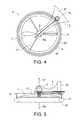
- FIG. 4is a schematic top view of an embodiment of a rotor and wheel assembly of the present invention, as installed on the embodiment of the vehicle apparatus of FIG. 1 ;
- FIG. 5is a schematic front view of the embodiment of the rotor and wheel assembly of FIG. 4 ;
- FIG. 6is a schematic front view of the embodiment of FIG. 1 shown in the ground position, and illustrating the orientation and relative magnitudes of the force components exerted by the spinning rotor;
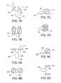
- FIGS. 7A and 7Brespectively show front and top views of an alternate fixed arm two rotor/wheel embodiment of an unmanned vehicle apparatus of the present invention shown in the flying position;
- FIGS. 7C and 7Drespectively show side and top views of the fixed two rotor/wheel embodiment of FIGS. 7A , 7 B shown in the ground position;
- FIGS. 8A and 8Brespectively show respectively show front and top views of an alternate pivoting arm two rotor/wheel embodiment of an unmanned vehicle apparatus of the present invention shown in the flying position;
- FIGS. 8C and 8Drespectively show side and top views of the pivoting arm two rotor/wheel embodiment of FIGS. 8A , 8 B shown in the ground position;
- FIGS. 9A and 9Brespectively show respectively show front and top views of an alternate pivoting arm three rotor/wheel embodiment of an unmanned vehicle apparatus of the present invention shown in the flying position;
- FIGS. 9C and 9Drespectively show side and top views of the pivoting arm three rotor/wheel embodiment of FIGS. 9A , 9 B shown in the ground position;
- FIGS. 10A and 10Brespectively show respectively show front and top views of an alternate pivoting arm six rotor/wheel embodiment of an unmanned vehicle apparatus of the present invention shown in the flying position;
- FIGS. 10C and 10Drespectively show side and top views of the pivoting arm six rotor/wheel embodiment of FIGS. 10A , 10 B shown in the ground position;
- FIG. 11is a schematic top view of an alternate embodiment of a rotor and wheel assembly of the present invention.
- FIG. 12is a schematic front view of the embodiment of the rotor and wheel assembly of FIG. 11 ;
- FIGS. 13A-13Cschematically illustrate front views of an alternate embodiment of an unmanned vehicle apparatus of the present invention shown in the flying, ground, and stored positions;
- FIGS. 14A-14Cschematically illustrate front views of another alternate embodiment of an unmanned vehicle apparatus of the present invention shown in the flying, ground, and stored positions.
- FIGS. 1-3schematically illustrate an embodiment of an unmanned vehicle apparatus 1 of the present invention.
- the apparatus 1comprises a vehicle body 3 and right and left rotor and wheel assemblies 4 R, 4 L extending from corresponding right and left sides of the vehicle body 3 .
- Each rotor and wheel assembly 4comprises a rotor arm 5 adapted to be attached at an inner end thereof to the vehicle body 3 , and a rotor 7 rotatably connected to an outer end of the rotor arm 5 about a rotor axis RA, and a rotor drive is mounted on the rotor arm operative to rotate the rotor 7 such that the rotor exerts an upward lift force LF on the rotor arm 5 in the direction of the rotational axis RA.
- the rotor driveis provided by a rotor motor 9 mounted on the rotor arm 5 and connected directly to the rotor 7 .
- An open spoked wheel 11is rotatably connected to the outer end of the rotor arm 5 about the rotor axis RA independent of the rotor 7 .
- the diameter of the wheel 11is greater than the diameter of the rotor 7 , and a bottom edge 13 of the wheel 11 is below the rotor 7 .
- the open spoked structure of the wheel 11allows air to flow freely to the rotor 7 to provide lift when flying.
- a wheel driveis mounted on the arm and operative to rotate the wheel 11 .
- the wheel 11comprises an annular rim 15 connected by spokes 17 to a hub 19 that is rotatably attached to the end of the arm 5 , and an annular tread member 21 is connected to the rim 15 below the rim and concentric with the rim such that the bottom edge 13 of the wheel is provided by the tread member 21 .
- the rims 15 on front wheels 11 RF, 11 LF on the front rotor and wheel assemblies 4 RF, 4 LFdefine gear teeth 23 and the wheel drive is provided by a wheel motor 25 mounted on each corresponding front rotor arm 5 RF, 5 LF with a sprocket 27 mounted on the motor shaft that is operative to engage the gear teeth 23 to rotate the front wheels 11 RF, 11 LF.
- the rotor 7thus rotates in a protected plane just below the rim 15 and above the tread member 21 .
- the diameter of the rotor 7is about the same as the inside diameter of the tread member 21 .
- combination rotor and wheel assembly 4can be used in various ways to provide an unmanned vehicle with ground and aerial mobility, for example a vehicle with only two rotor and wheel assemblies, one on the right and one on the left side of the body, could conceivably operate satisfactorily. Such alternative embodiments are discussed below.
- the illustrated apparatus 1however, for increased stability, has four rotor and wheel assemblies 4 illustrated as front and rear right rotor and wheel assemblies 4 RF, 4 RR and front and rear left rotor and wheel assemblies 4 LF, 4 LR.
- the right wheel 11 RF on the right side and the left wheel 11 LF on the left sideare driven at variable speeds independently of each other.
- the right and left front and rear rotor and wheel assemblies 4 RF, 4 RR, 4 LF, 4 LRare oriented such that the bottom edges 13 of the wheels 11 support the vehicle body 3 for movement along the ground, and such that rotating or spinning the rotors 7 provides a lift force operative to raise the vehicle body 3 and attached rotor and wheel assemblies 4 above the ground.
- a remote rotor control 29is operative to independently vary the rotational speed of the rotor motors 9 to provide flight control
- a remote wheel control 31is operative to independently vary the rotational speed of the wheel motors 25 to provide ground propulsion and steering control.
- FIGS. 3 and 6schematically illustrate a front view of the apparatus 1 showing the bottom edges of the wheels 13 resting on the ground, and the rotor axes RA tilted at an angle N of about 40 degrees down from vertical.
- Operating the wheel motors 25will move the apparatus 1 along the ground, and varying the speed of the wheel 11 on one side relative to that on the other side provides steering control.
- the arms 5 of each of the rotor and wheel assemblies 4are pivotally mounted to the body 3 , and an arm actuator 33 is operative to pivot the arms 5 of the rotor and wheel assemblies 4 from the flying position shown in FIG. 2 , where the rotor axes RA are in an upright orientation, to the ground position shown in FIG. 3 where the rotor axes RA are in a lateral orientation.
- the rotor axes RAwhen in the flying position the rotor axes RA will be oriented within about 10 degrees of vertical. With an angle of 10 degrees, the actual upward lift component of LF will be about 98% of the force LF generated by the rotor 7 , significantly increasing the lift capabilities compared to an angle of 40 degrees.
- the rotational axes RAWhen in the ground position, the rotational axes RA could be tilted down to 90 degrees from vertical, such that the rotational axes RA are horizontal and the wheels are oriented vertically as in a conventional vehicle.
- FIGS. 13C and 14C described belowshow such an orientation which is convenient for storage and portability of the apparatus 1 .
- the mechanism of the arm actuator 33can be simplified by reducing the downward tilt to between about 30 degrees and about 50 degrees downward from vertical when in the ground position, and still be satisfactory.
- the wider stance between the contact points of the wheels and ground on right and left sides when the arms are oriented between about 30 degrees and about 50 degreesalso increases the stability of the apparatus in the ground position.
- the front and rear right rotor arms 5 RF, 5 RRare mounted to a right arm plate 35 R and oriented such that front and rear right rotor axes RARE.
- RARRare substantially parallel
- corresponding front and rear right wheels 11 RF, 11 RRare aligned and oriented to roll in a ground operating travel direction T
- the right arm plate 35 Ris pivotally attached to a lower portion of the vehicle body 3 about a plate pivot axis PPA oriented substantially in alignment with the ground operating travel direction T.
- front and rear left rotor arms 5 LF, 5 LRare mounted to a left arm plate 35 L and oriented such that front and rear left rotor axes RALF, RALR are substantially parallel, corresponding front and rear left wheels 11 LF, 11 LR are aligned and oriented to roll in the ground operating travel direction T, and the left arm plate 35 L is pivotally attached to the vehicle body 3 about the same plate pivot axis PPA.
- the right and left plate pivot axes PPA for the corresponding right and left arm plates 35 R, 35 Lcoincide, however it is contemplated that they could be separated by a distance, as shown for example in FIG. 14A described below.
- the arm actuator 33is operative to pivot both the right and left arm plates 35 R, 35 L simultaneously from the flying position shown in FIG. 2 where the rotor axes RA are in an upright orientation, to the ground position shown in FIG. 3 where the rotor axes RA are in a lateral orientation.
- the arms 5are thus controlled simply by a single mechanism, again operated by a remote arm control 37 .
- FIGS. 7A-10Dschematically illustrate a vehicle apparatus 101 with two fixed rotor and wheel assemblies 104 , with arms 105 fixed to right and left sides of the body 103 .
- the spinning rotors 107create a lift force LF and the lateral orientation of the rotational axes RA results in an actual upward lift component LF′ which will be calculated to be sufficient to lift the apparatus 101 such that the tail end 141 of the body 103 hangs down.
- the wheels 111are oriented for ground travel and the tail end 141 drags on the ground on a skid surface, or a small wheel could be provided as well depending on the application.
- FIGS. 8A-8Dschematically illustrate a vehicle apparatus 201 with two pivoting rotor and wheel assemblies 204 , with arms 205 pivotally attached to right and left sides of the body 203 .
- the spinning rotors 207create a lift force LF and the rotational axes RA are oriented substantially vertically so that all the lift force LF exerts an upward force to lift the apparatus 201 into the air with the tail end 241 of the body 203 hanging down.
- the wheels 211are pivoted to an orientation for ground travel and the tail end 241 again drags on the ground.
- FIGS. 9A-9Dschematically illustrate a vehicle apparatus 301 with three pivoting rotor and wheel assemblies 304 , with arms 305 pivotally attached to the body 303 and substantially equally spaced around the body 303 .
- the spinning rotors 307create a lift force LF and the rotational axes RA are oriented substantially vertically so that all the lift force LF exerts an upward force to lift the apparatus 301 into the air.
- the wheels 311are pivoted to an orientation for ground travel.
- FIGS. 10A-10Dschematically illustrate a vehicle apparatus 401 with six pivoting rotor and wheel assemblies 404 , with arms 405 pivotally attached to the body 403 and substantially equally spaced around the body 403 .
- the spinning rotors 407create a lift force LF and the rotational axes RA are oriented substantially vertically so that all the lift force LF exerts an upward force to lift the apparatus 401 into the air.
- the wheels 411are pivoted to an orientation for ground travel.
- Wheels on the right and left sideswould be rotated at variable speeds independently of each other to provide directional steering control for ground travel.
- Other numbers and orientations of rotor and wheel assembliesare contemplated and as well, additional fixed conventional rotors could be attached to the body where increased lift was desired.
- the rotor and wheel assembliesare attached in selected numbers and orientations to suit the particular application being pursued, either fixed or pivotally, to a vehicle body to provide vehicles, such as the unmanned vehicle apparatuses 1 , 101 , 201 , 301 , 401 described above, that have both aerial and ground mobility.
- FIGS. 11 and 12schematically illustrate an alternate embodiment of a rotor and wheel assembly 504 of the present invention.
- the wheel 511comprises an annular fixed rim 515 connected by spokes 517 to a hub 519 that is fixed to the arm 505 at the rotor axis RA, instead of being rotatably attached at the rotor axis as in the rotor and wheel assembly 4 described above.
- an annular tread member 521is rotatable on the outer surface of the fixed rim 515 and only the tread member rotates about the rotor axis.
- the bottom edge of the wheel 511is provided by the tread member 521 .
- the rotor driveis provided by a rotor motor 509 mounted on the rotor arm 505 and connected directly to the rotor 507 which rotates inside the wheel 511 , and above the bottom of the wheel 111 such that the rotor blades are protected from contact with walls or the like when flying.
- the open spoked structure of the wheel 511allows air to flow freely to the rotor 507 to provide lift when flying.
- the fixed rim 515defines gear teeth 523 and the wheel drive is provided by a wheel motor 525 mounted on rotor arm 505 with a sprocket 527 mounted on the motor shaft that is operative to engage the gear teeth 523 to rotate the tread member 521 on the fixed rim 515 .
- FIGS. 13A-13Cschematically illustrate an alternate apparatus 601 that is movable to a stored position where the rotor arms 605 of the right and left rotor and wheel assemblies 604 are movable from the flying position of FIG. 13A to the ground position of FIG. 13B to a stored position shown in FIG. 13C where the rotor axes RA of the rotor and wheel assemblies 604 are oriented substantially horizontally.
- FIGS. 14A-14Cschematically illustrate a further alternate apparatus 701 that is movable to a stored position where the rotor arms 705 of the right and left rotor and wheel assemblies 704 pivot about separated pivot axes RPA, LPA and are again movable from the flying position of FIG. 14A to the ground position of FIG. 14B to the stored position shown in FIG. 14C where the rotor axes RA are oriented substantially horizontally.
Landscapes
- Engineering & Computer Science (AREA)
- Aviation & Aerospace Engineering (AREA)
- Mechanical Engineering (AREA)
- Remote Sensing (AREA)
- Transportation (AREA)
- Arrangement Or Mounting Of Propulsion Units For Vehicles (AREA)
Abstract
Description
Claims (24)
Priority Applications (1)
| Application Number | Priority Date | Filing Date | Title |
|---|---|---|---|
| US14/641,468US9598171B2 (en) | 2012-08-29 | 2015-03-09 | Vehicle with aerial and ground mobility |
Applications Claiming Priority (2)
| Application Number | Priority Date | Filing Date | Title |
|---|---|---|---|
| CA2787279ACA2787279C (en) | 2012-08-29 | 2012-08-29 | Vehicle with aerial and ground mobility |
| CA2787279 | 2012-08-29 |
Related Child Applications (1)
| Application Number | Title | Priority Date | Filing Date |
|---|---|---|---|
| US14/641,468DivisionUS9598171B2 (en) | 2012-08-29 | 2015-03-09 | Vehicle with aerial and ground mobility |
Publications (2)
| Publication Number | Publication Date |
|---|---|
| US20140061362A1 US20140061362A1 (en) | 2014-03-06 |
| US8991740B2true US8991740B2 (en) | 2015-03-31 |
Family
ID=47087787
Family Applications (2)
| Application Number | Title | Priority Date | Filing Date |
|---|---|---|---|
| US13/846,074ActiveUS8991740B2 (en) | 2012-08-29 | 2013-03-18 | Vehicle with aerial and ground mobility |
| US14/641,468Active2033-03-29US9598171B2 (en) | 2012-08-29 | 2015-03-09 | Vehicle with aerial and ground mobility |
Family Applications After (1)
| Application Number | Title | Priority Date | Filing Date |
|---|---|---|---|
| US14/641,468Active2033-03-29US9598171B2 (en) | 2012-08-29 | 2015-03-09 | Vehicle with aerial and ground mobility |
Country Status (2)
| Country | Link |
|---|---|
| US (2) | US8991740B2 (en) |
| CA (1) | CA2787279C (en) |
Cited By (78)
| Publication number | Priority date | Publication date | Assignee | Title |
|---|---|---|---|---|
| US20150093956A1 (en)* | 2012-06-07 | 2015-04-02 | Witold Mielniczek | Propulsion system for a vehicle or a toy vehicle |
| USD751025S1 (en)* | 2014-06-13 | 2016-03-08 | Bcb International Limited | Unmanned aerial vehicle |
| USD751490S1 (en)* | 2014-06-12 | 2016-03-15 | SZ DJI Technology Co., Ltd. | Aircraft |
| USD759764S1 (en)* | 2014-11-18 | 2016-06-21 | Thunder Tiger Corporation | Quadcopter |
| USD761690S1 (en)* | 2014-11-06 | 2016-07-19 | Dronesmith Technologies, Inc. | Unmanned aerial vehicle |
| US20170029103A1 (en)* | 2015-07-28 | 2017-02-02 | Inventec Appliances (Pudong) Corporation | Unmanned vehicle |
| US9598171B2 (en) | 2012-08-29 | 2017-03-21 | Zenon Dragon | Vehicle with aerial and ground mobility |
| USD784854S1 (en)* | 2015-11-02 | 2017-04-25 | Shenzhen Rapoo Technology Co., Ltd. | Unmanned aircraft |
| US9630710B2 (en)* | 2014-10-29 | 2017-04-25 | Qualcomm Incorporated | Unmanned aerial vehicle |
| KR101747593B1 (en)* | 2016-01-11 | 2017-06-14 | 한국항공우주연구원 | Drone adapter |
| WO2017126820A1 (en)* | 2016-01-20 | 2017-07-27 | 한국전력공사 | Variable flying robot |
| KR101782741B1 (en)* | 2016-07-14 | 2017-09-28 | 한국항공우주연구원 | Drone and drone's landing system comprising the drone |
| US20170313418A1 (en)* | 2014-10-08 | 2017-11-02 | Hanwha Techwin Co., Ltd. | Unmanned vehicle |
| US9875251B2 (en) | 2015-06-02 | 2018-01-23 | GeoFrenzy, Inc. | Geofence information delivery systems and methods |
| CN107719048A (en)* | 2017-09-05 | 2018-02-23 | 淮阴工学院 | Land and air double-used motor aircraft |
| US9906902B2 (en) | 2015-06-02 | 2018-02-27 | GeoFrenzy, Inc. | Geofence information delivery systems and methods |
| US9906905B2 (en) | 2015-06-02 | 2018-02-27 | GeoFrenzy, Inc. | Registration mapping toolkit for geofences |
| US9906609B2 (en) | 2015-06-02 | 2018-02-27 | GeoFrenzy, Inc. | Geofence information delivery systems and methods |
| US20180086442A1 (en)* | 2014-09-02 | 2018-03-29 | Amit REGEV | Tilt Winged Multi Rotor |
| USD816581S1 (en)* | 2016-12-06 | 2018-05-01 | Jianjia Zhao | Quadcopter |
| US9986378B2 (en) | 2014-07-29 | 2018-05-29 | GeoFrenzy, Inc. | Systems and methods for defining and implementing rules for three dimensional geofences |
| USD825669S1 (en) | 2017-07-10 | 2018-08-14 | MerchSource, LLC | Drone car |
| USD825380S1 (en) | 2017-06-27 | 2018-08-14 | MerchSource, LLC | Drone for kids |
| US10115277B2 (en) | 2014-07-29 | 2018-10-30 | GeoFrenzy, Inc. | Systems and methods for geofence security |
| US10121215B2 (en) | 2014-07-29 | 2018-11-06 | GeoFrenzy, Inc. | Systems and methods for managing real estate titles and permissions |
| KR20180127869A (en)* | 2017-05-22 | 2018-11-30 | 주식회사 케이엠씨로보틱스 | Hybrid drone capable of traveling on the ground and flying havign suspension ability |
| US10237232B2 (en) | 2014-07-29 | 2019-03-19 | GeoFrenzy, Inc. | Geocoding with geofences |
| US10235726B2 (en) | 2013-09-24 | 2019-03-19 | GeoFrenzy, Inc. | Systems and methods for secure encryption of real estate titles and permissions |
| USD846440S1 (en)* | 2016-10-18 | 2019-04-23 | Samsung Electronics Co., Ltd. | Drone |
| USD846445S1 (en) | 2017-09-15 | 2019-04-23 | MerchSource, LLC | Drone |
| USD846444S1 (en)* | 2016-10-18 | 2019-04-23 | Samsung Electronics Co., Ltd. | Drone |
| USD846438S1 (en)* | 2016-10-18 | 2019-04-23 | Samsung Electronics Co., Ltd. | Drone |
| USD846441S1 (en)* | 2016-10-18 | 2019-04-23 | Samsung Electronics Co., Ltd. | Drone |
| USD846442S1 (en)* | 2016-10-18 | 2019-04-23 | Samsung Electronics Co., Ltd. | Drone |
| USD846443S1 (en)* | 2016-10-18 | 2019-04-23 | Samsung Electronics Co., Ltd. | Drone |
| USD846437S1 (en)* | 2016-10-18 | 2019-04-23 | Samsung Electronics Co., Ltd. | Drone |
| USD846439S1 (en)* | 2016-10-18 | 2019-04-23 | Samsung Electronics Co., Ltd. | Drone |
| USD847019S1 (en)* | 2016-10-18 | 2019-04-30 | Samsung Electronics Co., Ltd. | Drone |
| USD847021S1 (en)* | 2016-10-18 | 2019-04-30 | Samsung Electroncis Co., Ltd. | Drone |
| USD847020S1 (en)* | 2016-10-18 | 2019-04-30 | Samsung Electronics Co., Ltd. | Drone |
| USD847017S1 (en)* | 2016-10-18 | 2019-04-30 | Samsung Electronics Co., Ltd. | Drone |
| USD847018S1 (en)* | 2016-10-18 | 2019-04-30 | Samsung Electronics Co., Ltd. | Drone |
| USD851540S1 (en) | 2017-06-07 | 2019-06-18 | MerchSource, LLC | Drone |
| USD852091S1 (en) | 2017-07-20 | 2019-06-25 | MerchSource, LLC | Drone |
| US10358214B2 (en) | 2015-01-04 | 2019-07-23 | Hangzhou Zero Zro Technology Co., Ltd. | Aerial vehicle and method of operation |
| US10375514B2 (en) | 2014-07-29 | 2019-08-06 | GeoFrenzy, Inc. | Systems, methods and apparatus for geofence networks |
| USD862359S1 (en) | 2016-10-27 | 2019-10-08 | SZ DJI Technology Co., Ltd. | Aerial vehicle |
| USD862285S1 (en) | 2017-08-25 | 2019-10-08 | MerchSource, LLC | Drone |
| US10582333B2 (en) | 2014-07-29 | 2020-03-03 | GeoFrenzy, Inc. | Systems and methods for geofence security |
| US10675932B2 (en) | 2017-03-08 | 2020-06-09 | Toyota Motor Engineering & Manufacturing North America, Inc. | Dual-mode vehicle with wheel rotors |
| US10723189B2 (en)* | 2016-07-26 | 2020-07-28 | Ford Global Technologies Llc | Personal transportation devices having a driving configuration and a flying configuration |
| US10745125B2 (en)* | 2017-07-27 | 2020-08-18 | Tatsumi Ryoki Co., Ltd | Hovering vehicle |
| US10787256B2 (en) | 2016-01-29 | 2020-09-29 | Lta Corporation | Aeronautical car and associated features |
| US10805761B2 (en) | 2014-07-29 | 2020-10-13 | GeoFrenzy, Inc. | Global registration system for aerial vehicles |
| US10824167B2 (en) | 2015-01-04 | 2020-11-03 | Hangzhou Zero Zero Technology Co., Ltd. | System and method for automated aerial system operation |
| US10824149B2 (en) | 2015-01-04 | 2020-11-03 | Hangzhou Zero Zero Technology Co., Ltd. | System and method for automated aerial system operation |
| USD902078S1 (en) | 2017-06-07 | 2020-11-17 | MerchSource, LLC | Drone |
| US10932084B2 (en) | 2014-07-29 | 2021-02-23 | GeoFrenzy, Inc. | Systems, methods and apparatus for geofence networks |
| JPWO2020196733A1 (en)* | 2019-03-28 | 2021-04-08 | 有限会社渥美不動産アンドコーポレーション | Flight device with a tubular rotating body |
| US10979849B2 (en) | 2015-06-02 | 2021-04-13 | GeoFrenzy, Inc. | Systems, methods and apparatus for geofence networks |
| US11027833B2 (en) | 2016-04-24 | 2021-06-08 | Hangzhou Zero Zero Technology Co., Ltd. | Aerial system propulsion assembly and method of use |
| US20220017220A1 (en)* | 2018-12-12 | 2022-01-20 | Jin Sik BAE | Movable device usable for cleaning and movable device control method |
| US11240628B2 (en) | 2014-07-29 | 2022-02-01 | GeoFrenzy, Inc. | Systems and methods for decoupling and delivering geofence geometries to maps |
| US11247089B2 (en) | 2019-08-22 | 2022-02-15 | Robotic Research Opco, Llc | Chemical and biological warfare agent decontamination drone |
| US11254430B2 (en) | 2014-09-02 | 2022-02-22 | Amit REGEV | Tilt winged multi rotor |
| US11267568B2 (en)* | 2017-10-11 | 2022-03-08 | Hangzhou Zero Zero Technology Co., Ltd. | Aerial system including foldable frame architecture |
| US11340618B2 (en) | 2019-08-08 | 2022-05-24 | Robotic Research Opco, Llc | Drone based inspection system at railroad crossings |
| US11338634B1 (en)* | 2014-10-30 | 2022-05-24 | Robotic Research Opco, Llc | Vehicle capable of multiple varieties of locomotion |
| US11575648B2 (en) | 2014-07-29 | 2023-02-07 | GeoFrenzy, Inc. | Geocoding with geofences |
| US11606666B2 (en) | 2014-07-29 | 2023-03-14 | GeoFrenzy, Inc. | Global registration system for aerial vehicles |
| US11838744B2 (en) | 2014-07-29 | 2023-12-05 | GeoFrenzy, Inc. | Systems, methods and apparatus for geofence networks |
| WO2024106648A1 (en)* | 2022-11-15 | 2024-05-23 | 주식회사 딥블루익스플로러 | System capable of converting air drone to maritime or land drone |
| US12022352B2 (en) | 2014-07-29 | 2024-06-25 | GeoFrenzy, Inc. | Systems, methods and apparatus for geofence networks |
| US12077027B2 (en) | 2018-08-14 | 2024-09-03 | Everon Corporation | Personal auto-craft having automobile and vertical take-off configurations |
| US12091163B2 (en)* | 2020-06-02 | 2024-09-17 | Flir Unmanned Aerial Systems Ulc | Locomotion systems and methods for aerial vehicles |
| US12302191B2 (en) | 2014-07-29 | 2025-05-13 | GeoFrenzy, Inc. | Systems and methods for decoupling and delivering geofence geometries to maps |
| US12337635B2 (en) | 2021-04-08 | 2025-06-24 | Thius Canada Inc. | Multi-mode convertible vehicle |
| US12387578B2 (en) | 2014-07-29 | 2025-08-12 | GeoFrenzy, Inc. | Systems and methods for geofence security |
Families Citing this family (54)
| Publication number | Priority date | Publication date | Assignee | Title |
|---|---|---|---|---|
| FR2973335B1 (en)* | 2011-03-29 | 2013-04-19 | Inst Superieur De L Aeronautique Et De L Espace | MICRO / NANO REMOTE CONTROL VEHICLE COMPRISING A SYSTEM FOR FLOOR, VERTICAL TAKEOFF AND LANDING |
| US9384668B2 (en) | 2012-05-09 | 2016-07-05 | Singularity University | Transportation using network of unmanned aerial vehicles |
| US9061558B2 (en)* | 2012-11-14 | 2015-06-23 | Illinois Institute Of Technology | Hybrid aerial and terrestrial vehicle |
| CA2997790C (en)* | 2013-05-15 | 2021-06-29 | Autel Robotics Usa Llc | Compact unmanned rotary aircraft |
| US9580172B2 (en)* | 2013-09-13 | 2017-02-28 | Sandia Corporation | Multiple environment unmanned vehicle |
| US10723442B2 (en) | 2013-12-26 | 2020-07-28 | Flir Detection, Inc. | Adaptive thrust vector unmanned aerial vehicle |
| US10839336B2 (en) | 2013-12-26 | 2020-11-17 | Flir Detection, Inc. | Unmanned delivery |
| US9764835B1 (en)* | 2014-04-02 | 2017-09-19 | Amazon Technologies, Inc. | Aerial vehicle configuration |
| US9754496B2 (en) | 2014-09-30 | 2017-09-05 | Elwha Llc | System and method for management of airspace for unmanned aircraft |
| US9688400B2 (en) | 2014-10-29 | 2017-06-27 | Qualcomm Incorporated | Unmanned aerial vehicle |
| US9550400B2 (en)* | 2014-10-29 | 2017-01-24 | Qualcomm Incorporated | Unmanned aerial vehicle |
| US9623968B2 (en) | 2014-11-11 | 2017-04-18 | Jon RIMANELLI | Unmanned air-ground vehicle |
| US20160272310A1 (en)* | 2014-12-04 | 2016-09-22 | Elwha Llc | Reconfigurable unmanned aircraft system |
| US9919797B2 (en) | 2014-12-04 | 2018-03-20 | Elwha Llc | System and method for operation and management of reconfigurable unmanned aircraft |
| US10719080B2 (en) | 2015-01-04 | 2020-07-21 | Hangzhou Zero Zero Technology Co., Ltd. | Aerial system and detachable housing |
| US10220954B2 (en) | 2015-01-04 | 2019-03-05 | Zero Zero Robotics Inc | Aerial system thermal control system and method |
| CN204998752U (en)* | 2015-01-04 | 2016-01-27 | 北京零零无限科技有限公司 | Folding unmanned aerial vehicle |
| US9469394B2 (en)* | 2015-03-10 | 2016-10-18 | Qualcomm Incorporated | Adjustable weight distribution for drone |
| GB201509509D0 (en)* | 2015-06-01 | 2015-07-15 | Imp Innovations Ltd | Aerial devices capable of controlled flight |
| US9878787B2 (en) | 2015-07-15 | 2018-01-30 | Elwha Llc | System and method for operating unmanned aircraft |
| EP3374263A4 (en)* | 2015-11-10 | 2019-05-08 | Matternet, Inc. | METHODS AND TRANSPORT SYSTEMS USING PILOT-FREE AIR VEHICLES |
| KR102158762B1 (en)* | 2015-11-18 | 2020-09-22 | 한국전자기술연구원 | Propulsion equipment for flying and driving of vehicle |
| US10162348B1 (en)* | 2016-02-04 | 2018-12-25 | United Services Automobile Association (Usaa) | Unmanned vehicle morphing |
| EP3419894B1 (en) | 2016-02-22 | 2021-11-10 | SZ DJI Technology Co., Ltd. | Foldable multi-rotor aerial vehicle |
| USD779595S1 (en)* | 2016-04-06 | 2017-02-21 | Guangdong Syma Model Aircraft Industrial Co., Ltd | Toy aircraft |
| CN105774447B (en)* | 2016-04-22 | 2018-02-27 | 马渝皓 | Aeroamphibious three are dwelt concept car |
| US10331132B2 (en) | 2016-07-25 | 2019-06-25 | Foster-Miller, Inc. | Remotely controlled robot |
| WO2018119620A1 (en)* | 2016-12-27 | 2018-07-05 | 深圳市大疆创新科技有限公司 | Multi-rotor unmanned aerial vehicle |
| US20180281537A1 (en)* | 2017-01-03 | 2018-10-04 | Joshua Leppo | Multi-Dimensional Vehicle |
| US10067513B2 (en) | 2017-01-23 | 2018-09-04 | Hangzhou Zero Zero Technology Co., Ltd | Multi-camera system and method of use |
| CN107139664A (en)* | 2017-05-05 | 2017-09-08 | 北京普拉斯科技发展有限公司 | A kind of aerocycle and system |
| WO2018213836A1 (en)* | 2017-05-19 | 2018-11-22 | The Texas A&M University System | Multi-modal vehicle |
| US9957045B1 (en)* | 2017-09-03 | 2018-05-01 | Brehnden Daly | Stackable drones |
| FR3070607B1 (en)* | 2017-09-07 | 2020-09-04 | Parrot Drones | ROTATING BLADE DRONE INCLUDING A FOLDABLE DRONE STRUCTURE |
| US11267555B2 (en)* | 2018-01-08 | 2022-03-08 | GEOSAT Aerospace & Technology | Methods and unmanned aerial vehicles for longer duration flights |
| US11660920B2 (en) | 2018-02-28 | 2023-05-30 | Stmicroelectronics S.R.L. | Multi-environment flexible vehicle |
| CN108715118A (en)* | 2018-06-15 | 2018-10-30 | 中宇航通(北京)科技有限公司 | A kind of hovercar tandem double-vane extension and retraction system and hovercar |
| CN112533825B (en)* | 2018-08-24 | 2024-08-02 | 杭州零零科技有限公司 | Detachable protection structure for unmanned aerial system |
| DE102019001130B3 (en)* | 2019-02-13 | 2020-02-13 | Friedrich Grimm | Wheel propellers and vehicles with wheel propellers |
| FR3093994B1 (en)* | 2019-03-18 | 2021-06-11 | Airbus Helicopters | Method and device for moving a center of gravity of an aircraft |
| DE102019120492B3 (en) | 2019-07-30 | 2020-07-30 | Dr. Ing. H.C. F. Porsche Aktiengesellschaft | vehicle |
| GB2586835B (en)* | 2019-09-05 | 2022-04-27 | Rallings Alan | Motor vehicles for use on the ground and in the air |
| EP4592189A3 (en)* | 2019-10-09 | 2025-09-03 | Kitty Hawk Corporation | Hybrid power systems for different modes of flight |
| US11909279B1 (en)* | 2020-09-16 | 2024-02-20 | Charles Scott Wright | Prime mover with integral drivers for providing multiple modes of locomotion |
| CN112078299B (en)* | 2020-10-13 | 2024-09-10 | 河北工业大学 | Rotatable rotation-revolution amphibious application gear train |
| CN112339515B (en)* | 2020-11-09 | 2022-04-08 | 北京理工大学 | A split car and its passenger compartment, aircraft unit and chassis part |
| CN112677724A (en)* | 2021-01-28 | 2021-04-20 | 江西科技学院 | Flying automobile |
| CN113147292B (en)* | 2021-04-25 | 2022-09-23 | 安徽索骥智能科技有限公司 | Deformable triphibian obstacle crossing robot for water, land and air |
| CN113276613A (en)* | 2021-06-17 | 2021-08-20 | 北京理工大学 | Configuration-variable air-ground unmanned platform capable of air-ground joint debugging |
| US12344407B2 (en)* | 2021-11-15 | 2025-07-01 | California Institute Of Technology | Multi-modal mobility unmanned vehicle |
| US12145753B2 (en)* | 2022-08-09 | 2024-11-19 | Pete Bitar | Compact and lightweight drone delivery device called an ArcSpear electric jet drone system having an electric ducted air propulsion system and being relatively difficult to track in flight |
| CN116552808A (en)* | 2023-06-02 | 2023-08-08 | 上海交通大学 | Feiyue Walking Integrated Mechanism |
| US12384536B2 (en)* | 2024-01-05 | 2025-08-12 | City University Of Hong Kong | Reconfigurable quadrotor with controlled rolling and turning |
| CN119872948A (en)* | 2024-12-25 | 2025-04-25 | 广东工业大学 | Unmanned aerial vehicle driving module capable of switching water and air paddles, unmanned aerial vehicle and switching method |
Citations (17)
| Publication number | Priority date | Publication date | Assignee | Title |
|---|---|---|---|---|
| US769721A (en)* | 1903-07-09 | 1904-09-13 | George W Thompson | Flying-machine. |
| US1031797A (en)* | 1906-10-30 | 1912-07-09 | John M Janesone | Aeroplane. |
| US1777941A (en)* | 1929-01-12 | 1930-10-07 | Szakacs Joseph | Unicycle glider |
| US3147936A (en)* | 1960-09-27 | 1964-09-08 | Mcdonnell Aircraft Corp | Dual configuration vehicle |
| US3874618A (en)* | 1970-05-26 | 1975-04-01 | Kenneth Clayton Bates | Combination of a rotary prime mover-compressor with a vehicle, such as an aircraft |
| US5454531A (en)* | 1993-04-19 | 1995-10-03 | Melkuti; Attila | Ducted propeller aircraft (V/STOL) |
| US5895011A (en)* | 1997-06-24 | 1999-04-20 | Gubin; Daniel | Turbine airfoil lifting device |
| US6144180A (en) | 1999-07-09 | 2000-11-07 | Chen; Chun-Ta | Mobile robot |
| US6398160B1 (en)* | 2000-07-17 | 2002-06-04 | Chih-Yu Hsia | Inflatable airfoils, and elevated and propulsion driven vehicles |
| US6588701B2 (en) | 2000-09-26 | 2003-07-08 | Rafael Armament Development Authority, Ltd. | Unmanned mobile device |
| US7510142B2 (en) | 2006-02-24 | 2009-03-31 | Stealth Robotics | Aerial robot |
| US20100181414A1 (en)* | 2009-01-21 | 2010-07-22 | Lopez Jr Ignacio | Personal transportation vehicle |
| US7959104B2 (en) | 2004-12-23 | 2011-06-14 | Julian Kuntz | Flying device with improved movement on the ground |
| US20110139923A1 (en)* | 2009-12-10 | 2011-06-16 | Papanikolopoulos Nikolaos P | Miniature Robotic Vehicle with Ground and Flight Capability |
| US8205820B2 (en) | 2009-02-03 | 2012-06-26 | Honeywell International Inc. | Transforming unmanned aerial-to-ground vehicle |
| US8794564B2 (en)* | 2012-08-02 | 2014-08-05 | Neurosciences Research Foundation, Inc. | Vehicle capable of in-air and on-ground mobility |
| US8794566B2 (en)* | 2012-08-02 | 2014-08-05 | Neurosciences Research Foundation, Inc. | Vehicle capable of stabilizing a payload when in motion |
Family Cites Families (5)
| Publication number | Priority date | Publication date | Assignee | Title |
|---|---|---|---|---|
| JPH074452B2 (en)* | 1990-05-17 | 1995-01-25 | ジャルデータ通信株式会社 | Radio-controlled flying vehicle |
| US7712701B1 (en)* | 2006-02-10 | 2010-05-11 | Lockheed Martin Corporation | Unmanned aerial vehicle with electrically powered, counterrotating ducted rotors |
| US8011614B2 (en)* | 2007-04-10 | 2011-09-06 | Bird Stanley W | Bird vortex flying machine |
| US20100224723A1 (en)* | 2009-03-03 | 2010-09-09 | Jacob Apkarian | Aerial vehicle |
| CA2787279C (en) | 2012-08-29 | 2013-10-22 | Draganfly Holdings Inc. | Vehicle with aerial and ground mobility |
- 2012
- 2012-08-29CACA2787279Apatent/CA2787279C/enactiveActive
- 2013
- 2013-03-18USUS13/846,074patent/US8991740B2/enactiveActive
- 2015
- 2015-03-09USUS14/641,468patent/US9598171B2/enactiveActive
Patent Citations (17)
| Publication number | Priority date | Publication date | Assignee | Title |
|---|---|---|---|---|
| US769721A (en)* | 1903-07-09 | 1904-09-13 | George W Thompson | Flying-machine. |
| US1031797A (en)* | 1906-10-30 | 1912-07-09 | John M Janesone | Aeroplane. |
| US1777941A (en)* | 1929-01-12 | 1930-10-07 | Szakacs Joseph | Unicycle glider |
| US3147936A (en)* | 1960-09-27 | 1964-09-08 | Mcdonnell Aircraft Corp | Dual configuration vehicle |
| US3874618A (en)* | 1970-05-26 | 1975-04-01 | Kenneth Clayton Bates | Combination of a rotary prime mover-compressor with a vehicle, such as an aircraft |
| US5454531A (en)* | 1993-04-19 | 1995-10-03 | Melkuti; Attila | Ducted propeller aircraft (V/STOL) |
| US5895011A (en)* | 1997-06-24 | 1999-04-20 | Gubin; Daniel | Turbine airfoil lifting device |
| US6144180A (en) | 1999-07-09 | 2000-11-07 | Chen; Chun-Ta | Mobile robot |
| US6398160B1 (en)* | 2000-07-17 | 2002-06-04 | Chih-Yu Hsia | Inflatable airfoils, and elevated and propulsion driven vehicles |
| US6588701B2 (en) | 2000-09-26 | 2003-07-08 | Rafael Armament Development Authority, Ltd. | Unmanned mobile device |
| US7959104B2 (en) | 2004-12-23 | 2011-06-14 | Julian Kuntz | Flying device with improved movement on the ground |
| US7510142B2 (en) | 2006-02-24 | 2009-03-31 | Stealth Robotics | Aerial robot |
| US20100181414A1 (en)* | 2009-01-21 | 2010-07-22 | Lopez Jr Ignacio | Personal transportation vehicle |
| US8205820B2 (en) | 2009-02-03 | 2012-06-26 | Honeywell International Inc. | Transforming unmanned aerial-to-ground vehicle |
| US20110139923A1 (en)* | 2009-12-10 | 2011-06-16 | Papanikolopoulos Nikolaos P | Miniature Robotic Vehicle with Ground and Flight Capability |
| US8794564B2 (en)* | 2012-08-02 | 2014-08-05 | Neurosciences Research Foundation, Inc. | Vehicle capable of in-air and on-ground mobility |
| US8794566B2 (en)* | 2012-08-02 | 2014-08-05 | Neurosciences Research Foundation, Inc. | Vehicle capable of stabilizing a payload when in motion |
Cited By (130)
| Publication number | Priority date | Publication date | Assignee | Title |
|---|---|---|---|---|
| US9789415B2 (en)* | 2012-06-07 | 2017-10-17 | B-Technology Sp. Z.O.O. | Propulsion system for a vehicle or a toy vehicle |
| US9364766B2 (en)* | 2012-06-07 | 2016-06-14 | Witold Mielniczek | Propulsion system for a vehicle or a toy vehicle |
| US20150093956A1 (en)* | 2012-06-07 | 2015-04-02 | Witold Mielniczek | Propulsion system for a vehicle or a toy vehicle |
| US9598171B2 (en) | 2012-08-29 | 2017-03-21 | Zenon Dragon | Vehicle with aerial and ground mobility |
| US11651457B2 (en) | 2013-09-24 | 2023-05-16 | GeoFrenzy, Inc. | Systems and methods for secure encryption of real estate titles and permissions |
| US11062408B2 (en) | 2013-09-24 | 2021-07-13 | GeoFrenzy, Inc. | Systems and methods for secure encryption of real estate titles and permissions |
| US10580099B2 (en) | 2013-09-24 | 2020-03-03 | GeoFrenzy, Inc. | Systems and methods for secure encryption of real estate titles and permissions |
| US10235726B2 (en) | 2013-09-24 | 2019-03-19 | GeoFrenzy, Inc. | Systems and methods for secure encryption of real estate titles and permissions |
| USD751490S1 (en)* | 2014-06-12 | 2016-03-15 | SZ DJI Technology Co., Ltd. | Aircraft |
| USD751491S1 (en)* | 2014-06-12 | 2016-03-15 | SZ DJI Technology Co., Ltd. | Aircraft |
| USD751025S1 (en)* | 2014-06-13 | 2016-03-08 | Bcb International Limited | Unmanned aerial vehicle |
| US10771428B2 (en) | 2014-07-29 | 2020-09-08 | GeoFrenzy, Inc. | Geocoding with geofences |
| US10115277B2 (en) | 2014-07-29 | 2018-10-30 | GeoFrenzy, Inc. | Systems and methods for geofence security |
| US12418771B2 (en) | 2014-07-29 | 2025-09-16 | GeoFrenzy, Inc. | Systems, methods and apparatus for geofence networks |
| US12387578B2 (en) | 2014-07-29 | 2025-08-12 | GeoFrenzy, Inc. | Systems and methods for geofence security |
| US10375514B2 (en) | 2014-07-29 | 2019-08-06 | GeoFrenzy, Inc. | Systems, methods and apparatus for geofence networks |
| US12302191B2 (en) | 2014-07-29 | 2025-05-13 | GeoFrenzy, Inc. | Systems and methods for decoupling and delivering geofence geometries to maps |
| US12150006B2 (en) | 2014-07-29 | 2024-11-19 | GeoFrenzy, Inc. | Systems and methods for geofence security |
| US12143886B2 (en) | 2014-07-29 | 2024-11-12 | GeoFrenzy, Inc. | Systems, methods and apparatus for geofence networks |
| US10672244B2 (en) | 2014-07-29 | 2020-06-02 | GeoFrenzy, Inc. | Systems and methods for geofence security |
| US12022352B2 (en) | 2014-07-29 | 2024-06-25 | GeoFrenzy, Inc. | Systems, methods and apparatus for geofence networks |
| US10582333B2 (en) | 2014-07-29 | 2020-03-03 | GeoFrenzy, Inc. | Systems and methods for geofence security |
| US11871296B2 (en) | 2014-07-29 | 2024-01-09 | GeoFrenzy, Inc. | Systems and methods for decoupling and delivering geofence geometries to maps |
| US9986378B2 (en) | 2014-07-29 | 2018-05-29 | GeoFrenzy, Inc. | Systems and methods for defining and implementing rules for three dimensional geofences |
| US11838744B2 (en) | 2014-07-29 | 2023-12-05 | GeoFrenzy, Inc. | Systems, methods and apparatus for geofence networks |
| US11711666B2 (en) | 2014-07-29 | 2023-07-25 | GeoFrenzy, Inc. | Systems, methods and apparatus for geofence networks |
| US11606666B2 (en) | 2014-07-29 | 2023-03-14 | GeoFrenzy, Inc. | Global registration system for aerial vehicles |
| US11575648B2 (en) | 2014-07-29 | 2023-02-07 | GeoFrenzy, Inc. | Geocoding with geofences |
| US11240628B2 (en) | 2014-07-29 | 2022-02-01 | GeoFrenzy, Inc. | Systems and methods for decoupling and delivering geofence geometries to maps |
| US10121215B2 (en) | 2014-07-29 | 2018-11-06 | GeoFrenzy, Inc. | Systems and methods for managing real estate titles and permissions |
| US11564055B2 (en) | 2014-07-29 | 2023-01-24 | GeoFrenzy, Inc. | Systems and methods for geofence security |
| US10237232B2 (en) | 2014-07-29 | 2019-03-19 | GeoFrenzy, Inc. | Geocoding with geofences |
| US10694318B2 (en) | 2014-07-29 | 2020-06-23 | GeoFrenzy, Inc. | Systems and methods for defining and implementing rules for three dimensional geofences |
| US11523249B2 (en) | 2014-07-29 | 2022-12-06 | GeoFrenzy, Inc. | Systems, methods and apparatus for geofence networks |
| US11483671B2 (en) | 2014-07-29 | 2022-10-25 | GeoFrenzy, Inc. | Systems and methods for defining and implementing rules for three dimensional geofences |
| US11395095B2 (en) | 2014-07-29 | 2022-07-19 | GeoFrenzy, Inc. | Global registration system for aerial vehicles |
| US11393058B2 (en) | 2014-07-29 | 2022-07-19 | GeoFrenzy, Inc. | Systems and methods for managing real estate titles and permissions |
| US11356407B2 (en) | 2014-07-29 | 2022-06-07 | GeoFrenzy, Inc. | Geocoding with geofences |
| US10762587B2 (en) | 2014-07-29 | 2020-09-01 | GeoFrenzy, Inc. | Systems and methods for managing real estate titles and permissions |
| US10805761B2 (en) | 2014-07-29 | 2020-10-13 | GeoFrenzy, Inc. | Global registration system for aerial vehicles |
| US11178507B2 (en) | 2014-07-29 | 2021-11-16 | GeoFrenzy, Inc. | Systems, methods and apparatus for geofence networks |
| US11158175B2 (en) | 2014-07-29 | 2021-10-26 | GeoFrenzy, Inc. | Systems and methods for geofence security |
| US10993073B2 (en) | 2014-07-29 | 2021-04-27 | GeoFrenzy, Inc. | Systems and methods for geofence security |
| US10932084B2 (en) | 2014-07-29 | 2021-02-23 | GeoFrenzy, Inc. | Systems, methods and apparatus for geofence networks |
| US10841734B2 (en) | 2014-07-29 | 2020-11-17 | GeoFrenzy, Inc. | Systems and methods for defining and implementing rules for three dimensional geofences |
| US20180086442A1 (en)* | 2014-09-02 | 2018-03-29 | Amit REGEV | Tilt Winged Multi Rotor |
| US11254430B2 (en) | 2014-09-02 | 2022-02-22 | Amit REGEV | Tilt winged multi rotor |
| US12054253B2 (en) | 2014-09-02 | 2024-08-06 | Amit REGEV | Tilt winged multi rotor |
| US20170313418A1 (en)* | 2014-10-08 | 2017-11-02 | Hanwha Techwin Co., Ltd. | Unmanned vehicle |
| US9630710B2 (en)* | 2014-10-29 | 2017-04-25 | Qualcomm Incorporated | Unmanned aerial vehicle |
| US11338634B1 (en)* | 2014-10-30 | 2022-05-24 | Robotic Research Opco, Llc | Vehicle capable of multiple varieties of locomotion |
| USD761690S1 (en)* | 2014-11-06 | 2016-07-19 | Dronesmith Technologies, Inc. | Unmanned aerial vehicle |
| USD759764S1 (en)* | 2014-11-18 | 2016-06-21 | Thunder Tiger Corporation | Quadcopter |
| US10358214B2 (en) | 2015-01-04 | 2019-07-23 | Hangzhou Zero Zro Technology Co., Ltd. | Aerial vehicle and method of operation |
| US10824167B2 (en) | 2015-01-04 | 2020-11-03 | Hangzhou Zero Zero Technology Co., Ltd. | System and method for automated aerial system operation |
| US10824149B2 (en) | 2015-01-04 | 2020-11-03 | Hangzhou Zero Zero Technology Co., Ltd. | System and method for automated aerial system operation |
| US10021519B2 (en) | 2015-06-02 | 2018-07-10 | GeoFrenzy, Inc. | Registrar mapping toolkit for geofences |
| US10993072B2 (en) | 2015-06-02 | 2021-04-27 | GeoFrenzy, Inc. | Geofence information delivery systems and methods |
| US10025800B2 (en) | 2015-06-02 | 2018-07-17 | GeoFrenzy, Inc. | Geofence information delivery systems and methods |
| US10674309B2 (en) | 2015-06-02 | 2020-06-02 | GeoFrenzy, Inc. | Registration mapping toolkit for geofences |
| US11812325B2 (en) | 2015-06-02 | 2023-11-07 | GeoFrenzy, Inc. | Registrar mapping toolkit for geofences |
| US10437864B2 (en) | 2015-06-02 | 2019-10-08 | GeoFrenzy, Inc. | Geofence information delivery systems and methods |
| US11870861B2 (en) | 2015-06-02 | 2024-01-09 | GeoFrenzy, Inc. | Geofence information delivery systems and methods |
| US12381959B2 (en) | 2015-06-02 | 2025-08-05 | GeoFrenzy, Inc. | Geofence information delivery systems and methods |
| US9875251B2 (en) | 2015-06-02 | 2018-01-23 | GeoFrenzy, Inc. | Geofence information delivery systems and methods |
| US9906609B2 (en) | 2015-06-02 | 2018-02-27 | GeoFrenzy, Inc. | Geofence information delivery systems and methods |
| US12192849B2 (en) | 2015-06-02 | 2025-01-07 | GeoFrenzy, Inc. | Registrar mapping toolkit for geofences |
| US10547697B2 (en) | 2015-06-02 | 2020-01-28 | GeoFrenzy, Inc. | Geofence information delivery systems and methods |
| US10817548B2 (en) | 2015-06-02 | 2020-10-27 | GeoFrenzy, Inc. | Geofence information delivery systems and methods |
| US9906905B2 (en) | 2015-06-02 | 2018-02-27 | GeoFrenzy, Inc. | Registration mapping toolkit for geofences |
| US11204948B2 (en) | 2015-06-02 | 2021-12-21 | GeoFrenzy, Inc. | Geofence information delivery systems and methods |
| US10820139B2 (en) | 2015-06-02 | 2020-10-27 | GeoFrenzy, Inc. | Registrar mapping toolkit for geofences |
| US10834212B2 (en) | 2015-06-02 | 2020-11-10 | GeoFrenzy, Inc. | Geofence information delivery systems and methods |
| US11140511B2 (en) | 2015-06-02 | 2021-10-05 | GeoFrenzy, Inc. | Registration mapping toolkit for geofences |
| US9906902B2 (en) | 2015-06-02 | 2018-02-27 | GeoFrenzy, Inc. | Geofence information delivery systems and methods |
| US12101681B2 (en) | 2015-06-02 | 2024-09-24 | GeoFrenzy, Inc. | Registration mapping toolkit for geofences |
| US11128723B2 (en) | 2015-06-02 | 2021-09-21 | GeoFrenzy, Inc. | Geofence information delivery systems and methods |
| US12056165B2 (en) | 2015-06-02 | 2024-08-06 | GeoFrenzy, Inc. | Geofence information delivery systems and methods |
| US10979849B2 (en) | 2015-06-02 | 2021-04-13 | GeoFrenzy, Inc. | Systems, methods and apparatus for geofence networks |
| US11606664B2 (en) | 2015-06-02 | 2023-03-14 | GeoFrenzy, Inc. | Geofence information delivery systems and methods |
| US10547968B2 (en) | 2015-06-02 | 2020-01-28 | GeoFrenzy, Inc. | Geofence information delivery systems and methods |
| US20170029103A1 (en)* | 2015-07-28 | 2017-02-02 | Inventec Appliances (Pudong) Corporation | Unmanned vehicle |
| USD784854S1 (en)* | 2015-11-02 | 2017-04-25 | Shenzhen Rapoo Technology Co., Ltd. | Unmanned aircraft |
| KR101747593B1 (en)* | 2016-01-11 | 2017-06-14 | 한국항공우주연구원 | Drone adapter |
| WO2017126820A1 (en)* | 2016-01-20 | 2017-07-27 | 한국전력공사 | Variable flying robot |
| US10787256B2 (en) | 2016-01-29 | 2020-09-29 | Lta Corporation | Aeronautical car and associated features |
| US11713115B2 (en) | 2016-01-29 | 2023-08-01 | JG Entrepreneurial Enterprises LLC | Aeronautical car and associated features |
| US11420739B2 (en) | 2016-01-29 | 2022-08-23 | JG Entrepreneurial Enterprises LLC | Aeronautical car and associated features |
| US11027833B2 (en) | 2016-04-24 | 2021-06-08 | Hangzhou Zero Zero Technology Co., Ltd. | Aerial system propulsion assembly and method of use |
| KR101782741B1 (en)* | 2016-07-14 | 2017-09-28 | 한국항공우주연구원 | Drone and drone's landing system comprising the drone |
| US10723189B2 (en)* | 2016-07-26 | 2020-07-28 | Ford Global Technologies Llc | Personal transportation devices having a driving configuration and a flying configuration |
| USD846437S1 (en)* | 2016-10-18 | 2019-04-23 | Samsung Electronics Co., Ltd. | Drone |
| USD846443S1 (en)* | 2016-10-18 | 2019-04-23 | Samsung Electronics Co., Ltd. | Drone |
| USD846442S1 (en)* | 2016-10-18 | 2019-04-23 | Samsung Electronics Co., Ltd. | Drone |
| USD847018S1 (en)* | 2016-10-18 | 2019-04-30 | Samsung Electronics Co., Ltd. | Drone |
| USD846441S1 (en)* | 2016-10-18 | 2019-04-23 | Samsung Electronics Co., Ltd. | Drone |
| USD847017S1 (en)* | 2016-10-18 | 2019-04-30 | Samsung Electronics Co., Ltd. | Drone |
| USD846438S1 (en)* | 2016-10-18 | 2019-04-23 | Samsung Electronics Co., Ltd. | Drone |
| USD846444S1 (en)* | 2016-10-18 | 2019-04-23 | Samsung Electronics Co., Ltd. | Drone |
| USD846439S1 (en)* | 2016-10-18 | 2019-04-23 | Samsung Electronics Co., Ltd. | Drone |
| USD847020S1 (en)* | 2016-10-18 | 2019-04-30 | Samsung Electronics Co., Ltd. | Drone |
| USD846440S1 (en)* | 2016-10-18 | 2019-04-23 | Samsung Electronics Co., Ltd. | Drone |
| USD847021S1 (en)* | 2016-10-18 | 2019-04-30 | Samsung Electroncis Co., Ltd. | Drone |
| USD847019S1 (en)* | 2016-10-18 | 2019-04-30 | Samsung Electronics Co., Ltd. | Drone |
| USD907558S1 (en) | 2016-10-27 | 2021-01-12 | SZ DJI Technology Co., Ltd. | Aerial vehicle |
| USD1040018S1 (en) | 2016-10-27 | 2024-08-27 | SZ DJI Technology Co., Ltd. | Aerial vehicle |
| USD862359S1 (en) | 2016-10-27 | 2019-10-08 | SZ DJI Technology Co., Ltd. | Aerial vehicle |
| USD816581S1 (en)* | 2016-12-06 | 2018-05-01 | Jianjia Zhao | Quadcopter |
| US10675932B2 (en) | 2017-03-08 | 2020-06-09 | Toyota Motor Engineering & Manufacturing North America, Inc. | Dual-mode vehicle with wheel rotors |
| KR20180127869A (en)* | 2017-05-22 | 2018-11-30 | 주식회사 케이엠씨로보틱스 | Hybrid drone capable of traveling on the ground and flying havign suspension ability |
| USD851540S1 (en) | 2017-06-07 | 2019-06-18 | MerchSource, LLC | Drone |
| USD902078S1 (en) | 2017-06-07 | 2020-11-17 | MerchSource, LLC | Drone |
| USD825380S1 (en) | 2017-06-27 | 2018-08-14 | MerchSource, LLC | Drone for kids |
| USD825669S1 (en) | 2017-07-10 | 2018-08-14 | MerchSource, LLC | Drone car |
| USD852091S1 (en) | 2017-07-20 | 2019-06-25 | MerchSource, LLC | Drone |
| US10745125B2 (en)* | 2017-07-27 | 2020-08-18 | Tatsumi Ryoki Co., Ltd | Hovering vehicle |
| USD862285S1 (en) | 2017-08-25 | 2019-10-08 | MerchSource, LLC | Drone |
| CN107719048A (en)* | 2017-09-05 | 2018-02-23 | 淮阴工学院 | Land and air double-used motor aircraft |
| USD846445S1 (en) | 2017-09-15 | 2019-04-23 | MerchSource, LLC | Drone |
| US11267568B2 (en)* | 2017-10-11 | 2022-03-08 | Hangzhou Zero Zero Technology Co., Ltd. | Aerial system including foldable frame architecture |
| US12077027B2 (en) | 2018-08-14 | 2024-09-03 | Everon Corporation | Personal auto-craft having automobile and vertical take-off configurations |
| US12096904B2 (en)* | 2018-12-12 | 2024-09-24 | Jin Sik BAE | Movable device usable for cleaning and movable device control method |
| US20220017220A1 (en)* | 2018-12-12 | 2022-01-20 | Jin Sik BAE | Movable device usable for cleaning and movable device control method |
| JPWO2020196733A1 (en)* | 2019-03-28 | 2021-04-08 | 有限会社渥美不動産アンドコーポレーション | Flight device with a tubular rotating body |
| JP2022089875A (en)* | 2019-03-28 | 2022-06-16 | 有限会社渥美不動産アンドコーポレーション | Flight equipment |
| US11340618B2 (en) | 2019-08-08 | 2022-05-24 | Robotic Research Opco, Llc | Drone based inspection system at railroad crossings |
| US11247089B2 (en) | 2019-08-22 | 2022-02-15 | Robotic Research Opco, Llc | Chemical and biological warfare agent decontamination drone |
| US12091163B2 (en)* | 2020-06-02 | 2024-09-17 | Flir Unmanned Aerial Systems Ulc | Locomotion systems and methods for aerial vehicles |
| US12337635B2 (en) | 2021-04-08 | 2025-06-24 | Thius Canada Inc. | Multi-mode convertible vehicle |
| WO2024106648A1 (en)* | 2022-11-15 | 2024-05-23 | 주식회사 딥블루익스플로러 | System capable of converting air drone to maritime or land drone |
Also Published As
| Publication number | Publication date |
|---|---|
| CA2787279C (en) | 2013-10-22 |
| US20140061362A1 (en) | 2014-03-06 |
| CA2787279A1 (en) | 2012-11-01 |
| US9598171B2 (en) | 2017-03-21 |
| US20160257400A1 (en) | 2016-09-08 |
Similar Documents
| Publication | Publication Date | Title |
|---|---|---|
| US9598171B2 (en) | Vehicle with aerial and ground mobility | |
| US11713115B2 (en) | Aeronautical car and associated features | |
| US11591083B2 (en) | Spherical VTOL aerial vehicle | |
| US7959104B2 (en) | Flying device with improved movement on the ground | |
| US8794564B2 (en) | Vehicle capable of in-air and on-ground mobility | |
| US8794566B2 (en) | Vehicle capable of stabilizing a payload when in motion | |
| US10081424B2 (en) | Flying car or drone | |
| EP3573128B1 (en) | Self-moving device and automatic working method thereof | |
| US11760477B2 (en) | Motor vehicles for use on the ground and in the air | |
| US11179989B2 (en) | Triphibian vehicle | |
| CN111645860B (en) | Air-ground amphibious unmanned aerial vehicle with three-axis tilting rotor wings and folding wings | |
| KR102002667B1 (en) | Wheel rolling robot | |
| CN110920875A (en) | Many rotors booster-type flight wall climbing robot | |
| US11738613B1 (en) | Drone air to ground transition system | |
| JP2017074868A (en) | Rotorcraft | |
| CN213168519U (en) | Air-ground dual-purpose unmanned aerial vehicle | |
| GB2586955A (en) | Drone apparatus | |
| US20220242181A1 (en) | Triphibian Vehicle | |
| CN113752764A (en) | A four-blade crawler inspection robot | |
| CN110447373B (en) | Climbing lawn mower |
Legal Events
| Date | Code | Title | Description |
|---|---|---|---|
| AS | Assignment | Owner name:DRAGANFLY INNOVATIONS INC., CANADA Free format text:ASSIGNMENT OF ASSIGNORS INTEREST;ASSIGNOR:DRAGANFLY HOLDINGS INC.;REEL/FRAME:031174/0418 Effective date:20130228 Owner name:DRAGANFLY HOLDINGS INC., CANADA Free format text:ASSIGNMENT OF ASSIGNORS INTEREST;ASSIGNORS:OLM, ORVILLE;WOOD, GREG;DRAGAN, ZENON;SIGNING DATES FROM 20120830 TO 20120831;REEL/FRAME:031174/0143 | |
| STCF | Information on status: patent grant | Free format text:PATENTED CASE | |
| AS | Assignment | Owner name:ZENON DRAGAN, CANADA Free format text:ASSIGNMENT OF ASSIGNORS INTEREST;ASSIGNOR:DRAGANFLY INNOVATIONS INC.;REEL/FRAME:036181/0325 Effective date:20150717 | |
| MAFP | Maintenance fee payment | Free format text:PAYMENT OF MAINTENANCE FEE, 4TH YR, SMALL ENTITY (ORIGINAL EVENT CODE: M2551); ENTITY STATUS OF PATENT OWNER: SMALL ENTITY Year of fee payment:4 | |
| AS | Assignment | Owner name:DRAGANFLY INNOVATIONS INC., CANADA Free format text:ASSIGNMENT OF ASSIGNORS INTEREST;ASSIGNOR:DRAGAN, ZENON;REEL/FRAME:056916/0652 Effective date:20191028 | |
| MAFP | Maintenance fee payment | Free format text:PAYMENT OF MAINTENANCE FEE, 8TH YR, SMALL ENTITY (ORIGINAL EVENT CODE: M2552); ENTITY STATUS OF PATENT OWNER: SMALL ENTITY Year of fee payment:8 |