US8991660B2 - Squeeze bottle for sinus cavity rinse - Google Patents
Squeeze bottle for sinus cavity rinseDownload PDFInfo
- Publication number
- US8991660B2 US8991660B2US12/970,415US97041510AUS8991660B2US 8991660 B2US8991660 B2US 8991660B2US 97041510 AUS97041510 AUS 97041510AUS 8991660 B2US8991660 B2US 8991660B2
- Authority
- US
- United States
- Prior art keywords
- main body
- nozzle
- opening
- collar
- check valve
- Prior art date
- Legal status (The legal status is an assumption and is not a legal conclusion. Google has not performed a legal analysis and makes no representation as to the accuracy of the status listed.)
- Expired - Fee Related, expires
Links
Images


Classifications
- B—PERFORMING OPERATIONS; TRANSPORTING
- B65—CONVEYING; PACKING; STORING; HANDLING THIN OR FILAMENTARY MATERIAL
- B65D—CONTAINERS FOR STORAGE OR TRANSPORT OF ARTICLES OR MATERIALS, e.g. BAGS, BARRELS, BOTTLES, BOXES, CANS, CARTONS, CRATES, DRUMS, JARS, TANKS, HOPPERS, FORWARDING CONTAINERS; ACCESSORIES, CLOSURES, OR FITTINGS THEREFOR; PACKAGING ELEMENTS; PACKAGES
- B65D1/00—Rigid or semi-rigid containers having bodies formed in one piece, e.g. by casting metallic material, by moulding plastics, by blowing vitreous material, by throwing ceramic material, by moulding pulped fibrous material or by deep-drawing operations performed on sheet material
- B65D1/32—Containers adapted to be temporarily deformed by external pressure to expel contents
Definitions
- This disclosurerelates to a squeeze bottle for a sinus rinse having a soft, self-sealing nozzle with air pressure-actuated firmness of the nozzle being affected by the bottle.
- an apertureis formed in the lid of the vessel which can be used to restrict the flow of the fluid in the vessel through the nozzle during the rinsing step.
- the apertureis positioned in the lid, the user uses one hand to hold the vessel and another hand to control the flow by covering and uncovering the aperture. This proves to be a relatively difficult process when the user is already in an awkward position, such as being positioned over a sink during the rinsing process.
- a vessel for use in rinsing a user's nasal passageincludes a main body, a nozzle, a check valve, and a collar connecting the nozzle and check valve to the main body.
- the check valveincludes a first opening and a second opening, where the first opening provides fluid communication between the main body and a void formed in an interior of the nozzle, and the second opening provides fluid communication between an exterior of the main body and a fluid reservoir formed in the main body.
- the second openingcooperates with a valve that allows selective fluid communication between the exterior of the main body and the reservoir formed in the main body.
- an article for rinsing a user's nasal cavitydefines a reservoir that receives a liquid and includes resiliently deformable walls and an upper opening defined by a rim.
- a nozzleincludes an outer wall that forms a tip and defines an aperture, an inner wall that forms a fluid passageway in communication with said aperture and extends inside said outer wall, and a void space that is formed between the outer wall and the inner wall.
- a check valve housingis in fluid communication with a liquid delivery tube that extends into the reservoir.
- a collaris removably connectable with the upper opening of the main body and the collar couples the nozzle and the check valve to the upper opening of the main body when the collar is connected.
- a first opening formed through said check valve housingallows communication between the reservoir of said main body and the void space in the nozzle.
- the second openingis formed through the check valve housing and allows fluid communication between the exterior of said main body and the reservoir of said main body.
- a valveis associated with the second opening to allow fluid to flow from an area exterior to said main body into said reservoir.
- an article for rinsing a user's nasal cavitydefines a reservoir that receives a liquid and includes resiliently deformable walls and an upper opening defined by a rim.
- a nozzleincludes an outer wall that forms a tip and defines an aperture, an inner wall forms a fluid passageway in communication with said aperture and extends inside said outer wall, and a void space is formed between the outer wall and the inner wall.
- a check valve housingis in fluid communication with a liquid delivery tube that extends into the reservoir.
- a first openingis formed through the check valve housing and allows communication between said reservoir of the main body and the void space in said nozzle. Deformation of the resiliently deformable walls of the main body causes fluid in the cavity to flow through the first opening and into said void space to increase the pressure in the void space.
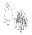
- FIG. 1is an isometric view of a squeeze bottle for sinus rinse including a main body, a soft, self-sealing nozzle having an aperture, and a collar attaching the nozzle to the main body.
- FIG. 2is a cross-section view taken along line 2 - 2 of FIG. 1 showing the main body defining a reservoir, a nozzle attached to the top of the main body by a collar, a check valve positioned between the nozzle and the top of the main body, and a tube connected from the bottom of the check valve extending into the reservoir of the main body.
- FIG. 3is an exploded view of the check valve with the collar and main body shown in FIG. 2 .
- FIGS. 4A and 4Bare exploded, top and bottom isometric views of the check valve similar to FIG. 3 .
- FIG. 5Ais an isometric, isolated view of the check valve, with the check valve including an upper portion and a lower portion, and together forming the air pressure channel, as well as the air inlet channel.
- FIG. 5Bis a cross-section view of the check valve in FIG. 5A as indicated by line 5 B- 5 B in FIG. 5A .
- FIG. 6is a cross-section view of the squeeze bottle depicted in FIG. 1 with a faceted nozzle, and shows the main body moving to an unsqueezed.
- FIG. 7is a cross-section view similar to that shown in FIG. 6 , with the main body being squeezed to force liquid up the tube through the check valve and out the nozzle into the user's nasal cavity, as well as increasing the pressure and possibly the internal volume of the nozzle.
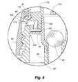
- FIG. 8is an enlarged cross-section view of FIG. 6 showing the reed valve in the opened position allowing air to pass into the main body through the air inlet passageway and the ball member in the valve seat preventing liquid or air from entering through the top of the check valve.
- FIG. 9is an enlarged cross-section view of FIG. 7 showing the reed valve in the closed position preventing air or liquid from passing through the air inlet passageway and the ball valve moved from the valve seat allowing liquid and air to pass from the reservoir of the main body through the check valve.
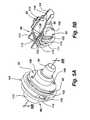
- FIG. 10Aan isometric view of an embodiment of a faceted nozzle.
- FIG. 10Bis a side elevation view of the nozzle illustrated in FIG. 10A .
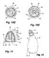
- FIG. 10Cis a top plan view of the nozzle illustrated in FIG. 10A .
- FIG. 10Dis a bottom plan view of the nozzle illustrated in FIG. 10A .
- FIG. 10Eis a bottom isometric view of the nozzle illustrated in FIG. 10A .
- FIG. 11is a cross-section view of the nozzle illustrated in FIG. 10A , viewed along line 11 - 11 in FIG. 10B .
- FIG. 12is an isometric view of a squeeze bottle for sinus rinse with a faceted nozzle.
- FIG. 1shows an implementation of a squeeze bottle 80 for a nasal cavity rinse.
- the squeeze bottle 80includes a main body 85 made of low-density polyethylene (LDPE).
- the main body 85defines a reservoir 87 in which a solution is placed for use in rinsing a user's nasal cavity.
- the top of the main bodyincludes an opening upon which is secured a soft, self-sealing nozzle 10 .
- the soft, self-sealing nozzle 10is secured to the top opening of the main body 85 by a collar 82 .
- the nozzle 10includes an aperture 62 which allows the solution inside the main body reservoir to exit the squeeze bottle 80 as desired by the user.
- the main body 85has a bottom portion 81 , which is relatively bulbous and fits well in a user's hand, and a top portion 83 , which narrows down significantly from the bulbous portion of the bottom portion 81 to a generally circular dimension having an outer maximum dimension approximately the same as the maximum dimension of the circular collar 82 which attaches the sealing nozzle 10 to the top opening of the main body 85 .
- the sealing nozzle 10is relatively dome-shaped with an aperture 62 positioned in the center of the top portion of the dome.
- the outlet aperture 62 of the nozzle 10allows the solution inside the reservoir 87 of the main body 85 to exit the squeeze bottle 80 as desired by the user.
- the sidewalls of the sealing nozzle 10extend down into the collar 82 to be secured by the collar 82 to the top opening of the main body 85 .
- the outer diameter of the sealing nozzle 10 at the bottom edgemay be significantly less than the outer diameter of the collar 82 holding the seal of the nozzle 10 to the main body 85 .
- the collar 82securing the nozzle 10 to the main body 85 , has a sloped outer surface angling from a smaller diameter to a larger diameter in the direction from top to bottom to form a frustum shape.
- An inner wall of the attachment collar 82may define threads 89 for engagement with the squeeze bottle 80 .
- a top portion of the collar 82forms a top edge 72 for coupling with the nozzle 10 .
- a bottom portion of the collar 82may have a vertical sidewall.
- the collar 82includes threads 89 formed on its interior surface for engaging with threads 88 of the main body 85 .
- FIG. 2a section is shown through the squeeze bottle 80 of FIG. 1 .
- a check valve 86is positioned between the nozzle 10 and the tube 90 extending into the reservoir 87 of the main body 85 .
- the delivery tube 90fluidly connects liquid within the reservoir 87 of the squeeze bottle 80 to the check valve 86 .
- the check valve 86allows fluid to be squeezed out of the main body 85 . It opens when the main body 85 is squeezed to allow fluid to leave the aperture 62 of the nozzle 10 after traveling up the tube 90 from the bottom of the reservoir 87 formed in the main body 85 .
- the check valve 86closes once the main body 85 is no longer squeezed and is returning to its original shape.
- the nozzle 10is held to the top portion 83 of the main body by the collar 82 .
- the lower rim 68 of the nozzlehas a flange or rim formed thereon which is retained against the flange 111 of the check valve, which in turn is retained against the top rim 91 of the main body 85 .
- top edge 72 of the collar 82which, once positioned over the nozzle 10 and the collar threads 89 , is threadedly engaged with the threads 88 on the outer perimeter of the top portion 83 of the main body, clamps the lower rim 68 at the bottom of the nozzle and the check valve 86 to the top of the main body 85 , and an airtight seal is formed between the nozzle 10 , check valve 86 , and top surface 91 of the main body.
- aircan flow through the void 93 formed between the threads 88 , 89 and into to the air inlet passage 110 , as described below.
- the threads 88 , 89may be removed along a portion of their length to create a “flat” spot to facilitate more direct and free airflow to the air inlet passage.
- the nozzlemay be faceted as illustrated in FIGS. 6 , 7 and 10 A- 12 in which a faceted nozzle 60 is shown. It will be understood that common reference element numbers provided above and herein below denote common features shared between the nozzle 10 and the faceted nozzle 60 .
- the nozzle 10 and the faceted nozzle 60 as shown in FIGS. 2 and 6respectively, have an elliptical cross-section shape having a tube extension 74 extending downwardly from the aperture 62 at the tip 70 of the nozzle, the tube extension 74 having a cylindrical shape.
- the tube extension 74may have a wall thickness of approximately 0.060 inches.
- a skirt wall 61extends downwardly from the aperture 62 at the tip of the nozzle and forms the outer elliptical cross-sectional shape of the nozzle.
- the skirt wall 61terminates in a lower rim 68 which extends radially outwardly from the skirt wall 61 and is part of the structure which is captured by the collar 82 as described above and again herein below.
- An annular bead 63is formed on the inner diameter of the lower end of the skirt wall 61 for receipt in an annular groove 114 formed on the outer periphery of the upper check valve housing 104 .
- the skirt wall 61may have a thickness of approximately 0.040 inches.
- the skirt wall 61may be smoothly curved in the generally conical shape as shown, or may be faceted or otherwise made up of regions having flat extensions or mixed flat and curved extensions. Also, a rib may be formed around the skirt wall just above the bottom edge to provide a protrusion for enhancing a user's gripping force on the nozzle if necessary.
- FIGS. 10A-10Eillustrate the faceted nozzle 60 in detail.
- the faceted nozzle 60may include a flange 68 at the terminal edge 24 of the skirt 61 . Additionally, the skirt 61 in this embodiment defines at a recessed groove 64 , which then expands outwards forming the flange 68 .
- FIG. 10Aillustrates an isometric view of the faceted nozzle 60
- FIG. 10Billustrates a side elevation view of the faceted nozzle 60
- FIG. 10Cis a top plan view of the faceted nozzle 60
- FIG. 10Dis a bottom plan view of the faceted nozzle 60
- FIG. 10Eis a bottom isometric view of the faceted nozzle 60 .
- FIG. 10Aillustrates an isometric view of the faceted nozzle 60
- FIG. 10Billustrates a side elevation view of the faceted nozzle 60
- FIG. 10Cis a top plan view of the faceted nozzle 60
- FIG. 10Dis a bottom plan view
- FIG. 11is a section view of the faceted nozzle 60 of FIG. 10B taken along line 11 - 11 .
- the faceted nozzle 60includes an outlet aperture 62 located at the apex of the tip 70 . Extending outward and downward from the outlet aperture 62 is the skirt 61 .
- the skirt 61includes steps 66 a - 66 e or facets along its outer surface. The steps 66 a - 66 e also act to provide a seal against a nostril wall when the faceted nozzle 60 is inserted into a user's nasal cavity.
- the skirt 61 of the faceted nozzle 60acts to form a seal with the user's nostril when the faceted nozzle 60 is attached to the reservoir body 80 .
- the skirt 61includes steps 66 a - 66 e , which create ridges the outer surface of the skirt 61 .
- the steps 66 a - 66 emay be approximately the same height; however each step 66 a - 66 e may have a different average or center diameter.
- each step 66 a - 66 eincreases the overall outer diameter of the skirt 61 and the faceted nozzle 60 maintains a generally rounded shape.
- the first step 66 ahas a smaller average diameter than the second step 66 b , and so on.
- the steps 66 a - 66 emay have different widths, such that the first step 66 a may cover a greater portion of the outer surface of the skirt 61 than the second step 66 b.
- the steps 66 a - 66 emay be a series of stacked conical frustums having different outer wall angles.
- Each step 66 a - 66 eis sloped at a predetermined angled and the outer wall has a larger diameter at the bottom edge of the steps 66 a - 66 e than at the top edge of each step 66 a - 66 e .
- each step 66 a - 66 edecreases in diameter from the bottom edge to the top edge.
- each step 66 a - 66 emay have a different average diameter than the preceding step 66 a - 66 e .
- each step 66 a - 66 emay have a different outer wall angle than the previous step 66 a - 66 e .
- the configuration of stacked frustum sections on top of one anothermay include ridges between each of the steps 66 a - 66 e at the point of transition, from one step 66 a - 66 e to the next. This gives the skirt 61 a faceted appearance and feel.
- the tip 70may be inserted into a user's nostril and one of the steps 66 a - 66 e creates a seal between the faceted nozzle 60 and the nostril walls (see FIG. 7 ).
- the particular step 66 a - 66 e that engages the user's nostrildepends upon the size of the user's nostril. For example, the larger the user's nostril the lower the step 66 a - 66 e may be that engages the nostril wall.
- the steps 66 a - 66 ecreate a better seal than a purely rounded nozzle, as the steps 66 a - 66 e better conform to the nostril wall—the nostril wall is not purely oval-shaped or conical-shaped—and the steps 66 a - 66 e better mimic the inner surface of the nostril wall. It should be noted that although five steps 66 a - 66 e have been illustrated, any number of steps 66 a - 66 e may be included. The number of steps 66 a - 66 e may be altered to create a smoother or rougher skirt 61 . For example, depending on the desired sealing level the number of steps 66 a - 66 e may be increased or decreased.
- the skirt 61 illustrated in FIGS. 10A-11terminates at the recessed groove 64 , which has a smaller diameter than the fifth step 66 e , such that the diameter of the faceted nozzle 60 decreases after the fifth step 66 e .
- the recessed groove 64then expands into the flange 68 , which has a larger diameter than the fifth step 66 e .
- the groove 64reduces the diameter of the faceted nozzle 60 at the end of the skirt 61 .
- the groove 64may be used to better attach the faceted nozzle 60 to a nasal rinse reservoir by providing a connection location, for example, for the collar 82 described below. In other embodiments the groove 64 may be used to reduce the material used to create the faceted nozzle 60 .
- the flange 68may form the largest diameter of the faceted nozzle 60 and may be larger than any of the steps 66 a - 66 e .
- the recessed groove 64 and the flange 68may be used to secure the faceted nozzle 60 to a nasal rinse squeeze bottle, which will be discussed in more detail below with respect to FIGS. 2 and 6 .
- the faceted nozzle 60includes an inner collar 74 or conduit extending downwards from the tip 70 , creating the outlet aperture 62 .
- the inner collar 74may extend to the tip 70 and be substantially the same diameter throughout its entire length.
- the inner collar 74extends downward and is surrounded by the skirt 61 .
- the distal end 76 of the inner collar 74terminates before extending as far as the outer groove 64 or the flange 68 .
- the inner collar 74may extend the entire length of the faceted nozzle 60 .
- the inner collar 74may have a wall thickness of approximately 0.060 inches.
- the inner wall 79 of the skirt 61surrounds the inner collar 74 and the inner collar 74 is separated from the inner wall 79 , such that the inner collar 74 and the inner wall 79 may not contact each other.
- the space between the inner collar 74 and the inner wall 79 of the skirt 61creates a void 78 or empty area when the nozzle is connected to the squeeze bottle reservoir.
- FIGS. 2 and 6illustrate the faceted nozzle 60 attached to a nasal rinse squeeze bottle 80 by an attachment collar 82 .
- the attachment collar 82extends over a portion of the faceted nozzle 60 , to better secure the faceted nozzle 60 to the squeeze bottle 80 .
- the outer diameter of the faceted nozzle 60 at the flange 68may be less than the outer diameter of the attachment collar 82 holding the faceted nozzle 60 to the squeeze bottle 80 .
- a top shelf or shoulder 87 of the attachment collar 82sits on top of the flange 68 and rests on the upper surface 72 of the flange 68 . Additionally, the shoulder 87 extends at least partially into the recessed groove 64 on the faceted nozzle 60 .
- the attachment collar 82helps anchor the faceted nozzle 60 as well as create an airtight seal when the faceted nozzle 60 is held in place against the squeeze bottle 80 .
- flange 68is retained against a collar of a check valve 86 (further described below), which in turn is retained against a top rim 91 of the main body 85 of the squeeze bottle 80 .
- a check valve 86(further described below), which in turn is retained against a top rim 91 of the main body 85 of the squeeze bottle 80 .
- Each of theseis retained in position by the shoulder 87 of the attachment collar 82 , which once positioned over the faceted nozzle 60 and threadedly engaged with the threads 88 on the outer perimeter of the top portion 83 of the main body 85 , clamps the flange 68 of the faceted nozzle 60 and the check valve 86 to the top of the squeeze bottle 80 .
- the faceted nozzle 60is also attached to the check valve 86 by the inner collar 74 .
- the valve assembly 86includes an upwardly extending rim 112 that connects with the inner collar 74 , fluidly connecting the inside of the squeeze bottle 80 with the outlet aperture 62 of the faceted nozzle 60 .
- the inner collar 74may be received partially within the extending rim 112 .
- the extending rim 112may be received within the inner collar 74 .
- an o-ring or other sealing mechanismmay be inserted within the rim 112 to fit around the inner collar 74 in order to better seal the connection between the extending rim 112 and the inner collar 74 .
- annular rim 112 of the check valveforms a recess above the flange 111 , and the annular recess receives the tube extension 74 of the nozzle to help anchor the faceted nozzle 60 as well as create an airtight seal when the faceted nozzle 60 is held in place against the check valve 86 and the top rim 91 of the main body by the collar 82 .
- the annular bead 63 or rim at a bottom portion of the skirt wall 61is received in the annular groove 114 formed in the outer perimeter of the upper check valve 104 as described above.
- a flange or lower rim 68extends radially outwardly from the base of the skirt wall 61 on the nozzle and is the bearing surface against which the collar 82 engages to clamp the rim 68 with the flange 111 on the upper check valve housing 92 against the top rim 91 of the main body 80 to create an airtight seal between the faceted nozzle 60 , check valve 86 , and top surface 91 of the main body.
- FIG. 2illustrates a cross-section view of the nozzle secured to the squeeze bottle 80 and FIG. 3 illustrates an exploded view of the attachment collar 82 and the check valve 86 .
- FIG. 4Ais an enlarged, left-side, exploded isometric view of the valve housing illustrated in FIG. 3 .
- FIG. 4Bis an enlarged, right-side, exploded isometric view of the valve housing illustrated in FIG. 3 .
- FIG. 5Ais an isometric view of the valve housing removed from the squeeze bottle.
- FIG. 5Bis a cross-section view of the valve housing viewed along line 5 B- 5 B in FIG. 5A . Referring to FIGS.
- the check valve 86is positioned in fluid communication between the outlet aperture 62 in the faceted nozzle 60 and a delivery tube 90 extending from the bottom of the check valve 86 into the reservoir formed in the squeeze bottle 80 .
- the check valve 86has an upper portion 104 and a lower portion 92 , as shown in FIG. 5B , and defines a contained space forming a cavity 95 .
- the upper portion 104 and the lower portion 92 of the check valve 86may be secured together via attachment pegs 108 extending from a bottom surface of the upper portion 104 .
- the attachment pegs 108are received within receiving apertures 98 on the lower portion 92 of the housing.
- the attachment pegs 108may also attach to a reed valve 102 through securing apertures 107 disposed on the reed valve 102 at the terminal ends of the semi-circular shaped reed valve 102 .
- the upper housing 104 , the reed valve 102 , and the lower housing 92are secured together to form the check valve 86 as illustrated in FIG. 5A .
- An annular extension 94extends from the bottom of the lower check valve housing 92 for receiving the top end of the liquid delivery tube 90 in a friction-fit engagement.
- the end of the annular extension 94may be chamfered to help guide the liquid delivery tube 90 onto the annular extension 94 .
- the lower check valve housing 92includes a circular conical wall 100 protruding from a top end that is received in a recess formed by the upper check valve housing 104 when the housing portions are positioned together.
- the ball member 84is received within the cavity 95 defined within an interior the assembled check valve 86 .
- the delivery tube 90is attached to an annular extension 94 depending from the lower check valve housing 92 .
- a cavity 95is formed within the lower portion 92 , and a valve seat 116 is formed near the bottom of the cavity 95 by a circular conical wall 100 , and a retention structure 113 is formed at the top which allows fluid through but does not allow the ball member 84 through.
- the fluidpushes the ball member 84 out of the valve seat 116 and up against the retention structure 113 , with the liquid flowing around the retaining structure 113 and out the aperture of the nozzle 62 .
- the main body 85When the main body 85 is not being squeezed, it is resilient and returns to its original shape which relieves the pressure of the fluid on the ball member 84 , which allows the ball member 84 to move back down into the valve seat 116 and keep any liquid from flowing back into the reservoir 87 in the main body 85 . This is beneficial to keep any fluid that may come back into the tip from the user's nostrils or sinus' from getting back into the liquid positioned in the main body 85 .
- the ball 84may move freely within the cavity 95 .
- the retention structure 113is at the top of the cavity 95 .
- the retention structure 113which may be in the shape of a cross extending across the fluid passageway formed through the center of the check valve 86 , prevents the ball 84 from moving out of the cavity 95 into the upper portion 104 of the check valve 86 .
- the cavity 95 and the retention structure 113are in fluid communication with the inner collar 74 above and the liquid delivery tube 90 extending below into the squeeze bottle 80 . That is, the recess 95 acts as a fluid conduit, connecting the delivery tube 90 and the extending rim 112 .
- the sidewalls of the recess 95are generally cylindrical, and taper at their bottom ends to form a valve seat 116 .
- the upper check valve housing 104defines a vertical rim 112 protruding from its top end, which receives a tubular extension 74 depending from the aperture 62 formed at the tip 70 of the faceted nozzle 60 .
- the inner diameter of the vertical rim 112 and the outer diameter of the tubular extension 74may have substantially similar dimensions to provide a sealing fit or a friction fit engagement.
- the extending rim 112is fluidly connected to the outlet aperture 62 when the faceted nozzle 60 is connected to the squeeze bottle 80 .
- the cavity 95acts as a fluid conduit, connecting the delivery tube 90 and the extending rim 112 . Additionally, the sidewalls of the cavity 95 are generally cylindrical, and taper at their bottom ends to form the valve seat 116 .
- the check valve 86also defines a passageway 118 creating communication for air or liquid from the reservoir 87 of the squeeze bottle 80 through the passageway 118 and into the void space 78 between the faceted nozzle 60 and the check valve 86 .
- the air pressure passageway 118is formed to extend through the lower check valve housing 92 and the upper check valve housing 104 , and a lower opening into the squeeze bottle 80 and an upper opening into the void space 78 .
- the air pressure passageway 118allows fluid and/or gaseous communication between the reservoir 87 of the main body 85 and the void space 78 formed between the tube extension 74 and the skirt wall 61 in the faceted nozzle 60 .
- the void space 78may be annular around the tube extension 74 , or may not be continuous.
- an air inlet passageway 110 and a reed valve structure 102is also formed in the check valve 86 which allows air to be drawn into the reservoir 87 in the main body 85 when the main body is not being squeezed and is returning from a squeezed to an unsqueezed configuration, and thus draws air in through the air inlet passageway 110 .
- the air inlet passageway 110is provided in a discrete location of the check valve 86 housing in relation to the air pressure passageway 118 .
- the air inlet passageway 110 and the air pressure passageway 118are arranged at opposite ends of the annularly shaped check valve 86 , e.g., the two are separated by approximately 180°.
- the reed valve structure 102resiliently seals the air inlet passageway 110 , as described below.
- the air inlet passageway 110is shown extending from an outer portion of the upper check valve housing 104 .
- the outer opening 105 of the air inlet passageway 110may have an area of approximately 0.01 inches squared, is generally oval in shape and extends radially or laterally into the upper check valve housing 104 . However, it may be differently shaped as desired.
- the inflation port 106 of the air inlet passageway 110extends axially in the upper check valve housing 104 and forms a continuous passage with the radially extending outer opening 105 .
- the check valve housinghas an outwardly extending flange 111 around about its middle which is the portion of the check valve housing that is trapped by the collar 82 against the top rim 91 of the main body.
- the inflation port 110is formed in the check valve 86 that communicates between the reservoir 87 of the squeeze bottle 80 and the atmosphere.
- the threading 89 of the attachment collar 82 and the threading 88 of the squeeze bottle 80are designed to create a void 93 to allow an air gap between adjacent threads.
- aircan travel in a spiral path between the threads 88 , 89 to enter the inflation port 110 and fill the reservoir in the squeeze bottle 80 after fluid has been dispensed, thus preventing the check valve 86 from creating a vacuum.
- the valve on the air inlet passageway 110may be a reed valve 102 , such as a flapper valve, and when the main body 85 is being squeezed to force fluid out of the nozzle, the flapper valve covers the inflation port 106 of the air inlet passageway 110 and thus blocks the flow of air out of the air inlet passageway 110 , which helps force the fluid up the delivery tube 90 .
- the reed valve 102is shown in FIG. 5A as extending in a semi-circular orientation inside of a slot formed below the flange 111 extending from the check valve 86 .
- the lower bounds of the semi-circular slotare formed by the guard 96 mentioned above with respect to FIGS. 2 and 6 .
- the reed valve 102is a thin, flexible piece of FDA grade silicone rubber having a thickness of approximately 0.015 inches thick. Again, the guard 96 helps keep the reed valve 102 from opening too far as well as protects the reed valve 102 from interference by any particulates that may find their way into the liquid received in the reservoir 87 of the main body.
- the reed valve 102is disposed between the upper portion 104 and lower portion 92 of the check valve 86 .
- the reed valve 102covers the air inlet port 110 to selectively connect the inflation port 106 to the reservoir 87 of the squeeze bottle 80 .
- the inflation port 106is the internal opening of the air inlet port 110 .
- the reed valve 102may be a flat flexible semi-circular plate structure which is attached on the pegs 108 between the upper portion 104 and the lower portion 92 at its ends in a cantilever fashion.
- This reed valve 102is typically in a closed position in which it seals against the inflation port 106 and opens under the negative pressure of the squeeze bottle 80 when moving from a squeezed to the un-squeezed position.
- the reed valve 102 materialmay be FDA grade silicone rubber and may be approximately 0.015 inches thick.
- a guard plate 96extends radially outwardly from the outer surface of the lower portion 92 of the check valve 86 in order to protect the reed valve 102 from interference by particulates and also to keep the reed valve 102 from opening too far.
- a gap 10is formed between the end of the guard 96 and the inner wall of the top portion of the main body 85 to allow air or liquid to flow thereby towards the reed valve 102 and the inflation port 106 of the air inlet passageway 110 .
- the gap 10allows air to flow from the void space 93 in the threaded interconnection into the air inlet passageway 110 , past the reed valve 102 and through the gap 10 into the reservoir 87 of the main body 85 .
- the skirt 61may deform based on contact with the edges of the nostril.
- the fluidtravels via the delivery tube 90 and pushes the ball 84 out of the valve seat 116 up against the retention structure 113 .
- Liquidthen flows around the ball 84 and the retention structure 113 and out the outlet aperture 62 of the faceted nozzle 60 .
- the liquidcannot escape through the inflation port 106 because the reed valve 102 is closed.
- the passageway 118 formed through the check valve 86allows air or liquid pressure to be applied to the skirt 61 walls inside the void space 78 in the faceted nozzle 60 , thus creating an outward pressure on the skirt walls 61 of the faceted nozzle 60 and enhancing the fit of the faceted nozzle 60 within the nostril of the user.
- itis liquid or air flowing into the void space 78 in the nozzle, that liquid or air pressure helps create a firm but forming fit of the faceted nozzle 60 against the user's nostril during the nasal cavity process.
- Pressure in the void space 78also causes the skirt 61 and/or the tubular extension 74 to force liquid out of the nozzle aperture 62 .
- the resilient sidewallsare biased back into their original position, which creates a vacuum or negative pressure inside the cavity 95 , allowing the ball 84 to move back down into the valve seat 116 and prevents fluid from flowing back into the reservoir 87 .
- Thisis beneficial as it prevents fluid that may come back into the outlet aperture 62 from the user's nostrils or sinus from draining into the reservoir in the squeeze bottle 80 .
- the air inlet passageway 110 in combination with the reed valve 102substantially prevent a vacuum from occurring within the squeeze bottle 80 after squeezing. That is, after squeezing, the squeeze bottle 80 reservoir 87 may be under negative pressure or vacuum pressure, and the reed valve 102 opens based on this pressure. When the reed valve 102 opens, the air inlet passageway 110 connects to the reservoir 87 , as the inflation port 106 becomes unblocked, allowing air to enter.
- the air flowing into the air inlet passageway 110comes through the void space 93 in the thread structure 88 , into the outer opening 105 of the inlet passageway 110 , through the inflation port 106 of the air inlet passageway 110 , and past the reed valve 102 and the gap 10 formed between the end of the guard 96 and the inner wall of the top portion of the main body 85 .
- the airthen flows down into the reservoir 87 in the main body 85 until the main body 85 is back to its original configuration.
- the reed valve 102resiliently moves to its closed position and closes over the inflation port 106 of the air inlet passageway 110 and the bottle 80 is ready for the next application. This helps to prevent the squeeze bottle 80 from remaining in a compressed shape after the user has stopped squeezing the bottle 80 .
- FIG. 7The compression of the main body 85 to force liquid out of the reservoir 87 therein is shown in FIG. 7 and the extension of the main body 85 from the squeezed configuration to the unsqueezed configuration with the associated liquid and air flows are shown in FIG. 6 .
- the two valves, the reed valve 102 and the check valve 86operate together to provide improved protection against the drawing of the nasal wash from back-flowing into the bottle 80 .
- the check valve 86moves to the closed position (under vacuum pressure) when the squeeze bottle 80 is moving to the uncompressed configuration. This provides a physical block to the passage of any used nasal wash flowing back into the delivery tube 90 and into the bottle 80 .
- the reed valve 102acts as a vacuum breaker to allow air into the bottle 80 through a different passage than the check valve 86 , which reduces the vacuum pressure caused by the expansion of the bottle 80 sidewalls that tries to draw fluid in through the check valve 86 .
- references herein to “up” or “top”, “bottom” or “down”, “lateral” or “side”, and “horizontal” and “vertical”, as well as any other relative position descriptorare given by way of example for the particular embodiment described and not as a requirement or limitation of the squeeze bottle 80 or the apparatus and method for assembling the squeeze bottle 80 .
- Reference herein to “is”, “are”, “should”, “would”, or other words implying a directive or positive requirementare intended to be inclusive of the permissive use, such as “may”, “might”, “could” unless specifically indicated otherwise.
Landscapes
- Engineering & Computer Science (AREA)
- Ceramic Engineering (AREA)
- Mechanical Engineering (AREA)
- Closures For Containers (AREA)
- Infusion, Injection, And Reservoir Apparatuses (AREA)
Abstract
Description
Claims (24)
Priority Applications (1)
| Application Number | Priority Date | Filing Date | Title |
|---|---|---|---|
| US12/970,415US8991660B2 (en) | 2009-12-16 | 2010-12-16 | Squeeze bottle for sinus cavity rinse |
Applications Claiming Priority (7)
| Application Number | Priority Date | Filing Date | Title |
|---|---|---|---|
| US28701609P | 2009-12-16 | 2009-12-16 | |
| US29/352,093USD653953S1 (en) | 2009-12-16 | 2009-12-16 | Squeeze bottle |
| US29/352,100USD634630S1 (en) | 2009-12-16 | 2009-12-16 | Nozzle |
| US29/352,101USD634631S1 (en) | 2009-12-16 | 2009-12-16 | Nozzle and collar |
| US29/364,669USD676125S1 (en) | 2010-06-25 | 2010-06-25 | Faceted nasal seal with bottom rim |
| US36937810P | 2010-07-30 | 2010-07-30 | |
| US12/970,415US8991660B2 (en) | 2009-12-16 | 2010-12-16 | Squeeze bottle for sinus cavity rinse |
Related Parent Applications (1)
| Application Number | Title | Priority Date | Filing Date |
|---|---|---|---|
| US29/352,093Continuation-In-PartUSD653953S1 (en) | 2009-12-16 | 2009-12-16 | Squeeze bottle |
Publications (2)
| Publication Number | Publication Date |
|---|---|
| US20110139826A1 US20110139826A1 (en) | 2011-06-16 |
| US8991660B2true US8991660B2 (en) | 2015-03-31 |
Family
ID=44141791
Family Applications (1)
| Application Number | Title | Priority Date | Filing Date |
|---|---|---|---|
| US12/970,415Expired - Fee RelatedUS8991660B2 (en) | 2009-12-16 | 2010-12-16 | Squeeze bottle for sinus cavity rinse |
Country Status (1)
| Country | Link |
|---|---|
| US (1) | US8991660B2 (en) |
Cited By (9)
| Publication number | Priority date | Publication date | Assignee | Title |
|---|---|---|---|---|
| US20150014356A1 (en)* | 2012-02-23 | 2015-01-15 | Bostik S.A. | Dispenser packaging for viscous liquid comprising large particles |
| USD753811S1 (en)* | 2014-02-25 | 2016-04-12 | Hapella Oy | Respiratory device |
| USD768503S1 (en)* | 2014-03-28 | 2016-10-11 | The Procter & Gamble Company | Foam dispenser |
| USD855796S1 (en)* | 2015-07-31 | 2019-08-06 | Bedo Solutions, Llc | Rounded eye-drop bottle reservoir |
| USD897525S1 (en)* | 2019-03-31 | 2020-09-29 | Ningbo Albert Novosino Co., Ltd | Nasal aspirator |
| US11317933B1 (en)* | 2017-10-05 | 2022-05-03 | Nathedra G. White | Nasal cleaning tool |
| US20230032289A1 (en)* | 2021-07-28 | 2023-02-02 | Duco Llc | Fluid dispensing apparatus for irrigating a body cavity |
| US20230310818A1 (en)* | 2020-08-28 | 2023-10-05 | The Regents Of The University Of California | Device and method for administering liquid to the ear canal |
| US12220548B2 (en)* | 2016-08-01 | 2025-02-11 | Giorgio Mezzoli | Dispenser |
Families Citing this family (93)
| Publication number | Priority date | Publication date | Assignee | Title |
|---|---|---|---|---|
| US20070203439A1 (en) | 2006-02-24 | 2007-08-30 | Water Pik, Inc. | Water jet unit and handle |
| US7670141B2 (en) | 2006-07-07 | 2010-03-02 | Water Pik, Inc. | Oral irrigator |
| US20100239998A1 (en)* | 2009-03-20 | 2010-09-23 | Water Pik, Inc. | Oral irrigator appliance with radiant energy delivery for bactericidal effect |
| US10258442B2 (en) | 2009-03-20 | 2019-04-16 | Water Pik, Inc. | Oral irrigator appliance with radiant energy delivery for bactericidal effect |
| US9061096B2 (en) | 2009-12-16 | 2015-06-23 | Water Pik, Inc. | Powered irrigator for sinus cavity rinse |
| US8486029B2 (en)* | 2009-12-16 | 2013-07-16 | Water Pik, Inc. | Pot for sinus cavity rinse |
| USD676125S1 (en) | 2010-06-25 | 2013-02-12 | Water Pik, Inc. | Faceted nasal seal with bottom rim |
| US8888752B2 (en)* | 2009-12-16 | 2014-11-18 | Water Pik, Inc. | Bottle for sinus cavity rinse |
| USD676126S1 (en) | 2010-06-25 | 2013-02-12 | Water Pik, Inc. | Faceted nasal seal |
| WO2011079301A1 (en)* | 2009-12-24 | 2011-06-30 | Geraghty, Erin | Container cap |
| US8409152B2 (en) | 2010-06-25 | 2013-04-02 | Water Pik, Inc. | Faceted nasal seal |
| USD670373S1 (en)* | 2010-12-16 | 2012-11-06 | Water Pik, Inc. | Powered irrigator for sinus cavity rinse |
| ES2935418T3 (en) | 2011-08-10 | 2023-03-06 | Fisher & Paykel Healthcare Ltd | Conduit connector for a patient breathing device |
| USD707350S1 (en) | 2012-10-11 | 2014-06-17 | Water Pik, Inc. | Handheld water flosser |
| US10105201B2 (en) | 2012-10-11 | 2018-10-23 | Water Pik, Inc. | Interdental cleaner using water supply |
| USD717427S1 (en) | 2013-03-14 | 2014-11-11 | Water Pik, Inc. | Handle for water flosser |
| USD725770S1 (en) | 2013-03-14 | 2015-03-31 | Water Pik, Inc. | Reservoir for water flosser |
| USD788907S1 (en) | 2013-03-14 | 2017-06-06 | Water Pik, Inc. | Water flosser base unit with reservoir lid |
| USD714929S1 (en) | 2013-03-14 | 2014-10-07 | Water Pik, Inc. | Base for water flosser |
| US9642677B2 (en) | 2013-03-14 | 2017-05-09 | Water Pik, Inc. | Oral irrigator with massage mode |
| USD737951S1 (en)* | 2013-11-26 | 2015-09-01 | Church & Dwight Co., Inc. | Nozzle |
| US9980793B2 (en) | 2013-11-27 | 2018-05-29 | Water Pik, Inc. | Oral hygiene system |
| KR101824347B1 (en) | 2013-11-27 | 2018-01-31 | 워어터 피이크, 인코포레이티드 | Oral irrigator with slide pause switch |
| CN203693808U (en) | 2013-12-12 | 2014-07-09 | 洁碧有限公司 | Dental water sprayer |
| CN103721882B (en)* | 2013-12-13 | 2016-08-17 | 中山市美捷时包装制品有限公司 | A kind of aerosol apparatus of belt switch |
| USD777903S1 (en)* | 2014-01-28 | 2017-01-31 | Splash Medical Devices, LLC | Nasal-irrigation fitting |
| USD743019S1 (en)* | 2014-01-28 | 2015-11-10 | Joseph P. Schultz | Nasal-irrigation fitting |
| USD743020S1 (en)* | 2014-05-30 | 2015-11-10 | Ketan C. Mehta | Nasal rinse tip |
| AU359661S (en)* | 2014-07-03 | 2014-12-18 | Reckitt Benckiser Brands Ltd | Cap |
| FR3027808B1 (en)* | 2014-11-04 | 2021-01-15 | Aptar France Sas | NASAL DISTRIBUTION HEAD AND FLUID PRODUCT DISTRIBUTION DEVICE INCLUDING SUCH A HEAD. |
| CN205586102U (en)* | 2014-12-01 | 2016-09-21 | 洁碧有限公司 | Waterproof wireless oral cavity flusher |
| USD772396S1 (en) | 2014-12-01 | 2016-11-22 | Water Pik, Inc. | Handheld oral irrigator |
| USD772397S1 (en) | 2014-12-01 | 2016-11-22 | Water Pik, Inc. | Oral irrigator with a charging device |
| US11446462B2 (en) | 2015-03-31 | 2022-09-20 | Fisher & Paykel Healthcare Limited | Apparatus for use in a respiratory support system |
| USD803388S1 (en)* | 2015-07-10 | 2017-11-21 | Brian M. Miller | Collapsible nasal irrigation container |
| WO2017037660A1 (en) | 2015-09-04 | 2017-03-09 | Fisher & Paykel Healthcare Limited | Connectors for conduits |
| USD780908S1 (en) | 2015-11-03 | 2017-03-07 | Water Pik, Inc. | Handheld oral irrigator |
| USD822196S1 (en) | 2016-01-14 | 2018-07-03 | Water Pik, Inc. | Oral irrigator |
| USD802747S1 (en) | 2016-07-19 | 2017-11-14 | Water Pik, Inc. | Reservoir for oral irrigator |
| USD819956S1 (en) | 2016-01-25 | 2018-06-12 | Water Pik, Inc. | Kit bag |
| USD782656S1 (en) | 2016-01-25 | 2017-03-28 | Water Pik, Inc. | Oral irrigator |
| US10835356B2 (en) | 2016-01-25 | 2020-11-17 | Water Pik, Inc. | Swivel assembly for oral irrigator handle |
| KR102072661B1 (en) | 2016-01-25 | 2020-02-03 | 워터 피크 인코포레이티드 | Mouthwashes with Reduced Shape Factors |
| USD786422S1 (en) | 2016-01-25 | 2017-05-09 | Water Pik, Inc. | Oral irrigator |
| USD794773S1 (en) | 2016-07-19 | 2017-08-15 | Water Pik, Inc. | Oral irrigator |
| USD796028S1 (en) | 2016-07-19 | 2017-08-29 | Water Pik, Inc. | Oral irrigator |
| USD783809S1 (en) | 2016-01-25 | 2017-04-11 | Water Pik, Inc. | Oral irrigator handle |
| USD804018S1 (en) | 2016-07-19 | 2017-11-28 | Water Pik, Inc. | Base for an oral irrigator |
| USD804016S1 (en) | 2016-02-05 | 2017-11-28 | Water Pik, Inc. | Handheld oral irrigator |
| USD809650S1 (en) | 2016-02-22 | 2018-02-06 | Water Pik, Inc. | Oral irrigator |
| USD783810S1 (en) | 2016-02-22 | 2017-04-11 | Water Pik, Inc. | Handle for an oral irrigator |
| USD782657S1 (en) | 2016-03-02 | 2017-03-28 | Water Pik, Inc. | Oral irrigator handle |
| USD802119S1 (en) | 2016-03-02 | 2017-11-07 | Water Pik, Inc. | Oral irrigator |
| CA3016031C (en) | 2016-03-02 | 2020-07-07 | Water Pik, Inc. | Actuation assembly for an oral irrigator |
| USD809656S1 (en) | 2016-06-10 | 2018-02-06 | Fisher & Paykel Healthcare Limited | Connector for a breathing circuit |
| USD807822S1 (en) | 2016-07-19 | 2018-01-16 | Water Pik, Inc. | Power supply cartridge |
| USD809651S1 (en) | 2016-07-19 | 2018-02-06 | Water Pik, Inc. | Combination base and reservoir for an oral irrigator |
| USD852949S1 (en)* | 2016-09-22 | 2019-07-02 | Fisher & Paykel Healthcare Limited | Connector for a nasal cannula assembly |
| USD832420S1 (en) | 2016-12-15 | 2018-10-30 | Water Pik, Inc. | Oral irrigator base |
| USD832418S1 (en) | 2016-12-15 | 2018-10-30 | Water Pik, Inc. | Oral irrigator base |
| USD840023S1 (en) | 2016-12-15 | 2019-02-05 | Water Pik, Inc. | Oral irrigator reservoir |
| USD867579S1 (en) | 2016-12-15 | 2019-11-19 | Water Pik, Inc. | Oral irrigator unit |
| USD825741S1 (en) | 2016-12-15 | 2018-08-14 | Water Pik, Inc. | Oral irrigator handle |
| USD833600S1 (en) | 2016-12-15 | 2018-11-13 | Water Pik, Inc. | Oral irrigator reservoir |
| USD834180S1 (en) | 2016-12-15 | 2018-11-20 | Water Pik, Inc. | Oral irrigator base |
| CN110267623B (en) | 2016-12-15 | 2022-03-29 | 洁碧有限公司 | Pause valve and swivel assembly for oral irrigator handle |
| USD839409S1 (en) | 2016-12-15 | 2019-01-29 | Water Pik, Inc. | Oral irrigator unit |
| USD829886S1 (en) | 2016-12-15 | 2018-10-02 | Water Pik, Inc. | Oral irrigator base |
| KR20230131961A (en) | 2016-12-15 | 2023-09-14 | 워어터 피이크, 인코포레이티드 | Control assembly for oral irrigator |
| USD822826S1 (en) | 2016-12-15 | 2018-07-10 | Water Pik, Inc. | Oral irrigator base |
| USD822825S1 (en) | 2016-12-15 | 2018-07-10 | Water Pik, Inc. | Oral irrigator unit |
| USD832419S1 (en) | 2016-12-15 | 2018-10-30 | Water Pik, Inc. | Oral irrigator unit |
| USD833000S1 (en) | 2016-12-15 | 2018-11-06 | Water Pik, Inc. | Oral irrigator unit |
| USD840022S1 (en) | 2016-12-15 | 2019-02-05 | Water Pik, Inc. | Oral irrigator handle |
| USD833601S1 (en) | 2017-02-06 | 2018-11-13 | Water Pik, Inc. | Oral irrigator |
| USD829887S1 (en) | 2017-02-06 | 2018-10-02 | Water Pik, Inc. | Oral irrigator reservoir |
| USD833602S1 (en) | 2017-02-06 | 2018-11-13 | Water Pik, Inc. | Oral irrigator base |
| USD864918S1 (en)* | 2017-05-08 | 2019-10-29 | Dadong Liu | Earphone |
| USD868243S1 (en) | 2018-03-16 | 2019-11-26 | Water Pik, Inc. | Oral irrigator tip |
| USD877324S1 (en) | 2018-05-17 | 2020-03-03 | Water Pik, Inc. | Oral irrigator handle |
| USD942586S1 (en)* | 2018-11-27 | 2022-02-01 | Church & Dwight Co., Inc. | Front band on a spray nozzle |
| USD889636S1 (en) | 2019-02-22 | 2020-07-07 | Water Pik, Inc. | Water flosser |
| USD888936S1 (en) | 2019-02-22 | 2020-06-30 | Water Pik, Inc. | Cordless water flosser |
| USD1006981S1 (en) | 2019-09-06 | 2023-12-05 | Fisher & Paykel Healthcare Limited | Breathing conduit |
| USD948027S1 (en) | 2019-09-10 | 2022-04-05 | Fisher & Paykel Healthcare Limited | Connector for a breathing conduit |
| USD940861S1 (en) | 2020-03-03 | 2022-01-11 | Fisher & Paykel Healthcare Limited | Connector for a respiratory system conduit |
| USD1058539S1 (en)* | 2020-03-23 | 2025-01-21 | Flare Audio Technologies Limited | Earphone |
| USD966498S1 (en) | 2020-09-15 | 2022-10-11 | Water Pik, Inc. | Oral irrigator |
| USD974551S1 (en) | 2020-12-09 | 2023-01-03 | Fisher & Paykel Healthcare Limited | Connector assembly and connector |
| USD1016274S1 (en) | 2021-02-16 | 2024-02-27 | Water Pik, Inc. | Oral irrigator |
| USD1073919S1 (en) | 2021-05-17 | 2025-05-06 | Fisher & Paykel Healthcare Limited | Respiratory system conduit with connector |
| USD995758S1 (en) | 2021-06-11 | 2023-08-15 | Fisher & Paykel Healthcare Limited | Tube assembly and connector |
| USD1013858S1 (en)* | 2021-08-23 | 2024-02-06 | Nina D. Farzin | Nasal aspirator |
Citations (117)
| Publication number | Priority date | Publication date | Assignee | Title |
|---|---|---|---|---|
| US465559A (en) | 1891-12-22 | Oil-can | ||
| US2115959A (en) | 1936-02-03 | 1938-05-03 | Beverly Products Corp | Combined dropper and atomizer |
| US2571921A (en) | 1948-06-02 | 1951-10-16 | Morris Robert | Atomizer of single piece construction |
| US2578864A (en) | 1948-12-01 | 1951-12-18 | Earl S Tupper | Seal for flexible containers |
| US2722458A (en) | 1952-06-02 | 1955-11-01 | Spraying Systems Co | Nozzles of flat spray type |
| US2811283A (en) | 1956-04-06 | 1957-10-29 | John D Bowen | Squeeze-to-use fluid dispensers |
| US2987261A (en) | 1958-10-09 | 1961-06-06 | Robert E Mccuiston | Atomizers |
| GB881807A (en) | 1957-10-22 | 1961-11-08 | Eli Aloin Zackheim | Dispensing device |
| US3176883A (en)* | 1963-04-15 | 1965-04-06 | Jr George B Davis | Fluid dispenser |
| US3363808A (en) | 1966-06-07 | 1968-01-16 | Sterling Drug Inc | Liquid metering device |
| US3455294A (en) | 1966-02-25 | 1969-07-15 | Richard H Adler | Respiratory device |
| US3820532A (en) | 1972-11-08 | 1974-06-28 | R Eberhardt | Dental irrigator |
| US3847145A (en) | 1973-04-13 | 1974-11-12 | M Grossan | Nasal irrigation system |
| US4083840A (en) | 1975-04-24 | 1978-04-11 | Sandoz Ltd. | Disazo dyes having a 6-amino or substituted triazinylamino-1-hydroxynaphthalene-3-sulfonic acid coupling component radical |
| USD250546S (en) | 1977-09-08 | 1978-12-12 | The Purdue Frederick Company | Douche appliance |
| USD250601S (en) | 1977-09-08 | 1978-12-19 | The Purdue Frederick Company | Douche appliance |
| US4179051A (en) | 1977-08-01 | 1979-12-18 | Ryder International Corporation | One-piece check valve for use in a fluid dispenser |
| US4356941A (en) | 1980-05-19 | 1982-11-02 | Republic Tool & Manufacturing Corporation | Squeeze-type dispenser for powdered materials |
| USD271028S (en) | 1981-03-05 | 1983-10-18 | Adams Patrick J | Paint spreading tip for a collapsible tube |
| US4410110A (en) | 1980-08-04 | 1983-10-18 | Luigi Del Bon | Valve-and-lid assembly for a container |
| US4432496A (en)* | 1981-12-08 | 1984-02-21 | Toyo Seikan Kaisha, Ltd. | Foam liquid dispensing device |
| US4439206A (en) | 1981-11-27 | 1984-03-27 | Bayer Aktiengesellschaft | Dyeing process with reactive dyes and glycidyl compound |
| US4489535A (en) | 1980-10-02 | 1984-12-25 | Veltman Preston Leonard | Materials and method for preparing dialysis solutions containing bicarbonate ions |
| US4513891A (en) | 1982-04-15 | 1985-04-30 | Sterling Drug Inc. | Spray dispensing container and valve therefor |
| US4526797A (en) | 1981-02-11 | 1985-07-02 | Wood Manufacturing Co., Inc. | Decanter for reducing oxidation and evaporation of coffee |
| US4555469A (en) | 1981-01-03 | 1985-11-26 | Hoechst Aktiengesellschaft | Process of preparing light-sensitive naphthoquinonediazidesulfonic acid ester |
| US4760937A (en) | 1986-06-16 | 1988-08-02 | Evezich Paul D | Squeezable device for ejecting retained materials |
| US4828149A (en)* | 1987-03-19 | 1989-05-09 | Hester Kenneth D | Tiltable metering dispenser |
| USD305262S (en) | 1987-08-03 | 1989-12-26 | Playschool Baby, Inc. | Nasal aspirator |
| US4925128A (en) | 1987-04-22 | 1990-05-15 | Norvey, Inc. | Spout for squeeze bottle |
| USD314702S (en) | 1988-01-19 | 1991-02-19 | Iolab Corporation | Bottle |
| USD317940S (en) | 1988-06-07 | 1991-07-02 | Lovett Industries | Crayon |
| US5110051A (en)* | 1991-03-01 | 1992-05-05 | Bennett Robert A | Squeeze sprayer device |
| US5125543A (en)* | 1991-04-01 | 1992-06-30 | Cliff Rohrabacher | Squeeze type bottle including anti-syphon device |
| US5127553A (en)* | 1990-09-17 | 1992-07-07 | Primary Delivery Systems, Inc. | Metered liquid squeeze bottle |
| US5183186A (en)* | 1991-08-15 | 1993-02-02 | Emson Research Inc. | Spray dispensing device having a tapered mixing chamber |
| US5301846A (en) | 1991-03-01 | 1994-04-12 | Perfect-Valois Ventil Gmbh | Spray bottle |
| US5316054A (en) | 1993-04-30 | 1994-05-31 | The Procter & Gamble Company | Self-contained package for housing, dispensing and diluting concentrated liquid |
| US5328099A (en)* | 1992-06-16 | 1994-07-12 | Etablissements Valois | Compressed gas device for spraying a single dose of a fluid substance in finely divided form |
| US5330634A (en) | 1992-08-28 | 1994-07-19 | Via Medical Corporation | Calibration solutions useful for analyses of biological fluids and methods employing same |
| US5354849A (en) | 1991-03-30 | 1994-10-11 | Sandoz Ltd. | Sulfo group-containing disazo compounds containing substituted amino-1,3,5-triazinil or- chloropyrimidyl |
| US5505193A (en)* | 1993-11-09 | 1996-04-09 | Ballini; Faustino | Micronized spray device |
| DE29602605U1 (en) | 1996-02-15 | 1996-04-11 | Thurn, Adolf, 53804 Much | Cardboard packaging |
| WO1996029044A1 (en) | 1995-03-23 | 1996-09-26 | Giorgio Mezzoli | Device for irrigating or washing the nasal cavities and the rhinopharynx |
| USRE35354E (en)* | 1992-05-21 | 1996-10-22 | Perfect-Valois Ventil Gmbh | Pack for free-flowing filler |
| US5570966A (en) | 1995-05-08 | 1996-11-05 | Phelan; John J. | Flow-through brush fluid dispensing container |
| US5611376A (en) | 1995-05-16 | 1997-03-18 | Chuang; Shiao-Cheng | Vacuum container |
| US5649530A (en) | 1995-03-14 | 1997-07-22 | Mefar S.P.A. | Micronized douche device for cleasing nasal and neighboring cavities |
| US5655686A (en) | 1995-05-30 | 1997-08-12 | Jermyn; Arthur Charles | Device for unidirectionally dispensing a hygienic cleaning liquid |
| USD390744S (en) | 1996-10-24 | 1998-02-17 | Plasticos De Galicia, S.A. | Teapot with warning whistle |
| US5806723A (en) | 1996-07-17 | 1998-09-15 | Dubose; Robert W. | Device for lavaging |
| USD405525S (en) | 1998-06-11 | 1999-02-09 | Baxter International Inc. | Patient controlled analgesia actuator |
| US5897872A (en) | 1997-11-12 | 1999-04-27 | Picciano; Dante J. | Iodine-containing nasal moisturizing saline solution |
| US5899878A (en) | 1998-06-24 | 1999-05-04 | Bradley Pharmaceuticals, Inc. | Nasal irrigation system |
| US5967377A (en)* | 1999-03-25 | 1999-10-19 | Primary Delivery Systems, Inc. | Metered liquid dispenser with lift fill mechanism |
| US6006952A (en) | 1998-02-06 | 1999-12-28 | Lucas; Monty J. | Sports bottle |
| US6035769A (en) | 1997-04-16 | 2000-03-14 | Hikari Kinzoku Industry Co., Ltd. | Method for preserving cooked food and vacuum sealed preservation container therefor |
| USD424197S (en) | 1999-02-12 | 2000-05-02 | Thermolase Corporation | Laser handpiece housing |
| USD426300S (en) | 1998-10-23 | 2000-06-06 | The First Years, Inc. | Aspirator |
| US6135358A (en) | 1997-10-17 | 2000-10-24 | Mefar S.P.A. | Apparatus for washing the nasal cavities |
| US6238377B1 (en) | 1997-01-27 | 2001-05-29 | Jin-Zhou Liu | Nasal-nasopharyngeal cleaning system |
| US6241705B1 (en) | 1999-11-16 | 2001-06-05 | Shih-Kang Medical Instruments Co., Ltd. | Nasal irrigator |
| US6293436B2 (en) | 1999-10-29 | 2001-09-25 | Wd-40 Company | Liquid container with extensible dispensing tube |
| US20020158089A1 (en) | 2001-04-30 | 2002-10-31 | Mehta Ketan C. | Apparatus and method for nasal rinse |
| US6540718B1 (en) | 1996-10-09 | 2003-04-01 | Samuel Wennek | Appliance for rinsing |
| US20030062367A1 (en) | 2001-09-29 | 2003-04-03 | Meredith Robinson | Beverage container lids and beverage containers |
| US6558344B2 (en) | 2001-02-09 | 2003-05-06 | Westmed, Inc. | Wound irrigation device |
| USD481794S1 (en) | 2002-09-16 | 2003-11-04 | Lotus Brands Incorporated | Nasal cleansing neti pot |
| USD486066S1 (en) | 2002-09-05 | 2004-02-03 | The Dial Corporation | Bottle |
| US6688497B2 (en) | 2001-04-30 | 2004-02-10 | Ketan C. Mehta | Apparatus and method for tissue rinse |
| USD490896S1 (en) | 2003-03-11 | 2004-06-01 | Tyco Healthcare Group Lp | Instrument handle |
| USD493888S1 (en) | 2003-02-04 | 2004-08-03 | Sherwood Services Ag | Electrosurgical pencil with pistol grip |
| USD495954S1 (en) | 2003-05-28 | 2004-09-14 | Hana R. Solomon | Nasal rinse bottle |
| USD497107S1 (en) | 2002-06-25 | 2004-10-12 | Taoka Chemical Co., Ltd. | Container for wrapping purpose |
| US6814259B1 (en) | 2003-04-15 | 2004-11-09 | Continental Afa Dispensing Company | Child resistant closure with safety lock ring |
| WO2005000477A1 (en) | 2003-06-26 | 2005-01-06 | Bespak Plc | Dispenser |
| US20050049620A1 (en)* | 2003-09-02 | 2005-03-03 | Hueydy Chang | Electric nose suction-washer |
| US6907879B2 (en) | 2002-02-04 | 2005-06-21 | Ndt | Agent delivery and aspiration device |
| US6976669B2 (en) | 2000-09-05 | 2005-12-20 | Vacu Vin Innovations Ltd. | Self-sealing valve |
| US20060008373A1 (en) | 2004-07-08 | 2006-01-12 | Alfred Schutz | Mouth rinsing device having two detachably connectable housings |
| USD530815S1 (en) | 2004-03-19 | 2006-10-24 | Optinose As | Nasal delivery device |
| US20060253087A1 (en) | 2005-04-22 | 2006-11-09 | Aner Vlodaver | Medication delivery device |
| USD538474S1 (en) | 2005-08-31 | 2007-03-13 | The Procter & Gamble Company | Hair treatment applicator device |
| USD548334S1 (en) | 2004-05-21 | 2007-08-07 | Matsushita Electric Works, Ltd. | Oral irrigator |
| USD550097S1 (en) | 2005-11-22 | 2007-09-04 | Sidel Participations | Bottle |
| US7306121B2 (en) | 2005-03-21 | 2007-12-11 | Hygiene-Technik Inc. | Gooseneck squeezable dispenser |
| USD558510S1 (en) | 2005-07-20 | 2008-01-01 | Pi-Design, Ag | Teapot |
| USD558509S1 (en) | 2005-07-22 | 2008-01-01 | Pi-Design Ag | Teapot |
| US20080008979A1 (en) | 2006-07-07 | 2008-01-10 | Water Pik, Inc. | Oral irrigator |
| USD562404S1 (en) | 2006-09-27 | 2008-02-19 | Henkel Kommanditgesellschaft Auf Aktien | Correction roller |
| US20080294124A1 (en) | 2007-05-24 | 2008-11-27 | Mehta Ketan C | Lavage device |
| USD584151S1 (en) | 2008-01-14 | 2009-01-06 | Kranson Industries | Bottle cap |
| USD590493S1 (en) | 2008-04-18 | 2009-04-14 | Med-Systems, Inc. | Device to wash nasal passages |
| US20090234325A1 (en) | 2008-03-17 | 2009-09-17 | Allan Rozenberg | Methods and devices for non-invasive cerebral and systemic cooling |
| USD601697S1 (en) | 2008-03-28 | 2009-10-06 | Reliant Technologies, Inc. | Handpiece for a dermatological optical delivery system |
| USD603708S1 (en) | 2009-02-26 | 2009-11-10 | Method Products, Inc. | Bottle |
| US20090281454A1 (en) | 2006-11-06 | 2009-11-12 | Aadvark Medical, Llc | Irrigation and aspiration devices and methods |
| USD608645S1 (en) | 2009-01-30 | 2010-01-26 | Method Products, Inc. | Bottle |
| USD612736S1 (en) | 2009-03-31 | 2010-03-30 | Platinum Brands, Inc. | Bottle |
| USD613601S1 (en) | 2008-05-20 | 2010-04-13 | Natura Cosmeticos S.A. | Flask |
| US7703696B2 (en) | 2004-03-23 | 2010-04-27 | Hasbro, Inc. | Sprinkler toy with geyser-like burst of water |
| US20100152653A1 (en) | 2008-12-11 | 2010-06-17 | Hoke Martin R | Systems and methods for nasal lavage |
| USD627458S1 (en) | 2009-12-16 | 2010-11-16 | Water Pik, Inc. | Vessel for sinus cavity rinse |
| USD629884S1 (en) | 2009-12-16 | 2010-12-28 | Water Pik, Inc. | Powered irrigator for sinus cavity rinse |
| USD630314S1 (en) | 2009-12-16 | 2011-01-04 | Water Pik, Inc. | Vessel with handle for sinus cavity rinse |
| US7862536B2 (en) | 2007-06-15 | 2011-01-04 | Avita Corporation | Combined nasal spray and aspirator device |
| USD634213S1 (en) | 2010-07-23 | 2011-03-15 | Scentsy, Inc. | Dispenser bottle |
| USD634630S1 (en) | 2009-12-16 | 2011-03-22 | Water Pik, Inc. | Nozzle |
| USD634631S1 (en) | 2009-12-16 | 2011-03-22 | Water Pik, Inc. | Nozzle and collar |
| US20110084099A1 (en)* | 2008-05-16 | 2011-04-14 | Emsar S.P.A | Dispenser of fluid products |
| US7959597B2 (en) | 2006-11-06 | 2011-06-14 | Aardvark Medical, Llc | Irrigation and aspiration device and method |
| US20110139149A1 (en) | 2009-12-16 | 2011-06-16 | Water Pik, Inc. | Bottle for sinus cavity rinse |
| US20110139824A1 (en) | 2009-12-16 | 2011-06-16 | Water Pik, Inc. | Pot for sinus cavity rinse |
| US20110144588A1 (en) | 2009-12-16 | 2011-06-16 | Water Pik, Inc. | Powered irrigator for sinus cavity rinse |
| US7971761B1 (en) | 2006-10-20 | 2011-07-05 | Narasimha Kudlu | Apparatus and method for nasal passage rinse |
| US20110319840A1 (en) | 2010-06-25 | 2011-12-29 | Water Pik, Inc. | Faceted nasal seal |
| USD653953S1 (en) | 2009-12-16 | 2012-02-14 | Water Pik, Inc. | Squeeze bottle |
Family Cites Families (1)
| Publication number | Priority date | Publication date | Assignee | Title |
|---|---|---|---|---|
| US587872A (en)* | 1897-08-10 | X m monds |
- 2010
- 2010-12-16USUS12/970,415patent/US8991660B2/ennot_activeExpired - Fee Related
Patent Citations (122)
| Publication number | Priority date | Publication date | Assignee | Title |
|---|---|---|---|---|
| US465559A (en) | 1891-12-22 | Oil-can | ||
| US2115959A (en) | 1936-02-03 | 1938-05-03 | Beverly Products Corp | Combined dropper and atomizer |
| US2571921A (en) | 1948-06-02 | 1951-10-16 | Morris Robert | Atomizer of single piece construction |
| US2578864A (en) | 1948-12-01 | 1951-12-18 | Earl S Tupper | Seal for flexible containers |
| US2722458A (en) | 1952-06-02 | 1955-11-01 | Spraying Systems Co | Nozzles of flat spray type |
| US2811283A (en) | 1956-04-06 | 1957-10-29 | John D Bowen | Squeeze-to-use fluid dispensers |
| GB881807A (en) | 1957-10-22 | 1961-11-08 | Eli Aloin Zackheim | Dispensing device |
| US2987261A (en) | 1958-10-09 | 1961-06-06 | Robert E Mccuiston | Atomizers |
| US3176883A (en)* | 1963-04-15 | 1965-04-06 | Jr George B Davis | Fluid dispenser |
| US3455294A (en) | 1966-02-25 | 1969-07-15 | Richard H Adler | Respiratory device |
| US3363808A (en) | 1966-06-07 | 1968-01-16 | Sterling Drug Inc | Liquid metering device |
| US3820532A (en) | 1972-11-08 | 1974-06-28 | R Eberhardt | Dental irrigator |
| US3847145A (en) | 1973-04-13 | 1974-11-12 | M Grossan | Nasal irrigation system |
| US4083840A (en) | 1975-04-24 | 1978-04-11 | Sandoz Ltd. | Disazo dyes having a 6-amino or substituted triazinylamino-1-hydroxynaphthalene-3-sulfonic acid coupling component radical |
| US4179051A (en) | 1977-08-01 | 1979-12-18 | Ryder International Corporation | One-piece check valve for use in a fluid dispenser |
| USD250546S (en) | 1977-09-08 | 1978-12-12 | The Purdue Frederick Company | Douche appliance |
| USD250601S (en) | 1977-09-08 | 1978-12-19 | The Purdue Frederick Company | Douche appliance |
| US4356941A (en) | 1980-05-19 | 1982-11-02 | Republic Tool & Manufacturing Corporation | Squeeze-type dispenser for powdered materials |
| US4410110A (en) | 1980-08-04 | 1983-10-18 | Luigi Del Bon | Valve-and-lid assembly for a container |
| US4489535A (en) | 1980-10-02 | 1984-12-25 | Veltman Preston Leonard | Materials and method for preparing dialysis solutions containing bicarbonate ions |
| US4555469A (en) | 1981-01-03 | 1985-11-26 | Hoechst Aktiengesellschaft | Process of preparing light-sensitive naphthoquinonediazidesulfonic acid ester |
| US4526797A (en) | 1981-02-11 | 1985-07-02 | Wood Manufacturing Co., Inc. | Decanter for reducing oxidation and evaporation of coffee |
| USD271028S (en) | 1981-03-05 | 1983-10-18 | Adams Patrick J | Paint spreading tip for a collapsible tube |
| US4439206A (en) | 1981-11-27 | 1984-03-27 | Bayer Aktiengesellschaft | Dyeing process with reactive dyes and glycidyl compound |
| US4432496A (en)* | 1981-12-08 | 1984-02-21 | Toyo Seikan Kaisha, Ltd. | Foam liquid dispensing device |
| US4513891A (en) | 1982-04-15 | 1985-04-30 | Sterling Drug Inc. | Spray dispensing container and valve therefor |
| US4760937A (en) | 1986-06-16 | 1988-08-02 | Evezich Paul D | Squeezable device for ejecting retained materials |
| US4828149A (en)* | 1987-03-19 | 1989-05-09 | Hester Kenneth D | Tiltable metering dispenser |
| US4925128A (en) | 1987-04-22 | 1990-05-15 | Norvey, Inc. | Spout for squeeze bottle |
| USD305262S (en) | 1987-08-03 | 1989-12-26 | Playschool Baby, Inc. | Nasal aspirator |
| USD314702S (en) | 1988-01-19 | 1991-02-19 | Iolab Corporation | Bottle |
| USD317940S (en) | 1988-06-07 | 1991-07-02 | Lovett Industries | Crayon |
| US5127553A (en)* | 1990-09-17 | 1992-07-07 | Primary Delivery Systems, Inc. | Metered liquid squeeze bottle |
| US5301846A (en) | 1991-03-01 | 1994-04-12 | Perfect-Valois Ventil Gmbh | Spray bottle |
| US5110051A (en)* | 1991-03-01 | 1992-05-05 | Bennett Robert A | Squeeze sprayer device |
| US5354849A (en) | 1991-03-30 | 1994-10-11 | Sandoz Ltd. | Sulfo group-containing disazo compounds containing substituted amino-1,3,5-triazinil or- chloropyrimidyl |
| US5125543A (en)* | 1991-04-01 | 1992-06-30 | Cliff Rohrabacher | Squeeze type bottle including anti-syphon device |
| US5183186A (en)* | 1991-08-15 | 1993-02-02 | Emson Research Inc. | Spray dispensing device having a tapered mixing chamber |
| USRE35354E (en)* | 1992-05-21 | 1996-10-22 | Perfect-Valois Ventil Gmbh | Pack for free-flowing filler |
| US5328099A (en)* | 1992-06-16 | 1994-07-12 | Etablissements Valois | Compressed gas device for spraying a single dose of a fluid substance in finely divided form |
| US5330634A (en) | 1992-08-28 | 1994-07-19 | Via Medical Corporation | Calibration solutions useful for analyses of biological fluids and methods employing same |
| US5316054A (en) | 1993-04-30 | 1994-05-31 | The Procter & Gamble Company | Self-contained package for housing, dispensing and diluting concentrated liquid |
| US5505193A (en)* | 1993-11-09 | 1996-04-09 | Ballini; Faustino | Micronized spray device |
| US5649530A (en) | 1995-03-14 | 1997-07-22 | Mefar S.P.A. | Micronized douche device for cleasing nasal and neighboring cavities |
| WO1996029044A1 (en) | 1995-03-23 | 1996-09-26 | Giorgio Mezzoli | Device for irrigating or washing the nasal cavities and the rhinopharynx |
| US5570966A (en) | 1995-05-08 | 1996-11-05 | Phelan; John J. | Flow-through brush fluid dispensing container |
| US5611376A (en) | 1995-05-16 | 1997-03-18 | Chuang; Shiao-Cheng | Vacuum container |
| US5655686A (en) | 1995-05-30 | 1997-08-12 | Jermyn; Arthur Charles | Device for unidirectionally dispensing a hygienic cleaning liquid |
| DE29602605U1 (en) | 1996-02-15 | 1996-04-11 | Thurn, Adolf, 53804 Much | Cardboard packaging |
| US5806723A (en) | 1996-07-17 | 1998-09-15 | Dubose; Robert W. | Device for lavaging |
| US6540718B1 (en) | 1996-10-09 | 2003-04-01 | Samuel Wennek | Appliance for rinsing |
| USD390744S (en) | 1996-10-24 | 1998-02-17 | Plasticos De Galicia, S.A. | Teapot with warning whistle |
| US6736792B1 (en) | 1997-01-27 | 2004-05-18 | James Zhou Liu | Nasal-nasopharyngeal-cleaning system |
| US6238377B1 (en) | 1997-01-27 | 2001-05-29 | Jin-Zhou Liu | Nasal-nasopharyngeal cleaning system |
| US6035769A (en) | 1997-04-16 | 2000-03-14 | Hikari Kinzoku Industry Co., Ltd. | Method for preserving cooked food and vacuum sealed preservation container therefor |
| US6135358A (en) | 1997-10-17 | 2000-10-24 | Mefar S.P.A. | Apparatus for washing the nasal cavities |
| US5897872A (en) | 1997-11-12 | 1999-04-27 | Picciano; Dante J. | Iodine-containing nasal moisturizing saline solution |
| US6006952A (en) | 1998-02-06 | 1999-12-28 | Lucas; Monty J. | Sports bottle |
| USD405525S (en) | 1998-06-11 | 1999-02-09 | Baxter International Inc. | Patient controlled analgesia actuator |
| US5899878A (en) | 1998-06-24 | 1999-05-04 | Bradley Pharmaceuticals, Inc. | Nasal irrigation system |
| USD426300S (en) | 1998-10-23 | 2000-06-06 | The First Years, Inc. | Aspirator |
| USD424197S (en) | 1999-02-12 | 2000-05-02 | Thermolase Corporation | Laser handpiece housing |
| US5967377A (en)* | 1999-03-25 | 1999-10-19 | Primary Delivery Systems, Inc. | Metered liquid dispenser with lift fill mechanism |
| US6293436B2 (en) | 1999-10-29 | 2001-09-25 | Wd-40 Company | Liquid container with extensible dispensing tube |
| US6241705B1 (en) | 1999-11-16 | 2001-06-05 | Shih-Kang Medical Instruments Co., Ltd. | Nasal irrigator |
| US6976669B2 (en) | 2000-09-05 | 2005-12-20 | Vacu Vin Innovations Ltd. | Self-sealing valve |
| US6558344B2 (en) | 2001-02-09 | 2003-05-06 | Westmed, Inc. | Wound irrigation device |
| US6520384B2 (en) | 2001-04-30 | 2003-02-18 | Ketan C. Mehta | Apparatus and method for nasal rinse |
| US6669059B2 (en)* | 2001-04-30 | 2003-12-30 | Ketan C. Mehta | System and method for passage rinse |
| US6688497B2 (en) | 2001-04-30 | 2004-02-10 | Ketan C. Mehta | Apparatus and method for tissue rinse |
| US20020158089A1 (en) | 2001-04-30 | 2002-10-31 | Mehta Ketan C. | Apparatus and method for nasal rinse |
| US20030062367A1 (en) | 2001-09-29 | 2003-04-03 | Meredith Robinson | Beverage container lids and beverage containers |
| US6907879B2 (en) | 2002-02-04 | 2005-06-21 | Ndt | Agent delivery and aspiration device |
| USD497107S1 (en) | 2002-06-25 | 2004-10-12 | Taoka Chemical Co., Ltd. | Container for wrapping purpose |
| USD486066S1 (en) | 2002-09-05 | 2004-02-03 | The Dial Corporation | Bottle |
| USD481794S1 (en) | 2002-09-16 | 2003-11-04 | Lotus Brands Incorporated | Nasal cleansing neti pot |
| USD493888S1 (en) | 2003-02-04 | 2004-08-03 | Sherwood Services Ag | Electrosurgical pencil with pistol grip |
| USD490896S1 (en) | 2003-03-11 | 2004-06-01 | Tyco Healthcare Group Lp | Instrument handle |
| US6814259B1 (en) | 2003-04-15 | 2004-11-09 | Continental Afa Dispensing Company | Child resistant closure with safety lock ring |
| USD495954S1 (en) | 2003-05-28 | 2004-09-14 | Hana R. Solomon | Nasal rinse bottle |
| WO2005000477A1 (en) | 2003-06-26 | 2005-01-06 | Bespak Plc | Dispenser |
| US20050049620A1 (en)* | 2003-09-02 | 2005-03-03 | Hueydy Chang | Electric nose suction-washer |
| USD530815S1 (en) | 2004-03-19 | 2006-10-24 | Optinose As | Nasal delivery device |
| US7703696B2 (en) | 2004-03-23 | 2010-04-27 | Hasbro, Inc. | Sprinkler toy with geyser-like burst of water |
| USD548334S1 (en) | 2004-05-21 | 2007-08-07 | Matsushita Electric Works, Ltd. | Oral irrigator |
| US20060008373A1 (en) | 2004-07-08 | 2006-01-12 | Alfred Schutz | Mouth rinsing device having two detachably connectable housings |
| US7500584B2 (en) | 2004-07-08 | 2009-03-10 | Gimelli Produktions Ag | Mouth rinsing device having two detachably connectable housings |
| US7306121B2 (en) | 2005-03-21 | 2007-12-11 | Hygiene-Technik Inc. | Gooseneck squeezable dispenser |
| US20060253087A1 (en) | 2005-04-22 | 2006-11-09 | Aner Vlodaver | Medication delivery device |
| USD558510S1 (en) | 2005-07-20 | 2008-01-01 | Pi-Design, Ag | Teapot |
| USD558509S1 (en) | 2005-07-22 | 2008-01-01 | Pi-Design Ag | Teapot |
| USD538474S1 (en) | 2005-08-31 | 2007-03-13 | The Procter & Gamble Company | Hair treatment applicator device |
| USD550097S1 (en) | 2005-11-22 | 2007-09-04 | Sidel Participations | Bottle |
| US20080008979A1 (en) | 2006-07-07 | 2008-01-10 | Water Pik, Inc. | Oral irrigator |
| USD562404S1 (en) | 2006-09-27 | 2008-02-19 | Henkel Kommanditgesellschaft Auf Aktien | Correction roller |
| US7971761B1 (en) | 2006-10-20 | 2011-07-05 | Narasimha Kudlu | Apparatus and method for nasal passage rinse |
| US20110184341A1 (en) | 2006-11-06 | 2011-07-28 | Aardvark Medical, Llc | Irrigation and aspiration device and method |
| US20090281454A1 (en) | 2006-11-06 | 2009-11-12 | Aadvark Medical, Llc | Irrigation and aspiration devices and methods |
| US7959597B2 (en) | 2006-11-06 | 2011-06-14 | Aardvark Medical, Llc | Irrigation and aspiration device and method |
| US20080294124A1 (en) | 2007-05-24 | 2008-11-27 | Mehta Ketan C | Lavage device |
| US7862536B2 (en) | 2007-06-15 | 2011-01-04 | Avita Corporation | Combined nasal spray and aspirator device |
| USD584151S1 (en) | 2008-01-14 | 2009-01-06 | Kranson Industries | Bottle cap |
| US20090234325A1 (en) | 2008-03-17 | 2009-09-17 | Allan Rozenberg | Methods and devices for non-invasive cerebral and systemic cooling |
| USD601697S1 (en) | 2008-03-28 | 2009-10-06 | Reliant Technologies, Inc. | Handpiece for a dermatological optical delivery system |
| USD590493S1 (en) | 2008-04-18 | 2009-04-14 | Med-Systems, Inc. | Device to wash nasal passages |
| US20110084099A1 (en)* | 2008-05-16 | 2011-04-14 | Emsar S.P.A | Dispenser of fluid products |
| USD613601S1 (en) | 2008-05-20 | 2010-04-13 | Natura Cosmeticos S.A. | Flask |
| US20100152653A1 (en) | 2008-12-11 | 2010-06-17 | Hoke Martin R | Systems and methods for nasal lavage |
| USD608645S1 (en) | 2009-01-30 | 2010-01-26 | Method Products, Inc. | Bottle |
| USD603708S1 (en) | 2009-02-26 | 2009-11-10 | Method Products, Inc. | Bottle |
| USD612736S1 (en) | 2009-03-31 | 2010-03-30 | Platinum Brands, Inc. | Bottle |
| USD634631S1 (en) | 2009-12-16 | 2011-03-22 | Water Pik, Inc. | Nozzle and collar |
| USD634630S1 (en) | 2009-12-16 | 2011-03-22 | Water Pik, Inc. | Nozzle |
| USD630314S1 (en) | 2009-12-16 | 2011-01-04 | Water Pik, Inc. | Vessel with handle for sinus cavity rinse |
| US20110139149A1 (en) | 2009-12-16 | 2011-06-16 | Water Pik, Inc. | Bottle for sinus cavity rinse |
| US20110139824A1 (en) | 2009-12-16 | 2011-06-16 | Water Pik, Inc. | Pot for sinus cavity rinse |
| US20110144588A1 (en) | 2009-12-16 | 2011-06-16 | Water Pik, Inc. | Powered irrigator for sinus cavity rinse |
| USD629884S1 (en) | 2009-12-16 | 2010-12-28 | Water Pik, Inc. | Powered irrigator for sinus cavity rinse |
| USD627458S1 (en) | 2009-12-16 | 2010-11-16 | Water Pik, Inc. | Vessel for sinus cavity rinse |
| USD653953S1 (en) | 2009-12-16 | 2012-02-14 | Water Pik, Inc. | Squeeze bottle |
| US20110319840A1 (en) | 2010-06-25 | 2011-12-29 | Water Pik, Inc. | Faceted nasal seal |
| USD634213S1 (en) | 2010-07-23 | 2011-03-15 | Scentsy, Inc. | Dispenser bottle |
Non-Patent Citations (8)
| Title |
|---|
| Author Unknown, "NasaFlo Neti Pot," http://www.neilmed.com/usa/nasaflo.php, 1 page, at least as early as Dec. 9, 2009. |
| Author Unknown, "SinuFlo Ready Rinse," http://www.neilmed.com/usa/sinuflo.php, 1 page, at least as early as Dec. 9, 2009. |
| Author Unknown, "Sinus Rinse Nasal Wash," http://www.neilmed.com/usa/sinusrinse.php, 3 pages, at least as early as Dec. 9, 2009. |
| International Search Report, PCT/US2010/060820, 2 pages, Feb. 16, 2011. |
| Papsin et al., "Saline Nasal Irrigation," Canadian Family Physician, vol. 49, pp. 168-173, Feb. 2003. |
| Rabago et al., "Efficacy of Daily Hypertonic Saline Nasal Irrigation Among Patients with Sinusitus: A Randomized Controlled Trial," The Journal of Family Practice, vol. 51, No. 12, pp. 1049-1055, Dec. 2002. |
| Schumann et al., "Patients Insist on Antibiotics for Sinusitus? Here is a Good Reason to Say 'No'," The Journal of Family Practice, vol. 57, No. 7, pp. 464-468, Jul. 2008. |
| Waterpik SinuSense, Website: http://www.insightsbyapril.com/2012/03/waterpik-natural-remedy-for-sinus.html, retrieved on May 31, 2012. |
Cited By (12)
| Publication number | Priority date | Publication date | Assignee | Title |
|---|---|---|---|---|
| US20150014356A1 (en)* | 2012-02-23 | 2015-01-15 | Bostik S.A. | Dispenser packaging for viscous liquid comprising large particles |
| US9327894B2 (en)* | 2012-02-23 | 2016-05-03 | Bostik S.A. | Dispenser packaging for viscous liquid comprising large particles |
| USD753811S1 (en)* | 2014-02-25 | 2016-04-12 | Hapella Oy | Respiratory device |
| USD768503S1 (en)* | 2014-03-28 | 2016-10-11 | The Procter & Gamble Company | Foam dispenser |
| USD772073S1 (en)* | 2014-03-28 | 2016-11-22 | The Procter & Gamble Company | Foam dispenser |
| USD855796S1 (en)* | 2015-07-31 | 2019-08-06 | Bedo Solutions, Llc | Rounded eye-drop bottle reservoir |
| US12220548B2 (en)* | 2016-08-01 | 2025-02-11 | Giorgio Mezzoli | Dispenser |
| US11317933B1 (en)* | 2017-10-05 | 2022-05-03 | Nathedra G. White | Nasal cleaning tool |
| USD897525S1 (en)* | 2019-03-31 | 2020-09-29 | Ningbo Albert Novosino Co., Ltd | Nasal aspirator |
| US20230310818A1 (en)* | 2020-08-28 | 2023-10-05 | The Regents Of The University Of California | Device and method for administering liquid to the ear canal |
| US20230032289A1 (en)* | 2021-07-28 | 2023-02-02 | Duco Llc | Fluid dispensing apparatus for irrigating a body cavity |
| US12083301B2 (en)* | 2021-07-28 | 2024-09-10 | Duco Llc | Fluid dispensing apparatus for irrigating a body cavity |
Also Published As
| Publication number | Publication date |
|---|---|
| US20110139826A1 (en) | 2011-06-16 |
Similar Documents
| Publication | Publication Date | Title |
|---|---|---|
| US8991660B2 (en) | Squeeze bottle for sinus cavity rinse | |
| US8734407B2 (en) | Faceted nasal seal | |
| US10457450B2 (en) | Intergral, single material container cap | |
| CN114173608B (en) | Cosmetic dispensing pipettes including ball receiving inserts and related devices and methods | |
| US8888752B2 (en) | Bottle for sinus cavity rinse | |
| RU2504358C2 (en) | Nipple unit | |
| EP2969829B1 (en) | Drink containers with closure retention mechanisms | |
| EP3802353B1 (en) | Bite-actuated mouthpieces and drink vessels including bite-actuated mouthpieces | |
| CN107920957A (en) | Valve module for leak resistant drinking cup | |
| CA2806669C (en) | Faceted nasal seal | |
| US20030106872A1 (en) | Nipple with air intake valve | |
| US10993561B2 (en) | Dispensing fluids from drinking containers | |
| CN103371920A (en) | Nipples with pressure regulating valve | |
| WO2011075589A1 (en) | Squeeze bottle for sinus cavity rinse | |
| MXPA01010786A (en) | A valved dispensing system with priming liquid loss prevention |
Legal Events
| Date | Code | Title | Description |
|---|---|---|---|
| AS | Assignment | Owner name:WATER PIK, INC., COLORADO Free format text:ASSIGNMENT OF ASSIGNORS INTEREST;ASSIGNORS:HAIR, KENNETH A.;TAYLOR, KURT M.;REEL/FRAME:025935/0207 Effective date:20110106 | |
| AS | Assignment | Owner name:GENERAL ELECTRIC CAPITAL CORPORATION, AS AGENT, IL Free format text:SECURITY AGREEMENT;ASSIGNOR:WATER PIK, INC.;REEL/FRAME:026738/0680 Effective date:20110810 | |
| AS | Assignment | Owner name:WATER PIK, INC., COLORADO Free format text:RELEASE BY SECURED PARTY;ASSIGNOR:GENERAL ELECTRIC CAPITAL CORPORATION;REEL/FRAME:030754/0260 Effective date:20130708 | |
| AS | Assignment | Owner name:CREDIT SUISSE AG, CAYMAN ISLANDS BRANCH, AS FIRST Free format text:PATENT SECURITY AGREEMENT;ASSIGNOR:WATER PIK, INC.;REEL/FRAME:030805/0910 Effective date:20130708 Owner name:CREDIT SUISSE AG, CAYMAN ISLANDS BRANCH, AS SECOND Free format text:PATENT SECURITY AGREEMENT;ASSIGNOR:WATER PIK, INC.;REEL/FRAME:030805/0940 Effective date:20130708 | |
| FEPP | Fee payment procedure | Free format text:PAYOR NUMBER ASSIGNED (ORIGINAL EVENT CODE: ASPN); ENTITY STATUS OF PATENT OWNER: SMALL ENTITY | |
| STCF | Information on status: patent grant | Free format text:PATENTED CASE | |
| AS | Assignment | Owner name:WATER PIK, INC., COLORADO Free format text:RELEASE FIRST LIEN;ASSIGNOR:CREDIT SUISSE AG, CAYMAN ISLANDS BRANCH;REEL/FRAME:043511/0797 Effective date:20170807 Owner name:WATER PIK, INC., COLORADO Free format text:RELEASE SECOND LIEN;ASSIGNOR:CREDIT SUISSE AG, CAYMAN ISLANDS BRANCH;REEL/FRAME:043511/0834 Effective date:20170807 | |
| MAFP | Maintenance fee payment | Free format text:PAYMENT OF MAINTENANCE FEE, 4TH YR, SMALL ENTITY (ORIGINAL EVENT CODE: M2551); ENTITY STATUS OF PATENT OWNER: SMALL ENTITY Year of fee payment:4 | |
| FEPP | Fee payment procedure | Free format text:MAINTENANCE FEE REMINDER MAILED (ORIGINAL EVENT CODE: REM.); ENTITY STATUS OF PATENT OWNER: SMALL ENTITY | |
| LAPS | Lapse for failure to pay maintenance fees | Free format text:PATENT EXPIRED FOR FAILURE TO PAY MAINTENANCE FEES (ORIGINAL EVENT CODE: EXP.); ENTITY STATUS OF PATENT OWNER: SMALL ENTITY | |
| STCH | Information on status: patent discontinuation | Free format text:PATENT EXPIRED DUE TO NONPAYMENT OF MAINTENANCE FEES UNDER 37 CFR 1.362 | |
| FP | Lapsed due to failure to pay maintenance fee | Effective date:20230331 |