US8991163B2 - Burner with air-assisted fuel nozzle and vaporizing ignition system - Google Patents
Burner with air-assisted fuel nozzle and vaporizing ignition systemDownload PDFInfo
- Publication number
- US8991163B2 US8991163B2US13/778,682US201313778682AUS8991163B2US 8991163 B2US8991163 B2US 8991163B2US 201313778682 AUS201313778682 AUS 201313778682AUS 8991163 B2US8991163 B2US 8991163B2
- Authority
- US
- United States
- Prior art keywords
- fuel
- burner
- air
- heating element
- cavity
- Prior art date
- Legal status (The legal status is an assumption and is not a legal conclusion. Google has not performed a legal analysis and makes no representation as to the accuracy of the status listed.)
- Active, expires
Links
Images


Classifications
- F—MECHANICAL ENGINEERING; LIGHTING; HEATING; WEAPONS; BLASTING
- F01—MACHINES OR ENGINES IN GENERAL; ENGINE PLANTS IN GENERAL; STEAM ENGINES
- F01N—GAS-FLOW SILENCERS OR EXHAUST APPARATUS FOR MACHINES OR ENGINES IN GENERAL; GAS-FLOW SILENCERS OR EXHAUST APPARATUS FOR INTERNAL-COMBUSTION ENGINES
- F01N3/00—Exhaust or silencing apparatus having means for purifying, rendering innocuous, or otherwise treating exhaust
- F01N3/02—Exhaust or silencing apparatus having means for purifying, rendering innocuous, or otherwise treating exhaust for cooling, or for removing solid constituents of, exhaust
- F01N3/021—Exhaust or silencing apparatus having means for purifying, rendering innocuous, or otherwise treating exhaust for cooling, or for removing solid constituents of, exhaust by means of filters
- F01N3/023—Exhaust or silencing apparatus having means for purifying, rendering innocuous, or otherwise treating exhaust for cooling, or for removing solid constituents of, exhaust by means of filters using means for regenerating the filters, e.g. by burning trapped particles
- F01N3/0234—Exhaust or silencing apparatus having means for purifying, rendering innocuous, or otherwise treating exhaust for cooling, or for removing solid constituents of, exhaust by means of filters using means for regenerating the filters, e.g. by burning trapped particles using heat exchange means in the exhaust line
- F—MECHANICAL ENGINEERING; LIGHTING; HEATING; WEAPONS; BLASTING
- F01—MACHINES OR ENGINES IN GENERAL; ENGINE PLANTS IN GENERAL; STEAM ENGINES
- F01N—GAS-FLOW SILENCERS OR EXHAUST APPARATUS FOR MACHINES OR ENGINES IN GENERAL; GAS-FLOW SILENCERS OR EXHAUST APPARATUS FOR INTERNAL-COMBUSTION ENGINES
- F01N3/00—Exhaust or silencing apparatus having means for purifying, rendering innocuous, or otherwise treating exhaust
- F01N3/02—Exhaust or silencing apparatus having means for purifying, rendering innocuous, or otherwise treating exhaust for cooling, or for removing solid constituents of, exhaust
- F01N3/021—Exhaust or silencing apparatus having means for purifying, rendering innocuous, or otherwise treating exhaust for cooling, or for removing solid constituents of, exhaust by means of filters
- F01N3/023—Exhaust or silencing apparatus having means for purifying, rendering innocuous, or otherwise treating exhaust for cooling, or for removing solid constituents of, exhaust by means of filters using means for regenerating the filters, e.g. by burning trapped particles
- F01N3/025—Exhaust or silencing apparatus having means for purifying, rendering innocuous, or otherwise treating exhaust for cooling, or for removing solid constituents of, exhaust by means of filters using means for regenerating the filters, e.g. by burning trapped particles using fuel burner or by adding fuel to exhaust
- F01N3/0253—Exhaust or silencing apparatus having means for purifying, rendering innocuous, or otherwise treating exhaust for cooling, or for removing solid constituents of, exhaust by means of filters using means for regenerating the filters, e.g. by burning trapped particles using fuel burner or by adding fuel to exhaust adding fuel to exhaust gases
- F—MECHANICAL ENGINEERING; LIGHTING; HEATING; WEAPONS; BLASTING
- F01—MACHINES OR ENGINES IN GENERAL; ENGINE PLANTS IN GENERAL; STEAM ENGINES
- F01N—GAS-FLOW SILENCERS OR EXHAUST APPARATUS FOR MACHINES OR ENGINES IN GENERAL; GAS-FLOW SILENCERS OR EXHAUST APPARATUS FOR INTERNAL-COMBUSTION ENGINES
- F01N11/00—Monitoring or diagnostic devices for exhaust-gas treatment apparatus
- F—MECHANICAL ENGINEERING; LIGHTING; HEATING; WEAPONS; BLASTING
- F01—MACHINES OR ENGINES IN GENERAL; ENGINE PLANTS IN GENERAL; STEAM ENGINES
- F01N—GAS-FLOW SILENCERS OR EXHAUST APPARATUS FOR MACHINES OR ENGINES IN GENERAL; GAS-FLOW SILENCERS OR EXHAUST APPARATUS FOR INTERNAL-COMBUSTION ENGINES
- F01N3/00—Exhaust or silencing apparatus having means for purifying, rendering innocuous, or otherwise treating exhaust
- F01N3/08—Exhaust or silencing apparatus having means for purifying, rendering innocuous, or otherwise treating exhaust for rendering innocuous
- F01N3/10—Exhaust or silencing apparatus having means for purifying, rendering innocuous, or otherwise treating exhaust for rendering innocuous by thermal or catalytic conversion of noxious components of exhaust
- F01N3/24—Exhaust or silencing apparatus having means for purifying, rendering innocuous, or otherwise treating exhaust for rendering innocuous by thermal or catalytic conversion of noxious components of exhaust characterised by constructional aspects of converting apparatus
- F01N3/30—Arrangements for supply of additional air
- F—MECHANICAL ENGINEERING; LIGHTING; HEATING; WEAPONS; BLASTING
- F01—MACHINES OR ENGINES IN GENERAL; ENGINE PLANTS IN GENERAL; STEAM ENGINES
- F01N—GAS-FLOW SILENCERS OR EXHAUST APPARATUS FOR MACHINES OR ENGINES IN GENERAL; GAS-FLOW SILENCERS OR EXHAUST APPARATUS FOR INTERNAL-COMBUSTION ENGINES
- F01N3/00—Exhaust or silencing apparatus having means for purifying, rendering innocuous, or otherwise treating exhaust
- F01N3/08—Exhaust or silencing apparatus having means for purifying, rendering innocuous, or otherwise treating exhaust for rendering innocuous
- F01N3/10—Exhaust or silencing apparatus having means for purifying, rendering innocuous, or otherwise treating exhaust for rendering innocuous by thermal or catalytic conversion of noxious components of exhaust
- F01N3/24—Exhaust or silencing apparatus having means for purifying, rendering innocuous, or otherwise treating exhaust for rendering innocuous by thermal or catalytic conversion of noxious components of exhaust characterised by constructional aspects of converting apparatus
- F01N3/36—Arrangements for supply of additional fuel
- F—MECHANICAL ENGINEERING; LIGHTING; HEATING; WEAPONS; BLASTING
- F01—MACHINES OR ENGINES IN GENERAL; ENGINE PLANTS IN GENERAL; STEAM ENGINES
- F01N—GAS-FLOW SILENCERS OR EXHAUST APPARATUS FOR MACHINES OR ENGINES IN GENERAL; GAS-FLOW SILENCERS OR EXHAUST APPARATUS FOR INTERNAL-COMBUSTION ENGINES
- F01N3/00—Exhaust or silencing apparatus having means for purifying, rendering innocuous, or otherwise treating exhaust
- F01N3/08—Exhaust or silencing apparatus having means for purifying, rendering innocuous, or otherwise treating exhaust for rendering innocuous
- F01N3/10—Exhaust or silencing apparatus having means for purifying, rendering innocuous, or otherwise treating exhaust for rendering innocuous by thermal or catalytic conversion of noxious components of exhaust
- F01N3/24—Exhaust or silencing apparatus having means for purifying, rendering innocuous, or otherwise treating exhaust for rendering innocuous by thermal or catalytic conversion of noxious components of exhaust characterised by constructional aspects of converting apparatus
- F01N3/38—Arrangements for igniting
- F—MECHANICAL ENGINEERING; LIGHTING; HEATING; WEAPONS; BLASTING
- F01—MACHINES OR ENGINES IN GENERAL; ENGINE PLANTS IN GENERAL; STEAM ENGINES
- F01N—GAS-FLOW SILENCERS OR EXHAUST APPARATUS FOR MACHINES OR ENGINES IN GENERAL; GAS-FLOW SILENCERS OR EXHAUST APPARATUS FOR INTERNAL-COMBUSTION ENGINES
- F01N2240/00—Combination or association of two or more different exhaust treating devices, or of at least one such device with an auxiliary device, not covered by indexing codes F01N2230/00 or F01N2250/00, one of the devices being
- F01N2240/14—Combination or association of two or more different exhaust treating devices, or of at least one such device with an auxiliary device, not covered by indexing codes F01N2230/00 or F01N2250/00, one of the devices being a fuel burner
- F—MECHANICAL ENGINEERING; LIGHTING; HEATING; WEAPONS; BLASTING
- F01—MACHINES OR ENGINES IN GENERAL; ENGINE PLANTS IN GENERAL; STEAM ENGINES
- F01N—GAS-FLOW SILENCERS OR EXHAUST APPARATUS FOR MACHINES OR ENGINES IN GENERAL; GAS-FLOW SILENCERS OR EXHAUST APPARATUS FOR INTERNAL-COMBUSTION ENGINES
- F01N2260/00—Exhaust treating devices having provisions not otherwise provided for
- F01N2260/04—Exhaust treating devices having provisions not otherwise provided for for regeneration or reactivation, e.g. of catalyst
- F—MECHANICAL ENGINEERING; LIGHTING; HEATING; WEAPONS; BLASTING
- F01—MACHINES OR ENGINES IN GENERAL; ENGINE PLANTS IN GENERAL; STEAM ENGINES
- F01N—GAS-FLOW SILENCERS OR EXHAUST APPARATUS FOR MACHINES OR ENGINES IN GENERAL; GAS-FLOW SILENCERS OR EXHAUST APPARATUS FOR INTERNAL-COMBUSTION ENGINES
- F01N2470/00—Structure or shape of exhaust gas passages, pipes or tubes
- F01N2470/02—Tubes being perforated
- F—MECHANICAL ENGINEERING; LIGHTING; HEATING; WEAPONS; BLASTING
- F01—MACHINES OR ENGINES IN GENERAL; ENGINE PLANTS IN GENERAL; STEAM ENGINES
- F01N—GAS-FLOW SILENCERS OR EXHAUST APPARATUS FOR MACHINES OR ENGINES IN GENERAL; GAS-FLOW SILENCERS OR EXHAUST APPARATUS FOR INTERNAL-COMBUSTION ENGINES
- F01N2470/00—Structure or shape of exhaust gas passages, pipes or tubes
- F01N2470/06—Tubes being formed by assembly of stamped or otherwise deformed sheet-metal
- F—MECHANICAL ENGINEERING; LIGHTING; HEATING; WEAPONS; BLASTING
- F01—MACHINES OR ENGINES IN GENERAL; ENGINE PLANTS IN GENERAL; STEAM ENGINES
- F01N—GAS-FLOW SILENCERS OR EXHAUST APPARATUS FOR MACHINES OR ENGINES IN GENERAL; GAS-FLOW SILENCERS OR EXHAUST APPARATUS FOR INTERNAL-COMBUSTION ENGINES
- F01N2470/00—Structure or shape of exhaust gas passages, pipes or tubes
- F01N2470/08—Exhaust gas passages being formed between the walls of an outer shell and an inner chamber
- F—MECHANICAL ENGINEERING; LIGHTING; HEATING; WEAPONS; BLASTING
- F01—MACHINES OR ENGINES IN GENERAL; ENGINE PLANTS IN GENERAL; STEAM ENGINES
- F01N—GAS-FLOW SILENCERS OR EXHAUST APPARATUS FOR MACHINES OR ENGINES IN GENERAL; GAS-FLOW SILENCERS OR EXHAUST APPARATUS FOR INTERNAL-COMBUSTION ENGINES
- F01N2470/00—Structure or shape of exhaust gas passages, pipes or tubes
- F01N2470/18—Structure or shape of exhaust gas passages, pipes or tubes the axis of inlet or outlet tubes being other than the longitudinal axis of apparatus
- F—MECHANICAL ENGINEERING; LIGHTING; HEATING; WEAPONS; BLASTING
- F01—MACHINES OR ENGINES IN GENERAL; ENGINE PLANTS IN GENERAL; STEAM ENGINES
- F01N—GAS-FLOW SILENCERS OR EXHAUST APPARATUS FOR MACHINES OR ENGINES IN GENERAL; GAS-FLOW SILENCERS OR EXHAUST APPARATUS FOR INTERNAL-COMBUSTION ENGINES
- F01N2470/00—Structure or shape of exhaust gas passages, pipes or tubes
- F01N2470/24—Concentric tubes or tubes being concentric to housing, e.g. telescopically assembled
- F—MECHANICAL ENGINEERING; LIGHTING; HEATING; WEAPONS; BLASTING
- F01—MACHINES OR ENGINES IN GENERAL; ENGINE PLANTS IN GENERAL; STEAM ENGINES
- F01N—GAS-FLOW SILENCERS OR EXHAUST APPARATUS FOR MACHINES OR ENGINES IN GENERAL; GAS-FLOW SILENCERS OR EXHAUST APPARATUS FOR INTERNAL-COMBUSTION ENGINES
- F01N2550/00—Monitoring or diagnosing the deterioration of exhaust systems
- F01N2550/05—Systems for adding substances into exhaust
- F—MECHANICAL ENGINEERING; LIGHTING; HEATING; WEAPONS; BLASTING
- F01—MACHINES OR ENGINES IN GENERAL; ENGINE PLANTS IN GENERAL; STEAM ENGINES
- F01N—GAS-FLOW SILENCERS OR EXHAUST APPARATUS FOR MACHINES OR ENGINES IN GENERAL; GAS-FLOW SILENCERS OR EXHAUST APPARATUS FOR INTERNAL-COMBUSTION ENGINES
- F01N2610/00—Adding substances to exhaust gases
- F01N2610/10—Adding substances to exhaust gases the substance being heated, e.g. by heating tank or supply line of the added substance
- F01N2610/105—Control thereof
- F—MECHANICAL ENGINEERING; LIGHTING; HEATING; WEAPONS; BLASTING
- F01—MACHINES OR ENGINES IN GENERAL; ENGINE PLANTS IN GENERAL; STEAM ENGINES
- F01N—GAS-FLOW SILENCERS OR EXHAUST APPARATUS FOR MACHINES OR ENGINES IN GENERAL; GAS-FLOW SILENCERS OR EXHAUST APPARATUS FOR INTERNAL-COMBUSTION ENGINES
- F01N2610/00—Adding substances to exhaust gases
- F01N2610/10—Adding substances to exhaust gases the substance being heated, e.g. by heating tank or supply line of the added substance
- F01N2610/107—Adding substances to exhaust gases the substance being heated, e.g. by heating tank or supply line of the added substance using glow plug heating elements
- F—MECHANICAL ENGINEERING; LIGHTING; HEATING; WEAPONS; BLASTING
- F01—MACHINES OR ENGINES IN GENERAL; ENGINE PLANTS IN GENERAL; STEAM ENGINES
- F01N—GAS-FLOW SILENCERS OR EXHAUST APPARATUS FOR MACHINES OR ENGINES IN GENERAL; GAS-FLOW SILENCERS OR EXHAUST APPARATUS FOR INTERNAL-COMBUSTION ENGINES
- F01N2900/00—Details of electrical control or of the monitoring of the exhaust gas treating apparatus
- F01N2900/06—Parameters used for exhaust control or diagnosing
- F01N2900/16—Parameters used for exhaust control or diagnosing said parameters being related to the exhaust apparatus, e.g. particulate filter or catalyst
- F—MECHANICAL ENGINEERING; LIGHTING; HEATING; WEAPONS; BLASTING
- F01—MACHINES OR ENGINES IN GENERAL; ENGINE PLANTS IN GENERAL; STEAM ENGINES
- F01N—GAS-FLOW SILENCERS OR EXHAUST APPARATUS FOR MACHINES OR ENGINES IN GENERAL; GAS-FLOW SILENCERS OR EXHAUST APPARATUS FOR INTERNAL-COMBUSTION ENGINES
- F01N3/00—Exhaust or silencing apparatus having means for purifying, rendering innocuous, or otherwise treating exhaust
- F01N3/02—Exhaust or silencing apparatus having means for purifying, rendering innocuous, or otherwise treating exhaust for cooling, or for removing solid constituents of, exhaust
- F01N3/021—Exhaust or silencing apparatus having means for purifying, rendering innocuous, or otherwise treating exhaust for cooling, or for removing solid constituents of, exhaust by means of filters
- F01N3/023—Exhaust or silencing apparatus having means for purifying, rendering innocuous, or otherwise treating exhaust for cooling, or for removing solid constituents of, exhaust by means of filters using means for regenerating the filters, e.g. by burning trapped particles
- F01N3/025—Exhaust or silencing apparatus having means for purifying, rendering innocuous, or otherwise treating exhaust for cooling, or for removing solid constituents of, exhaust by means of filters using means for regenerating the filters, e.g. by burning trapped particles using fuel burner or by adding fuel to exhaust
- F—MECHANICAL ENGINEERING; LIGHTING; HEATING; WEAPONS; BLASTING
- F01—MACHINES OR ENGINES IN GENERAL; ENGINE PLANTS IN GENERAL; STEAM ENGINES
- F01N—GAS-FLOW SILENCERS OR EXHAUST APPARATUS FOR MACHINES OR ENGINES IN GENERAL; GAS-FLOW SILENCERS OR EXHAUST APPARATUS FOR INTERNAL-COMBUSTION ENGINES
- F01N3/00—Exhaust or silencing apparatus having means for purifying, rendering innocuous, or otherwise treating exhaust
- F01N3/02—Exhaust or silencing apparatus having means for purifying, rendering innocuous, or otherwise treating exhaust for cooling, or for removing solid constituents of, exhaust
- F01N3/021—Exhaust or silencing apparatus having means for purifying, rendering innocuous, or otherwise treating exhaust for cooling, or for removing solid constituents of, exhaust by means of filters
- F01N3/033—Exhaust or silencing apparatus having means for purifying, rendering innocuous, or otherwise treating exhaust for cooling, or for removing solid constituents of, exhaust by means of filters in combination with other devices
- F01N3/035—Exhaust or silencing apparatus having means for purifying, rendering innocuous, or otherwise treating exhaust for cooling, or for removing solid constituents of, exhaust by means of filters in combination with other devices with catalytic reactors
- F—MECHANICAL ENGINEERING; LIGHTING; HEATING; WEAPONS; BLASTING
- F01—MACHINES OR ENGINES IN GENERAL; ENGINE PLANTS IN GENERAL; STEAM ENGINES
- F01N—GAS-FLOW SILENCERS OR EXHAUST APPARATUS FOR MACHINES OR ENGINES IN GENERAL; GAS-FLOW SILENCERS OR EXHAUST APPARATUS FOR INTERNAL-COMBUSTION ENGINES
- F01N3/00—Exhaust or silencing apparatus having means for purifying, rendering innocuous, or otherwise treating exhaust
- F01N3/08—Exhaust or silencing apparatus having means for purifying, rendering innocuous, or otherwise treating exhaust for rendering innocuous
- F01N3/10—Exhaust or silencing apparatus having means for purifying, rendering innocuous, or otherwise treating exhaust for rendering innocuous by thermal or catalytic conversion of noxious components of exhaust
- F01N3/105—General auxiliary catalysts, e.g. upstream or downstream of the main catalyst
- F01N3/106—Auxiliary oxidation catalysts
- Y—GENERAL TAGGING OF NEW TECHNOLOGICAL DEVELOPMENTS; GENERAL TAGGING OF CROSS-SECTIONAL TECHNOLOGIES SPANNING OVER SEVERAL SECTIONS OF THE IPC; TECHNICAL SUBJECTS COVERED BY FORMER USPC CROSS-REFERENCE ART COLLECTIONS [XRACs] AND DIGESTS
- Y02—TECHNOLOGIES OR APPLICATIONS FOR MITIGATION OR ADAPTATION AGAINST CLIMATE CHANGE
- Y02T—CLIMATE CHANGE MITIGATION TECHNOLOGIES RELATED TO TRANSPORTATION
- Y02T10/00—Road transport of goods or passengers
- Y02T10/10—Internal combustion engine [ICE] based vehicles
- Y02T10/12—Improving ICE efficiencies
- Y—GENERAL TAGGING OF NEW TECHNOLOGICAL DEVELOPMENTS; GENERAL TAGGING OF CROSS-SECTIONAL TECHNOLOGIES SPANNING OVER SEVERAL SECTIONS OF THE IPC; TECHNICAL SUBJECTS COVERED BY FORMER USPC CROSS-REFERENCE ART COLLECTIONS [XRACs] AND DIGESTS
- Y02—TECHNOLOGIES OR APPLICATIONS FOR MITIGATION OR ADAPTATION AGAINST CLIMATE CHANGE
- Y02T—CLIMATE CHANGE MITIGATION TECHNOLOGIES RELATED TO TRANSPORTATION
- Y02T10/00—Road transport of goods or passengers
- Y02T10/10—Internal combustion engine [ICE] based vehicles
- Y02T10/40—Engine management systems
Definitions
- the present disclosurerelates to a system for treating exhaust gases. More particularly, an exhaust aftertreatment burner with an air-assisted fuel nozzle and vaporizing ignition system is discussed.
- Typical aftertreatment systems for diesel engine exhaustmay include one or more of a diesel particulate filter (DPF), a selective catalytic reduction (SCR) system, a hydrocarbon (HC) injector, and a diesel oxidation catalyst (DOC).
- DPFdiesel particulate filter
- SCRselective catalytic reduction
- HChydrocarbon
- DOCdiesel oxidation catalyst
- the DPFtraps soot emitted by the engine and reduces the emission of particulate matter (PM). Over time, the DPF becomes loaded and begins to clog. Periodic regeneration or oxidation of the trapped soot in the DPF is required for proper operation. To regenerate the DPF, relatively high exhaust temperatures in combination with an ample amount of oxygen in the exhaust stream are needed to oxidize the soot trapped in the filter.
- the DOCis typically used to generate heat to regenerate the soot loaded DPF.
- hydrocarbonsHC
- HChydrocarbons
- a burnermay be provided to heat the exhaust stream upstream of the various aftertreatment devices to a suitable temperature to facilitate regeneration and efficient operation of the aftertreatment devices. While burners have been associated with exhaust treatment systems in the past, it may be beneficial to provide an improved burner and mixer system to provide improved ignition at very low temperatures, improved heat transfer between the exhaust gas and the burner, improved fuel efficiency and/or energy usage, and robust longevity.
- the present disclosureprovides a burner for an exhaust aftertreatment system that may include a housing and a nozzle assembly.
- the housingmay define an interior volume.
- the nozzle assemblymay be mounted to the housing and may include a body and a heating element.
- the bodymay extend into the interior volume and may include first and second cavities, a fuel inlet passage and an air inlet passage.
- the first cavitymay receive at least a portion of the heating element and may be in fluid communication with the fuel inlet passage and a fuel discharge passage such that fuel from the fuel inlet passage is heated in the first cavity by the heating element and discharged from the first cavity through the fuel discharge passage.
- the second cavitymay be in fluid communication with the air inlet passage and an air discharge passage.
- the first and second cavitiesmay be fluidly isolated from each other and may supply fuel and air, respectively, to an exit aperture disposed downstream of the fuel discharge aperture and the air discharge aperture.
- an exhaust aftertreatment systemmay include a burner and a control module.
- the burnermay be in heat transfer relation with exhaust gas in an exhaust gas passageway.
- the burnermay include a housing assembly and a nozzle assembly.
- the housing assemblymay at least partially define a combustion chamber.
- the nozzle assemblymay be at least partially received in the housing assembly and may include a nozzle body and an electric heating element.
- the heating elementmay be disposed within the nozzle body and may be operable to heat fuel flowing through the nozzle body.
- the control modulemay be in communication with the heating element and may control the heating element in a first mode in which the heating element heats fuel for combustion in the combustion chamber and a second mode in which the heating element burns deposits off of the nozzle body when fuel is not supplied to the nozzle body.
- FIG. 1is a schematic representation of an engine and exhaust aftertreatment system according to the principles of the present disclosure
- FIG. 2is a perspective view of a burner of the exhaust aftertreatment system of FIG. 1 ;
- FIG. 3is an exploded perspective view of the burner
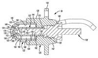
- FIG. 4is a perspective cross-sectional view of the burner
- FIG. 5is a cross-sectional view of the burner
- FIG. 6is a perspective view of a nozzle assembly of the burner
- FIG. 7is a cross-sectional view of the nozzle assembly taken along line 7 - 7 of FIG. 6 ;
- FIG. 8is a cross-sectional view of the nozzle assembly taken along line 8 - 8 of FIG. 6 ;
- FIG. 9is a cross-sectional view of the nozzle assembly taken along line 9 - 9 of FIG. 6 ;
- FIG. 10is a flow chart illustrating operation of a flame sensor of the burner
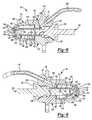
- FIG. 11is a cross-sectional view of the burner installed in a mixer housing according to the principles of the present disclosure
- FIG. 12is a perspective cross-sectional view of the burner and mixer housing of FIG. 11 ;
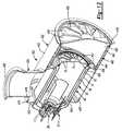
- FIG. 13is a side view of the mixer housing of FIG. 11 .
- Example embodimentsare provided so that this disclosure will be thorough, and will fully convey the scope to those who are skilled in the art. Numerous specific details are set forth such as examples of specific components, devices, and methods, to provide a thorough understanding of embodiments of the present disclosure. It will be apparent to those skilled in the art that specific details need not be employed, that example embodiments may be embodied in many different forms and that neither should be construed to limit the scope of the disclosure. In some example embodiments, well-known processes, well-known device structures, and well-known technologies are not described in detail.
- first, second, third, etc.may be used herein to describe various elements, components, regions, layers and/or sections, these elements, components, regions, layers and/or sections should not be limited by these terms. These terms may be only used to distinguish one element, component, region, layer or section from another region, layer or section. Terms such as “first,” “second,” and other numerical terms when used herein do not imply a sequence or order unless clearly indicated by the context. Thus, a first element, component, region, layer or section discussed below could be termed a second element, component, region, layer or section without departing from the teachings of the example embodiments.
- Spatially relative termssuch as “inner,” “outer,” “beneath,” “below,” “lower,” “above,” “upper,” and the like, may be used herein for ease of description to describe one element or feature's relationship to another element(s) or feature(s) as illustrated in the figures. Spatially relative terms may be intended to encompass different orientations of the device in use or operation in addition to the orientation depicted in the figures. For example, if the device in the figures is turned over, elements described as “below” or “beneath” other elements or features would then be oriented “above” the other elements or features. Thus, the example term “below” can encompass both an orientation of above and below. The device may be otherwise oriented (rotated 90 degrees or at other orientations) and the spatially relative descriptors used herein interpreted accordingly.
- FIG. 1depicts an exhaust gas aftertreatment system 10 for treating the exhaust output from an exemplary engine 12 to a main exhaust passageway 14 .
- An intake passage 16is coupled to the engine 12 to provide combustion air thereto.
- a turbocharger 18includes a driven member (not shown) positioned in an exhaust stream. During engine operation, the exhaust stream causes the driven member to rotate and provide compressed air to the intake passage 16 prior to entry into the engine 12 .
- the exhaust gas aftertreatment system 10can also be used to treat exhaust output from a naturally aspirated engine or any other engine that does not include a turbocharger.
- the exhaust aftertreatment system 10may include a burner 26 that receives and burns fuel from a fuel delivery system 98 and air from an air delivery system 110 .
- the burner 26is positioned downstream from the turbocharger 18 and upstream from a number of exhaust aftertreatment devices.
- the exhaust aftertreatment devicesmay include a hydrocarbon injector 28 , a diesel oxidation catalyst 30 and/or a diesel particulate filter 32 , for example.
- the burner 26may be positioned in a heat transfer relationship with exhaust gas flowing through the main exhaust passageway 14 . As shown in FIG. 1 , the burner 26 may be at least partially disposed within a mixer housing 400 .
- the mixer housing 400may be a part of or disposed in the main exhaust passageway 14 so that the exhaust gas may flow into the mixer housing and around the burner 26 to transfer heat between the exhaust gas and the burner 26 .
- the burner 26may be used to heat the exhaust gas passing through the main exhaust passageway 14 to an elevated temperature that will enhance the efficiency of the DOC 30 and allow regeneration of the DPF 32 . Additionally or alternatively, the burner 26 may be used prior to startup of the engine 12 to pre-heat the emissions system so that the effectiveness of the emissions system at engine startup is improved, thereby reducing cold-start emissions.
- the burner 26may include a housing assembly 40 , a nozzle assembly 36 , and a flame sensor assembly 37 .
- the housing assembly 40may be constructed as a multi-piece assembly of fabricated metal components.
- the housing assembly 40may include an outer shell 42 , an intermediate shell 44 , and an inner shell 46 .
- the outer, intermediate and inner shells 42 , 44 , 46may be substantially concentric with each other such that the outer and intermediate shells 42 , 44 may cooperate to define a first annular passage 48 therebetween, and the intermediate and inner shells 44 , 46 may cooperate to define a second annular passage 50 therebetween.
- the first and second annular passages 48 , 50may be in fluid communication with each other through one or more apertures 49 in the intermediate shell 44 .
- the shells 42 , 44 , 46may include generally cylindrical tube portions 51 , 52 , 54 , respectively, and generally funnel-shaped backwall portions 56 , 58 , 60 , respectively.
- the first ends 62 , 64 , 66 of respective tube portions 51 , 52 , 54may be welded or otherwise attached to first ends 68 , 70 , 72 of the backwall portions 56 , 58 , 60 , respectively.
- the second ends 74 , 78 of respective outer and inner tube portions 51 , 54may be welded or otherwise attached to a second end 76 of the intermediate tube portion 52 .
- An inner surface 96 of the inner shell 46may define a combustion chamber 94 (shown in FIGS. 4 and 5 ).
- a flame tube 95may be disposed within the combustion chamber 94 to act as a vaporizing element by inducing recirculation of oxygen-poor combustion products within the combustion chamber 94 .
- the recirculationresults in the complete vaporization of the fuel and may cause the flame within the combustion chamber 94 to be a blue flame, which is indicative of a clean-burning, low-emissions flame.
- the flame tube 95may be connected to the inner surface 96 by one or more brackets 92 .
- a vaned diffuser 77may be connected to the housing assembly 40 at or proximate the second ends 74 , 76 , 78 of the tube portions 51 , 52 , 54 and may diffuse and swirl heated air exiting the burner 26 .
- Second ends 80 , 82 , 84 of the backwall portions 56 , 58 , 60may fixedly support a nozzle bushing 86 that receives the nozzle assembly 36 .
- the nozzle bushing 86may be slidably relative to the second ends 80 , 82 , 84 to allow for thermal expansion and contraction of the intermediate and inner shells 44 , 46 relative to each other and the outer shell 42 .
- the nozzle bushing 86may be an annular member including a main aperture 87 and a recessed portion 88 .
- the recessed portion 88may be disposed adjacent the combustion chamber 94 and may include a plurality of radially extending apertures 90 in fluid communication with the second annular passage 50 .
- the nozzle assembly 36is fixedly received in the main aperture 87 .
- a portion of the nozzle assembly 36may extend at least partially through the recessed portion 88 proximate the combustion chamber 94 .
- the backwall portion 56 of the outer shell 42may include an air inlet port 119 that provides fluid communication between the air delivery system 110 and the first annular passage 48 .
- air from the air delivery system 110may flow in a serpentine flow path from the air inlet port 119 , through the first and second annular passages and into the combustion chamber 94 , as shown in FIG. 4 . That is, the air from the air delivery system 110 may flow into the air inlet port 119 , then through the first annular passage 48 . The air may then flow through the apertures 49 into the second annular passage 50 . The air may then flow through the annular passage 50 and into the combustion chamber 94 through the apertures 90 in the nozzle bushing 86 .
- the air and fuelmay be ignited. After ignition, incoming air flowing through the first and second annular passages 48 , 50 may absorb heat from the outer, intermediate and inner shells 42 , 44 , 46 and from flames in the combustion chamber 94 as the air flows through the serpentine flow path prior to combustion in the combustion chamber 94 . In this manner, the air can be preheated prior to combustion and can cool the outer, intermediate and inner shells 42 , 44 , 46 .
- the nozzle assembly 36may inject and ignite a mixture of fuel received from the fuel delivery system 98 and air received from the air delivery system 110 .
- the fuelmay be a conventional diesel fuel or any hydrocarbon-based or hydrogen-based fuel, for example.
- the nozzle assembly 36may be structured as a combined injector that injects both the fuel and air or separate injectors may be provided for the fuel and the air.
- the nozzle assembly 36may include a main body 120 , an outer nozzle body 122 , an inner nozzle body 123 , a nozzle cap 124 and a heating element such as a glow plug 126 .
- the main body 120includes a generally cylindrical member having an outer surface 128 and a radially extending flange 130 .
- the outer surface 128may be received in the main aperture 87 such that the flange 130 abuts an axial end 132 of the nozzle bushing 86 , as shown in FIGS. 4 and 5 .
- a plurality of bolts 134FIGS. 2 and 3 ) may secure the flange 130 to the nozzle bushing 86 .
- the main body 120could be secured to the nozzle bushing 86 by any other suitable means, such as welding or a press fit, for example.
- the main body 120could be integrally formed with the nozzle bushing 86 .
- the main body 120may also include a first recess 136 , a central aperture 138 and a second recess 140 .
- the glow plug 126may threadably engage the first recess 136 and may extend through the central aperture 138 and the second recess 140 .
- the outer nozzle body 122may be fixedly received in the second recess 140 .
- the inner nozzle body 123may be slidably received in the central aperture 138 to allow for axial expansion and contraction of the inner nozzle body 123 to allow for axial thermal expansion and contraction of the inner nozzle body 123 .
- the main body 120may also include a fuel inlet passage 97 (shown in FIG. 8 ) and an air inlet passage 99 (shown in FIG. 9 ).
- the fuel inlet passage 97may extend through an end 142 of the main body 120 to the first recess 136 .
- the air inlet passage 99may extend through the end 142 of the main body 120 to the second recess 140 .
- the fuel inlet passage 97is in fluid communication with the fuel delivery system 98 .
- the fuel delivery system 98may include a fuel tank 100 , a fuel filter 102 , and a fuel pump 104 interconnected by a fuel line 108 .
- the fuel pump 104may be a metering-type pump whereby a pump motor speed is increased or decreased to control the fuel delivery rate.
- the pump 104may be controlled based on feedback from the flame sensor assembly 37 .
- the fuel delivery system 98could include a fuel block (not shown) controlling delivery of the fuel.
- the fuel line 108may be directly or indirectly coupled with the fuel inlet passage 97 .
- the air inlet passage 99is in fluid communication with the air delivery system 110 .
- the air delivery system 110may include a secondary air filter 112 and a MAF sensor 114 .
- a compressor 116is in receipt of air that is passed through the secondary air filter 112 and the MAF sensor 114 .
- the compressor 116may include a portion of a supercharger, the turbocharger 18 or a stand-alone electric compressor.
- Output from the compressor 116is provided to the air inlet passage 99 via an air supply line 118 .
- the air supply line 118also supplies air to the air inlet port 119 of the outer shell 42 .
- a valve 117may be disposed downstream of the compressor 116 to control airflow into the nozzle assembly 36 and into the inlet 119 .
- the valve 117may be configured to ensure a predetermined amount of air flows into the nozzle assembly 36 .
- the valve 117may be configured so that air pressure at the inlet of the nozzle assembly 36 is about five pounds per square inch (psi) higher than air pressure at the inlet 119 . It will be appreciated, however, that the majority of the air flowing through the air supply line 118 may flow into the inlet 119 with a relatively small portion being diverted to the nozzle assembly 36 to atomize the fuel in the nozzle assembly 36 .
- the outer nozzle body 122may include a cylindrical portion 144 and a frustoconical portion 146 .
- the cylindrical portion 144may be fixedly received in the second recess 140 of the main body 120 such that the frustoconical portion 146 abuts an end of the main body 120 .
- the outer nozzle body 122may be welded or otherwise fixed to the main body 120 .
- the outer nozzle body 122may also include first and second recesses 148 , 150 .
- the first recess 148may be partially defined by an annular flange 152 .
- the second recess 150may extend from an axial end of the cylindrical portion 144 through a portion of the frustoconical portion 146 and into the first recess 148 .
- the second recess 150may be defined by a cylindrical annular surface 153 and a tapered annular surface 154 adjacent the first recess 148 .
- the inner nozzle body 123may include a body portion 156 , a and a head portion 158 .
- the body portion 156may extend from the first recess 136 of the main body 120 through the central aperture 138 and through a portion of the second recess 140 .
- the body portion 156may include an outer surface 160 and an inner surface 162 .
- the outer surface 160may include a cylindrical portion 164 and a tapered portion 166 .
- the cylindrical portion 164may be received in the central aperture 138 by a slip fit, for example.
- the cylindrical portion 164 and the tapered portion 166 of the outer surface 160may cooperate with the cylindrical annular surface 153 and the tapered annular surface 154 , respectively, of the outer nozzle body 122 to define an annular passageway 168 (i.e., a first cavity) in fluid communication with the air inlet passage 99 .
- the inner surface 162 of the body portion 156 of the inner nozzle body 123may define a generally cylindrical interior cavity 170 (i.e., a second cavity) having a tapered end 172 .
- the interior cavity 170may be in fluid communication with the fuel inlet passage 97 via the first recess 136 .
- the head portion 158 of the inner nozzle body 123may extend radially outward from an end of the tapered portion 166 of the body portion 156 .
- the nozzle cap 124 and head portion 158may be received in the first recess 148 of the outer nozzle body 122 .
- the nozzle cap 124may be welded to the outer nozzle body 122 , thereby securing the head portion 158 within the first recess 148 .
- the head portion 158may include a fuel discharge passage or aperture 174 and a plurality of air discharge passages or apertures 176 .
- the fuel discharge aperture 174may be in fluid communication with the interior cavity 170 and an exit aperture 178 of the nozzle cap 124 .
- the air discharge apertures 176may be in fluid communication with the annular passageway 168 and the exit aperture 178 of the nozzle cap 124 . Fuel discharged from the fuel discharge aperture 174 may be atomized in the exit aperture 178 and/or downstream of the exit aperture 178 by the high-pressure air discharged from the air discharge apertures 176 .
- the glow plug 126may include a bushing portion 180 and a heater rod 182 .
- the glow plug 126can be a 120 W Kyocera SiN glow plug, for example, or any other suitable glow plug or other heating element.
- the bushing portion 180may be threadably received in the first recess 136 of the main body 120 .
- the heater rod 182may extend from the bushing portion 180 into the interior cavity 170 .
- the heater rod 182 and the interior cavity 170may be sized such that an annular space 184 exists between the heater rod 182 and the inner surface 162 of the body portion 156 of the inner nozzle body 123 .
- nozzle assembly 36is described above as including an integrated glow plug, additionally or alternatively, a spark plug or other ignition device could be provided for igniting the fuel and air.
- the spark plug or other ignition devicecould be separate and distinct from the nozzle assembly 36 or integrated therein.
- a control module 38( FIG. 1 ) is provided to monitor and control the flows of fuel and air through the nozzle assembly 36 and monitor and control operation of the glow plug 126 using any suitable processor(s), sensors, flow control valves, electric coils, etc.
- the control module 38may include or be part of an Application Specific Integrated Circuit (ASIC), an electronic circuit, a processor (shared, dedicated or group) and/or memory (shared, dedicated or group) that execute one or more software or firmware programs, a combinational logic circuit and/or other suitable components that provide the described functionality.
- the control module 38may be a part of or include a control unit controlling one or more other vehicle systems. Alternatively, the control module 38 may be a control unit dedicated to the exhaust aftertreatment system 10 .
- the control module 38may operate the glow plug 126 in one of a plurality of operational modes to serve specific purposes. For example, the control module 38 may operate the glow plug 126 at a high power level to heat the fuel in the inner nozzle body 123 to a temperature beyond the fuel's auto-ignition point so that when the fuel comes into contact with pressurized air in the exit aperture 178 and/or in the combustion chamber 94 , the fuel will spontaneously ignite. Once the burner 26 is lit, the control module 38 may discontinue or reduce the electrical power to the glow plug 126 to reduce the temperature of the glow plug 126 to a point at which the glow plug 126 preheats the fuel to allow for passive vaporization of the fuel in the flame tube 95 .
- the glow plug 126may be operated in a cleaning mode or decoking mode.
- the supply of fuel to the nozzle assembly 36may be shut off and the glow plug temperature may be increased to burn off any varnish and/or carbon deposits that may have accumulated on the nozzle assembly 36 .
- the glow plug 126may be powered down to a low level and the temperature of the glow plug 126 may be monitored (it will be appreciated that the temperature of the glow plug 126 may be monitored at any time during operation of the glow plug 126 ). Monitoring of the glow plug temperature may be accomplished by way of a calculation based on the resistance of the glow plug 126 , which can be determined based on the voltage and current supplied to the glow plug 126 . In some embodiments, air may continue to be pumped through the nozzle assembly 36 during the cleaning and/or monitoring cycles to prevent soot and/or other debris from entering the nozzle assembly 36 from the combustion chamber 94 .
- the control module 38may adjust a power level (e.g., a pulse width modulation duty cycle) of the glow plug 126 based on the temperature of the glow plug 126 . In this manner, the control module 38 may supply no more electrical power than is necessary to achieve a particular purpose. Monitoring the glow plug temperature and adjusting the power level accordingly can also ensure that the glow plug 126 is not heated beyond its rated temperature threshold, nor subjected to thermal shock due to heating and/or cooling faster than a threshold rate, thereby preventing damage to the glow plug 126 due to overheating.
- a power levele.g., a pulse width modulation duty cycle
- the flame sensor assembly 37may be supported by the backwall portions 56 , 58 , 60 of the housing assembly 40 .
- the flame sensor assembly 37may include a bushing 190 , a flame rod 192 , an insulator 193 , and a heating element 194 (shown schematically in FIG. 5 ).
- the bushing 190may engage one or more of the backwall portions 56 , 58 , 60 and may receive the flame rod 192 and insulator 193 .
- the insulator 193may be a tube formed from Alumina and may surround a portion of the flame rod 192 .
- the heating element 194may be embedded in the insulator 193 at a location proximate the backwall 60 (i.e., at the entry point to the combustion chamber 94 ).
- the insulator 193may pass through and slidably engage the backwalls 58 , 60 , and clearance may be managed to reduce leakage of air therebetween.
- the flame rod 192may be an elongated high-temperature wire including an electrode 196 that may be positioned at least partially within or proximate the combustion chamber 94 .
- a bias voltagemay be applied to the flame sensor 192 to create an electric field from the electrode 196 to a ground such as the inner shell 46 . When voltage is applied, an electric field may radiate from the electrode 196 to the ground. If free ions are present in the field, an ion current may flow. The magnitude of the ion current provides an indication of the density of the ions.
- the control module 38detects and receives signals from the flame sensor assembly 37 indicative of the ion current to determine the presence or absence of a flame within the combustion chamber 94 .
- the sensor assembly 37may also determine if the insulator 193 is fouled. While the flame sensor 192 is described above as being an ion sensor, it will be appreciated that, in some embodiments, the flame sensor 192 could include any other type of flame sensor such as an optical sensor or a thermocouple, for example.
- the heating element 194 of the sensor assembly 37may be include a resistance heater embedded in the insulator, for example, or any suitable electrical resistance heating device.
- the heating element 194is in conductive heat transfer relation with the insulator 193 and may be coaxial with the electrode 196 .
- the insulator 193may electrically isolate the heating element 194 from the electrode 196 and any metallic components of the housing assembly 40 and may act as a heat-resistant structural support.
- the heating element 194may be at least partially disposed in the combustion chamber 94 . In an exemplary embodiment, the heating element 194 may span at least about 10 mm in length and may be disposed about 20 mm from a distal tip of the electrode 196 .
- the heating element 194may be operable in a cleaning or decoking mode and in a monitoring mode.
- the control module 38may cause electrical current to be applied to the heating element 194 to burn off any deposits and/or contamination that may accumulate on the insulator 193 due to exposure to exhaust gases and/or combustion in the combustion chamber 94 .
- the control module 38may apply a reduced electrical current to the heating element 194 and determine a resistance of the heating element 194 based on the voltage and current applied to the heating element 194 . From the resistance, the temperature of the heating element 194 can be calculated or determined from a lookup table. In this manner, the control module 38 can use the heating element 194 as a combustion chamber temperature sensor.
- the temperature of the heating element 194indicates the temperature of the combustion chamber 94 .
- the control module 38may compare temperature data acquired from the heating element 194 with data from the flame sensor 192 . If the data from the heating element 194 indicates the presence of a flame in the combustion chamber 94 and the flame sensor 192 does not indicate the presence of a flame, the control module 38 may operate the burner 26 in a reduced capacity mode or a “limp mode” rather than completely disabling the burner 26 .
- Fouling of the insulator 193may occur through deposition of soot, oil and/or other contaminants that form a conductive bridge from the flame rod 196 to ground where the insulator passes through the backwall 60 .
- the control module 38may determine whether the insulator 193 is sufficiently clean to allow the flame sensor assembly 37 to function correctly prior to ignition of the burner 26 . If the flame sensor assembly 37 is determined to be ready for operation, the control module 38 may ignite the burner 26 .
- the control module 38may evaluate a number of other parameters including presence of combustion and temperature of the exhaust gas within the main exhaust passageway 14 at a location downstream from the burner 26 to determine when to cease the supply of fuel and air to the burner 26 .
- the control module 38may receive signals from one or more temperature sensors located within the burner 26 or within the main exhaust passageway 14 to perform a closed loop control by operating the burner 26 to maintain a desired temperature at a particular location. If combustion unexpectedly extinguishes, the control module 38 may cease the supply of fuel and/or attempt to relight the burner 26 .
- Other control schemesare also within the scope of the present disclosure.
- the control module 38may cause a bias voltage to be applied to the flame sensor 192 .
- a resulting current flow through the flame sensor 192may be determined.
- the control module 38may determine whether the current flow through the flame sensor 192 (determined at step 220 ) is less than or greater than a predetermined value. Any appreciable current flow through the flame sensor 192 when a flame is not present in the combustion chamber 94 indicates that soot and/or other contaminants have accumulated on the insulator 193 and the detected current flow is a leakage current flow through contamination on the insulator 193 . Therefore, the predetermined value may be a very small value or any value that indicates an amount of contamination on the insulator 193 that could affect the performance of the flame sensor 192 .
- the control module 38may cause the heating element 194 to operate in the decoking mode at step 240 .
- electrical powermay be applied to the heating element 194 by pulse-width modulation, for example, to raise the heating element 194 to a temperature (e.g., about 650 degrees Celsius or more) that will burn soot deposits and/or other contamination off of the insulator 193 .
- the control module 38may vary the duty cycle of the pulse-width modulated power to the heating element 194 to control the temperature of the heating element 194 .
- the temperature of the heating element 194may be determined by first calculating the resistance of the heating element 194 based on a known voltage and detected current flow therethrough. The temperature of the heating element 194 can then be determined based on the resistance by way of a calculation or a lookup table, for example.
- the control module 38may continue to monitor the current flowing through the flame sensor 192 , as described above with respect to steps 210 - 230 . As the soot and/or other contaminants are burned off of the insulator 193 , the current through the flame sensor 192 may drop off to an acceptable level. Once the current flow has reached an acceptable level, the control module 38 may cause the heating element 194 to operate in the monitor mode at step 250 .
- the control module 38may cause a reduced duty cycle to be applied to the heating element 194 .
- the duty cycle applied to the heating element 194 in the monitor modemay be any duty cycle that allows calculation of the electrical resistance of the heating element 194 so that the temperature of the heating element 194 can be monitored.
- the heating element 194may provide feedback to the control module 38 indicating the temperature of the combustion chamber 94 and whether a flame is present in the combustion chamber 94 .
- no more currentis provided to the heating element 194 in the monitor mode than is necessary to calculate the resistance of the heating element 194 .
- the control module 38may determine whether conditions are such that the burner 26 should be operated to heat exhaust gas in the main exhaust passageway 14 and/or one or more of the aftertreatment devices. If the control module 38 determines that the burner 26 should be operated, the control module 38 may, at step 260 , operate the burner 26 and continue to operate the flame sensor assembly 37 . That is, fuel and air may be supplied to the burner 26 and ignited therein, and voltage may be applied to the flame sensor 192 . At step 270 , the control module 38 may determine the ion current flow through the flame sensor 192 as a result of the bias voltage applied thereto.
- the control module 38may determine whether the ion current flow through the flame sensor 192 indicates the presence of a flame in the combustion chamber 94 . If data from the flame sensor 192 indicates that a flame is present in the combustion chamber 94 , the control module 38 may determine, at step 290 , whether temperature data received from the heating element 194 (during operation of the heating element 194 in the monitor mode) also indicates the presence of a flame in the combustion chamber 94 . If temperature data from the heating element 194 also indicates the presence of a flame in the combustion chamber 94 , operation of the burner 26 may continue, as necessary.
- control module 38may operate the burner 26 in a reduced capacity mode or a limp mode at step 300 .
- the control module 38may also generate an error signal that may alert the driver of the vehicle that a fault has been detected in the aftertreatment system 10 and that service of the aftertreatment system 10 may be necessary.
- the control module 38may determine, at step 310 , whether temperature data received from the heating element 194 also indicates the lack of a flame in the combustion chamber 94 . If temperature data from the heating element 194 also indicates the lack of a flame in the combustion chamber 94 , the control module 38 may shutdown the burner 26 (i.e., discontinue the supply of fuel and air to the burner 26 ) at step 320 .
- control module 38may operate the burner 26 in a reduced capacity mode or a limp mode at step 300 and generate an error signal alerting the driver that a fault has been detected in the aftertreatment system 10 .
- the control module 38may account for the lagging response-time of the heating element 194 when determining (at steps 290 and 310 ) whether temperature data from the heating element 194 indicates the presence or lack of a flame in the combustion chamber 94 .
- the mixer housing 400may support the burner 26 relative to the main exhaust passageway 14 and may fluidly couple upstream and downstream portions 401 , 403 ( FIGS. 1 and 11 ) of the main exhaust passageway 14 .
- the mixer housing 400may include a main body 402 , an inlet body 404 , a first vaned diffuser 406 and a second vaned diffuser 408 .
- the main body 402may include a tubular shell 410 and an annular backwall 412 .
- the tubular shell 410may include first and second axial ends 414 , 416 and an inlet opening 418 disposed between the first and second axial ends 414 , 416 .
- the backwall 412may be fixedly attached to or integrally formed with the tubular shell 410 at the first axial end 414 .
- the first diffuser 406may be disposed within the tubular shell 410 and may be fixed relative thereto between the inlet opening 418 and the second axial end 416 .
- the second diffuser 408may be fixedly attached to the tubular shell 410 at or proximate the second axial end 414 .
- the mixer housing 400may define a first chamber 420 within the tubular shell 410 between the backwall 412 and the first diffuser 406 and a second chamber 422 within the tubular shell 410 between the first and second diffusers 406 , 408 .
- the second axial end 414 and the second diffuser 408may define an outlet of the second chamber 422 that is fluidly coupled with the downstream portion 403 of the main exhaust passageway 14 .
- the first diffuser 406 and the backwall 412may both be annular members including central openings 424 , 426 , respectively.
- the burner 26may extend through the openings 424 , 426 and the outer shell 42 of the burner 26 may fixedly engage the backwall 412 and the first diffuser 406 . In this manner, at least a portion of the housing assembly 40 of the burner 26 may be received in the first chamber 420 .
- the tube portions 51 , 52 , 54 of the housing assembly 40 of the burner 26may be substantially concentric with the tubular shell 410 of the mixer housing 400 (i.e., the tube portions 51 , 52 , 54 may share a common longitudinal axis A1 with the tubular shell 410 ). It will be appreciated, however, that in some embodiments, the tube portions 51 , 52 , 54 may be eccentric relative to the tubular shell 410 .
- the second ends 74 , 76 , 78 of the tube portions 51 , 52 , 54 of the housing assembly 40may extend into the second chamber 422 such that heated air and combustion gas may exit the burner 26 through its diffuser 77 and flow into the second chamber 422 where the heated air and combustion gas may mix with exhaust gas from the main exhaust passageway 14 .
- the mixture of exhaust gas and heated gas from the burner 26may exit the mixer housing 400 through the second diffuser 408 and flow into the downstream portion 403 of the main exhaust passageway 14 .
- the inlet body 404may be a tubular member including a longitudinal axis A2, a first axial end 430 and a second axial end 432 .
- the first axial end 430may be fluidly coupled with the upstream portion 401 of the main exhaust passageway 14 .
- the second axial end 432may be fluidly coupled with the inlet opening 418 of the main body 402 . In this manner, the inlet body 404 feeds exhaust gas from the upstream portion 401 of the main exhaust passageway 14 into the first chamber 420 of the mixer housing 400 .
- the inlet body 404may be positioned relative to the main body 402 such that the longitudinal axis A2 of the inlet body 404 may be substantially perpendicular to the longitudinal axis A1 of the tubular shell 410 (as shown in FIGS. 11 and 13 ) and offset from the longitudinal axis A1 so that the longitudinal axes A1, A2 do not intersect each other (as shown in FIG. 13 ).
- the axis A2may be parallel to and intersect the axis A1 (i.e., the inlet body 404 may extend radially from the main body 402 ).
- the offset position of the inlet body 404 relative to the main body 402 shown in FIG. 13may allow at least a portion of the exhaust gas to enter the first chamber 420 generally tangentially.
- This tangential flow into the first chamber 420may induce a swirled flow within the first chamber 420 and may facilitate a more uniform flow of the exhaust gas through the annular space around the housing assembly 40 , thereby improving the transfer of heat from the exterior surfaces of the housing assembly 40 to the exhaust gas.
- the exhaust gas in the first chamber 420may be fluidly isolated from the air and combustion gas within the burner 26 until the exhaust gas and the air and combustion gas from the burner 26 are combined in the second chamber 422 .
- the exhaust gasmay flow through the first diffuser 406 and into the second chamber 422 .
- Vanes 407 of the first diffuser 406may further induce swirling of the exhaust gas passing therethrough.
- the vanes 75 of diffuser 77 of the burner 26may induce swirling of the heated air and combustion gas exiting the burner 26 .
- the swirling flow of exhaust gas, heated air and combustion gas within the second chamber 422may facilitate mixing of the exhaust gas with the heated air and combustion gas and facilitate heating of the exhaust gas in the second chamber 422 .
- the vanes 409 of the second diffuser 408may further induce swirling of the mixture of the exhaust gas and heated air and combustion gas as it exits the second chamber 422 and flows into the downstream portion 403 of the main exhaust passageway 14 . In this manner, the exhaust gas in the downstream portion 403 of the main exhaust passageway 14 may be sufficiently heated prior to interaction with the aftertreatment devices 28 , 30 , 32 ( FIG. 1 ).
- the vanes 75 , 407 , 409 of the diffusers 77 , 406 , 408may all be angled or oriented in the same direction so that the diffusers 77 , 406 , 408 all generate a swirling effect in the same rotational direction.
- one of the sets of vanes 75 , 407 , 409may be angled or oriented in the opposite direction so that one of the diffusers 77 , 406 , 408 generates a swirling effect in an opposite rotational direction relative to the rotational directions of the swirling effects of the other two diffusers 77 , 406 , 408 .
- the main body 402may include an insulation member 440 ( FIG. 11 ) that lines the inner diameter of the tubular shell 410 in the second chamber 422 .
- the insulation member 440may include an annular shell 442 encasing a fibrous insulation material 444 , for example, and may reduce heat loss from the second chamber 422 (i.e., reduce the transfer of heat from the second chamber 422 to the ambient environment). This improves the efficiency of the mixer housing 400 and burner 26 and also maintains the outer surface of the tubular shell 410 at a relatively moderate temperature.
Landscapes
- Engineering & Computer Science (AREA)
- Chemical & Material Sciences (AREA)
- Chemical Kinetics & Catalysis (AREA)
- Combustion & Propulsion (AREA)
- Mechanical Engineering (AREA)
- General Engineering & Computer Science (AREA)
- Health & Medical Sciences (AREA)
- Toxicology (AREA)
- Exhaust Gas After Treatment (AREA)
- Processes For Solid Components From Exhaust (AREA)
Abstract
Description
Claims (13)
Priority Applications (5)
| Application Number | Priority Date | Filing Date | Title |
|---|---|---|---|
| US13/778,682US8991163B2 (en) | 2013-02-27 | 2013-02-27 | Burner with air-assisted fuel nozzle and vaporizing ignition system |
| DE112014001011.1TDE112014001011B4 (en) | 2013-02-27 | 2014-02-14 | Burner for an exhaust aftertreatment system and exhaust aftertreatment system |
| PCT/US2014/016440WO2014133786A1 (en) | 2013-02-27 | 2014-02-14 | Burner with air-assisted fuel nozzle and vaporizing ignition system |
| CN201480010835.3ACN105026712B (en) | 2013-02-27 | 2014-02-14 | Burner with air-assisted fuel nozzle and vaporization ignition system |
| US14/639,382US20150176449A1 (en) | 2013-02-27 | 2015-03-05 | Burner With Air-Assisted Fuel Nozzle And Vaporizing Ignition System |
Applications Claiming Priority (1)
| Application Number | Priority Date | Filing Date | Title |
|---|---|---|---|
| US13/778,682US8991163B2 (en) | 2013-02-27 | 2013-02-27 | Burner with air-assisted fuel nozzle and vaporizing ignition system |
Related Child Applications (1)
| Application Number | Title | Priority Date | Filing Date |
|---|---|---|---|
| US14/639,382DivisionUS20150176449A1 (en) | 2013-02-27 | 2015-03-05 | Burner With Air-Assisted Fuel Nozzle And Vaporizing Ignition System |
Publications (2)
| Publication Number | Publication Date |
|---|---|
| US20140238000A1 US20140238000A1 (en) | 2014-08-28 |
| US8991163B2true US8991163B2 (en) | 2015-03-31 |
Family
ID=51386728
Family Applications (2)
| Application Number | Title | Priority Date | Filing Date |
|---|---|---|---|
| US13/778,682Active2033-05-16US8991163B2 (en) | 2013-02-27 | 2013-02-27 | Burner with air-assisted fuel nozzle and vaporizing ignition system |
| US14/639,382AbandonedUS20150176449A1 (en) | 2013-02-27 | 2015-03-05 | Burner With Air-Assisted Fuel Nozzle And Vaporizing Ignition System |
Family Applications After (1)
| Application Number | Title | Priority Date | Filing Date |
|---|---|---|---|
| US14/639,382AbandonedUS20150176449A1 (en) | 2013-02-27 | 2015-03-05 | Burner With Air-Assisted Fuel Nozzle And Vaporizing Ignition System |
Country Status (4)
| Country | Link |
|---|---|
| US (2) | US8991163B2 (en) |
| CN (1) | CN105026712B (en) |
| DE (1) | DE112014001011B4 (en) |
| WO (1) | WO2014133786A1 (en) |
Cited By (12)
| Publication number | Priority date | Publication date | Assignee | Title |
|---|---|---|---|---|
| US11613003B2 (en) | 2020-01-24 | 2023-03-28 | General Electric Company | Line assembly for an extension tool having a plurality of links |
| US11654547B2 (en) | 2021-03-31 | 2023-05-23 | General Electric Company | Extension tool |
| US11692650B2 (en) | 2020-01-23 | 2023-07-04 | General Electric Company | Selectively flexible extension tool |
| US11702955B2 (en) | 2019-01-14 | 2023-07-18 | General Electric Company | Component repair system and method |
| US11707819B2 (en) | 2018-10-15 | 2023-07-25 | General Electric Company | Selectively flexible extension tool |
| US11752622B2 (en) | 2020-01-23 | 2023-09-12 | General Electric Company | Extension tool having a plurality of links |
| US11834990B2 (en) | 2020-03-10 | 2023-12-05 | Oliver Crispin Robotics Limited | Insertion tool |
| US12091981B2 (en) | 2020-06-11 | 2024-09-17 | General Electric Company | Insertion tool and method |
| US12194620B2 (en) | 2018-10-15 | 2025-01-14 | Oliver Crisipin Robotics Limited | Selectively flexible extension tool |
| US12395007B1 (en) | 2022-06-29 | 2025-08-19 | Kazem Ganji | Solar power system with electric engine |
| US12405187B2 (en) | 2019-10-04 | 2025-09-02 | General Electric Company | Insertion apparatus for use with rotary machines |
| US12416800B2 (en) | 2021-01-08 | 2025-09-16 | General Electric Company | Insertion tool |
Families Citing this family (19)
| Publication number | Priority date | Publication date | Assignee | Title |
|---|---|---|---|---|
| US9027331B2 (en) | 2013-02-27 | 2015-05-12 | Tenneco Automotive Operating Company Inc. | Exhaust aftertreatment burner with preheated combustion air |
| US9027332B2 (en)* | 2013-02-27 | 2015-05-12 | Tenneco Automotive Operating Company Inc. | Ion sensor with decoking heater |
| US8991163B2 (en) | 2013-02-27 | 2015-03-31 | Tenneco Automotive Operating Company Inc. | Burner with air-assisted fuel nozzle and vaporizing ignition system |
| US8959902B2 (en) | 2013-02-27 | 2015-02-24 | Tenneco Automotive Operating Company Inc. | Exhaust treatment burner and mixer system |
| US9534525B2 (en) | 2015-05-27 | 2017-01-03 | Tenneco Automotive Operating Company Inc. | Mixer assembly for exhaust aftertreatment system |
| US20150377108A1 (en)* | 2015-09-04 | 2015-12-31 | Caterpillar Inc. | Dual fuel engine system |
| JP2017089985A (en)* | 2015-11-11 | 2017-05-25 | 株式会社荏原製作所 | Exhaust gas treatment device |
| CN106014552A (en)* | 2016-05-18 | 2016-10-12 | 同济大学 | Exhaust gas temperature control system |
| CA3051492A1 (en)* | 2016-11-21 | 2018-05-24 | Clean Train Propulsion | Internal combustion engine aftertreatment heating loop |
| CN107013286A (en)* | 2017-05-26 | 2017-08-04 | 凯龙高科技股份有限公司 | A kind of diesel engine DPF blast pipes fuel oil and air pre-mixing close injection apparatus |
| KR101867540B1 (en)* | 2018-04-03 | 2018-06-15 | 화이버텍(주) | Apparatus for reducing exhaust gas |
| TWI685635B (en)* | 2018-09-21 | 2020-02-21 | 關隆股份有限公司 | Smoke removal device |
| US10871289B2 (en) | 2018-11-27 | 2020-12-22 | Grand Mate Co., Ltd. | Smoke removal device |
| IT202000017989A1 (en)* | 2020-07-24 | 2022-01-24 | Marelli Europe Spa | HEATER DEVICE FOR AN EXHAUST SYSTEM OF AN INTERNAL COMBUSTION ENGINE |
| US11585279B2 (en) | 2020-08-12 | 2023-02-21 | Pratt & Whitney Canada Corp. | Systems and methods for controlling a bleed-off valve of a gas turbine engine |
| CN114635774B (en)* | 2022-03-04 | 2024-07-19 | 潍柴动力股份有限公司 | Cold start tail gas temperature control method and system for diesel engine |
| DE102022002114B4 (en)* | 2022-06-13 | 2024-01-11 | Mercedes-Benz Group AG | Burner for a motor vehicle and motor vehicle with at least one such burner |
| DE102022213545A1 (en) | 2022-12-13 | 2024-06-13 | Robert Bosch Gesellschaft mit beschränkter Haftung | Air supply to an internal combustion engine and method and device for diagnosing an air supply to an internal combustion engine |
| DE102022213542A1 (en)* | 2022-12-13 | 2024-06-13 | Robert Bosch Gesellschaft mit beschränkter Haftung | Air supply to an internal combustion engine and method and device for diagnosing an air supply to an internal combustion engine |
Citations (60)
| Publication number | Priority date | Publication date | Assignee | Title |
|---|---|---|---|---|
| US1848990A (en) | 1927-08-13 | 1932-03-08 | Gen Motors Res Corp | Exhaust gas treatment |
| US2127977A (en) | 1935-09-07 | 1938-08-23 | Weston Electrical Instr Corp | Thermionic relay circuits |
| US2621477A (en) | 1948-06-03 | 1952-12-16 | Power Jets Res & Dev Ltd | Combustion apparatus having valve controlled passages for preheating the fuel-air mixture |
| US2628475A (en) | 1946-06-26 | 1953-02-17 | Socony Vacuum Oil Co Inc | Jet combustion device embodying pretreatment of fuel before combustion |
| US2797745A (en) | 1957-07-02 | rowell | ||
| US3136353A (en) | 1962-03-01 | 1964-06-09 | Combustion Eng | Burner means including flame rod detector with internal electric heating |
| US3174526A (en) | 1960-08-23 | 1965-03-23 | Linde Robert Albert Von | Atomizing burner unit |
| USRE29978E (en)* | 1974-06-21 | 1979-05-01 | Fuel Injection Development Corporation | Fuel vapor injector and igniter system for internal combustion engines |
| US4255122A (en) | 1977-02-23 | 1981-03-10 | Forenade Fabriksverken | Apparatus for combusting liquid, gaseous or powdered fuels |
| US4364725A (en) | 1977-01-08 | 1982-12-21 | Deutsche Forschungs- Und Versuchsanstalt Fur Luft- Und Raumfahrt E.V. | Blue-flame oil burner |
| US4364724A (en) | 1978-06-02 | 1982-12-21 | Forenade Farbiksverken | Method and apparatus for dosing an air-fuel mixture in burners having evaporating tubes |
| US4408983A (en) | 1980-08-29 | 1983-10-11 | British Gas Corporation | Recuperative burners |
| US4465046A (en) | 1980-10-17 | 1984-08-14 | May Michael G | Method and apparatus for controlling the combustion process of an internal combustion engine |
| US4576617A (en)* | 1983-06-16 | 1986-03-18 | Regie Nationale Des Usines Renault | Apparatus comprising the combination of filter apparatus and regeneration apparatus and process for regenerating the filter apparatus using the regeneration apparatus |
| US4588372A (en) | 1982-09-23 | 1986-05-13 | Honeywell Inc. | Flame ionization control of a partially premixed gas burner with regulated secondary air |
| US4657504A (en) | 1985-06-28 | 1987-04-14 | Chugai Ro Co., Ltd. | Combustion burner |
| US4684341A (en)* | 1985-06-27 | 1987-08-04 | Isuzu Motors, Ltd. | Fuel vaporization apparatus for combustor |
| US4825658A (en) | 1987-12-11 | 1989-05-02 | General Electric Company | Fuel nozzle with catalytic glow plug |
| US4944153A (en)* | 1987-08-28 | 1990-07-31 | Webasto Ag Fahrzeugtechnik | Burner for hard-to-ignite mixtures |
| US4951464A (en) | 1987-09-05 | 1990-08-28 | Deutsche Forschungsanstalt Fur Luft- Und Raumfahrt E.V. | Carbon black filter means for a Diesel engine |
| US5090896A (en)* | 1988-10-31 | 1992-02-25 | J. Eberspacher | Central heating for motor vehicles and such mobile units |
| US5140814A (en) | 1990-01-25 | 1992-08-25 | Man Technologie Ag | Exhaust gas system with an particulate filter and a regenerating burner |
| JPH0548410B2 (en) | 1984-11-21 | 1993-07-21 | Ngk Spark Plug Co | |
| US5320523A (en) | 1992-08-28 | 1994-06-14 | General Motors Corporation | Burner for heating gas stream |
| US5417059A (en)* | 1992-11-20 | 1995-05-23 | Pierburg Gmbh | Burner system for detoxification or cleaning the exhaust gases of an internal combustion engine |
| US5437123A (en)* | 1993-11-08 | 1995-08-01 | Hydrogen Burner Techn Inc | Underoxidized burner utilizing improved injectors |
| US5546701A (en)* | 1994-09-20 | 1996-08-20 | Hydrogen Burner Technology, Inc. | Underoxidized burner utilizing improved injectors |
| US5571484A (en) | 1995-04-25 | 1996-11-05 | General Motors Corporation | Catalytic converter heater |
| US5590526A (en) | 1995-05-08 | 1997-01-07 | Lg Electronics Inc. | Burner for stirling engines |
| US5617721A (en) | 1995-08-14 | 1997-04-08 | General Motors Corporation | Exhaust catalyst preheater with flame igniter and sensor element |
| US5826428A (en) | 1995-02-09 | 1998-10-27 | J. Eberspacher Gmbh & Co. | Burner for the thermal regeneration of a particle filter in an exhaust gas aftertreatment system of an internal combustion engine, especially a diesel engine |
| US5829248A (en) | 1997-06-19 | 1998-11-03 | Environmental Engineering Corp. | Anti-pollution system |
| US5944510A (en)* | 1996-11-01 | 1999-08-31 | Greiner; Leonard | Dynamic fluid injector |
| US6540151B1 (en)* | 2000-02-02 | 2003-04-01 | Eberspacher Gmbh & Co. | Heater, especially an engine-independent vehicle heating system |
| US20050048430A1 (en) | 2003-08-25 | 2005-03-03 | Steiner Michael C. | Burner apparatus |
| US20060101811A1 (en) | 2004-10-29 | 2006-05-18 | Jan-Roger Linna | Reducing agent metering system for reducing NOx in lean burn internal combustion engines |
| US20060162690A1 (en) | 2005-01-26 | 2006-07-27 | Kim Jay S | Fluid swirling device having rotatable vanes |
| US20060283181A1 (en) | 2005-06-15 | 2006-12-21 | Arvin Technologies, Inc. | Swirl-stabilized burner for thermal management of exhaust system and associated method |
| US20070169469A1 (en) | 2005-07-26 | 2007-07-26 | Knitt Andrew A | Particulate loading monitoring system |
| US20070245718A1 (en) | 2006-04-24 | 2007-10-25 | Cheng C R | Exhaust aftertreatment mixer with stamped muffler flange |
| US20080092532A1 (en)* | 2004-10-26 | 2008-04-24 | Marc Bareis | Device And Method For Producing An Operating Medium For A Motor Vehicle |
| US20080307780A1 (en) | 2007-06-13 | 2008-12-18 | Iverson Robert J | Emission abatement assembly having a mixing baffle and associated method |
| US20090180937A1 (en) | 2008-01-15 | 2009-07-16 | Nohl John P | Apparatus for Directing Exhaust Flow through a Fuel-Fired Burner of an Emission Abatement Assembly |
| US20090255242A1 (en) | 2008-04-09 | 2009-10-15 | Woodward Governor Company | Low Pressure Drop Mixer for Radial Mixing of Internal Combustion Engine Exhaust Flows, Combustor Incorporating Same, and Methods of Mixing |
| US20100083925A1 (en) | 2008-09-23 | 2010-04-08 | Friedrich Boysen Gmbh & Co. Kg | Flame Glow Plug |
| US7748976B2 (en) | 2005-03-17 | 2010-07-06 | Southwest Research Institute | Use of recirculated exhaust gas in a burner-based exhaust generation system for reduced fuel consumption and for cooling |
| US7762060B2 (en) | 2006-04-28 | 2010-07-27 | Caterpillar Inc. | Exhaust treatment system |
| US20110023457A1 (en)* | 2008-06-03 | 2011-02-03 | Deutz Aktiengesellschaft | Exhaust-gas after-treatment system for an auto-ignition internal combustion engine |
| US20110146264A1 (en) | 2006-02-28 | 2011-06-23 | Subir Roychoudhury | Catalytic burner apparatus for stirling engine |
| US20110197570A1 (en) | 2010-02-18 | 2011-08-18 | Nett Technologies Inc. | Burner for Heating a Stream of Gas |
| US20110289906A1 (en) | 2009-04-27 | 2011-12-01 | Nicholas Morley | Miniature Regeneration Unit |
| US20120036847A1 (en) | 2009-04-21 | 2012-02-16 | Borgwarner Inc. | Method for improving the light-off or regeneration behavior of an aftertreatment device in a vehicle system |
| US20120124982A1 (en) | 2010-11-18 | 2012-05-24 | Charles Bell | Inlet for exhaust treatment device |
| US20120167569A1 (en) | 2009-11-09 | 2012-07-05 | Mitsubishi Heavy Industries, Ltd. | Gas turbine combustion burner |
| US20120192547A1 (en) | 2011-01-31 | 2012-08-02 | Woodward, Inc. | Dual air circuit for exhaust gas treatment |
| KR20130012734A (en) | 2011-07-26 | 2013-02-05 | 에이치케이엠엔에스(주) | Burner device for increasing temperature of exhaust gas |
| US20140238002A1 (en) | 2013-02-27 | 2014-08-28 | Tenneco Automotive Operating Company Inc. | Exhaust Treatment Burner and Mixer System |
| US20140238000A1 (en) | 2013-02-27 | 2014-08-28 | Tenneco Automotive Operating Company Inc. | Burner With Air-Assisted Fuel Nozzle And Vaporizing Ignition System |
| US8821154B2 (en) | 2010-11-09 | 2014-09-02 | Purpose Company Limited | Combustion apparatus and method for combustion control thereof |
| US20140245718A1 (en) | 2013-03-01 | 2014-09-04 | Tenneco Automotive Operating Company Inc. | Compressor for Exhaust Treatment System |
Family Cites Families (5)
| Publication number | Priority date | Publication date | Assignee | Title |
|---|---|---|---|---|
| US8006482B2 (en)* | 2007-03-02 | 2011-08-30 | Caterpillar Inc. | Method of purging fluid injector by heating |
| US8484947B2 (en)* | 2007-03-02 | 2013-07-16 | Caterpillar Inc. | Fluid injector having purge heater |
| JP5482065B2 (en) | 2009-07-14 | 2014-04-23 | 株式会社Ihi | Burner equipment |
| US8146352B2 (en)* | 2010-05-12 | 2012-04-03 | Ford Global Technologies, Llc | Diesel particulate filter control |
| JP5115873B2 (en)* | 2010-12-08 | 2013-01-09 | 株式会社デンソー | Particulate filter failure detection device |
- 2013
- 2013-02-27USUS13/778,682patent/US8991163B2/enactiveActive
- 2014
- 2014-02-14CNCN201480010835.3Apatent/CN105026712B/enactiveActive
- 2014-02-14DEDE112014001011.1Tpatent/DE112014001011B4/enactiveActive
- 2014-02-14WOPCT/US2014/016440patent/WO2014133786A1/enactiveApplication Filing
- 2015
- 2015-03-05USUS14/639,382patent/US20150176449A1/ennot_activeAbandoned
Patent Citations (61)
| Publication number | Priority date | Publication date | Assignee | Title |
|---|---|---|---|---|
| US2797745A (en) | 1957-07-02 | rowell | ||
| US1848990A (en) | 1927-08-13 | 1932-03-08 | Gen Motors Res Corp | Exhaust gas treatment |
| US2127977A (en) | 1935-09-07 | 1938-08-23 | Weston Electrical Instr Corp | Thermionic relay circuits |
| US2628475A (en) | 1946-06-26 | 1953-02-17 | Socony Vacuum Oil Co Inc | Jet combustion device embodying pretreatment of fuel before combustion |
| US2621477A (en) | 1948-06-03 | 1952-12-16 | Power Jets Res & Dev Ltd | Combustion apparatus having valve controlled passages for preheating the fuel-air mixture |
| US3174526A (en) | 1960-08-23 | 1965-03-23 | Linde Robert Albert Von | Atomizing burner unit |
| US3136353A (en) | 1962-03-01 | 1964-06-09 | Combustion Eng | Burner means including flame rod detector with internal electric heating |
| USRE29978E (en)* | 1974-06-21 | 1979-05-01 | Fuel Injection Development Corporation | Fuel vapor injector and igniter system for internal combustion engines |
| US4364725A (en) | 1977-01-08 | 1982-12-21 | Deutsche Forschungs- Und Versuchsanstalt Fur Luft- Und Raumfahrt E.V. | Blue-flame oil burner |
| US4255122A (en) | 1977-02-23 | 1981-03-10 | Forenade Fabriksverken | Apparatus for combusting liquid, gaseous or powdered fuels |
| US4364724A (en) | 1978-06-02 | 1982-12-21 | Forenade Farbiksverken | Method and apparatus for dosing an air-fuel mixture in burners having evaporating tubes |
| US4408983A (en) | 1980-08-29 | 1983-10-11 | British Gas Corporation | Recuperative burners |
| US4465046A (en) | 1980-10-17 | 1984-08-14 | May Michael G | Method and apparatus for controlling the combustion process of an internal combustion engine |
| US4588372A (en) | 1982-09-23 | 1986-05-13 | Honeywell Inc. | Flame ionization control of a partially premixed gas burner with regulated secondary air |
| US4576617A (en)* | 1983-06-16 | 1986-03-18 | Regie Nationale Des Usines Renault | Apparatus comprising the combination of filter apparatus and regeneration apparatus and process for regenerating the filter apparatus using the regeneration apparatus |
| JPH0548410B2 (en) | 1984-11-21 | 1993-07-21 | Ngk Spark Plug Co | |
| US4684341A (en)* | 1985-06-27 | 1987-08-04 | Isuzu Motors, Ltd. | Fuel vaporization apparatus for combustor |
| US4657504A (en) | 1985-06-28 | 1987-04-14 | Chugai Ro Co., Ltd. | Combustion burner |
| US4944153A (en)* | 1987-08-28 | 1990-07-31 | Webasto Ag Fahrzeugtechnik | Burner for hard-to-ignite mixtures |
| US4951464A (en) | 1987-09-05 | 1990-08-28 | Deutsche Forschungsanstalt Fur Luft- Und Raumfahrt E.V. | Carbon black filter means for a Diesel engine |
| US4825658A (en) | 1987-12-11 | 1989-05-02 | General Electric Company | Fuel nozzle with catalytic glow plug |
| US5090896A (en)* | 1988-10-31 | 1992-02-25 | J. Eberspacher | Central heating for motor vehicles and such mobile units |
| US5140814A (en) | 1990-01-25 | 1992-08-25 | Man Technologie Ag | Exhaust gas system with an particulate filter and a regenerating burner |
| US5320523A (en) | 1992-08-28 | 1994-06-14 | General Motors Corporation | Burner for heating gas stream |
| US5417059A (en)* | 1992-11-20 | 1995-05-23 | Pierburg Gmbh | Burner system for detoxification or cleaning the exhaust gases of an internal combustion engine |
| US5437123A (en)* | 1993-11-08 | 1995-08-01 | Hydrogen Burner Techn Inc | Underoxidized burner utilizing improved injectors |
| US5546701A (en)* | 1994-09-20 | 1996-08-20 | Hydrogen Burner Technology, Inc. | Underoxidized burner utilizing improved injectors |
| US5826428A (en) | 1995-02-09 | 1998-10-27 | J. Eberspacher Gmbh & Co. | Burner for the thermal regeneration of a particle filter in an exhaust gas aftertreatment system of an internal combustion engine, especially a diesel engine |
| US5571484A (en) | 1995-04-25 | 1996-11-05 | General Motors Corporation | Catalytic converter heater |
| US5590526A (en) | 1995-05-08 | 1997-01-07 | Lg Electronics Inc. | Burner for stirling engines |
| US5617721A (en) | 1995-08-14 | 1997-04-08 | General Motors Corporation | Exhaust catalyst preheater with flame igniter and sensor element |
| US5944510A (en)* | 1996-11-01 | 1999-08-31 | Greiner; Leonard | Dynamic fluid injector |
| US5829248A (en) | 1997-06-19 | 1998-11-03 | Environmental Engineering Corp. | Anti-pollution system |
| US6540151B1 (en)* | 2000-02-02 | 2003-04-01 | Eberspacher Gmbh & Co. | Heater, especially an engine-independent vehicle heating system |
| US20050048430A1 (en) | 2003-08-25 | 2005-03-03 | Steiner Michael C. | Burner apparatus |
| US6916172B2 (en) | 2003-08-25 | 2005-07-12 | L & S Cryogenics, Inc. | Burner apparatus |
| US20080092532A1 (en)* | 2004-10-26 | 2008-04-24 | Marc Bareis | Device And Method For Producing An Operating Medium For A Motor Vehicle |
| US20060101811A1 (en) | 2004-10-29 | 2006-05-18 | Jan-Roger Linna | Reducing agent metering system for reducing NOx in lean burn internal combustion engines |
| US20060162690A1 (en) | 2005-01-26 | 2006-07-27 | Kim Jay S | Fluid swirling device having rotatable vanes |
| US7748976B2 (en) | 2005-03-17 | 2010-07-06 | Southwest Research Institute | Use of recirculated exhaust gas in a burner-based exhaust generation system for reduced fuel consumption and for cooling |
| US20060283181A1 (en) | 2005-06-15 | 2006-12-21 | Arvin Technologies, Inc. | Swirl-stabilized burner for thermal management of exhaust system and associated method |
| US20070169469A1 (en) | 2005-07-26 | 2007-07-26 | Knitt Andrew A | Particulate loading monitoring system |
| US20110146264A1 (en) | 2006-02-28 | 2011-06-23 | Subir Roychoudhury | Catalytic burner apparatus for stirling engine |
| US20070245718A1 (en) | 2006-04-24 | 2007-10-25 | Cheng C R | Exhaust aftertreatment mixer with stamped muffler flange |
| US7762060B2 (en) | 2006-04-28 | 2010-07-27 | Caterpillar Inc. | Exhaust treatment system |
| US20080307780A1 (en) | 2007-06-13 | 2008-12-18 | Iverson Robert J | Emission abatement assembly having a mixing baffle and associated method |
| US20090180937A1 (en) | 2008-01-15 | 2009-07-16 | Nohl John P | Apparatus for Directing Exhaust Flow through a Fuel-Fired Burner of an Emission Abatement Assembly |
| US20090255242A1 (en) | 2008-04-09 | 2009-10-15 | Woodward Governor Company | Low Pressure Drop Mixer for Radial Mixing of Internal Combustion Engine Exhaust Flows, Combustor Incorporating Same, and Methods of Mixing |
| US20110023457A1 (en)* | 2008-06-03 | 2011-02-03 | Deutz Aktiengesellschaft | Exhaust-gas after-treatment system for an auto-ignition internal combustion engine |
| US20100083925A1 (en) | 2008-09-23 | 2010-04-08 | Friedrich Boysen Gmbh & Co. Kg | Flame Glow Plug |
| US20120036847A1 (en) | 2009-04-21 | 2012-02-16 | Borgwarner Inc. | Method for improving the light-off or regeneration behavior of an aftertreatment device in a vehicle system |
| US20110289906A1 (en) | 2009-04-27 | 2011-12-01 | Nicholas Morley | Miniature Regeneration Unit |
| US20120167569A1 (en) | 2009-11-09 | 2012-07-05 | Mitsubishi Heavy Industries, Ltd. | Gas turbine combustion burner |
| US20110197570A1 (en) | 2010-02-18 | 2011-08-18 | Nett Technologies Inc. | Burner for Heating a Stream of Gas |
| US8821154B2 (en) | 2010-11-09 | 2014-09-02 | Purpose Company Limited | Combustion apparatus and method for combustion control thereof |
| US20120124982A1 (en) | 2010-11-18 | 2012-05-24 | Charles Bell | Inlet for exhaust treatment device |
| US20120192547A1 (en) | 2011-01-31 | 2012-08-02 | Woodward, Inc. | Dual air circuit for exhaust gas treatment |
| KR20130012734A (en) | 2011-07-26 | 2013-02-05 | 에이치케이엠엔에스(주) | Burner device for increasing temperature of exhaust gas |
| US20140238002A1 (en) | 2013-02-27 | 2014-08-28 | Tenneco Automotive Operating Company Inc. | Exhaust Treatment Burner and Mixer System |
| US20140238000A1 (en) | 2013-02-27 | 2014-08-28 | Tenneco Automotive Operating Company Inc. | Burner With Air-Assisted Fuel Nozzle And Vaporizing Ignition System |
| US20140245718A1 (en) | 2013-03-01 | 2014-09-04 | Tenneco Automotive Operating Company Inc. | Compressor for Exhaust Treatment System |
Non-Patent Citations (2)
| Title |
|---|
| Tenneco/Woodward Publication entitled T.R.U.E.-Clean Max, 4 pages, dated Aug. 2012. |
| Tenneco/Woodward Publication entitled T.R.U.E.-Clean Mini, 4 pages, dated Oct. 2012. |
Cited By (13)
| Publication number | Priority date | Publication date | Assignee | Title |
|---|---|---|---|---|
| US11707819B2 (en) | 2018-10-15 | 2023-07-25 | General Electric Company | Selectively flexible extension tool |
| US12194620B2 (en) | 2018-10-15 | 2025-01-14 | Oliver Crisipin Robotics Limited | Selectively flexible extension tool |
| US12264591B2 (en) | 2019-01-14 | 2025-04-01 | General Electric Company | Component repair system and method |
| US11702955B2 (en) | 2019-01-14 | 2023-07-18 | General Electric Company | Component repair system and method |
| US12405187B2 (en) | 2019-10-04 | 2025-09-02 | General Electric Company | Insertion apparatus for use with rotary machines |
| US11692650B2 (en) | 2020-01-23 | 2023-07-04 | General Electric Company | Selectively flexible extension tool |
| US11752622B2 (en) | 2020-01-23 | 2023-09-12 | General Electric Company | Extension tool having a plurality of links |
| US11613003B2 (en) | 2020-01-24 | 2023-03-28 | General Electric Company | Line assembly for an extension tool having a plurality of links |
| US11834990B2 (en) | 2020-03-10 | 2023-12-05 | Oliver Crispin Robotics Limited | Insertion tool |
| US12091981B2 (en) | 2020-06-11 | 2024-09-17 | General Electric Company | Insertion tool and method |
| US12416800B2 (en) | 2021-01-08 | 2025-09-16 | General Electric Company | Insertion tool |
| US11654547B2 (en) | 2021-03-31 | 2023-05-23 | General Electric Company | Extension tool |
| US12395007B1 (en) | 2022-06-29 | 2025-08-19 | Kazem Ganji | Solar power system with electric engine |
Also Published As
| Publication number | Publication date |
|---|---|
| US20140238000A1 (en) | 2014-08-28 |
| WO2014133786A1 (en) | 2014-09-04 |
| CN105026712A (en) | 2015-11-04 |
| CN105026712B (en) | 2018-08-24 |
| US20150176449A1 (en) | 2015-06-25 |
| DE112014001011T5 (en) | 2015-11-05 |
| DE112014001011B4 (en) | 2023-05-04 |
Similar Documents
| Publication | Publication Date | Title |
|---|---|---|
| US8991163B2 (en) | Burner with air-assisted fuel nozzle and vaporizing ignition system | |
| US8959902B2 (en) | Exhaust treatment burner and mixer system | |
| US9027331B2 (en) | Exhaust aftertreatment burner with preheated combustion air | |
| US9027332B2 (en) | Ion sensor with decoking heater | |
| US20110289906A1 (en) | Miniature Regeneration Unit | |
| KR101168149B1 (en) | Device and Method for Producing Hot Gas, a Diesel Prticulate Filter System, an Electronic Unit, and a Computer Program Product | |
| US9140158B2 (en) | Coaxial inlet and outlet exhaust treatment device | |
| US20110283685A1 (en) | Exhaust Treatment System With Hydrocarbon Lean NOx Catalyst | |
| US20100319330A1 (en) | Burner for diesel particulate filter regeneration | |
| US8511075B2 (en) | Flame deflector for emissions control system | |
| KR100866327B1 (en) | Plasma Burner & Soot Filter | |
| WO2008108956A1 (en) | Fluid injector having purge heater | |
| JP2010078315A (en) | Flame glow plug | |
| JP5625257B2 (en) | Exhaust gas temperature riser | |
| US8584445B2 (en) | Method and system for controlling an electrically heated particulate filter | |
| KR100866328B1 (en) | Plasma Burner & Soot Filter | |
| JP6811368B2 (en) | Exhaust temperature raising device | |
| KR100866331B1 (en) | Plasma Burner & Soot Filter | |
| KR100866330B1 (en) | Plasma Burner & Soot Filter | |
| JP2020041759A (en) | Burner and ignition method of burner | |
| CN118066004A (en) | Heating device for an exhaust system of an internal combustion engine |
Legal Events
| Date | Code | Title | Description |
|---|---|---|---|
| AS | Assignment | Owner name:TENNECO AUTOMOTIVE OPERATING COMPANY INC., ILLINOI Free format text:ASSIGNMENT OF ASSIGNORS INTEREST;ASSIGNOR:OLIVIER, KEITH G.;REEL/FRAME:030060/0204 Effective date:20130227 | |
| FEPP | Fee payment procedure | Free format text:PAYOR NUMBER ASSIGNED (ORIGINAL EVENT CODE: ASPN); ENTITY STATUS OF PATENT OWNER: LARGE ENTITY | |
| AS | Assignment | Owner name:JPMORGAN CHASE BANK, N.A., AS ADMINISTRATIVE AGENT Free format text:SECURITY INTEREST;ASSIGNOR:TENNECO AUTOMOTIVE OPERATING COMPANY INC.;REEL/FRAME:034674/0291 Effective date:20141208 | |
| STCF | Information on status: patent grant | Free format text:PATENTED CASE | |
| CC | Certificate of correction | ||
| AS | Assignment | Owner name:JPMORGAN CHASE BANK, N.A., AS ADMINISTRATIVE AGENT, ILLINOIS Free format text:GRANT OF SECURITY INTEREST IN PATENT RIGHTS;ASSIGNOR:TENNECO AUTOMOTIVE OPERATING COMPANY INC.;REEL/FRAME:042809/0515 Effective date:20170512 Owner name:JPMORGAN CHASE BANK, N.A., AS ADMINISTRATIVE AGENT Free format text:GRANT OF SECURITY INTEREST IN PATENT RIGHTS;ASSIGNOR:TENNECO AUTOMOTIVE OPERATING COMPANY INC.;REEL/FRAME:042809/0515 Effective date:20170512 | |
| MAFP | Maintenance fee payment | Free format text:PAYMENT OF MAINTENANCE FEE, 4TH YEAR, LARGE ENTITY (ORIGINAL EVENT CODE: M1551); ENTITY STATUS OF PATENT OWNER: LARGE ENTITY Year of fee payment:4 | |
| AS | Assignment | Owner name:WILMINGTON TRUST, NATIONAL ASSOCIATION, AS COLLATERAL TRUSTEE, MINNESOTA Free format text:CONFIRMATORY GRANT OF SECURITY INTERESTS IN UNITED STATES PATENTS;ASSIGNORS:TENNECO INC.;TENNECO AUTOMOTIVE OPERATING COMPANY INC.;TENNECO INTERNATIONAL HOLDING CORP.;AND OTHERS;REEL/FRAME:047223/0001 Effective date:20181001 Owner name:WILMINGTON TRUST, NATIONAL ASSOCIATION, AS COLLATE Free format text:CONFIRMATORY GRANT OF SECURITY INTERESTS IN UNITED STATES PATENTS;ASSIGNORS:TENNECO INC.;TENNECO AUTOMOTIVE OPERATING COMPANY INC.;TENNECO INTERNATIONAL HOLDING CORP.;AND OTHERS;REEL/FRAME:047223/0001 Effective date:20181001 | |
| AS | Assignment | Owner name:TENNECO AUTOMOTIVE OPERATING COMPANY INC., ILLINOIS Free format text:RELEASE BY SECURED PARTY;ASSIGNOR:JPMORGAN CHASE BANK, N.A.;REEL/FRAME:048099/0716 Effective date:20181001 Owner name:TENNECO AUTOMOTIVE OPERATING COMPANY INC., ILLINOI Free format text:RELEASE BY SECURED PARTY;ASSIGNOR:JPMORGAN CHASE BANK, N.A.;REEL/FRAME:048099/0716 Effective date:20181001 | |
| AS | Assignment | Owner name:WILMINGTON TRUST, NATIONAL ASSOCIATION, MINNESOTA Free format text:SECURITY AGREEMENT;ASSIGNORS:TENNECO INC.;THE PULLMAN COMPANY;FEDERAL-MOGUL IGNITION LLC;AND OTHERS;REEL/FRAME:054555/0592 Effective date:20201130 | |
| AS | Assignment | Owner name:TENNECO AUTOMOTIVE OPERATING COMPANY INC., ILLINOIS Free format text:CONFIRMATION OF TERMINATION AND RELEASE OF SECURITY INTEREST IN PATENT RIGHTS (R/F 34674/0291);ASSIGNOR:JPMORGAN CHASE BANK, N.A., AS ADMINISTRATIVE AGENT;REEL/FRAME:055429/0503 Effective date:20210226 | |
| AS | Assignment | Owner name:WILMINGTON TRUST, NATIONAL ASSOCIATION, MINNESOTA Free format text:SECURITY AGREEMENT;ASSIGNORS:TENNECO INC.;TENNECO AUTOMOTIVE OPERATING COMPANY INC.;THE PULLMAN COMPANY;AND OTHERS;REEL/FRAME:055626/0065 Effective date:20210317 | |
| MAFP | Maintenance fee payment | Free format text:PAYMENT OF MAINTENANCE FEE, 8TH YEAR, LARGE ENTITY (ORIGINAL EVENT CODE: M1552); ENTITY STATUS OF PATENT OWNER: LARGE ENTITY Year of fee payment:8 | |
| AS | Assignment | Owner name:FEDERAL-MOGUL PRODUCTS US LLC, MICHIGAN Free format text:RELEASE BY SECURED PARTY;ASSIGNOR:WILMINGTON TRUST, NATIONAL ASSOCIATION;REEL/FRAME:061975/0218 Effective date:20221117 Owner name:FEDERAL-MOGUL FINANCING CORPORATION, MICHIGAN Free format text:RELEASE BY SECURED PARTY;ASSIGNOR:WILMINGTON TRUST, NATIONAL ASSOCIATION;REEL/FRAME:061975/0218 Effective date:20221117 Owner name:FEDERAL-MOGUL FILTRATION LLC, MICHIGAN Free format text:RELEASE BY SECURED PARTY;ASSIGNOR:WILMINGTON TRUST, NATIONAL ASSOCIATION;REEL/FRAME:061975/0218 Effective date:20221117 Owner name:BECK ARNLEY HOLDINGS LLC, MICHIGAN Free format text:RELEASE BY SECURED PARTY;ASSIGNOR:WILMINGTON TRUST, NATIONAL ASSOCIATION;REEL/FRAME:061975/0218 Effective date:20221117 Owner name:FEDERAL-MOGUL SEVIERVILLE, LLC, MICHIGAN Free format text:RELEASE BY SECURED PARTY;ASSIGNOR:WILMINGTON TRUST, NATIONAL ASSOCIATION;REEL/FRAME:061975/0218 Effective date:20221117 Owner name:FEDERAL-MOGUL VALVE TRAIN INTERNATIONAL LLC, MICHIGAN Free format text:RELEASE BY SECURED PARTY;ASSIGNOR:WILMINGTON TRUST, NATIONAL ASSOCIATION;REEL/FRAME:061975/0218 Effective date:20221117 Owner name:F-M TSC REAL ESTATE HOLDINGS LLC, MICHIGAN Free format text:RELEASE BY SECURED PARTY;ASSIGNOR:WILMINGTON TRUST, NATIONAL ASSOCIATION;REEL/FRAME:061975/0218 Effective date:20221117 Owner name:F-M MOTORPARTS TSC LLC, MICHIGAN Free format text:RELEASE BY SECURED PARTY;ASSIGNOR:WILMINGTON TRUST, NATIONAL ASSOCIATION;REEL/FRAME:061975/0218 Effective date:20221117 Owner name:FEDERAL-MOGUL CHASSIS LLC, MICHIGAN Free format text:RELEASE BY SECURED PARTY;ASSIGNOR:WILMINGTON TRUST, NATIONAL ASSOCIATION;REEL/FRAME:061975/0218 Effective date:20221117 Owner name:FEDERAL-MOGUL MOTORPARTS LLC, MICHIGAN Free format text:RELEASE BY SECURED PARTY;ASSIGNOR:WILMINGTON TRUST, NATIONAL ASSOCIATION;REEL/FRAME:061975/0218 Effective date:20221117 Owner name:FEDERAL-MOGUL IGNITION LLC, MICHIGAN Free format text:RELEASE BY SECURED PARTY;ASSIGNOR:WILMINGTON TRUST, NATIONAL ASSOCIATION;REEL/FRAME:061975/0218 Effective date:20221117 Owner name:FEDERAL-MOGUL PISTON RINGS, LLC, MICHIGAN Free format text:RELEASE BY SECURED PARTY;ASSIGNOR:WILMINGTON TRUST, NATIONAL ASSOCIATION;REEL/FRAME:061975/0218 Effective date:20221117 Owner name:FEDERAL-MOGUL POWERTRAIN IP LLC, MICHIGAN Free format text:RELEASE BY SECURED PARTY;ASSIGNOR:WILMINGTON TRUST, NATIONAL ASSOCIATION;REEL/FRAME:061975/0218 Effective date:20221117 Owner name:FEDERAL-MOGUL POWERTRAIN LLC, MICHIGAN Free format text:RELEASE BY SECURED PARTY;ASSIGNOR:WILMINGTON TRUST, NATIONAL ASSOCIATION;REEL/FRAME:061975/0218 Effective date:20221117 Owner name:MUZZY-LYON AUTO PARTS LLC, ILLINOIS Free format text:RELEASE BY SECURED PARTY;ASSIGNOR:WILMINGTON TRUST, NATIONAL ASSOCIATION;REEL/FRAME:061975/0218 Effective date:20221117 Owner name:FELT PRODUCTS MFG. CO. LLC, ILLINOIS Free format text:RELEASE BY SECURED PARTY;ASSIGNOR:WILMINGTON TRUST, NATIONAL ASSOCIATION;REEL/FRAME:061975/0218 Effective date:20221117 Owner name:FEDERAL-MOGUL WORLD WIDE LLC, MICHIGAN Free format text:RELEASE BY SECURED PARTY;ASSIGNOR:WILMINGTON TRUST, NATIONAL ASSOCIATION;REEL/FRAME:061975/0218 Effective date:20221117 Owner name:CARTER AUTOMOTIVE COMPANY LLC, ILLINOIS Free format text:RELEASE BY SECURED PARTY;ASSIGNOR:WILMINGTON TRUST, NATIONAL ASSOCIATION;REEL/FRAME:061975/0218 Effective date:20221117 Owner name:TMC TEXAS INC., ILLINOIS Free format text:RELEASE BY SECURED PARTY;ASSIGNOR:WILMINGTON TRUST, NATIONAL ASSOCIATION;REEL/FRAME:061975/0218 Effective date:20221117 Owner name:CLEVITE INDUSTRIES INC., OHIO Free format text:RELEASE BY SECURED PARTY;ASSIGNOR:WILMINGTON TRUST, NATIONAL ASSOCIATION;REEL/FRAME:061975/0218 Effective date:20221117 Owner name:TENNECO GLOBAL HOLDINGS INC., ILLINOIS Free format text:RELEASE BY SECURED PARTY;ASSIGNOR:WILMINGTON TRUST, NATIONAL ASSOCIATION;REEL/FRAME:061975/0218 Effective date:20221117 Owner name:THE PULLMAN COMPANY, OHIO Free format text:RELEASE BY SECURED PARTY;ASSIGNOR:WILMINGTON TRUST, NATIONAL ASSOCIATION;REEL/FRAME:061975/0218 Effective date:20221117 Owner name:TENNECO INTERNATIONAL HOLDING CORP., ILLINOIS Free format text:RELEASE BY SECURED PARTY;ASSIGNOR:WILMINGTON TRUST, NATIONAL ASSOCIATION;REEL/FRAME:061975/0218 Effective date:20221117 Owner name:TENNECO AUTOMOTIVE OPERATING COMPANY INC., ILLINOIS Free format text:RELEASE BY SECURED PARTY;ASSIGNOR:WILMINGTON TRUST, NATIONAL ASSOCIATION;REEL/FRAME:061975/0218 Effective date:20221117 Owner name:TENNECO INC., ILLINOIS Free format text:RELEASE BY SECURED PARTY;ASSIGNOR:WILMINGTON TRUST, NATIONAL ASSOCIATION;REEL/FRAME:061975/0218 Effective date:20221117 Owner name:DRIV AUTOMOTIVE INC., MICHIGAN Free format text:RELEASE BY SECURED PARTY;ASSIGNOR:WILMINGTON TRUST, NATIONAL ASSOCIATION;REEL/FRAME:061971/0156 Effective date:20221117 Owner name:FEDERAL-MOGUL CHASSIS LLC, MICHIGAN Free format text:RELEASE BY SECURED PARTY;ASSIGNOR:WILMINGTON TRUST, NATIONAL ASSOCIATION;REEL/FRAME:061971/0156 Effective date:20221117 Owner name:FEDERAL-MOGUL WORLD WIDE LLC, MICHIGAN Free format text:RELEASE BY SECURED PARTY;ASSIGNOR:WILMINGTON TRUST, NATIONAL ASSOCIATION;REEL/FRAME:061971/0156 Effective date:20221117 Owner name:FEDERAL-MOGUL MOTORPARTS LLC, MICHIGAN Free format text:RELEASE BY SECURED PARTY;ASSIGNOR:WILMINGTON TRUST, NATIONAL ASSOCIATION;REEL/FRAME:061971/0156 Effective date:20221117 Owner name:FEDERAL-MOGUL PRODUCTS US LLC, MICHIGAN Free format text:RELEASE BY SECURED PARTY;ASSIGNOR:WILMINGTON TRUST, NATIONAL ASSOCIATION;REEL/FRAME:061971/0156 Effective date:20221117 Owner name:FEDERAL-MOGUL POWERTRAIN LLC, MICHIGAN Free format text:RELEASE BY SECURED PARTY;ASSIGNOR:WILMINGTON TRUST, NATIONAL ASSOCIATION;REEL/FRAME:061971/0156 Effective date:20221117 Owner name:FEDERAL-MOGUL IGNITION LLC, MICHIGAN Free format text:RELEASE BY SECURED PARTY;ASSIGNOR:WILMINGTON TRUST, NATIONAL ASSOCIATION;REEL/FRAME:061971/0156 Effective date:20221117 Owner name:THE PULLMAN COMPANY, OHIO Free format text:RELEASE BY SECURED PARTY;ASSIGNOR:WILMINGTON TRUST, NATIONAL ASSOCIATION;REEL/FRAME:061971/0156 Effective date:20221117 Owner name:TENNECO AUTOMOTIVE OPERATING COMPANY INC., ILLINOIS Free format text:RELEASE BY SECURED PARTY;ASSIGNOR:WILMINGTON TRUST, NATIONAL ASSOCIATION;REEL/FRAME:061971/0156 Effective date:20221117 Owner name:TENNECO INC., ILLINOIS Free format text:RELEASE BY SECURED PARTY;ASSIGNOR:WILMINGTON TRUST, NATIONAL ASSOCIATION;REEL/FRAME:061971/0156 Effective date:20221117 Owner name:DRIV AUTOMOTIVE INC., MICHIGAN Free format text:RELEASE BY SECURED PARTY;ASSIGNOR:WILMINGTON TRUST, NATIONAL ASSOCIATION;REEL/FRAME:061975/0031 Effective date:20221117 Owner name:FEDERAL-MOGUL CHASSIS LLC, MICHIGAN Free format text:RELEASE BY SECURED PARTY;ASSIGNOR:WILMINGTON TRUST, NATIONAL ASSOCIATION;REEL/FRAME:061975/0031 Effective date:20221117 Owner name:FEDERAL-MOGUL WORLD WIDE LLC, MICHIGAN Free format text:RELEASE BY SECURED PARTY;ASSIGNOR:WILMINGTON TRUST, NATIONAL ASSOCIATION;REEL/FRAME:061975/0031 Effective date:20221117 Owner name:FEDERAL-MOGUL PRODUCTS US LLC, MICHIGAN Free format text:RELEASE BY SECURED PARTY;ASSIGNOR:WILMINGTON TRUST, NATIONAL ASSOCIATION;REEL/FRAME:061975/0031 Effective date:20221117 Owner name:FEDERAL-MOGUL POWERTRAIN LLC, MICHIGAN Free format text:RELEASE BY SECURED PARTY;ASSIGNOR:WILMINGTON TRUST, NATIONAL ASSOCIATION;REEL/FRAME:061975/0031 Effective date:20221117 Owner name:FEDERAL-MOGUL IGNITION LLC, MICHIGAN Free format text:RELEASE BY SECURED PARTY;ASSIGNOR:WILMINGTON TRUST, NATIONAL ASSOCIATION;REEL/FRAME:061975/0031 Effective date:20221117 Owner name:THE PULLMAN COMPANY, OHIO Free format text:RELEASE BY SECURED PARTY;ASSIGNOR:WILMINGTON TRUST, NATIONAL ASSOCIATION;REEL/FRAME:061975/0031 Effective date:20221117 Owner name:TENNECO AUTOMOTIVE OPERATING COMPANY INC., ILLINOIS Free format text:RELEASE BY SECURED PARTY;ASSIGNOR:WILMINGTON TRUST, NATIONAL ASSOCIATION;REEL/FRAME:061975/0031 Effective date:20221117 Owner name:TENNECO INC., ILLINOIS Free format text:RELEASE BY SECURED PARTY;ASSIGNOR:WILMINGTON TRUST, NATIONAL ASSOCIATION;REEL/FRAME:061975/0031 Effective date:20221117 | |
| AS | Assignment | Owner name:CITIBANK, N.A., AS COLLATERAL AGENT, NEW YORK Free format text:NOTICE OF GRANT OF SECURITY INTEREST IN PATENTS (FIRST LIEN);ASSIGNORS:DRIV AUTOMOTIVE INC.;FEDERAL-MOGUL CHASSIS LLC;FEDERAL-MOGUL IGNITION LLC;AND OTHERS;REEL/FRAME:061989/0689 Effective date:20221117 | |
| AS | Assignment | Owner name:CITIBANK, N.A., AS COLLATERAL AGENT, NEW YORK Free format text:PATENT SECURITY AGREEMENT (ABL);ASSIGNORS:TENNECO INC.;DRIV AUTOMOTIVE INC.;FEDERAL-MOGUL CHASSIS LLC;AND OTHERS;REEL/FRAME:063268/0506 Effective date:20230406 |