US8991100B2 - Door entryway system - Google Patents
Door entryway systemDownload PDFInfo
- Publication number
- US8991100B2 US8991100B2US13/835,874US201313835874AUS8991100B2US 8991100 B2US8991100 B2US 8991100B2US 201313835874 AUS201313835874 AUS 201313835874AUS 8991100 B2US8991100 B2US 8991100B2
- Authority
- US
- United States
- Prior art keywords
- threshold
- door
- cap
- articulating
- sweep
- Prior art date
- Legal status (The legal status is an assumption and is not a legal conclusion. Google has not performed a legal analysis and makes no representation as to the accuracy of the status listed.)
- Active
Links
Images


Classifications
- E—FIXED CONSTRUCTIONS
- E06—DOORS, WINDOWS, SHUTTERS, OR ROLLER BLINDS IN GENERAL; LADDERS
- E06B—FIXED OR MOVABLE CLOSURES FOR OPENINGS IN BUILDINGS, VEHICLES, FENCES OR LIKE ENCLOSURES IN GENERAL, e.g. DOORS, WINDOWS, BLINDS, GATES
- E06B1/00—Border constructions of openings in walls, floors, or ceilings; Frames to be rigidly mounted in such openings
- E06B1/70—Sills; Thresholds
- E—FIXED CONSTRUCTIONS
- E06—DOORS, WINDOWS, SHUTTERS, OR ROLLER BLINDS IN GENERAL; LADDERS
- E06B—FIXED OR MOVABLE CLOSURES FOR OPENINGS IN BUILDINGS, VEHICLES, FENCES OR LIKE ENCLOSURES IN GENERAL, e.g. DOORS, WINDOWS, BLINDS, GATES
- E06B7/00—Special arrangements or measures in connection with doors or windows
- E06B7/14—Measures for draining-off condensed water or water leaking-in frame members for draining off condensation water, throats at the bottom of a sash
- E—FIXED CONSTRUCTIONS
- E06—DOORS, WINDOWS, SHUTTERS, OR ROLLER BLINDS IN GENERAL; LADDERS
- E06B—FIXED OR MOVABLE CLOSURES FOR OPENINGS IN BUILDINGS, VEHICLES, FENCES OR LIKE ENCLOSURES IN GENERAL, e.g. DOORS, WINDOWS, BLINDS, GATES
- E06B7/00—Special arrangements or measures in connection with doors or windows
- E06B7/16—Sealing arrangements on wings or parts co-operating with the wings
- E06B7/18—Sealing arrangements on wings or parts co-operating with the wings by means of movable edgings, e.g. draught sealings additionally used for bolting, e.g. by spring force or with operating lever
- E06B7/20—Sealing arrangements on wings or parts co-operating with the wings by means of movable edgings, e.g. draught sealings additionally used for bolting, e.g. by spring force or with operating lever automatically withdrawn when the wing is opened, e.g. by means of magnetic attraction, a pin or an inclined surface, especially for sills
- E06B7/205—Sealing arrangements on wings or parts co-operating with the wings by means of movable edgings, e.g. draught sealings additionally used for bolting, e.g. by spring force or with operating lever automatically withdrawn when the wing is opened, e.g. by means of magnetic attraction, a pin or an inclined surface, especially for sills with sealing strip mounted on sill
- E—FIXED CONSTRUCTIONS
- E06—DOORS, WINDOWS, SHUTTERS, OR ROLLER BLINDS IN GENERAL; LADDERS
- E06B—FIXED OR MOVABLE CLOSURES FOR OPENINGS IN BUILDINGS, VEHICLES, FENCES OR LIKE ENCLOSURES IN GENERAL, e.g. DOORS, WINDOWS, BLINDS, GATES
- E06B7/00—Special arrangements or measures in connection with doors or windows
- E06B7/16—Sealing arrangements on wings or parts co-operating with the wings
- E06B7/22—Sealing arrangements on wings or parts co-operating with the wings by means of elastic edgings, e.g. elastic rubber tubes; by means of resilient edgings, e.g. felt or plush strips, resilient metal strips
- E06B7/23—Plastic, sponge rubber, or like strips or tubes
- E06B7/2316—Plastic, sponge rubber, or like strips or tubes used as a seal between the floor and the wing
- E—FIXED CONSTRUCTIONS
- E06—DOORS, WINDOWS, SHUTTERS, OR ROLLER BLINDS IN GENERAL; LADDERS
- E06B—FIXED OR MOVABLE CLOSURES FOR OPENINGS IN BUILDINGS, VEHICLES, FENCES OR LIKE ENCLOSURES IN GENERAL, e.g. DOORS, WINDOWS, BLINDS, GATES
- E06B7/00—Special arrangements or measures in connection with doors or windows
- E06B7/16—Sealing arrangements on wings or parts co-operating with the wings
- E06B7/22—Sealing arrangements on wings or parts co-operating with the wings by means of elastic edgings, e.g. elastic rubber tubes; by means of resilient edgings, e.g. felt or plush strips, resilient metal strips
- E06B7/232—Resilient strips of hard material, e.g. metal
- E—FIXED CONSTRUCTIONS
- E06—DOORS, WINDOWS, SHUTTERS, OR ROLLER BLINDS IN GENERAL; LADDERS
- E06B—FIXED OR MOVABLE CLOSURES FOR OPENINGS IN BUILDINGS, VEHICLES, FENCES OR LIKE ENCLOSURES IN GENERAL, e.g. DOORS, WINDOWS, BLINDS, GATES
- E06B1/00—Border constructions of openings in walls, floors, or ceilings; Frames to be rigidly mounted in such openings
- E06B1/70—Sills; Thresholds
- E06B2001/707—Thresholds with special provision for insulation
Definitions
- the present disclosurerelates generally to entryway systems for residential and commercial buildings and more particularly to threshold assemblies of entryway systems.
- Entryway systems used in building constructiongenerally include a pair of vertically extending door jambs and a head jamb that frame the entryway and receive a hinged door panel.
- An elongated threshold assemblyis attached at its ends to the bottoms of the door jambs and spans the bottom of the entryway.
- Many modern threshold assembliesinclude a frame defining an upwardly-open channel from which a sill slopes outwardly and downwardly.
- a threshold capis disposed in the upwardly open channel and underlies a closed door mounted in the entryway.
- the threshold capusually is manually adjustable (using, for example, screw mechanisms) in a vertical direction to engage and form a seal with the bottom of the door panel or a flexible sweep attached thereto.
- threshold assembliesinclude an upstanding dam that forms the upper part of the outside channel wall. It is also common where plastic threshold caps are used to form the threshold cap with an overlapping tongue along its outside edge that overlaps the dam to prevent leakage of rainwater from the top of the threshold cap directly into the gap between the forward edge of the cap and its channel.
- an entryway systemthat includes a door entryway system and threshold assembly that improves management of water, both incidental and non-incidental, entering the threshold assembly.
- a door entryway systemcan include a door sweep capable of attachment to a bottom of a door panel.
- the door entryway systemcan also include a threshold assembly having a self-articulating threshold cap configured to be biased toward the door sweep and interact therewith to form a sealing barrier when the door panel is in a closed position.
- the door entryway systemcan also include a threshold assembly that can be configured to sealingly interact with the door sweep.
- the threshold assemblycan include a threshold substrate having a nosing defining one side of an open-ended sill channel. Also included in the threshold assembly is a self-articulating threshold cap that can be received within the open-ended sill channel.
- the self-articulating threshold capcan be configured to be biased toward the door sweep and interact therewith to form a sealing barrier when the door panel is in a closed position.
- a nosing stripalso can be secured to the nosing and configured to sealingly engage the self-articulating threshold cap.
- An additional embodiment of a door entryway systemcan include a door sweep capable of being attached to a bottom of a door panel and a threshold assembly configured to sealingly interact with the door sweep.
- the threshold assemblycan include a threshold substrate defining an open-ended sill channel, and further comprising a threshold cap disposed within the sill channel.
- the threshold assemblycan also include a self-articulating means for maintaining a sealing barrier between the door sweep and the threshold cap when the door panel is in a closed position.
- An additional embodiment of a door entryway systemcan include a door sweep capable of being attached to a bottom of a door panel.
- the door entryway systemcan also include a threshold assembly having a self-articulating threshold cap configured to be biased toward the door sweep and interact therewith to form a sealing barrier when the door panel is in a closed position.
- the self-articulating threshold capcan include a rigid articulating top portion and at least one support base, preferably at least a support base disposed at each end of the rigid articulating top portion.
- the support basescan be disposed within an upwardly open sill channel defined by a threshold substrate or nosing.
- the threshold assemblycan include a threshold substrate having a forward end adapted to be disposed exterior to a building structure.
- the forward endcan include at least one drain hole configured to allow water to exit the threshold substrate.
- the threshold assemblycan include at least one air inlet configured to allow air to enter the threshold substrate.
- the air inletcan be separate from the drain hole. Further, the air inlet can be in an elevated arrangement with respect to the drain hole such that water exits the threshold substrate through the at least one drain hole.
- the forward end of the threshold substratecan optionally include a forward edge with the drain hole and the air inlet can be at least partially defined by the forward edge.
- the forward edge of the threshold substratecan optionally define a pair of drain holes positioned at opposing ends thereof.
- a plurality of the air inletscan be disposed between the pair of drain holes along the forward edge.
- the forward edgecan define a recess forming the one or more air inlets.
- the forward edgecan optionally include a wall extending substantially perpendicular to a floor of the threshold substrate.
- the forward edgecan optionally include a lip extending substantially perpendicular from the wall. The forward edge can define a recess extending from the wall and about the lip to form an air inlet.
- a decking cover plateconfigured to extend about the threshold substrate to form an upper surface thereof.
- the decking cover platecan extend about the lip so as to cooperate with the forward edge to form the at least one air inlet.
- the forward edgecan include a top surface defining a recess.
- the decking cover platecan extend about the threshold substrate to form an upper surface thereof.
- the optionally decking cover platecan be in abutting contact with the top surface of the forward edge to enclose the recess so as to cooperate therewith to form the at least one air inlet.
- the threshold substrateis constructed from an injection molded plastic material. Other materials can be used to form the threshold substrate.
- An additional, second embodiment of a threshold assembly for a door entryway systemcan include a threshold substrate having a nosing defining one side of an open-ended sill channel.
- the threshold substratecan also include a self-articulating threshold cap received within the open-ended sill channel.
- the self-articulating threshold capcan be configured to be biased toward one of a door panel and a door sweep and being capable of interacting therewith so as to form a sealing barrier therebetween when the door panel is in a closed position.
- a nosing stripcan be secured to the nosing and is configured to sealingly engage the self-articulating threshold cap.
- the nosing stripcan include a resilient fin configured to sealingly engage the self-articulating threshold cap.
- the self-articulating threshold capcan optionally include a rigid top articulating portion having a top wall and a locking wall extending substantially perpendicularly from the top wall.
- the resilient fincan interact with the locking wall to form a sealing barrier along a length of the threshold substrate.
- the self-articulating threshold capcan further optionally include a bottom support wall disposed adjacent to a floor of the sill channel.
- the self-articulating threshold capcan have a rear wall operably engaged with and extending substantially perpendicularly from the bottom support wall so as to be substantially parallel with an inside surface of the nosing. Further, the rear wall can have a projection configured to interact with the nosing strip to form a sealing barrier.
- a biasing mechanismconfigured to interact with the threshold cap and to bias the threshold cap against the door sweep when the door panel is in the closed position.
- the biasing mechanismcan be disposed within a cavity defined by the threshold cap.
- the threshold capcan optionally include a rigid articulating top portion capable of being deflected by the door panel or door sweep when the door panel is moved toward the closed position.
- the articulating top portion of the threshold capis capable of biasing toward the door panel or the door sweep when the door panel is in the closed position.
- the threshold capis optionally an integrally-formed and unitary workpiece constructed from, for example, a polymer material.
- the threshold capcan include a bottom support wall capable of engaging a floor of the sill channel, a front wall operably engaged with the bottom support wall, a rigid articulating top portion extending from the front wall, a rear wall operably engaged with the bottom support wall, and an intermediate wall extending from the bottom support wall.
- the rigid top articulating portioncan include a top wall and a locking wall extending substantially perpendicularly from the top wall.
- the locking wallcan extend between the rear wall and intermediate wall.
- the locking wallcan have a hook portion configured to interact with the intermediate wall to prevent the locking wall from entirely advancing therepast.
- the threshold substrateis optionally constructed from an injection molded plastic material.
- the threshold capcapable of being received within a sill channel of a threshold assembly for a door entryway.
- the threshold capcan include a bottom support wall capable of engaging a floor of the sill channel.
- a front wallcan be operably engaged with the bottom support wall and has at least a portion thereof being substantially perpendicular to the bottom support wall.
- the threshold capcan also include a rigid articulating top portion extending from the front wall. The articulating top portion can be configured to bias against one of a door sweep mounted to a door panel when the door panel is in a closed position.
- the rigid articulating top portioncan be biased upwardly toward the door sweep by a resilient hinge disposed between the articulating top portion and the front wall.
- a dam sealing projectionextending from the front wall in a direction opposite to the rigid articulating top portion.
- the dam sealing projectionis capable of extending over and around the front of the sill channel dam to provide a sealing engagement with the dam.
- a rear walloperably engaged with and extending substantially perpendicularly from the bottom support wall so as to be substantially parallel with the front wall.
- the rear walloptionally includes a longitudinally extending projection configured to interact with the threshold assembly to form a sealing barrier along the sill channel.
- a top wall and a locking wallextending substantially perpendicularly from the top wall.
- an intermediate wallhaving a first leg and a second leg.
- the first legcan extend perpendicularly from the bottom support wall and the second leg can depend perpendicularly from the first leg toward the rear wall.
- the locking wallcan extend between the rear wall and the second leg and can have a hook portion configured to interact with the second leg to prevent the locking wall from advancing entirely therepast.
- a biasing mechanismadapted to bias the top portion toward the one or both of the door panel and the door sweep assembly. Such biasing allows sealing contact therewith when the door panel is in the closed position.
- the biasing mechanismcan be disposed within a cavity at least partially defined by the bottom support wall, the front wall and the articulating top portion.
- the threshold capcan optionally be an integrally-formed and unitary workpiece constructed from a polymer material.
- the front wallincludes a cap leg capable of being received within a spacer of the threshold assembly.
- An additional embodiment of the inventionis a door sweep for a door entryway system.
- the door sweepcan include a support wall capable of attachment to a bottom of a door panel.
- the support wallcan have a first edge and a second edge.
- the door sweepcan also include a resilient sealing provision disposed at the first edge of the support wall.
- the resilient sealing provisionis capable of sealingly engaging a self-articulating threshold cap of the door entryway system when the door panel is in a closed position.
- Included in the door sweepcan be a rigid arm, extending from the support wall and being capable of interacting with the self-articulating threshold cap to deflect a top portion thereof downward when the door panel is moving toward the closed position.
- the rigid armis capable of sealingly engaging the self-articulating threshold cap when the door panel is in a closed position.
- a resilient findisposed at the second edge of the support wall and extending outwardly therefrom.
- the resilient sealing provisioncan be a resilient bulb capable of interacting with the self-articulating threshold cap when the door panel is in a closed position.
- the rigid armcan optionally be integrally formed with the support wall.
- the rigid arm and the resilient sealing provisionare separate and discrete components.
- the rigid armcan optionally include an inclined portion angularly extending from the support wall.
- the rigid armcan also include an arcuate portion extending from the inclined portion. Both the arcuate portion and the inclined portion can be configured to interact with the self-articulating threshold cap such that the threshold cap is initially deflected away from the support wall by the inclined portion and then maintained in sealing contact with arcuate portion when the door panel is in the closed position.
- the rigid armis a plastic material.
- At least one rigid mounting leg with flexible barbsfor matingly engaging at least one slot in the door panel bottom face.
- An additional embodiment of a door sweepcan include a support wall capable of attachment to a bottom of a door panel.
- the support wallcan have a first edge and a second edge.
- the door sweepcan also include a resilient sealing provision disposed at the first, interior, edge of the support wall.
- the resilient sealing provisionis capable of sealingly engaging a self-articulating threshold cap of the door entryway system when the door panel is in a closed position.
- Included in the door sweepcan be a rigid arm extending obliquely from the support wall in close proximity to the resilient sealing provision, and being capable of interacting with the self-articulating threshold cap to deflect a top portion thereof into proper engagement with the resilient sealing provision.
- Included in the door sweepcan be a second rigid member extending downwardly from the support wall near the second, exterior, edge of the support wall. The second rigid member is positioned to initially deflect the top portion of the self-articulating cap while the door panel is being closed.
- the water management systemcan include a threshold assembly adapted to span a door entryway along a length thereof.
- the threshold assemblycan include a threshold substrate defining an open-ended sill channel between a first wall and a second wall.
- a threshold capcan be positioned within the sill channel and can have a front wall facing and spaced apart from the first wall so as to form a gap therebetween, in the absence of at least one sealing provision provided along the length of the gap for sealing thereof.
- At least one spacerthat is at least partially disposed between the front wall and the first wall so as to maintain the gap formed therebetween.
- the spacercan extend partially along a length of the gap corresponding to the length of the door entryway such that water is capable of entering the threshold assembly via the gap.
- the first wallcan be a substrate dam and the second wall can be a nosing.
- each spacercan be at least partially disposed between the front wall and the first wall so as to maintain the gap formed therebetween.
- the spacing between adjacent spacersallows water to enter the threshold assembly via the gap.
- the gap distance between the front wall and the first wallcan be about 2.0 mm to about 5.0 mm. In other embodiments, however, the gap distance can be smaller than 2.0 mm or larger than 5.0 mm.
- one spacercan define a spacer channel and a portion of the threshold cap can be received within the spacer channel for securing thereto.
- the threshold substratecan optionally define at least one chamber in fluid communication with the sill channel via a drain channel defined by the first wall and extending therethrough.
- the threshold substrateoptionally includes at least one drain hole in communication with the at least one chamber.
- the drain hole(or holes) can be disposed about an exterior edge of the threshold substrate and configured to allow water contained within the chamber to exit the threshold substrate.
- optionally included in the threshold assemblycan be a decking cover plate positioned adjacent to the threshold substrate.
- the decking cover platecan have a decking dam disposed in planar relation to the first wall such that the decking dam forms an extension thereof with respect to the sill channel.
- the inventioncan include yet an additional, second, embodiment of a water management system for a door entryway system.
- the water management systemcan include a threshold assembly adapted to span a door entryway along a length thereof.
- the threshold assemblycan define an open-ended sill channel for at least part of the entryway length.
- a water management meansfor directing water received within the open-ended sill channel out of the threshold assembly.
- a gap meanscan ensure that a gap is provided at the open-ended sill channel such that water is capable of flowing therein.
- the second embodiment of the water management system described abovecan optionally include a drain path means for directing water received within the open-ended sill channel out of the threshold assembly.
- the second embodiment of the water management system described abovecan include an optional chambering means for directing water received within the open-ended sill channel out of the threshold assembly. Also included is an air pressure equalization means for improving water exit flow from the threshold assembly and air flow into the threshold assembly.
- the air pressure equalization meanscan include a drain means for draining water from the threshold assembly and air inlet means for allowing air to flow into the threshold assembly separate from the drain means.
- FIG. 1is a cross-sectional side elevation view of an entryway system having a threshold assembly with a self-articulating threshold cap, and implementing a water management system in accordance with the present disclosure
- FIGS. 2-6are cross-sectional side elevation views of various entryway systems having a threshold assembly with one of a fixed threshold cap and a manually adjustable threshold cap, and implementing a water management system in accordance with the present disclosure
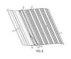
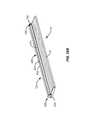
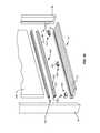
- FIGS. 7-11are various views of a threshold assembly having a plurality of spacers disposed between a threshold base substrate and a threshold cap for implementing a water management system in accordance with the present disclosure
- FIGS. 12 and 13are perspective views of a threshold base substrate for use in accordance with various aspects of the present disclosure.
- FIGS. 14-16are perspective views of a threshold assembly having drain holes and separate air inlets, according to one aspect of the present disclosure.
- FIG. 17is a perspective view a threshold assembly having a self-articulating threshold cap, according to one aspect of the present disclosure.
- FIG. 18is a side elevation view of a threshold assembly having a self-articulating threshold cap in an unbiased position, according to one aspect of the present disclosure
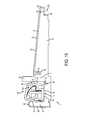
- FIG. 19is a side elevation view of a threshold assembly having a self-articulating threshold cap in a biased position, according to one aspect of the present disclosure
- FIGS. 20 and 21are perspective views of a self-articulating threshold cap, according to one aspect of the present disclosure.
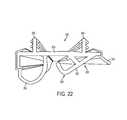
- FIG. 22is a perspective view of a door sweep, according to one aspect of the present disclosure.
- FIG. 23is a cross-sectional side elevation view of a threshold assembly having a self-articulating threshold cap not interacting with a door panel in an open position, according to one aspect of the present disclosure.
- FIG. 24is a cross-sectional side elevation view of a threshold assembly having a self-articulating threshold cap interacting with a door sweep of a door panel between a closed and an open position.
- FIG. 25Ais a perspective view of another embodiment of the threshold of the present disclosure with door jamb elements shown.
- FIG. 25Bis a perspective view of the threshold of FIG. 25A with the door jamb elements removed.
- FIG. 26is an exploded view of the threshold of FIG. 25A .
- FIG. 27is a cross-sectional side elevation view of the threshold of FIG. 25 in use with another embodiment of a door sweep according to the present disclosure.
- FIGS. 1-6each illustrate an entryway system 10 having a threshold assembly 11 including a threshold substrate 12 , which, in some instances, may be a unitarily molded plastic workpiece.
- the threshold substrate 12may be configured to define a longitudinally extending, upwardly open, sill channel 13 .
- the sill channel 13is flanked along its outside edge by a first channel wall 14 and along its inside edge by a second channel wall, i.e. nosing 15 .
- the first channel wall 14 and the nosing 15form the outside and inside walls, respectively, of the sill channel 13 .
- the sill channel 13can be sized to receive a threshold cap 100 (self-adjustable (see FIG. 1 ); non-adjustable (see FIG. 3 ); or vertically adjustable (see FIGS.
- the threshold substrate 12preferably is made of a deterioration resistant material, but may be made of any other material with appropriate support such as, for example, wood. In some instances, the threshold substrate 12 may be formed by a traditional injection molding process, or by an extrusion process.
- the term “threshold cap”refers to any element that substantially underlies the end of a door panel, when the door is closed. In embodiments that include a nosing and a dam, the threshold cap bridges the gap between the nosing and the dam of a threshold. Also, a threshold cap is formed of a rigid material providing a portion of the tread (the portion that is walked on and over) of the threshold, and is not made from covered foam as commonly found in weatherstrips.
- a nosing strip 16may be attached to an inside edge 17 of the sill channel 13 so as to extend upwardly therefrom over the nosing 15 .
- the nosing strip 16may extend across the sill channel 13 to cover a floor 18 thereof.
- a downwardly projecting nosing barbed tab 19can be positioned and configured to be snapped into place within a nosing attachment slot 20 to hold the nosing strip 16 securely in place within the sill channel 13 .
- a decking cover plate 21may be attached with appropriate means (e.g., mechanical, adhesive, etc.) to the threshold substrate 12 and forms an upper tread surface 22 of the threshold assembly 11 .
- the decking cover plate 21may include an upstanding decking dam 23 that extends upward from the first channel wall 14 to provide a water entry barrier that reduces the amount of water directly entering the sill channel 13 .
- the decking cover plate 21may have a contoured outside edge portion 24 (see FIGS. 14-19 ) configured to fit over the compatibly contoured forward edge 25 of the threshold substrate 12 .
- a downwardly projecting barbed decking tab 26may be formed along an underside surface 27 of the decking cover plate 21 and may be positioned and configured to be snapped into place within a decking attachment slot 28 to hold the decking cover plate 21 securely in place on the threshold substrate 12 .
- the threshold assemblies 11 of FIGS. 1-6have discrete components (e.g., the threshold substrate 12 , the decking cover plate 21 , and the nosing strip 16 ), it will be understood that this is not a limitation of the disclosure. That is, in some embodiments, the threshold assembly 11 can be formed completely from an aluminum extrusion, can be formed completely from an extruded or injection molded plastic material, or may be a combination thereof.
- the particular construction of the threshold assembly 11 illustrated in FIGS. 1-6is chosen because it is a common construction and because it serves well to illustrate the present disclosure. Those of skill in the art will understand, however, that a variety of threshold assembly constructions may well be used without departing from the spirit of the present disclosure.
- the elongated threshold cap 100is disposed in and projects upwardly from the upwardly open sill channel 13 .
- the threshold cap 100may be formed of single or multiple materials or components, wherein such suitable materials may include wood, plastic, a composite, or another appropriate material.
- the threshold cap 100is positioned to underlie a closed door panel 200 mounted in an entryway that includes the threshold assembly 11 .
- an array of vertical adjustment screw mechanisms 29may be provided for selectively and manually adjusting the height of the threshold cap 100 such that the threshold cap 100 sealingly engages a door sweep 300 mounted to a bottom edge 201 of a closed door panel 200 to form a seal between the bottom edge 201 of the door panel 200 and the threshold cap 100 .
- a door sweep 300can be formed of multiple components.
- a gap 30may be formed between the forward cap edge 31 of the threshold cap 100 and an inside surface 32 of the first channel wall 14 that defines an outside wall of the sill channel 13 .
- the gap 30may be in the range of about 0.08 inches (2.03 mm) to about 0.20 inches (5.08 mm) between the forward cap edge 31 and the inside surface 32 .
- a common dimension of the gap 30 in the threshold assembly 11may be about 0.14 inches (3.55 mm). Since the gap 30 is exposed to the elements on the outside of a building structure, it can afford the opportunity for rainwater to leak or seep into the upwardly open sill channel 13 and ultimately to the sub floor upon which the threshold assembly 11 rests.
- prior threshold assemblieshave attempted to provide a watertight barrier within or otherwise about the gap 30 , using sealing provisions, such as, for example, weatherstripping, flexible foam tape, etc., to prevent water from entering the sill channel 13 .
- sealing provisionssuch as, for example, weatherstripping, flexible foam tape, etc.
- prior threshold assembliesintend to prevent water from entering the interior of the building structure by attempting to plug all possible water entry points.
- thisis difficult to achieve and such sealing provisions typically allow at least some incidental water to seep or otherwise leak into the sill channel 13 .
- Such prior threshold assembliesmay thus provide drain systems that attempt to remove the incidental water from the sill channel 13 .
- such prior drain systemsmay only be capable of handling minimal amounts of water (i.e., incidental water that has leaked through the seal and into the sill channel).
- prior threshold assembliesmay not be equipped to handle non-incidental water (i.e., water that is naturally allowed to flow or otherwise enter the sill channel, rather than just minimally leak or seep into the sill channel).
- non-incidental wateri.e., water that is naturally allowed to flow or otherwise enter the sill channel, rather than just minimally leak or seep into the sill channel.
- such prior threshold assembliesmay have not envisioned allowing such non-incidental water to enter the threshold assembly.
- aspects of the present disclosureseek to allow non-incidental water to enter the threshold assembly 11 and then appropriately manage such non-incidental water. That is, the entryway system 10 of the present disclosure is configured to allow water to enter the sill channel 13 on the exterior of any sealing provisions and then manages the water and provides an avenue for water drainage out of the threshold assembly 11 . As such, the gap 30 is not entirely filled or otherwise entirely protected with a sealing mechanism(s) and is, instead, allowed to remain at least partially open-ended to receive non-incidental water therein.
- the present disclosureaccepts that at least some water will enter the threshold assembly 11 regardless of the attempted sealing of the gap 30 , and, as such, the present disclosure provides a water management system that allows non-incidental water into the threshold assembly 11 and then appropriately manages the water out thereof.
- some aspects of the present disclosureare directed to providing an unobstructed water entry path from the gap 30 to the exterior of a building structure.
- water entry barrier provisionse.g., flange 304 , decking dam 23 , fin 301 (see FIG. 6 )
- such provisionsdo not obstruct the water entry path and instead may, in some instances, only assist in defining the water entry path.
- sealing provisionse.g., fin 301 (see FIGS. 2-4 ) may be provided wherein the water leaks or otherwise seeps through the sealing provision and into the sill channel 13 via the gap 30 .
- aspects of the present disclosuremay provide the gap 30 as partially or entirely unobstructed such that water may flow directly into the sill channel 13 .
- the threshold cap 100may be positioned or secured toward the nosing 15 such that the gap 30 is provided between the threshold cap 100 and the first channel wall 14 .
- Appropriate securement or fastening mechanismsmay be provided for ensuring that the threshold cap 100 maintains its spacing from the first channel wall 14 to maintain the gap 30 . That is, the threshold cap 100 may be secured toward the nosing 15 so as to maintain the gap 30 .
- one or more spacers 33may be positioned within the gap 30 to maintain the gap 30 between the forward cap edge 31 of the threshold cap 100 and an inside surface 32 of the first channel wall 14 .
- the spacers 33are spaced apart from each other along a length of the sill channel 13 spanning an entryway, as shown in FIGS. 7-11 .
- the spacers 33may define a spacer channel 34 ( FIGS. 1-6 ) configured to receive a portion of the threshold cap 100 (e.g., a cap leg 101 of a front wall 106 of the threshold cap 100 ) for securing the spacers 33 within the sill channel 13 .
- the spacers 33may be disposed between the forward cap edge 31 of the threshold cap 100 and the inside surface 32 of the first channel wall 14 to maintain the gap 30 . As such, water may enter the sill channel 13 between the spacers 33 . That is, since the spacers 33 do not extend along the length of the sill channel 13 to fully fill the gap 30 , there are formed openings 35 between the spacers 33 that allow water to enter the sill channel 13 . In this regard, portions of the gap 30 may be left unfilled such that no sealing mechanism is provided between the threshold cap 100 and the first channel wall 14 .
- a sealing provisione.g., a fin 301
- the door sweep 300may limit the amount of water allowed to unimpededly enter the sill channel 13 , as shown in FIGS. 2-4 .
- the decking dam 23may provide a similar function (i.e., providing at least some impedance to water entry into the threshold assembly 11 ).
- a single spacer 33 of unitary constructionmay be provided and extended partially or entirely along the length of the threshold assembly 11 , wherein the spacer 33 itself may define one or more vertical slots (not shown) extending therethrough or otherwise defined thereby that allow the water to enter the sill channel 13 .
- the spacers 33may be of various configurations, as illustrated in FIGS. 1-6 .
- the specific configuration of the spacer 33may typically depend upon the type of threshold cap 100 incorporated into the threshold assembly 11 .
- the spacer 33may interlock or otherwise securely engage the threshold cap 100 in an interference or snap fit.
- the spacer 33may define a spacer channel 34 configured to receive a portion of the threshold cap 100 such as, for example, the cap leg 101 .
- the spacer 33may be configured to accommodate the vertical adjustment screw mechanisms 29 associated with the vertically adjustable threshold cap 100 (FIGS. 2 and 4 - 6 ).
- the spacer 33may include one or more spacer walls 56 capable of interacting with various portions of the threshold cap 100 .
- the spacer 33may extend substantially entirely along the floor 18 of the sill channel 13 between the first channel wall 14 and the nosing 15 .
- the threshold substrate 12is configured to direct the water from the sill channel 13 out of the threshold assembly 11 via a path that causes the water to eventually exit via one or more drain holes 36 (i.e., weep holes). More specifically, the water is directed out of the sill channel 13 through one or more drain channels 37 defined by the first channel wall 14 .
- the spacers 33may be offset from the drain channels 37 such that the water can flow from the sill channel 13 into the drain channels 37 according to the corresponding drain path.
- the watermay then be directed out of the drain holes 36 via gravity flow due to a substrate floor 38 of the threshold substrate 12 being downwardly sloped from the sill channel 13 toward the forward edge 25 of the threshold substrate 12 .
- FIGS. 10-13illustrate a threshold substrate 12 for installation in a threshold assembly 11 according to the present disclosure, where the threshold substrate 12 may comprise molded plastic.
- the threshold substrate 12is formed with the forward edge 25 , a back edge 39 , and a pair of side edges 40 , 41 .
- the sill channel 13is defined adjacent and along the back edge 39 of the threshold substrate 12 for receiving and holding the threshold cap 100 .
- the sill channel 13is bounded along the back edge 39 of the threshold substrate 12 by the nosing 15 .
- An array of spaced apart support walls 42extend from the first channel wall 14 proximate to the forward edge 25 of the threshold substrate 12 .
- the decking cover plate 21may be snapped or otherwise secured in place on the threshold substrate 12 covering and being supported by the support walls 42 thereof.
- the first channel wall 14 , the support walls 42 , the forward edge 25 , and the side edges 40 , 41cooperate to form a plurality of chambers 43 that, in some instances, may be continuously connected. That is, as shown in FIG. 10 , the support walls 42 do not extend to the forward edge 25 of the threshold substrate 12 . In this manner, the drain holes 36 may be positioned at opposing side ends of the threshold substrate 12 . In some instances, the chambers 43 may be closed such that water cannot flow from one chamber 43 to another. In such instances, each chamber 43 may include a corresponding drain hole 36 for permitting removal of water therefrom. A deflector wall 44 may be provided so as to direct water toward the drain holes 36 . Additional back pressure walls 42 A, 42 B assist in preventing water inflow caused by back exterior pressure.
- the drain channels 37which communicate with the sill channel 13 and the drain holes 36 , form a water management system for the threshold assembly 11 . More specifically, rain water that may collect in the sill channel 13 via the gap 30 is channeled away from the sill channel 13 by flowing to the forward edge 25 of the threshold substrate 12 , into the drain channels 37 , through the chambers 43 , and out the drain holes 36 . In this manner, the non-incidental rainwater is appropriately managed such that there is no path for water to leak beneath the threshold assembly and rot or otherwise deteriorate the subfloor upon which it rests and all water is drained to the forward edge 25 of the threshold assembly 11 and out thereof.
- the outside edge portion 24 of the decking cover plate 21fits over the forward edge 25 of the threshold substrate 12 .
- the forward edge 25 of the threshold substrate 12may define a lip 45 extending beyond a forward wall 46 of the threshold substrate 12 , which may be substantially perpendicular to the substrate floor 38 ( FIGS. 11-12 ).
- the outside edge portion 24 of the decking cover plate 21may be correspondingly configured to mate with the lip 45 , such as, for example, the outside edge portion 24 having a U-shaped profiled configured to wrap about the lip 45 .
- the decking cover plate 21terminates above the ground surface such that the drain holes 36 (as defined by the forward wall 46 of the threshold substrate 12 ) are not covered thereby. That is, the outside edge portion 24 does not extend the entire height of the forward wall 46 so as to leave a portion thereof uncovered.
- Such a configurationeliminates the need to provide or otherwise define corresponding drain holes 36 in the decking cover plate 21 .
- one or more air inlets 50may be provided in addition to and separate from the drain holes 36 .
- the air inlets 50allow air to enter the chambers 43 defined, for example, between the threshold substrate 12 and the decking cover plate 21 .
- the forward wall 46 of the threshold substrate 12may at least partially define the air inlets 50 (e.g., slots) at an upper end 47 thereof for allowing air to enter the chambers 43 .
- the one or more air inlets 50may be provided in an elevated arrangement with respect to the drain holes 36 . In such a configuration, the water may exit the threshold assembly 11 through the drain holes 36 and not through the air inlet(s) 50 .
- the forward wall 46may be injection molded with recesses that define the air inlets 50 .
- the air inlets 50may extend from a vertical surface 48 of the forward wall 46 and over a chamfered portion 55 and a top surface 49 of the forward edge 25 , such that the decking cover plate 21 is flush against the top surface 49 of the forward edge 25 except at the recessed air inlets 50 . That is, the decking cover plate 21 cooperates with the forward wall 46 and forward edge 25 of the threshold substrate 12 to form the air inlets 50 , wherein the decking cover plate 21 provides an upper barrier.
- Such separate air inlets 50 and drain holes 36provide advantages over prior art threshold assemblies, which have drain holes that provide both an exit for water and an inlet for air to enter the threshold assembly 11 for equalizing air pressure therein.
- the drain holestypically are used not only to provide an exit for water, but to also allow air to enter the threshold assembly for equalizing air pressure therein.
- such configurationstypically allow air to enter the drain holes to the detriment of allowing water to exit therefrom.
- allowing air to enter only through the drain holescan create a bubbling effect.
- aspects of the present disclosureprovide air inlets 50 separate from the drain holes 36 , which allows air to enter the chambers 43 via a mechanism other than the drain holes 36 .
- the threshold assembly 11may include a self-articulating or self-adjusting threshold cap 100 . That is, one aspect of the present disclosure is a self-articulating threshold cap 100 capable of self-adjusting to sealingly interact with the underside of the door panel 200 or otherwise with the door sweep 300 attached to the underside of the door panel 200 . Self-adjusting refers to the ability for the threshold cap 100 to change height without manual intervention. In most cases, this self adjustment provides a change in the vertical displacement of the threshold cap 100 relative to the threshold assembly 11 .
- the threshold cap 100may self-bias against the door panel 200 to maintain contact therewith, regardless of settling of a building or other cause that creates additional or reduced space between the threshold cap 100 and the door panel 200 or door sweep 300 .
- biasor “biasing” is defined as exerting force in a particular direction.
- the bias of the threshold cap 100causes the forming of a sealing barrier when door is closed. This barrier is formed regardless of the differences in spacing that might occur between these two elements.
- prior threshold capsthat are fixed or otherwise manually adjustable in a vertical direction using, for example, vertical adjustment screw mechanisms 29 (see FIGS. 2-6 ).
- the threshold cap 100may be configured for removal and replacement within a threshold assembly 11 either before or after installation thereof in an entryway.
- the threshold cap 100may include a mechanism, integral or otherwise, causing it to remain in contact with the door panel 200 as intended.
- the threshold cap 100is not manually adjusted, but instead may be displaced by the movement of the mating door panel 200 or the door sweep 300 .
- the threshold cap 100may be integrally formed and may be constructed from a plastic or polymeric material using, for example, an extrusion process. The material of construction of the threshold cap 100 may have a hinge feature that allows the threshold cap 100 to inherently bias against the door panel 200 when in contact therewith.
- the threshold cap 100may be formed of a polymeric material that permits at least a portion thereof to flex or otherwise deflect in accordance with the structural aspects of the present disclosure.
- the threshold cap 100may include an integral feature causing a portion thereof to tend to stay in a position biased toward the door panel 200 or the door sweep 300 .
- the threshold cap 100may include supplemental biasing mechanisms used to assist a portion of the threshold cap 100 to tend to stay in an upward position (e.g., a biasing spring 51 ).
- the threshold cap 100may include a rigid articulating top portion 102 having a continuous surface 103 capable of interacting with the door panel 200 or the door sweep 300 .
- the threshold cap 100may include a stationary body comprising a bottom support wall 104 , a rear wall 105 and a bottom support wall 106 in a hinged relationship with the rigid articulating top portion 102 .
- the bottom support wall 104is capable of being disposed within the sill channel 13 to engage the floor 18 thereof.
- the rear wall 105may extend perpendicularly from the bottom support wall 104 .
- the rear wall 105may include a projection 114 capable of interacting with the nosing 15 or the nosing strip 16 (when provided) to form a sealing barrier therewith.
- the front wall 106may depend from the bottom support wall 104 or otherwise be connected thereto via, for example, an arcuate portion 113 , and at least a portion of the front wall 106 may be substantially perpendicular to the bottom support wall 104 .
- the front wall 106may include an extension, such as, for example, the cap leg 101 , configured to be securely received within the spacer channel 34 .
- the articulating top portion 102extends from the front wall 106 .
- the articulating top portion 102is configured to self-bias against the underside of the door panel 200 or the door sweep 300 when the door panel 200 is in the closed position.
- the articulating top portion 102may include a top wall 107 and a locking wall 108 extending substantially perpendicular to the top wall 107 .
- the area of the articulating top portion 102 that is proximate to the intersection of the top wall 107 and the locking wall 108forming the uppermost portion.
- the threshold cap 100may further include an intermediate wall 109 disposed between the rear wall 105 and the front wall 106 .
- the intermediate wall 109acts to constrain the articulating top portion 102 .
- the intermediate wall 109may include a first leg 110 and a second leg 111 .
- the first leg 110may extend perpendicularly from the bottom support wall 104 .
- the second leg 111may depend perpendicularly from the first leg 110 toward the rear wall 105 .
- the locking wall 108may extend between the rear wall 105 and the second leg 111 .
- the locking wall 108may have a hook portion 112 configured to interact with the second leg 111 to prevent the locking wall 108 from advancing therepast, thereby limiting the upward travel of the articulating top portion 102 .
- a cap leg 101may be provided for being received within the spacer channel 34 such that each spacer 33 is maintained within the sill channel 13 . It is noted that the described legs, walls, and portions of the threshold cap 100 substantially extend along the
- FIG. 23illustrates one aspect of a threshold assembly 11 according to the present disclosure in which the door panel 200 is in an open position, wherein the threshold cap 100 is not interacting with the door sweep 300 .
- the self-articulating threshold cap 100may include the biasing spring 51 or other biasing mechanism configured to bias the articulating top portion 102 of the threshold cap 100 in an upwardly position for interacting with the door sweep 300 .
- the biasing spring 51 or other biasing mechanismmay be disposed within a cavity 115 generally defined by the threshold cap 100 and extending along the length thereof.
- the cavity 115may be defined by the bottom support wall 104 , the arcuate portion 113 , the front wall 106 , the intermediate wall 109 , and the articulating top portion 102 .
- FIG. 24illustrates the door panel 200 in a partially closed position, wherein the door sweep 300 has started to engage and interact with the threshold cap 100 .
- the door sweep 300interacts with the threshold cap 100 so as to force the top portion 102 thereof downward such that at least a portion of the door sweep 300 can advance therepast. More particularly, the door sweep 300 interacts with the top portion 102 to force the top wall 107 downward from an inclined position to an orientation substantially parallel to the bottom support wall 104 . In this manner, the top portion 102 may move from a biased position to an unbiased position when interacting with the door panel 200 or the door sweep 300 .
- FIG. 1illustrates the door panel 200 in a closed position, wherein the door sweep 300 is entirely engaged with the threshold cap 100 along the length of the threshold assembly 11 .
- the rigid articulating top portion 102 of the threshold cap 100is biased upward toward the door panel 200 to sealingly interact with a resilient bulb 302 of the door sweep 300 to form a sealing barrier.
- an elementis resilient when, upon compression, the structure changes shape, and upon removal of compression, the structure substantially returns back to its original shape.
- at least one portion of the nosing strip 16may be configured to contact the threshold cap 100 along the length of the threshold assembly 11 so as to form an additional seal therewith.
- both the door sweep 300 and the nosing strip 16may be configured to contact the threshold cap 100 upon closing of the door panel 200 such that multiple sealing barriers are formed along the length of the threshold assembly 11 .
- the nosing strip 16which may be of extruded plastic with a wood grain or other appropriate appearance, may be snapped or otherwise attached into place covering the nosing 15 of the threshold substrate 12 .
- the nosing strip 16which is visible from the inside of a building structure, covers the nosing 15 of the threshold substrate 12 and hides any junctions between adjacent threshold substrates 12 .
- the nosing strip 16may include a nosing portion 52 , a nosing fin 53 , and a sill channel cover portion 54 .
- the nosing portion 52may extend about the nosing 15 of the threshold substrate 12 , from within the sill channel 13 to the back edge 39 of the threshold substrate 12 .
- a barbed tab 19 of the nosing strip 16may be configured to be received within the nosing attachment slot 20 so as to engage the threshold substrate 12 for anchoring thereto.
- the nosing fin 53may be flexible and capable of interacting with the locking wall 108 of the threshold cap 100 to form an additional seal along the length of the threshold assembly 11 .
- a resilient sealing provisione.g., resilient bulb 302
- the door sweep 300may sealingly contact the nosing strip 16 , and top wall 107 .
- the nosing strip 16may extend across the floor 18 of the sill channel 13 .
- the nosing strip 16may be used to extend across adjacent threshold substrates 12 , which interlock, for covering a seam formed between the adjacent threshold substrates 12 , as disclosed in U.S. Pat. No. 7,350,336 to Bennett, which is assigned to Endura Products, Inc. (also the assignee of the present disclosure), and which is hereby incorporated herein by reference in its entirety.
- the door sweep 300may be integral with or otherwise attached, secured or fixed to a bottom portion of the door panel 200 .
- the door panel 200includes an underside or bottom edge 201 with the door sweep 300 flush thereagainst.
- the door sweep 300may include a support wall 303 secured to the bottom edge 201 of the door panel 200 and extending along the width thereof.
- the door sweep 300may be attached to the door panel 200 using, for example, one or more door sweep barbs 306 (as shown in FIG. 22 ) capable of being received within corresponding door slots (not shown) defined by the door panel 200 .
- a flange 304 , an arm 305 , and the resilient bulb 302depend from the support wall 303 .
- the flange 304 and resilient bulb 302are preferably flexible, while arm 305 is preferably rigid. In some instances, all three may be integrally formed with the support wall 303 . While it is preferred that resilient bulb 302 be generally ovoid, other suitable shapes are possible, such as resilient fins. It should be understood that resilient bulb 302 extends the length of the door sweep 300 , but since the cross-sectional shape is bulb-like, it is described as a bulb.
- the flange 304may include a flexible seal fin 307 that fits between the door panel 200 and support wall 303 for sealing the joint between the door panel 200 and door sweep 300 , thus preventing water penetration along the joint.
- The, preferably rigid, arm 305can be configured to interact with the threshold cap 100 so as to force the articulating top portion 102 thereof in a substantially downward direction (toward the floor 18 of the sill channel 13 ) as the door panel 200 is moved to the closed position.
- the arm 305continues to maintain contact with the threshold cap 100 due to the upward biasing thereof by, for example, the biasing spring 51 , thereby forming a first seal along the length of the entryway system 10 .
- the arm 305interacts with the continuous surface 103 and compresses the articulating top portion 102 of the threshold cap 100 into an unbiased position.
- the arm 305may be constructed of any suitable material, such as, for example, a plastic material, and may be integrally formed with the support wall 303 .
- the arm 305may include an arm arcuate portion 308 and an inclined portion 309 , both configured to interact with the threshold cap 100 such that the threshold cap 100 is initially forced downward and then allowed to bias against the door sweep 300 .
- the inclined portion 309may be in a sloped configuration with respect to the support wall 303 such that the inclined portion 309 provides the initial contact between the door sweep 300 and the threshold cap 100 .
- the top portion 102 of the threshold cap 100rides along the inclined portion 309 , towards the arm arcuate portion 308 , so as to maintain contact therewith as the door panel 200 is moved to the closed position.
- the arm arcuate portion 308eventually contacts the top portion 102 and forces the top portion 102 downward to a lower position. As the arm arcuate portion 308 moves along the top wall 107 , while maintaining contact therewith due to the upward biasing of the threshold cap 100 , the top portion 102 moves upward away from the floor 18 and into sealing contact with the door sweep 300 upon the door being in a fully closed position.
- the resilient bulb 302may be configured to sealingly interact with the threshold cap 100 , thereby forming a second seal along the length of the entryway system 10 .
- the resilient bulb 302may also be capable of contacting the nosing strip 16 to form an additional sealing barrier along the length of the entryway system 10 , as shown in FIG. 1 .
- the door sweep 300 and the threshold cap 100when used together, provide a strong positive seal between the door panel 200 and the threshold assembly 11 .
- FIG. 25Ashows an entry system 10 disposed between door jambs 90 and below a door panel 200 .
- the bottom of the door panel 200includes one embodiment of a door sweep 600 .
- the entryway system 10includes one embodiment of a self articulating threshold cap 100 .
- FIG. 25Bshows the entryway system 10 of FIG. 25A having an exemplary embodiment of a threshold cap 100 comprising an upper cap 400 and at least one cap base 500 .
- a threshold cap 100comprising an upper cap 400 and at least one cap base 500 .
- Disposed adjacent to the ends of the upper cap 400may be side gaskets 700 .
- the side gaskets 700are sized to be accepted into the sill channel 13 .
- the side gaskets 700may be held in sealing contact with the ends of the upper cap 400 by a respective cap base 500 .
- the cap base 500is provided with an end wall 530 for supporting the side gasket 700 .
- the side gasket 700may be adhered to the end wall 530 .
- the end wall 530provides both a connection surface for the side gasket 700 but also provides a rigid structure capable of supplying the side gasket 700 and end of the upper cap 400 with constant pressure.
- the upper cap 400includes a rigid articulating top portion 402 , supported and biased upwardly by a hinge 420 .
- the upper cap 400also includes a dam cover 430 configured to seal with decking dam 23 (see FIG. 26 ) of decking cover plate 21 .
- a similar dam sealing portion 730may extend from the side gasket 700 to also cover the decking dam 23 and help prevent water intrusion.
- FIG. 26shows an exploded view of the elements of FIG. 25A .
- the upper cap 400 in this embodimentextends substantially the full width of the entryway system 10 .
- the upper cap 400is then supported by at least one cap base 500 disposed along the length of the upper cap 400 .
- a cap base 500 , 501is disposed proximate to each distal end of the upper cap 400 .
- at least one additional cap base 502is disposed along the central portion of the upper cap 400 to provide support thereto.
- the number of cap bases 500 , 501 , 502can be adjusted to provide sufficient support based on the length of the entryway system 10 .
- cap bases 500 , 501 , 502at intervals along the upper cap 400 provides a cap base 500 and upper cap 400 combination that is less expensive to produce relative to threshold cap 100 due to a reduction in the amount of material used.
- Some of the cap bases 500 , 501may be formed with an end wall 530 to support a side gasket 700 as discussed above.
- Other cap bases 502may have the side wall omitted in order to allow the cap base 502 to support the central portion of the upper cap 400 .
- the cap base 500is configured to house a biasing spring 451 configured to provide an additional upward biasing force to the rigid articulating top portion 402 .
- FIG. 27shows a cross sectional view of FIG. 26 through the cap base 500 , in combination with another embodiment of a door sweep 600 .
- the upper cap 400may be configured to interact with the door sweep 600 as shown in FIG. 27 or may alternatively interact with the door sweep 300 of FIG. 1 .
- the upper cap 400may include a rigid articulating top portion 402 capable of interacting with the door panel 200 , a first embodiment of a door sweep 300 (see FIG. 1 ), or a second embodiment of a door sweep 600 .
- the articulating top portion 402may include a top wall 407 and a locking wall 408 extending substantially perpendicular to the top wall 407 . The area of the articulating top portion 402 that is proximate to the intersection of the top wall 407 and the locking wall 408 forming the uppermost portion.
- the upper cap 400may include a front wall 406 . At least a portion of the front wall 406 is configured to be substantially parallel, and disposed adjacent to the first channel wall 14 and decking dam 23 . Extending outwardly and downwardly from near the top of the front wall 406 is a dam cover 430 . The dam cover 430 and the front wall 406 combine to form a first slot 432 . The first slot 432 is configured to accept the decking dam 23 therein, and for forming a sealing engagement therewith, to reduce or eliminate water intrusion between the decking dam 23 and the upper cap 400 . Extending inwardly and downwardly from the front wall 406 is a substantially L-shaped projection 434 .
- the L-shaped projection 434includes a projection first leg 436 extending in the interior direction and a projection second leg 438 extending downwardly from the projection first leg 436 , substantially parallel with the front wall 406 .
- the projection second leg 438may include one or more flexible barbs 440 .
- the rigid articulating top portion 402extends from the inner surface of the front wall 406 at a position above the L-shaped projection 434 .
- the articulating top portion 402particularly top wall 407 , connects to the front wall 406 with a resilient hinge 420 .
- the hinge 420provides the mechanism by which the top portion 402 is biased upwardly toward the door panel 200 or door sweep 300 , 600 .
- the hinge 420may be a living hinge comprised of an area of reduced thickness of the same polymeric material as the top portion 402 , the front wall 406 , the l-shaped projection 434 and dam cover 430 .
- an optional biasing spring 451may be disposed under the articulating top portion 402 .
- the hinge 420may be comprised of a separate resilient material disposed between the top wall 407 and the front wall 406 as shown in FIG. 27 .
- the resilient materialcan be extruded and set to bias the articulating top portion 402 upwardly relative to the front wall 406 .
- the resilient materialcan be co-extruded with the articulating top portion 402 and the front wall 406 to form the self-articulating upper cap 400 .
- the hinge 420 of FIG. 25Bcan also apply to the self-articulating threshold cap 100 of FIGS. 1 , 23 and 24 . Providing the resilient material of the hinge 420 along the full length of the upper cap 400 is preferred.
- the resilient materialwill be able to provide a biasing force across the entire length of the rigid articulating top portion 402 .
- Some prior art capshave discrete springs spaced along the cap and providing discrete point forces to the cap. Application of only point forces means the prior art cap is less able to compensate for differences in spacing between the door panel and the cap, at locations between point force locations.
- the top portion 402will have an increased ability to maintain a seal with the door sweep 600 even if the gap between the door bottom edge 201 and the threshold assembly 11 is inconsistent along the length of the upper cap 400 .
- each of the cap bases 500 , 501 (see FIG. 26 ), 502is capable of being disposed within the sill channel 13 to reside on the floor 18 thereof.
- Each cap base 500 , 501 , 502comprises a bottom wall 504 to be disposed along the floor 18 of the sill channel 13 .
- the nosing strip 16extends along the floor 18 of the sill channel 13
- the cap bases 500 , 501 , 502can be set upon the nosing strip 16 .
- the bottom wall 504connects to a back wall 505 to be disposed adjacent to the nosing 15 or nosing strip 16 .
- Each cap base 500 , 501 , 502defines a cavity 510 with an upward opening 511 .
- a portion of said opening 511is covered by a stop wall 512 .
- the cavity 510 of each cap base 500 , 501 , 502is configured to accept the locking wall 408 of the upper cap 400 .
- the locking wall 408may further include a hook portion 412 configured to interact with the stop wall 512 to prevent the locking wall 408 from advancing upwardly therepast, thereby limiting the upward travel of the articulating top portion 402 of the upper cap 400 .
- the stop wall 512acts as a vertical adjustment limiter for the rigid articulating top portion 402 . Providing the stop wall 512 properly positions the top portion 402 when the door panel 200 is in the open position. If this vertical limiter were removed, the top portion 402 would relax to a height that would impede the ability to close the door panel 200 since the top portion 402 would likely strike the door panel 200 , instead of first enacting with the door sweep 300 , 600 . If the top portion 402 alone had a relaxed position equal to the height of engagement with the stop wall 512 , the relative biasing force applied to the top portion 402 would decrease, reducing the available sealing force between the upper cap 400 and the door sweep 300 , 600 .
- Cap bases 500 , 501 , 502can be provided with stop walls 512 disposed at various heights relative to the bottom wall 504 .
- the stop walls 512may be provided with various thicknesses to achieve the same result.
- a door panel 200may sag such that the gap between the door bottom and the entryway system 10 is smaller adjacent to the latch side of the door than the hinge side of the door. In this situation, the door can “stick” or become difficult to open and close due to contact with the entryway system 10 .
- the upper cap 400would preferably have a decreased maximum height adjacent to latch side of the door. To provide the upper cap 400 with a decreased maximum height at the end adjacent the door latch while maintaining the full maximum height of the upper cap 400 at the opposite, hinged end, and thereby accommodating the difference in gap, the cap base 500 supporting the end of the upper cap 400 adjacent the door latch may be different from the cap base 501 supporting the opposite end of the upper cap 400 .
- the cap base 500 on the left distal endmay have a stop wall 512 that is relatively high or relatively thin to fill a standard margin at the hinge side of the door, while the cap base 501 on the right distal end may have a stop wall 512 that is relatively lower or thicker to fill a lower margin on the latch side of the door.
- Each cap base 500 , 501 , 502may further define a base channel 520 extending along the length thereof.
- the base channel 520is configured to accept the second leg 438 of the upper cap 400 .
- the second leg 438forms a friction fit within the base channel 520 . Therefore, the at least one cap base 500 holds the front wall 406 of the upper cap 400 within the sill channel 13 .
- insert second leg 438 into base channel 520Slide the cap base 500 relative to the upper cap 400 to position the cap base 500 in the proper location along the upper cap 400 , then snap the locking wall 408 down past the stop wall 512 .
- An optional biasing spring 451can be disposed under the top wall 407 of the upper cap 400 , and may be held in place by the cap bases 500 , 501 , 502 .
- the side gaskets 700can also be used in combination with any of the threshold caps 100 shown in FIGS. 1-6 .
- the side gaskets 700can be adhered to non-adjustable portions of the caps 100 or adhered to a door jamb or mullion disposed at the end of the entryway system 10 .
- the side gaskets 700may be those described in a co-pending application Ser. No. 13/761,709 filed Feb. 7, 2013 and having the same inventors as the instant disclosure. The co-pending application is incorporated herein by reference.
- the articulating upper cap 400may interact with another exemplary embodiment of a door sweep 600 .
- the door sweep 600may be integral with or otherwise attached, secured or fixed to a bottom portion of the door panel 200 .
- the door panel 200includes an underside or bottom edge 201 with the door sweep 600 flush thereagainst.
- the door sweep 600may include a support wall 603 secured to the bottom edge 201 of the door panel 200 and extending along the width thereof.
- the support wall 603may be partially adhered to the door bottom using a strip of caulk applied along the exterior portion and longitudinal ends of the support wall 603 .
- a front flange 604 , a resilient bulb 602 , a first projection 605 , and a second projection 610depend from the support wall 603 .
- the front flange 604 and resilient bulb 602are preferably flexible, while projections 605 , 610 are preferably rigid. In some instances, all four may be integrally formed with the support wall 603 , by, for example, co-extrusion. While it is preferred that resilient bulb 602 be generally ovoid, other suitable shapes are possible. It should be understood that resilient bulb 602 extends the length of the door sweep 600 , but since the cross-sectional shape is bulb-like, it is described as a bulb.
- the front flange 604may include a flexible seal fin 607 that fits between the door panel 200 and support wall 603 for sealing the joint between the door panel 200 and door sweep 600 , thus preventing water penetration along the joint.
- the first projection 605can be configured to interact with the threshold cap 100 ( FIG. 1 ) or upper cap 400 so as to force the articulating top portion 102 , 402 thereof in a substantially downward direction (toward the floor 18 of the sill channel 13 ) as the door panel 200 is moved to the closed position.
- the first projection 605may be constructed of any suitable material, such as, for example, a plastic material, and may be integrally formed with the support wall 603 .
- the first projection 605extends substantially the entire length of the door sweep 600 and is positioned adjacent to the front flange 604 .
- the first projection 605includes at least an inclined portion 608 extending downward and rearward relative to the support wall 603 .
- the inclined portion 608may be a sloped configuration with respect to the support wall 603 such that the inclined portion 608 provides the initial contact between the door sweep 600 and the threshold cap 100 or upper cap 400 of the second embodiment of the self-articulating threshold cap 100 .
- the top portion 102 , 402 of the threshold cap 100 , or upper cap 400rides along the inclined portion 608 .
- the inclined portion 608acts as a ramp to force the top portion 102 , 402 of the articulating threshold cap 100 , or upper cap 400 downward.
- the top portion 102 , 402will re-adjust in an upward direction.
- the second, preferably rigid, projection 610is an arm extending downward and rearward relative to the support wall 603 .
- the second projection 610can extend substantially the entire length of the door sweep 600 and is disposed adjacent to an outward side of the resilient bulb 602 .
- the second projection 610is configured to interact with the top portion 102 , 402 of the articulating threshold cap 100 , or upper cap 400 thereof to properly position the top portion 102 , 402 to be at the correct height for forming a seal with the resilient bulb 602 .
Landscapes
- Engineering & Computer Science (AREA)
- Civil Engineering (AREA)
- Structural Engineering (AREA)
- Building Environments (AREA)
Abstract
Description
Claims (16)
Priority Applications (7)
| Application Number | Priority Date | Filing Date | Title |
|---|---|---|---|
| US13/835,874US8991100B2 (en) | 2011-08-23 | 2013-03-15 | Door entryway system |
| US29/454,373USD722387S1 (en) | 2013-03-15 | 2013-05-09 | Articulating threshold cap |
| CA2842214ACA2842214C (en) | 2013-03-15 | 2014-02-07 | Door entryway system |
| US14/666,366US9371682B2 (en) | 2011-08-23 | 2015-03-24 | Door entryway system |
| US15/158,706US10066433B2 (en) | 2011-08-23 | 2016-05-19 | Door entryway system |
| US16/057,894US10407975B2 (en) | 2011-08-23 | 2018-08-08 | Door entryway system |
| US16/561,359US11193321B2 (en) | 2011-08-23 | 2019-09-05 | Door entryway system |
Applications Claiming Priority (2)
| Application Number | Priority Date | Filing Date | Title |
|---|---|---|---|
| US13/215,905US8522483B2 (en) | 2011-08-23 | 2011-08-23 | Door entryway system |
| US13/835,874US8991100B2 (en) | 2011-08-23 | 2013-03-15 | Door entryway system |
Related Parent Applications (1)
| Application Number | Title | Priority Date | Filing Date |
|---|---|---|---|
| US13/215,905Continuation-In-PartUS8522483B2 (en) | 2011-08-23 | 2011-08-23 | Door entryway system |
Related Child Applications (2)
| Application Number | Title | Priority Date | Filing Date |
|---|---|---|---|
| US29/454,373Continuation-In-PartUSD722387S1 (en) | 2013-03-15 | 2013-05-09 | Articulating threshold cap |
| US14/666,366ContinuationUS9371682B2 (en) | 2011-08-23 | 2015-03-24 | Door entryway system |
Publications (2)
| Publication Number | Publication Date |
|---|---|
| US20130199100A1 US20130199100A1 (en) | 2013-08-08 |
| US8991100B2true US8991100B2 (en) | 2015-03-31 |
Family
ID=48901673
Family Applications (5)
| Application Number | Title | Priority Date | Filing Date |
|---|---|---|---|
| US13/835,874ActiveUS8991100B2 (en) | 2011-08-23 | 2013-03-15 | Door entryway system |
| US14/666,366ActiveUS9371682B2 (en) | 2011-08-23 | 2015-03-24 | Door entryway system |
| US15/158,706Active2032-02-17US10066433B2 (en) | 2011-08-23 | 2016-05-19 | Door entryway system |
| US16/057,894ActiveUS10407975B2 (en) | 2011-08-23 | 2018-08-08 | Door entryway system |
| US16/561,359Active2032-02-26US11193321B2 (en) | 2011-08-23 | 2019-09-05 | Door entryway system |
Family Applications After (4)
| Application Number | Title | Priority Date | Filing Date |
|---|---|---|---|
| US14/666,366ActiveUS9371682B2 (en) | 2011-08-23 | 2015-03-24 | Door entryway system |
| US15/158,706Active2032-02-17US10066433B2 (en) | 2011-08-23 | 2016-05-19 | Door entryway system |
| US16/057,894ActiveUS10407975B2 (en) | 2011-08-23 | 2018-08-08 | Door entryway system |
| US16/561,359Active2032-02-26US11193321B2 (en) | 2011-08-23 | 2019-09-05 | Door entryway system |
Country Status (1)
| Country | Link |
|---|---|
| US (5) | US8991100B2 (en) |
Cited By (23)
| Publication number | Priority date | Publication date | Assignee | Title |
|---|---|---|---|---|
| US20150191964A1 (en)* | 2011-08-23 | 2015-07-09 | Endura Products, Inc. | Door entryway system |
| US20160145076A1 (en)* | 2014-11-20 | 2016-05-26 | Scott Akin | Elevator sill system |
| US9487992B2 (en) | 2014-11-26 | 2016-11-08 | Quanex Corporation | Threshold assembly for an entryway system |
| USD775367S1 (en) | 2015-05-20 | 2016-12-27 | Endura Products, Inc. | Door sweep |
| USD775366S1 (en) | 2015-05-20 | 2016-12-27 | Endura Products, Inc. | Door sweep |
| USD775368S1 (en) | 2015-05-20 | 2016-12-27 | Endura Products, Inc. | Door sweep |
| US9710686B2 (en) | 2015-09-30 | 2017-07-18 | Datalogic ADC, Inc. | Data collection system and method that detect electronic device displays via fresnel patterns |
| USD797309S1 (en)* | 2016-03-14 | 2017-09-12 | Endura Products, Inc. | Threshold cap |
| US9874054B2 (en) | 2015-05-20 | 2018-01-23 | Endura Products, Inc. | Entryway with articulating threshold |
| USD812772S1 (en) | 2016-12-21 | 2018-03-13 | Global Products International Group, Llc | Low dam outswing sill cap |
| USD820470S1 (en) | 2016-12-21 | 2018-06-12 | Global Products International Group, Llc | High dam outswing sill cap |
| US10077593B2 (en) | 2014-11-26 | 2018-09-18 | Quanex Homeshield Llc | Threshold assembly for an entryway system |
| US10202795B2 (en) | 2015-10-13 | 2019-02-12 | Endura Products, Inc. | Doorsill |
| USD873440S1 (en)* | 2018-04-25 | 2020-01-21 | Endura Products, Inc. | Threshold cap |
| USD875969S1 (en)* | 2015-05-20 | 2020-02-18 | Endura Products, Inc. | Threshold cap |
| US10783158B2 (en) | 2016-12-19 | 2020-09-22 | Datalogic IP Tech, S.r.l. | Method and algorithms for auto-identification data mining through dynamic hyperlink search analysis |
| USD903902S1 (en)* | 2015-05-20 | 2020-12-01 | Endura Products, Llc | Threshold cap |
| US10858881B2 (en) | 2018-04-25 | 2020-12-08 | Endura Products, Llc | Threshold and threshold cap |
| US11047165B1 (en)* | 2019-03-26 | 2021-06-29 | Jerry L. Monts de Oca | Durable entryway threshold |
| US11072969B2 (en) | 2018-09-11 | 2021-07-27 | Endura Products, Llc | Door sill system, apparatus and methods for a door assembly |
| US11085229B2 (en) | 2018-07-23 | 2021-08-10 | Endura Products, Llc | Threshold and threshold cap assembly |
| US20230027784A1 (en)* | 2021-07-26 | 2023-01-26 | Jeld-Wen, Inc. | Weatherstrip carrier that removably attaches to fenestration unit |
| US11732525B2 (en) | 2021-02-02 | 2023-08-22 | Endura Products, Llc | Door sill system, apparatus, and methods for a door assembly |
Families Citing this family (24)
| Publication number | Priority date | Publication date | Assignee | Title |
|---|---|---|---|---|
| US8813427B2 (en)* | 2012-05-17 | 2014-08-26 | Quanex Corporation | Threshold assembly having a rail and a drainage element |
| CA2846962C (en)* | 2013-03-15 | 2021-09-28 | Pemko Manufacturing Company, Inc. | Threshold |
| US20150096235A1 (en)* | 2013-10-09 | 2015-04-09 | Oded Eddy Rochman | Door sill assembly, door sill and kit therefor |
| US9562387B2 (en)* | 2014-04-24 | 2017-02-07 | Quanex Homeshield Llc | Door bottom system for an entryway system |
| US9097059B1 (en)* | 2014-05-01 | 2015-08-04 | Andersen Corporation | Draining sill and frame assembly incorporating the same |
| US20160215555A1 (en)* | 2015-01-23 | 2016-07-28 | Quanex Corporation | Sill Assembly for a Threshold System and a Method of Producing the Same |
| GB2543855A (en)* | 2015-11-02 | 2017-05-03 | William M Snape Mfg Services (Uk) Ltd | Flood seal arrangement |
| US10526839B2 (en) | 2016-01-29 | 2020-01-07 | Masonite Corporation | Method of installing an adjustable corner pad |
| US10494857B2 (en)* | 2016-10-11 | 2019-12-03 | Quanex Homeshield, Llc | Threshold assembly having a rail with a drainage wall defining a drainage passageway |
| US10100570B1 (en)* | 2017-03-27 | 2018-10-16 | Tejas Specialty Group, Inc. | Threshold gasket assembly |
| US10895103B2 (en) | 2017-04-13 | 2021-01-19 | Paul Boulos ALKHOURY | Modular threshold assembly |
| US10815721B2 (en)* | 2017-04-21 | 2020-10-27 | Endura Products, Llc | Entryway sealing spacer |
| CN109264556B (en)* | 2017-07-18 | 2021-10-26 | 富士达株式会社 | Door device of elevator |
| US10370891B2 (en)* | 2017-10-10 | 2019-08-06 | Kamran Farahmandpour | Adjustable threshold device |
| USD876671S1 (en)* | 2018-01-03 | 2020-02-25 | Mjb Wood Group, Llc | Door threshold assembly |
| US10612291B2 (en)* | 2018-01-12 | 2020-04-07 | Mjb Wood Group, Llc | Door threshold assembly |
| US20190264490A1 (en)* | 2018-02-28 | 2019-08-29 | Tru Tech Corporation | Self-draining threshold for exterior doorways |
| CN108533125B (en)* | 2018-04-02 | 2019-06-25 | 中国一冶集团有限公司 | A kind of installation method of energy conservation auxiliary frame antiseep |
| CA3066590C (en) | 2019-01-11 | 2022-02-15 | Pella Corporation | Sill systems for sliding fenestration units |
| USD949680S1 (en)* | 2019-05-03 | 2022-04-26 | George J. Partsch, IV | Protective device for an edge of a glass object |
| CN113623910A (en)* | 2020-05-08 | 2021-11-09 | 博西华电器(江苏)有限公司 | Refrigerator and beam for refrigerator |
| US20220090440A1 (en)* | 2020-09-23 | 2022-03-24 | Legacy Manufacturing LLC | Automatic Door Bottom With Intumescent Extended Drop |
| US11346147B2 (en)* | 2020-10-01 | 2022-05-31 | Solar Innovations Llc | Modular sill |
| US12091152B2 (en)* | 2022-06-09 | 2024-09-17 | Embraer S.A. | Aircraft door seals and lap joint junction seal assemblies thereof |
Citations (87)
| Publication number | Priority date | Publication date | Assignee | Title |
|---|---|---|---|---|
| US56046A (en) | 1866-07-03 | Improved weather-strip | ||
| US220460A (en) | 1879-10-07 | Improvement in water-proof thresholds | ||
| US313742A (en) | 1885-03-10 | Threshold | ||
| US435658A (en) | 1890-09-02 | Weather-strip | ||
| US582451A (en) | 1897-05-11 | James c | ||
| US600301A (en) | 1898-03-08 | Combined threshold and weather strip | ||
| US618013A (en) | 1899-01-17 | Threshold for doors | ||
| US1468958A (en) | 1921-03-19 | 1923-09-25 | Raymond W Champion | Weather seal for thresholds |
| US1795853A (en) | 1929-06-12 | 1931-03-10 | Glass Booker Hughe | Rainproof saddle for weather-strip exterior doors |
| US2108137A (en) | 1936-04-18 | 1938-02-15 | Philip R Oftedal | Threshold |
| US2129381A (en) | 1935-08-17 | 1938-09-06 | Oftedal | Threshold construction |
| US2202482A (en) | 1938-12-10 | 1940-05-28 | Maurice S Oftedal | Weather strip |
| US2663056A (en) | 1950-09-27 | 1953-12-22 | Walter H Hardgrave | Weatherstrip |
| US2696029A (en) | 1953-06-11 | 1954-12-07 | Lewis T Neff | Weather strip |
| US2728118A (en) | 1952-12-22 | 1955-12-27 | John M Gossen | Adjustable thresholds |
| US2818614A (en) | 1956-07-23 | 1958-01-07 | Jr Frank Lapka | Threshold |
| US3083420A (en) | 1960-04-21 | 1963-04-02 | Tinflow Lionel | Weather resistant door saddle |
| US3114180A (en) | 1962-03-12 | 1963-12-17 | Marvin W Riedl | Adjustable threshold structure |
| US3374579A (en) | 1966-04-29 | 1968-03-26 | Edsel B. Neff | Adjustable threshold |
| US3402512A (en) | 1966-05-31 | 1968-09-24 | Francis C. Peterson | Adjustable threshold |
| US3432966A (en) | 1967-04-28 | 1969-03-18 | Crane Plastics Inc | Combination interlock and weather seal strip arrangement for relatively slidable closure members |
| US3475886A (en) | 1967-06-21 | 1969-11-04 | Brewer & Co Ltd | Method of harvesting sugar cane |
| US3762100A (en) | 1971-09-24 | 1973-10-02 | Taylor Garage Doors Inc | Threshold and sill assembly |
| US3854246A (en) | 1971-09-13 | 1974-12-17 | Combustion Eng | Threshold weatherstrip |
| US3900967A (en) | 1974-07-26 | 1975-08-26 | Pease Co | Adjustable sill and threshold assembly |
| US3967412A (en) | 1975-09-17 | 1976-07-06 | Peachtree Doors, Inc. | Adjustable threshold |
| US4055917A (en) | 1975-10-14 | 1977-11-01 | Elixir Industries | Door and threshhold assembly |
| US4079550A (en) | 1977-01-17 | 1978-03-21 | Pease Company | Composite sill assembly |
| US4104830A (en) | 1977-07-11 | 1978-08-08 | Fred Eagle | Adjustable threshold |
| US4146995A (en) | 1975-06-02 | 1979-04-03 | Britt Robert E | Adjustable thresholds and methods of making and using the same |
| US4156325A (en) | 1977-10-21 | 1979-05-29 | Edgett Edgar I | Sill kit or assembly |
| US4213275A (en) | 1979-04-02 | 1980-07-22 | Oehmig Robert G | Threshold and door sealing structure |
| US4224766A (en) | 1979-05-21 | 1980-09-30 | Endura Products, Inc. | Threshold with flexible insulator |
| US4287684A (en) | 1979-08-15 | 1981-09-08 | General Products Company, Inc. | Threshold with adjustable weather seal |
| US4310991A (en) | 1979-09-26 | 1982-01-19 | Embossed Door Corporation | Door sealing system |
| US4352258A (en) | 1980-08-04 | 1982-10-05 | Pease Company | Adjustable sill and threshold |
| US4387535A (en) | 1981-12-07 | 1983-06-14 | Manco Tape, Inc. | Adjustable threshold assembly |
| US4411104A (en) | 1980-11-12 | 1983-10-25 | Lst Corporation | Inswing door bottom and sill assembly |
| US4447987A (en) | 1981-03-19 | 1984-05-15 | Decor Doors Manufacturing Ltd. | Adjustable threshold and sill assembly |
| US4447989A (en) | 1982-03-16 | 1984-05-15 | Minnesota Mining And Manufacturing Company | Adjustable weatherstrip assembly |
| US4513536A (en) | 1982-11-12 | 1985-04-30 | Donat Flamanc Inc. | Weather tight seal for the sill of a household door |
| US4525953A (en) | 1983-10-14 | 1985-07-02 | Stutzman Ellis D | Weather seal with wide range of flexure |
| US4625457A (en) | 1985-05-30 | 1986-12-02 | Avery Phillip E | Insulating member for double doors |
| US4628639A (en) | 1985-08-08 | 1986-12-16 | Schlegel Corporation | Window frame weatherseal for a motor vehicle |
| US4686793A (en) | 1986-06-23 | 1987-08-18 | Mills Norman J | Threshold |
| US4716683A (en) | 1985-05-13 | 1988-01-05 | Rolscreen Company | Door weatherstripping assembly |
| US4831779A (en) | 1988-08-31 | 1989-05-23 | Schlegel Corporation | Self-draining panel threshold combination |
| EP0327840A2 (en) | 1988-02-06 | 1989-08-16 | Firma F. Athmer Sophienhammer | Magnetic seal for the gap between a floor and a door |
| US5010690A (en) | 1990-04-14 | 1991-04-30 | Imperial Products, Inc. | Adjustable threshold assembly with water-tight seals |
| US5012614A (en) | 1989-11-22 | 1991-05-07 | Shea Gregory T | Blow-molded unitary thermoplastic threshold |
| US5018307A (en) | 1990-04-25 | 1991-05-28 | Schlegel Corporation | Self-draining threshold for an out-swinging door |
| US5067279A (en) | 1991-02-04 | 1991-11-26 | Rolscreen Company | Self draining door threshold |
| US5136814A (en) | 1991-05-09 | 1992-08-11 | Headrick Management Corporation | Draining door sill assembly with adjustable threshold cap |
| US5179804A (en) | 1991-10-31 | 1993-01-19 | Young Robert H | Self draining door sill assembly |
| US5426894A (en) | 1993-12-03 | 1995-06-27 | Headrick; J. Charles | Continuous sidelight sill with adaptable threshold caps |
| US5588266A (en) | 1993-12-03 | 1996-12-31 | Headrick; J. Charles | Continuous sidelight sill with adaptable threshold caps and removable paint shield |
| US5706607A (en) | 1994-09-17 | 1998-01-13 | Frey; Harry | Magnetic door seal |
| US5857291A (en) | 1996-12-20 | 1999-01-12 | Headrick Manufacturing Company | Astragal with integral sealing lock block |
| US5943825A (en) | 1998-08-26 | 1999-08-31 | Endura Products, Inc. | Entryway system and method |
| US6061967A (en) | 1999-01-19 | 2000-05-16 | Judds; Raymond E. | Overhead door sealing assembly |
| US6125584A (en) | 1994-12-29 | 2000-10-03 | Pemko Manufacturing Co. | Automatic door bottom |
| US6138413A (en) | 1996-12-12 | 2000-10-31 | Huron Window Corporation | Standardized framing section for closure wings |
| US6216395B1 (en) | 1999-02-08 | 2001-04-17 | Donald R. Kelly | Threshold protective cover |
| US6367201B1 (en) | 2000-03-10 | 2002-04-09 | Endura Products, Inc. | Width adaptable threshold assembly |
| US6371188B1 (en) | 1999-06-17 | 2002-04-16 | The Stanley Works | Doors assembly and an improved method for making a doors sill assembly |
| US20020194787A1 (en) | 2001-03-21 | 2002-12-26 | Bennett Joel S. | Threshold assembly with flexible watertight foam cap seal |
| USD488243S1 (en) | 2001-07-06 | 2004-04-06 | Andersen Corporation | Door sill portion |
| US6763639B2 (en) | 2000-07-10 | 2004-07-20 | Endura Products, Inc. | Threshold assembly with pre-fitted draining jamb boots and pre-fitted mull boots |
| US6789358B2 (en) | 2000-11-01 | 2004-09-14 | Endura Products, Inc. | Threshold assembly with unitary molded substrate and jamb boot subassembly |
| US20040200153A1 (en) | 2003-04-10 | 2004-10-14 | Haik Khanlarian | Modular composite sill for threshold |
| US20050210754A1 (en) | 2004-03-15 | 2005-09-29 | Imperial Products, Inc. | Adjustable threshold assembly |
| US20060053695A1 (en) | 2004-09-10 | 2006-03-16 | Palenske Grant A | Integrated adjustable threshold |
| US20060174545A1 (en) | 2005-02-09 | 2006-08-10 | Young Robert H | Banded door sill base and door sill assembly, and method of forming same |
| US7114293B2 (en) | 2004-11-17 | 2006-10-03 | Holm Industries, Inc. | Magnetic door sweep and magnetic threshold assembly |
| US20060283087A1 (en) | 2005-06-21 | 2006-12-21 | Baxter Stephen M | Automatic door bottom and sill assemblage |
| USD549850S1 (en) | 2006-03-21 | 2007-08-28 | Richard Perlman | Door threshold |
| US7263808B2 (en) | 2002-10-01 | 2007-09-04 | Premdor International, Inc. | Adjustable rail assembly for exterior door still assembly and components for the same |
| US20070227076A1 (en) | 2006-04-04 | 2007-10-04 | Therma-Tru Corp. | Entry system with water infiltration barrier |
| US7350336B2 (en) | 2001-05-29 | 2008-04-01 | Endura Products, Inc. | Continuous threshold assembly with modular interlocking substrate sections |
| US20080110100A1 (en) | 2006-11-09 | 2008-05-15 | Heppner Thomas J | Low profile, self-draining threshold assemblies |
| US20080229669A1 (en) | 2007-03-20 | 2008-09-25 | Endura Products, Inc. | Flip top adjustable threshold cap |
| US7472516B2 (en) | 2004-12-01 | 2009-01-06 | Quanex Corporation | Adjustable threshold assembly |
| US20090199486A1 (en) | 2008-02-12 | 2009-08-13 | Chad Wernlund | Doorway with anti-bubbling sill drain |
| US7600346B2 (en) | 2007-03-14 | 2009-10-13 | Quanex Corporation | Entryway system including a threshold assembly |
| US7669369B2 (en) | 2005-01-12 | 2010-03-02 | Michael Henry | Door threshold water return systems |
| USD638958S1 (en) | 2010-08-25 | 2011-05-31 | Endura Products, Inc. | Articulating threshold sill cap |
| US8074699B2 (en) | 2008-09-12 | 2011-12-13 | La Cantina Doors, Inc. | Zero step sill extruded flush threshold door seal system |
Family Cites Families (99)
| Publication number | Priority date | Publication date | Assignee | Title |
|---|---|---|---|---|
| US126014A (en) | 1872-04-23 | Improvement in weather-strips | ||
| US394864A (en) | 1888-12-18 | Weather-strip | ||
| US500885A (en) | 1893-07-04 | Weather-strip | ||
| GB189809888A (en) | 1898-04-29 | 1899-03-25 | William Montgomery Barger | Improvements in Thresholds and Weather Strips therefor. |
| US628278A (en) | 1899-02-20 | 1899-07-04 | Charles Mitsch | Storm-strip for doors. |
| US704295A (en) | 1900-07-09 | 1902-07-08 | Robert H Sterrett | Narrow-ware loom. |
| US704395A (en) | 1901-09-03 | 1902-07-08 | Charles R Sowden | Automatic threshold. |
| US1210535A (en) | 1915-06-18 | 1917-01-02 | Frank T Riley | Yielding joint-strip for thresholds. |
| US1595827A (en) | 1926-04-29 | 1926-08-10 | Frisque Victor | Adjustable threshold |
| US1883609A (en) | 1930-05-31 | 1932-10-18 | William J Dennis | Gasket |
| US1993506A (en) | 1933-10-02 | 1935-03-05 | Joseph F Fauner | Weatherproofing device |
| GB411361A (en) | 1933-10-27 | 1934-06-07 | Ernest Griffiths | Improvements in or relating to draught preventing devices |
| US2022408A (en)* | 1934-09-24 | 1935-11-26 | Gardner Wire Company | Metal weather strip |
| US2293292A (en)* | 1939-12-02 | 1942-08-18 | Monarch Metal Weatherstrip Cor | Weather strip |
| FR945217A (en) | 1944-04-07 | 1949-04-28 | Improvements to weather stripping devices applicable to doors | |
| US2630891A (en) | 1947-02-13 | 1953-03-10 | Zitomer Abe | Window structure |
| US2579875A (en) | 1950-05-20 | 1951-12-25 | Stanko Lloyd | Door threshold |
| US2718677A (en)* | 1954-02-23 | 1955-09-27 | Elder Cornell Jr W | Threshold and door sealing construction |
| US2853749A (en)* | 1956-05-24 | 1958-09-30 | United Ind Inc | Threshold |
| US2949651A (en) | 1958-01-20 | 1960-08-23 | Victor Jay Hill | Weather stripping |
| US3250040A (en) | 1964-05-22 | 1966-05-10 | Boyd Aluminum Mfg Co | Adjustable door sweep |
| US3273287A (en) | 1964-06-29 | 1966-09-20 | Pease Woodwork Company Inc | Sill and threshold assembly |
| US3378958A (en) | 1966-09-21 | 1968-04-23 | Goodrich Co B F | Extrusions having integral portions of different stiffness |
| US3448543A (en) | 1968-02-20 | 1969-06-10 | Stanley Works | Weatherstrip for door sill and door assembly employing same |
| US3475866A (en) | 1968-02-28 | 1969-11-04 | Bergiton Johansen | Adjustable threshold |
| US3521404A (en) | 1968-05-27 | 1970-07-21 | Marquette Components Mfg Corp | Threshold construction |
| US3690037A (en) | 1970-01-14 | 1972-09-12 | Taylor Garage Doors Inc | Prefabricated door and frame assembly |
| DE2135919A1 (en) | 1971-07-14 | 1973-02-01 | Ernst Paul Ossig | SELF-CLOSING ALL-WEATHER SEALING FITTING |
| US3962828A (en) | 1974-08-01 | 1976-06-15 | Combustion Engineering, Inc. | Adjustable framing member |
| JPS5531185Y2 (en) | 1975-08-18 | 1980-07-24 | ||
| US4034511A (en) | 1975-12-12 | 1977-07-12 | Pease Company | Weather stripping construction for metal covered door |
| US4074464A (en) | 1976-10-04 | 1978-02-21 | Mccay Dariel | Adjustable threshold |
| US4114319A (en) | 1977-12-23 | 1978-09-19 | Peachtree Doors, Inc. | Bottom sweep and rail unit for foam-filled doors |
| US4185417A (en) | 1978-09-05 | 1980-01-29 | General Products Company, Inc. | Weather seal apparatus |
| USD270185S (en) | 1981-08-28 | 1983-08-16 | Wooten Ronald E | Weatherseal molding |
| USD279409S (en) | 1982-11-23 | 1985-06-25 | Allen Jr George A | Combined smoke gasket and intumescent expanding seal device for sliding elevator doors and the like |
| US4565033A (en)* | 1984-05-09 | 1986-01-21 | Lionel Tinfow | Threshold having a vertically adjustable flexible weatherstrip |
| JPS6185690A (en) | 1984-09-29 | 1986-05-01 | Sony Corp | Video tape recorder |
| US5056263A (en) | 1991-01-17 | 1991-10-15 | The Stanley Works | Self-positioning and self-locking door sweep and door assembly therewith |
| US5150544A (en) | 1991-08-28 | 1992-09-29 | Schlegel Corporation | Magnetically mounted door sweep |
| US5174065A (en) | 1992-01-08 | 1992-12-29 | The Stanley Works | Door sweep with face sealing element |
| DE69228948T2 (en) | 1992-01-23 | 1999-12-02 | Ian Thomas Howe | DRAFT AND WATER DEFLECTORS FOR DOORS |
| US5214880A (en) | 1992-04-03 | 1993-06-01 | Emco Enterprises, Inc. | Door edge construction |
| JPH0781465B2 (en) | 1992-06-09 | 1995-08-30 | ナショナル住宅産業株式会社 | Sash mounting structure |
| JP3125197B2 (en) | 1992-06-27 | 2001-01-15 | 大和ハウス工業株式会社 | Closure device for floor gap at floor bottom |
| US5230181A (en) | 1992-12-21 | 1993-07-27 | Imperial Products, Inc. | Adjustable threshold assembly with water-impervious seal |
| US5375376A (en) | 1993-01-21 | 1994-12-27 | Crane Plastics Company Limited Partnership | Polymeric sealing/spring strip and extrusion method of producing same |
| USD354572S (en) | 1993-03-08 | 1995-01-17 | Headrick J Charles | Combined door sill and threshold |
| US5524391A (en) | 1995-03-20 | 1996-06-11 | Imperial Products, Inc. | Adjustable threshold assembly with water-tight seal |
| GB2302898B (en) | 1995-07-05 | 1999-02-17 | Lin Chen Yi | Door sealing mechanisms |
| JPH1037626A (en) | 1996-07-19 | 1998-02-10 | Denki Koji Nishikawagumi:Kk | Door sill structure and door |
| JPH10102937A (en) | 1996-09-26 | 1998-04-21 | Yamaha Living Tec Kk | Door structure of bathroom |
| JPH10110579A (en) | 1996-10-07 | 1998-04-28 | Jiyuuken Sangyo:Kk | Door device |
| US5887392A (en) | 1997-02-10 | 1999-03-30 | Amesbury Group, Inc. | Window jambliner with removably attached members for biasing and sealing |
| US6006375A (en) | 1997-10-10 | 1999-12-28 | Cfm, Inc. | Removable threshold |
| GB9809868D0 (en) | 1998-05-08 | 1998-07-08 | Easy Care Prod Ltd | Portable hoist arrangement |
| DE19932332C2 (en) | 1999-07-10 | 2003-10-09 | Bautec Sp Zo O | Door threshold with a threshold body |
| US6345477B1 (en) | 2000-03-24 | 2002-02-12 | Tt Technologies, Inc. | Door sill assembly having adjustable threshold |
| US6374545B1 (en) | 2000-05-03 | 2002-04-23 | The Stanley Works | Snap-on door sweep |
| US6484446B2 (en) | 2001-03-15 | 2002-11-26 | Robert H. Young | Door sill assembly having improved weatherseal |
| JP2003013672A (en) | 2001-07-04 | 2003-01-15 | Norimitsu Sukejima | Water cut-off structure of door |
| US20030005644A1 (en) | 2001-07-06 | 2003-01-09 | Reithmeyer Joseph Guy | Adjustable door with sealed threshold, hinge and frame |
| US7207143B2 (en) | 2001-11-08 | 2007-04-24 | Pergo (Europe) Ab | Transition molding and installation methods therefor |
| US7140154B2 (en) | 2002-08-27 | 2006-11-28 | W & F Manufacturing | Astragal boot for a double door set |
| US20060283090A1 (en) | 2002-11-27 | 2006-12-21 | Moody Ronald E | Adjustable doorway threshold |
| JP2005023628A (en) | 2003-07-01 | 2005-01-27 | Norimitsu Sukejima | Airtight/watertight structure of door |
| US20050198911A1 (en) | 2004-03-10 | 2005-09-15 | Eric Baczuk | Corner key for exterior jamb and sill |
| US20050223647A1 (en) | 2004-04-12 | 2005-10-13 | Stutzman Ellis D | Garage door seal |
| US7389611B2 (en) | 2004-09-10 | 2008-06-24 | Columbia Aluminum Products, Llc | Adjustable threshold |
| US7878559B2 (en) | 2005-01-07 | 2011-02-01 | Quanex Corporation | Lock block assembly for an astragal |
| US7788863B2 (en) | 2005-10-06 | 2010-09-07 | Quanex Corporation | Astragal boot |
| KR100594929B1 (en) | 2005-12-31 | 2006-06-30 | 주식회사 우리건축사사무소 | Noise prevention structure of apartment house visit |
| US20070261312A1 (en) | 2006-05-09 | 2007-11-15 | Peter Kuppler | Smoke proof door jamb |
| ES2325891T3 (en) | 2007-01-12 | 2009-09-23 | RAINFOREST R&D LIMITED | CLAMP FOR USE WITH A GASKET TO SEAL A WINDOW IN THE DOOR OF A VEHICLE. |
| US7694471B2 (en) | 2007-03-23 | 2010-04-13 | Quanex Corporation | Astragal boot |
| US20100107503A1 (en) | 2008-11-03 | 2010-05-06 | Global Products, Llc | Astragal with expandable boot |
| US8230646B2 (en) | 2009-02-05 | 2012-07-31 | Alcoa Inc. | Sliding door assembly allowing for varying performance and threshold heights |
| CA2697573A1 (en) | 2009-03-27 | 2010-09-27 | Pergo (Europe) Ab | Joint cover assembly and kit comprising this joint cover assembly as well as installation method therefor |
| US20100257789A1 (en) | 2009-04-09 | 2010-10-14 | Quanex Building Products Corporation | Seal for an adjustable threshold assembly |
| US8375659B2 (en) | 2009-06-24 | 2013-02-19 | Andersen Corporation | Accessible sill with flexible dam for water containment and drainage |
| CA2738415A1 (en) | 2010-09-30 | 2012-03-30 | Iso-Trude, Inc. | Bottom seal for garage door |
| US8413383B2 (en) | 2010-10-07 | 2013-04-09 | Endura Products, Inc. | Adjustable door sill assembly and carriage |
| USD713976S1 (en) | 2011-08-23 | 2014-09-23 | Endura Products, Inc. | Door sweep |
| US8522483B2 (en) | 2011-08-23 | 2013-09-03 | Endura Products, Inc. | Door entryway system |
| US8991100B2 (en) | 2011-08-23 | 2015-03-31 | Endura Products, Inc. | Door entryway system |
| US8875443B2 (en) | 2012-04-13 | 2014-11-04 | TrimLok, Inc. | Flexible seal for recreational vehicles |
| CA2775167C (en) | 2012-04-20 | 2013-02-12 | Forimpex Inc. | Door sill assembly for exterior doors |
| US8813427B2 (en) | 2012-05-17 | 2014-08-26 | Quanex Corporation | Threshold assembly having a rail and a drainage element |
| USD696794S1 (en) | 2012-07-07 | 2013-12-31 | M-D Building Products, Inc. | Door jamb |
| USD696795S1 (en) | 2012-07-07 | 2013-12-31 | M-D Building Products, Inc. | Door sweep |
| US8726575B1 (en) | 2013-03-13 | 2014-05-20 | Shurtech Brands, Llc | Door or window seal |
| USD722387S1 (en) | 2013-03-15 | 2015-02-10 | Endura Products, Inc. | Articulating threshold cap |
| USD722388S1 (en) | 2013-05-23 | 2015-02-10 | Endura Products, Inc. | Articulating threshold cap base |
| USD733927S1 (en) | 2013-09-05 | 2015-07-07 | Endura Products, Inc. | Threshold deck clip |
| USD748284S1 (en) | 2013-12-18 | 2016-01-26 | Tom Boer | Weather stripping |
| US9316041B2 (en) | 2014-08-25 | 2016-04-19 | Pella Corporation | Entry door clearance sidelight |
| US9487992B2 (en) | 2014-11-26 | 2016-11-08 | Quanex Corporation | Threshold assembly for an entryway system |
| US9068355B1 (en)* | 2015-01-05 | 2015-06-30 | Lti Flexible Products, Inc. | Floor covering transition |
| US9528314B2 (en) | 2015-05-20 | 2016-12-27 | Endura Products, Inc. | Entryway with articulating threshold |
- 2013
- 2013-03-15USUS13/835,874patent/US8991100B2/enactiveActive
- 2015
- 2015-03-24USUS14/666,366patent/US9371682B2/enactiveActive
- 2016
- 2016-05-19USUS15/158,706patent/US10066433B2/enactiveActive
- 2018
- 2018-08-08USUS16/057,894patent/US10407975B2/enactiveActive
- 2019
- 2019-09-05USUS16/561,359patent/US11193321B2/enactiveActive
Patent Citations (90)
| Publication number | Priority date | Publication date | Assignee | Title |
|---|---|---|---|---|
| US56046A (en) | 1866-07-03 | Improved weather-strip | ||
| US220460A (en) | 1879-10-07 | Improvement in water-proof thresholds | ||
| US313742A (en) | 1885-03-10 | Threshold | ||
| US435658A (en) | 1890-09-02 | Weather-strip | ||
| US582451A (en) | 1897-05-11 | James c | ||
| US600301A (en) | 1898-03-08 | Combined threshold and weather strip | ||
| US618013A (en) | 1899-01-17 | Threshold for doors | ||
| US1468958A (en) | 1921-03-19 | 1923-09-25 | Raymond W Champion | Weather seal for thresholds |
| US1795853A (en) | 1929-06-12 | 1931-03-10 | Glass Booker Hughe | Rainproof saddle for weather-strip exterior doors |
| US2129381A (en) | 1935-08-17 | 1938-09-06 | Oftedal | Threshold construction |
| US2108137A (en) | 1936-04-18 | 1938-02-15 | Philip R Oftedal | Threshold |
| US2202482A (en) | 1938-12-10 | 1940-05-28 | Maurice S Oftedal | Weather strip |
| US2663056A (en) | 1950-09-27 | 1953-12-22 | Walter H Hardgrave | Weatherstrip |
| US2728118A (en) | 1952-12-22 | 1955-12-27 | John M Gossen | Adjustable thresholds |
| US2696029A (en) | 1953-06-11 | 1954-12-07 | Lewis T Neff | Weather strip |
| US2818614A (en) | 1956-07-23 | 1958-01-07 | Jr Frank Lapka | Threshold |
| US3083420A (en) | 1960-04-21 | 1963-04-02 | Tinflow Lionel | Weather resistant door saddle |
| US3114180A (en) | 1962-03-12 | 1963-12-17 | Marvin W Riedl | Adjustable threshold structure |
| US3374579A (en) | 1966-04-29 | 1968-03-26 | Edsel B. Neff | Adjustable threshold |
| US3402512A (en) | 1966-05-31 | 1968-09-24 | Francis C. Peterson | Adjustable threshold |
| US3432966A (en) | 1967-04-28 | 1969-03-18 | Crane Plastics Inc | Combination interlock and weather seal strip arrangement for relatively slidable closure members |
| US3475886A (en) | 1967-06-21 | 1969-11-04 | Brewer & Co Ltd | Method of harvesting sugar cane |
| US3854246A (en) | 1971-09-13 | 1974-12-17 | Combustion Eng | Threshold weatherstrip |
| US3762100A (en) | 1971-09-24 | 1973-10-02 | Taylor Garage Doors Inc | Threshold and sill assembly |
| US3900967A (en) | 1974-07-26 | 1975-08-26 | Pease Co | Adjustable sill and threshold assembly |
| US4146995A (en) | 1975-06-02 | 1979-04-03 | Britt Robert E | Adjustable thresholds and methods of making and using the same |
| US3967412A (en) | 1975-09-17 | 1976-07-06 | Peachtree Doors, Inc. | Adjustable threshold |
| US4055917A (en) | 1975-10-14 | 1977-11-01 | Elixir Industries | Door and threshhold assembly |
| US4079550A (en) | 1977-01-17 | 1978-03-21 | Pease Company | Composite sill assembly |
| US4104830A (en) | 1977-07-11 | 1978-08-08 | Fred Eagle | Adjustable threshold |
| US4156325A (en) | 1977-10-21 | 1979-05-29 | Edgett Edgar I | Sill kit or assembly |
| US4213275A (en) | 1979-04-02 | 1980-07-22 | Oehmig Robert G | Threshold and door sealing structure |
| US4224766A (en) | 1979-05-21 | 1980-09-30 | Endura Products, Inc. | Threshold with flexible insulator |
| US4287684A (en) | 1979-08-15 | 1981-09-08 | General Products Company, Inc. | Threshold with adjustable weather seal |
| US4310991A (en) | 1979-09-26 | 1982-01-19 | Embossed Door Corporation | Door sealing system |
| US4352258A (en) | 1980-08-04 | 1982-10-05 | Pease Company | Adjustable sill and threshold |
| US4411104A (en) | 1980-11-12 | 1983-10-25 | Lst Corporation | Inswing door bottom and sill assembly |
| US4447987A (en) | 1981-03-19 | 1984-05-15 | Decor Doors Manufacturing Ltd. | Adjustable threshold and sill assembly |
| US4387535A (en) | 1981-12-07 | 1983-06-14 | Manco Tape, Inc. | Adjustable threshold assembly |
| US4447989A (en) | 1982-03-16 | 1984-05-15 | Minnesota Mining And Manufacturing Company | Adjustable weatherstrip assembly |
| US4513536A (en) | 1982-11-12 | 1985-04-30 | Donat Flamanc Inc. | Weather tight seal for the sill of a household door |
| US4525953A (en) | 1983-10-14 | 1985-07-02 | Stutzman Ellis D | Weather seal with wide range of flexure |
| US4716683A (en) | 1985-05-13 | 1988-01-05 | Rolscreen Company | Door weatherstripping assembly |
| US4625457A (en) | 1985-05-30 | 1986-12-02 | Avery Phillip E | Insulating member for double doors |
| US4628639A (en) | 1985-08-08 | 1986-12-16 | Schlegel Corporation | Window frame weatherseal for a motor vehicle |
| US4686793A (en) | 1986-06-23 | 1987-08-18 | Mills Norman J | Threshold |
| EP0327840A2 (en) | 1988-02-06 | 1989-08-16 | Firma F. Athmer Sophienhammer | Magnetic seal for the gap between a floor and a door |
| US4831779A (en) | 1988-08-31 | 1989-05-23 | Schlegel Corporation | Self-draining panel threshold combination |
| US5012614A (en) | 1989-11-22 | 1991-05-07 | Shea Gregory T | Blow-molded unitary thermoplastic threshold |
| US5010690A (en) | 1990-04-14 | 1991-04-30 | Imperial Products, Inc. | Adjustable threshold assembly with water-tight seals |
| US5018307A (en) | 1990-04-25 | 1991-05-28 | Schlegel Corporation | Self-draining threshold for an out-swinging door |
| US5067279A (en) | 1991-02-04 | 1991-11-26 | Rolscreen Company | Self draining door threshold |
| US5136814A (en) | 1991-05-09 | 1992-08-11 | Headrick Management Corporation | Draining door sill assembly with adjustable threshold cap |
| US5179804A (en) | 1991-10-31 | 1993-01-19 | Young Robert H | Self draining door sill assembly |
| US5426894A (en) | 1993-12-03 | 1995-06-27 | Headrick; J. Charles | Continuous sidelight sill with adaptable threshold caps |
| US5588266A (en) | 1993-12-03 | 1996-12-31 | Headrick; J. Charles | Continuous sidelight sill with adaptable threshold caps and removable paint shield |
| US5706607A (en) | 1994-09-17 | 1998-01-13 | Frey; Harry | Magnetic door seal |
| US6125584A (en) | 1994-12-29 | 2000-10-03 | Pemko Manufacturing Co. | Automatic door bottom |
| US6138413A (en) | 1996-12-12 | 2000-10-31 | Huron Window Corporation | Standardized framing section for closure wings |
| US5857291A (en) | 1996-12-20 | 1999-01-12 | Headrick Manufacturing Company | Astragal with integral sealing lock block |
| US6052949A (en) | 1998-08-26 | 2000-04-25 | Endura Products, Inc. | Entryway system and method |
| US5943825A (en) | 1998-08-26 | 1999-08-31 | Endura Products, Inc. | Entryway system and method |
| US6061967A (en) | 1999-01-19 | 2000-05-16 | Judds; Raymond E. | Overhead door sealing assembly |
| US6216395B1 (en) | 1999-02-08 | 2001-04-17 | Donald R. Kelly | Threshold protective cover |
| US6371188B1 (en) | 1999-06-17 | 2002-04-16 | The Stanley Works | Doors assembly and an improved method for making a doors sill assembly |
| US6367201B1 (en) | 2000-03-10 | 2002-04-09 | Endura Products, Inc. | Width adaptable threshold assembly |
| US6763639B2 (en) | 2000-07-10 | 2004-07-20 | Endura Products, Inc. | Threshold assembly with pre-fitted draining jamb boots and pre-fitted mull boots |
| US6789358B2 (en) | 2000-11-01 | 2004-09-14 | Endura Products, Inc. | Threshold assembly with unitary molded substrate and jamb boot subassembly |
| US20020194787A1 (en) | 2001-03-21 | 2002-12-26 | Bennett Joel S. | Threshold assembly with flexible watertight foam cap seal |
| US7350336B2 (en) | 2001-05-29 | 2008-04-01 | Endura Products, Inc. | Continuous threshold assembly with modular interlocking substrate sections |
| USD488243S1 (en) | 2001-07-06 | 2004-04-06 | Andersen Corporation | Door sill portion |
| US7263808B2 (en) | 2002-10-01 | 2007-09-04 | Premdor International, Inc. | Adjustable rail assembly for exterior door still assembly and components for the same |
| US20040200153A1 (en) | 2003-04-10 | 2004-10-14 | Haik Khanlarian | Modular composite sill for threshold |
| US20050210754A1 (en) | 2004-03-15 | 2005-09-29 | Imperial Products, Inc. | Adjustable threshold assembly |
| US20060053695A1 (en) | 2004-09-10 | 2006-03-16 | Palenske Grant A | Integrated adjustable threshold |
| US7114293B2 (en) | 2004-11-17 | 2006-10-03 | Holm Industries, Inc. | Magnetic door sweep and magnetic threshold assembly |
| US7472516B2 (en) | 2004-12-01 | 2009-01-06 | Quanex Corporation | Adjustable threshold assembly |
| US7669369B2 (en) | 2005-01-12 | 2010-03-02 | Michael Henry | Door threshold water return systems |
| US20060174545A1 (en) | 2005-02-09 | 2006-08-10 | Young Robert H | Banded door sill base and door sill assembly, and method of forming same |
| US20060283087A1 (en) | 2005-06-21 | 2006-12-21 | Baxter Stephen M | Automatic door bottom and sill assemblage |
| US7644539B2 (en) | 2005-06-21 | 2010-01-12 | Stephen Marshall Baxter | Automatic door bottom and sill assemblage |
| USD549850S1 (en) | 2006-03-21 | 2007-08-28 | Richard Perlman | Door threshold |
| US20070227076A1 (en) | 2006-04-04 | 2007-10-04 | Therma-Tru Corp. | Entry system with water infiltration barrier |
| US20080110100A1 (en) | 2006-11-09 | 2008-05-15 | Heppner Thomas J | Low profile, self-draining threshold assemblies |
| US7600346B2 (en) | 2007-03-14 | 2009-10-13 | Quanex Corporation | Entryway system including a threshold assembly |
| US20080229669A1 (en) | 2007-03-20 | 2008-09-25 | Endura Products, Inc. | Flip top adjustable threshold cap |
| USD627488S1 (en) | 2007-03-20 | 2010-11-16 | Endura Products, Inc. | Flip top adjustable threshold cap |
| US20090199486A1 (en) | 2008-02-12 | 2009-08-13 | Chad Wernlund | Doorway with anti-bubbling sill drain |
| US8074699B2 (en) | 2008-09-12 | 2011-12-13 | La Cantina Doors, Inc. | Zero step sill extruded flush threshold door seal system |
| USD638958S1 (en) | 2010-08-25 | 2011-05-31 | Endura Products, Inc. | Articulating threshold sill cap |
Non-Patent Citations (5)
| Title |
|---|
| Official Action of U.S. Appl. No. 13/215,905, dated Feb. 15, 2013, 17 pgs. |
| ThermaTru Doors Product Manual, Comp 13, Comp 11, Jan. 2011 (online). Designs shown therein known at least as early as Aug. 24, 2010. Retrieved on Mar. 3, 2011: ; , 6 pgs. |
| ThermaTru Doors Product Manual, Comp 13, Comp 11, Jan. 2011 (online). Designs shown therein known at least as early as Aug. 24, 2010. Retrieved on Mar. 3, 2011: <URL: www.thermatru.com/customer-support/technical-manuals/ArchComp/Comp-12-14.pdf>; <URL: http://www.thermatru.com/customer-support/technical-manuals/manuals/ArchComp/Compll.pdf>, 6 pgs. |
| ThermaTru Doors Product Manual, Comp 13, Kerf Door Bottom, Jun. 2005, 2 pgs. |
| ThermaTru Doors, Sills Product Manual, Comp 11, Self-Adjusting Thermal Break Sill, Jun. 2005, 4 pgs. |
Cited By (33)
| Publication number | Priority date | Publication date | Assignee | Title |
|---|---|---|---|---|
| US9371682B2 (en)* | 2011-08-23 | 2016-06-21 | Endura Products, Inc. | Door entryway system |
| US11193321B2 (en) | 2011-08-23 | 2021-12-07 | Endura Products, Llc | Door entryway system |
| US10407975B2 (en) | 2011-08-23 | 2019-09-10 | Endura Products, Inc. | Door entryway system |
| US20150191964A1 (en)* | 2011-08-23 | 2015-07-09 | Endura Products, Inc. | Door entryway system |
| US10066433B2 (en) | 2011-08-23 | 2018-09-04 | Endura Products, Inc. | Door entryway system |
| US20160145076A1 (en)* | 2014-11-20 | 2016-05-26 | Scott Akin | Elevator sill system |
| US9873595B2 (en)* | 2014-11-20 | 2018-01-23 | Scott Akin | Elevator sill system |
| US11346145B1 (en)* | 2014-11-26 | 2022-05-31 | Quanex Homeshield, Llc | Threshold assembly for an entryway system |
| US9487992B2 (en) | 2014-11-26 | 2016-11-08 | Quanex Corporation | Threshold assembly for an entryway system |
| US10801250B2 (en) | 2014-11-26 | 2020-10-13 | Quanex Homeshield, Llc | Threshold assembly for an entryway system |
| US10077593B2 (en) | 2014-11-26 | 2018-09-18 | Quanex Homeshield Llc | Threshold assembly for an entryway system |
| US11346146B1 (en)* | 2014-11-26 | 2022-05-31 | Quanex Homeshield, Llc | Threshold assembly for an entryway system |
| USD775366S1 (en) | 2015-05-20 | 2016-12-27 | Endura Products, Inc. | Door sweep |
| US9874054B2 (en) | 2015-05-20 | 2018-01-23 | Endura Products, Inc. | Entryway with articulating threshold |
| USD775368S1 (en) | 2015-05-20 | 2016-12-27 | Endura Products, Inc. | Door sweep |
| USD775367S1 (en) | 2015-05-20 | 2016-12-27 | Endura Products, Inc. | Door sweep |
| USD875969S1 (en)* | 2015-05-20 | 2020-02-18 | Endura Products, Inc. | Threshold cap |
| USD903902S1 (en)* | 2015-05-20 | 2020-12-01 | Endura Products, Llc | Threshold cap |
| US9710686B2 (en) | 2015-09-30 | 2017-07-18 | Datalogic ADC, Inc. | Data collection system and method that detect electronic device displays via fresnel patterns |
| US10202795B2 (en) | 2015-10-13 | 2019-02-12 | Endura Products, Inc. | Doorsill |
| US10697228B2 (en) | 2015-10-13 | 2020-06-30 | Endura Products, Llc | Doorsill with mullion spacer |
| USD797309S1 (en)* | 2016-03-14 | 2017-09-12 | Endura Products, Inc. | Threshold cap |
| US10783158B2 (en) | 2016-12-19 | 2020-09-22 | Datalogic IP Tech, S.r.l. | Method and algorithms for auto-identification data mining through dynamic hyperlink search analysis |
| USD820470S1 (en) | 2016-12-21 | 2018-06-12 | Global Products International Group, Llc | High dam outswing sill cap |
| USD812772S1 (en) | 2016-12-21 | 2018-03-13 | Global Products International Group, Llc | Low dam outswing sill cap |
| US10858881B2 (en) | 2018-04-25 | 2020-12-08 | Endura Products, Llc | Threshold and threshold cap |
| USD873440S1 (en)* | 2018-04-25 | 2020-01-21 | Endura Products, Inc. | Threshold cap |
| US11085229B2 (en) | 2018-07-23 | 2021-08-10 | Endura Products, Llc | Threshold and threshold cap assembly |
| US11072969B2 (en) | 2018-09-11 | 2021-07-27 | Endura Products, Llc | Door sill system, apparatus and methods for a door assembly |
| US11047165B1 (en)* | 2019-03-26 | 2021-06-29 | Jerry L. Monts de Oca | Durable entryway threshold |
| US11732525B2 (en) | 2021-02-02 | 2023-08-22 | Endura Products, Llc | Door sill system, apparatus, and methods for a door assembly |
| US20230027784A1 (en)* | 2021-07-26 | 2023-01-26 | Jeld-Wen, Inc. | Weatherstrip carrier that removably attaches to fenestration unit |
| US12338679B2 (en)* | 2021-07-26 | 2025-06-24 | Jeld-Wen, Inc. | Weatherstrip carrier that removably attaches to fenestration unit |
Also Published As
| Publication number | Publication date |
|---|---|
| US20160265264A1 (en) | 2016-09-15 |
| US20180347256A1 (en) | 2018-12-06 |
| US10407975B2 (en) | 2019-09-10 |
| US20150191964A1 (en) | 2015-07-09 |
| US11193321B2 (en) | 2021-12-07 |
| US10066433B2 (en) | 2018-09-04 |
| US20130199100A1 (en) | 2013-08-08 |
| US9371682B2 (en) | 2016-06-21 |
| US20190390505A1 (en) | 2019-12-26 |
Similar Documents
| Publication | Publication Date | Title |
|---|---|---|
| US11193321B2 (en) | Door entryway system | |
| US8991101B2 (en) | Door entryway system | |
| US9562387B2 (en) | Door bottom system for an entryway system | |
| US9874054B2 (en) | Entryway with articulating threshold | |
| US8813427B2 (en) | Threshold assembly having a rail and a drainage element | |
| US7600346B2 (en) | Entryway system including a threshold assembly | |
| US7266929B1 (en) | Threshold and detachable sealing fin | |
| AU2010100406A4 (en) | Sliding windows, doors and the like | |
| US6789359B2 (en) | Weeped end plug for sill assembly | |
| US7775011B2 (en) | One-piece injection molded door sill assembly | |
| US20170342764A1 (en) | Door systems | |
| US20050050815A1 (en) | Fenestration frame assemblies and associated methods | |
| CA2842214C (en) | Door entryway system | |
| EP1516991A2 (en) | Doorsill structure for in-swinging type door | |
| EP1344891A1 (en) | Sliding window with improved water- and air-tightness | |
| AU2013273796B2 (en) | Closure framing system | |
| NZ709852B2 (en) | Closure framing system | |
| NZ619365B2 (en) | Closure framing system |
Legal Events
| Date | Code | Title | Description |
|---|---|---|---|
| AS | Assignment | Owner name:ENDURA PRODUCTS, INC., NORTH CAROLINA Free format text:ASSIGNMENT OF ASSIGNORS INTEREST;ASSIGNORS:VAN CAMP, BRENT;PROCTON, BRUCE E.;REEL/FRAME:030568/0135 Effective date:20130516 | |
| STCF | Information on status: patent grant | Free format text:PATENTED CASE | |
| MAFP | Maintenance fee payment | Free format text:PAYMENT OF MAINTENANCE FEE, 4TH YEAR, LARGE ENTITY (ORIGINAL EVENT CODE: M1551); ENTITY STATUS OF PATENT OWNER: LARGE ENTITY Year of fee payment:4 | |
| AS | Assignment | Owner name:BRANCH BANKING AND TRUST COMPANY, AS SECURED PARTY Free format text:NOTICE OF GRANT OF SECURITY INTEREST IN PATENTS;ASSIGNOR:ENDURA PRODUCTS, LLC;REEL/FRAME:051210/0019 Effective date:20191202 Owner name:BRANCH BANKING AND TRUST COMPANY, AS SECURED PARTY, NORTH CAROLINA Free format text:NOTICE OF GRANT OF SECURITY INTEREST IN PATENTS;ASSIGNOR:ENDURA PRODUCTS, LLC;REEL/FRAME:051210/0019 Effective date:20191202 | |
| AS | Assignment | Owner name:CYPRIUM PARALLEL INVESTORS V LP, OHIO Free format text:SECURITY INTEREST;ASSIGNOR:ENDURA PRODUCTS, LLC;REEL/FRAME:051241/0566 Effective date:20191202 Owner name:NATIONWIDE DEFINED BENEFIT MASTER TRUST, OHIO Free format text:SECURITY INTEREST;ASSIGNOR:ENDURA PRODUCTS, LLC;REEL/FRAME:051241/0566 Effective date:20191202 Owner name:CYPRIUM INVENSTORS V LP, OHIO Free format text:SECURITY INTEREST;ASSIGNOR:ENDURA PRODUCTS, LLC;REEL/FRAME:051241/0566 Effective date:20191202 Owner name:1492 CAPITAL, LLC, OHIO Free format text:SECURITY INTEREST;ASSIGNOR:ENDURA PRODUCTS, LLC;REEL/FRAME:051241/0566 Effective date:20191202 | |
| AS | Assignment | Owner name:ENDURA PRODUCTS, LLC, NORTH CAROLINA Free format text:CONVERSION;ASSIGNOR:ENDURA PRODUCTS, INC.;REEL/FRAME:051257/0549 Effective date:20191126 | |
| MAFP | Maintenance fee payment | Free format text:PAYMENT OF MAINTENANCE FEE, 8TH YEAR, LARGE ENTITY (ORIGINAL EVENT CODE: M1552); ENTITY STATUS OF PATENT OWNER: LARGE ENTITY Year of fee payment:8 | |
| AS | Assignment | Owner name:JPMORGAN CHASE BANK, N.A., DELAWARE Free format text:SECURITY INTEREST;ASSIGNOR:ENDURA PRODUCTS, LLC;REEL/FRAME:062266/0370 Effective date:20230103 | |
| AS | Assignment | Owner name:WELLS FARGO BANK, NATIONAL ASSOCIATION, GEORGIA Free format text:SECURITY AGREEMENT;ASSIGNOR:ENDURA PRODUCTS, LLC;REEL/FRAME:062277/0750 Effective date:20230103 | |
| AS | Assignment | Owner name:ENDURA PRODUCTS, LLC, FLORIDA Free format text:TERMINATION AND RELEASE OF SECURITY INTEREST IN PATENTS;ASSIGNORS:CYPRIUM INVESTORS LP;CYPRIUM PARALLEL INVESTORS V LP;1492 CAPITAL, LLC;AND OTHERS;REEL/FRAME:062352/0177 Effective date:20230105 | |
| AS | Assignment | Owner name:ENDURA PRODUCTS, LLC, FLORIDA Free format text:TERMINATION AND RELEASE OF SECURITY INTEREST IN PATENTS;ASSIGNOR:TRUIST BANK (FORMERLY KNOWN AS BRANCH BANKING AND TRUST COMPANY);REEL/FRAME:062357/0445 Effective date:20230103 | |
| AS | Assignment | Owner name:ENDURA PRODUCTS, LLC, FLORIDA Free format text:RELEASE BY SECURED PARTY;ASSIGNOR:WELLS FARGO BANK, NATIONAL ASSOCIATION, AS COLLATERAL AGENT;REEL/FRAME:067664/0784 Effective date:20240515 Owner name:ENDURA PRODUCTS, LLC, FLORIDA Free format text:TERMINATION AND RELEASE OF SECURITY INTEREST IN PATENTS;ASSIGNOR:JPMORGAN CHASE BANK, N.A., AS COLLATERAL AGENT;REEL/FRAME:067664/0758 Effective date:20240515 |