US8990881B2 - Upstream bandwidth conditioning device - Google Patents
Upstream bandwidth conditioning deviceDownload PDFInfo
- Publication number
- US8990881B2 US8990881B2US12/534,971US53497109AUS8990881B2US 8990881 B2US8990881 B2US 8990881B2US 53497109 AUS53497109 AUS 53497109AUS 8990881 B2US8990881 B2US 8990881B2
- Authority
- US
- United States
- Prior art keywords
- switch
- amplifier
- user side
- signal
- supplier
- Prior art date
- Legal status (The legal status is an assumption and is not a legal conclusion. Google has not performed a legal analysis and makes no representation as to the accuracy of the status listed.)
- Expired - Fee Related, expires
Links
Images


Classifications
- H—ELECTRICITY
- H04—ELECTRIC COMMUNICATION TECHNIQUE
- H04N—PICTORIAL COMMUNICATION, e.g. TELEVISION
- H04N21/00—Selective content distribution, e.g. interactive television or video on demand [VOD]
- H04N21/40—Client devices specifically adapted for the reception of or interaction with content, e.g. set-top-box [STB]; Operations thereof
- H04N21/43—Processing of content or additional data, e.g. demultiplexing additional data from a digital video stream; Elementary client operations, e.g. monitoring of home network or synchronising decoder's clock; Client middleware
- H04N21/442—Monitoring of processes or resources, e.g. detecting the failure of a recording device, monitoring the downstream bandwidth, the number of times a movie has been viewed, the storage space available from the internal hard disk
- H04N21/44245—Monitoring the upstream path of the transmission network, e.g. its availability, bandwidth
- H—ELECTRICITY
- H04—ELECTRIC COMMUNICATION TECHNIQUE
- H04N—PICTORIAL COMMUNICATION, e.g. TELEVISION
- H04N21/00—Selective content distribution, e.g. interactive television or video on demand [VOD]
- H04N21/20—Servers specifically adapted for the distribution of content, e.g. VOD servers; Operations thereof
- H04N21/23—Processing of content or additional data; Elementary server operations; Server middleware
- H04N21/239—Interfacing the upstream path of the transmission network, e.g. prioritizing client content requests
- H—ELECTRICITY
- H04—ELECTRIC COMMUNICATION TECHNIQUE
- H04N—PICTORIAL COMMUNICATION, e.g. TELEVISION
- H04N21/00—Selective content distribution, e.g. interactive television or video on demand [VOD]
- H04N21/20—Servers specifically adapted for the distribution of content, e.g. VOD servers; Operations thereof
- H04N21/23—Processing of content or additional data; Elementary server operations; Server middleware
- H04N21/24—Monitoring of processes or resources, e.g. monitoring of server load, available bandwidth, upstream requests
- H04N21/2408—Monitoring of the upstream path of the transmission network, e.g. client requests
- H—ELECTRICITY
- H04—ELECTRIC COMMUNICATION TECHNIQUE
- H04N—PICTORIAL COMMUNICATION, e.g. TELEVISION
- H04N21/00—Selective content distribution, e.g. interactive television or video on demand [VOD]
- H04N21/60—Network structure or processes for video distribution between server and client or between remote clients; Control signalling between clients, server and network components; Transmission of management data between server and client, e.g. sending from server to client commands for recording incoming content stream; Communication details between server and client
- H04N21/61—Network physical structure; Signal processing
- H04N21/6156—Network physical structure; Signal processing specially adapted to the upstream path of the transmission network
- H04N21/6168—Network physical structure; Signal processing specially adapted to the upstream path of the transmission network involving cable transmission, e.g. using a cable modem
- H—ELECTRICITY
- H04—ELECTRIC COMMUNICATION TECHNIQUE
- H04N—PICTORIAL COMMUNICATION, e.g. TELEVISION
- H04N21/00—Selective content distribution, e.g. interactive television or video on demand [VOD]
- H04N21/60—Network structure or processes for video distribution between server and client or between remote clients; Control signalling between clients, server and network components; Transmission of management data between server and client, e.g. sending from server to client commands for recording incoming content stream; Communication details between server and client
- H04N21/63—Control signaling related to video distribution between client, server and network components; Network processes for video distribution between server and clients or between remote clients, e.g. transmitting basic layer and enhancement layers over different transmission paths, setting up a peer-to-peer communication via Internet between remote STB's; Communication protocols; Addressing
- H04N21/633—Control signals issued by server directed to the network components or client
- H04N21/6332—Control signals issued by server directed to the network components or client directed to client
- H—ELECTRICITY
- H04—ELECTRIC COMMUNICATION TECHNIQUE
- H04N—PICTORIAL COMMUNICATION, e.g. TELEVISION
- H04N21/00—Selective content distribution, e.g. interactive television or video on demand [VOD]
- H04N21/60—Network structure or processes for video distribution between server and client or between remote clients; Control signalling between clients, server and network components; Transmission of management data between server and client, e.g. sending from server to client commands for recording incoming content stream; Communication details between server and client
- H04N21/63—Control signaling related to video distribution between client, server and network components; Network processes for video distribution between server and clients or between remote clients, e.g. transmitting basic layer and enhancement layers over different transmission paths, setting up a peer-to-peer communication via Internet between remote STB's; Communication protocols; Addressing
- H04N21/637—Control signals issued by the client directed to the server or network components
- H04N21/6377—Control signals issued by the client directed to the server or network components directed to server
Definitions
- the present inventionrelates generally to signal conditioning devices for use in cable television (“CATV”) systems, and in particular to signal conditioning devices that increase the signal-to-noise ratio of an upstream bandwidth in a CATV system.
- CATVcable television
- a downstream bandwidthi.e., radio frequency (“RF”) signals, and/or digital signals, optical signals
- RFradio frequency
- an upstream bandwidthi.e., RF signals, digital signals, and/or optical signals
- the downstream bandwidthis, for example, signals that are relatively higher frequencies within a total bandwidth of the CATV system
- the upstream bandwidthis, for example, signals that are relatively lower frequencies.
- the CATV systemincludes a head end facility, where the downstream bandwidth is initiated into a main CATV distribution system, which typically includes a plurality of trunk lines, each serving at least one local distribution network.
- the downstream bandwidthis passed to a relatively small number (e.g., approximately 100 to 500) of users associated with a particular local distribution network.
- Devicessuch as high-pass filters, are positioned at various points within the CATV system to ensure the orderly flow of the downstream bandwidth from the head end facility, through the trunk lines, through the local distribution networks, and ultimately to the users.
- the upstream bandwidth passing through each of the local distribution networksis a compilation of an upstream bandwidth generated within a premise of each user that is connected to the particular local distribution network.
- the upstream bandwidth generated within each premiseincludes desirable upstream information signals from a modem and/or a set-top-box, and undesirable interference signals, such as noise or other spurious signals.
- undesirable interference signalsare electrical devices that inadvertently generate electrical signals as a result of their operation. These devices include vacuum cleaners, electric motors, household transformers, welders, and many other household electrical devices. Many other generators of such undesirable interference signals include devices that intentionally to create RF signals as part of their operation.
- These devicesinclude wireless home telephones, cellular telephones, wireless internet devices, CB radios, personal communication devices, etc. While the RF signals generated by these latter devices are desirable for their intended purposes, these signals will conflict with the desirable upstream information signals if they are allowed to enter the CATV system.
- Undesirable interference signalsmay be allowed to enter the CATV system, typically through an unterminated port, an improperly functioning device, a damaged coaxial cable, and/or a damaged splitter.
- the downstream/upstream bandwidthis passed through coaxial cables for most of the distance between the user and the head end.
- This coaxial cableis intentionally shielded from undesirable interference signals by a conductive layer positioned radially outward from a center conductor and positioned coaxial with the center conductor.
- devices connected to the coaxial cabletypically provided shielding from undesirable interference signals.
- One method for maintaining an overall high signal quality of the upstream bandwidthis to implement a device that amplifies the signal strength of a particular user's the upstream bandwidth. It is important to note, however, that the implementation of such an amplifier may not be advantageous where there is a significant amount of undesirable interference signals, because the desirable and undesirable signals are each amplified by the same amount. Accordingly, the overall signal quality of the upstream bandwidth is not likely increased when such an amplifier is implemented.
- the present inventionhelps to reduce the effect of undesirable interference signals that are injected into the local distribution network, through the upstream bandwidth, by the user.
- By providing means for blocking or terminating a return path for the upstream bandwidth at a time while a respective user does not utilize the upstream bandwidthany undesirable interference signals generated on the premise of that user are stopped from entering the upstream bandwidth of the local distribution network.
- the return pathmay be locally or remotely enabled allowing the upstream bandwidth to be amplified and passed through to the upstream bandwidth of the local distribution network.
- FIG. 1is a graphical representation of a CATV system arranged in accordance with an embodiment of the present invention
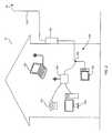
- FIG. 2is a graphical representation of a premise of a user arranged in accordance with an embodiment of the present invention
- FIG. 3is a circuit diagram of an upstream bandwidth conditioning device made in accordance with an embodiment of the present invention.
- FIG. 4is a circuit diagram of an upstream bandwidth conditioning device made in accordance with an embodiment of the present invention.
- FIG. 5is a circuit diagram of an upstream bandwidth conditioning device made in accordance with an embodiment of the present invention.
- a CATV systemtypically includes a supplier 20 that transmits a downstream bandwidth, such as RF signals, digital signals, and/or optical signals, to a user through a local distribution network 30 and receives an upstream bandwidth, such as RF signals, digital signals, and/or optical signals, from a user through the same local distribution network 30 .
- a tap 90is located at the local distribution network 30 to allow for the passage of the downstream/upstream bandwidth to/from the local distribution network 30 .
- a drop transmission line 120is then used to connect the tap 90 to a house 10 , 60 , an apartment building 50 , 70 , a coffee shop 80 , and so on.
- an upstream bandwidth conditioning device 100 of the present inventionmay be typically connected in series between the drop transmission line 120 and a user's premise distribution system 130 .
- the upstream bandwidth conditioning device 100can be placed at any location between the tap 90 and the user's premise distribution system 130 . This location can be conveniently located within a premise (e.g., the house 10 , the apartment building 50 , etc.), or proximate to the premise (e.g., the house 60 , the apartment building 70 , etc.). It should be understood that the upstream bandwidth conditioning device 100 can be placed at any location, such as the coffee shop 80 or other business, where CATV services, including internet services, VOIP services, or other unidirectional/bidirectional services may be used.
- CATV servicesincluding internet services, VOIP services, or other unidirectional/bidirectional services may be used.
- the user's premise distribution system 130may be split using a splitter 190 so that the downstream/upstream bandwidth can pass to/from a variety of devices, such as a modem 140 and a television 150 , in accordance with practices well known in the art.
- the modem 140may include VOIP functionality affording telephone 170 services and may include a router affording internet services for a laptop computer 180 and a desktop computer 160 , for example.
- STBset-top box
- STUset-top unit
- each upstream bandwidth conditioning device 100may be used with two or more devices (e.g., a modem, a STB, a STU, and/or a dedicated VOIP server) that transmit desirable upstream information signals via the upstream bandwidth.
- devicese.g., a modem, a STB, a STU, and/or a dedicated VOIP server
- Many usersmay not yet subscribe to any premium CATV services, such as the internet, VOIP, Pay-Per-View, etc., that require the use of a modem 140 , STB, and/or STU, which create the desirable upstream information signals to be sent in the upstream bandwidth. Nonetheless, significant amounts of undesirable interference signals can be eliminated from the upstream bandwidth in the local distribution network 30 by terminating the return path within the premise of a user that does not subscribe to any these premium services.
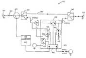
- an upstream bandwidth conditioning device 100made in accordance with one embodiment of the present invention includes a supplier side connector 310 and user side connector 320 .
- the supplier side connector 310 and the user side connector 320can each be a traditional threaded “F” type 75 ohm connector so that the upstream bandwidth conditioning device 100 can be easily placed in series with the drop transmission line 120 and the premise distribution system 130 , which already use “F” type connectors. This “in series” placement ensures that all of the all of the downstream/upstream signals pass through the upstream bandwidth conditioning device 100 .
- each of the supplier side connector 310 and the user side connector 320may be a a connector other than an “F” type connector.
- At least one of the connectors 340 , 350may be proprietary connector to hinder attempts at tampering with or unauthorized attempts to access the upstream bandwidth conditioning device 100 .
- Other connector typesmay also be used depending on the type and/or size of the drop transmission line 120 , the premise distribution system 130 , or system impedance other than 75 ohms. With regard to the latter, it should be understood that connectors are purposefully varied in some instances to avoid the placement of components having one characteristic impedance (e.g., 75 Ohms) in a system having another characteristic impedance (e.g., 50 Ohms).
- the upstream bandwidth conditioning device 100further includes a supplier side diplexer filter 330 and a user side diplexer filter 340 that create a forward path 360 for the downstream bandwidth and a return path 370 for the upstream bandwidth.
- a supplier side diplexer filter 330 and a user side diplexer filter 340that create a forward path 360 for the downstream bandwidth and a return path 370 for the upstream bandwidth.
- known devicessuch as signal amplifiers, signal attenuation devices, electrical protection devices, etc. can be included.
- the return path 370includes a signal amplifier 380 , which can be any of the well known devices for amplifying a signal, whether it is an electromagnetic signal or an optical signal.
- the signal amplifier 380is selectively connected in series with the return path 370 by an amplifier switch 390 , which is represented in an open state. In its open state, the amplifier switch 390 effectively splits the return path 370 into two parts, a supplier side portion 365 and a user side portion 375 . While it is not shown in FIG. 3 , the amplifying device 380 may be selectively connected to the supplier side portion 365 of the return path 370 in a manner similar to how the signal amplifier 380 is selectively connected to the user side portion 375 of the return path 370 by the amplifier switch 390 .
- the signal amplification devicereceives electrical energy via an amplifier energy switch 400 , which is represented in an open state. While there may be no injurious effects to providing constant power to the signal amplifier 380 , there may be a power savings by not powering the signal amplifier 380 when it is not in use.
- switchesi.e. amplifier switch 390 and amplifier energy switch 400
- the switches 390 and 400are typical switches for their intended purposes.
- the switch controllermay be a CPU, an analog circuit, and/or a simple mechanical connection that actuates each of the switches between a first position and a second position based on an input from a CPU 460 and/or a physical switch 470 .
- the configuration shown in the embodiment of FIG. 3is a default position such that the amplifier switch 390 and the amplifier energy switch 400 are in their first position (i.e. an open position). In this first position (i.e. the default position), signals do not pass through the signal amplifier 380 and the signal amplifier 380 is not being powered.
- the configuration shown in FIG. 3is currently intended to be a default configuration for the upstream bandwidth conditioning device 100 , because it is believed that such devices would be used in or on the premise of users, who do not subscribe to any service that utilizes the upstream bandwidth. More simply, the present embodiment shown in FIG. 3 defaults to a position with the return path is open and the signal amplifier 380 deactivated. Accordingly, when the physical switch 470 is closed, the switch controller 450 actuates the switches 390 , and 400 from their first position (i.e. default position), as shown, to their second positions, which connect and energize the signal amplifier 380 . The same action can be initiated by the CPU 460 in the manner discussed below. It should be understood that the embodiment shown in FIG. 3 can be configured such that the second position of the switches 390 , 400 is the default position.
- the CPU 460determines whether to instruct the switch controller 450 to activate the switches 390 , 400 based on an information transmission signal sent by the supplier 20 .
- a signal coupler 470allows for a pilot receiver 480 to receive the information transmission signal, such as a tone, a coded operational signal, or other well known information transmission signal that can be understood by the CPU 460 to indicate a desired switch position.
- the information signalis sampled by the signal coupler 470 , and the sampled signal is filtered and sent to the pilot receiver 480 to demodulate and extract the information that will be used by the CPU 460 .
- the frequency of the receiver 480may be set by the CPU 460 and can be tuned by a phase-locked loop control system (not specifically represented) in a manner that is well known in the art. It should be noted that the CPU 460 can be any one of a variety of devices, such as an analog logic circuit or a microprocessor.
- the frequency of the receiver 480can be set by the CPU 460 and can be tuned in any of the manners that are well known in the art.
- the receiver 480may also be fixed to a single frequency if and/or when that frequency is sufficient to carry the desired information transmission signal.
- the particular frequencyis only important to the degree that the receiver 480 must be tuned to a particular frequency where the information transmission signal is expected in order to receive the information transmission signal.
- the particular frequencyis a frequency within a range of 110-135 MHz because the components of the receiver 480 , a low power mixer FM IF system SA605DK and clock generator ADF4001, are relatively inexpensive for this frequency range.
- the particular frequenciesmay, as in the present case, be a frequency within a typical CATV channel, but between the video carrier frequency and audio carrier frequency.
- the information transmission signalcan be a tone, such as a 100 kHz tone that is RF modulated onto the particular frequency.
- the receiver 480may then include a tone demodulator, which are well known in the art, to identify whether a tone is present and provide an output to the CPU 460 indicating whether a tone is present. More detailed control, possibly to control the amount of amplification by the signal amplifier 380 , may also be accomplished by incorporating an information transmission signal that includes a coded operational signal.
- a coded operational signalmay be provided on the particular frequency along with the tone, or the coded operational signal may be provided by itself on the particular frequency.
- a coded operational signalis RF modulated along with the tone.
- the coded operational signalis provided at 500 MHz on the particular frequency, and provides for a transfer rate of 2400 baud.
- the mixer in the receiver 480provides two outputs, one with a band pass filter to pass the 100 Hz tone to the tone demodulator, and one with a band pass filter to pass the 500 MHz signals to a demodulator, which is well known in the art, to convert the RF signals into a data steam, such as RS232, suitable for use by the CPU 460 .
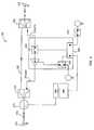
- an upstream bandwidth conditioning device 100made in accordance with another embodiment of the present invention includes all of the features discussed above in relation to FIG. 3 (similar reference numbers identifying similar features).
- the return path 370includes a supplier side termination device 410 selectively connected in series with the supplier side portion 365 between a ground and the low-pass filter portion of the supplier side diplexer set 330 by a supplier side termination switch 420 .
- the return path 370includes a user side termination device 430 selectively connected in series with the user side portion 375 between the ground and the low-pass filter portion of the user side diplexer set 340 by a user side termination switch 440 .
- switchesi.e. the supplier side termination switch 420 and user side termination switch 440 .
- the switches 420 and 440are typical switches for their intended purposes.
- Each of the amplifier switch 390 , the amplifier energy switch 400 , supplier side termination switch 420 , and the user side termination switch 440are controlled by the switch controller 450 .
- the switch controllermay be a CPU, an analog circuit, and/or a simple mechanical connection that actuates each of the switches between a first position and a second position based on an input from a CPU 460 and/or a physical switch 470 .
- the configuration shown in the embodiment of FIG. 4is a default position for the present embodiment such that the amplifier switch 390 and the amplifier energy switch 400 are in their first position (i.e. an open position), and the supplier side termination switch 420 and the user side termination switch 440 are in their first position (i.e. a closed position).
- first positioni.e. the default position
- signalsdo not pass through the signal amplifier 380 and the signal amplifier 380 is not being powered.
- the supplier side portion 365 of the return path 370is terminated through the supplier side termination device 410 and the user side portion 375 of the return path 370 is terminated through the user side termination device 430 .
- the configuration shown in FIG. 4is currently intended to be a default configuration for the upstream bandwidth conditioning device 100 , because it is believed that such devices would be used in or on the premise of users, who do not subscribe to any service that utilizes the upstream bandwidth. More simply, the present embodiment shown in FIG. 4 defaults to a position with the return path terminated and the signal amplifier 380 deactivated. Accordingly, when the physical switch 470 is closed, the switch controller 450 actuates the switches 390 , 400 , 420 , and 430 from their first position (i.e. default position), as shown, to their second positions, which connect and energize the signal amplifier 380 and disconnect the termination devices 410 , 430 .
- the CPU 460determines whether to instruct the switch controller 450 to activate the switches 390 , 400 , 420 , 440 based on an information transmission signal sent by the supplier 20 .
- FIG. 3Other embodiments are envisaged that provide a feature level that is in between the embodiment shown in FIG. 3 and the embodiment shown in FIG. 4 .
- an embodimentis envisaged that includes the supplier side termination device 410 and the respective supplier side termination switch 420 , but does not include the user side termination device 430 and the respective user side termination switch 440 .
- Such an embodimentmay be useful if there is a need to prevent reflections of other upstream bandwidth signals produced by other users.
- another embodimentis envisaged that includes the user side termination device 430 and the respective user side termination switch 440 , but does not include the supplier side termination device 410 and the respective supplier side termination switch.
- Such an embodimentmay be useful if there is a need to prevent reflections of any undesirable interference signals from affecting the downstream bandwidth in the premise.
- the amplifier switch 390may be removed if the amplifier 380 is such that it effectively separates the forward path 370 into the supplier side portion 365 and the user side portion 375 .
- the amplifier switch 390may be eliminated.
- an upstream bandwidth conditioning device 100may be provided in the premise distribution system.
- an upstream bandwidth conditioning device 100may be located on any leg of the premise distribution system 130 after the splitter 190 . While only two legs are shown, the leg between the splitter 190 and the modem 140 and the leg between the splitter 190 and the television 150 , it should be understood that there may be many legs.
- each of the upstream bandwidth conditioning devices 100may be separately identifiable and/or controllable such that any one of the upstream bandwidth conditioning devices 100 may be indentified and/or controlled separately from the remaining upstream bandwidth conditioning devices 100 .
- the splitter 190may be replaced with a splitter 290 , which includes one or more of the upstream bandwidth conditioning devices 100 that may replace the upstream bandwidth conditioning device 100 represented in FIG. 2 .
- the splitter 290may be replaced with a splitter 290 , which includes one or more of the upstream bandwidth conditioning devices 100 that may replace the upstream bandwidth conditioning device 100 represented in FIG. 2 .
- there may be one upstream bandwidth conditioning device 100 for a single user side connector 320 of the splitter 290and/or there may be one upstream bandwidth conditioning device associated with two or more user side connectors 320 .
- each of the upstream bandwidth conditioning devices 100 in the splitter 290may be identified and/or controlled separately from one another either by an informational signal from the supplier 20 and/or by a user/technician on site. If such a splitter 290 is implemented, the upstream bandwidth conditioning device 100 represented may not be present, but could remain for the purpose of terminating the return path for the entire premise.
Landscapes
- Engineering & Computer Science (AREA)
- Multimedia (AREA)
- Signal Processing (AREA)
- Computer Networks & Wireless Communication (AREA)
- Databases & Information Systems (AREA)
- Two-Way Televisions, Distribution Of Moving Picture Or The Like (AREA)
- Cable Transmission Systems, Equalization Of Radio And Reduction Of Echo (AREA)
Abstract
Description
Claims (50)
Priority Applications (3)
| Application Number | Priority Date | Filing Date | Title |
|---|---|---|---|
| US12/534,971US8990881B2 (en) | 2009-03-30 | 2009-08-04 | Upstream bandwidth conditioning device |
| PCT/US2010/024281WO2010117496A2 (en) | 2009-03-30 | 2010-02-16 | Upstream bandwidth conditioning device |
| US14/665,655US20150201239A1 (en) | 2009-03-30 | 2015-03-23 | Upstream bandwidth conditioning device |
Applications Claiming Priority (3)
| Application Number | Priority Date | Filing Date | Title |
|---|---|---|---|
| US16480409P | 2009-03-30 | 2009-03-30 | |
| US18669109P | 2009-06-12 | 2009-06-12 | |
| US12/534,971US8990881B2 (en) | 2009-03-30 | 2009-08-04 | Upstream bandwidth conditioning device |
Related Child Applications (1)
| Application Number | Title | Priority Date | Filing Date |
|---|---|---|---|
| US14/665,655ContinuationUS20150201239A1 (en) | 2009-03-30 | 2015-03-23 | Upstream bandwidth conditioning device |
Publications (2)
| Publication Number | Publication Date |
|---|---|
| US20100251323A1 US20100251323A1 (en) | 2010-09-30 |
| US8990881B2true US8990881B2 (en) | 2015-03-24 |
Family
ID=42785982
Family Applications (2)
| Application Number | Title | Priority Date | Filing Date |
|---|---|---|---|
| US12/534,971Expired - Fee RelatedUS8990881B2 (en) | 2009-03-30 | 2009-08-04 | Upstream bandwidth conditioning device |
| US14/665,655AbandonedUS20150201239A1 (en) | 2009-03-30 | 2015-03-23 | Upstream bandwidth conditioning device |
Family Applications After (1)
| Application Number | Title | Priority Date | Filing Date |
|---|---|---|---|
| US14/665,655AbandonedUS20150201239A1 (en) | 2009-03-30 | 2015-03-23 | Upstream bandwidth conditioning device |
Country Status (2)
| Country | Link |
|---|---|
| US (2) | US8990881B2 (en) |
| WO (1) | WO2010117496A2 (en) |
Families Citing this family (13)
| Publication number | Priority date | Publication date | Assignee | Title |
|---|---|---|---|---|
| EP2415260A1 (en)* | 2009-04-01 | 2012-02-08 | David Zilberberg | System for reducing noise in a catv home amplifier upstream path and a method thereof |
| US9264012B2 (en) | 2012-06-25 | 2016-02-16 | Ppc Broadband, Inc. | Radio frequency signal splitter |
| US9807467B2 (en) | 2014-01-21 | 2017-10-31 | Commscope, Inc. | Upstream noise suppression circuits and related radio frequency subscriber drop equipment and methods |
| CN105578279B (en)* | 2015-11-17 | 2019-03-12 | 深圳Tcl数字技术有限公司 | Television set alarm method and system |
| WO2017123717A1 (en) | 2016-01-12 | 2017-07-20 | Ppc Broadband, Inc. | Network interface device with dynamic noise conditioning |
| CA3012728A1 (en)* | 2016-01-29 | 2017-08-03 | Ppc Broadband, Inc. | Dynamic noise mitigation device |
| EP3457636B1 (en)* | 2016-05-11 | 2021-12-22 | KT Corporation | Network management device, customer premises equipment registration method therefor, and method for providing internet service to customer premises equipment |
| US10425617B2 (en) | 2016-10-03 | 2019-09-24 | Enseo, Inc. | Distribution element for a self-calibrating RF network and system and method for use of the same |
| US10701569B2 (en) | 2016-10-03 | 2020-06-30 | Enseo, Inc. | Self-calibrating RF network and system and method for use of the same |
| US10798374B2 (en) | 2016-10-28 | 2020-10-06 | Enseo, Inc. | Set-top box with self-monitoring and system and method for use of same |
| US11831934B2 (en) | 2022-01-11 | 2023-11-28 | Enseo, Llc | Set-top box with self-monitoring and system and method for use of same |
| US12212792B2 (en) | 2016-10-28 | 2025-01-28 | Enseo, Llc | Set-top box with self-monitoring and system and method for use of same |
| WO2019022962A1 (en) | 2017-07-27 | 2019-01-31 | Ppc Broadband, Inc. | Network interface devices with upstream noise suppressors |
Citations (107)
| Publication number | Priority date | Publication date | Assignee | Title |
|---|---|---|---|---|
| US3790909A (en) | 1973-01-26 | 1974-02-05 | Gte Sylvania Inc | Varactor tuner band switch circuitry |
| US3924187A (en) | 1974-05-14 | 1975-12-02 | Magnavox Co | Two-way cable television system with enhanced signal-to-noise ratio for upstream signals |
| JPS5580989A (en) | 1978-12-15 | 1980-06-18 | Nec Corp | Automatic balancing system for exchange |
| JPS55132126A (en) | 1979-03-31 | 1980-10-14 | Fujitsu Ltd | Selective switching circuit of signal transmission line |
| JPS5791055A (en) | 1980-11-27 | 1982-06-07 | Toshiba Corp | Branching device |
| JPS58101582A (en) | 1981-12-12 | 1983-06-16 | Murata Mfg Co Ltd | Catv system |
| US4512033A (en) | 1982-11-29 | 1985-04-16 | C-Cor Labs, Inc. | Remote level adjustment system for use in a multi-terminal communications system |
| US4520508A (en) | 1982-12-21 | 1985-05-28 | General Instrument Corporation | Subscriber terminal for monitoring radio-frequency signal ingress into cable television systems |
| JPS61157035A (en) | 1984-12-28 | 1986-07-16 | Fujitsu Ltd | Impedance matching system |
| US4648123A (en) | 1982-11-29 | 1987-03-03 | C-Cor Labs, Inc. | Remote level measurement system for use in a multi-terminal communications system |
| US4677390A (en) | 1985-05-31 | 1987-06-30 | Texscan Corporation | Low-power feedforward amplifier |
| US4961218A (en) | 1989-05-17 | 1990-10-02 | Tollgrade Communications, Inc. | Enhanced line powered amplifier |
| US4982440A (en) | 1988-04-21 | 1991-01-01 | Videotron Ltee | CATV network with addressable filters receiving MSK upstream signals |
| US5010399A (en) | 1989-07-14 | 1991-04-23 | Inline Connection Corporation | Video transmission and control system utilizing internal telephone lines |
| US5014309A (en) | 1988-03-10 | 1991-05-07 | Scientific-Atlanta, Inc. | Off-premises cable television channel interdiction method and apparatus |
| US5126840A (en) | 1988-04-21 | 1992-06-30 | Videotron Ltee | Filter circuit receiving upstream signals for use in a CATV network |
| US5214505A (en) | 1991-04-08 | 1993-05-25 | Hughes Aircraft Company | Automatic rf equalization in passenger aircraft video distribution system |
| US5231660A (en) | 1988-03-10 | 1993-07-27 | Scientific-Atlanta, Inc. | Compensation control for off-premises CATV system |
| JPH05191416A (en) | 1992-01-10 | 1993-07-30 | Matsushita Electric Ind Co Ltd | Automatic termination resistor connector |
| US5369642A (en) | 1992-05-29 | 1994-11-29 | Nec Corporation | Switcher for redundant signal transmission system |
| JPH0738580A (en) | 1993-06-28 | 1995-02-07 | Nec Corp | Variable terminating system |
| US5548255A (en) | 1995-06-23 | 1996-08-20 | Microphase Corporation | Compact diplexer connection circuit |
| US5745836A (en) | 1995-09-01 | 1998-04-28 | Cable Television Laboratories, Inc. | Undesirable energy suppression system in a contention based communication network |
| US5768682A (en) | 1996-07-26 | 1998-06-16 | At&T Corp | Shared hybrid-fiber coax transmission system having improved bandwidth in the stream channel with ingress noise reduction |
| US5815794A (en) | 1995-09-01 | 1998-09-29 | Cable Television Laboratories, Inc. | Undesirable energy suppression system in the return path of a bidirectional cable network having dynamically allocated time slots |
| US5839052A (en) | 1996-02-08 | 1998-11-17 | Qualcom Incorporated | Method and apparatus for integration of a wireless communication system with a cable television system |
| US5881362A (en) | 1994-11-30 | 1999-03-09 | General Instrument Corporation Of Delaware | Method of ingress noise reduction in calbe return paths |
| JPH1169334A (en) | 1997-08-19 | 1999-03-09 | Miharu Tsushin Kk | Standby tv modulator for catv head end |
| US5893024A (en)* | 1996-08-13 | 1999-04-06 | Motorola, Inc. | Data communication apparatus and method thereof |
| US5937330A (en) | 1997-02-18 | 1999-08-10 | General Instrument Corporation | Settop terminal controlled return path filter for minimizing noise ingress on bidirectional cable systems |
| US5950111A (en) | 1997-09-25 | 1999-09-07 | Lucent Technologies Inc. | Self-terminating coaxial to unshielded twisted-pair cable passive CATV distribution panel |
| US5970053A (en) | 1996-12-24 | 1999-10-19 | Rdl, Inc. | Method and apparatus for controlling peak factor of coherent frequency-division-multiplexed systems |
| US5990929A (en) | 1998-08-14 | 1999-11-23 | Sandaluk; Anthony J. | Return amplifier for two way cable transmission and method |
| US6014547A (en) | 1997-04-28 | 2000-01-11 | General Instrument Corporation | System for enhancing the performance of a CATV settop terminal |
| US6049693A (en) | 1996-08-15 | 2000-04-11 | Com21, Inc. | Upstream ingress noise blocking filter for cable television system |
| WO2000024124A1 (en) | 1998-10-22 | 2000-04-27 | Ericsson, Inc. | Dual-band, dual-mode power amplifier with reduced power loss |
| US6069960A (en) | 1996-09-05 | 2000-05-30 | Sony Corporation | Connector device for information-handling apparatus and connector device for stereophonic audio/video apparatus |
| USH1858H (en)* | 1998-06-26 | 2000-09-05 | Scientific-Atlanta, Inc. | Radio frequency sensed, switched reverse path tap |
| JP2001016557A (en) | 1999-06-29 | 2001-01-19 | Fujitsu Ltd | Two-way CATV system |
| US6199207B1 (en) | 1996-06-03 | 2001-03-06 | Scientific-Atlanta, Inc. | Method and apparatus for routing signals through a cable television signal distribution amplifier |
| US6205138B1 (en) | 1998-04-24 | 2001-03-20 | International Business Machines Corporation | Broadband any point to any point switch matrix |
| JP2001177580A (en) | 1999-12-20 | 2001-06-29 | Sony Corp | Impedance adapting system |
| US20010016950A1 (en) | 2000-02-14 | 2001-08-23 | Syuuji Matsuura | Cable modem tuner |
| WO2001072005A1 (en) | 2000-03-17 | 2001-09-27 | Transcorp Systems Pty Ltd | Digital data splitter with switch and automatic termination restoration |
| JP2001326916A (en) | 2000-05-17 | 2001-11-22 | Secom Co Ltd | Ingress noise monitoring system and device |
| US6348837B1 (en) | 2000-08-08 | 2002-02-19 | Scientific-Atlanta, Inc. | Bi-directional amplifier having a single gain block for amplifying both forward and reverse signals |
| US6348955B1 (en) | 1998-02-23 | 2002-02-19 | Zenith Electronics Corporation | Tuner with switched analog and digital demodulators |
| US6373349B2 (en) | 2000-03-17 | 2002-04-16 | Bae Systems Information And Electronic Systems Integration Inc. | Reconfigurable diplexer for communications applications |
| US6377316B1 (en) | 1998-02-23 | 2002-04-23 | Zenith Electronics Corporation | Tuner with switched analog and digital modulators |
| WO2002033969A1 (en) | 2000-10-16 | 2002-04-25 | Xtend Networks Ltd. | System and method for expanding the operational bandwidth of a communication system |
| US6388539B1 (en) | 2001-04-16 | 2002-05-14 | At&T Corp. | Broadband switch/coupler |
| US6425132B1 (en) | 1998-04-06 | 2002-07-23 | Wavetek Corporation | Ingress testing of CATV system utilizing remote selection of CATV node |
| US20020141347A1 (en) | 2001-03-30 | 2002-10-03 | Harp Jeffrey C. | System and method of reducing ingress noise |
| US20020144292A1 (en) | 2001-02-19 | 2002-10-03 | Jun Uemura | Bi-directional CATV system, line equipment, center equipment |
| US20020166124A1 (en) | 2001-05-04 | 2002-11-07 | Itzhak Gurantz | Network interface device and broadband local area network using coaxial cable |
| WO2002091676A1 (en) | 2001-05-08 | 2002-11-14 | Hoseo Telecom Co., Ltd | Subscriber tap-off capable of monitoring state of transmission line at subscriber end, and remote control system and method using the same |
| US6495998B1 (en) | 2000-09-28 | 2002-12-17 | Sunrise Telecom Corp. | Selectable band-pass filtering apparatus and method |
| US6498925B1 (en) | 1999-05-13 | 2002-12-24 | Denso Corporation | Transmit power control circuit |
| US6510152B1 (en) | 1997-12-31 | 2003-01-21 | At&T Corp. | Coaxial cable/twisted pair fed, integrated residence gateway controlled, set-top box |
| US6560778B1 (en) | 1999-03-29 | 2003-05-06 | Masprodenkoh Kabushikikaisha | Tap device of cable broadcasting system |
| US6570928B1 (en) | 1999-01-05 | 2003-05-27 | Masprodenkoh Kabushikikaisha | Cable broadcasting system |
| US6587012B1 (en) | 1999-10-01 | 2003-07-01 | Arris International, Inc. | Automatic slope and gain (ASG) detector technique including a pilot signal |
| US6600900B1 (en) | 2000-05-09 | 2003-07-29 | John Mezzalingua Associates, Inc. | System and method providing bi-directional communication services between a service provider and a plurality of subscribers |
| US6622304B1 (en) | 1996-09-09 | 2003-09-16 | Thomas W. Carhart | Interface system for computing apparatus and communications stations |
| US6640338B1 (en) | 1999-01-27 | 2003-10-28 | Masprodenkoh Kabushikikaisha | Electronic device for cable broadcasting system |
| US6678893B1 (en) | 1997-12-26 | 2004-01-13 | Samsung Electronics Co., Ltd. | Bidirectional trunk amplifier and cable modem for cable hybrid fiber and coax network which utilizes an upstream pilot signal |
| US6683513B2 (en) | 2000-10-26 | 2004-01-27 | Paratek Microwave, Inc. | Electronically tunable RF diplexers tuned by tunable capacitors |
| JP2004080483A (en) | 2002-08-20 | 2004-03-11 | Ntt Communications Kk | Adapter for VoIP |
| US6725462B1 (en) | 2000-04-19 | 2004-04-20 | At&T Corp. | Optimizing upstream transmission in a cable television distribution plant |
| US6728968B1 (en) | 1999-06-17 | 2004-04-27 | Fujitsu Limited | Upward-joining-noise decreasing method and apparatus |
| US6757910B1 (en) | 2000-06-08 | 2004-06-29 | C-Cor.Net Corporation | Adaptive filter for reducing ingress noise in CATV return signals |
| US20040172659A1 (en) | 2001-07-13 | 2004-09-02 | Ljungdahl Kjell Arne | Arrangement for reduction of noise transmitted from a local cable tv network |
| US6804828B1 (en) | 1998-12-03 | 2004-10-12 | Masprodenkoh Kabushikikaisha | Tap device of cable broadcasting system |
| US20040229561A1 (en) | 2003-02-28 | 2004-11-18 | Cowley Nicholas Paul | Tuner |
| JP2005005875A (en) | 2003-06-10 | 2005-01-06 | Nec Tohoku Ltd | VoIP SWITCHING DEVICE |
| US6845232B2 (en) | 2002-03-25 | 2005-01-18 | Broadcom Corporation | Analog peak detection circuitry for radio receivers |
| US20050034168A1 (en) | 1993-05-28 | 2005-02-10 | Mediaone Group, Inc. | Method and apparatus for delivering secured telephony service in a hybrid coaxial cable network |
| US6868552B1 (en) | 1999-06-07 | 2005-03-15 | Fujitsu Limited | Ingress noise control system and ingress noise blocking device |
| US6877166B1 (en) | 2000-01-18 | 2005-04-05 | Cisco Technology, Inc. | Intelligent power level adjustment for cable modems in presence of noise |
| US6888883B1 (en)* | 1999-06-25 | 2005-05-03 | Cisco Technology, Inc. | Method and apparatus for reducing noise leakage from a cable modem |
| US6928175B1 (en) | 2000-06-14 | 2005-08-09 | Creative Technology Ltd. | Audio system with optional auto-switching secondary connector, and method for same |
| US20050183130A1 (en) | 2004-02-12 | 2005-08-18 | Sadja Aran L. | Cable diagnostic and monitoring system |
| US20050283815A1 (en) | 2004-06-01 | 2005-12-22 | Brooks Paul D | Apparatus and methods for network interface and spectrum management |
| US20050289632A1 (en) | 2004-06-01 | 2005-12-29 | Brooks Paul D | Controlled isolation splitter apparatus and methods |
| US20060015921A1 (en) | 2004-07-19 | 2006-01-19 | Jay Vaughan | VoIP drop amplifier |
| US7003275B1 (en) | 2000-05-18 | 2006-02-21 | Broadband Innovations, Inc. | Agile frequency converter for multichannel systems using IF-RF level exhange and tunable filters |
| US7029293B2 (en) | 2004-08-20 | 2006-04-18 | Extreme Broadband Engineering, Llc | Ground block connector |
| US7039432B2 (en) | 2001-12-04 | 2006-05-02 | General Instrument Corporation | Dynamic upstream attenuation for ingress noise reduction |
| US20060205442A1 (en) | 2005-03-10 | 2006-09-14 | Neil Phillips | Bi-directional amplifier with non-interruptible port |
| US20060271986A1 (en)* | 2005-05-23 | 2006-11-30 | Mark Vogel | Methods, gating devices, and computer program products for determining a noise source in a communication network |
| US20060282871A1 (en) | 2005-06-13 | 2006-12-14 | Yao-Tsan Yo | Distribution method for noise control |
| US7162731B2 (en) | 2002-02-07 | 2007-01-09 | Advent Networks, Inc. | Radio frequency characterization of cable plant and corresponding calibration of communication equipment communicating via the cable plant |
| JP2007166110A (en) | 2005-12-12 | 2007-06-28 | Matsushita Electric Works Ltd | Transmission system and branch device thereof |
| JP2007166109A (en) | 2005-12-12 | 2007-06-28 | Matsushita Electric Works Ltd | Branch device of transmission system, and transmission system |
| US7283479B2 (en) | 2000-02-16 | 2007-10-16 | Spacenet Proxilliant Systems Ab | Cable TV system or other similar communication system |
| US20070288981A1 (en) | 2006-06-13 | 2007-12-13 | Hwa Lin Electronic (Shenzhen)Co., Ltd. | CATV system and automatic noise controller |
| US20070288982A1 (en) | 2006-06-13 | 2007-12-13 | Comcast Cable Holdings, Llc | Dynamic ingress arrester |
| US20080022344A1 (en) | 2006-07-07 | 2008-01-24 | Scientific-Atlanta, Inc. | Format Converter with Smart Multitap with Digital Forward and Reverse |
| US20080040764A1 (en) | 2001-07-20 | 2008-02-14 | Hillel Weinstein | System, apparatus and method for expanding the operational bandwidth of a communication system |
| US20080127287A1 (en) | 2006-11-28 | 2008-05-29 | John Mezzalingua Associates, Inc. | Apparatus and method for embedding/detecting an auxiliary signal within a catv traffic stream |
| US7454252B2 (en) | 2006-03-08 | 2008-11-18 | Moore Industries International, Inc. | Redundant fieldbus system |
| US20090031391A1 (en) | 2007-03-08 | 2009-01-29 | Emerson Network Power Connectivity Solutions | Electronically controlled catv system |
| US20090047917A1 (en) | 2005-03-10 | 2009-02-19 | Phillips Neil P | Signal Amplifiers Having Non-Interruptible Communication Paths |
| US7505819B2 (en) | 2006-02-08 | 2009-03-17 | Moore Industries International, Inc. | Redundant fieldbus system |
| US20090077608A1 (en) | 2007-09-14 | 2009-03-19 | Romerein Robert L | Constant input port impedance for CATV amplifier with passive modem port |
| US7555309B2 (en)* | 2005-04-15 | 2009-06-30 | Evertz Microsystems Ltd. | Radio frequency router |
| US20100095344A1 (en)* | 2008-10-13 | 2010-04-15 | Newby Charles F | Ingress Noise Inhibiting Network Interface Device and Method for Cable Television Networks |
Family Cites Families (3)
| Publication number | Priority date | Publication date | Assignee | Title |
|---|---|---|---|---|
| US1858A (en)* | 1840-11-26 | Cooking-stove | ||
| JP4740464B2 (en)* | 2000-04-27 | 2011-08-03 | マスプロ電工株式会社 | Bi-directional CATV system, transmission line equipment, center equipment |
| AUPR399301A0 (en)* | 2001-03-27 | 2001-04-26 | Silverbrook Research Pty. Ltd. | An apparatus and method(ART106) |
- 2009
- 2009-08-04USUS12/534,971patent/US8990881B2/ennot_activeExpired - Fee Related
- 2010
- 2010-02-16WOPCT/US2010/024281patent/WO2010117496A2/enactiveApplication Filing
- 2015
- 2015-03-23USUS14/665,655patent/US20150201239A1/ennot_activeAbandoned
Patent Citations (109)
| Publication number | Priority date | Publication date | Assignee | Title |
|---|---|---|---|---|
| US3790909A (en) | 1973-01-26 | 1974-02-05 | Gte Sylvania Inc | Varactor tuner band switch circuitry |
| US3924187A (en) | 1974-05-14 | 1975-12-02 | Magnavox Co | Two-way cable television system with enhanced signal-to-noise ratio for upstream signals |
| JPS5580989A (en) | 1978-12-15 | 1980-06-18 | Nec Corp | Automatic balancing system for exchange |
| JPS55132126A (en) | 1979-03-31 | 1980-10-14 | Fujitsu Ltd | Selective switching circuit of signal transmission line |
| JPS5791055A (en) | 1980-11-27 | 1982-06-07 | Toshiba Corp | Branching device |
| JPS58101582A (en) | 1981-12-12 | 1983-06-16 | Murata Mfg Co Ltd | Catv system |
| US4648123A (en) | 1982-11-29 | 1987-03-03 | C-Cor Labs, Inc. | Remote level measurement system for use in a multi-terminal communications system |
| US4512033A (en) | 1982-11-29 | 1985-04-16 | C-Cor Labs, Inc. | Remote level adjustment system for use in a multi-terminal communications system |
| US4520508A (en) | 1982-12-21 | 1985-05-28 | General Instrument Corporation | Subscriber terminal for monitoring radio-frequency signal ingress into cable television systems |
| JPS61157035A (en) | 1984-12-28 | 1986-07-16 | Fujitsu Ltd | Impedance matching system |
| US4677390A (en) | 1985-05-31 | 1987-06-30 | Texscan Corporation | Low-power feedforward amplifier |
| US5014309A (en) | 1988-03-10 | 1991-05-07 | Scientific-Atlanta, Inc. | Off-premises cable television channel interdiction method and apparatus |
| US5231660A (en) | 1988-03-10 | 1993-07-27 | Scientific-Atlanta, Inc. | Compensation control for off-premises CATV system |
| US4982440A (en) | 1988-04-21 | 1991-01-01 | Videotron Ltee | CATV network with addressable filters receiving MSK upstream signals |
| US5126840A (en) | 1988-04-21 | 1992-06-30 | Videotron Ltee | Filter circuit receiving upstream signals for use in a CATV network |
| US4961218A (en) | 1989-05-17 | 1990-10-02 | Tollgrade Communications, Inc. | Enhanced line powered amplifier |
| US5010399A (en) | 1989-07-14 | 1991-04-23 | Inline Connection Corporation | Video transmission and control system utilizing internal telephone lines |
| US5214505A (en) | 1991-04-08 | 1993-05-25 | Hughes Aircraft Company | Automatic rf equalization in passenger aircraft video distribution system |
| JPH05191416A (en) | 1992-01-10 | 1993-07-30 | Matsushita Electric Ind Co Ltd | Automatic termination resistor connector |
| US5369642A (en) | 1992-05-29 | 1994-11-29 | Nec Corporation | Switcher for redundant signal transmission system |
| US20050034168A1 (en) | 1993-05-28 | 2005-02-10 | Mediaone Group, Inc. | Method and apparatus for delivering secured telephony service in a hybrid coaxial cable network |
| JPH0738580A (en) | 1993-06-28 | 1995-02-07 | Nec Corp | Variable terminating system |
| US5881362A (en) | 1994-11-30 | 1999-03-09 | General Instrument Corporation Of Delaware | Method of ingress noise reduction in calbe return paths |
| US5548255A (en) | 1995-06-23 | 1996-08-20 | Microphase Corporation | Compact diplexer connection circuit |
| US5745836A (en) | 1995-09-01 | 1998-04-28 | Cable Television Laboratories, Inc. | Undesirable energy suppression system in a contention based communication network |
| US5815794A (en) | 1995-09-01 | 1998-09-29 | Cable Television Laboratories, Inc. | Undesirable energy suppression system in the return path of a bidirectional cable network having dynamically allocated time slots |
| US5839052A (en) | 1996-02-08 | 1998-11-17 | Qualcom Incorporated | Method and apparatus for integration of a wireless communication system with a cable television system |
| US6199207B1 (en) | 1996-06-03 | 2001-03-06 | Scientific-Atlanta, Inc. | Method and apparatus for routing signals through a cable television signal distribution amplifier |
| US5768682A (en) | 1996-07-26 | 1998-06-16 | At&T Corp | Shared hybrid-fiber coax transmission system having improved bandwidth in the stream channel with ingress noise reduction |
| US5893024A (en)* | 1996-08-13 | 1999-04-06 | Motorola, Inc. | Data communication apparatus and method thereof |
| US6094211A (en) | 1996-08-15 | 2000-07-25 | Com21, Inc. | TV and data cable system ingress noise blocker |
| US6049693A (en) | 1996-08-15 | 2000-04-11 | Com21, Inc. | Upstream ingress noise blocking filter for cable television system |
| US6069960A (en) | 1996-09-05 | 2000-05-30 | Sony Corporation | Connector device for information-handling apparatus and connector device for stereophonic audio/video apparatus |
| US6622304B1 (en) | 1996-09-09 | 2003-09-16 | Thomas W. Carhart | Interface system for computing apparatus and communications stations |
| US5970053A (en) | 1996-12-24 | 1999-10-19 | Rdl, Inc. | Method and apparatus for controlling peak factor of coherent frequency-division-multiplexed systems |
| US5937330A (en) | 1997-02-18 | 1999-08-10 | General Instrument Corporation | Settop terminal controlled return path filter for minimizing noise ingress on bidirectional cable systems |
| US6014547A (en) | 1997-04-28 | 2000-01-11 | General Instrument Corporation | System for enhancing the performance of a CATV settop terminal |
| JPH1169334A (en) | 1997-08-19 | 1999-03-09 | Miharu Tsushin Kk | Standby tv modulator for catv head end |
| US5950111A (en) | 1997-09-25 | 1999-09-07 | Lucent Technologies Inc. | Self-terminating coaxial to unshielded twisted-pair cable passive CATV distribution panel |
| US6678893B1 (en) | 1997-12-26 | 2004-01-13 | Samsung Electronics Co., Ltd. | Bidirectional trunk amplifier and cable modem for cable hybrid fiber and coax network which utilizes an upstream pilot signal |
| US6510152B1 (en) | 1997-12-31 | 2003-01-21 | At&T Corp. | Coaxial cable/twisted pair fed, integrated residence gateway controlled, set-top box |
| US6377316B1 (en) | 1998-02-23 | 2002-04-23 | Zenith Electronics Corporation | Tuner with switched analog and digital modulators |
| US6348955B1 (en) | 1998-02-23 | 2002-02-19 | Zenith Electronics Corporation | Tuner with switched analog and digital demodulators |
| US6425132B1 (en) | 1998-04-06 | 2002-07-23 | Wavetek Corporation | Ingress testing of CATV system utilizing remote selection of CATV node |
| US6205138B1 (en) | 1998-04-24 | 2001-03-20 | International Business Machines Corporation | Broadband any point to any point switch matrix |
| USH1858H (en)* | 1998-06-26 | 2000-09-05 | Scientific-Atlanta, Inc. | Radio frequency sensed, switched reverse path tap |
| US5990929A (en) | 1998-08-14 | 1999-11-23 | Sandaluk; Anthony J. | Return amplifier for two way cable transmission and method |
| WO2000024124A1 (en) | 1998-10-22 | 2000-04-27 | Ericsson, Inc. | Dual-band, dual-mode power amplifier with reduced power loss |
| US6804828B1 (en) | 1998-12-03 | 2004-10-12 | Masprodenkoh Kabushikikaisha | Tap device of cable broadcasting system |
| US6570928B1 (en) | 1999-01-05 | 2003-05-27 | Masprodenkoh Kabushikikaisha | Cable broadcasting system |
| US6640338B1 (en) | 1999-01-27 | 2003-10-28 | Masprodenkoh Kabushikikaisha | Electronic device for cable broadcasting system |
| US6560778B1 (en) | 1999-03-29 | 2003-05-06 | Masprodenkoh Kabushikikaisha | Tap device of cable broadcasting system |
| US6498925B1 (en) | 1999-05-13 | 2002-12-24 | Denso Corporation | Transmit power control circuit |
| US6868552B1 (en) | 1999-06-07 | 2005-03-15 | Fujitsu Limited | Ingress noise control system and ingress noise blocking device |
| US6728968B1 (en) | 1999-06-17 | 2004-04-27 | Fujitsu Limited | Upward-joining-noise decreasing method and apparatus |
| US6888883B1 (en)* | 1999-06-25 | 2005-05-03 | Cisco Technology, Inc. | Method and apparatus for reducing noise leakage from a cable modem |
| JP2001016557A (en) | 1999-06-29 | 2001-01-19 | Fujitsu Ltd | Two-way CATV system |
| US6587012B1 (en) | 1999-10-01 | 2003-07-01 | Arris International, Inc. | Automatic slope and gain (ASG) detector technique including a pilot signal |
| JP2001177580A (en) | 1999-12-20 | 2001-06-29 | Sony Corp | Impedance adapting system |
| US6877166B1 (en) | 2000-01-18 | 2005-04-05 | Cisco Technology, Inc. | Intelligent power level adjustment for cable modems in presence of noise |
| US20010016950A1 (en) | 2000-02-14 | 2001-08-23 | Syuuji Matsuura | Cable modem tuner |
| US7283479B2 (en) | 2000-02-16 | 2007-10-16 | Spacenet Proxilliant Systems Ab | Cable TV system or other similar communication system |
| WO2001072005A1 (en) | 2000-03-17 | 2001-09-27 | Transcorp Systems Pty Ltd | Digital data splitter with switch and automatic termination restoration |
| US6373349B2 (en) | 2000-03-17 | 2002-04-16 | Bae Systems Information And Electronic Systems Integration Inc. | Reconfigurable diplexer for communications applications |
| US6725462B1 (en) | 2000-04-19 | 2004-04-20 | At&T Corp. | Optimizing upstream transmission in a cable television distribution plant |
| US6600900B1 (en) | 2000-05-09 | 2003-07-29 | John Mezzalingua Associates, Inc. | System and method providing bi-directional communication services between a service provider and a plurality of subscribers |
| JP2001326916A (en) | 2000-05-17 | 2001-11-22 | Secom Co Ltd | Ingress noise monitoring system and device |
| US7003275B1 (en) | 2000-05-18 | 2006-02-21 | Broadband Innovations, Inc. | Agile frequency converter for multichannel systems using IF-RF level exhange and tunable filters |
| US6757910B1 (en) | 2000-06-08 | 2004-06-29 | C-Cor.Net Corporation | Adaptive filter for reducing ingress noise in CATV return signals |
| US6928175B1 (en) | 2000-06-14 | 2005-08-09 | Creative Technology Ltd. | Audio system with optional auto-switching secondary connector, and method for same |
| US6348837B1 (en) | 2000-08-08 | 2002-02-19 | Scientific-Atlanta, Inc. | Bi-directional amplifier having a single gain block for amplifying both forward and reverse signals |
| US6495998B1 (en) | 2000-09-28 | 2002-12-17 | Sunrise Telecom Corp. | Selectable band-pass filtering apparatus and method |
| WO2002033969A1 (en) | 2000-10-16 | 2002-04-25 | Xtend Networks Ltd. | System and method for expanding the operational bandwidth of a communication system |
| US6683513B2 (en) | 2000-10-26 | 2004-01-27 | Paratek Microwave, Inc. | Electronically tunable RF diplexers tuned by tunable capacitors |
| US20020144292A1 (en) | 2001-02-19 | 2002-10-03 | Jun Uemura | Bi-directional CATV system, line equipment, center equipment |
| US20020141347A1 (en) | 2001-03-30 | 2002-10-03 | Harp Jeffrey C. | System and method of reducing ingress noise |
| US6388539B1 (en) | 2001-04-16 | 2002-05-14 | At&T Corp. | Broadband switch/coupler |
| US20020166124A1 (en) | 2001-05-04 | 2002-11-07 | Itzhak Gurantz | Network interface device and broadband local area network using coaxial cable |
| WO2002091676A1 (en) | 2001-05-08 | 2002-11-14 | Hoseo Telecom Co., Ltd | Subscriber tap-off capable of monitoring state of transmission line at subscriber end, and remote control system and method using the same |
| US20040172659A1 (en) | 2001-07-13 | 2004-09-02 | Ljungdahl Kjell Arne | Arrangement for reduction of noise transmitted from a local cable tv network |
| US20080040764A1 (en) | 2001-07-20 | 2008-02-14 | Hillel Weinstein | System, apparatus and method for expanding the operational bandwidth of a communication system |
| US7039432B2 (en) | 2001-12-04 | 2006-05-02 | General Instrument Corporation | Dynamic upstream attenuation for ingress noise reduction |
| US7162731B2 (en) | 2002-02-07 | 2007-01-09 | Advent Networks, Inc. | Radio frequency characterization of cable plant and corresponding calibration of communication equipment communicating via the cable plant |
| US6845232B2 (en) | 2002-03-25 | 2005-01-18 | Broadcom Corporation | Analog peak detection circuitry for radio receivers |
| JP2004080483A (en) | 2002-08-20 | 2004-03-11 | Ntt Communications Kk | Adapter for VoIP |
| US20040229561A1 (en) | 2003-02-28 | 2004-11-18 | Cowley Nicholas Paul | Tuner |
| JP2005005875A (en) | 2003-06-10 | 2005-01-06 | Nec Tohoku Ltd | VoIP SWITCHING DEVICE |
| US20050183130A1 (en) | 2004-02-12 | 2005-08-18 | Sadja Aran L. | Cable diagnostic and monitoring system |
| US20050289632A1 (en) | 2004-06-01 | 2005-12-29 | Brooks Paul D | Controlled isolation splitter apparatus and methods |
| US20050283815A1 (en) | 2004-06-01 | 2005-12-22 | Brooks Paul D | Apparatus and methods for network interface and spectrum management |
| US20060015921A1 (en) | 2004-07-19 | 2006-01-19 | Jay Vaughan | VoIP drop amplifier |
| US7530091B2 (en) | 2004-07-19 | 2009-05-05 | Pct International, Inc. | VOIP drop amplifier |
| US7029293B2 (en) | 2004-08-20 | 2006-04-18 | Extreme Broadband Engineering, Llc | Ground block connector |
| US20060205442A1 (en) | 2005-03-10 | 2006-09-14 | Neil Phillips | Bi-directional amplifier with non-interruptible port |
| US20090047917A1 (en) | 2005-03-10 | 2009-02-19 | Phillips Neil P | Signal Amplifiers Having Non-Interruptible Communication Paths |
| US7555309B2 (en)* | 2005-04-15 | 2009-06-30 | Evertz Microsystems Ltd. | Radio frequency router |
| US20060271986A1 (en)* | 2005-05-23 | 2006-11-30 | Mark Vogel | Methods, gating devices, and computer program products for determining a noise source in a communication network |
| US20060282871A1 (en) | 2005-06-13 | 2006-12-14 | Yao-Tsan Yo | Distribution method for noise control |
| JP2007166109A (en) | 2005-12-12 | 2007-06-28 | Matsushita Electric Works Ltd | Branch device of transmission system, and transmission system |
| JP2007166110A (en) | 2005-12-12 | 2007-06-28 | Matsushita Electric Works Ltd | Transmission system and branch device thereof |
| US7505819B2 (en) | 2006-02-08 | 2009-03-17 | Moore Industries International, Inc. | Redundant fieldbus system |
| US7454252B2 (en) | 2006-03-08 | 2008-11-18 | Moore Industries International, Inc. | Redundant fieldbus system |
| US20070288982A1 (en) | 2006-06-13 | 2007-12-13 | Comcast Cable Holdings, Llc | Dynamic ingress arrester |
| US20070288981A1 (en) | 2006-06-13 | 2007-12-13 | Hwa Lin Electronic (Shenzhen)Co., Ltd. | CATV system and automatic noise controller |
| US20080022344A1 (en) | 2006-07-07 | 2008-01-24 | Scientific-Atlanta, Inc. | Format Converter with Smart Multitap with Digital Forward and Reverse |
| US20080127287A1 (en) | 2006-11-28 | 2008-05-29 | John Mezzalingua Associates, Inc. | Apparatus and method for embedding/detecting an auxiliary signal within a catv traffic stream |
| US20090031391A1 (en) | 2007-03-08 | 2009-01-29 | Emerson Network Power Connectivity Solutions | Electronically controlled catv system |
| US20090077608A1 (en) | 2007-09-14 | 2009-03-19 | Romerein Robert L | Constant input port impedance for CATV amplifier with passive modem port |
| US20100095344A1 (en)* | 2008-10-13 | 2010-04-15 | Newby Charles F | Ingress Noise Inhibiting Network Interface Device and Method for Cable Television Networks |
Non-Patent Citations (2)
| Title |
|---|
| PCT/US2010/024281. International Preliminiary Report on Patentability. Date of Mailing: Oct. 13, 2011. 6 pp. |
| PCT/US2010/024281. International Search Report and Written Opinion. Date of Mailing: Sep. 29, 2010. 9 pp. |
Also Published As
| Publication number | Publication date |
|---|---|
| WO2010117496A3 (en) | 2010-12-09 |
| WO2010117496A2 (en) | 2010-10-14 |
| US20150201239A1 (en) | 2015-07-16 |
| US20100251323A1 (en) | 2010-09-30 |
Similar Documents
| Publication | Publication Date | Title |
|---|---|---|
| US8990881B2 (en) | Upstream bandwidth conditioning device | |
| US8584192B2 (en) | Upstream bandwidth conditioning device | |
| US8179814B2 (en) | Automatic return path switching for a signal conditioning device | |
| US10264325B2 (en) | System, method and device having teaching and commerce subsystems | |
| US5805053A (en) | Appliance adapted for power line communications | |
| US8397271B2 (en) | Power divider networks for cable television networks that include multimedia over coax bypass circuits and signal amplifiers that include such power divider networks | |
| US8589997B2 (en) | CATV entry adapter and method for remotely enabling and disabling CATV service at a subscriber's premises | |
| US20100251322A1 (en) | Upstream bandwidth conditioning device | |
| US20130081096A1 (en) | Cable television entry adapter | |
| US20120044361A1 (en) | Tap Units Having Reverse Path Burst Mode Detection Circuits and Related Methods of Identifying Reverse Path Noise Sources and Reducing Reverse Path Noise Funneling | |
| WO2008011270A2 (en) | Communication system for video and bidirectional data transmission between a cable head- end and a plurality of subscribers | |
| US8850505B2 (en) | System for reducing noise in a CATV home amplifier upstream path and a method thereof | |
| CA3088319A1 (en) | Entry adapter for a cable television network | |
| US20120213083A1 (en) | Home network test circuit | |
| US20100043032A1 (en) | Electronic Device for Supporting Multimedia Over Coax Alliance Standard | |
| US11627282B2 (en) | Passive entry adapter system for a CATV network | |
| US20140380399A1 (en) | System for reducing return signal noise without radio frequency switching devices | |
| US20090260049A1 (en) | Automatic drop/house return termination system | |
| JP4136218B2 (en) | Transmission signal amplifier and bidirectional CATV system | |
| JP2009512336A (en) | Frequency selective cable reflector | |
| JPH06284047A (en) | Bidirectional amplifier for wire broadcasting | |
| JP2010263516A (en) | Bidirectional amplifier |
Legal Events
| Date | Code | Title | Description |
|---|---|---|---|
| AS | Assignment | Owner name:JOHN MEZZALINGUA ASSOCIATES, INC., NEW YORK Free format text:ASSIGNMENT OF ASSIGNORS INTEREST;ASSIGNOR:JACKSON, DAVID H.;REEL/FRAME:023047/0658 Effective date:20090731 | |
| AS | Assignment | Owner name:MR ADVISERS LIMITED, NEW YORK Free format text:CHANGE OF NAME;ASSIGNOR:JOHN MEZZALINGUA ASSOCIATES, INC.;REEL/FRAME:029800/0479 Effective date:20120911 | |
| AS | Assignment | Owner name:PPC BROADBAND, INC., NEW YORK Free format text:CHANGE OF NAME;ASSIGNOR:MR ADVISERS LIMITED;REEL/FRAME:029803/0437 Effective date:20121105 | |
| AS | Assignment | Owner name:PPC BROADBAND, INC., NEW YORK Free format text:CHANGE OF NAME;ASSIGNOR:MR ADVISORS LIMITED;REEL/FRAME:033917/0402 Effective date:20121105 | |
| STCF | Information on status: patent grant | Free format text:PATENTED CASE | |
| MAFP | Maintenance fee payment | Free format text:PAYMENT OF MAINTENANCE FEE, 4TH YEAR, LARGE ENTITY (ORIGINAL EVENT CODE: M1551); ENTITY STATUS OF PATENT OWNER: LARGE ENTITY Year of fee payment:4 | |
| FEPP | Fee payment procedure | Free format text:MAINTENANCE FEE REMINDER MAILED (ORIGINAL EVENT CODE: REM.); ENTITY STATUS OF PATENT OWNER: LARGE ENTITY | |
| LAPS | Lapse for failure to pay maintenance fees | Free format text:PATENT EXPIRED FOR FAILURE TO PAY MAINTENANCE FEES (ORIGINAL EVENT CODE: EXP.); ENTITY STATUS OF PATENT OWNER: LARGE ENTITY | |
| STCH | Information on status: patent discontinuation | Free format text:PATENT EXPIRED DUE TO NONPAYMENT OF MAINTENANCE FEES UNDER 37 CFR 1.362 | |
| FP | Lapsed due to failure to pay maintenance fee | Effective date:20230324 |