US8990052B2 - System and method for determining an optimal type and position of an implant - Google Patents
System and method for determining an optimal type and position of an implantDownload PDFInfo
- Publication number
- US8990052B2 US8990052B2US13/540,134US201213540134AUS8990052B2US 8990052 B2US8990052 B2US 8990052B2US 201213540134 AUS201213540134 AUS 201213540134AUS 8990052 B2US8990052 B2US 8990052B2
- Authority
- US
- United States
- Prior art keywords
- bone
- implant
- model
- screen
- models
- Prior art date
- Legal status (The legal status is an assumption and is not a legal conclusion. Google has not performed a legal analysis and makes no representation as to the accuracy of the status listed.)
- Active, expires
Links
Images


Classifications
- G—PHYSICS
- G06—COMPUTING OR CALCULATING; COUNTING
- G06F—ELECTRIC DIGITAL DATA PROCESSING
- G06F30/00—Computer-aided design [CAD]
- A61B19/50—
- A61B19/5244—
- A—HUMAN NECESSITIES
- A61—MEDICAL OR VETERINARY SCIENCE; HYGIENE
- A61B—DIAGNOSIS; SURGERY; IDENTIFICATION
- A61B34/00—Computer-aided surgery; Manipulators or robots specially adapted for use in surgery
- A61B34/10—Computer-aided planning, simulation or modelling of surgical operations
- A—HUMAN NECESSITIES
- A61—MEDICAL OR VETERINARY SCIENCE; HYGIENE
- A61B—DIAGNOSIS; SURGERY; IDENTIFICATION
- A61B34/00—Computer-aided surgery; Manipulators or robots specially adapted for use in surgery
- A61B34/20—Surgical navigation systems; Devices for tracking or guiding surgical instruments, e.g. for frameless stereotaxis
- G06F19/3437—
- G—PHYSICS
- G16—INFORMATION AND COMMUNICATION TECHNOLOGY [ICT] SPECIALLY ADAPTED FOR SPECIFIC APPLICATION FIELDS
- G16H—HEALTHCARE INFORMATICS, i.e. INFORMATION AND COMMUNICATION TECHNOLOGY [ICT] SPECIALLY ADAPTED FOR THE HANDLING OR PROCESSING OF MEDICAL OR HEALTHCARE DATA
- G16H50/00—ICT specially adapted for medical diagnosis, medical simulation or medical data mining; ICT specially adapted for detecting, monitoring or modelling epidemics or pandemics
- G16H50/50—ICT specially adapted for medical diagnosis, medical simulation or medical data mining; ICT specially adapted for detecting, monitoring or modelling epidemics or pandemics for simulation or modelling of medical disorders
- A61B19/56—
- A61B2019/502—
- A61B2019/505—
- A61B2019/508—
- A61B2019/5255—
- A61B2019/5291—
- A61B2019/566—
- A—HUMAN NECESSITIES
- A61—MEDICAL OR VETERINARY SCIENCE; HYGIENE
- A61B—DIAGNOSIS; SURGERY; IDENTIFICATION
- A61B34/00—Computer-aided surgery; Manipulators or robots specially adapted for use in surgery
- A61B34/10—Computer-aided planning, simulation or modelling of surgical operations
- A61B2034/101—Computer-aided simulation of surgical operations
- A61B2034/102—Modelling of surgical devices, implants or prosthesis
- A—HUMAN NECESSITIES
- A61—MEDICAL OR VETERINARY SCIENCE; HYGIENE
- A61B—DIAGNOSIS; SURGERY; IDENTIFICATION
- A61B34/00—Computer-aided surgery; Manipulators or robots specially adapted for use in surgery
- A61B34/10—Computer-aided planning, simulation or modelling of surgical operations
- A61B2034/101—Computer-aided simulation of surgical operations
- A61B2034/105—Modelling of the patient, e.g. for ligaments or bones
- A—HUMAN NECESSITIES
- A61—MEDICAL OR VETERINARY SCIENCE; HYGIENE
- A61B—DIAGNOSIS; SURGERY; IDENTIFICATION
- A61B34/00—Computer-aided surgery; Manipulators or robots specially adapted for use in surgery
- A61B34/10—Computer-aided planning, simulation or modelling of surgical operations
- A61B2034/108—Computer aided selection or customisation of medical implants or cutting guides
- A—HUMAN NECESSITIES
- A61—MEDICAL OR VETERINARY SCIENCE; HYGIENE
- A61B—DIAGNOSIS; SURGERY; IDENTIFICATION
- A61B34/00—Computer-aided surgery; Manipulators or robots specially adapted for use in surgery
- A61B34/20—Surgical navigation systems; Devices for tracking or guiding surgical instruments, e.g. for frameless stereotaxis
- A61B2034/2046—Tracking techniques
- A61B2034/2055—Optical tracking systems
- A—HUMAN NECESSITIES
- A61—MEDICAL OR VETERINARY SCIENCE; HYGIENE
- A61B—DIAGNOSIS; SURGERY; IDENTIFICATION
- A61B34/00—Computer-aided surgery; Manipulators or robots specially adapted for use in surgery
- A61B34/25—User interfaces for surgical systems
- A61B2034/256—User interfaces for surgical systems having a database of accessory information, e.g. including context sensitive help or scientific articles
- A—HUMAN NECESSITIES
- A61—MEDICAL OR VETERINARY SCIENCE; HYGIENE
- A61B—DIAGNOSIS; SURGERY; IDENTIFICATION
- A61B90/00—Instruments, implements or accessories specially adapted for surgery or diagnosis and not covered by any of the groups A61B1/00 - A61B50/00, e.g. for luxation treatment or for protecting wound edges
- A61B90/36—Image-producing devices or illumination devices not otherwise provided for
- A61B2090/364—Correlation of different images or relation of image positions in respect to the body
- A61B2090/365—Correlation of different images or relation of image positions in respect to the body augmented reality, i.e. correlating a live optical image with another image
- A—HUMAN NECESSITIES
- A61—MEDICAL OR VETERINARY SCIENCE; HYGIENE
- A61B—DIAGNOSIS; SURGERY; IDENTIFICATION
- A61B34/00—Computer-aided surgery; Manipulators or robots specially adapted for use in surgery
- A61B34/25—User interfaces for surgical systems
Definitions
- the present inventionrelates to a method and system for computerized planning of implant surgery and in particular, relates to a system for assisting a surgeon to analyze and select the optimal position and type of prosthesis to install in a patient, by use of a computer, a model of the joint or bone to be fitted with the implant, and a database of available implants.
- Computer assisted orthopedic surgeryhas been developed to help the surgeon plan and execute joint replacement and resurfacing operations.
- These systemscan use models of bones taken from pre-operative or intra-operative image data (for example CT's, MRI, Ultrasound, fluoroscopy, . . . ), or they can use image free techniques, such as, Bone Morphing where a model is deformed to points acquired on a surface of a bone.
- image free techniquessuch as, Bone Morphing where a model is deformed to points acquired on a surface of a bone.
- a hybrid approachcan be used in which a pre-established model can be warped or morphed to acquired image data to aid in the model building process.
- Different planning systemsalso exist to aid the surgeon in determining the optimal position and size of the prosthesis. These systems generally work by measuring different dimensions of the bone in different areas and comparing these with the corresponding dimensions of a particular size of one type of implant from a range of sizes of the same implant type.
- a disadvantage of the existing systems for joint implant surgeryis that, although they help the surgeon in selecting what size of prosthesis to install, they do not provide any significant assistance in determining which type of implant and/or which implant position provides the best fit to the patents anatomy. They do not help the surgeon identify how the subtleness of a particular prosthesis shape or prosthesis position fits the detailed and specific anatomy of the patient. This can be important for restoring optimal joint function and kinematics.
- femoral component rotation in knee arthroplastyis a key issue that can affect femoro-tibial and femoro-patellar kinematics.
- current systemsprimarily use only basic references (axes) and/or knee gap measurements to determine femoral rotation. They do not help the surgeon in an intuitive way to visualize how a particular change in the prosthesis position/rotation impacts the joint surfaces.
- the present inventionrelates to a method and system for implanting at least one prosthesis in a joint.
- the inventionaids the surgeon in determining the optimal type, size, and position by taking into consideration the morphology and the function parameters of the involved joint as well as the external shape of the particular implants.
- a computer-assisted orthopedic surgery (CAOS) systemis provided and is configured for performing joint reconstruction or resurfacing procedures on a patient, such as those performed in knee surgery.
- the systemincludes a position measurement device in communication with a computer to determine the position and orientation of objects in a three dimensional coordinate system.
- the three dimensional coordinate systemincludes at least one bone, such as the patient's femur or tibia.
- Objects to be trackedcomprise at least one marker, which can be configured to emit, receive, or reflect energy, such as, light, electromagnetic, or acoustic energy.
- the systemTo sense the position of light reflecting markers, the system includes at least two detecting elements, such as, two cameras.
- the two camerasdetect the light reflected from the light reflecting markers to determine the position of each marker associated with an object to be tracked. Based on the respective positions of markers associated with the tracked object, the position and orientation of the tracked object are determined.
- the systempreferably includes a plurality of reference bodies that can be used to determine the position and orientation of a patient's bone.
- the reference bodiescan be rigid members having at least three markers each.
- Each reference bodypreferably includes an attachment element, such as a screw or pin, with which the reference bodies can be attached to a bone.
- respective reference bodiescan be attached to the femur and tibia.
- the systemalso can include a pointer.
- the pointerincludes markers that allow the position and orientation of the pointer to be determined.
- the systemalso includes a calibration device that can be used to measure the relationship between the pointer tip and the markers. Thus, the position of the pointer tip can be determined from the positions of the markers relative to the three-dimensional coordinate system.
- the computercan be configured to determine the position and orientation of the reference bodies and pointer based upon the position and orientation of the associated markers.
- the systemcan be configured for identifying and applying an anatomical coordinate system to at least two bones of the joint.
- the anatomical coordinate systemcan include directions such as medial-lateral, proximal-distal, anterior-posterior, and so on.
- the present inventioncan provide a system for determining intra-operatively the three dimensional shape of the bone surface in the vicinity of the articulating joint and in particular in the vicinity of the prosthesis implantation area associated with the joint.
- the three dimensional shapes of the involved bonesmay be provided with image-free or image-based techniques.
- the present inventioncan provide a system for measuring the relative positions of one bone with respect to another bone, and for determining the intra-articular space between the two bones at various positions and orientations of the joint.
- the present inventioncan provide a system that determines and proposes an optimal implant type, size and position simultaneously from a database of implants.
- the present inventioncan provide a system that analyzes the external shape of an implant and compares that to the morphology of the bone in which the prosthesis is to be implanted, and in particular in the vicinity of the implantation site.
- the present inventioncan provide a system that aligns the position of an implant such that the external surface of the implant best fits the original anatomy of the patient's joint surface in certain critical areas.
- the present inventioncan provide a system that distinguishes between the ‘normal’ and pathological or worn parts of a bone.
- the present inventioncan provide a system that displays numerically and graphically on a screen the difference between the morphology of the bone and the shape of the implant using a map such as a color or intensity map.
- the present inventioncan provide a system that displays numerically and graphically on a screen the difference between the morphology of the bone and the shape of the implant using different display representations for the normal and pathological areas of the joint.
- the present inventioncan provide a system for displaying in real time the position and orientation of a surgical cutting guide or tool in relation to the targeted implant position and orientation.
- a computer assisted orthopedic surgery system for joint reconstruction or resurfacingincludes a system for determining an optimal type, size and location of an implant to be implanted in at least one bone of a joint.
- the systemincludes a position determining device that is capable of tracking the movement of at lease one bone using a reference body that is attached to the bone and a pointer that has a tip for contacting a surface of the bone to capture one or more points on the surface.
- the systemfurther includes a computer that is configured to determine the global morphology of the bone, and to determine which areas of the morphology are pathologic and which are normal.
- the systemfurther includes a method for comparing the external surfaces of the implant to the normal bone morphology in order to select an optimal implant type from a database of available implants and/or to optimally position the implant.
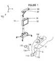
- FIG. 1is a perspective view of a computer-assisted orthopedic surgery (CADS) system
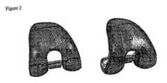
- FIG. 2is perspective view of an exemplary implant file for use in a system according to the present invention
- FIGS. 3A-Care perspective views of the implant file of FIG. 2 superimposed on a bone model in three different positions with various maps;
- FIG. 4is a planning page of the software application allowing adjustment of the implant type, size and position.
- a system according to the present inventionis configured to permit the surgeon to plan the optimal, position, size, and type of prosthesis taking into account multiple criteria. This planning is performed prior to making some or all of the bone cuts necessary to insert and accommodate the implant components and in particular, the system and components thereof are used as tools in the overall planning package that provides numerical and graphic information to the surgeon to ensure optimal selection and placement of the implant components.
- the overall systemincludes a navigation component (tool) and in particular, a navigation system.
- a computer-assisted orthopedic surgery (CAOS) system 10is schematically shown.
- the CAOS system 10is configured for performing joint replacement or resurfacing surgeries, such as knee or hip replacement surgery.
- the system 10includes a suitable position measuring device 20 that can accurately measure the position of marking elements in three dimensional space.
- the position measuring device 20can employ any type of position measuring method as may be known in the art, for example, emitter/detector or reflector systems including optic, acoustic or other wave forms, shape based recognition tracking algorithms, or video-based, mechanical, electromagnetic and radio frequency systems.
- the position measuring system 20is an optical tracking system that includes at least one camera that is in communication with a computer system 30 and is positioned to detect light reflected from a number of special light reflecting markers such as spheres or discs 50 .
- markers 50can be rigidly connected together to form reference bodies, (e.g., 100 , 110 ), and these reference bodies can be attached to bones, tools and other objects to be tracked.
- reference bodiese.g., 100 , 110
- One such device that has been found to be suitable for performing the tracking functionis the PolarisTM system from Northern Digital Inc., Ontario, Canada. However, other systems can be used also.
- the position measurement device 20is described in greater detail in a number of publications, including U.S. Pat. Nos. 5,564,437 and 6,725,082, both of which are incorporated by reference in their entirety.
- the position of the patient's bonescan be determined and tracked by attaching reference bodies 100 , 110 , which include respective markers 102 , 112 , to the bones 2 , 4 , respectively.
- the reference bodiescan be attached to bones or tools using pins or screws 104 , 114 , or various quick release mechanisms.
- the reference bodiescan also be shaped in the form of numbers (e.g., “1”, “2”, “3” . . . ) or alphabetical letters, such as “F” for Femur, “T” for Tibia, “P” for pointer, and so on, so as to avoid confusion as to which reference body should be attached to which bone or tool.
- the tracked objects and their relative positionscan be displayed on a screen (display) that is connected to the computer system 30 .
- the displayis a touch screen which can also be used for data entry.
- the position measurement device 20includes a number of different tools that are used at different locations and perform different functions as the system 10 is operated to yield optimal joint reconstruction data and information. These tools include a pointer 120 , with markers 122 , which can be used to digitize points on the surfaces of the femur 2 and tibia 4 .
- the reference bodies 100 , 110can be used for determining the position and orientation of an individual's bone in a three dimensional coordinate system 40 .
- the reference bodies 100 , 110are preferably rigid and the respective markers 102 , 112 are preferably configured to reflect infrared light. Markers 102 , 112 are sufficient to establish the position and orientation of the rigid bodies 100 , 110 within the coordinate system 40 .
- An exemplary bone model building procedureincludes the following steps: (1) morphing; (2) image matching; and (3) hybrid.
- Models of the jointcan either be built using point based methods, image-free morphing based methods, or medical image-based methods, such as those described in U.S. Pat. No. 6,385,475 to Cinquin et al, US20050101966 to Lavallee, and U.S. Pat. No. 6,205,411 to DiGioia et al. (all of which are incorporated herein by reference in their entirety).
- three dimensional geometrical surface models of the bonesare provided by image-free means.
- these modelsare obtained by adjusting a deformable model of the bone to points acquired on the bone surface. Examples of some known methods of carrying out this task can be found in the following references: (1) “Building a complete surface model from sparse data using statistical shape models: application to computer assisted knee surgery” by M. Fleute and S. Lavhui, published in Medical Image Computing And Computer-Assisted Intervention—MICCAI '98, Spinger-Verlag LNCS Series, pages 880-887, October 1998; (2) Fleute M, Lavallee S, Julliard R.
- the three dimensional shapes of the involved bonesmay be provided with image free techniques, such as using bone morphing software which is capable of extrapolating very few range data to obtain a complete surface representation of an anatomical structure (e.g., a bone).
- bone morphing softwarewhich is capable of extrapolating very few range data to obtain a complete surface representation of an anatomical structure (e.g., a bone).
- the specific details of bone morphingare set forth in the above references but in general, a complete surface model is built from sparse data using statistical shape models.
- the modelis built from a population of a number of specimen (points), such as femur or tibia points that are digitized. Data sets are registered together using an elastic registration method (e.g., the Szeliski and Lavallee method) based on octree-splines.
- PCAPrincipal component analysis
- representations of the femur and tibial bones, or a portion thereofare displayed on the screen. These models move on the screen in real time based on the motion of tracked femur and tibia.
- the systemguides the surgeon in manipulating the knee, by using the bone representations as visual aids. Knee manipulations can be preformed, preferably before the implants are installed, to quantify the original stability of the knee. For example, varus/valgus stress tests can be applied to the knee at various knee flexion angles (for example, at 0°, 20°, 70°) and the degree of laxity in each compartment or the change in alignment can be recorded for each measurement.
- the laxitiescan be recorded automatically during the manipulations on a single page since the computer can track the relative positions of the bone and in real time calculate the knee flexion angle and store the maximum change in alignment when the flexion angle is at or near a particular value (for example 20 ⁇ 5°).
- a particular valuefor example 20 ⁇ 5°.
- the systemis able to guide the surgeon in making kinematic measurements of flexion and rotations in order to quantify the soft tissues enveloping the knee joint.
- the systemis also capable of recording knee gap measurements at various knee angles, such as in extension (0°) and flexion (90°) with the knee joint distracted, so as tension is applied to the ligaments and the maximum joint spaces are quantified.
- Such systemsare described in references such as and storing these values to be used as inputs in the implant planning algorithm
- the patients' bone modelis used as an input into the implant planning algorithm.
- These modelsare typically in the form of a point or meshed based surface model consisting of points or nodes and polygons, such as triangles.
- a database of 3D implant models in the form of 3D meshed surfaceare also used as inputs. These models describe the detailed external and internal shape of the implant, where the internal shape corresponds to the surface that is in contact with the host bone.
- specific characteristicsare provided, such as antero-posterior size, medio-lateral width, 5 or 8 or more cut planes, implant peg positions and diameters, outer contours, specific discriminating areas in the form of a subset list of triangles from the meshed surface, specific surface curvature or thickness.
- This list of geometrical or surface data relative to the specificity of the implantis not exhaustive and can be provided by the implant manufacturer.
- the inventionprovides a system for planning the position and size of a prosthesis based on any criteria including those mentioned below, or simply manual selection and positioning by the surgeon.
- the systemcan indicate to the surgeon the difference in shape between the external surface of the implant and the external surface of the bone based on the model of the bone and of the implant. This can be effectively accomplished by superimposing a map on the bone or implant displayed on the screen that depicts this difference. Different spectrums of color or transparences can be used to illustrate the map.
- an optimization processexists to find in the implant data base the model which provides a best fit to the patient bone model.
- This algorithmis tailored according to a list of specific target criteria, ranked with a priority and a tolerance range.
- Geometrical criteriaaxis alignment (for example, alignment to the mechanical axis of the leg), specific angle orientation, specific cut height distances, and so on;
- Matching criteriaAlignment or centering of one implant with respect to another implant in the same joint;
- Functionality criteriaequal internal and external joint gaps (i.e.
- ligament balancingligament balancing
- cut parallelismfor example, between the tibial plateau cut and distal or posterior femoral cuts
- no residual laxity or a laxity inferior to a specific threshold(4) Morphology matching criteria: no medio-lateral overhanging (for example, adjacent to one or more of the five femoral cuts such as the distal or anterior cut), anterior cortex tangency, surface matching in specific areas, trochlear groove orientation, fitting and opening, fitting of the implant perimeter with respect to the bone contour around the bone cuts made to implant the prosthesis.
- the unknowns of the optimization problem for each implantare: (1) The implant type; (2) The implant size; and (3) The implant position: 3 translations+3 rotations.
- the system of the present inventionincludes the morphological shape of the implant compared to the shape of the anatomical bone surface in the optimization process in order to find the best fitting implant type, size and position.
- the morphological comparison between the implant 3D model and the bone 3D modelcan take place for any of the optimization criterion.
- the systemis used to help the surgeon position a femoral component for total knee arthroplasty such that the trochlear groove of the implant best matches the trochlear groove of the patient anatomy.
- the surgeoncan manually fine-tune the rotational (axial) alignment and anterior/posterior positioning of the implant with respect to multiple criteria, including boney landmarks (transepicondylar axis, posterior condylar axis, or Whiteside's line) and gap criteria (medial and lateral flexion gaps) while simultaneously visualizing the influence of the positioning on the matching of the external surface of the implant to the patents femoral groove using the map.
- the flexion of the implantis such that the femoral component anterior cut is parallel to the bone anterior cortex surface, within the range of ⁇ 3° and +5°.
- the femoral component axial rotationis such that the posterior condyles are parallel to the tibia cut for the balanced flexion position, but the orientation of the implant trochlear groove must stay within +/ ⁇ 2° from the orientation of the anatomical trochlear groove.
- the anatomic trochlear groovecan be determined by searching for the line at the deepest part of the groove in the bone model, or by asking the surgeon to draw this line with pointer.
- the implant positionis based on geometrical alignment criteria, but the size must be chosen so that the distance between the implant model and the bone model is minimized on the anterior and on the posterior surfaces.
- the global optimization algorithmis as follows:
- the final outputis the couple (t,s) and its corresponding position P(t,s) which are the optimum solution proposal.
- the “Optimize” computationis based on a regular minimization process, starting with an initial proposal, and modifying the solutions in the direction of the gradient of cost functions for each of 6 position parameters.
- Such optimization processesexist and are commonly known in the state of the art, such as the so-called Levenberg-Marquardt algorithm (for example see http://en.wikipedia.org/wiki/Levenberg-Marquardt_algorithm).
- the cost functionsare mathematical expressions of the target criteria.
- geometrical criteriaexpressed directly in the terms of target angles or target distances, the mathematical formulation is trivial because there is directly a target numerical value.
- the cost functionshave to be translated in terms of angles differences or distances differences which have to be minimized.
- the cost functionsare translated in terms distances between surfaces, which have to be minimized.
- the computation of the cost function value or discriminating score based on morphological shapemainly consists in the computation of a mean squared distance between two surfaces in predetermined areas.
- Specific surface patchesare defined on each implant 3D mesh as triangles subsets.
- a list of trianglescan represent the trochlear groove
- another setcan represent the medial anterior area and anther one the lateral anterior area of the implant.
- the algorithmcalculates the mean squared distance between predefined zones on the implant and bone surfaces, such as the femoral groove areas, the medial and lateral portions of the anterior flange, or the condyles. Obviously this could be extended to other surfaces of other joints, such as the hip joint (for example the femoral neck and head surfaces, or the acetabular fossa and rim).
- the distance from the implant surface patch to the bone surfacecan be computed from any known algorithm for surface distance computation. Finally from all the distances computed with the triangles in the implant surface patch, the Root Mean Square is computed and this gives the discriminating score for that particular patch. Any particular subsets of nodes within a surface patch may also have different weighting scores associated with them, so that particular zones within the patches may have a greater or lesser influence on the overall score for that patch.
- the final scorecan be computed from the RMS scores for all the determined patches, with further possible different weightings for each patch.
- the optimum solutionis the one with the minimum discriminating score.
- the userwill have the feedback on the score value for the optimized solution (t, s, P(t,s)), but also for the other combinations for comparison.
- this representationcan be based on distance map visualization 200 , enabling the surgeon to differentiate the areas with a good morphology matching (distance of the implant 3D mesh to the bone 3D mesh close to 0), from the areas where the implant surface is above or under the bone surface.
- the optimization processgives the following distance map: the scale can go from dark blue where the implant surface is above the bone surface (indicated at 210 in FIG. 4 and also represented by the number 4 in the key 205 of FIG. 4 ) to light red where the implant surface is below the bone surface (indicated at 220 in FIG. 4 and also represented by the number ⁇ 4 in the key 205 ). Light green colors can indicate the areas where surface of the implant most closely match the bone morphology (represented by the number 0 in the key 205 in FIG. 4 ).
- the number scale from negative four ( ⁇ 4) to positive four (+4)can correspond to the distance in millimeters that the implant is either inside or outside the bone surface, respectively, where the number zero (0) is a perfect match.
- the map 205thus provides an easy to use system for the surgeon to determine the best fit between the implant and the bone.
- the areas with a higher concentration of stipplingrepresent greater distances of the implant to the bone surface either inside or outside the bone surface, while areas with no stippling represent areas where a close fit exists between the implant and the bone.
- Areas of a lighter concentration of stipplingrepresent areas where the implant is a lesser distance either outside or inside the bone surface as depicted in the key 205 which is a color map in one embodiment where different colors represent different degrees of distance from the implant to the bone surface.
- the systemcan also take into account which areas of the bone are worn or abnormal (pathological), and treat these areas of the bone differently in the optimization algorithm or in the display of the map. For example, worn areas could have a lower weighting or can be excluded completely for the optimization area. The map could be not shown or indicated by different colors or transparencies in those areas. Determination of normal and/or pathological areas of the bone can be done in any number ways, including:
- the determination of the optimal implant type, size and position taking into account the bone morphology in different areas and with different constraintscan be also accomplished by:
- Additional methods of displaying on the screen the difference in the morphology of the native bone and the shape of the implant using a color mapinclude:
- the differences between the two displayed modelsnamely, the implant model selected from the database ( FIG. 2 ) and the bone model derived from an imaging operation ( FIGS. 3A-C ), such as bone morphing, are superimposed on one another with differences between the two models being visually highlighted so as to permit a surgeon, etc., to immediate and in real-time determine the degree of “fit” between the two models as shown in FIGS. 3A-C .
- the differenceswhich reflect a degree of distance where the implant model departs from the bone model in localized areas, can be illustrated using a color map to show the relative degree of differences.
- FIGS. 3A-Care perspective views of the implant file superimposed on a bone model in three different positions with various maps to show the degree of fit between the selected model and the bone model.
- the areas with a higher concentration of stipplingrepresent areas where the two models depart the greatest, while areas with no stippling represent areas where a close (good) fit exists between the two models. Areas of a lighter concentration of stippling represent an intermediate fit between the two models.
- One advantage of the present systemis that the user (surgeon) can load a model of a different implant model from the database and display in real time in a superimposed manner over the bone model to determine the relative degree of fit between the two. This ability to select amongst a group of stored implant models in the database, allows the surgeon to very quickly compare and evaluate a number of different implants to see which implant offers the most optimal fit for the patient in view of the patient's bone structure as displayed by the bone model.
Landscapes
- Health & Medical Sciences (AREA)
- Engineering & Computer Science (AREA)
- Surgery (AREA)
- Life Sciences & Earth Sciences (AREA)
- Medical Informatics (AREA)
- Public Health (AREA)
- Biomedical Technology (AREA)
- General Health & Medical Sciences (AREA)
- Robotics (AREA)
- Molecular Biology (AREA)
- Animal Behavior & Ethology (AREA)
- Heart & Thoracic Surgery (AREA)
- Nuclear Medicine, Radiotherapy & Molecular Imaging (AREA)
- Veterinary Medicine (AREA)
- Data Mining & Analysis (AREA)
- Databases & Information Systems (AREA)
- Pathology (AREA)
- Epidemiology (AREA)
- Primary Health Care (AREA)
- Physics & Mathematics (AREA)
- Theoretical Computer Science (AREA)
- Evolutionary Computation (AREA)
- Geometry (AREA)
- General Engineering & Computer Science (AREA)
- General Physics & Mathematics (AREA)
- Computer Hardware Design (AREA)
- Prostheses (AREA)
- Architecture (AREA)
- Software Systems (AREA)
Abstract
Description
- Lavallee—System for determining the position of a knee prosthesis US20050101966; and
- Fluete—Restoring of three-dimensional surfaces by using statistical models U.S. Pat. No. 7,227,981.
- For each implant type t (ex: t1=standard, t2=gender)
- For each implant size s (ex: from size A to size E)
- P(t,s)=Optimize (Implant_Model_t_s, rotation criteria, translation criteria, list of constraints).
- Discriminating_Score(t,s)=Scores (P(t,s), Morpholocial_Discriminating_Criteria)
- If Discriminating_Score(t,s)<Optimum_Score,
- Then Optimum_Score=Discriminating_Score(t,s)
- And Optimum_Solution=(t, s, P(t,s)).
- Then Optimum_Score=Discriminating_Score(t,s)
- Asking the surgeon to identify with the pointer;
- Using surface curvature and shape of the bone itself;
- By comparing the reconstructed bone surface with the generic morphing model using only global and not local deformation;
- Identify areas which have undergone the most important deformations from the generic morphing model once the bone morphing has been performed;
- Using the modes of variation;
- By comparing it to the contra-lateral joint (for example, when pre-operative or intra-operative imaging is performed);
- Using information of the measured kinematics (e.g. laxity); and
- By using the relative bone orientations and global anatomy such as the mechanical axis to predict worn areas.
- Determining initially a subset of optimal implant sizes and positions for different implant types and then choosing the particular implant type that minimizes the difference between the bone surface and external implant surface in specific local areas;
- Providing global numerical values such as the average and maximum deviation between the bone and the model in certain areas for a subset of implants in the database, to help the surgeon select which implant to use;
- Find the best fitting implant type, size and position minimizing the distances between the bone shape and external implant shape while maintaining functional constraints such as alignment to the mechanical axis, troclear groove, epicondylar axis rectangular flexion spaces, patellar trajectory, etc.;
- Using the ratio of width to AP dimension to best match the implant to the bone;
- Using the contours of the virtual cuts compared to the contours of the implant cuts (especially the shape of the anterior cut contours);
- Matching the AP dimension with the implant size and then selecting the implant that minimize the degree of overhang or exposed bone at the perimeter of the implant for at least two different types;
- Using contralateral joint if not worn (image based); and
- Using the patients gender or race as an initial input to selecting which prosthesis types to compare.
- Color proportional to distance;
- Implant in semitransparent color superimposed over bone surface with the shade of transparency proportional to the distance to the bone;
- “scanner-like slices” in sagittal, frontal and axial planes showing the profile of the bone and the profile of the implant external surface;
- using the direction normal to the implant or bone surface;
- In some cases the bone may also protrude from the implant which can also be represented in different color or tone than for bone which is inside the prosthesis;
- Using different representations for areas of the bone model that are normal and pathological;
- Using different representations for areas of the Bone Morphing Model that are not accurate; and
- Displaying difference between operated knee and contra-lateral knee morphology taking into account worn and not worn surfaces.
Claims (20)
Priority Applications (2)
| Application Number | Priority Date | Filing Date | Title |
|---|---|---|---|
| US13/540,134US8990052B2 (en) | 2006-12-12 | 2012-07-02 | System and method for determining an optimal type and position of an implant |
| US14/666,001US9684768B2 (en) | 2006-12-12 | 2015-03-23 | System and method for determining an optimal type and position of an implant |
Applications Claiming Priority (3)
| Application Number | Priority Date | Filing Date | Title |
|---|---|---|---|
| US86966806P | 2006-12-12 | 2006-12-12 | |
| US11/955,160US8214016B2 (en) | 2006-12-12 | 2007-12-12 | System and method for determining an optimal type and position of an implant |
| US13/540,134US8990052B2 (en) | 2006-12-12 | 2012-07-02 | System and method for determining an optimal type and position of an implant |
Related Parent Applications (1)
| Application Number | Title | Priority Date | Filing Date |
|---|---|---|---|
| US11/955,160ContinuationUS8214016B2 (en) | 2006-12-12 | 2007-12-12 | System and method for determining an optimal type and position of an implant |
Related Child Applications (1)
| Application Number | Title | Priority Date | Filing Date |
|---|---|---|---|
| US14/666,001ContinuationUS9684768B2 (en) | 2006-12-12 | 2015-03-23 | System and method for determining an optimal type and position of an implant |
Publications (2)
| Publication Number | Publication Date |
|---|---|
| US20120271599A1 US20120271599A1 (en) | 2012-10-25 |
| US8990052B2true US8990052B2 (en) | 2015-03-24 |
Family
ID=40137283
Family Applications (3)
| Application Number | Title | Priority Date | Filing Date |
|---|---|---|---|
| US11/955,160Active2030-12-03US8214016B2 (en) | 2006-12-12 | 2007-12-12 | System and method for determining an optimal type and position of an implant |
| US13/540,134Active2028-10-30US8990052B2 (en) | 2006-12-12 | 2012-07-02 | System and method for determining an optimal type and position of an implant |
| US14/666,001ActiveUS9684768B2 (en) | 2006-12-12 | 2015-03-23 | System and method for determining an optimal type and position of an implant |
Family Applications Before (1)
| Application Number | Title | Priority Date | Filing Date |
|---|---|---|---|
| US11/955,160Active2030-12-03US8214016B2 (en) | 2006-12-12 | 2007-12-12 | System and method for determining an optimal type and position of an implant |
Family Applications After (1)
| Application Number | Title | Priority Date | Filing Date |
|---|---|---|---|
| US14/666,001ActiveUS9684768B2 (en) | 2006-12-12 | 2015-03-23 | System and method for determining an optimal type and position of an implant |
Country Status (1)
| Country | Link |
|---|---|
| US (3) | US8214016B2 (en) |
Cited By (15)
| Publication number | Priority date | Publication date | Assignee | Title |
|---|---|---|---|---|
| US20170273549A1 (en)* | 2014-05-09 | 2017-09-28 | X-Biomedical | Portable Surgical Methods, Systems, and Apparatus |
| US20180132937A1 (en)* | 2015-04-28 | 2018-05-17 | Brainlab Ag | Method and device for determining geometric parameters for total knee replacement surgery |
| US10285683B2 (en) | 2015-03-24 | 2019-05-14 | Omnilife Science, Inc | Orthopedic joint distraction device |
| US10987176B2 (en) | 2018-06-19 | 2021-04-27 | Tornier, Inc. | Virtual guidance for orthopedic surgical procedures |
| US11166781B2 (en) | 2018-04-23 | 2021-11-09 | Mako Surgical Corp. | System, method and software program for aiding in positioning of a camera relative to objects in a surgical environment |
| US11376054B2 (en) | 2018-04-17 | 2022-07-05 | Stryker European Operations Limited | On-demand implant customization in a surgical setting |
| US20240217115A1 (en)* | 2022-12-28 | 2024-07-04 | Kawasaki Jukogyo Kabushiki Kaisha | Robotic surgical system and method for controlling robotic surgical system |
| US12051198B2 (en) | 2019-03-29 | 2024-07-30 | Howmedica Osteonics Corp. | Pre-morbid characterization of anatomical object using statistical shape modeling (SSM) |
| US12070272B2 (en) | 2013-10-10 | 2024-08-27 | Stryker European Operations Limited | Methods, systems and devices for pre-operatively planned shoulder surgery guides and implants |
| US12097129B2 (en) | 2013-11-13 | 2024-09-24 | Tornier Sas | Shoulder patient specific instrument |
| US12133688B2 (en) | 2013-11-08 | 2024-11-05 | Stryker European Operations Limited | Methods, systems and devices for pre-operatively planned adaptive glenoid implants |
| US12232744B2 (en) | 2019-07-15 | 2025-02-25 | Stryker Corporation | Robotic hand-held surgical instrument systems and methods |
| US12349979B2 (en) | 2019-10-29 | 2025-07-08 | Howmedica Osteonics Corp. | Use of bony landmarks in computerized orthopedic surgical planning |
| US12383334B2 (en) | 2018-12-12 | 2025-08-12 | Howmedica Osteonics Corp. | Orthopedic surgical planning based on soft tissue and bone density modeling |
| US12441001B2 (en)* | 2022-12-28 | 2025-10-14 | Kawasaki Jukogyo Kabushiki Kaisha | Robotic surgical system and method for controlling robotic surgical system |
Families Citing this family (226)
| Publication number | Priority date | Publication date | Assignee | Title |
|---|---|---|---|---|
| US8545569B2 (en) | 2001-05-25 | 2013-10-01 | Conformis, Inc. | Patient selectable knee arthroplasty devices |
| US8480754B2 (en) | 2001-05-25 | 2013-07-09 | Conformis, Inc. | Patient-adapted and improved articular implants, designs and related guide tools |
| US9603711B2 (en) | 2001-05-25 | 2017-03-28 | Conformis, Inc. | Patient-adapted and improved articular implants, designs and related guide tools |
| US8556983B2 (en) | 2001-05-25 | 2013-10-15 | Conformis, Inc. | Patient-adapted and improved orthopedic implants, designs and related tools |
| US8882847B2 (en) | 2001-05-25 | 2014-11-11 | Conformis, Inc. | Patient selectable knee joint arthroplasty devices |
| US20030055502A1 (en) | 2001-05-25 | 2003-03-20 | Philipp Lang | Methods and compositions for articular resurfacing |
| US7534263B2 (en) | 2001-05-25 | 2009-05-19 | Conformis, Inc. | Surgical tools facilitating increased accuracy, speed and simplicity in performing joint arthroplasty |
| US8083745B2 (en) | 2001-05-25 | 2011-12-27 | Conformis, Inc. | Surgical tools for arthroplasty |
| US7468075B2 (en) | 2001-05-25 | 2008-12-23 | Conformis, Inc. | Methods and compositions for articular repair |
| US8735773B2 (en) | 2007-02-14 | 2014-05-27 | Conformis, Inc. | Implant device and method for manufacture |
| US8771365B2 (en) | 2009-02-25 | 2014-07-08 | Conformis, Inc. | Patient-adapted and improved orthopedic implants, designs, and related tools |
| US8617242B2 (en) | 2001-05-25 | 2013-12-31 | Conformis, Inc. | Implant device and method for manufacture |
| US7635390B1 (en) | 2000-01-14 | 2009-12-22 | Marctec, Llc | Joint replacement component having a modular articulating surface |
| DE60136474D1 (en) | 2000-09-14 | 2008-12-18 | Univ R | ASSESSMENT OF THE CONDITION OF A JOINT AND LOSS OF CARTEL TISSUE |
| US8439926B2 (en) | 2001-05-25 | 2013-05-14 | Conformis, Inc. | Patient selectable joint arthroplasty devices and surgical tools |
| US7708741B1 (en) | 2001-08-28 | 2010-05-04 | Marctec, Llc | Method of preparing bones for knee replacement surgery |
| US9155544B2 (en) | 2002-03-20 | 2015-10-13 | P Tech, Llc | Robotic systems and methods |
| JP2006501977A (en) | 2002-10-07 | 2006-01-19 | コンフォーミス・インコーポレイテッド | Minimally invasive joint implant with a three-dimensional profile that conforms to the joint surface |
| JP2006505366A (en) | 2002-11-07 | 2006-02-16 | コンフォーミス・インコーポレイテッド | Method of determining meniscus size and shape and devised treatment |
| US8623026B2 (en) | 2006-02-06 | 2014-01-07 | Conformis, Inc. | Patient selectable joint arthroplasty devices and surgical tools incorporating anatomical relief |
| CN105030296A (en) | 2006-02-06 | 2015-11-11 | 康复米斯公司 | Patient selectable joint arthroplasty devices and surgical tools |
| US9808262B2 (en) | 2006-02-15 | 2017-11-07 | Howmedica Osteonics Corporation | Arthroplasty devices and related methods |
| CA2642615A1 (en) | 2006-02-15 | 2007-08-30 | Otismed Corp | Arthroplasty jigs and related methods |
| US8591516B2 (en) | 2006-02-27 | 2013-11-26 | Biomet Manufacturing, Llc | Patient-specific orthopedic instruments |
| US20150335438A1 (en) | 2006-02-27 | 2015-11-26 | Biomet Manufacturing, Llc. | Patient-specific augments |
| US8377066B2 (en) | 2006-02-27 | 2013-02-19 | Biomet Manufacturing Corp. | Patient-specific elbow guides and associated methods |
| US7967868B2 (en)* | 2007-04-17 | 2011-06-28 | Biomet Manufacturing Corp. | Patient-modified implant and associated method |
| US8133234B2 (en) | 2006-02-27 | 2012-03-13 | Biomet Manufacturing Corp. | Patient specific acetabular guide and method |
| US8535387B2 (en) | 2006-02-27 | 2013-09-17 | Biomet Manufacturing, Llc | Patient-specific tools and implants |
| US8070752B2 (en) | 2006-02-27 | 2011-12-06 | Biomet Manufacturing Corp. | Patient specific alignment guide and inter-operative adjustment |
| US9918740B2 (en) | 2006-02-27 | 2018-03-20 | Biomet Manufacturing, Llc | Backup surgical instrument system and method |
| US9339278B2 (en) | 2006-02-27 | 2016-05-17 | Biomet Manufacturing, Llc | Patient-specific acetabular guides and associated instruments |
| US8473305B2 (en) | 2007-04-17 | 2013-06-25 | Biomet Manufacturing Corp. | Method and apparatus for manufacturing an implant |
| US8407067B2 (en) | 2007-04-17 | 2013-03-26 | Biomet Manufacturing Corp. | Method and apparatus for manufacturing an implant |
| US8241293B2 (en) | 2006-02-27 | 2012-08-14 | Biomet Manufacturing Corp. | Patient specific high tibia osteotomy |
| US9173661B2 (en) | 2006-02-27 | 2015-11-03 | Biomet Manufacturing, Llc | Patient specific alignment guide with cutting surface and laser indicator |
| US8568487B2 (en) | 2006-02-27 | 2013-10-29 | Biomet Manufacturing, Llc | Patient-specific hip joint devices |
| US8092465B2 (en) | 2006-06-09 | 2012-01-10 | Biomet Manufacturing Corp. | Patient specific knee alignment guide and associated method |
| US8608748B2 (en) | 2006-02-27 | 2013-12-17 | Biomet Manufacturing, Llc | Patient specific guides |
| US9907659B2 (en) | 2007-04-17 | 2018-03-06 | Biomet Manufacturing, Llc | Method and apparatus for manufacturing an implant |
| US9113971B2 (en) | 2006-02-27 | 2015-08-25 | Biomet Manufacturing, Llc | Femoral acetabular impingement guide |
| US8603180B2 (en) | 2006-02-27 | 2013-12-10 | Biomet Manufacturing, Llc | Patient-specific acetabular alignment guides |
| US9289253B2 (en) | 2006-02-27 | 2016-03-22 | Biomet Manufacturing, Llc | Patient-specific shoulder guide |
| US8282646B2 (en) | 2006-02-27 | 2012-10-09 | Biomet Manufacturing Corp. | Patient specific knee alignment guide and associated method |
| US8864769B2 (en) | 2006-02-27 | 2014-10-21 | Biomet Manufacturing, Llc | Alignment guides with patient-specific anchoring elements |
| US10278711B2 (en) | 2006-02-27 | 2019-05-07 | Biomet Manufacturing, Llc | Patient-specific femoral guide |
| US8298237B2 (en) | 2006-06-09 | 2012-10-30 | Biomet Manufacturing Corp. | Patient-specific alignment guide for multiple incisions |
| US8858561B2 (en) | 2006-06-09 | 2014-10-14 | Blomet Manufacturing, LLC | Patient-specific alignment guide |
| US8608749B2 (en) | 2006-02-27 | 2013-12-17 | Biomet Manufacturing, Llc | Patient-specific acetabular guides and associated instruments |
| US9345548B2 (en) | 2006-02-27 | 2016-05-24 | Biomet Manufacturing, Llc | Patient-specific pre-operative planning |
| PL2023812T3 (en) | 2006-05-19 | 2017-07-31 | The Queen's Medical Center | Motion tracking system for real time adaptive imaging and spectroscopy |
| US9795399B2 (en) | 2006-06-09 | 2017-10-24 | Biomet Manufacturing, Llc | Patient-specific knee alignment guide and associated method |
| US8460302B2 (en) | 2006-12-18 | 2013-06-11 | Otismed Corporation | Arthroplasty devices and related methods |
| WO2008157412A2 (en) | 2007-06-13 | 2008-12-24 | Conformis, Inc. | Surgical cutting guide |
| EP2200530A2 (en)* | 2007-09-12 | 2010-06-30 | Nobel Biocare Services AG | Method and system for planning a medical procedure and generating data related to said medical procedure |
| US8265949B2 (en) | 2007-09-27 | 2012-09-11 | Depuy Products, Inc. | Customized patient surgical plan |
| EP2194889B1 (en) | 2007-09-30 | 2015-09-23 | DePuy Products, Inc. | Customized patient-specific orthopaedic surgical instrumentation |
| US8357111B2 (en) | 2007-09-30 | 2013-01-22 | Depuy Products, Inc. | Method and system for designing patient-specific orthopaedic surgical instruments |
| US8460303B2 (en) | 2007-10-25 | 2013-06-11 | Otismed Corporation | Arthroplasty systems and devices, and related methods |
| USD642263S1 (en) | 2007-10-25 | 2011-07-26 | Otismed Corporation | Arthroplasty jig blank |
| US10582934B2 (en) | 2007-11-27 | 2020-03-10 | Howmedica Osteonics Corporation | Generating MRI images usable for the creation of 3D bone models employed to make customized arthroplasty jigs |
| AU2008335328B2 (en) | 2007-12-06 | 2014-11-27 | Smith & Nephew, Inc. | Systems and methods for determining the mechanical axis of a femur |
| US8160345B2 (en) | 2008-04-30 | 2012-04-17 | Otismed Corporation | System and method for image segmentation in generating computer models of a joint to undergo arthroplasty |
| US8480679B2 (en) | 2008-04-29 | 2013-07-09 | Otismed Corporation | Generation of a computerized bone model representative of a pre-degenerated state and useable in the design and manufacture of arthroplasty devices |
| US8311306B2 (en) | 2008-04-30 | 2012-11-13 | Otismed Corporation | System and method for image segmentation in generating computer models of a joint to undergo arthroplasty |
| US8545509B2 (en) | 2007-12-18 | 2013-10-01 | Otismed Corporation | Arthroplasty system and related methods |
| US8617171B2 (en) | 2007-12-18 | 2013-12-31 | Otismed Corporation | Preoperatively planning an arthroplasty procedure and generating a corresponding patient specific arthroplasty resection guide |
| US8221430B2 (en) | 2007-12-18 | 2012-07-17 | Otismed Corporation | System and method for manufacturing arthroplasty jigs |
| US8737700B2 (en) | 2007-12-18 | 2014-05-27 | Otismed Corporation | Preoperatively planning an arthroplasty procedure and generating a corresponding patient specific arthroplasty resection guide |
| US8777875B2 (en) | 2008-07-23 | 2014-07-15 | Otismed Corporation | System and method for manufacturing arthroplasty jigs having improved mating accuracy |
| US8715291B2 (en) | 2007-12-18 | 2014-05-06 | Otismed Corporation | Arthroplasty system and related methods |
| ES2595366T3 (en) | 2008-01-09 | 2016-12-29 | Stryker European Holdings I, Llc | Computer-assisted stereotactic surgery system based on a three-dimensional visualization |
| GB0803725D0 (en)* | 2008-02-29 | 2008-04-09 | Depuy Int Ltd | Surgical apparatus and procedure |
| US8734455B2 (en) | 2008-02-29 | 2014-05-27 | Otismed Corporation | Hip resurfacing surgical guide tool |
| WO2009111626A2 (en) | 2008-03-05 | 2009-09-11 | Conformis, Inc. | Implants for altering wear patterns of articular surfaces |
| WO2009140294A1 (en) | 2008-05-12 | 2009-11-19 | Conformis, Inc. | Devices and methods for treatment of facet and other joints |
| US8617175B2 (en) | 2008-12-16 | 2013-12-31 | Otismed Corporation | Unicompartmental customized arthroplasty cutting jigs and methods of making the same |
| US8170641B2 (en) | 2009-02-20 | 2012-05-01 | Biomet Manufacturing Corp. | Method of imaging an extremity of a patient |
| WO2010099231A2 (en) | 2009-02-24 | 2010-09-02 | Conformis, Inc. | Automated systems for manufacturing patient-specific orthopedic implants and instrumentation |
| SG10201401326SA (en) | 2009-04-16 | 2014-10-30 | Conformis Inc | Patient-specific joint arthroplasty devices for ligament repair |
| US8794977B2 (en)* | 2009-04-29 | 2014-08-05 | Lifemodeler, Inc. | Implant training system |
| DE102009028503B4 (en) | 2009-08-13 | 2013-11-14 | Biomet Manufacturing Corp. | Resection template for the resection of bones, method for producing such a resection template and operation set for performing knee joint surgery |
| GB0918826D0 (en) | 2009-10-27 | 2009-12-09 | Depuy Orthopaedie Gmbh | Intra-operative surgical plan changing |
| US8632547B2 (en) | 2010-02-26 | 2014-01-21 | Biomet Sports Medicine, Llc | Patient-specific osteotomy devices and methods |
| AU2011200764B2 (en)* | 2010-03-01 | 2013-06-13 | Stryker European Operations Holdings Llc | Computer assisted surgery system |
| US10588647B2 (en)* | 2010-03-01 | 2020-03-17 | Stryker European Holdings I, Llc | Computer assisted surgery system |
| US9066727B2 (en) | 2010-03-04 | 2015-06-30 | Materialise Nv | Patient-specific computed tomography guides |
| AU2011239570A1 (en) | 2010-04-14 | 2012-11-01 | Smith & Nephew, Inc. | Systems and methods for patient- based computer assisted surgical procedures |
| US9386994B2 (en) | 2010-06-11 | 2016-07-12 | Smith & Nephew, Inc. | Patient-matched instruments |
| US8908937B2 (en) | 2010-07-08 | 2014-12-09 | Biomet Manufacturing, Llc | Method and device for digital image templating |
| US9161821B2 (en) | 2010-07-08 | 2015-10-20 | DePuy Synthes Products, Inc. | Advanced bone marker and custom implants |
| US9517107B2 (en) | 2010-07-16 | 2016-12-13 | Stryker European Holdings I, Llc | Surgical targeting system and method |
| AU2011289154B2 (en)* | 2010-08-13 | 2016-06-09 | Smith & Nephew, Inc. | Systems and methods for optimizing parameters of orthopaedic procedures |
| WO2012021857A2 (en)* | 2010-08-13 | 2012-02-16 | Mason James Bettenga | Surgical guides |
| US9271744B2 (en) | 2010-09-29 | 2016-03-01 | Biomet Manufacturing, Llc | Patient-specific guide for partial acetabular socket replacement |
| US9968376B2 (en) | 2010-11-29 | 2018-05-15 | Biomet Manufacturing, Llc | Patient-specific orthopedic instruments |
| US8917290B2 (en) | 2011-01-31 | 2014-12-23 | Biomet Manufacturing, Llc | Digital image templating |
| WO2012112694A2 (en)* | 2011-02-15 | 2012-08-23 | Conformis, Inc. | Medeling, analyzing and using anatomical data for patient-adapted implants. designs, tools and surgical procedures |
| US9241745B2 (en) | 2011-03-07 | 2016-01-26 | Biomet Manufacturing, Llc | Patient-specific femoral version guide |
| US9241772B2 (en) | 2011-03-17 | 2016-01-26 | Brainlab Ag | Method for preparing the reconstruction of a damaged bone structure |
| US8715289B2 (en) | 2011-04-15 | 2014-05-06 | Biomet Manufacturing, Llc | Patient-specific numerically controlled instrument |
| US9675400B2 (en) | 2011-04-19 | 2017-06-13 | Biomet Manufacturing, Llc | Patient-specific fracture fixation instrumentation and method |
| US8956364B2 (en) | 2011-04-29 | 2015-02-17 | Biomet Manufacturing, Llc | Patient-specific partial knee guides and other instruments |
| US8668700B2 (en) | 2011-04-29 | 2014-03-11 | Biomet Manufacturing, Llc | Patient-specific convertible guides |
| US8532807B2 (en) | 2011-06-06 | 2013-09-10 | Biomet Manufacturing, Llc | Pre-operative planning and manufacturing method for orthopedic procedure |
| US9084618B2 (en) | 2011-06-13 | 2015-07-21 | Biomet Manufacturing, Llc | Drill guides for confirming alignment of patient-specific alignment guides |
| WO2012173890A2 (en) | 2011-06-16 | 2012-12-20 | Smith & Nephew, Inc. | Surgical alignment using references |
| US8764760B2 (en) | 2011-07-01 | 2014-07-01 | Biomet Manufacturing, Llc | Patient-specific bone-cutting guidance instruments and methods |
| US20130001121A1 (en) | 2011-07-01 | 2013-01-03 | Biomet Manufacturing Corp. | Backup kit for a patient-specific arthroplasty kit assembly |
| US10540479B2 (en) | 2011-07-15 | 2020-01-21 | Stephen B. Murphy | Surgical planning system and method |
| US10102309B2 (en) | 2011-07-20 | 2018-10-16 | Smith & Nephew, Inc. | Systems and methods for optimizing fit of an implant to anatomy |
| US8597365B2 (en) | 2011-08-04 | 2013-12-03 | Biomet Manufacturing, Llc | Patient-specific pelvic implants for acetabular reconstruction |
| WO2013032933A2 (en) | 2011-08-26 | 2013-03-07 | Kinecticor, Inc. | Methods, systems, and devices for intra-scan motion correction |
| US9066734B2 (en) | 2011-08-31 | 2015-06-30 | Biomet Manufacturing, Llc | Patient-specific sacroiliac guides and associated methods |
| US9295497B2 (en) | 2011-08-31 | 2016-03-29 | Biomet Manufacturing, Llc | Patient-specific sacroiliac and pedicle guides |
| US9386993B2 (en) | 2011-09-29 | 2016-07-12 | Biomet Manufacturing, Llc | Patient-specific femoroacetabular impingement instruments and methods |
| US9554910B2 (en) | 2011-10-27 | 2017-01-31 | Biomet Manufacturing, Llc | Patient-specific glenoid guide and implants |
| KR20130046337A (en) | 2011-10-27 | 2013-05-07 | 삼성전자주식회사 | Multi-view device and contol method thereof, display apparatus and contol method thereof, and display system |
| US9451973B2 (en) | 2011-10-27 | 2016-09-27 | Biomet Manufacturing, Llc | Patient specific glenoid guide |
| US9301812B2 (en) | 2011-10-27 | 2016-04-05 | Biomet Manufacturing, Llc | Methods for patient-specific shoulder arthroplasty |
| WO2013062848A1 (en) | 2011-10-27 | 2013-05-02 | Biomet Manufacturing Corporation | Patient-specific glenoid guides |
| DE102011119073A1 (en)* | 2011-11-15 | 2013-05-16 | Fiagon Gmbh | Registration method, position detection system and scanning instrument |
| US10314653B2 (en) | 2011-12-29 | 2019-06-11 | Mako Surgical Corp. | Systems and methods for prosthetic component orientation |
| US9237950B2 (en) | 2012-02-02 | 2016-01-19 | Biomet Manufacturing, Llc | Implant with patient-specific porous structure |
| WO2013116812A1 (en) | 2012-02-03 | 2013-08-08 | Orthohub, Inc. | External fixator deformity correction systems and methods |
| US11331149B2 (en) | 2012-05-16 | 2022-05-17 | Feops Nv | Method and system for determining a risk of hemodynamic compromise after cardiac intervention |
| ES2684140T3 (en) | 2012-05-23 | 2018-10-01 | Stryker European Holdings I, Llc | Measurement of the length of a locking screw |
| EP2852337B1 (en)* | 2012-05-23 | 2019-08-14 | Stryker European Holdings I, LLC | Entry portal navigation |
| US9675471B2 (en) | 2012-06-11 | 2017-06-13 | Conformis, Inc. | Devices, techniques and methods for assessing joint spacing, balancing soft tissues and obtaining desired kinematics for joint implant components |
| US9468502B2 (en)* | 2012-08-31 | 2016-10-18 | Smith & Nephew, Inc. | Patient specific implant positioning |
| US10039606B2 (en) | 2012-09-27 | 2018-08-07 | Stryker European Holdings I, Llc | Rotational position determination |
| US9402637B2 (en) | 2012-10-11 | 2016-08-02 | Howmedica Osteonics Corporation | Customized arthroplasty cutting guides and surgical methods using the same |
| US9060788B2 (en) | 2012-12-11 | 2015-06-23 | Biomet Manufacturing, Llc | Patient-specific acetabular guide for anterior approach |
| US9204977B2 (en) | 2012-12-11 | 2015-12-08 | Biomet Manufacturing, Llc | Patient-specific acetabular guide for anterior approach |
| US10327708B2 (en) | 2013-01-24 | 2019-06-25 | Kineticor, Inc. | Systems, devices, and methods for tracking and compensating for patient motion during a medical imaging scan |
| US9717461B2 (en) | 2013-01-24 | 2017-08-01 | Kineticor, Inc. | Systems, devices, and methods for tracking and compensating for patient motion during a medical imaging scan |
| US9305365B2 (en) | 2013-01-24 | 2016-04-05 | Kineticor, Inc. | Systems, devices, and methods for tracking moving targets |
| US9161799B2 (en) | 2013-01-28 | 2015-10-20 | Warsaw Orthopedic, Inc. | Surgical implant system and method |
| CN109008972A (en) | 2013-02-01 | 2018-12-18 | 凯内蒂科尔股份有限公司 | The motion tracking system of real-time adaptive motion compensation in biomedical imaging |
| US9204937B2 (en) | 2013-02-19 | 2015-12-08 | Stryker Trauma Gmbh | Software for use with deformity correction |
| EP2974690B1 (en)* | 2013-03-11 | 2019-01-09 | Fujitsu Limited | Program for design of dental prostheses, device for design of dental prostheses, and method for design of dental prostheses |
| US9839438B2 (en) | 2013-03-11 | 2017-12-12 | Biomet Manufacturing, Llc | Patient-specific glenoid guide with a reusable guide holder |
| US9579107B2 (en) | 2013-03-12 | 2017-02-28 | Biomet Manufacturing, Llc | Multi-point fit for patient specific guide |
| US9498233B2 (en) | 2013-03-13 | 2016-11-22 | Biomet Manufacturing, Llc. | Universal acetabular guide and associated hardware |
| US9826981B2 (en) | 2013-03-13 | 2017-11-28 | Biomet Manufacturing, Llc | Tangential fit of patient-specific guides |
| US10452238B2 (en) | 2013-03-15 | 2019-10-22 | Blue Belt Technologies, Inc. | Systems and methods for determining a position for placing of a joint prosthesis |
| US9517145B2 (en) | 2013-03-15 | 2016-12-13 | Biomet Manufacturing, Llc | Guide alignment system and method |
| EP2967813A4 (en)* | 2013-03-15 | 2016-11-09 | Conformis Inc | KINETICALLY PARAMETRIC MODELING FOR IMPLANTS, TOOLS AND SURGICAL PROCEDURES ADAPTED TO THE PATIENT |
| DE102013214067A1 (en) | 2013-07-17 | 2015-01-22 | Fiagon Gmbh | Device and method for connecting a medical instrument to a position detection system |
| DE102013215395A1 (en) | 2013-08-05 | 2015-02-05 | Fiagon Gmbh | System for the reconstruction of symmetrical body parts |
| CA3175298A1 (en)* | 2013-10-15 | 2015-04-23 | Mohamed Rashwan Mahfouz | Bone reconstruction and orthopedic implants |
| US20150112349A1 (en) | 2013-10-21 | 2015-04-23 | Biomet Manufacturing, Llc | Ligament Guide Registration |
| DE102013222230A1 (en) | 2013-10-31 | 2015-04-30 | Fiagon Gmbh | Surgical instrument |
| WO2015081025A1 (en) | 2013-11-29 | 2015-06-04 | The Johns Hopkins University | Cranial reference mount |
| US20150202045A1 (en)* | 2014-01-23 | 2015-07-23 | Bespa, Inc | Bone Implant Apparatus and Method |
| US10420611B2 (en)* | 2014-03-05 | 2019-09-24 | Blue Belt Technologies, Inc. | Computer-aided prosthesis alignment |
| WO2015148391A1 (en) | 2014-03-24 | 2015-10-01 | Thomas Michael Ernst | Systems, methods, and devices for removing prospective motion correction from medical imaging scans |
| US10282488B2 (en) | 2014-04-25 | 2019-05-07 | Biomet Manufacturing, Llc | HTO guide with optional guided ACL/PCL tunnels |
| US9408616B2 (en) | 2014-05-12 | 2016-08-09 | Biomet Manufacturing, Llc | Humeral cut guide |
| US9561040B2 (en) | 2014-06-03 | 2017-02-07 | Biomet Manufacturing, Llc | Patient-specific glenoid depth control |
| US9839436B2 (en) | 2014-06-03 | 2017-12-12 | Biomet Manufacturing, Llc | Patient-specific glenoid depth control |
| EP3188660A4 (en) | 2014-07-23 | 2018-05-16 | Kineticor, Inc. | Systems, devices, and methods for tracking and compensating for patient motion during a medical imaging scan |
| US9795495B1 (en)* | 2014-08-23 | 2017-10-24 | Timothy Ray Miller | Instrumentation and methods for knee arthroplasty |
| US9833245B2 (en) | 2014-09-29 | 2017-12-05 | Biomet Sports Medicine, Llc | Tibial tubercule osteotomy |
| US9826994B2 (en) | 2014-09-29 | 2017-11-28 | Biomet Manufacturing, Llc | Adjustable glenoid pin insertion guide |
| EP3223752A4 (en) | 2014-11-24 | 2018-09-12 | The Johns Hopkins University | A cutting machine for resizing raw implants during surgery |
| WO2016086054A1 (en) | 2014-11-24 | 2016-06-02 | The Johns Hopkins University | Computer-assisted cranioplasty |
| EP4394797A3 (en) | 2014-12-01 | 2024-12-11 | Blue Belt Technologies, Inc. | Image free implant revision surgery |
| WO2016102025A1 (en)* | 2014-12-24 | 2016-06-30 | Mobelife N.V. | Bone implant and a method for its manufacture comprising generating a plurality of fixation configurations |
| EP3247300B1 (en) | 2015-01-09 | 2020-07-15 | Azevedo Da Silva, Sara Isabel | Orthopedic surgery planning system |
| US9931168B2 (en) | 2015-01-12 | 2018-04-03 | Biomet Manufacuturing. LLC | Plan implementation |
| US9820868B2 (en) | 2015-03-30 | 2017-11-21 | Biomet Manufacturing, Llc | Method and apparatus for a pin apparatus |
| US10568647B2 (en) | 2015-06-25 | 2020-02-25 | Biomet Manufacturing, Llc | Patient-specific humeral guide designs |
| US10226262B2 (en) | 2015-06-25 | 2019-03-12 | Biomet Manufacturing, Llc | Patient-specific humeral guide designs |
| US9943247B2 (en) | 2015-07-28 | 2018-04-17 | The University Of Hawai'i | Systems, devices, and methods for detecting false movements for motion correction during a medical imaging scan |
| US9532845B1 (en)* | 2015-08-11 | 2017-01-03 | ITKR Software LLC | Methods for facilitating individualized kinematically aligned total knee replacements and devices thereof |
| AU2016316683B2 (en) | 2015-09-04 | 2020-07-23 | The Johns Hopkins University | Low-profile intercranial device |
| US10082384B1 (en) | 2015-09-10 | 2018-09-25 | Stryker European Holdings I, Llc | Systems and methods for detecting fixation frame parameters |
| US10191302B2 (en) | 2015-09-23 | 2019-01-29 | Ohio State Innovation Foundation | Contact lens comprising lenticular-like curve |
| ES2969255T3 (en) | 2015-09-23 | 2024-05-17 | Ohio State Innovation Foundation | Contact lens comprising a lenticular in an upper portion of the contact lens |
| US10058393B2 (en) | 2015-10-21 | 2018-08-28 | P Tech, Llc | Systems and methods for navigation and visualization |
| US10716515B2 (en) | 2015-11-23 | 2020-07-21 | Kineticor, Inc. | Systems, devices, and methods for tracking and compensating for patient motion during a medical imaging scan |
| US10991070B2 (en)* | 2015-12-18 | 2021-04-27 | OrthoGrid Systems, Inc | Method of providing surgical guidance |
| US10010372B1 (en) | 2016-01-06 | 2018-07-03 | Paul Beck | Marker Positioning Apparatus |
| US10004564B1 (en) | 2016-01-06 | 2018-06-26 | Paul Beck | Accurate radiographic calibration using multiple images |
| WO2017151863A1 (en) | 2016-03-02 | 2017-09-08 | Think Surgical, Inc. | Automated arthroplasty planning |
| US10010346B2 (en) | 2016-04-20 | 2018-07-03 | Stryker European Holdings I, Llc | Ring hole planning for external fixation frames |
| US10251705B2 (en) | 2016-06-02 | 2019-04-09 | Stryker European Holdings I, Llc | Software for use with deformity correction |
| US10722310B2 (en) | 2017-03-13 | 2020-07-28 | Zimmer Biomet CMF and Thoracic, LLC | Virtual surgery planning system and method |
| US10864044B2 (en) | 2017-03-14 | 2020-12-15 | Smith & Nephew, Inc. | Systems and methods for measuring bone joint laxity |
| US20180268614A1 (en)* | 2017-03-16 | 2018-09-20 | General Electric Company | Systems and methods for aligning pmi object on a model |
| US11166764B2 (en) | 2017-07-27 | 2021-11-09 | Carlsmed, Inc. | Systems and methods for assisting and augmenting surgical procedures |
| US11320673B2 (en) | 2017-09-01 | 2022-05-03 | Ohio State Innovation Foundation | Soft contact lens comprising a lenticular in a superior portion of the contact lens with enhanced tear exchange |
| US11432875B2 (en) | 2017-09-28 | 2022-09-06 | Siemens Medical Solutions Usa, Inc. | Left atrial appendage closure guidance in medical imaging |
| US11083586B2 (en) | 2017-12-04 | 2021-08-10 | Carlsmed, Inc. | Systems and methods for multi-planar orthopedic alignment |
| US20210007806A1 (en)* | 2018-03-21 | 2021-01-14 | Vikas KARADE | A method for obtaining 3-d deformity correction for bones |
| EP3542757A1 (en) | 2018-03-23 | 2019-09-25 | FEops NV | Method and system for patient-specific virtual percutaneous structural heart intervention |
| US11510737B2 (en) | 2018-06-21 | 2022-11-29 | Mako Surgical Corp. | Patella tracking |
| US11051829B2 (en) | 2018-06-26 | 2021-07-06 | DePuy Synthes Products, Inc. | Customized patient-specific orthopaedic surgical instrument |
| AU2019295412A1 (en)* | 2018-06-26 | 2021-01-21 | Australian Institute of Robotic Orthopaedics Pty Ltd | Implant fit analysis |
| WO2020056086A1 (en) | 2018-09-12 | 2020-03-19 | Orthogrid Systems, Inc. | An artificial intelligence intra-operative surgical guidance system and method of use |
| WO2020056186A1 (en) | 2018-09-12 | 2020-03-19 | Carlsmed, Inc. | Systems and methods for orthopedic implants |
| US11540794B2 (en) | 2018-09-12 | 2023-01-03 | Orthogrid Systesm Holdings, LLC | Artificial intelligence intra-operative surgical guidance system and method of use |
| US12245819B2 (en) | 2018-09-19 | 2025-03-11 | Mako Surgical Corp. | Method of surgery |
| CN109124763B (en)* | 2018-09-20 | 2020-09-08 | 创辉医疗器械江苏有限公司 | Personalized spinal column orthopedic rod and manufacturing method thereof |
| EP3888095A4 (en) | 2018-11-29 | 2022-08-31 | Carlsmed, Inc. | SYSTEMS AND PROCEDURES FOR ORTHOPEDIC IMPLANTS |
| US20220071769A1 (en)* | 2018-12-23 | 2022-03-10 | Smith & Nephew, Inc. | Osteochondral defect treatment method, system and patient specific implant |
| US20200205900A1 (en)* | 2018-12-31 | 2020-07-02 | Motion Insights, Inc. | Dynamic 3d motion capture for surgical implant orientation |
| AR115981A1 (en) | 2019-03-19 | 2021-03-17 | Ohio State Innovation Foundation | CONTACT LENS |
| EP3719749A1 (en) | 2019-04-03 | 2020-10-07 | Fiagon AG Medical Technologies | Registration method and setup |
| EP3968886A1 (en)* | 2019-05-14 | 2022-03-23 | Howmedica Osteonics Corporation | Bone wall tracking and guidance for orthopedic implant placement |
| US10932859B2 (en)* | 2019-06-28 | 2021-03-02 | China Medical University | Implant surface mapping and unwrapping method |
| US11376076B2 (en) | 2020-01-06 | 2022-07-05 | Carlsmed, Inc. | Patient-specific medical systems, devices, and methods |
| FR3107449B1 (en)* | 2020-02-20 | 2022-01-21 | One Ortho | Augmented reality guidance system for a surgical operation of a joint part of a bone |
| USD1075870S1 (en) | 2020-03-26 | 2025-05-20 | Ohio State Innovation Foundation | Contact lens |
| CN112037323A (en)* | 2020-09-02 | 2020-12-04 | 容可 | A kind of matching method of medical bone plate |
| EP4236851A1 (en) | 2020-10-30 | 2023-09-06 | MAKO Surgical Corp. | Robotic surgical system with slingshot prevention |
| WO2022094656A1 (en)* | 2020-11-03 | 2022-05-12 | 360 Hip Systems Pty Limited | Calculating range of motion |
| US11890058B2 (en) | 2021-01-21 | 2024-02-06 | Arthrex, Inc. | Orthopaedic planning systems and methods of repair |
| US12178515B2 (en) | 2021-04-26 | 2024-12-31 | Arthrex, Inc. | Systems and methods for density calibration |
| CN113436143A (en)* | 2021-05-24 | 2021-09-24 | 北京医准智能科技有限公司 | Joint detection method and device based on artificial intelligence and electronic equipment |
| USD1044829S1 (en) | 2021-07-29 | 2024-10-01 | Mako Surgical Corp. | Display screen or portion thereof with graphical user interface |
| US11759216B2 (en) | 2021-09-22 | 2023-09-19 | Arthrex, Inc. | Orthopaedic fusion planning systems and methods of repair |
| CN114587583B (en)* | 2022-03-04 | 2024-06-25 | 杭州湖西云百生科技有限公司 | Method and system for recommending prosthesis in knee joint operation navigation system operation |
| EP4275641A1 (en)* | 2022-05-12 | 2023-11-15 | Stryker European Operations Limited | Technique for visualizing a planned implant |
| EP4403126A1 (en)* | 2023-01-23 | 2024-07-24 | Aesculap AG | Patella-tracking for determination of rotational alignment of "a" tibiaimplant |
Citations (32)
| Publication number | Priority date | Publication date | Assignee | Title |
|---|---|---|---|---|
| WO1995000075A1 (en) | 1993-06-21 | 1995-01-05 | Osteonics Corp. | Method and apparatus for locating functional structures of the lower leg during knee surgery |
| US5564437A (en) | 1992-12-15 | 1996-10-15 | Universite Joseph Fourier | Method and system for determining the fixation point on the femur of a crossed ligament of the knee |
| US5682886A (en) | 1995-12-26 | 1997-11-04 | Musculographics Inc | Computer-assisted surgical system |
| US5722978A (en) | 1996-03-13 | 1998-03-03 | Jenkins, Jr.; Joseph Robert | Osteotomy system |
| WO1998040037A1 (en) | 1997-03-11 | 1998-09-17 | Aesculap Ag & Co. Kg | Process and device for the preoperative determination of positioning data of endoprosthesis parts |
| US5880976A (en) | 1997-02-21 | 1999-03-09 | Carnegie Mellon University | Apparatus and method for facilitating the implantation of artificial components in joints |
| WO1999023956A1 (en) | 1997-11-05 | 1999-05-20 | Synthes Ag, Chur | Virtual representation of a bone or a bone joint |
| EP0920838A2 (en) | 1997-12-08 | 1999-06-09 | The Cleveland Clinic Foundation | Fiducial cup |
| FR2775889A1 (en) | 1998-03-13 | 1999-09-17 | Alain Grenier | Hip joint replacement guide frame |
| WO1999060939A1 (en) | 1998-05-28 | 1999-12-02 | Orthosoft, Inc. | Interactive computer-assisted surgical system and method thereof |
| US6021343A (en) | 1997-11-20 | 2000-02-01 | Surgical Navigation Technologies | Image guided awl/tap/screwdriver |
| FR2785517A1 (en) | 1998-11-10 | 2000-05-12 | Univ Joseph Fourier | METHOD AND DEVICE FOR DETERMINING THE CENTER OF A JOINT |
| US6205411B1 (en) | 1997-02-21 | 2001-03-20 | Carnegie Mellon University | Computer-assisted surgery planner and intra-operative guidance system |
| US6466815B1 (en)* | 1999-03-30 | 2002-10-15 | Olympus Optical Co., Ltd. | Navigation apparatus and surgical operation image acquisition/display apparatus using the same |
| US6554837B1 (en) | 1998-06-29 | 2003-04-29 | Plus Endoprothetik Ag | Device and method for inserting a prosthetic knee |
| US6608628B1 (en) | 1998-11-06 | 2003-08-19 | The United States Of America As Represented By The Administrator Of The National Aeronautics And Space Administration (Nasa) | Method and apparatus for virtual interactive medical imaging by multiple remotely-located users |
| US20030216669A1 (en)* | 2001-05-25 | 2003-11-20 | Imaging Therapeutics, Inc. | Methods and compositions for articular repair |
| US20040015070A1 (en) | 2001-02-05 | 2004-01-22 | Zhengrong Liang | Computer aided treatment planning |
| US6711432B1 (en) | 2000-10-23 | 2004-03-23 | Carnegie Mellon University | Computer-aided orthopedic surgery |
| US6725082B2 (en) | 1999-03-17 | 2004-04-20 | Synthes U.S.A. | System and method for ligament graft placement |
| US20050101966A1 (en) | 2000-11-06 | 2005-05-12 | Stephane Lavallee | System for determining the position of a knee prosthesis |
| US20060015030A1 (en) | 2002-08-26 | 2006-01-19 | Orthosoft Inc. | Method for placing multiple implants during a surgery using a computer aided surgery system |
| US20060039591A1 (en) | 2004-08-20 | 2006-02-23 | Zettel Hubert A | Method and apparatus for metal artifact reduction in 3D X-ray image reconstruction using artifact spatial information |
| US20060095047A1 (en) | 2004-10-08 | 2006-05-04 | De La Barrera Jose Luis M | System and method for performing arthroplasty of a joint and tracking a plumb line plane |
| US20060094951A1 (en) | 2003-06-11 | 2006-05-04 | David Dean | Computer-aided-design of skeletal implants |
| US7227981B1 (en) | 1999-09-17 | 2007-06-05 | Universite Joseph Fourier | Three-dimensional statistic reconstruction of surfaces |
| US20080077003A1 (en) | 2006-09-26 | 2008-03-27 | Karl Barth | Method for virtual adaptation of an implant to a body part of a patient |
| US7689014B2 (en) | 2000-01-18 | 2010-03-30 | Z-Kat Inc | Apparatus and method for measuring anatomical objects using coordinated fluoroscopy |
| US7715602B2 (en) | 2002-01-18 | 2010-05-11 | Orthosoft Inc. | Method and apparatus for reconstructing bone surfaces during surgery |
| US7799077B2 (en) | 2002-10-07 | 2010-09-21 | Conformis, Inc. | Minimally invasive joint implant with 3-dimensional geometry matching the articular surfaces |
| US7842092B2 (en) | 2006-03-14 | 2010-11-30 | Mako Surgical Corp. | Prosthetic device and system and method for implanting prosthetic device |
| US7881768B2 (en) | 1998-09-14 | 2011-02-01 | The Board Of Trustees Of The Leland Stanford Junior University | Assessing the condition of a joint and devising treatment |
Family Cites Families (2)
| Publication number | Priority date | Publication date | Assignee | Title |
|---|---|---|---|---|
| US7239908B1 (en) | 1998-09-14 | 2007-07-03 | The Board Of Trustees Of The Leland Stanford Junior University | Assessing the condition of a joint and devising treatment |
| JP2003144454A (en)* | 2001-11-16 | 2003-05-20 | Yoshio Koga | Joint operation support information computing method, joint operation support information computing program, and joint operation support information computing system |
- 2007
- 2007-12-12USUS11/955,160patent/US8214016B2/enactiveActive
- 2012
- 2012-07-02USUS13/540,134patent/US8990052B2/enactiveActive
- 2015
- 2015-03-23USUS14/666,001patent/US9684768B2/enactiveActive
Patent Citations (33)
| Publication number | Priority date | Publication date | Assignee | Title |
|---|---|---|---|---|
| US5564437A (en) | 1992-12-15 | 1996-10-15 | Universite Joseph Fourier | Method and system for determining the fixation point on the femur of a crossed ligament of the knee |
| WO1995000075A1 (en) | 1993-06-21 | 1995-01-05 | Osteonics Corp. | Method and apparatus for locating functional structures of the lower leg during knee surgery |
| US5682886A (en) | 1995-12-26 | 1997-11-04 | Musculographics Inc | Computer-assisted surgical system |
| US5722978A (en) | 1996-03-13 | 1998-03-03 | Jenkins, Jr.; Joseph Robert | Osteotomy system |
| US6205411B1 (en) | 1997-02-21 | 2001-03-20 | Carnegie Mellon University | Computer-assisted surgery planner and intra-operative guidance system |
| US5880976A (en) | 1997-02-21 | 1999-03-09 | Carnegie Mellon University | Apparatus and method for facilitating the implantation of artificial components in joints |
| WO1998040037A1 (en) | 1997-03-11 | 1998-09-17 | Aesculap Ag & Co. Kg | Process and device for the preoperative determination of positioning data of endoprosthesis parts |
| US6385475B1 (en) | 1997-03-11 | 2002-05-07 | Philippe Cinquin | Process and device for the preoperative determination of the positioning data of endoprosthetic parts |
| WO1999023956A1 (en) | 1997-11-05 | 1999-05-20 | Synthes Ag, Chur | Virtual representation of a bone or a bone joint |
| US6021343A (en) | 1997-11-20 | 2000-02-01 | Surgical Navigation Technologies | Image guided awl/tap/screwdriver |
| EP0920838A2 (en) | 1997-12-08 | 1999-06-09 | The Cleveland Clinic Foundation | Fiducial cup |
| FR2775889A1 (en) | 1998-03-13 | 1999-09-17 | Alain Grenier | Hip joint replacement guide frame |
| WO1999060939A1 (en) | 1998-05-28 | 1999-12-02 | Orthosoft, Inc. | Interactive computer-assisted surgical system and method thereof |
| US6554837B1 (en) | 1998-06-29 | 2003-04-29 | Plus Endoprothetik Ag | Device and method for inserting a prosthetic knee |
| US7881768B2 (en) | 1998-09-14 | 2011-02-01 | The Board Of Trustees Of The Leland Stanford Junior University | Assessing the condition of a joint and devising treatment |
| US6608628B1 (en) | 1998-11-06 | 2003-08-19 | The United States Of America As Represented By The Administrator Of The National Aeronautics And Space Administration (Nasa) | Method and apparatus for virtual interactive medical imaging by multiple remotely-located users |
| FR2785517A1 (en) | 1998-11-10 | 2000-05-12 | Univ Joseph Fourier | METHOD AND DEVICE FOR DETERMINING THE CENTER OF A JOINT |
| US6725082B2 (en) | 1999-03-17 | 2004-04-20 | Synthes U.S.A. | System and method for ligament graft placement |
| US6466815B1 (en)* | 1999-03-30 | 2002-10-15 | Olympus Optical Co., Ltd. | Navigation apparatus and surgical operation image acquisition/display apparatus using the same |
| US7227981B1 (en) | 1999-09-17 | 2007-06-05 | Universite Joseph Fourier | Three-dimensional statistic reconstruction of surfaces |
| US7689014B2 (en) | 2000-01-18 | 2010-03-30 | Z-Kat Inc | Apparatus and method for measuring anatomical objects using coordinated fluoroscopy |
| US6711432B1 (en) | 2000-10-23 | 2004-03-23 | Carnegie Mellon University | Computer-aided orthopedic surgery |
| US20050101966A1 (en) | 2000-11-06 | 2005-05-12 | Stephane Lavallee | System for determining the position of a knee prosthesis |
| US20040015070A1 (en) | 2001-02-05 | 2004-01-22 | Zhengrong Liang | Computer aided treatment planning |
| US20030216669A1 (en)* | 2001-05-25 | 2003-11-20 | Imaging Therapeutics, Inc. | Methods and compositions for articular repair |
| US7715602B2 (en) | 2002-01-18 | 2010-05-11 | Orthosoft Inc. | Method and apparatus for reconstructing bone surfaces during surgery |
| US20060015030A1 (en) | 2002-08-26 | 2006-01-19 | Orthosoft Inc. | Method for placing multiple implants during a surgery using a computer aided surgery system |
| US7799077B2 (en) | 2002-10-07 | 2010-09-21 | Conformis, Inc. | Minimally invasive joint implant with 3-dimensional geometry matching the articular surfaces |
| US20060094951A1 (en) | 2003-06-11 | 2006-05-04 | David Dean | Computer-aided-design of skeletal implants |
| US20060039591A1 (en) | 2004-08-20 | 2006-02-23 | Zettel Hubert A | Method and apparatus for metal artifact reduction in 3D X-ray image reconstruction using artifact spatial information |
| US20060095047A1 (en) | 2004-10-08 | 2006-05-04 | De La Barrera Jose Luis M | System and method for performing arthroplasty of a joint and tracking a plumb line plane |
| US7842092B2 (en) | 2006-03-14 | 2010-11-30 | Mako Surgical Corp. | Prosthetic device and system and method for implanting prosthetic device |
| US20080077003A1 (en) | 2006-09-26 | 2008-03-27 | Karl Barth | Method for virtual adaptation of an implant to a body part of a patient |
Non-Patent Citations (14)
| Title |
|---|
| , last modified Nov. 15, 2007. |
| <http://en.wikipedia.org/wiki/Levenberg-Marquardt—algorithm>, last modified Nov. 15, 2007. |
| Fleute, M. et al., "Building a complete surface model from sparse data using statistical shape models: Application to Computer Assisted Knee Surgery." MICCAI 1998 Springer-Verlag LNCS Series, pp. 880-887, Oct. 1998. |
| Fleute, M. et al., "Nonrigid 3D/2D registration of images using statistical models" MICCAI '99, Springer-Verlag LNCS Series 1679, pp. 138-147, Oct. 1999. |
| Fleute, M., et al., "Incorporating a statistically based shape model into a system for computer-assisted anterior cruciate ligament surgery," Medical Image Analysis, (1999), 3(3): 209-222. |
| Geste Medico-Chirurgical Assiste par Ordinateur G.M.C.A.O 2001, 2 pages. |
| International Search Report issued Mar. 1, 2002 in International Application No. PCT/FR01/03423. |
| Kienzle T C et al., "Total Knee Replacement," IEEE Engineering in Medicine and Biology Magazine, IEEE Inc. NY, NY vol. 14, No. 3 (May 1, 1995) pp. 301-306. |
| Office Action issued Dec. 23, 2011 in U.S. Appl. No. 12/621,155. |
| Office Action issued Mar. 31, 2011 in U.S. Appl. No. 11/955,160. |
| Office Action issued May 26, 2010 in U.S. Appl. No. 10/415,962. |
| Office Action issued Oct. 6, 2010 in U.S. Appl. No. 10/415,962. |
| Office Action issued Oct. 7, 2011 in U.S. Appl. No. 11/955,160. |
| Taylor, R. "Computer Integrated Surgery" Chapter 32, MIT Press 1996, entitled "Computer-assisted spinal surgery using anatomy-based registration" pp. 434-437 by Lavallee, S., et al. |
Cited By (47)
| Publication number | Priority date | Publication date | Assignee | Title |
|---|---|---|---|---|
| US12070272B2 (en) | 2013-10-10 | 2024-08-27 | Stryker European Operations Limited | Methods, systems and devices for pre-operatively planned shoulder surgery guides and implants |
| US12133691B2 (en) | 2013-10-10 | 2024-11-05 | Stryker European Operations Limited | Methods, systems and devices for pre-operatively planned shoulder surgery guides and implants |
| US12137982B2 (en) | 2013-10-10 | 2024-11-12 | Stryker European Operations Limited | Methods, systems and devices for pre-operatively planned shoulder surgery guides and implants |
| US12133688B2 (en) | 2013-11-08 | 2024-11-05 | Stryker European Operations Limited | Methods, systems and devices for pre-operatively planned adaptive glenoid implants |
| US12178517B2 (en) | 2013-11-08 | 2024-12-31 | Stryker European Operations Limited | Methods, systems and devices for pre-operatively planned adaptive glenoid implants |
| US12097129B2 (en) | 2013-11-13 | 2024-09-24 | Tornier Sas | Shoulder patient specific instrument |
| US10595716B2 (en)* | 2014-05-09 | 2020-03-24 | X-Biomedical Inc. | Portable surgical methods, systems, and apparatus |
| US20170273549A1 (en)* | 2014-05-09 | 2017-09-28 | X-Biomedical | Portable Surgical Methods, Systems, and Apparatus |
| US11369358B2 (en) | 2015-03-24 | 2022-06-28 | Omnilife Science, Inc. | Orthopedic joint distraction device |
| US11051798B2 (en) | 2015-03-24 | 2021-07-06 | Omnilife Science, Inc. | Orthopedic joint distraction device |
| US10849609B2 (en) | 2015-03-24 | 2020-12-01 | Omnilife Science, Inc. | Orthopedic joint distraction device |
| US11596392B2 (en) | 2015-03-24 | 2023-03-07 | Omnilife Science, Inc. | Orthopedic joint distraction device |
| US10321904B2 (en) | 2015-03-24 | 2019-06-18 | Omnilife Science Inc. | Orthopedic joint distraction device |
| US10285683B2 (en) | 2015-03-24 | 2019-05-14 | Omnilife Science, Inc | Orthopedic joint distraction device |
| US10918439B2 (en)* | 2015-04-28 | 2021-02-16 | Brainlab Ag | Method and device for determining geometric parameters for total knee replacement surgery |
| US20180132937A1 (en)* | 2015-04-28 | 2018-05-17 | Brainlab Ag | Method and device for determining geometric parameters for total knee replacement surgery |
| US11376054B2 (en) | 2018-04-17 | 2022-07-05 | Stryker European Operations Limited | On-demand implant customization in a surgical setting |
| US12213715B2 (en) | 2018-04-17 | 2025-02-04 | Stryker European Operations Limited | On-demand implant customization in a surgical setting |
| US11166781B2 (en) | 2018-04-23 | 2021-11-09 | Mako Surgical Corp. | System, method and software program for aiding in positioning of a camera relative to objects in a surgical environment |
| US11864957B2 (en) | 2018-04-23 | 2024-01-09 | Mako Surgical Corp. | System, method and software program for aiding in positioning of objects in a surgical environment |
| US12148518B2 (en) | 2018-06-19 | 2024-11-19 | Howmedica Osteonics Corp. | Neural network for recommendation of shoulder surgery type |
| US11478310B2 (en) | 2018-06-19 | 2022-10-25 | Howmedica Osteonics Corp. | Virtual guidance for ankle surgery procedures |
| US12380986B2 (en) | 2018-06-19 | 2025-08-05 | Howmedica Osteonics Corp. | Virtual guidance for orthopedic surgical procedures |
| US12050999B2 (en) | 2018-06-19 | 2024-07-30 | Howmedica Osteonics Corp. | Virtual guidance for orthopedic surgical procedures |
| US12362057B2 (en) | 2018-06-19 | 2025-07-15 | Howmedica Osteonics Corp. | Virtual guidance for orthopedic surgical procedures |
| US12347545B2 (en) | 2018-06-19 | 2025-07-01 | Howmedica Osteonics Corp. | Automated instrument or component assistance using externally controlled light sources in orthopedic surgical procedures |
| US12020801B2 (en) | 2018-06-19 | 2024-06-25 | Howmedica Osteonics Corp. | Virtual guidance for orthopedic surgical procedures |
| US12112843B2 (en) | 2018-06-19 | 2024-10-08 | Howmedica Osteonics Corp. | Mixed reality-aided education related to orthopedic surgical procedures |
| US12112269B2 (en) | 2018-06-19 | 2024-10-08 | Howmedica Osteonics Corp. | Mixed reality-aided surgical assistance in orthopedic surgical procedures |
| US12125577B2 (en) | 2018-06-19 | 2024-10-22 | Howmedica Osteonics Corp. | Mixed reality-aided education using virtual models or virtual representations for orthopedic surgical procedures |
| US11657287B2 (en) | 2018-06-19 | 2023-05-23 | Howmedica Osteonics Corp. | Virtual guidance for ankle surgery procedures |
| US11645531B2 (en) | 2018-06-19 | 2023-05-09 | Howmedica Osteonics Corp. | Mixed-reality surgical system with physical markers for registration of virtual models |
| US11571263B2 (en) | 2018-06-19 | 2023-02-07 | Howmedica Osteonics Corp. | Mixed-reality surgical system with physical markers for registration of virtual models |
| US12046349B2 (en) | 2018-06-19 | 2024-07-23 | Howmedica Osteonics Corp. | Visualization of intraoperatively modified surgical plans |
| US12170139B2 (en) | 2018-06-19 | 2024-12-17 | Howmedica Osteonics Corp. | Virtual checklists for orthopedic surgery |
| US11439469B2 (en) | 2018-06-19 | 2022-09-13 | Howmedica Osteonics Corp. | Virtual guidance for orthopedic surgical procedures |
| US10987176B2 (en) | 2018-06-19 | 2021-04-27 | Tornier, Inc. | Virtual guidance for orthopedic surgical procedures |
| US12237066B2 (en) | 2018-06-19 | 2025-02-25 | Howmedica Osteonics Corp. | Multi-user collaboration and workflow techniques for orthopedic surgical procedures using mixed reality |
| US12266440B2 (en) | 2018-06-19 | 2025-04-01 | Howmedica Osteonics Corp. | Automated instrument or component assistance using mixed reality in orthopedic surgical procedures |
| US12383334B2 (en) | 2018-12-12 | 2025-08-12 | Howmedica Osteonics Corp. | Orthopedic surgical planning based on soft tissue and bone density modeling |
| US12307658B2 (en) | 2019-03-29 | 2025-05-20 | Howmedica Osteonics Corp. | Pre-morbid characterization of anatomical object using statistical shape modeling (SSM) |
| US12094110B2 (en) | 2019-03-29 | 2024-09-17 | Howmedica Osteonics Corp. | Pre-morbid characterization of anatomical object using statistical shape modeling (SSM) |
| US12051198B2 (en) | 2019-03-29 | 2024-07-30 | Howmedica Osteonics Corp. | Pre-morbid characterization of anatomical object using statistical shape modeling (SSM) |
| US12232744B2 (en) | 2019-07-15 | 2025-02-25 | Stryker Corporation | Robotic hand-held surgical instrument systems and methods |
| US12349979B2 (en) | 2019-10-29 | 2025-07-08 | Howmedica Osteonics Corp. | Use of bony landmarks in computerized orthopedic surgical planning |
| US20240217115A1 (en)* | 2022-12-28 | 2024-07-04 | Kawasaki Jukogyo Kabushiki Kaisha | Robotic surgical system and method for controlling robotic surgical system |
| US12441001B2 (en)* | 2022-12-28 | 2025-10-14 | Kawasaki Jukogyo Kabushiki Kaisha | Robotic surgical system and method for controlling robotic surgical system |
Also Published As
| Publication number | Publication date |
|---|---|
| US20080319448A1 (en) | 2008-12-25 |
| US20120271599A1 (en) | 2012-10-25 |
| US8214016B2 (en) | 2012-07-03 |
| US20150193591A1 (en) | 2015-07-09 |
| US9684768B2 (en) | 2017-06-20 |
Similar Documents
| Publication | Publication Date | Title |
|---|---|---|
| US9684768B2 (en) | System and method for determining an optimal type and position of an implant | |
| US12161428B1 (en) | System for computation of object coordinates accounting for movement of a surgical site for spinal and other procedures including interpolation of vertebral position and orientation | |
| US7949386B2 (en) | Computer-aided osteoplasty surgery system | |
| US11957420B2 (en) | Augmented reality display for spinal rod placement related applications | |
| US10398511B2 (en) | System and method to locate soft tissue for preoperative planning | |
| US9248001B2 (en) | Computer assisted orthopedic surgery system for ligament reconstruction | |
| US10881462B2 (en) | Method of determining a contour of an anatomical structure and selecting an orthopaedic implant to replicate the anatomical structure | |
| US12211151B1 (en) | Systems for optimizing augmented reality displays for surgical procedures | |
| WO2024091549A1 (en) | Systems and methods for planning a patella replacement procedure | |
| Tannast et al. | Computer-assisted simulation of femoro-acetabular impingement surgery | |
| US20250302546A1 (en) | Systems and methods for recalling tracking information via applied landmarks | |
| WO2024049810A1 (en) | Ultrasound-based mixed reality assistance for orthopedic surgeries |
Legal Events
| Date | Code | Title | Description |
|---|---|---|---|
| AS | Assignment | Owner name:PERCEPTION RAISONNEMENT ACTION EN MEDECINE, FRANCE Free format text:ASSIGNMENT OF ASSIGNORS INTEREST;ASSIGNORS:LAVALLEE, STEPHANE;GRANCHI, CARINNE;VERTALLIER, LAURENCE;AND OTHERS;SIGNING DATES FROM 20080214 TO 20081002;REEL/FRAME:029321/0290 | |
| STCF | Information on status: patent grant | Free format text:PATENTED CASE | |
| AS | Assignment | Owner name:OMNILIFE SCIENCE, INC., MASSACHUSETTS Free format text:ASSIGNMENT OF ASSIGNORS INTEREST;ASSIGNOR:PERCEPTION RAISONNEMENT ACTION EN MEDECINE;REEL/FRAME:038717/0624 Effective date:20160429 | |
| AS | Assignment | Owner name:DEERFIELD PRIVATE DESIGN INTERNATIONAL II, L.P., N Free format text:FIRST AMENDMENT TO INTELLECTUAL PROPERTY SECURITY AGREEMENT;ASSIGNOR:OMNI LIFE SCIENCE, INC.;REEL/FRAME:040181/0657 Effective date:20160816 Owner name:DEERFIELD PRIVATE DESIGN FUND II, L.P., NEW YORK Free format text:FIRST AMENDMENT TO INTELLECTUAL PROPERTY SECURITY AGREEMENT;ASSIGNOR:OMNI LIFE SCIENCE, INC.;REEL/FRAME:040181/0657 Effective date:20160816 | |
| MAFP | Maintenance fee payment | Free format text:PAYMENT OF MAINTENANCE FEE, 4TH YR, SMALL ENTITY (ORIGINAL EVENT CODE: M2551) Year of fee payment:4 | |
| AS | Assignment | Owner name:DEERFIELD MANAGEMENT COMPANY, L.P., NEW YORK Free format text:SECURITY INTEREST;ASSIGNOR:OMNI LIFE SCIENCE, INC.;REEL/FRAME:045990/0674 Effective date:20180529 | |
| AS | Assignment | Owner name:OMNI LIFE SCIENCE, INC., MASSACHUSETTS Free format text:RELEASE BY SECURED PARTY;ASSIGNOR:DEERFIELD MANAGEMENT COMPANY, L.P., AS COLLATERAL AGENT;REEL/FRAME:048908/0510 Effective date:20190405 | |
| FEPP | Fee payment procedure | Free format text:ENTITY STATUS SET TO UNDISCOUNTED (ORIGINAL EVENT CODE: BIG.); ENTITY STATUS OF PATENT OWNER: LARGE ENTITY | |
| MAFP | Maintenance fee payment | Free format text:PAYMENT OF MAINTENANCE FEE, 8TH YEAR, LARGE ENTITY (ORIGINAL EVENT CODE: M1552); ENTITY STATUS OF PATENT OWNER: LARGE ENTITY Year of fee payment:8 |