US8989441B2 - Data acquisition method and device for motion recognition, motion recognition system and computer readable storage medium - Google Patents
Data acquisition method and device for motion recognition, motion recognition system and computer readable storage mediumDownload PDFInfo
- Publication number
- US8989441B2 US8989441B2US13/846,700US201313846700AUS8989441B2US 8989441 B2US8989441 B2US 8989441B2US 201313846700 AUS201313846700 AUS 201313846700AUS 8989441 B2US8989441 B2US 8989441B2
- Authority
- US
- United States
- Prior art keywords
- motion
- data
- trigger point
- module
- motion data
- Prior art date
- Legal status (The legal status is an assumption and is not a legal conclusion. Google has not performed a legal analysis and makes no representation as to the accuracy of the status listed.)
- Active, expires
Links
Images


Classifications
- G—PHYSICS
- G06—COMPUTING OR CALCULATING; COUNTING
- G06T—IMAGE DATA PROCESSING OR GENERATION, IN GENERAL
- G06T7/00—Image analysis
- G06T7/20—Analysis of motion
- G—PHYSICS
- G06—COMPUTING OR CALCULATING; COUNTING
- G06F—ELECTRIC DIGITAL DATA PROCESSING
- G06F3/00—Input arrangements for transferring data to be processed into a form capable of being handled by the computer; Output arrangements for transferring data from processing unit to output unit, e.g. interface arrangements
- G06F3/01—Input arrangements or combined input and output arrangements for interaction between user and computer
- G06F3/03—Arrangements for converting the position or the displacement of a member into a coded form
- G06F3/033—Pointing devices displaced or positioned by the user, e.g. mice, trackballs, pens or joysticks; Accessories therefor
- G06F3/0346—Pointing devices displaced or positioned by the user, e.g. mice, trackballs, pens or joysticks; Accessories therefor with detection of the device orientation or free movement in a 3D space, e.g. 3D mice, 6-DOF [six degrees of freedom] pointers using gyroscopes, accelerometers or tilt-sensors
- G—PHYSICS
- G06—COMPUTING OR CALCULATING; COUNTING
- G06V—IMAGE OR VIDEO RECOGNITION OR UNDERSTANDING
- G06V10/00—Arrangements for image or video recognition or understanding
- G06V10/94—Hardware or software architectures specially adapted for image or video understanding
- G06V10/95—Hardware or software architectures specially adapted for image or video understanding structured as a network, e.g. client-server architectures
- G—PHYSICS
- G06—COMPUTING OR CALCULATING; COUNTING
- G06F—ELECTRIC DIGITAL DATA PROCESSING
- G06F2218/00—Aspects of pattern recognition specially adapted for signal processing
Definitions
- the present inventionrelates to the technical field of computer applications, and more particularly to a data acquisition method and device for motion recognition, a motion recognition system and a computer readable storage medium.
- a data acquisition devicecomprising a sensor may be configured in a club or glove to capture the motion data and send the captured motion data to a motion computing device, which may be disposed in an intelligent terminal including a mobile phone and a tablet computer.
- the motion computing devicemay obtain data regarding the position and posture while the user is playing to allow the user to share data or acquire motion training, etc.
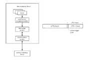
- FIG. 1which includes a data acquisition device and a motion computing device, as introduced above.
- the data acquisition devicemainly comprises a sensor and a communications module.
- the motion data collected at the sensoris transmitted in real time to the motion computing device via the communications module.
- the sensor mentioned hereinincludes, but is not limited to, an acceleration sensor, gyroscope, and a magnetic field sensor, etc.
- the data acquisition device and the motion computing devicegenerally communicate motion data in real time over a wireless channel, and the motion computing device uses acceleration-based integral algorithms to compute the motion. Consequently, when subjected to the same amount of noises, the higher the sampling rate, the more accurate the computed position and posture data. Nonetheless, in the case of a high sampling rate, the huge amount of data collected by the sensor will exert too much pressure on the transmission over the wireless channel. This not only results in large wireless power consumption, but also goes beyond the maximum capacity of the wireless channel.
- the present inventionprovides a data acquisition method and device for motion recognition, a motion recognition system and a computer readable storage medium, which provides high accuracy in motion recognition and reduces wireless power consumption under the same sampling rate.
- the present inventiondiscloses:
- a data acquisition method for motion recognitionfor use in a data acquisition device comprising an initial motion recognition module, a data storage module and a communications module, the method comprising: Step S1) the initial motion recognition module performing an initial recognition with respect to motion data acquired by a sensor, and providing motion data describing a predefined range around a motion trigger point to the data storage module for storage; and Step S2) the communications module forwarding the motion data stored at the data storage module to a motion computing device for motion recognition;
- a data acquisition device for motion recognitioncomprising: an initial motion recognition module adapted to perform an initial recognition with respect to motion data collected by a sensor and provide motion data describing a predefined range around a motion trigger point to a data storage module for storage; a data storage module adapted to store motion data provided from the initial motion recognition module; and a communications module adapted to transmit the motion data stored in the data storage module to a motion computing device for motion recognition;
- a motion recognition systemcomprising: a motion computing device; and the aforesaid data acquisition device, wherein the motion computing device is adapted to perform motion recognition based on motion data transmitted from the data acquisition device; and
- a computer readable storage mediumwhich stores programs for executing the aforesaid data acquisition method for motion recognition.
- the data acquisition device of the present disclosureis provided with an initial motion recognition module and a data storage module.
- the initial motion recognition moduleperforms an initial recognition on the motion data collected by the sensor, and the data storage module only maintains the part of data describing a predefined range around a motion trigger point, which is of significance to the motion recognition, and transmits this part of data to the motion computing device.
- an initial selectionis made to the motion data to be transmitted to the motion computing device under the same sampling rate. Consequently, the present invention reduces pressures on the wireless channel transmission and power consumption, and provides high accuracy in motion recognition while providing motion data at the same sampling rate.
- FIG. 1illustrates a conventional motion recognition system.
- FIG. 2illustrates a system according to a first embodiment of the present disclosure.
- FIG. 3illustrates a set of motion data stored in the data storage module included in the system according to the first embodiment of the present disclosure.
- FIG. 4 aillustrates a data frame format according to a first embodiment of the present disclosure.
- FIG. 4 billustrates another data frame format according to a first embodiment of the present disclosure.
- FIG. 5shows a flow diagram of motion detection performed by an initial motion recognition module according to a second embodiment of the present disclosure.
- FIG. 6shows a motion recognition module according to a third embodiment of the present disclosure.
- the significance of the present inventionresides in introducing an initial motion recognition module and a data storage module into a data acquisition device.
- the data acquisition deviceis capable of initial selection and buffer of the motion data, excluding data which describes a static status and is insignificant to the motion recognition.
- the data acquisition devicetransports the buffered motion data voluntarily or in response to a request to a motion computing device for particular motion recognition.
- the present inventionis introduced in details by way of particular embodiments.
- FIG. 2illustrates a system in accordance with a first embodiment of the present invention.
- the systemalso comprises a data acquisition device and a motion computing device.
- the present systemincludes not only a sensor and a communications module within the data acquisition device, but also an initial motion recognition module and a data storage module. The connections therebetween are as shown in FIG. 2 .
- the data acquisition devicemay be configured in, but not limited to, a recognizable object such as a club, a bat and glove to collect motion data related to the object to be recognized.
- the motion computing devicemay be disposed on, but is not limited to, an intelligent terminal such as a mobile phone, a tablet computer, and PDA.
- the data acquisition device and the motion computing devicecommunicate data via a wireless channel, for example, WIFI, NFC (Near Field Communications), Infrared, and Bluetooth, etc. Of course, they may also communicate data via a wired network.
- the sensor included in the data acquisition deviceis adapted to collect motion data related to the object to be recognized.
- the motion datamay include data describing the object being static, and data describing the object in movement.
- the sensormay be implemented as, but is not limited to, an acceleration sensor, a gyroscope, a magnetic field sensor, and a compass, etc.
- the sensormay be a group of sensors consisting of a three-axis acceleration sensor, a three-axis gyroscope, and a three-axis magnetic field sensor.
- the motion datamay comprise acceleration, an angular speed and an attitude angle relative to a three-dimensional geomagnetic coordinate system of the object to be recognized.
- the initial motion recognition moduleis configured to perform an initial recognition with respect to the motion data collected by the sensor, and provide the motion data describing a predefined range around a motion trigger point to the data storage module, which then stores the motion data transmitted from the initial motion recognition module.
- the main purpose of the initial recognition conducted by the initial motion recognition moduleis to detect motion, to be more specific, to initially detect a motion trigger point.
- the initial motion recognition module within the data acquisition deviceis not required to perform accurate initial motion recognition, but instead rough initial motion recognition.
- the initial motion recognition moduleis required to provide not only the motion data after the motion trigger point (including the motion trigger point per se) to the data storage module, but also the data before the motion trigger point.
- the initial motion recognition moduleneeds to provide m*Fs frames of motion data before the motion trigger point, the motion data regarding the motion trigger point per se, and n*Fs ⁇ 1 frames of motion data after the motion trigger point, wherein m and n are a predefined positive integer, and Fs is a sampling rate. These frames of data constitute one set of motion data.
- m and nare a predefined positive integer, and Fs is a sampling rate.
- One frame of motion datarefers to a collection of sampling data collected by various sensors within the same sampling moment.
- said “one frame of motion data”will include ⁇ Acc X, Acc Y, Acc Z; Gyro X, Gyro Y, Gyro Z; and Mag X, Mag Y, Mag Z ⁇ , wherein Acc X, Acc Y, Acc Z respectively represent the accelerations along Axis X, Y and Z collected by the three-axis acceleration sensor; Gyro X, Gyro Y, Gyro Z respectively represent the angular speeds rotated around Axis X, Y and Z collected by the gyroscope; and Mag X, Mag Y, and Mag Z respectively represent the magnetic field strengths along Axis X, Y and Z collected by the three-axis magnetic field sensor.
- the frame format of the stored datamay be as shown in FIG. 4 , wherein LSB is the least significant bit, and MSB is the most significant bit.
- Another examplemay comprise a three-axis acceleration sensor, a three-axis gyroscope, a high G acceleration sensor and a three-axis magnetic field sensor.
- the one frame of motion datawill be ⁇ Acc X, Acc Y, Acc Z; Gyro X, Gyro Y, Gyro Z; Acc high X, Acc high Y, Acc high Z; Mag X, Mag Y, Mag Z ⁇ .
- Acc X, Acc Y, Acc Zrespectively represent the accelerations along Axis X, Y and Z collected by the three-axis acceleration sensor
- Gyro X, Gyro Y, Gyro Zrespectively represent the angular speeds rotated around Axis X, Y and Z collected by the gyroscope
- Acc high X, Acc high Y, Acc high Zrespectively represent the accelerations along Axis X, Y and Z collected by the high G acceleration sensor
- Mag X, Mag Y, and Mag Zrespectively represent the magnetic field strengths along Axis X, Y and Z collected by the three-axis magnetic field sensor.
- the frame format of the stored datamay be as shown in FIG. 4 b.
- the communications moduleis adapted to transmit the motion data stored in the data storage module to the motion computing device.
- the transmission of motion datais mainly completed in two manners: one is to transmit data voluntarily; and the other one is to transmit data in response to request.
- the aforesaid voluntary data transmissionmay include, but is not limited to, the following: 1) after one set of motion data is initially recognized and stored, the stored motion data is voluntarily transmitted to the motion computing device; 2) the motion data stored within the current period is voluntarily transmitted to the motion computing device periodically; and 3) the user initiates the transmission of the stored motion data to the motion computing device, for example, the user triggers the data acquisition device to transport the latest N1 set of motion data, wherein N1 is a preset positive integer.
- the motion computing deviceIn the case of data transmission in response to request, the motion computing device needs to send a request for collecting data to the data acquisition device.
- the communications module of the data acquisition devicetransmits the requested motion data stored in the data storage module to the motion computing device.
- the motion computing devicemay request a certain range of motion data from the data acquisition device, for example, the latest N1 set of motion data, the oldest N2 set of motion data, etc, wherein N2 is a preset positive integer.
- the motion computing devicemay request all of the motion data that the data acquisition device has not yet shared therewith.
- the motion computing deviceis capable of motion recognition by analyzing and computing the motion data transmitted from the data acquisition device.
- Embodiment 2will be set forth below to explain in detail the motion detection by the initial motion recognition module.
- the motion detection conducted by the initial motion recognition moduleinvolves the detection of a motion trigger point, and requires to transmit the m*Fs frames of data preceding the motion trigger point and the n*Fs frames of data after the motion trigger point (including the motion trigger point per se) to the data storage module for storage. Consequently, in this embodiment, a first buffer and a second buffer are employed to respectively store data frames preceding the detection of the motion trigger point, and data frames after the detection of the motion trigger point.
- the first bufferis sized to store m*Fs frames.
- the first bufferhas a fixed size such that when the first buffer is full, the extra data frames that are continued to be written in will overwrite the oldest data frames. This design makes sure that once the motion trigger point is located, the first buffer will exactly store m*Fs frames of data. To increase operation efficiency, a circulating queue is designed in the first buffer, which maintains a write pointer always pointing to the address of the next write operation. Therefore, when the write pointer points to the last address of the buffer, the next write triggers the write pointer to point to the first address of the buffer.
- the second buffer used in this embodimentmay simply be designed to use a sequential storage.
- the aforesaid data storageis mainly implemented as follows: the initial motion recognition module buffers the motion data transmitted from the sensor and conducts a motion trigger point detection.
- the m*Fs frames of data preceding the motion trigger pointare stored in the first buffer, while the data frames starting from the motion trigger point are placed into the second buffer.
- the second buffermaintains up to n*Fs frames of data
- the entire set of motion data consisting of the m*Fs frames in the first buffer and the n*Fs frames in the second bufferis transmitted to and stored in the data storage module. Described below is a preferred embodiment for the aforesaid motion detection approach.
- FIG. 5shows a flow diagram of motion detection performed by an initial motion recognition module according to a second embodiment of the present disclosure.
- the motion detectioncomprises the following steps:
- a frame of motion datais acquired from a sensor.
- Step 502it is determined whether a motion trigger point status is idle. If no, the process skips to Step 504 ; if yes, the process proceeds to Step 503 .
- Step 502is intended to determine whether a motion trigger point occurs by determining whether the motion trigger point status is idle.
- the motion trigger point statusis initially set to “Idle”. Once the motion trigger point is detected, it is changed to “Non-idle”. After completing the acquisition of one set of motion data, the status returns to “Idle”.
- Step 503tries to detect the motion trigger point based on the acquired motion data. If the motion trigger point fails to be detected, the currently acquired motion data is placed into the first buffer, and then the process returns to Step 501 to acquire the next frame of motion data. If the motion trigger point is detected, the process proceeds to Step 504 .
- the motion trigger pointfails to be detected at Step 503 , it is necessary to detect the motion trigger point with respect to each frame of motion data until the motion trigger point is eventually detected.
- the motion trigger point detection in this stepcomprises detection of stroke and a large-dimension motion. If a stroke or a large-dimension motion is detected, the motion trigger point is deemed to have been detected, and the motion trigger point status is set to “Non-idle”. On the contrary, no motion trigger point is deemed to have been detected.
- the occurrence of strokeis judged by determining whether a sudden change occurs to the acceleration or the angular speed at a certain point.
- the strokemay be detected using the following three methods.
- the first methodis to detect the stroke solely based on whether a sudden change occurs to the acceleration. In particular, it is determined whether the difference between the acceleration of the current frame of motion data and the acceleration of the last frame of motion data reaches a threshold value predefined for the sudden change in the acceleration. If the result is positive, a stroke is deemed to have occurred.
- the accelerationmay be three-dimensional data obtained via a three-axis acceleration sensor
- the aforesaid difference values to be determinedmay comprise the difference in ACC X between the current frame and the last frame, the difference in ACC Y between the current frame and the last frame, and the difference in ACC Z between the current frame and the last frame.
- the second methodis to determine a stroke solely based on whether a sudden change occurs to the angular speed. In particular, it is determined whether the difference between the angular speed of the current frame of motion data and the angular speed of the last frame of motion data reaches a threshold value predefined for the sudden change in the angular speed. If the result is positive, a stroke is deemed to have occurred.
- the aforesaid difference values to be determinedcomprise the difference in Gyro X between the current frame and the last frame, the difference in Gyro Y between the current frame and the last frame, and the difference in Gyro Z between the current frame and the last frame. If an M2 number of these difference values reach up to the threshold value predefined for the sudden change in the angular speed, a determination is made that the difference between the angular speed of the current frame of motion data and the angular speed of the last frame of motion data reaches the threshold value predefined for the sudden change in the angular speed. Said “M2” is set to one, two or three.
- the third methodis to determine a stroke based on whether a sudden change occurs to both the acceleration and the angular speed. In particular, it is determined whether the difference between the acceleration of the current frame of motion data and the acceleration of the last frame of motion data reaches a threshold value predefined for the sudden change in the acceleration, and meanwhile whether the difference between the angular speed of the current frame of motion data and the angular speed of the last frame of motion data reaches a threshold value predefined for the sudden change in the angular speed. If both results are found to be true, a stroke is deemed to have occurred.
- the determination with respect to the accelerationis the same as discussed above in the first method, and the determination with respect to the angular speed is the same as discussed above in the second method.
- the third oneis preferred in that it is reliable in recognition and reduces error rate.
- the selection of M1 and M2is, to some extent, dependent on the position of the data acquisition device. For example, if the data acquisition device is disposed on a glove, M1 and M2 may be set to a relatively large value, for example, two or three. If it is disposed on a club, which is more sensitive to the motion, M1 and M2 may be set to a smaller value, for example, one or two.
- the selection of M1 and D2is also related to the particular types of sports to some extent.
- a strokeoccurs when the golf club hits the golf ball.
- the impacti.e., the moment when the golf club hits the golf ball, is the motion trigger point in the sense of the present disclosure.
- the data acquisition device disposed on the golf club or gloveacquires the current frame of motion data via a sensor.
- the large-dimension motion detectionfollows the principle that a large-dimension motion is deemed to have occurred if the acceleration of the current frame of motion data is large enough to reach a predefined threshold, and meanwhile the angular speed is also large enough to reach a predefined threshold.
- the acceleration and the angular speedsare usually determined by computing Mod of the three-axis acceleration vector and the three-axis angular speed. For example, if the acceleration is 6 times or more as large as the gravitational acceleration and meanwhile the angular speed is larger than 800 rad/s, a large-dimension motion is determined positive.
- Step 504the currently acquired frame of motion data is stored in a second buffer, and the motion trigger point status is set to “Non-idle”.
- the subsequent frames of data starting from said current frameneed to be placed into the second buffer.
- Step 505It is then determined at Step 505 whether the number of frames stored in the second buffer reaches n*Fs. If it is negative, the process returns to Step 501 to acquire the next frame of motion data. If it is positive, the process proceeds to Step 506 .
- the motion data stored in the first buffer and the motion data stored in the second buffer, as a single set of motion data,are provided to and stored in the data storage module.
- the motion data in the second bufferis then forwarded to the data storage module, such that the data storage module may store the acquired one set of motion data in a format as shown in FIG. 3 .
- the motion trigger point statusis set to “Idle” at Step 507 to terminate the acquisition of the current set of motion data.
- the first and second buffersare cleared, and the motion trigger point status is initialized to start the process again from Step 501 .
- the core of the data acquisition device provided in the present inventionconsists in the initial motion recognition module.
- the structure of this initial motion recognition moduleis illustrated in detail by way of Embodiment 3.
- FIG. 6shows a motion recognition module according to a third embodiment of the present disclosure.
- the motion recognition modulemainly comprises a buffer and detection module 00 and a storage interactive module 10 .
- the buffer and detection module 00comprises: a data acquisition module 01 , a first determination module 02 , a motion detection module 03 , a data buffering module 04 and a second determination module 05 .
- the buffer and detection module 00buffers the motion data collected by the sensor and detects a motion trigger point.
- m*Fs frames of motion data prior to the motion trigger pointare placed into the first buffer
- frames of motion data after the motion trigger pointare placed into the second buffer.
- the first bufferhas a fixed size such that when the first buffer is full, the extra data frames that are continued to be written in will overwrite the oldest data frames.
- the second buffer used in this embodimentmay simply be designed to use a sequential storage.
- the storage interactive module 10forwards the complete set of motion data consisting of the m*Fs frames in the first buffer and the n*Fs frames in the second buffer to the data storage module for storage.
- the buffer and detection module 00is set forth in greater details below.
- the data acquisition module 01is adapted to acquire a frame of motion data from the sensor. Put it another way, the data acquisition module 01 receives, frame by frame, the motion data which the sensor collects at various sampling moments, and triggers the first determination module 01 to start operation.
- the first determination module 02determines whether the motion trigger point status is idle. If it is not idle, the first determination module 02 then triggers the data buffering module 04 . If it is idle, the first determination module 02 then triggers the motion detection module 03 .
- the motion trigger point in this embodimentis intended to identify whether a motion trigger point is detected in the current set of motion data. The initial status of the motion trigger point is set to “Idle”, which means that no motion trigger point is detected. Once the motion trigger point is located, the motion trigger point status is set to “Non-idle”, and reset to “Idle” after one set of motion data has been acquired.
- the motion detection module 03detects the motion trigger point based on the current frame of motion data. If the motion detection module 03 does not detect a motion trigger point, it triggers the data buffering module 04 . If the motion detection module 03 detects a motion trigger point, it sets the motion trigger point status to “Non-idle”.
- the motion trigger point detection by the motion detection module 03 during the initial motion recognitioncomprises at least one of a stroke detection and a large-dimension motion detection. If the motion detection module 03 detects a stroke or a large-dimension motion, the motion trigger point is deemed to have been detected; otherwise, no motion trigger point is deemed to have been detected.
- the strokemay be detected by determining one of the following:
- M1may be set to one, two or three, and Acc X, Acc Y and Acc Z respectively represent the accelerations along X-, Y- and Z-axis collected by the three-axis acceleration sensor.
- a three-axis angular speed sensoris used to collect the angular speed, the differences in Gyro X, Gyro Y and Gyro Z between the current and the last frames of motion data are respectively determined. If a M2 number of difference values reaches up to the predefined threshold value for the sudden change in the angular speed, it is determined that the difference between the angular speed of the current frame of motion data and the angular speed of the last frame of motion data reaches a threshold value predefined for the sudden change in the angular speed. M2 may be set to one, two or three, and Gyro X, Gyro Y and Gyro Z respectively represent the angular speed around X-, Y- and Z-axis collected by the three-axis angular speed sensor.
- the aforesaid third methodis the most preferred, because this method is more reliable in motion recognition and has a reduced error rate.
- the selection of M1 and M2is, to some extent, dependent on the position of the data acquisition device. For example, if the data acquisition device is disposed on a glove, M1 and M2 may be set to a relatively large value, for example, two or three. If the data acquisition device is disposed on a club, which is more sensitive to motion, M1 and M2 may be set to a smaller value, for example, one or two. Besides, the selection of M1 and M2 is also dependent on the particular types of sports to some extent.
- the large-dimension motionmay be detected by determining whether the acceleration of the currently acquired frame of motion data is large enough to reach a predefined acceleration threshold, and meanwhile the angular speed is also large enough to reach a predefined angular speed threshold. If both results are positive, it is determined that a large-dimension motion has occurred.
- the acceleration and the angular speedare usually determined by computing Mod of the three-axis acceleration vector and the three-axis angular speed. For example, if the acceleration is 6 times or more as large as the gravitational acceleration and meanwhile the angular speed is larger than 800 rad/s, a large-dimension motion is determined positive.
- the data buffering module 04When triggered by the motion detection module 03 , the data buffering module 04 stores the currently obtained frame of motion data into a first buffer, whereas when triggered by the first determination module 02 , the data buffering module 04 places the currently obtained frame of motion data into a second buffer and triggers the second determination module 05 .
- the second determination module 05determines whether the number of frames stored in the second buffer reaches up to n*Fs. If the number of frames stored in the second buffer reaches up to n*Fs, the storage interactive module 10 will forward the complete set of motion data consisting of the m*Fs frames in the first buffer and the n*Fs frames in the second buffer to the data storage module for storage. Upon completion of operation, the storage interactive module 10 initializes the motion trigger point status to “Idle”.
- the motion computing deviceGiven the motion data from the data acquisition device, will be able to perform motion recognition with respect to ball games such as, golf and badminton.
- the motion recognitionmay include, but is not limited to: 1) acquiring and storing one set of motion data by the motion computing device, i.e., receiving motion data from the data acquisition device.
- the sensor disposed in the data acquisition devicemay comprise a three-axis acceleration sensor, a three-axis gyroscope, and a three-axis magnetic field sensor, and the motion data to be collected may comprise acceleration, angular speed, and attitude angle relative to a three-dimensional geomagnetic coordinate system.
- Feature point 1at Feature point 1, the speed is zero. It corresponds to static alignment at an initial time moment.
- Feature point 2this point is identified if the ratios of the speed at the horizontal dimension to the speeds at the other two dimensions both exceed a predefined ratio specific for Feature point 2. This point corresponds to takeaway of the backswing where the arm is almost horizontal.
- Feature point 3this point is identified if the ratios of the speed in a first direction at the vertical dimension to the speeds at the other two dimensions both exceed a predefined ratio specific for Feature point 3. This point corresponds to the halfway of the backswing where the club is swung to a direction almost vertical to the ground.
- Feature point 4this point is identified if the speed at the vertical dimension is smaller than a predefined threshold specific for Feature point 4, and, more preferably, meanwhile highness and acceleration both meet the requirements predefined for Feature point 4. This point corresponds to the top of the backswing where the speed at the vertical dimension is almost zero, and where highness and posture of the arm are both limited.
- Feature point 5this point is identified if the ratios of the speed in a second direction at the vertical dimension to the speeds at the other two dimensions both exceed a predefined ratio specific for Feature point 5.
- the second directionis opposite to the aforesaid first direction, and the ratios at Feature point 5 are larger than those at Feature point 3.
- This pointcorresponds to downswing to get ready for the stroke, which is similar to the halfway of backswing, but has a larger speed and an opposite direction.
- Feature point 6this point needs to be explained in two different situations. In the first situation, the golfer simply practices golf swing without hitting the golf ball; while in the second situation, the golfer hits the golf ball with the golf club. At the impact, the golf club hits the ball at a very high speed to cause a severe change to the acceleration.
- Feature point 6is identified if min( ⁇ X t ⁇ X init ⁇ + ⁇ T t ⁇ T init ⁇ ) at the sampling moment t is smaller than a preset threshold value specific for Feature point 6.
- X trepresents the position at the sampling moment t
- X initrepresents the position at the initial moment t 0
- T trepresents the posture at the sampling moment t
- T initrepresents the posture at the initial moment t 0 .
- ⁇ and ⁇are preset parameters, and T init and T t particularly represent the rotated posture of the object to be identified at the sampling moments t 0 and t respectively.
- Feature point 6is identified if a change rate of the acceleration at a certain moment exceeds a predefined threshold for the change rate of the acceleration specific for Feature point 6. This point corresponds to the stroke. More preferably, for golf swing, an obvious fluctuation will occur to the change rate of the angular speed at the impact. Therefore, it can be determined that there is a moment when the change rate of the acceleration exceeds a threshold change rate for the angular speed specifically preset for Feature point 6.
- the motion types corresponding to the provided sets of motion dataare eventually recognized, stored, outputted or displayed. Also stored, outputted or displayed include such motion parameters as the acceleration, speed, position and posture at various sampling moments.
- the motion recognition method used by the motion recognition device presented in the present inventionis nothing but one of the methods as listed. The present disclosure is not limited to any recognition methods used by the motion recognition devices, and is not intended to list exhaustively all of the recognition methods. It would be also appreciated that the aforesaid particular recognition methods may be performed off-line.
- the aforesaid integrated modules which are implemented as functional software modulesmay be maintained in a computer readable storage medium, which comprises instructions that enable a computer device (e.g., a PC, server or a network device, etc) or a processor to execute part of the steps included in the methods throughout the embodiments of the present invention.
- This computer readable storage mediummay comprise various mediums which can store program codes such as a U-disk, a mobile hard disk, Read-only Memory (ROM), a Random Access Memory (RAM), a diskette or disk.
Landscapes
- Engineering & Computer Science (AREA)
- Theoretical Computer Science (AREA)
- Physics & Mathematics (AREA)
- General Physics & Mathematics (AREA)
- General Engineering & Computer Science (AREA)
- Multimedia (AREA)
- Human Computer Interaction (AREA)
- Computer Vision & Pattern Recognition (AREA)
- Software Systems (AREA)
- Measurement Of The Respiration, Hearing Ability, Form, And Blood Characteristics Of Living Organisms (AREA)
- User Interface Of Digital Computer (AREA)
Abstract
Description
Claims (18)
Applications Claiming Priority (3)
| Application Number | Priority Date | Filing Date | Title |
|---|---|---|---|
| CN201310049750 | 2013-02-07 | ||
| CN201310049750.3 | 2013-02-07 | ||
| CN201310049750.3ACN103076884B (en) | 2013-02-07 | 2013-02-07 | Data acquisition method and data acquisition device for motion recognition, and motion recognition system |
Publications (2)
| Publication Number | Publication Date |
|---|---|
| US20140219498A1 US20140219498A1 (en) | 2014-08-07 |
| US8989441B2true US8989441B2 (en) | 2015-03-24 |
Family
ID=48153442
Family Applications (1)
| Application Number | Title | Priority Date | Filing Date |
|---|---|---|---|
| US13/846,700Active2033-08-17US8989441B2 (en) | 2013-02-07 | 2013-03-18 | Data acquisition method and device for motion recognition, motion recognition system and computer readable storage medium |
Country Status (3)
| Country | Link |
|---|---|
| US (1) | US8989441B2 (en) |
| CN (1) | CN103076884B (en) |
| WO (1) | WO2014121566A1 (en) |
Cited By (56)
| Publication number | Priority date | Publication date | Assignee | Title |
|---|---|---|---|---|
| CN105046730A (en)* | 2015-07-09 | 2015-11-11 | 北京盛世宣合信息科技有限公司 | Writing trace demonstration method and apparatus applied to writing brush |
| US9235765B2 (en) | 2010-08-26 | 2016-01-12 | Blast Motion Inc. | Video and motion event integration system |
| US9247212B2 (en) | 2010-08-26 | 2016-01-26 | Blast Motion Inc. | Intelligent motion capture element |
| US9261526B2 (en) | 2010-08-26 | 2016-02-16 | Blast Motion Inc. | Fitting system for sporting equipment |
| US9283457B2 (en) | 2012-11-09 | 2016-03-15 | Wilson Sporting Goods Co. | Sport performance system with ball sensing |
| US9320957B2 (en) | 2010-08-26 | 2016-04-26 | Blast Motion Inc. | Wireless and visual hybrid motion capture system |
| US9349049B2 (en) | 2010-08-26 | 2016-05-24 | Blast Motion Inc. | Motion capture and analysis system |
| WO2016081778A1 (en)* | 2014-11-20 | 2016-05-26 | Blast Motion Inc. | Video and motion event integration system |
| US9361522B2 (en) | 2010-08-26 | 2016-06-07 | Blast Motion Inc. | Motion event recognition and video synchronization system and method |
| US9396385B2 (en) | 2010-08-26 | 2016-07-19 | Blast Motion Inc. | Integrated sensor and video motion analysis method |
| US9401178B2 (en) | 2010-08-26 | 2016-07-26 | Blast Motion Inc. | Event analysis system |
| US9406336B2 (en) | 2010-08-26 | 2016-08-02 | Blast Motion Inc. | Multi-sensor event detection system |
| US9418705B2 (en) | 2010-08-26 | 2016-08-16 | Blast Motion Inc. | Sensor and media event detection system |
| US9607652B2 (en) | 2010-08-26 | 2017-03-28 | Blast Motion Inc. | Multi-sensor event detection and tagging system |
| US9604142B2 (en) | 2010-08-26 | 2017-03-28 | Blast Motion Inc. | Portable wireless mobile device motion capture data mining system and method |
| US9619891B2 (en) | 2010-08-26 | 2017-04-11 | Blast Motion Inc. | Event analysis and tagging system |
| US9626554B2 (en) | 2010-08-26 | 2017-04-18 | Blast Motion Inc. | Motion capture system that combines sensors with different measurement ranges |
| US9623311B2 (en) | 2012-11-09 | 2017-04-18 | Wilson Sporting Goods Co. | Basketball sensing apparatus |
| US9636550B2 (en) | 2009-11-19 | 2017-05-02 | Wilson Sporting Goods Co. | Football sensing |
| US9646209B2 (en) | 2010-08-26 | 2017-05-09 | Blast Motion Inc. | Sensor and media event detection and tagging system |
| US9656143B2 (en) | 2012-11-09 | 2017-05-23 | Wilson Sporting Goods Co. | Basketball shot determination system |
| US9656140B2 (en) | 2012-11-09 | 2017-05-23 | Wilson Sporting Goods Co. | Sport performance system with ball sensing |
| US9656142B2 (en) | 2012-11-09 | 2017-05-23 | Wilson Sporting Goods Co. | Basketball shot determination system |
| US9694267B1 (en) | 2016-07-19 | 2017-07-04 | Blast Motion Inc. | Swing analysis method using a swing plane reference frame |
| US9833683B2 (en) | 2013-10-16 | 2017-12-05 | Wilson Sporting Goods Co. | Golf ball and caddie system |
| US9844704B2 (en) | 2012-11-09 | 2017-12-19 | Wilson Sporting Goods Co. | Basketball sensing apparatus |
| US9901801B2 (en) | 2012-11-09 | 2018-02-27 | Wilson Sporting Goods Co. | Basketball sensing apparatus |
| US9916001B2 (en) | 2014-07-08 | 2018-03-13 | Wilson Sporting Goods Co. | Sport equipment input mode control |
| US9940508B2 (en) | 2010-08-26 | 2018-04-10 | Blast Motion Inc. | Event detection, confirmation and publication system that integrates sensor data and social media |
| US10019630B1 (en)* | 2017-01-09 | 2018-07-10 | Sap Se | Dynamic classification system for sports analysis |
| US10080941B2 (en) | 2015-07-02 | 2018-09-25 | Sumitomo Rubber Industries, Ltd. | Method, system, and apparatus for analyzing a sporting apparatus |
| US10124230B2 (en) | 2016-07-19 | 2018-11-13 | Blast Motion Inc. | Swing analysis method using a sweet spot trajectory |
| US10159884B2 (en) | 2012-11-09 | 2018-12-25 | Wilson Sporting Goods Co. | Basketball make-miss shot sensing |
| US10215542B2 (en) | 2015-12-09 | 2019-02-26 | Virtual Clays, LLC | System for analyzing performance of an activity involving using an implement to strike a moving target object effectively |
| US10220286B2 (en) | 2013-10-16 | 2019-03-05 | Wilson Sporting Goods Co. | Golf ball and caddie system |
| US10232225B1 (en) | 2015-06-01 | 2019-03-19 | Mitchell O Enterprises LLC | Systems and methods for obtaining sports-related data |
| US10265602B2 (en) | 2016-03-03 | 2019-04-23 | Blast Motion Inc. | Aiming feedback system with inertial sensors |
| US10427017B2 (en) | 2014-05-20 | 2019-10-01 | Arccos Golf Llc | System and method for monitoring performance characteristics associated with user activities involving swinging instruments |
| US10478689B2 (en) | 2015-07-02 | 2019-11-19 | Sumitomo Rubber Industries, Ltd. | Method, system, and apparatus for analyzing a sporting apparatus |
| US10565888B2 (en) | 2013-02-17 | 2020-02-18 | Ronald Charles Krosky | Instruction production |
| US10589161B2 (en) | 2015-07-21 | 2020-03-17 | Arccos Golf, Llc | System and method for monitoring performance characteristics associated with user activities involving swinging instruments |
| US10610732B2 (en) | 2011-08-29 | 2020-04-07 | Icuemotion Llc | Inertial sensor motion tracking and stroke analysis system |
| US10668333B2 (en) | 2009-11-19 | 2020-06-02 | Wilson Sporting Goods Co. | Football sensing |
| US10668353B2 (en) | 2014-08-11 | 2020-06-02 | Icuemotion Llc | Codification and cueing system for sport and vocational activities |
| US10682562B2 (en) | 2017-01-17 | 2020-06-16 | Arccos Golf Llc | Autonomous personalized golf recommendation and analysis environment |
| US10716971B1 (en) | 2015-06-01 | 2020-07-21 | Mitchell O Enterprises LLC | Game implements and system for tracking or locating same |
| US10751579B2 (en) | 2009-11-19 | 2020-08-25 | Wilson Sporting Goods Co. | Football sensing |
| US10786728B2 (en) | 2017-05-23 | 2020-09-29 | Blast Motion Inc. | Motion mirroring system that incorporates virtual environment constraints |
| US10821329B2 (en) | 2009-11-19 | 2020-11-03 | Wilson Sporting Goods Co. | Football sensing |
| US10854104B2 (en) | 2015-08-28 | 2020-12-01 | Icuemotion Llc | System for movement skill analysis and skill augmentation and cueing |
| US11565163B2 (en) | 2015-07-16 | 2023-01-31 | Blast Motion Inc. | Equipment fitting system that compares swing metrics |
| US11577142B2 (en) | 2015-07-16 | 2023-02-14 | Blast Motion Inc. | Swing analysis system that calculates a rotational profile |
| US11779822B2 (en) | 2021-08-31 | 2023-10-10 | Icecap Sports Club | Motion analyzer for sports equipment |
| US11833406B2 (en) | 2015-07-16 | 2023-12-05 | Blast Motion Inc. | Swing quality measurement system |
| US11990160B2 (en) | 2015-07-16 | 2024-05-21 | Blast Motion Inc. | Disparate sensor event correlation system |
| US12172066B2 (en) | 2017-01-17 | 2024-12-24 | Arccos Golf Llc | Autonomous tracking and personalized golf recommendation and analysis environment |
Families Citing this family (27)
| Publication number | Priority date | Publication date | Assignee | Title |
|---|---|---|---|---|
| CN103076884B (en)* | 2013-02-07 | 2015-03-25 | 泽普互动(天津)科技有限公司 | Data acquisition method and data acquisition device for motion recognition, and motion recognition system |
| US20150032237A1 (en)* | 2013-07-25 | 2015-01-29 | Active Network, Llc | Automated golf scoring |
| CN104463087A (en)* | 2013-11-25 | 2015-03-25 | 安徽寰智信息科技股份有限公司 | Action identification device and method |
| US10362263B2 (en) | 2014-07-02 | 2019-07-23 | Amer Sports Digital Services Oy | System and method for remote activation of a storage operation of pictorial information |
| WO2019122535A1 (en)* | 2017-12-22 | 2019-06-27 | Suunto Oy | A system and method for remote activation of a storage operation of pictorial information |
| CN105771219A (en)* | 2014-12-24 | 2016-07-20 | 北京中体动力数字技术有限公司 | Stroke frequency acquisition device and acquisition method thereof |
| CN105302289B (en)* | 2015-03-26 | 2018-04-20 | 赵蕴龙 | Fixation stroke capitalization English letter automatic identifying method based on mobile phone |
| CN104933423A (en)* | 2015-07-08 | 2015-09-23 | 安徽瑞宏信息科技有限公司 | Motion identification apparatus and method |
| CN104978032B (en)* | 2015-07-08 | 2018-06-29 | 苏州奥莱维信息技术有限公司 | A kind of multimedia control device based on gesture identification |
| US20170076618A1 (en)* | 2015-09-14 | 2017-03-16 | Adobe Systems Incorporated | Physical Object Training Feedback Based On Object-Collected Usage Data |
| CN105898059A (en)* | 2016-04-20 | 2016-08-24 | 北京动量科技有限责任公司 | Method and apparatus for acquiring attitude result information |
| CN106197473A (en)* | 2016-06-24 | 2016-12-07 | 北京奇虎科技有限公司 | The crawler behavior recognition methods of equipment and device |
| CN106097843A (en)* | 2016-08-30 | 2016-11-09 | 广东工业大学 | A kind of kinesiology experimental system and method |
| CN106778477B (en)* | 2016-11-21 | 2020-04-03 | 深圳市酷浪云计算有限公司 | Tennis racket action recognition method and device |
| CN106650659B (en)* | 2016-12-19 | 2020-06-19 | 深圳市酷浪云计算有限公司 | Method and device for identifying motion parameters of bat |
| CN106669114A (en)* | 2017-01-10 | 2017-05-17 | 悦物电子科技(上海)有限公司 | Method and device for obtaining impact point spatio-temporal information |
| CN107883953B (en)* | 2017-09-26 | 2021-05-25 | 广州新维感信息技术有限公司 | VR handle static detection algorithm, VR handle and storage medium |
| CN107920203A (en)* | 2017-11-23 | 2018-04-17 | 乐蜜有限公司 | Image-pickup method, device and electronic equipment |
| CN109510551A (en)* | 2018-12-28 | 2019-03-22 | 上海辛格林纳新时达电机有限公司 | The implementation method and device of essential safe type servo-system |
| CN110052000A (en)* | 2019-04-12 | 2019-07-26 | 漳州泰里斯体育器材有限公司 | A kind of identifying processing method and system of combat sports state |
| CN111310599B (en)* | 2020-01-20 | 2021-08-03 | 重庆大学 | A sleep action recognition system that can quickly adapt to various changing factors |
| CN112346580B (en)* | 2020-10-27 | 2024-01-12 | 努比亚技术有限公司 | Motion gesture detection method, device and computer readable storage medium |
| CN113188645B (en)* | 2021-04-29 | 2024-07-23 | 深圳市工匠社科技有限公司 | Hit recognition method, device, equipment, storage medium and competition equipment |
| CN113283493B (en)* | 2021-05-19 | 2024-11-29 | Oppo广东移动通信有限公司 | Sample acquisition method, device, terminal and storage medium |
| CN113313007B (en)* | 2021-05-26 | 2022-10-14 | 每日互动股份有限公司 | Pedestrian static state identification method based on video, electronic equipment and storage medium |
| CN113269318B (en)* | 2021-06-04 | 2023-06-30 | 安谋科技(中国)有限公司 | Electronic equipment, neural network model operation method thereof and storage medium |
| CN114011042A (en)* | 2021-10-19 | 2022-02-08 | 江苏泰扬金属制品有限公司 | Cloud service type target replacement platform |
Citations (5)
| Publication number | Priority date | Publication date | Assignee | Title |
|---|---|---|---|---|
| US6289124B1 (en)* | 1998-04-27 | 2001-09-11 | Sanyo Electric Co., Ltd. | Method and system of handwritten-character recognition |
| US20050259739A1 (en)* | 2004-04-09 | 2005-11-24 | Sony Corporation | Image processing apparatus and method, and recording medium and program used therewith |
| WO2011003218A1 (en) | 2009-07-07 | 2011-01-13 | Han Zheng | Acceleration motion identify method and system thereof |
| CN102221369A (en) | 2011-04-29 | 2011-10-19 | 韩铮 | Gesture recognizing method and device of ball game and gesture auxiliary device |
| CN102591445A (en) | 2011-01-06 | 2012-07-18 | 深圳市合智创盈电子有限公司 | Stress sensing simulation method and equipment |
Family Cites Families (5)
| Publication number | Priority date | Publication date | Assignee | Title |
|---|---|---|---|---|
| WO1999007153A1 (en)* | 1997-07-31 | 1999-02-11 | Reality Fusion, Inc. | Systems and methods for software control through analysis and interpretation of video information |
| KR101615661B1 (en)* | 2009-09-22 | 2016-04-27 | 삼성전자주식회사 | Real-time motion recognizing system and method thereof |
| CN102508547A (en)* | 2011-11-04 | 2012-06-20 | 哈尔滨工业大学深圳研究生院 | Computer-vision-based gesture input method construction method and system |
| CN102772211A (en)* | 2012-08-08 | 2012-11-14 | 中山大学 | Human movement state detection system and detection method |
| CN103076884B (en)* | 2013-02-07 | 2015-03-25 | 泽普互动(天津)科技有限公司 | Data acquisition method and data acquisition device for motion recognition, and motion recognition system |
- 2013
- 2013-02-07CNCN201310049750.3Apatent/CN103076884B/enactiveActive
- 2013-03-18USUS13/846,700patent/US8989441B2/enactiveActive
- 2013-05-08WOPCT/CN2013/075293patent/WO2014121566A1/enactiveApplication Filing
Patent Citations (5)
| Publication number | Priority date | Publication date | Assignee | Title |
|---|---|---|---|---|
| US6289124B1 (en)* | 1998-04-27 | 2001-09-11 | Sanyo Electric Co., Ltd. | Method and system of handwritten-character recognition |
| US20050259739A1 (en)* | 2004-04-09 | 2005-11-24 | Sony Corporation | Image processing apparatus and method, and recording medium and program used therewith |
| WO2011003218A1 (en) | 2009-07-07 | 2011-01-13 | Han Zheng | Acceleration motion identify method and system thereof |
| CN102591445A (en) | 2011-01-06 | 2012-07-18 | 深圳市合智创盈电子有限公司 | Stress sensing simulation method and equipment |
| CN102221369A (en) | 2011-04-29 | 2011-10-19 | 韩铮 | Gesture recognizing method and device of ball game and gesture auxiliary device |
Non-Patent Citations (1)
| Title |
|---|
| Office action dated Jun. 19, 2014 from corresponding Chinese Patent Application No. 201310049750.3 and its machine translated English summary by ABBYY PDF Transformer and Google Translate. |
Cited By (88)
| Publication number | Priority date | Publication date | Assignee | Title |
|---|---|---|---|---|
| US10821329B2 (en) | 2009-11-19 | 2020-11-03 | Wilson Sporting Goods Co. | Football sensing |
| US10398945B2 (en) | 2009-11-19 | 2019-09-03 | Wilson Sporting Goods Co. | Football sensing |
| US10668333B2 (en) | 2009-11-19 | 2020-06-02 | Wilson Sporting Goods Co. | Football sensing |
| US9636550B2 (en) | 2009-11-19 | 2017-05-02 | Wilson Sporting Goods Co. | Football sensing |
| US10751579B2 (en) | 2009-11-19 | 2020-08-25 | Wilson Sporting Goods Co. | Football sensing |
| US10748581B2 (en) | 2010-08-26 | 2020-08-18 | Blast Motion Inc. | Multi-sensor event correlation system |
| US9261526B2 (en) | 2010-08-26 | 2016-02-16 | Blast Motion Inc. | Fitting system for sporting equipment |
| US9349049B2 (en) | 2010-08-26 | 2016-05-24 | Blast Motion Inc. | Motion capture and analysis system |
| US10881908B2 (en) | 2010-08-26 | 2021-01-05 | Blast Motion Inc. | Motion capture data fitting system |
| US9361522B2 (en) | 2010-08-26 | 2016-06-07 | Blast Motion Inc. | Motion event recognition and video synchronization system and method |
| US9396385B2 (en) | 2010-08-26 | 2016-07-19 | Blast Motion Inc. | Integrated sensor and video motion analysis method |
| US9401178B2 (en) | 2010-08-26 | 2016-07-26 | Blast Motion Inc. | Event analysis system |
| US9406336B2 (en) | 2010-08-26 | 2016-08-02 | Blast Motion Inc. | Multi-sensor event detection system |
| US9418705B2 (en) | 2010-08-26 | 2016-08-16 | Blast Motion Inc. | Sensor and media event detection system |
| US9320957B2 (en) | 2010-08-26 | 2016-04-26 | Blast Motion Inc. | Wireless and visual hybrid motion capture system |
| US11355160B2 (en) | 2010-08-26 | 2022-06-07 | Blast Motion Inc. | Multi-source event correlation system |
| US9607652B2 (en) | 2010-08-26 | 2017-03-28 | Blast Motion Inc. | Multi-sensor event detection and tagging system |
| US9604142B2 (en) | 2010-08-26 | 2017-03-28 | Blast Motion Inc. | Portable wireless mobile device motion capture data mining system and method |
| US9619891B2 (en) | 2010-08-26 | 2017-04-11 | Blast Motion Inc. | Event analysis and tagging system |
| US9626554B2 (en) | 2010-08-26 | 2017-04-18 | Blast Motion Inc. | Motion capture system that combines sensors with different measurement ranges |
| US10109061B2 (en) | 2010-08-26 | 2018-10-23 | Blast Motion Inc. | Multi-sensor even analysis and tagging system |
| US9633254B2 (en) | 2010-08-26 | 2017-04-25 | Blast Motion Inc. | Intelligent motion capture element |
| US11311775B2 (en) | 2010-08-26 | 2022-04-26 | Blast Motion Inc. | Motion capture data fitting system |
| US9646199B2 (en) | 2010-08-26 | 2017-05-09 | Blast Motion Inc. | Multi-sensor event analysis and tagging system |
| US9646209B2 (en) | 2010-08-26 | 2017-05-09 | Blast Motion Inc. | Sensor and media event detection and tagging system |
| US10706273B2 (en) | 2010-08-26 | 2020-07-07 | Blast Motion Inc. | Motion capture system that combines sensors with different measurement ranges |
| US9247212B2 (en) | 2010-08-26 | 2016-01-26 | Blast Motion Inc. | Intelligent motion capture element |
| US10133919B2 (en) | 2010-08-26 | 2018-11-20 | Blast Motion Inc. | Motion capture system that combines sensors with different measurement ranges |
| US10607349B2 (en) | 2010-08-26 | 2020-03-31 | Blast Motion Inc. | Multi-sensor event system |
| US9814935B2 (en) | 2010-08-26 | 2017-11-14 | Blast Motion Inc. | Fitting system for sporting equipment |
| US9824264B2 (en) | 2010-08-26 | 2017-11-21 | Blast Motion Inc. | Motion capture system that combines sensors with different measurement ranges |
| US9830951B2 (en) | 2010-08-26 | 2017-11-28 | Blast Motion Inc. | Multi-sensor event detection and tagging system |
| US10406399B2 (en) | 2010-08-26 | 2019-09-10 | Blast Motion Inc. | Portable wireless mobile device motion capture data mining system and method |
| US9235765B2 (en) | 2010-08-26 | 2016-01-12 | Blast Motion Inc. | Video and motion event integration system |
| US9866827B2 (en) | 2010-08-26 | 2018-01-09 | Blast Motion Inc. | Intelligent motion capture element |
| US10350455B2 (en) | 2010-08-26 | 2019-07-16 | Blast Motion Inc. | Motion capture data fitting system |
| US9911045B2 (en) | 2010-08-26 | 2018-03-06 | Blast Motion Inc. | Event analysis and tagging system |
| US10339978B2 (en) | 2010-08-26 | 2019-07-02 | Blast Motion Inc. | Multi-sensor event correlation system |
| US9940508B2 (en) | 2010-08-26 | 2018-04-10 | Blast Motion Inc. | Event detection, confirmation and publication system that integrates sensor data and social media |
| US10610732B2 (en) | 2011-08-29 | 2020-04-07 | Icuemotion Llc | Inertial sensor motion tracking and stroke analysis system |
| US10159884B2 (en) | 2012-11-09 | 2018-12-25 | Wilson Sporting Goods Co. | Basketball make-miss shot sensing |
| US9339710B2 (en) | 2012-11-09 | 2016-05-17 | Wilson Sporting Goods Co. | Sport performance system with ball sensing |
| US9283457B2 (en) | 2012-11-09 | 2016-03-15 | Wilson Sporting Goods Co. | Sport performance system with ball sensing |
| US9492724B2 (en) | 2012-11-09 | 2016-11-15 | Wilson Sporting Goods Co. | Sport performance system with ball sensing |
| US9517397B2 (en) | 2012-11-09 | 2016-12-13 | Wilson Sporting Goods Co. | Sport performance system with ball sensing |
| US9623311B2 (en) | 2012-11-09 | 2017-04-18 | Wilson Sporting Goods Co. | Basketball sensing apparatus |
| US9656143B2 (en) | 2012-11-09 | 2017-05-23 | Wilson Sporting Goods Co. | Basketball shot determination system |
| US9656140B2 (en) | 2012-11-09 | 2017-05-23 | Wilson Sporting Goods Co. | Sport performance system with ball sensing |
| US9656142B2 (en) | 2012-11-09 | 2017-05-23 | Wilson Sporting Goods Co. | Basketball shot determination system |
| US9844704B2 (en) | 2012-11-09 | 2017-12-19 | Wilson Sporting Goods Co. | Basketball sensing apparatus |
| US9901801B2 (en) | 2012-11-09 | 2018-02-27 | Wilson Sporting Goods Co. | Basketball sensing apparatus |
| US10565888B2 (en) | 2013-02-17 | 2020-02-18 | Ronald Charles Krosky | Instruction production |
| US10220286B2 (en) | 2013-10-16 | 2019-03-05 | Wilson Sporting Goods Co. | Golf ball and caddie system |
| US9833683B2 (en) | 2013-10-16 | 2017-12-05 | Wilson Sporting Goods Co. | Golf ball and caddie system |
| US10427017B2 (en) | 2014-05-20 | 2019-10-01 | Arccos Golf Llc | System and method for monitoring performance characteristics associated with user activities involving swinging instruments |
| US9916001B2 (en) | 2014-07-08 | 2018-03-13 | Wilson Sporting Goods Co. | Sport equipment input mode control |
| US12217543B2 (en) | 2014-08-11 | 2025-02-04 | Icuemotion Llc | Host data system for sport and vocational activities |
| US10668353B2 (en) | 2014-08-11 | 2020-06-02 | Icuemotion Llc | Codification and cueing system for sport and vocational activities |
| US11455834B2 (en) | 2014-08-11 | 2022-09-27 | Icuemotion Llc | Codification and cueing system for sport and vocational activities |
| WO2016081778A1 (en)* | 2014-11-20 | 2016-05-26 | Blast Motion Inc. | Video and motion event integration system |
| US10232225B1 (en) | 2015-06-01 | 2019-03-19 | Mitchell O Enterprises LLC | Systems and methods for obtaining sports-related data |
| US10716971B1 (en) | 2015-06-01 | 2020-07-21 | Mitchell O Enterprises LLC | Game implements and system for tracking or locating same |
| US10478689B2 (en) | 2015-07-02 | 2019-11-19 | Sumitomo Rubber Industries, Ltd. | Method, system, and apparatus for analyzing a sporting apparatus |
| US10080941B2 (en) | 2015-07-02 | 2018-09-25 | Sumitomo Rubber Industries, Ltd. | Method, system, and apparatus for analyzing a sporting apparatus |
| CN105046730B (en)* | 2015-07-09 | 2018-11-02 | 北京盛世宣合信息科技有限公司 | Written handwriting rendering method and device applied to writing brush |
| CN105046730A (en)* | 2015-07-09 | 2015-11-11 | 北京盛世宣合信息科技有限公司 | Writing trace demonstration method and apparatus applied to writing brush |
| US11577142B2 (en) | 2015-07-16 | 2023-02-14 | Blast Motion Inc. | Swing analysis system that calculates a rotational profile |
| US11833406B2 (en) | 2015-07-16 | 2023-12-05 | Blast Motion Inc. | Swing quality measurement system |
| US11565163B2 (en) | 2015-07-16 | 2023-01-31 | Blast Motion Inc. | Equipment fitting system that compares swing metrics |
| US11990160B2 (en) | 2015-07-16 | 2024-05-21 | Blast Motion Inc. | Disparate sensor event correlation system |
| US10589161B2 (en) | 2015-07-21 | 2020-03-17 | Arccos Golf, Llc | System and method for monitoring performance characteristics associated with user activities involving swinging instruments |
| US11763697B2 (en) | 2015-08-28 | 2023-09-19 | Icuemotion Llc | User interface system for movement skill analysis and skill augmentation |
| US11367364B2 (en) | 2015-08-28 | 2022-06-21 | Icuemotion Llc | Systems and methods for movement skill analysis and skill augmentation |
| US10854104B2 (en) | 2015-08-28 | 2020-12-01 | Icuemotion Llc | System for movement skill analysis and skill augmentation and cueing |
| US10215542B2 (en) | 2015-12-09 | 2019-02-26 | Virtual Clays, LLC | System for analyzing performance of an activity involving using an implement to strike a moving target object effectively |
| US10265602B2 (en) | 2016-03-03 | 2019-04-23 | Blast Motion Inc. | Aiming feedback system with inertial sensors |
| US10617926B2 (en) | 2016-07-19 | 2020-04-14 | Blast Motion Inc. | Swing analysis method using a swing plane reference frame |
| US10124230B2 (en) | 2016-07-19 | 2018-11-13 | Blast Motion Inc. | Swing analysis method using a sweet spot trajectory |
| US10716989B2 (en) | 2016-07-19 | 2020-07-21 | Blast Motion Inc. | Swing analysis method using a sweet spot trajectory |
| US9694267B1 (en) | 2016-07-19 | 2017-07-04 | Blast Motion Inc. | Swing analysis method using a swing plane reference frame |
| US10019630B1 (en)* | 2017-01-09 | 2018-07-10 | Sap Se | Dynamic classification system for sports analysis |
| US11219814B2 (en) | 2017-01-17 | 2022-01-11 | Arccos Golf Llc | Autonomous personalized golf recommendation and analysis environment |
| US10682562B2 (en) | 2017-01-17 | 2020-06-16 | Arccos Golf Llc | Autonomous personalized golf recommendation and analysis environment |
| US12172066B2 (en) | 2017-01-17 | 2024-12-24 | Arccos Golf Llc | Autonomous tracking and personalized golf recommendation and analysis environment |
| US11400362B2 (en) | 2017-05-23 | 2022-08-02 | Blast Motion Inc. | Motion mirroring system that incorporates virtual environment constraints |
| US10786728B2 (en) | 2017-05-23 | 2020-09-29 | Blast Motion Inc. | Motion mirroring system that incorporates virtual environment constraints |
| US12005344B2 (en) | 2017-05-23 | 2024-06-11 | Blast Motion Inc. | Motion mirroring system that incorporates virtual environment constraints |
| US11779822B2 (en) | 2021-08-31 | 2023-10-10 | Icecap Sports Club | Motion analyzer for sports equipment |
Also Published As
| Publication number | Publication date |
|---|---|
| CN103076884B (en) | 2015-03-25 |
| WO2014121566A1 (en) | 2014-08-14 |
| US20140219498A1 (en) | 2014-08-07 |
| CN103076884A (en) | 2013-05-01 |
Similar Documents
| Publication | Publication Date | Title |
|---|---|---|
| US8989441B2 (en) | Data acquisition method and device for motion recognition, motion recognition system and computer readable storage medium | |
| JP6080175B2 (en) | Ball motion motion identification method, device and motion support device | |
| KR101509472B1 (en) | Motion parameter determination method and device and motion auxiliary equipment | |
| US8913134B2 (en) | Initializing an inertial sensor using soft constraints and penalty functions | |
| US9387361B2 (en) | Swing analyzing apparatus | |
| CN109631888B (en) | Motion trajectory identification method and device, wearable device and storage medium | |
| US11173362B2 (en) | Analysis apparatus, analysis method, and recording medium | |
| JP6484858B2 (en) | Image processing apparatus and image processing method | |
| US20150018111A1 (en) | Interpretation of characteristics of a golf swing using motion analysis | |
| WO2018028649A1 (en) | Mobile device, positioning method therefor, and computer storage medium | |
| CN105797319B (en) | A kind of badminton data processing method and device | |
| US20150202494A1 (en) | System with multi-axis athletic performance tracking | |
| US20180154211A1 (en) | Calibration of initial orientation and position of sports equipment and body segments for inertial sensors | |
| WO2017177582A1 (en) | Method and device for implementing speed measurement of sports apparatus | |
| CN105975989B (en) | A kind of ancon moving state identification method based on nine axis movement sensors | |
| JP7291234B2 (en) | Racket analysis system, racket analysis device, racket analysis program, and racket analysis method | |
| US10551195B2 (en) | Portable device with improved sensor position change detection | |
| JP6147446B1 (en) | Inertial sensor initialization using soft constraints and penalty functions | |
| WO2016035464A1 (en) | Analysis method, system and analysis device | |
| CN103576849B (en) | Information processing system, information processor and attitude calculation method | |
| CN118758311A (en) | Mobile trajectory detection method, device, equipment, storage medium and program product | |
| Li et al. | Recognizing badminton hitting movements Based on Multi-sensor trajectory recognition algorithm | |
| KR20210118589A (en) | Device and method for detecting putting | |
| CN112546592A (en) | Intelligent sword, intelligent sword waving track identification method and waving action identification method | |
| JP2018205167A (en) | Posture evaluation device, posture calculation device, posture measurement system, posture evaluation method, and program |
Legal Events
| Date | Code | Title | Description |
|---|---|---|---|
| AS | Assignment | Owner name:SAMSUNG ELECTRO-MECHANICS CO., LTD., KOREA, REPUBL Free format text:ASSIGNMENT OF ASSIGNORS INTEREST;ASSIGNORS:HAN, ZHENG;CHEN, MI;REEL/FRAME:030113/0996 Effective date:20130215 | |
| AS | Assignment | Owner name:ZEPP LABS, INC., CALIFORNIA Free format text:ASSIGNMENT OF ASSIGNORS INTEREST;ASSIGNOR:HAN, ZHENG;REEL/FRAME:031827/0912 Effective date:20131216 | |
| AS | Assignment | Owner name:HAN, ZHENG, CHINA Free format text:CORRECTIVE ASSIGNMENT TO CORRECT THE ASSIGNEE NAME AND ADDRESS AND LIST THE SECOND ASSIGNOR NAME PREVIOUSLY RECORDED ON REEL 030113 FRAME 0996. ASSIGNOR(S) HEREBY CONFIRMS THE CORRECT ASSIGNEE NAME IS ZHENG HAN AND THE NAME OF THE SECOND ASSIGNOR TO BE LISTED ON THE ASSIGNMENT RECORDAL IS XIAOWEI DAI;ASSIGNORS:HAN, ZHENG;DAI, XIAOWEI;CHEN, MI;REEL/FRAME:034660/0377 Effective date:20130215 | |
| STCF | Information on status: patent grant | Free format text:PATENTED CASE | |
| AS | Assignment | Owner name:HUAMI HK LIMITED, CHINA Free format text:ASSIGNMENT OF ASSIGNORS INTEREST;ASSIGNOR:ZEPP LABS, INC.;REEL/FRAME:046756/0986 Effective date:20180726 | |
| MAFP | Maintenance fee payment | Free format text:PAYMENT OF MAINTENANCE FEE, 4TH YR, SMALL ENTITY (ORIGINAL EVENT CODE: M2551); ENTITY STATUS OF PATENT OWNER: SMALL ENTITY Year of fee payment:4 | |
| AS | Assignment | Owner name:BEIJING SHUNYUAN KAIHUA TECHNOLOGY LIMITED, CHINA Free format text:ASSIGNMENT OF ASSIGNORS INTEREST;ASSIGNOR:HUAMI HK LIMITED;REEL/FRAME:047175/0408 Effective date:20180726 | |
| FEPP | Fee payment procedure | Free format text:ENTITY STATUS SET TO UNDISCOUNTED (ORIGINAL EVENT CODE: BIG.); ENTITY STATUS OF PATENT OWNER: LARGE ENTITY | |
| MAFP | Maintenance fee payment | Free format text:PAYMENT OF MAINTENANCE FEE, 8TH YEAR, LARGE ENTITY (ORIGINAL EVENT CODE: M1552); ENTITY STATUS OF PATENT OWNER: LARGE ENTITY Year of fee payment:8 |