US8989359B2 - Methods and systems for dynamically changing contact information - Google Patents
Methods and systems for dynamically changing contact informationDownload PDFInfo
- Publication number
- US8989359B2 US8989359B2US13/907,201US201313907201AUS8989359B2US 8989359 B2US8989359 B2US 8989359B2US 201313907201 AUS201313907201 AUS 201313907201AUS 8989359 B2US8989359 B2US 8989359B2
- Authority
- US
- United States
- Prior art keywords
- contact
- contact list
- list
- user
- communication network
- Prior art date
- Legal status (The legal status is an assumption and is not a legal conclusion. Google has not performed a legal analysis and makes no representation as to the accuracy of the status listed.)
- Active
Links
Images


Classifications
- G—PHYSICS
- G06—COMPUTING OR CALCULATING; COUNTING
- G06F—ELECTRIC DIGITAL DATA PROCESSING
- G06F16/00—Information retrieval; Database structures therefor; File system structures therefor
- G06F16/20—Information retrieval; Database structures therefor; File system structures therefor of structured data, e.g. relational data
- G06F16/23—Updating
- H—ELECTRICITY
- H04—ELECTRIC COMMUNICATION TECHNIQUE
- H04W—WIRELESS COMMUNICATION NETWORKS
- H04W4/00—Services specially adapted for wireless communication networks; Facilities therefor
- H04W4/16—Communication-related supplementary services, e.g. call-transfer or call-hold
- G—PHYSICS
- G06—COMPUTING OR CALCULATING; COUNTING
- G06Q—INFORMATION AND COMMUNICATION TECHNOLOGY [ICT] SPECIALLY ADAPTED FOR ADMINISTRATIVE, COMMERCIAL, FINANCIAL, MANAGERIAL OR SUPERVISORY PURPOSES; SYSTEMS OR METHODS SPECIALLY ADAPTED FOR ADMINISTRATIVE, COMMERCIAL, FINANCIAL, MANAGERIAL OR SUPERVISORY PURPOSES, NOT OTHERWISE PROVIDED FOR
- G06Q10/00—Administration; Management
- G06Q10/10—Office automation; Time management
- G06Q10/107—Computer-aided management of electronic mailing [e-mailing]
- G—PHYSICS
- G06—COMPUTING OR CALCULATING; COUNTING
- G06Q—INFORMATION AND COMMUNICATION TECHNOLOGY [ICT] SPECIALLY ADAPTED FOR ADMINISTRATIVE, COMMERCIAL, FINANCIAL, MANAGERIAL OR SUPERVISORY PURPOSES; SYSTEMS OR METHODS SPECIALLY ADAPTED FOR ADMINISTRATIVE, COMMERCIAL, FINANCIAL, MANAGERIAL OR SUPERVISORY PURPOSES, NOT OTHERWISE PROVIDED FOR
- G06Q50/00—Information and communication technology [ICT] specially adapted for implementation of business processes of specific business sectors, e.g. utilities or tourism
- G06Q50/01—Social networking
- H—ELECTRICITY
- H04—ELECTRIC COMMUNICATION TECHNIQUE
- H04L—TRANSMISSION OF DIGITAL INFORMATION, e.g. TELEGRAPHIC COMMUNICATION
- H04L51/00—User-to-user messaging in packet-switching networks, transmitted according to store-and-forward or real-time protocols, e.g. e-mail
- H04L51/52—User-to-user messaging in packet-switching networks, transmitted according to store-and-forward or real-time protocols, e.g. e-mail for supporting social networking services
- H—ELECTRICITY
- H04—ELECTRIC COMMUNICATION TECHNIQUE
- H04L—TRANSMISSION OF DIGITAL INFORMATION, e.g. TELEGRAPHIC COMMUNICATION
- H04L67/00—Network arrangements or protocols for supporting network services or applications
- H04L67/50—Network services
- H04L67/55—Push-based network services
- H—ELECTRICITY
- H04—ELECTRIC COMMUNICATION TECHNIQUE
- H04W—WIRELESS COMMUNICATION NETWORKS
- H04W4/00—Services specially adapted for wireless communication networks; Facilities therefor
- H04W4/12—Messaging; Mailboxes; Announcements
- H—ELECTRICITY
- H04—ELECTRIC COMMUNICATION TECHNIQUE
- H04L—TRANSMISSION OF DIGITAL INFORMATION, e.g. TELEGRAPHIC COMMUNICATION
- H04L51/00—User-to-user messaging in packet-switching networks, transmitted according to store-and-forward or real-time protocols, e.g. e-mail
- H04L51/48—Message addressing, e.g. address format or anonymous messages, aliases
- H—ELECTRICITY
- H04—ELECTRIC COMMUNICATION TECHNIQUE
- H04L—TRANSMISSION OF DIGITAL INFORMATION, e.g. TELEGRAPHIC COMMUNICATION
- H04L67/00—Network arrangements or protocols for supporting network services or applications
- H04L67/2866—Architectures; Arrangements
- H04L67/30—Profiles
- H04L67/306—User profiles
Definitions
- the present inventiongenerally relates to communication systems and devices and more particularly to methods and systems for managing contact information.
- Portable devicessuch as cell phones, smart phones, tablets and more are becoming ubiquitous in society. People are increasingly staying in touch through the use of such devices. These devices have the ability to manage phone lists, email addresses and the like for users in what is commonly referred to as a contact list.
- the information that can be stored and utilized in the contact listranges from the very basic (e.g., name and phone number) to the relatively more comprehensive (e.g., email address, picture, social networking accounts, etc.).
- the contact lists peopleestablish and maintain have proliferated. Making the issue more challenging is the fact that people frequently change their contact information for many reasons. Thus, it is increasingly difficult to ensure that information contained in contact lists is up-to-date.
- a system and method for dynamically changing contact informationincludes receiving a contact information change associated with a contact in a first contact list, determining that the contact is also in a second contact list and modifying the second contact list based on the contact information change.
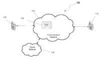
- FIG. 1is an illustration of an exemplary communication system in accordance with one or more embodiments of the invention
- FIG. 2is a block diagram of exemplary elements of a communication network in accordance with one or more embodiments of the invention.
- FIG. 3is a block diagram of exemplary elements of a user device in accordance with one or more embodiments of the invention.
- FIG. 4is a flow diagram of an exemplary contact information change process in accordance with embodiments of the invention.
- telephony deviceor “communication device” is intended to encompass any type of device capable of acting as a telephony device. This includes a traditional analog telephone, an Internet Protocol (IP) telephone, a computer running IP telephony software, cellular telephones, mobile telephony devices such as smartphones that can connect to a data network and run software applications, such as the Apple iPhoneTM, mobile telephony devices running the AndroidTM operating system, BlackberryTM mobile telephones, and mobile telephones running the Symbian® operating system.
- IPInternet Protocol
- mobile telephony devicessuch as smartphones that can connect to a data network and run software applications, such as the Apple iPhoneTM, mobile telephony devices running the AndroidTM operating system, BlackberryTM mobile telephones, and mobile telephones running the Symbian® operating system.
- certain devices that are not traditionally used as telephony devicesmay act as telephony devices once they are configured with appropriate client software.
- some devices that would not normally be considered telephony devicesmay become telephony devices or IP telephony devices once they are running appropriate software.
- One examplewould be a desktop or a laptop computer that is running software that can interact with an IP telephony system over a data network to conduct telephone calls.
- Another examplewould be a portable computing device, such as an Apple iPod TouchTM, which includes a speaker and a microphone.
- a software application loaded onto an Apple iPod TouchTMcan be run so that the Apple iPod Touch can interact with an IP telephony system to conduct a telephone call.
- the present technologyrelates to enhancing the notification and updating of contact information.
- the notification and updating of contact informationcan be implemented within a variety of systems and devices.
- the display and ordering of the contact informationcan, for example, be implemented at an IP telephony system responsible for managing contact information for one or more users.
- the implementationcan also be performed using a software application on one or more communication devices where the communication devices will modify the display and/or order of contact information.
- FIG. 1is an illustration of an exemplary communication system 100 including a communication network 110 , a first user device 105 and a second user device 115 .
- the communication network 110may be one or more networks such as Internet Protocol (IP) networks or public switched telephone networks (PSTN) used to connect the devices.
- IPInternet Protocol
- PSTNpublic switched telephone networks
- Communication network 110(or one or more of its constituent networks) may maintain user account information, including contact lists in a database 120 for example of the first user device 105 and the second user device 115 .
- FIG. 2elements of a communication network 110 are shown, including a processing unit 202 that may be used to provide various functions of the provider network including the methods discussed herein.
- the communication network 110may contain multiple processing units, databases and other elements and FIG. 2 is presented only as an illustration of an exemplary embodiment of the present invention.
- Processing unit 202is in communication with a contact lists database 120 which may store the contact lists of user accounts in communication network 110 .
- the contact lists database 120may, but need not, reside on the communication network and optionally may be remotely accessible (e.g., cloud based computing environment).
- the processing unit 202 shownmay be one of any form of a general purpose computer processor used in processing data in a provider network.
- the processing unit 202comprises a central processing unit (CPU) 204 .
- Communication network 110includes support circuits 203 for the processing unit 202 and a memory unit 201 .
- the processing unit 202also includes provisions for connecting the processing unit 202 to customer equipment, to service provider equipment and to IP networks, as well as possibly one or more input/output devices (not shown) for accessing the processing unit and/or performing ancillary or administrative functions related thereto.
- the memory unit 201may include a Contact Association Determination module (CAD) 211 and a Contact Association Message module (CAM) 212 in accordance with some embodiments of the present invention.
- CADContact Association Determination module
- CAMContact Association Message module
- the support circuits 203 and the CPU 204 for supporting the processing unit 202are connected in a conventional manner. These circuits include cache, power supplies, clock circuits, input/output circuitry and subsystems, and the like.
- the contact lists database 120may contain a plurality of individual contact lists for each user of communication network 110 .
- the contact lists in contact lists database 120may include attributes for each contact such as, phone numbers, addresses, email addresses, social media accounts, employer contact details and the like.
- contact informationmay be associated with a given user and, moreover, the user may have an individual contact list that further contains contact information for contacts in that list.
- the contact lists database 120is also capable of providing various other items of information associated with contacts in the individual contact list.
- John Smithmay not only have various contacts in his contact list, but may also have other lists of contacts such as a social network account for social network 130 in which contacts in his social network “connections” are listed.
- a user's individual contact listmay be connected to other contact lists from which contact information may be retrieved.
- the contactmay have provided the communication network 110 with permission to obtain information from the contact's account with the social network 130 .
- the contactmay have also provided the communication network 110 with the contact's credentials on the social network 130 , in the form of a user name and password, so that communication network 110 can log into the social network 130 to review and retrieve information from the contact's account on the social network 130 .
- communication network 110may have received authorization from a user to access certain information on a social network 130 , and communication network 110 may be able to access this information without actually logging into the social network 130 with the user's name and password.
- One skilled in the artcan understand that the above example of the social network 130 may be applied to other systems in which connections between individuals are established.
- a computer program or software routine (SW) 210when executed by the CPU 204 , causes the processing unit 202 to perform processes of the disclosed embodiments, and is generally stored in a memory or computer-readable medium, which may be one or more of readily available memory such as random access memory (RAM), read only memory (ROM), floppy disk, hard disk, flash memory or any other form of digital storage, local or remote, and is preferably of non-volatile nature.
- the software routinescould also be stored remotely from the CPU 204 .
- the softwarecould be resident on servers and memory devices that are located remotely from the CPU 204 , but which are accessible to the CPU 204 via a data network connection.
- the computer program or software routine 210when executed by the CPU 204 , transforms the general purpose computer into a specific purpose computer that performs one or more functions of the methods and systems of the disclosed embodiments.
- the processes of the disclosed embodimentsmay be discussed as being implemented as a software routine, some of the method steps that are disclosed therein may be performed in hardware as well as by a processor running software.
- the embodimentsmay be implemented in software as executed upon a computer system, in hardware as an application specific integrated circuit or other type of hardware implementation, or a combination of software and hardware.
- the software routine of the disclosed embodimentsis capable of being executed on any computer operating system, and is capable of being performed using any CPU architecture.
- FIG. 3depicts a block diagram of an exemplary user device 300 (e.g., 105 and 115 ) for identifying a set of associated contacts according to one or more embodiments.
- the user device 300comprises a Central Processing Unit (CPU) 320 , support circuits 310 , a memory 340 , and the display device 330 .
- the CPU 320may comprise one or more commercially available microprocessors or microcontrollers that facilitate data processing and storage.
- the various support circuits 310facilitate the operation of the CPU 320 and include one or more of clock circuits, power supplies, cache, input/output circuits, and the like.
- the memory 340comprises at least one of Read Only Memory (ROM), Random Access Memory (RAM), disk drive storage, optical storage, removable storage and/or the like.
- the display device 330may be a touch screen able to accept input from a user's finger or input from a stylus.
- the memory 340comprises an operating system 341 , contact list 342 , contact association determination module 343 , and contact association message module 344 .
- FIG. 4is a flow diagram of an exemplary contact information change process 400 in accordance with embodiments of the invention.
- a contact information change associated with a first contactis received.
- the contact information changeis received at first device 105 .
- the contact information changeis received at the communication network 110
- the contact information changemay be a result of the first contact obtaining a new job, a change in the first contact's physical address, changing a telephony service resulting in a new phone number or the like.
- the first usermay receive notification of the first contact information change from a message in electronic form such as an SMS or email or the first contact may inform the first user through a direct conversation by phone or in person for example.
- a first contact list containing the first contactis retrieved.
- the first contact listmay be retrieved from contact list 342 in memory 340 on first device 105 , or may be retrieved from contact list database 120 in communication with communication network 110 .
- the first contact listmay include a plurality of contacts, each contact associated with at least one contact attribute.
- Contact attributesmay include, for example, a contact name, an email address, a phone number, a physical address, a picture or a social networking or other affiliation ID.
- the contact information of a given contactcomprises the contact attributes associated with that contact.
- the contact information of the first contact in the first contact listis changed based on the received contact information change.
- the change in the contact informationmay be performed on first device 105 and may further be uploaded to database 120 , or may be applied directly to the contact list on database 120 and may be pushed to the first device 105 .
- step S 404it is determined whether the first contact is contained on a second contact list of a plurality of contact lists. The determination may be performed on first user device 105 or on communication network 110 .
- CAD module 343causes a search of the plurality of contacts in the first contact list 342 for a second user having a second contact list also containing the first contact for which the contact information change should be applied.
- CAD module 343sends an inquiry to each contact in the first contact list 342 to determine if a second contact list of a second user contains the first contact.
- the inquiryis processed through a CAD module contained on each of the inquired user devices.
- the inquiry from module 343is received at second device 115 which contains a CAD module through which the inquiry of the second contact list proceeds.
- the searchcompares the attributes of the first contact to identify the first contact in the second contact list.
- the attributesmay include, for example, a contact name, an email address, a phone number, a physical address, a picture or a social networking or other affiliation ID.
- CAD module 211in memory unit 201 causes a search of the plurality of contact lists in contact list database 120 for a second user having a second contact list also containing the first contact for which the contact information change should be applied.
- CAD module 211searches contact list database 120 for each individual contact list of each contact in the first contact list.
- the searchcompares the attributes of first contact with the attributes of each contact in the individual contact lists in database 120 to determine a second contact list containing the first contact.
- the attributesare searchable criteria and may include, for example, a contact name, an email address, a phone number, a physical address, a picture (searchable by facial recognition methods known in the art) or a social networking or other affiliation ID.
- the searchdetermines the second contact list of the second user that contains the first contact.
- the second useris identified.
- the second userwill be a contact in the first contact list.
- the second contact listis determined on communication network 110 the second user as owner of the second contact list is identified.
- more than one contact listmay be determined and more than one user may be identified.
- a messageis generated and provided to the second user on second user device 115 alerting the second user of the contact information change through Contact Association Message (CAM) module 344 .
- CAMContact Association Message
- On communication network 110a message is generated and sent to the second user alerting the second user of the contact information change through CAM module 212 .
- the second usermay accept the alert or decline the alert. If the second user declines the alert no change is made and the process ends. If the second user accepts the alert, the change of contact information is automatically applied to the second contact list at step S 408 .
- the applied changemay be generated from communication network 110 or from first user device 105 .
- multiple partiesmay be included in the determination of associated contacts.
Landscapes
- Engineering & Computer Science (AREA)
- Business, Economics & Management (AREA)
- Computer Networks & Wireless Communication (AREA)
- Signal Processing (AREA)
- Human Resources & Organizations (AREA)
- Theoretical Computer Science (AREA)
- Strategic Management (AREA)
- Physics & Mathematics (AREA)
- General Physics & Mathematics (AREA)
- Tourism & Hospitality (AREA)
- Economics (AREA)
- General Business, Economics & Management (AREA)
- Entrepreneurship & Innovation (AREA)
- Marketing (AREA)
- Data Mining & Analysis (AREA)
- Computing Systems (AREA)
- Operations Research (AREA)
- Quality & Reliability (AREA)
- Computer Hardware Design (AREA)
- Health & Medical Sciences (AREA)
- General Health & Medical Sciences (AREA)
- Primary Health Care (AREA)
- Databases & Information Systems (AREA)
- General Engineering & Computer Science (AREA)
- Information Transfer Between Computers (AREA)
- Telephonic Communication Services (AREA)
Abstract
Description
Claims (15)
Priority Applications (2)
| Application Number | Priority Date | Filing Date | Title |
|---|---|---|---|
| US13/907,201US8989359B2 (en) | 2013-05-31 | 2013-05-31 | Methods and systems for dynamically changing contact information |
| US14/599,694US9348858B2 (en) | 2013-05-31 | 2015-01-19 | Methods and systems for dynamically changing contact information |
Applications Claiming Priority (1)
| Application Number | Priority Date | Filing Date | Title |
|---|---|---|---|
| US13/907,201US8989359B2 (en) | 2013-05-31 | 2013-05-31 | Methods and systems for dynamically changing contact information |
Related Child Applications (1)
| Application Number | Title | Priority Date | Filing Date |
|---|---|---|---|
| US14/599,694ContinuationUS9348858B2 (en) | 2013-05-31 | 2015-01-19 | Methods and systems for dynamically changing contact information |
Publications (2)
| Publication Number | Publication Date |
|---|---|
| US20140357238A1 US20140357238A1 (en) | 2014-12-04 |
| US8989359B2true US8989359B2 (en) | 2015-03-24 |
Family
ID=51985663
Family Applications (2)
| Application Number | Title | Priority Date | Filing Date |
|---|---|---|---|
| US13/907,201ActiveUS8989359B2 (en) | 2013-05-31 | 2013-05-31 | Methods and systems for dynamically changing contact information |
| US14/599,694ActiveUS9348858B2 (en) | 2013-05-31 | 2015-01-19 | Methods and systems for dynamically changing contact information |
Family Applications After (1)
| Application Number | Title | Priority Date | Filing Date |
|---|---|---|---|
| US14/599,694ActiveUS9348858B2 (en) | 2013-05-31 | 2015-01-19 | Methods and systems for dynamically changing contact information |
Country Status (1)
| Country | Link |
|---|---|
| US (2) | US8989359B2 (en) |
Families Citing this family (7)
| Publication number | Priority date | Publication date | Assignee | Title |
|---|---|---|---|---|
| US11032108B2 (en)* | 2012-12-05 | 2021-06-08 | Microsoft Technology Licensing, Llc | Facilitating personas in communication exchange environments |
| US10051120B2 (en) | 2013-12-20 | 2018-08-14 | Ultratec, Inc. | Communication device and methods for use by hearing impaired |
| WO2015138320A1 (en)* | 2014-03-09 | 2015-09-17 | Vishal Gupta | Management of group-sourced contacts directories, systems and methods |
| US9438602B2 (en)* | 2014-04-03 | 2016-09-06 | Microsoft Technology Licensing, Llc | Evolving rule based contact exchange |
| RU2017104408A (en)* | 2017-02-10 | 2018-08-14 | СИГЕЙТ ТЕКНОЛОДЖИ ЭлЭлСи | COMPONENT DATA STORAGE TOPOLOGIES FOR DATA OBJECTS |
| US10659559B2 (en) | 2017-09-28 | 2020-05-19 | International Business Machines Corporation | Identifying and purging unwanted contacts from a contact list based on the construction of a persona profile |
| US11579771B2 (en) | 2020-05-12 | 2023-02-14 | Seagate Technology Llc | Data storage layouts |
Citations (6)
| Publication number | Priority date | Publication date | Assignee | Title |
|---|---|---|---|---|
| US20040128151A1 (en)* | 2002-12-31 | 2004-07-01 | Von Alan Mock | Method and apparatus for electronically updating changes in contact information |
| US20080005263A1 (en)* | 2006-06-28 | 2008-01-03 | Nokia Corporation | Method, Apparatus and Computer Program Product for Providing Automatic Delivery of Information to a Terminal |
| US20100076926A1 (en)* | 2008-09-10 | 2010-03-25 | International Business Machines Corporation | Method and system for dynamic contact information management in electronic communication devices |
| US20110231407A1 (en) | 2010-03-19 | 2011-09-22 | Microsoft Corporation | Dynamic contacts list management |
| WO2011150881A2 (en) | 2011-06-22 | 2011-12-08 | 华为终端有限公司 | Contact card management method and device used for mobile terminal |
| US20130244622A1 (en)* | 2012-03-16 | 2013-09-19 | Peter Matthew Hillier | Method and System for Transferring Mobile Device Contact Information |
Family Cites Families (1)
| Publication number | Priority date | Publication date | Assignee | Title |
|---|---|---|---|---|
| US8326361B2 (en)* | 1998-10-01 | 2012-12-04 | Lupine Investments Llc | Phone to phone data exchange |
- 2013
- 2013-05-31USUS13/907,201patent/US8989359B2/enactiveActive
- 2015
- 2015-01-19USUS14/599,694patent/US9348858B2/enactiveActive
Patent Citations (6)
| Publication number | Priority date | Publication date | Assignee | Title |
|---|---|---|---|---|
| US20040128151A1 (en)* | 2002-12-31 | 2004-07-01 | Von Alan Mock | Method and apparatus for electronically updating changes in contact information |
| US20080005263A1 (en)* | 2006-06-28 | 2008-01-03 | Nokia Corporation | Method, Apparatus and Computer Program Product for Providing Automatic Delivery of Information to a Terminal |
| US20100076926A1 (en)* | 2008-09-10 | 2010-03-25 | International Business Machines Corporation | Method and system for dynamic contact information management in electronic communication devices |
| US20110231407A1 (en) | 2010-03-19 | 2011-09-22 | Microsoft Corporation | Dynamic contacts list management |
| WO2011150881A2 (en) | 2011-06-22 | 2011-12-08 | 华为终端有限公司 | Contact card management method and device used for mobile terminal |
| US20130244622A1 (en)* | 2012-03-16 | 2013-09-19 | Peter Matthew Hillier | Method and System for Transferring Mobile Device Contact Information |
Also Published As
| Publication number | Publication date |
|---|---|
| US20150134604A1 (en) | 2015-05-14 |
| US20140357238A1 (en) | 2014-12-04 |
| US9348858B2 (en) | 2016-05-24 |
Similar Documents
| Publication | Publication Date | Title |
|---|---|---|
| US9348858B2 (en) | Methods and systems for dynamically changing contact information | |
| US8719280B1 (en) | Person-based information aggregation | |
| US10402585B2 (en) | Management of privacy policies | |
| US10091643B2 (en) | Method and apparatus for displaying associated information in electronic device | |
| US9380166B2 (en) | Dynamically constructing and updating social media status for use as ringback tones | |
| US10521480B2 (en) | Informative communication history | |
| US8620294B2 (en) | Mobile device dynamic background | |
| US10284699B2 (en) | Contact list availability prioritization | |
| US20080318560A1 (en) | Device Method and System for Handling Incoming Calls | |
| US9264870B2 (en) | Mobile terminal, server and calling method based on cloud contact list | |
| CN104394258B (en) | The method and apparatus that contact method change to communication object is handled | |
| CN104396341B (en) | Systems and methods to support contact reminders | |
| US9058586B2 (en) | Identification of a person located proximite to a contact identified in an electronic communication client | |
| CN109391658B (en) | Account data synchronization method and equipment, storage medium and terminal thereof | |
| US20180091460A1 (en) | Augmenting location of social media posts based on proximity of other posts | |
| CN104270496A (en) | Method and device for displaying calling party information | |
| US9913091B2 (en) | Providing contact data of second mobile devices proximate to a target person of a first mobile device | |
| US9854089B1 (en) | Managing and enabling interaction with communication information | |
| CN108390814A (en) | Method of enhancing display of personal contact information on mobile devices | |
| US20150024719A1 (en) | System and method for customized communications based upon contact relationships | |
| US9998849B2 (en) | Adaptable schema based payloads | |
| KR20150068717A (en) | Address Book Service System, Device, Method And Recording Medium | |
| KR20150096255A (en) | Recording Medium, Server Device and Method for Processing Contents | |
| CN108551528A (en) | Information processing method and device, electronic equipment and computer readable storage medium | |
| US20140270116A1 (en) | System and method for delivering a targeted message to a calling party |
Legal Events
| Date | Code | Title | Description |
|---|---|---|---|
| AS | Assignment | Owner name:VONAGE NETWORK LLC, NEW JERSEY Free format text:ASSIGNMENT OF ASSIGNORS INTEREST;ASSIGNORS:EFRATI, TZAHI;ZEHAVI, BOAZ;SIGNING DATES FROM 20130530 TO 20130531;REEL/FRAME:030525/0926 | |
| AS | Assignment | Owner name:JPMORGAN CHASE BANK, N.A., AS ADMINISTRATIVE AGENT, ILLINOIS Free format text:SECURITY INTEREST;ASSIGNORS:VONAGE HOLDINGS CORP.;VONAGE NETWORK LLC;VONAGE BUSINESS SOLUTIONS INC.;AND OTHERS;REEL/FRAME:033545/0424 Effective date:20140813 Owner name:JPMORGAN CHASE BANK, N.A., AS ADMINISTRATIVE AGENT Free format text:SECURITY INTEREST;ASSIGNORS:VONAGE HOLDINGS CORP.;VONAGE NETWORK LLC;VONAGE BUSINESS SOLUTIONS INC.;AND OTHERS;REEL/FRAME:033545/0424 Effective date:20140813 | |
| STCF | Information on status: patent grant | Free format text:PATENTED CASE | |
| AS | Assignment | Owner name:JPMORGAN CHASE BANK, N.A., AS ADMINISTRATIVE AGENT, ILLINOIS Free format text:SECURITY INTEREST;ASSIGNORS:VONAGE HOLDINGS CORP.;VONAGE AMERICA INC.;VONAGE BUSINESS SOLUTIONS, INC.;AND OTHERS;REEL/FRAME:036205/0485 Effective date:20150727 Owner name:JPMORGAN CHASE BANK, N.A., AS ADMINISTRATIVE AGENT Free format text:SECURITY INTEREST;ASSIGNORS:VONAGE HOLDINGS CORP.;VONAGE AMERICA INC.;VONAGE BUSINESS SOLUTIONS, INC.;AND OTHERS;REEL/FRAME:036205/0485 Effective date:20150727 | |
| AS | Assignment | Owner name:JPMORGAN CHASE BANK, N.A., AS ADMINISTRATIVE AGENT, ILLINOIS Free format text:CORRECTIVE ASSIGNMENT TO CORRECT THE PATENT APPLICATION NUMBER 13966486 PREVIOUSLY RECORDED ON REEL 033545 FRAME 0424. ASSIGNOR(S) HEREBY CONFIRMS THE SECURITY INTEREST;ASSIGNORS:VONAGE HOLDINGS CORP.;VONAGE NETWORK LLC;VONAGE BUSINESS SOLUTIONS INC.;AND OTHERS;REEL/FRAME:037570/0203 Effective date:20140813 Owner name:JPMORGAN CHASE BANK, N.A., AS ADMINISTRATIVE AGENT Free format text:CORRECTIVE ASSIGNMENT TO CORRECT THE PATENT APPLICATION NUMBER 13966486 PREVIOUSLY RECORDED ON REEL 033545 FRAME 0424. ASSIGNOR(S) HEREBY CONFIRMS THE SECURITY INTEREST;ASSIGNORS:VONAGE HOLDINGS CORP.;VONAGE NETWORK LLC;VONAGE BUSINESS SOLUTIONS INC.;AND OTHERS;REEL/FRAME:037570/0203 Effective date:20140813 | |
| AS | Assignment | Owner name:VONAGE BUSINESS INC., GEORGIA Free format text:ASSIGNMENT OF ASSIGNORS INTEREST;ASSIGNOR:VONAGE NETWORK LLC;REEL/FRAME:038328/0501 Effective date:20160304 | |
| AS | Assignment | Owner name:VONAGE BUSINESS INC., GEORGIA Free format text:CORRECTIVE ASSIGNMENT TO CORRECT THE LIST BY DELETING 13831728 13831785 14291602 13680382 14827548 14752086 13680067 14169385 14473289 14194220 14194438 14317743 PREVIOUSLY RECORDED ON REEL 038328 FRAME 501. ASSIGNOR(S) HEREBY CONFIRMS THE SALE, ASSIGNMENT, TRANSFER AND CONVEYANCE OF REMAINING PROPERTIES;ASSIGNOR:VONAGE NETWORK LLC;REEL/FRAME:040540/0702 Effective date:20160304 | |
| MAFP | Maintenance fee payment | Free format text:PAYMENT OF MAINTENANCE FEE, 4TH YEAR, LARGE ENTITY (ORIGINAL EVENT CODE: M1551); ENTITY STATUS OF PATENT OWNER: LARGE ENTITY Year of fee payment:4 | |
| AS | Assignment | Owner name:JPMORGAN CHASE BANK, N.A., AS ADMINISTRATIVE AGENT, ILLINOIS Free format text:SECURITY INTEREST;ASSIGNOR:VONAGE BUSINESS INC.;REEL/FRAME:047502/0432 Effective date:20181106 Owner name:JPMORGAN CHASE BANK, N.A., AS ADMINISTRATIVE AGENT Free format text:SECURITY INTEREST;ASSIGNOR:VONAGE BUSINESS INC.;REEL/FRAME:047502/0432 Effective date:20181106 | |
| AS | Assignment | Owner name:TOKBOX, INC., NEW JERSEY Free format text:RELEASE BY SECURED PARTY;ASSIGNOR:JPMORGAN CHASE BANK, N.A.;REEL/FRAME:061002/0340 Effective date:20220721 Owner name:NEXMO INC., NEW JERSEY Free format text:RELEASE BY SECURED PARTY;ASSIGNOR:JPMORGAN CHASE BANK, N.A.;REEL/FRAME:061002/0340 Effective date:20220721 Owner name:VONAGE BUSINESS INC., NEW JERSEY Free format text:RELEASE BY SECURED PARTY;ASSIGNOR:JPMORGAN CHASE BANK, N.A.;REEL/FRAME:061002/0340 Effective date:20220721 Owner name:VONAGE HOLDINGS CORP., NEW JERSEY Free format text:RELEASE BY SECURED PARTY;ASSIGNOR:JPMORGAN CHASE BANK, N.A.;REEL/FRAME:061002/0340 Effective date:20220721 Owner name:VONAGE AMERICA INC., NEW JERSEY Free format text:RELEASE BY SECURED PARTY;ASSIGNOR:JPMORGAN CHASE BANK, N.A.;REEL/FRAME:061002/0340 Effective date:20220721 | |
| MAFP | Maintenance fee payment | Free format text:PAYMENT OF MAINTENANCE FEE, 8TH YEAR, LARGE ENTITY (ORIGINAL EVENT CODE: M1552); ENTITY STATUS OF PATENT OWNER: LARGE ENTITY Year of fee payment:8 |