US8989212B2 - Systems and methods for coexistence of WLAN and bluetooth networks - Google Patents
Systems and methods for coexistence of WLAN and bluetooth networksDownload PDFInfo
- Publication number
- US8989212B2 US8989212B2US14/183,308US201414183308AUS8989212B2US 8989212 B2US8989212 B2US 8989212B2US 201414183308 AUS201414183308 AUS 201414183308AUS 8989212 B2US8989212 B2US 8989212B2
- Authority
- US
- United States
- Prior art keywords
- data
- network
- control
- frame
- slot
- Prior art date
- Legal status (The legal status is an assumption and is not a legal conclusion. Google has not performed a legal analysis and makes no representation as to the accuracy of the status listed.)
- Active
Links
Images


Classifications
- H—ELECTRICITY
- H04—ELECTRIC COMMUNICATION TECHNIQUE
- H04W—WIRELESS COMMUNICATION NETWORKS
- H04W52/00—Power management, e.g. Transmission Power Control [TPC] or power classes
- H04W52/02—Power saving arrangements
- H04W52/0203—Power saving arrangements in the radio access network or backbone network of wireless communication networks
- H04W52/0206—Power saving arrangements in the radio access network or backbone network of wireless communication networks in access points, e.g. base stations
- H—ELECTRICITY
- H04—ELECTRIC COMMUNICATION TECHNIQUE
- H04W—WIRELESS COMMUNICATION NETWORKS
- H04W52/00—Power management, e.g. Transmission Power Control [TPC] or power classes
- H04W52/02—Power saving arrangements
- H04W52/0209—Power saving arrangements in terminal devices
- H04W52/0212—Power saving arrangements in terminal devices managed by the network, e.g. network or access point is leader and terminal is follower
- H04W52/0216—Power saving arrangements in terminal devices managed by the network, e.g. network or access point is leader and terminal is follower using a pre-established activity schedule, e.g. traffic indication frame
- H—ELECTRICITY
- H04—ELECTRIC COMMUNICATION TECHNIQUE
- H04W—WIRELESS COMMUNICATION NETWORKS
- H04W52/00—Power management, e.g. Transmission Power Control [TPC] or power classes
- H04W52/02—Power saving arrangements
- H04W52/0209—Power saving arrangements in terminal devices
- H04W52/0212—Power saving arrangements in terminal devices managed by the network, e.g. network or access point is leader and terminal is follower
- H04W52/0219—Power saving arrangements in terminal devices managed by the network, e.g. network or access point is leader and terminal is follower where the power saving management affects multiple terminals
- H—ELECTRICITY
- H04—ELECTRIC COMMUNICATION TECHNIQUE
- H04W—WIRELESS COMMUNICATION NETWORKS
- H04W74/00—Wireless channel access
- H04W74/08—Non-scheduled access, e.g. ALOHA
- H04W74/0833—Random access procedures, e.g. with 4-step access
- H04W74/0841—Random access procedures, e.g. with 4-step access with collision treatment
- H04W74/085—Random access procedures, e.g. with 4-step access with collision treatment collision avoidance
- H—ELECTRICITY
- H04—ELECTRIC COMMUNICATION TECHNIQUE
- H04W—WIRELESS COMMUNICATION NETWORKS
- H04W88/00—Devices specially adapted for wireless communication networks, e.g. terminals, base stations or access point devices
- H04W88/02—Terminal devices
- H04W88/06—Terminal devices adapted for operation in multiple networks or having at least two operational modes, e.g. multi-mode terminals
- Y02B60/50—
- Y—GENERAL TAGGING OF NEW TECHNOLOGICAL DEVELOPMENTS; GENERAL TAGGING OF CROSS-SECTIONAL TECHNOLOGIES SPANNING OVER SEVERAL SECTIONS OF THE IPC; TECHNICAL SUBJECTS COVERED BY FORMER USPC CROSS-REFERENCE ART COLLECTIONS [XRACs] AND DIGESTS
- Y02—TECHNOLOGIES OR APPLICATIONS FOR MITIGATION OR ADAPTATION AGAINST CLIMATE CHANGE
- Y02D—CLIMATE CHANGE MITIGATION TECHNOLOGIES IN INFORMATION AND COMMUNICATION TECHNOLOGIES [ICT], I.E. INFORMATION AND COMMUNICATION TECHNOLOGIES AIMING AT THE REDUCTION OF THEIR OWN ENERGY USE
- Y02D30/00—Reducing energy consumption in communication networks
- Y02D30/70—Reducing energy consumption in communication networks in wireless communication networks
Definitions
- the present disclosuregenerally relates to wireless communications and more particularly relates to systems and methods for allowing coexistence of WLAN and Bluetooth networks.
- Wireless protocolssuch as Bluetooth and IEEE 802.11 define the logical interconnections of portable terminals having a variety of types of communication capabilities to host computers.
- the logical interconnectionsare based upon an infrastructure in which at least some of the terminals are capable of communicating wirelessly with another device when located within a predetermined range.
- the Bluetooth standardprovides a way to connect and exchange information between devices such as mobile phones, wireless headsets, laptops, PCs, printers, digital cameras, etc. over a secure, globally unlicensed short-range radio frequency.
- the protocoloperates in the license-free ISM (industrial, scientific and medical) band from 2.4-2.4835 GHz.
- ISMindustrial, scientific and medical
- Bluetoothhas become popular for such applications as wireless communication/control between mobile phones and a hands-free headsets.
- Other applicationsinclude wireless networking between PCs in addition to networking between PCs and output devices such as mouse devices and printers.
- the IEEE standard for 802.11is set out in “Wireless LAN Medium Access Control (MAC) and Physical Layer (PHY) Specifications” and is available from the IEEE Standards Department, Piscataway, N.J.
- the 802.11 standardpermits either IR or RF communications at 1 Mbps, 2 Mbps and higher data rates and performs a medium access technique similar to carrier sense multiple access/collision avoidance (CSMA/CA).
- CSMA/CAcarrier sense multiple access/collision avoidance
- the 802.11 standardfurther provides a power-save mode for battery-operated mobile stations, seamless roaming in a full cellular network, high throughput operation, diverse antenna systems designed to eliminate “dead spots,” and an easy interface to existing network infrastructures.
- one embodimentincludes a method for operating a wireless device in both a 802.11 network and a Bluetooth network.
- the methodcomprises monitoring transmission of Synchronous Connection Oriented (SCO) slots over the Bluetooth network, informing an access point (AP) in the 802.11 network not to transmit to the device before the end of an SCO slot, transmitting a power save trigger to the AP to retrieve buffered data from the AP, and transmitting data to the AP.
- SCOSynchronous Connection Oriented
- the devicecomprises a timer module and a communications module.
- the timer moduleis configured to monitor and determine the timing of Synchronous Connection Oriented (SCO) slots.
- the communications moduleis configured to notify an access point (AP) not to transmit data based on the timing of the SCO slots and transmit power save trigger frames to retrieve data from the AP.
- SCOSynchronous Connection Oriented
- Yet another embodimentincludes a method for operating a wireless device in both a 802.11 network and a Bluetooth network.
- the methodcomprises determining the beginning of a first SCO slot, setting a Network Allocation Vector (NAV) which ends before the end of the first SCO slot at an access point (AP) in the 802.11 network so that the AP stops transmitting data to the device, transmitting a power save trigger to the AP to retrieve buffered data from the AP, transmitting data to the AP, and receiving data from the AP at the end of the first SCO slot.
- NAVNetwork Allocation Vector
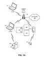
- FIG. 1Adepicts an embodiment of a system configured to coexist in both a WLAN and a Bluetooth network.
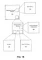
- FIG. 1Billustrates various components of the communications module depicted in FIG. 1A .
- FIG. 2depicts an embodiment of a method for coexisting in both a WLAN and a Bluetooth network.
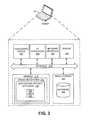
- FIG. 3illustrates an embodiment of the wireless device shown in FIG. 1A for executing the various steps depicted in FIG. 2 .
- FIGS. 4-7provide non-limiting examples where exemplary methods for coexisting in both a WLAN and a Bluetooth environment are incorporated.
- FIGS. 4A-Cillustrate transmissions in both the Bluetooth environment and the WLAN where the PHY rate in the WLAN is 1 Mbps.
- FIGS. 5A-Cillustrate transmissions where the PHY rate in the WLAN network is 2 Mbps.
- FIGS. 6A-Cillustrate transmissions where the PHY rate in the WLAN network is 6 Mbps.
- FIGS. 7A-Cillustrate transmissions where the PHY rate in the WLAN network is 54 Mbps.
- Bluetooth and 802.11 WLANsshare the same unlicensed frequency band, in particular the 2.4 GHz band. Consequently, this can lead to collisions between the two networks.
- one application that relies on the coexistence of Bluetooth and WLAN devicesinvolves placing a voice call using a Bluetooth wireless earpiece and a handheld device (via SCO slots), where the voice data is then routed over a WLAN to an access point (AP) and ultimately through a wired long distance infrastructure, such as the Internet.
- APaccess point
- the IEEE 802.15.2-2003 Recommended Practicesaddresses the issue of coexistence of Wireless Personal Area Networks (WPAN) with other wireless devices operating in unlicensed frequency bands such as those utilized by wireless local area networks (WLAN).
- the IEEE 802.15 Coexistence Task Group 2 (TG2)developed a Recommended Practices to facilitate coexistence of WPAN and WLAN.
- the Task Groupspecifically developed a Coexistence Model to quantify the mutual interference of a WLAN and a WPAN.
- the Task Groupalso developed a set of Coexistence Mechanisms to facilitate coexistence of WLAN and WPAN devices.
- the IEEE 802.15.2 Recommended Practicesdefine an interface between collocated Bluetooth and WLAN units, where each Bluetooth unit can request channel access and provide an indication of activity.
- the WLANmay determine and predict the timing of Bluetooth SCO (Synchronous Connection Oriented) slots, which are used to convey high priority traffic such as voice.
- SCOSerial Connection Oriented
- the WLAN clientBased on the SCO slot timing obtained via the PTA interface, the WLAN client can time its transmissions so as to not interfere with the SCO slows.
- the timing of transmissions from the APis beyond the immediate control of the WLAN client.
- the time between successive SCO slotsis used for the trigger frame, the uplink voice frame, the AP turnaround time, and the downlink voice frame.
- the time required for these eventswill exceed the time between SCO slots, effectively barring these PHY rates for use in this scenario.
- Bluetooth devicesuse high quality voice transmissions. This may comprise HV3 (High Quality Voice) over a SCO link, for instance.
- HV3High Quality Voice
- the uplink and downlink SCO slotstake 1250 ⁇ s to complete where the time between SCO slots is 2500 ⁇ s.
- the Network Allocation Vectorrelates to a method for avoiding collisions in a shared transmission medium.
- Each client that wants to transmit data using the shared mediummay first perform a RTS (Request to Send) with a NAV that indicates the time required to complete the desired transmission. If no collision is detected and if a clear-to-send (CTS) packet is sent, the shared medium is considered to be allocated to the client that generated the RTS during the time specified by the NAV.
- the RTS and the CTSeach set a NAV locally around the respective senders of the RTS and the CTS.
- the NAVcan be reset by the AP through the transmission of a Contention Free End (CF-End) frame, but for 802.11n, clients are also allowed to reset a NAV by transmitting a CF-End frame.
- CF-EndContention Free End
- Embodiments of systems and methods described hereinseek to address the perceived shortcomings discussed earlier by configuring the WLAN client to indirectly influence the time of transmissions from the AP.
- the transmission of PSM trigger framesare timed such that uplink voice transmissions over the WLAN may be conducted before the beginning of the next SCO slot.
- thismay involve sending a PS-Poll trigger frame or U-APSD trigger frame.
- a short frameis included which sets a NAV at the AP that ends after the pending SCO slot.
- NAV protectionuses the IEEE 802.11 virtual carrier sense mechanism to cause stations that detect the frame to set their internal carrier sense to the “busy” state, even if they do not sense radio frequency energy during the NAV protection interval.
- an exemplary method for coexisting in both a 802.11-based network and a Bluetooth networkcomprises monitoring transmission of SCO slots sent over the Bluetooth network to determine timing of the SCO slots.
- the methodfurther comprises transmitting a power save trigger frame according to the determined timing and setting a NAV to stop transmission from an access point.
- the power save trigger frameis transmitted from a client to the access point between SCO slots, uplink transmission over the 802.11-based network takes place between SCO slots, and downlink transmission begins after the NAV expires.
- each WLAN voice transmission(both uplink and downlink) can then utilize almost the entire period between successive SCO slots, while the AP turnaround time is timed to coincide with the SCO slot itself.
- the SCO slotbecomes protected from interference by other WLAN nodes.
- Setting a NAV at the APrequires the transmission of a frame which is not addressed at the AP, and which contains a Duration value inside the MAC header. For some embodiments, this can be a CTS frame addressed at the client.
- the CTSis transmitted at a rate that can be decoded by the AP. A lower rate is not required because the main purpose is to influence the timing of downlink transmissions at the AP, while setting a NAV in a too large area around the client is avoided.
- directional PHY mechanismssuch as beamforming can be used to further focus setting of the NAV only at the AP.
- a new methodis added to the IEEE 802.11 standard (or at WFA (WiFi Alliance) to set a temporary transmission restriction at the AP, which applies only to the related client.
- the frameshould be addressed at the AP.
- the transmission restriction timing informationmay even be included inside the MAC header of the uplink data frame which is transmitted to the AP.
- FIG. 1Adepicts an embodiment of a system configured to coexist in both a WLAN and a Bluetooth network.
- FIG. 1Aillustrates atypical network configuration for communicating data between clients via an access point in a WLAN or 802.11-based network.
- a network 140may be coupled to access point 130 .
- the network 140may be the Internet, for example.
- the access point 130can be configured to provide wireless communications to various wireless devices of clients 110 , 120 , 150 .
- the clients 110 , 120 , 150may be a personal computer, a laptop computer, a mobile phone, a Personal Digital Assistant, and/or other device configured for wirelessly sending and/or receiving data.
- the access points 130may be configured to provide WIFI services, WiMAX services, wireless SIP services and/or other wireless communication services.
- the clients 110 , 120may be configured for WIFI communications (including, but not limited to 802.11, 802.11b, 802.11a/b, 802.11g, and/or 802.11n).
- FIG. 1Aalso depicts various Bluetooth devices connected over a Bluetooth connection.
- a printer 180 with an integrated Bluetooth interfaceis coupled to the client 120 , which in addition to having a WLAN interface, also has a Bluetooth interface.
- FIG. 1Aalso depicts a mobile phone 150 .
- the mobile phone 150may be a smartphone capable of interfacing with both 802.11-based networks and Bluetooth-enabled devices such as the wireless earpiece 130 shown.
- the smartphone 150may, for example, have connectivity to the Internet through the WLAN and provide mobile voices services through use of the earpiece 130 .
- the smartphone 150is a client connected to the same wireless AP 130 that the other two clients 110 , 120 are connected to.
- one application that relies on the coexistence of Bluetooth and WLAN devicesinvolves placing voice calls using a Bluetooth wireless earpiece 130 (such as the one depicted in FIG. 1 ) and a handheld device 150 , where voice data is then routed over a WLAN to an AP 130 and ultimately through a wired long distance infrastructure, such as the Internet.
- a Bluetooth wireless earpiece 130such as the one depicted in FIG. 1
- a handheld device 150where voice data is then routed over a WLAN to an AP 130 and ultimately through a wired long distance infrastructure, such as the Internet.
- voice-over-WLANor VOWLAN
- both Bluetooth and WiFi servicesneed to operate simultaneously in the same device.
- the client 120may include a timer module 160 configured to monitor and determine the timing of Synchronous Connection Oriented (SCO) slots transmitted over the Bluetooth network.
- the client 120may further include a communications module 170 configured to transmit power save trigger frames according to the timing of SCO slots such that the uplink transmission over the 802.11-based network ends before the next SCO slot.
- the modules 160 , 170may be implemented in software, hardware, or a combination of both.
- FIG. 1Billustrates various components of the communications module depicted in FIG. 1A .
- the communications module 170may comprise logic 190 configured to set a Network Allocation Vector (NAV) such that the access point ceases transmission of data.
- NAVNetwork Allocation Vector
- the NAVis set so that the time in which it expires aligns with the end of an SCO slot.
- the communications module 170further comprises logic 192 configured to send a clear-to-send (CTS) frame which specifies the duration of the NAV. Upon transmission of the CTS frame by logic 192 , the NAV is set and expires upon reaching the time specified.
- the communications module 170may further comprise logic 194 configured to receive downlink transmissions between successive SCO slots.
- FIG. 2depicts an embodiment of a method for coexisting in both a WLAN and a Bluetooth network.
- step 210the transmission of SCO slots sent over the Bluetooth network is monitored.
- timing informationis derived in step 220 .
- step 230power save trigger frames are then transmitted according to the derived timing.
- a CTS framemay be used to specify the duration of the NAV (step 240 ).
- step 250a NAV is set so that it expires at the end of an SCO slot.
- uplink datais sent during the time duration between SCO slots so that interference can be avoided between the two protocols (step 260 ).
- transmission of downlink datais timed such that it takes place between SCO slots (step 270 ).
- FIG. 3illustrates an embodiment of the wireless device shown in FIG. 1A for executing the various steps depicted in FIG. 2 .
- the client 120can comprise any one of a wide variety of wired and/or wireless computing devices, such as a desktop computer, portable computer, dedicated server computer, multiprocessor computing device, cellular telephone, personal digital assistant (PDA), handheld or pen based computer, embedded appliance and so forth. Irrespective of its specific arrangement, the client 120 can, for instance, comprise memory 312 , a processing device 302 , a number of input/output interfaces 304 , a network interface 306 , a display 308 , and mass storage 324 , wherein each of these devices are connected across a data bus 310 .
- Processing device 302can include any custom made or commercially available processor, a central processing unit (CPU) or an auxiliary processor among several processors associated with the computing device 102 , a semiconductor based microprocessor (in the form of a microchip), a macroprocessor, one or more application specific integrated circuits (ASICs), a plurality of suitably configured digital logic gates, and other well known electrical configurations comprising discrete elements both individually and in various combinations to coordinate the overall operation of the computing system.
- CPUcentral processing unit
- ASICsapplication specific integrated circuits
- the memory 312can include any one of a combination of volatile memory elements (e.g., random-access memory (RAM, such as DRAM, and SRAM, etc.)) and nonvolatile memory elements (e.g., ROM, hard drive, tape, CDROM, etc.).
- the memory 312typically comprises a native operating system 314 , one or more native applications, emulation systems, or emulated applications for any of a variety of operating systems and/or emulated hardware platforms, emulated operating systems, etc.
- the applicationsmay include application specific software 122 such as the timer module 160 and communications module 170 depicted in FIG. 1 . It should be noted, however, that the timer module 160 and communications module 170 can also be implemented in hardware or a combination of software and hardware.
- the memory 312can, and typically will, comprise other components which have been omitted for purposes of brevity.
- Input/output interfaces 304provide any number of interfaces for the input and output of data.
- client 120comprises a personal computer
- these componentsmay interface with user input device 304 , which may be a keyboard or a mouse.
- client 120comprises a handheld device (e.g., PDA, mobile telephone)
- these componentsmay interface with function keys or buttons, a touch sensitive screen, a stylist, etc.
- Display 308can comprise a computer monitor or a plasma screen for a PC or a liquid crystal display (LCD) on a hand held device, for example.
- LCDliquid crystal display
- network interface device 306comprises various components used to transmit and/or receive data over a network environment.
- the network interface 306may include a device that can communicate with both inputs and outputs, for instance, a modulator/demodulator (e.g., a modem), wireless (e.g., radio frequency (RF)) transceiver, a telephonic interface, a bridge, a router, network card, etc.).
- the client 120may further comprise mass storage 326 .
- the mass storage 326may include a database 328 to store and manage such data as metadata.
- FIGS. 4A-C , 5 A-C, 6 A-C, and 7 A-Cprovide non-limiting examples where exemplary methods for coexisting in both a WLAN and a Bluetooth environment described earlier are incorporated.
- the figuresillustrate use of a PS-Poll trigger frame, a CAM toggling scheme, and a U-APSD trigger frame to indirectly influence the time of transmissions from the AP.
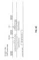
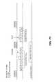
- FIGS. 4A-Cillustrate transmissions in both the Bluetooth environment and the WLAN where the PHY rate in the WLAN is 1 Mbps.
- FIGS. 5A-Cillustrate transmissions where the PHY rate in the WLAN network is 2 Mbps.
- FIGS. 6A-Cillustrate transmissions where the PHY rate in the WLAN network is 6 Mbps.
- FIGS. 7A-Cillustrate transmissions where the PHY rate in the WLAN network is 54 Mbps.
- 802.11 compliant devices 110 , 120 , 150such as the ones depicted in FIG. 1A switch to a power save mode when not engaged in network communication.
- An access point 130buffers incoming data for such power-saving 802.11 compliant devices 110 , 120 , 150 and sends a beacon signal after a pre-defined time interval indicating the presence of buffered data for the power-saving 802.11 compliant devices 110 , 120 , 150 .
- Such devices 110 , 120 , 150switch from the power save mode to an active mode to receive and check the beacon signal for any indication of buffered data at the access point for the device. If there is any indication of buffered data at the access point, the device sends a Power Save-Poll (PS-Poll) to the access point 130 requesting the access point 130 to send the buffered data to the device 110 , 120 , 150 .
- PS-PollPower Save-Poll
- the access point 130responds by transmitting buffered data to the device 110 , 120 , 150 .
- the buffered datais transmitted in the form of data frames, which carry an indication of any additional buffered data at the access point. If there is such an indication, then the device 110 , 120 , 150 transmits another PS-Poll and receives the additional buffered data. This process repeats until there is no further indication of additional buffered data at the access point. Thereafter, the device 110 , 120 , 150 switches back to the power save mode, thereby conserving power.
- FIGS. 4A , 5 A, 6 A, and 7 Adepict use of the PS-Poll trigger frames for varying PHY rates ranging from 1 Mbps to 54 Mbps.
- the CTS 404 and PS-Poll 406 framesare sent one inter-SCO gap earlier, as depicted in FIG. 4A .
- the devicesends a CTS frame 404 and a PS-Poll frame 406 to the access point to request the access point to send buffered data to the device.
- the access pointresponds to the PS-Poll frame with an ACK frame after an SIFS (short interframe space) 408 delay.
- SIFSshort interframe space
- Uplink transmission 410takes place in the ensuing gap, and downlink transmission follows accordingly. It should also be noted that upon transmission of the CTS frame 404 , the NAV is set for 3,157 ⁇ s and expires at the end of an SCO slot at time instance 402 . During this time interval, no traffic is sent from the access point. As noted earlier, the response from the access point, which includes buffered data, is delayed until after this pending SCO slot.
- the interval times and/or data frame timesmay differ from those described with regard to the figures shown. Similarly, the amount of data transmitted in a data frame may differ, depending on the particular configuration. The values given for these parameters are included for purposes of illustration and are not intended to limit the scope of this disclosure.
- Wireless devicesgenerally have two power consumption modes: Constantly Awake Mode (CAM) and Power Save Polling (PSP). Power Save Polling causes the card to “sleep” on a periodic basis, turning its radio signal off.
- CAMConstantly Awake Mode
- PSPPower Save Polling
- FIGS. 4B , 5 B, 6 B, and 7 Billustrate use of CAM toggling to achieve coexistence of Bluetooth and WLAN VoIP transmissions.
- the devicesends a CTS frame which specifies the duration of the NAV.
- the duration of the NAVis 4,981 ⁇ s.
- the NAVUpon transmission of the CTS frame 420 , the NAV is set and expires upon reaching the time specified (time instant 422 which aligns with the end of an SCO slot). At this time, the access point generates downlink traffic to the device. In the next inter-SCO gap after sending the CTS, the device sends uplink data with the PM bit not set so that the AP will send downlink traffic after expiration of the NAV.
- Unscheduled Asynchronous Power Save Deliveryis a power save mechanism for 802.11-based systems in which the communications device 110 , 120 , 150 sends a trigger frame to an access point 130 (for instance an uplink voice frame), which is then acknowledged by the access point 130 .
- Transmission of the trigger frameis depicted in FIGS. 4C , 5 C, 6 C, and 7 C.
- the access pointresponds with the buffered downlink traffic. The time for the response to begin may take some time, because the buffered data may be stored in a portion of the access point's memory, which may have higher access latency, due to the design of the access point and the possibly large amount of data to buffer at the access point.
- the clientmay remain in a normal operation mode and remain in receive mode until the client receives a response from the AP.
- the APmay set an End Of Service Period (EOSP) bit 432 , which is an indication for the clients that the service period has ended and that it can return to a power save mode, where at least one of the active components utilized during normal operation is deactivated during a period of communicative inactivity.
- EOSPEnd Of Service Period
- PS-Poll based power savingmay operate in a similar fashion, except that there may only be a single downlink Media Access Control (MAC) Protocol Data Unit (MPDU).
- MACMedia Access Control
- MPDUProtocol Data Unit
- HV3 data framesare sent in a Bluetooth environment at regular intervals of 2500 ⁇ s, with the data frames being sent at 1250 ⁇ s.
- the duration of each SCO slotis usually long enough for the AP to collect downlink data from its power-save repository.
- the probabilityis high that the AP will send the response soon after the end of an SCO slot (i.e., the NAV protected period).
- the probabilityis high that the AP will complete its transmission before the start of the next SCO slot, and therefore, collisions are avoided.
- the turnaround time of the APis relatively short and the WLAN PHY rate is relatively high, it is possible for the entire uplink and downlink VoIP exchange to take place in between two successive inter-SCO gaps.
- the uplink transmission and the downlink transmissionmay be split across consecutive inter-SCO gaps.
Landscapes
- Engineering & Computer Science (AREA)
- Computer Networks & Wireless Communication (AREA)
- Signal Processing (AREA)
- Mobile Radio Communication Systems (AREA)
Abstract
Description
Claims (20)
Priority Applications (1)
| Application Number | Priority Date | Filing Date | Title |
|---|---|---|---|
| US14/183,308US8989212B2 (en) | 2006-11-30 | 2014-02-18 | Systems and methods for coexistence of WLAN and bluetooth networks |
Applications Claiming Priority (3)
| Application Number | Priority Date | Filing Date | Title |
|---|---|---|---|
| US86179906P | 2006-11-30 | 2006-11-30 | |
| US11/947,946US8654773B2 (en) | 2006-11-30 | 2007-11-30 | Systems and methods for coexistence of WLAN and bluetooth networks |
| US14/183,308US8989212B2 (en) | 2006-11-30 | 2014-02-18 | Systems and methods for coexistence of WLAN and bluetooth networks |
Related Parent Applications (1)
| Application Number | Title | Priority Date | Filing Date |
|---|---|---|---|
| US11/947,946ContinuationUS8654773B2 (en) | 2006-11-30 | 2007-11-30 | Systems and methods for coexistence of WLAN and bluetooth networks |
Publications (2)
| Publication Number | Publication Date |
|---|---|
| US20140169249A1 US20140169249A1 (en) | 2014-06-19 |
| US8989212B2true US8989212B2 (en) | 2015-03-24 |
Family
ID=39468738
Family Applications (2)
| Application Number | Title | Priority Date | Filing Date |
|---|---|---|---|
| US11/947,946Active2030-11-05US8654773B2 (en) | 2006-11-30 | 2007-11-30 | Systems and methods for coexistence of WLAN and bluetooth networks |
| US14/183,308ActiveUS8989212B2 (en) | 2006-11-30 | 2014-02-18 | Systems and methods for coexistence of WLAN and bluetooth networks |
Family Applications Before (1)
| Application Number | Title | Priority Date | Filing Date |
|---|---|---|---|
| US11/947,946Active2030-11-05US8654773B2 (en) | 2006-11-30 | 2007-11-30 | Systems and methods for coexistence of WLAN and bluetooth networks |
Country Status (2)
| Country | Link |
|---|---|
| US (2) | US8654773B2 (en) |
| WO (1) | WO2008067505A2 (en) |
Cited By (1)
| Publication number | Priority date | Publication date | Assignee | Title |
|---|---|---|---|---|
| US20170318534A1 (en)* | 2014-12-08 | 2017-11-02 | Denso Corporation | Portable terminal, portable terminal operation system, and communication control method |
Families Citing this family (79)
| Publication number | Priority date | Publication date | Assignee | Title |
|---|---|---|---|---|
| US7693117B2 (en)* | 2002-12-16 | 2010-04-06 | Avaya Inc. | Power-saving mechanism for periodic traffic streams in wireless local-area networks |
| US7774015B2 (en)* | 2006-12-11 | 2010-08-10 | General Instrument Corporation | Power control apparatus and method for supporting seamless mobility |
| CA2673208C (en)* | 2007-01-15 | 2014-03-11 | Research In Motion Limited | Fragmenting large packets in the presence of high priority packets |
| US8249030B2 (en)* | 2007-03-23 | 2012-08-21 | Intel Corporation | Adapting TXOP requests for multi-radio platforms |
| JP4238918B2 (en)* | 2007-04-02 | 2009-03-18 | 沖電気工業株式会社 | Communication control device, communication control method, communication control program, node, and communication system |
| US8144676B2 (en)* | 2007-09-04 | 2012-03-27 | Conexant Systems, Inc. | Network allocation |
| US8577305B1 (en) | 2007-09-21 | 2013-11-05 | Marvell International Ltd. | Circuits and methods for generating oscillating signals |
| US20090103474A1 (en)* | 2007-10-18 | 2009-04-23 | Gang Lu | System and method for improving bluetooth performance in the presence of a coexistent, non-bluetooth, wireless device |
| US8588705B1 (en) | 2007-12-11 | 2013-11-19 | Marvell International Ltd. | System and method of determining Power over Ethernet impairment |
| US8886140B2 (en) | 2008-10-14 | 2014-11-11 | Texas Instruments Incorporated | Systems and methods for silencing wireless devices |
| US8072913B2 (en)* | 2008-02-03 | 2011-12-06 | Broadcom Corporation | Collaborative coexistence of co-located mobile WiMAX, wireless LAN, and/or bluetooth radios |
| WO2009098646A1 (en)* | 2008-02-06 | 2009-08-13 | Nxp B.V. | Wireless communications arrangement, network and approach therefor |
| TWI369099B (en)* | 2008-05-08 | 2012-07-21 | Inst Information Industry | Relay station, access point, transmission method, and tangible machine-readable medium thereof for use in a wireless mesh network |
| US8315564B2 (en) | 2008-06-16 | 2012-11-20 | Marvell World Trade Ltd. | Short-range wireless communication |
| US8155695B2 (en) | 2008-07-29 | 2012-04-10 | Sony Ericsson Mobile Communications Ab | Apparatus and method to improve WLAN performance in a dual WLAN modality environment |
| US8472968B1 (en) | 2008-08-11 | 2013-06-25 | Marvell International Ltd. | Location-based detection of interference in cellular communications systems |
| KR20110058807A (en) | 2008-08-14 | 2011-06-01 | 코닌클리케 필립스 일렉트로닉스 엔.브이. | System, method and apparatus for interference avoidance between two wireless communication networks |
| US8134992B1 (en)* | 2008-09-24 | 2012-03-13 | Qualcomm Atheros, Inc. | Message-based coexistence interface between wireless devices |
| US20100091717A1 (en)* | 2008-10-14 | 2010-04-15 | Motorola, Inc. | Method to quite hidden nodes |
| US8472427B1 (en) | 2009-04-06 | 2013-06-25 | Marvell International Ltd. | Packet exchange arbitration for coexisting radios |
| TW201044818A (en)* | 2009-06-01 | 2010-12-16 | Ralink Technology Corp | Method and apparatus for receiving packets |
| CN101909302B (en) | 2009-06-03 | 2013-10-09 | 华为技术有限公司 | A method and device for dynamic spectrum allocation |
| US8184566B2 (en)* | 2009-06-05 | 2012-05-22 | Mediatek Inc. | Systems for wireless local area network (WLAN) transmission and for coexistence of WLAN and another type of wireless transmission and methods thereof |
| US8442581B2 (en)* | 2009-06-05 | 2013-05-14 | Mediatek Inc. | System for the coexistence between a plurality of wireless communication modules |
| US8711823B2 (en) | 2009-06-05 | 2014-04-29 | Mediatek Inc. | System for wireless local area network (WLAN) transmission and for coexistence of WLAN and another type of wireless transmission and methods thereof |
| CN101909000A (en)* | 2009-06-05 | 2010-12-08 | 雷凌科技股份有限公司 | Method and device for packet reception |
| US9236896B2 (en)* | 2009-07-09 | 2016-01-12 | Mediatek Inc. | Systems and methods for coexistence of a plurality of wireless communications modules |
| US9504092B2 (en) | 2009-07-09 | 2016-11-22 | Mediatek Inc. | System for the coexistence between a plurality of wireless communications modules sharing single antenna |
| US9025583B2 (en)* | 2009-07-09 | 2015-05-05 | Mediatek Inc. | System for the coexistence between a plurality of wireless communication module sharing single antenna |
| US9130605B2 (en)* | 2009-07-09 | 2015-09-08 | Mediatek Inc. | Systems and methods for coexistence between plurality of wireless communications modules sharing single antenna |
| GB2465650B (en)* | 2009-07-27 | 2010-10-13 | Cambridge Silicon Radio Ltd | Wireless network protocol coexistence |
| US9066369B1 (en) | 2009-09-16 | 2015-06-23 | Marvell International Ltd. | Coexisting radio communication |
| US8340578B2 (en) | 2009-10-05 | 2012-12-25 | Apple Inc. | Methods and apparatus for enhanced coexistence algorithms in wireless systems |
| US8693569B2 (en) | 2009-10-19 | 2014-04-08 | Apple Inc. | Methods and apparatus for dynamic wireless device coexistence |
| US8249031B1 (en) | 2009-11-17 | 2012-08-21 | Qualcomm Atheros, Inc. | Aggregation coexistence mechanism for wireless devices |
| US8462622B2 (en) | 2009-12-08 | 2013-06-11 | Qualcomm Incorporated | Detection of co-located interference in a multi-radio coexistence environment |
| US8606184B1 (en) | 2009-12-08 | 2013-12-10 | Qualcomm Incorporated | Coexistence message processing mechanism for wireless devices |
| US8520586B1 (en) | 2009-12-16 | 2013-08-27 | Qualcomm Incorporated | Discovery and connection coexistence mechanism for wireless devices |
| US8599737B2 (en)* | 2010-04-02 | 2013-12-03 | Mediatek Inc. | Methods for coordinating transmission and reception operations of radio modules in a communications apparatus and communication apparatuses utilizing the same |
| US8879580B2 (en)* | 2010-06-17 | 2014-11-04 | Texas Instruments Incorporated | Enhancing packet aggregation performance in coexisting wireless networks |
| US9030971B2 (en)* | 2010-07-20 | 2015-05-12 | Qualcomm Incorporated | Simultaneous operation of short range wireless systems with a mobile wireless broadband system |
| US8599709B2 (en) | 2011-02-10 | 2013-12-03 | Apple Inc. | Methods and apparatus for wireless coexistence based on transceiver chain emphasis |
| US8493897B2 (en) | 2011-02-11 | 2013-07-23 | Mediatek Inc. | Systems and methods for providing categorized channel reservation |
| KR101507867B1 (en)* | 2011-06-03 | 2015-04-07 | 엘지전자 주식회사 | Network communication method and terminal in a heterogeneous network environment |
| US8553603B2 (en) | 2011-06-09 | 2013-10-08 | Symbol Technologies, Inc. | Client bridge between wired and wireless communication networks |
| US9001720B2 (en) | 2011-08-31 | 2015-04-07 | Maarten Menzo Wentink | Power save with data fetch time, with end of data indication, and with more data acknowledgement |
| US9125216B1 (en) | 2011-09-28 | 2015-09-01 | Marvell International Ltd. | Method and apparatus for avoiding interference among multiple radios |
| TWI466561B (en)* | 2011-10-25 | 2014-12-21 | Acer Inc | Wireless device wireless connection method |
| US9565690B2 (en) | 2011-11-30 | 2017-02-07 | Nokia Technologies Oy | Medium access control method enhancement |
| US20130176998A1 (en)* | 2012-01-06 | 2013-07-11 | Nokia Corporation | Mechanism For Coexistence Between Wireless Networks |
| WO2013119810A1 (en)* | 2012-02-07 | 2013-08-15 | Marvell World Trade Ltd. | Method and apparatus for multi-network communication |
| US8995553B2 (en)* | 2012-06-08 | 2015-03-31 | Apple Inc. | Methods and apparatus for mitigating interference in aggressive form factor designs |
| US9450649B2 (en) | 2012-07-02 | 2016-09-20 | Marvell World Trade Ltd. | Shaping near-field transmission signals |
| US9585091B2 (en) | 2012-08-17 | 2017-02-28 | Qualcomm Incorporated | Systems and methods for low power wake up signal and operations for WLAN |
| GB2506367B (en) | 2012-09-26 | 2015-01-07 | Imagination Tech Ltd | Method and system for wirelessly transmitting data |
| US9191890B2 (en)* | 2012-10-24 | 2015-11-17 | Qualcomm Incorporated | Systems and methods for low power operations on wireless networks |
| US9191891B2 (en) | 2012-11-02 | 2015-11-17 | Qualcomm Incorporated | Systems and methods for low power wake-up signal implementation and operations for WLAN |
| US20140164562A1 (en)* | 2012-12-10 | 2014-06-12 | Apple, Inc. | Forming computer system networks based on acoustic signals |
| US9490548B2 (en)* | 2013-02-26 | 2016-11-08 | Qualcomm Incorporated | Wireless device with antenna array and separate antenna |
| WO2014162194A1 (en)* | 2013-04-01 | 2014-10-09 | Marvell World Trade Ltd. | Termination of wireless communication uplink periods to facilitate reception of other wireless communications |
| US9668297B2 (en) | 2013-05-29 | 2017-05-30 | Texas Instruments Incorporated | BLE scatternet system and method |
| US9241370B2 (en)* | 2013-06-14 | 2016-01-19 | Netgear, Inc. | Method and apparatus for implementing coexistence of multiple homogeneous radios and traffic management therein |
| US20150024687A1 (en)* | 2013-07-22 | 2015-01-22 | Qualcomm Incorporated | Systems and methods for coexistence between multiple wireless networks |
| US9608678B1 (en) | 2013-12-19 | 2017-03-28 | Marvell International Ltd. | Method and apparatus for mitigating interference between wireless local area network (WLAN) communications and cellular communications |
| US11310614B2 (en)* | 2014-01-17 | 2022-04-19 | Proctor Consulting, LLC | Smart hub |
| TWI565232B (en)* | 2014-04-16 | 2017-01-01 | 微晶片科技公司 | Gain control method, module, and wireless signal receiver using the same |
| JP6336336B2 (en)* | 2014-06-13 | 2018-06-06 | キヤノン株式会社 | Communication device, control method, and program |
| KR102096431B1 (en)* | 2014-06-20 | 2020-04-03 | 주식회사 윌러스표준기술연구소 | Wireless communication method for saving power and wireless communication terminal using same |
| JP6586091B2 (en)* | 2014-08-04 | 2019-10-02 | シャープ株式会社 | Terminal apparatus and method |
| US9730162B2 (en)* | 2014-09-03 | 2017-08-08 | Qualcomm Incorporated | Power management for WLAN client devices using low energy signaling |
| US9801039B2 (en)* | 2015-01-08 | 2017-10-24 | Intel Corporation | Apparatus, system and method of communication data between awareness networking devices |
| US9998879B2 (en) | 2015-01-08 | 2018-06-12 | Intel IP Corporation | Apparatus, system and method of communicating traffic to a plurality of wireless devices |
| US9602998B2 (en) | 2015-01-21 | 2017-03-21 | Intel IP Corporation | Apparatus, system and method of communicating in a data link group |
| US10375035B2 (en)* | 2016-09-22 | 2019-08-06 | Apple Inc. | Coexistence management for multiple wireless devices by a wireless network device |
| JP6869746B2 (en)* | 2017-02-22 | 2021-05-12 | キヤノン株式会社 | Communication device, its control method, program |
| CN107548143B (en)* | 2017-08-29 | 2020-12-11 | 新华三技术有限公司 | Message sending and receiving method and device, wireless access equipment and terminal equipment |
| US11595972B2 (en)* | 2019-01-16 | 2023-02-28 | Cypress Semiconductor Corporation | Devices, systems and methods for power optimization using transmission slot availability mask |
| US11241616B1 (en)* | 2019-05-17 | 2022-02-08 | Amazon Technologies, Inc. | Techniques for conserving power on a device |
| WO2023283024A1 (en)* | 2021-07-09 | 2023-01-12 | Arris Enterprises Llc | Multiple coexisting personal area networks having different handshaking |
Citations (10)
| Publication number | Priority date | Publication date | Assignee | Title |
|---|---|---|---|---|
| US20020061031A1 (en)* | 2000-10-06 | 2002-05-23 | Sugar Gary L. | Systems and methods for interference mitigation among multiple WLAN protocols |
| US20020136183A1 (en)* | 2001-03-22 | 2002-09-26 | Minghua Chen | Collision rectification in wireless communication devices |
| US20050025174A1 (en)* | 2003-07-30 | 2005-02-03 | Fischer Michael Andrew | Managing an access point in the presence of separate protocols that share the same communications channel |
| US20050025104A1 (en) | 2003-07-30 | 2005-02-03 | Fischer Michael Andrew | Managing coexistence of separate protocols sharing the same communications channel |
| US20050136913A1 (en) | 2003-12-22 | 2005-06-23 | Kampen Harald V. | Power management method for managing deliver opportunities in a wireless communication system |
| US20050135295A1 (en) | 2003-10-15 | 2005-06-23 | Walton Jay R. | High speed media access control and direct link protocol |
| US20050187001A1 (en) | 2004-02-25 | 2005-08-25 | Fishel Alan G. | Geography based card game and method of play |
| US20050237984A1 (en) | 2004-04-21 | 2005-10-27 | Mathilde Benveniste | Organization of automatic power save delivery buffers at an access point |
| US20060211372A1 (en)* | 2000-01-10 | 2006-09-21 | Symbol Technologies, Inc. | Coexistence techniques in wireless networks |
| US20060252443A1 (en) | 2005-04-25 | 2006-11-09 | Interdigital Technology Corporation | Method and system for efficient addressing and power savings in wireless systems |
- 2007
- 2007-11-30WOPCT/US2007/086003patent/WO2008067505A2/enactiveSearch and Examination
- 2007-11-30USUS11/947,946patent/US8654773B2/enactiveActive
- 2014
- 2014-02-18USUS14/183,308patent/US8989212B2/enactiveActive
Patent Citations (10)
| Publication number | Priority date | Publication date | Assignee | Title |
|---|---|---|---|---|
| US20060211372A1 (en)* | 2000-01-10 | 2006-09-21 | Symbol Technologies, Inc. | Coexistence techniques in wireless networks |
| US20020061031A1 (en)* | 2000-10-06 | 2002-05-23 | Sugar Gary L. | Systems and methods for interference mitigation among multiple WLAN protocols |
| US20020136183A1 (en)* | 2001-03-22 | 2002-09-26 | Minghua Chen | Collision rectification in wireless communication devices |
| US20050025174A1 (en)* | 2003-07-30 | 2005-02-03 | Fischer Michael Andrew | Managing an access point in the presence of separate protocols that share the same communications channel |
| US20050025104A1 (en) | 2003-07-30 | 2005-02-03 | Fischer Michael Andrew | Managing coexistence of separate protocols sharing the same communications channel |
| US20050135295A1 (en) | 2003-10-15 | 2005-06-23 | Walton Jay R. | High speed media access control and direct link protocol |
| US20050136913A1 (en) | 2003-12-22 | 2005-06-23 | Kampen Harald V. | Power management method for managing deliver opportunities in a wireless communication system |
| US20050187001A1 (en) | 2004-02-25 | 2005-08-25 | Fishel Alan G. | Geography based card game and method of play |
| US20050237984A1 (en) | 2004-04-21 | 2005-10-27 | Mathilde Benveniste | Organization of automatic power save delivery buffers at an access point |
| US20060252443A1 (en) | 2005-04-25 | 2006-11-09 | Interdigital Technology Corporation | Method and system for efficient addressing and power savings in wireless systems |
Non-Patent Citations (3)
| Title |
|---|
| United States Patent and Trademark Office; International Preliminary Report on Patentability; PCT Application No. PCT/US07/86003; Oct. 7, 2009. |
| United States Patent and Trademark Office; International Search Report and Written Opinion; PCT Application No. PCT/US07/83150; May 20, 2008. |
| United States Patent and Trademark Office; International Search Report and Written Opinion; PCT Application No. PCT/US07/86003; May 7, 2008. |
Cited By (1)
| Publication number | Priority date | Publication date | Assignee | Title |
|---|---|---|---|---|
| US20170318534A1 (en)* | 2014-12-08 | 2017-11-02 | Denso Corporation | Portable terminal, portable terminal operation system, and communication control method |
Also Published As
| Publication number | Publication date |
|---|---|
| WO2008067505A3 (en) | 2008-07-31 |
| WO2008067505A2 (en) | 2008-06-05 |
| US8654773B2 (en) | 2014-02-18 |
| US20080130603A1 (en) | 2008-06-05 |
| US20140169249A1 (en) | 2014-06-19 |
Similar Documents
| Publication | Publication Date | Title |
|---|---|---|
| US8989212B2 (en) | Systems and methods for coexistence of WLAN and bluetooth networks | |
| US20210099953A1 (en) | Scheduled peer power save mode | |
| Tsao et al. | A survey of energy efficient MAC protocols for IEEE 802.11 WLAN | |
| US9913215B2 (en) | Method and apparatus for coordinating a wireless PAN network and a wireless LAN network | |
| CN106102137B (en) | Implicit power management modes and state transitions | |
| TWI436625B (en) | Managing unscheduled wireless communication in a multiradio device | |
| JP5149280B2 (en) | Collision avoidance for traffic in wireless networks | |
| US8891497B1 (en) | Method and apparatus for coordinating a wireless PAN network and a wireless LAN network | |
| EP2915377B1 (en) | Methods for power saving in wireless communication devices | |
| EP3061299B1 (en) | Apparatus and methods of bluetooth and wireless local area network coexistence | |
| US9264991B1 (en) | Apparatus and method for integrating short-range wireless personal area networks for a wireless local area network infrastructure | |
| US8542620B2 (en) | Dynamic energy saving mechanism for access points | |
| US8849315B2 (en) | Systems and methods for retrieving buffered data from an access point | |
| EP1999888B1 (en) | Standby time improvements for stations in a wireless network | |
| US8934386B2 (en) | Power-save for wireless networks | |
| EP2161953B1 (en) | Access point, wireless communication station, wireless communication system and wireless communication method | |
| US11178660B2 (en) | Determining access slot for communications on radio interface | |
| Jung et al. | Power-saving strategy for balancing energy and delay performance in WLANs | |
| KR20150089003A (en) | Method and apparatus for transmitting signal in wireless lan system | |
| US20080123575A1 (en) | Adaptive trigger frame generation in wireless networks | |
| KR20110002364A (en) | Frame Structure and Scheme for Scheduling Piconet Master Node On / Off | |
| CN106231533A (en) | Method and device for short-range communication | |
| Omori et al. | A study on power saving using RTS/CTS handshake and burst transmission in wireless LAN | |
| KR20140005789A (en) | Method for transmitting/receiving of data |
Legal Events
| Date | Code | Title | Description |
|---|---|---|---|
| AS | Assignment | Owner name:CONEXANT SYSTEMS, INC., CALIFORNIA Free format text:ASSIGNMENT OF ASSIGNORS INTEREST;ASSIGNORS:WENTINK, MENZO;BERGER, DOUG;CARTER, TRENT;REEL/FRAME:033316/0727 Effective date:20071129 | |
| STCF | Information on status: patent grant | Free format text:PATENTED CASE | |
| AS | Assignment | Owner name:CONEXANT SYSTEMS, LLC, CALIFORNIA Free format text:CHANGE OF NAME;ASSIGNOR:CONEXANT SYSTEMS, INC.;REEL/FRAME:042986/0613 Effective date:20170320 | |
| AS | Assignment | Owner name:SYNAPTICS INCORPORATED, CALIFORNIA Free format text:ASSIGNMENT OF ASSIGNORS INTEREST;ASSIGNOR:CONEXANT SYSTEMS, LLC;REEL/FRAME:043786/0267 Effective date:20170901 | |
| AS | Assignment | Owner name:WELLS FARGO BANK, NATIONAL ASSOCIATION, NORTH CAROLINA Free format text:SECURITY INTEREST;ASSIGNOR:SYNAPTICS INCORPORATED;REEL/FRAME:044037/0896 Effective date:20170927 Owner name:WELLS FARGO BANK, NATIONAL ASSOCIATION, NORTH CARO Free format text:SECURITY INTEREST;ASSIGNOR:SYNAPTICS INCORPORATED;REEL/FRAME:044037/0896 Effective date:20170927 | |
| MAFP | Maintenance fee payment | Free format text:PAYMENT OF MAINTENANCE FEE, 4TH YEAR, LARGE ENTITY (ORIGINAL EVENT CODE: M1551); ENTITY STATUS OF PATENT OWNER: LARGE ENTITY Year of fee payment:4 | |
| MAFP | Maintenance fee payment | Free format text:PAYMENT OF MAINTENANCE FEE, 8TH YEAR, LARGE ENTITY (ORIGINAL EVENT CODE: M1552); ENTITY STATUS OF PATENT OWNER: LARGE ENTITY Year of fee payment:8 |