US8988811B1 - Disk drive toggling VCM inductor compensation to reduce acoustic noise - Google Patents
Disk drive toggling VCM inductor compensation to reduce acoustic noiseDownload PDFInfo
- Publication number
- US8988811B1 US8988811B1US12/126,377US12637708AUS8988811B1US 8988811 B1US8988811 B1US 8988811B1US 12637708 AUS12637708 AUS 12637708AUS 8988811 B1US8988811 B1US 8988811B1
- Authority
- US
- United States
- Prior art keywords
- voice coil
- compensation circuit
- recited
- inductor compensation
- disk drive
- Prior art date
- Legal status (The legal status is an assumption and is not a legal conclusion. Google has not performed a legal analysis and makes no representation as to the accuracy of the status listed.)
- Active, expires
Links
- 230000005534acoustic noiseEffects0.000titledescription7
- 238000000034methodMethods0.000claimsdescription14
- 239000003990capacitorSubstances0.000claimsdescription6
- 238000010586diagramMethods0.000description12
- 238000003825pressingMethods0.000description3
- 239000004065semiconductorSubstances0.000description2
- 230000003213activating effectEffects0.000description1
- 238000010420art techniqueMethods0.000description1
- 230000003247decreasing effectEffects0.000description1
- 238000004519manufacturing processMethods0.000description1
- 230000000737periodic effectEffects0.000description1
- 230000007704transitionEffects0.000description1
Images


Classifications
- G—PHYSICS
- G11—INFORMATION STORAGE
- G11B—INFORMATION STORAGE BASED ON RELATIVE MOVEMENT BETWEEN RECORD CARRIER AND TRANSDUCER
- G11B5/00—Recording by magnetisation or demagnetisation of a record carrier; Reproducing by magnetic means; Record carriers therefor
- G11B5/48—Disposition or mounting of heads or head supports relative to record carriers ; arrangements of heads, e.g. for scanning the record carrier to increase the relative speed
- G11B5/54—Disposition or mounting of heads or head supports relative to record carriers ; arrangements of heads, e.g. for scanning the record carrier to increase the relative speed with provision for moving the head into or out of its operative position or across tracks
- G11B5/55—Track change, selection or acquisition by displacement of the head
- G11B5/5521—Track change, selection or acquisition by displacement of the head across disk tracks
- G11B5/5526—Control therefor; circuits, track configurations or relative disposition of servo-information transducers and servo-information tracks for control thereof
- G11B5/553—Details
- G11B5/5534—Initialisation, calibration, e.g. cylinder "set-up"
- G—PHYSICS
- G11—INFORMATION STORAGE
- G11B—INFORMATION STORAGE BASED ON RELATIVE MOVEMENT BETWEEN RECORD CARRIER AND TRANSDUCER
- G11B5/00—Recording by magnetisation or demagnetisation of a record carrier; Reproducing by magnetic means; Record carriers therefor
- G11B5/48—Disposition or mounting of heads or head supports relative to record carriers ; arrangements of heads, e.g. for scanning the record carrier to increase the relative speed
- G11B5/54—Disposition or mounting of heads or head supports relative to record carriers ; arrangements of heads, e.g. for scanning the record carrier to increase the relative speed with provision for moving the head into or out of its operative position or across tracks
- G11B5/55—Track change, selection or acquisition by displacement of the head
- G11B5/5521—Track change, selection or acquisition by displacement of the head across disk tracks
- G11B5/5526—Control therefor; circuits, track configurations or relative disposition of servo-information transducers and servo-information tracks for control thereof
- G11B5/553—Details
- G11B5/5547—"Seek" control and circuits therefor
- G—PHYSICS
- G11—INFORMATION STORAGE
- G11B—INFORMATION STORAGE BASED ON RELATIVE MOVEMENT BETWEEN RECORD CARRIER AND TRANSDUCER
- G11B5/00—Recording by magnetisation or demagnetisation of a record carrier; Reproducing by magnetic means; Record carriers therefor
- G11B5/48—Disposition or mounting of heads or head supports relative to record carriers ; arrangements of heads, e.g. for scanning the record carrier to increase the relative speed
- G11B5/54—Disposition or mounting of heads or head supports relative to record carriers ; arrangements of heads, e.g. for scanning the record carrier to increase the relative speed with provision for moving the head into or out of its operative position or across tracks
- G11B5/55—Track change, selection or acquisition by displacement of the head
- G11B5/5521—Track change, selection or acquisition by displacement of the head across disk tracks
- G11B5/5586—Minimising seek noise, e.g. actuator noise
Definitions
- Disk drivescomprise a disk and a head connected to a distal end of an actuator arm which is rotated about a pivot by a voice coil motor (VCM) to position the head radially over the disk.
- VCMvoice coil motor
- the diskcomprises a plurality of radially spaced, concentric tracks for recording user data sectors and embedded servo sectors.
- the embedded servo sectorscomprise head positioning information (e.g., a track address) which is read by the head and processed by a servo control system to control the velocity of the actuator arm as it seeks from track to track.
- the servo control systemdoes not have access to the embedded servo sectors yet it is still desirable to control the velocity of the actuator arm. For example, in disk drives employing ramp loading/unloading, it is desirable to control the velocity of the actuator arm so that the head is not damaged as it travels off the ramp onto the disk as well as off the disk onto the ramp. Another example is if the servo control system loses servo sector synchronization it is desirable to control the velocity of the actuator arm to facilitate re-synchronizing to the servo sectors.
- Prior art techniques for controlling the velocity of the actuator arm when servo sector information is unavailableinclude using a voltage loop with the detected back EMF voltage generated by the VCM as the feedback.
- the voltage across the voice coilcomprises a component due to the inductance L of the VCM, a component due to the resistance R of the VCM, and a component due to the velocity of the VCM referred to as the back EMF voltage. Therefore, it is desirable to subtract the resistance and inductance voltages from the measured VCM voltage in order to improve the accuracy of the detected back EMF voltage and corresponding velocity estimate.
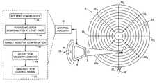
- FIG. 1Ashows a disk drive according to an embodiment of the present invention comprising a disk, an actuator arm, a head connected to a distal end of the actuator arm, and a voice coil motor (VCM).
- VCMvoice coil motor
- FIG. 1Bshows the format of an example servo sector for servoing the head over the disk.
- FIG. 1Cis a flow diagram according to an embodiment of the present invention wherein an inductor compensation circuit is toggled at least once before it is fully enabled.
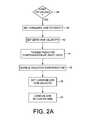
- FIG. 2Ashows a flow diagram according to an embodiment of the present invention wherein the inductor compensation circuit is toggled prior to one of a load or unload operation.
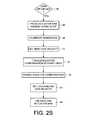
- FIG. 2Bshows a flow diagram according to an embodiment of the present invention wherein the actuator arm is pressed against a crash stop to calibrate an estimated voice coil resistance.
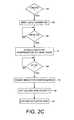
- FIG. 2Cshows a flow diagram according to an embodiment of the present invention wherein the inductor compensation circuit is toggled at the end of a seek operation prior to unloading the actuator arm.
- FIG. 3shows a flow diagram according to an embodiment of the present invention wherein the inductor compensation circuit is toggled for an on-time and then an off-time at least once.
- FIG. 4Aillustrates an example spike in the VCM current that causes acoustic noise when the inductor compensation circuit is not toggled.
- FIG. 4Billustrates an example of how the spike in the VCM current may be reduced by toggling the inductor compensation circuit.
- FIG. 4Cshows an embodiment of the present invention wherein at least one of an on-time, off-time, and number of cycles is adjusted to tune the toggling of the inductor compensation circuit.
- FIG. 5shows control circuitry according to an embodiment of the present invention wherein the inductor compensation circuit comprises a capacitor.
- FIG. 6shows control circuitry according to an embodiment of the present invention including a comparator for calibrating the toggling of the inductor compensation circuit.
- FIG. 1Ashows a disk drive according to an embodiment of the present invention comprising a disk 2 , a head 4 coupled to a distal end of an actuator arm 6 , and a voice coil motor (VCM) operable to rotate the actuator arm 6 about a pivot to actuate the head 4 radially over the disk 2 .
- the VCMcomprises a voice coil 8 coupled to a base of the actuator arm 6 and at least one permanent magnet (not shown).
- the disk drivefurther comprises control circuitry 10 comprising an inductor compensation circuit operable to generate an estimated inductance voltage of the voice coil 8 .
- FIG. 1Cshows a flow diagram executed by the control circuitry 10 wherein a velocity command of the VCM is set to substantially zero (step 12 ).
- the inductor compensation circuitis toggled at least once by enabling and disabling the inductor compensation circuit (step 14 ).
- the inductor compensation circuitis enabled (step 16 ), and the velocity command of the VCM is adjusted (step 18 ).
- a control signalis generated and applied to the voice coil 8 in order to move the actuator arm (step 20 ), wherein the control signal is generated in response to the adjusted velocity command, the voice coil voltage, and the estimated inductance voltage.
- the disk 2comprises a plurality of embedded servo sectors 22 0 - 22 N that define a plurality of concentric data tracks 23 , wherein each servo sector comprises a preamble 24 for storing a periodic pattern, which allows proper gain adjustment and timing synchronization of the read signal, and a sync mark 26 for storing a special pattern used to symbol synchronize to a servo data field 28 .
- the servo data field 28stores coarse head positioning information, such as a track address, used to position the head over a target data track during a seek operation.
- Each servo sector 22further comprises groups of servo bursts 30 (e.g., A, B, C and D bursts), which comprise a number of consecutive transitions recorded at precise intervals and offsets with respect to a data track centerline.
- the groups of servo bursts 30provide fine head position information used for centerline tracking while accessing a data track during write/read operations.
- the actuator arm 6is parked on a ramp 32 while the disk drive is powered down or idle. In one embodiment, prior to loading the actuator arm 6 onto the disk 2 , the actuator arm 6 is pressed against a crash stop 34 (rotated until a tang 36 contacts the crash stop 34 ) in order to calibrate a resistance of the voice coil 8 .
- FIG. 2Ais a flow diagram according to an embodiment of the present invention wherein during a load or unload operation (step 38 ) the VCM velocity command is set to a non-zero value (step 40 ) in order to charge the voice coil 8 with current.
- the VCM velocity commandis set to zero (step 12 ) and the inductor compensation circuit is toggled at least once (step 14 ) in order to precharge the inductor compensation circuit without generating an acoustic current spike.
- the inductor compensation circuitis enabled (step 16 ), the VCM velocity command is set to a value for loading or unloading the actuator arm 6 (step 42 ), and the actuator arm is loaded or unloaded (step 44 ).
- FIG. 2Bis a flow diagram according to an embodiment of the present invention wherein prior to performing a load or unload operation, a resistance of the voice coil 8 is calibrated so that a resistance voltage can be estimated and used in generating the VCM control signal.
- the actuator arm 6is pressed against a crash stop (step 46 ) and the resistance calibrated (step 48 ) by measuring the voice coil voltage and the voice coil current.
- the velocity of the voice coil 8is zero so that the main component of the voice coil voltage is due to the voice coil resistance.
- the voice coil resistanceAfter the voice coil resistance has been calibrated, it is used in generating the VCM control signal to load/unload the actuator arm by subtracting the estimated resistance voltage from the measured voice coil voltage.
- the VCM velocity commandis set to zero (step 12 ) and the inductor compensation circuit is toggled (step 14 ). In this manner, the inductor compensation circuit is precharged at a rate which helps minimize acoustic noise.
- the inductor compensation circuitis fully enabled (step 16 ), it will have been pre-charged with current which reduces the current spike and acoustic noise that would otherwise occur.
- FIG. 2Cis a flow diagram according to another embodiment of the present invention wherein during an unload operation (step 38 ), the control circuitry 10 first seeks the head 4 toward an outer diameter of the disk 2 in response to the embedded servo sectors 22 0 - 22 N (step 50 ). When the head 4 nears an outer diameter track near the end of the seek operation (step 52 ), the inductor compensation circuit is toggled (step 14 ) in order to precharge the inductor compensation circuit.
- the inductor compensation circuitWhen the head 4 reaches the target outer diameter track at the end of the seek operation (step 54 ) the inductor compensation circuit is fully enabled (step 16 ), the VCM velocity command is set to unload the actuator arm 6 (step 42 ), and the actuator arm 6 is unloaded in response to the VCM control signal (step 44 ).
- control circuitry 10presses the actuator arm 6 against an inner diameter crash stop in order to calibrate the voice coil resistance, and then moves the head 4 toward the outer diameter of the disk 2 , for example, by seeking the head 4 in response to the embedded servo sectors 22 0 - 22 N , or by moving the head 4 open loop in a velocity control mode described below.
- the control circuitry 10toggles the inductor compensation circuit after pressing the actuator arm 6 against the inner diameter crash stop.
- control circuitry 10estimates the voice coil resistance as a function of an estimated voice coil temperature, thereby avoiding the step of pressing the actuator arm 6 against the inner diameter crash stop so that instead the control circuitry 10 can immediately move the head 4 to the outer diameter of the disk 2 .
- FIG. 3is a flow diagram according to an embodiment of the present invention for loading/unloading the actuator arm 6 (step 38 ).
- a counter iis initialized to zero (step 56 ).
- the inductor compensation circuitis then enabled (step 58 ) for an on-time (step 60 ), and then disabled (step 62 ) for an off-time (step 64 ).
- the counter iis incremented (step 66 ) and the process is repeated until the counter i equals a threshold (step 68 ). In this manner, the inductor compensation circuit is toggled a number of cycles, wherein each cycle comprises an on-time and an off-time.
- FIG. 4Aillustrates an example spike in the VCM current that causes acoustic noise when the inductor compensation circuit is not toggled.
- the inductor compensation circuitis fully enabled after pressing the actuator arm 6 against the crash stop.
- the rapid initialization of the inductor compensation circuitcauses the loop to create a current spike and associated acoustic noise as illustrated in FIG. 4A .
- FIG. 4Billustrates an example of the reduction in the current spike and associated acoustic noise when the inductor compensation circuit is toggled according to an embodiment of the present invention.
- FIG. 4Cillustrates an embodiment of the present invention wherein toggling the inductor compensation circuit comprises enabling the inductor compensation circuit for an on-time, and disabling the inductor compensation circuit for an off-time, wherein the on/off periods are repeated for a number of cycles.
- at least one of the parameters shown in FIG. 4Care adjusted in order to calibrate the toggle operation. For example, in one embodiment at least one of the parameters of FIG. 4C is adjusted until the voice coil current remains below a threshold Th as illustrated in FIGS. 4A and 4B .
- the toggle parametersmay be calibrated once for a family of disk drives, and in another embodiment, the toggle parameters may be calibrated for each individual disk drive. In one embodiment, the toggle parameters may be calibrated during a manufacturing process of the disk drive, and in another embodiment, the toggle parameters are calibrated while the disk drive is deployed in the field.
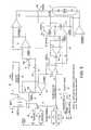
- FIG. 5shows example control circuitry 10 according to an embodiment of the present invention which operates in a normal operating mode wherein the voice coil 8 is driven by a current controlled feedback loop (e.g., when controlling the VCM in response to the embedded servo sectors 22 0 - 22 N ), and in a velocity control mode wherein the voice coil 8 is driven by a voltage controlled feedback loop (e.g., when loading or unloading the actuator arm 6 ).
- a current controlled feedback loope.g., when controlling the VCM in response to the embedded servo sectors 22 0 - 22 N
- a voltage controlled feedback loope.g., when loading or unloading the actuator arm 6 .
- switch 70 AWhen in the normal operating mode, switch 70 A is opened and switch 70 B is closed to configure the current feedback loop, and when in the velocity control mode, switch 70 A is closed and switch 70 B is opened to configure the voltage feedback loop.
- a velocity mode control signal 72configures the switches 70 A and 70 B for velocity control mode when the embedded servo sectors
- a velocity bit 74is set by the control circuitry 10 to activate the velocity mode control signal 72 via OR gate 76 .
- the velocity bit 74may be set during controlled modes of operation, such as during a powered load/unload operation, or when synchronization to the embedded servo data is lost.
- the velocity mode control signal 72may also be activated via AND gate 78 and OR gate 76 during emergency unloads, such as during power down or power failure. If the OE UNLOAD signal 80 has been preset to configure the drive for velocity mode unload, when a power down or power failure is detected, the control signals OUTPUT ENABLE (OE) 82 and TPARK1 84 are automatically activated, thereby activating the velocity mode control signal 72 .
- a digital-to-analog converter (DAC) 86generates an analog VCM command signal 88 in response to a digital command input signal 90 .
- a digital register 92is programmed with an operating command input during normal operation (including a powered load/unload), and a digital register 94 is programmed with a velocity mode command input used during emergency unloads, such as during power down or power failure.
- a digital register 96stores a calibrated voice coil resistance R value 98 for use during velocity control mode when the velocity bit 74 is activated (e.g., when calibrating a detected IR voltage 100 ).
- a digital register 102stores the calibrated voice coil resistance R value 98 for use during powered unloads, as well as emergency unloads during power down or power failure.
- the calibrated voice coil resistance R value 98is used to program a variable resistor 104 in order to calibrate the detected IR voltage 100 .
- U.S. Pat. No. 6,690,536“DISK DRIVE EMPLOYING VCM DEMAND CURRENT TO CALIBRATE VCM IR VOLTAGE FOR VELOCITY CONTROL OF AN ACTUATOR ARM”
- U.S. Pat. No. 6,795,268“DISK DRIVE EMPLOYING SEEK TIME VCM IR VOLTAGE CALIBRATION FOR VELOCITY CONTROL OF AN ACTUATOR ARM” the disclosures of which are incorporated herein by reference.
- a sense resistor 106 and amplifier 108implement a suitable current detector for generating a voltage representing the current 110 flowing through the voice coil 8 .
- the output of amplifier 112is the calibrated IR voltage 100 .
- An amplifier 114measures the voltage 116 across the voice coil 8 .
- the IR voltage 100is subtracted from the voice coil voltage 116 and amplified at amplifier 118 , the output 120 of which is filtered by amplifier 122 and capacitor 124 and summed with the feedback current 110 through capacitor 125 in order to subtract the voice coil inductance voltage, thereby generating a velocity feedback voltage 126 representing the velocity of the VCM (the BEMF voltage).
- the velocity feedback voltage 126is subtracted from the VCM command signal 88 to generate the control signal 128 applied to the voice coil 8 .
- the inductor compensation circuitis toggled (step 14 of FIG. 1C ) by toggling switch 130 . That is, switch 130 is turned on for an on-time and turned off for an off-time for at least one cycle, and in one embodiment over multiple cycles as shown in FIG. 4C .
- the inductor compensation circuitis then fully enabled (step 16 of FIG. 1C ) by turning switch 130 on and keeping switch 130 on during the velocity mode operation (e.g., during a load or unload operation).
- the control circuitry 10seeks the head 4 to an outer diameter track (e.g., near the bottom of the ramp 32 ) by programming register 92 with appropriate command values in response to the embedded servo sectors 22 0 - 22 N .
- the command valuemay be generated as a velocity error relative to the radial position of the head 4 (i.e., relative to a seek profile).
- the seek operation to the outer diameter trackterminates with the velocity of the head 4 approximately zero after settling onto the target track (after toggling the inductor compensation circuit). Thereafter the control circuitry 10 enables the inductor compensation circuit and asserts the velocity bit 74 to configure the circuitry of FIG. 5 into the velocity mode, and then programs register 92 with ramped command values so that the actuator arm 6 contacts the ramp 32 at a low velocity and then increases velocity as the actuator arm 6 travels up and along the ramp 32 .
- FIG. 6shows control circuitry 10 according to an embodiment of the present invention including a comparator 132 which compares the estimated current 110 flowing through the voice coil 8 to a threshold Th in order to calibrate the toggle parameters (e.g., on-time, off-time, and/or number of cycles).
- the toggle parametersare calibrated by performing multiple velocity mode operations (e.g., multiple loads and/or unloads) and adjusting the toggle parameters prior to each operation until the peak current falls below the threshold in comparator 132 .
- one or more of the toggling parametersare adjusted in real time in response to the voice coil current. For example, the on-time of multiple toggle cycles may be decreased until the voice coil current falls below the threshold at comparator 132 .
- the inductor compensation circuitmay be used during any suitable velocity mode operation in addition to, or instead of a load or unload operation, such as when the control circuitry 10 loses synchronization to the embedded servo sectors 22 0 - 22 N .
- the inductor compensation circuitmay comprise any suitable circuitry other than the circuitry shown in FIG. 5 .
- control circuitrymay also be employed to implement the flow diagrams in the embodiments of the present invention, such as any suitable integrated circuit or circuits.
- the control circuitrymay be implemented within a read channel integrated circuit, or in a component separate from the read channel, such as a disk controller, or certain steps described above may be performed by a read channel and others by a disk controller.
- the read channel and disk controllerare implemented as separate integrated circuits, and in an alternative embodiment they are fabricated into a single integrated circuit or system on a chip (SOC).
- the control circuitrymay include a suitable preamp circuit implemented as a separate integrated circuit, integrated into the read channel or disk controller circuit, or integrated into an SOC.
- control circuitrycomprises a microprocessor executing instructions, the instructions being operable to cause the microprocessor to perform the steps of the flow diagrams described herein.
- the instructionsmay be stored in any computer-readable medium. In one embodiment, they may be stored on a non-volatile semiconductor memory external to the microprocessor, or integrated with the microprocessor in a SOC. In another embodiment, the instructions are stored on the disk and read into a volatile semiconductor memory when the disk drive is powered on. In yet another embodiment, the control circuitry comprises suitable logic circuitry, such as state machine circuitry.
Landscapes
- Moving Of Head For Track Selection And Changing (AREA)
- Control Of Linear Motors (AREA)
Abstract
Description
Claims (25)
Priority Applications (1)
| Application Number | Priority Date | Filing Date | Title |
|---|---|---|---|
| US12/126,377US8988811B1 (en) | 2008-05-23 | 2008-05-23 | Disk drive toggling VCM inductor compensation to reduce acoustic noise |
Applications Claiming Priority (1)
| Application Number | Priority Date | Filing Date | Title |
|---|---|---|---|
| US12/126,377US8988811B1 (en) | 2008-05-23 | 2008-05-23 | Disk drive toggling VCM inductor compensation to reduce acoustic noise |
Publications (1)
| Publication Number | Publication Date |
|---|---|
| US8988811B1true US8988811B1 (en) | 2015-03-24 |
Family
ID=52683338
Family Applications (1)
| Application Number | Title | Priority Date | Filing Date |
|---|---|---|---|
| US12/126,377Active2029-09-22US8988811B1 (en) | 2008-05-23 | 2008-05-23 | Disk drive toggling VCM inductor compensation to reduce acoustic noise |
Country Status (1)
| Country | Link |
|---|---|
| US (1) | US8988811B1 (en) |
Cited By (2)
| Publication number | Priority date | Publication date | Assignee | Title |
|---|---|---|---|---|
| US20140117903A1 (en)* | 2012-10-25 | 2014-05-01 | Texas Instruments Incorporated | Back emf monitor for motor control |
| US11790947B1 (en)* | 2022-05-03 | 2023-10-17 | Seagate Technology Llc | Idle power saving for actuator device |
Citations (36)
| Publication number | Priority date | Publication date | Assignee | Title |
|---|---|---|---|---|
| US5654840A (en)* | 1994-06-30 | 1997-08-05 | Western Digital Corporation | Hard disk drive which uses the back EMF of the actuator to detect shocks |
| US5696647A (en) | 1994-03-28 | 1997-12-09 | Seagate Technology, Inc. | Method for carrying out seeks in a hard disc drive to limit the generation of acoustic noise including using a slew rate limit |
| US5768045A (en) | 1995-12-20 | 1998-06-16 | Western Digital Corporation | Hardware velocity limit control system |
| US5936788A (en) | 1994-06-02 | 1999-08-10 | International Business Machines Corporation | Method and apparatus for ramp load and unload |
| US6025968A (en) | 1997-06-23 | 2000-02-15 | International Business Machines Corporation | Load/unload disk drive with multistage retract circuit for parking the head carriers on power down |
| US6097564A (en) | 1996-06-05 | 2000-08-01 | Mobile Storage Technology Inc. | Method for precise velocity feedback control in an actuator system of a disk drive |
| US6148240A (en) | 1998-03-06 | 2000-11-14 | Quantum Corporation | Method and apparatus for performing an open-loop current shaping for seeking acoustics reduction in a disk drive |
| US6256163B1 (en) | 1998-03-06 | 2001-07-03 | Quantum Corporation | Method and apparatus for performing current shaping for seeking acoustics reduction in a disk drive |
| US20010019463A1 (en) | 1997-11-14 | 2001-09-06 | Castlewood Systems, Inc. | Head loading and unloading method and device |
| US6316898B1 (en) | 1999-10-29 | 2001-11-13 | International Business Machines Corporation | Pulse modulated capacitive retract device for a voice coil actuator |
| US6396652B1 (en) | 1998-08-12 | 2002-05-28 | Kabushiki Kaisha Toshiba | Apparatus and method for control head unloading on power down in a disk drive |
| US6560057B1 (en)* | 1999-04-30 | 2003-05-06 | International Business Machines Corporation | Head positioning system for a disk drive during a power down condition |
| US20030161065A1 (en) | 2002-01-30 | 2003-08-28 | Masahide Yatsu | Method and apparatus for controlling the actuator of the head-positioning system provided in a disk drive |
| US6690536B1 (en) | 2000-10-31 | 2004-02-10 | Western Digital Technologies, Inc. | Disk drive employing VCM demand current to calibrate VCM IR voltage for velocity control of an actuator arm |
| US6717765B2 (en) | 2001-06-22 | 2004-04-06 | Iomega Corporation | Method and circuit for sensing back EMF |
| US6795268B1 (en) | 2000-10-31 | 2004-09-21 | Western Digital Technologies, Inc. | Disk drive employing seek time vcm ir voltage calibration for velocity control of an actuator arm |
| US6826007B1 (en) | 2002-08-30 | 2004-11-30 | Western Digital Technologies, Inc. | Disk drive using dual slope integrator to extract velocity of an actuator arm from a back EMF voltage |
| US20050007688A1 (en) | 2003-07-09 | 2005-01-13 | Joseph Chang | Dual speed control to reduce audible noise and protect head during unload in ramp load drives with pawl latch |
| US6900959B1 (en)* | 2003-03-31 | 2005-05-31 | Western Digital Technologies, Inc. | Disk drive comprising an offset-nulling amplifier for detecting a back EMF voltage of a voice coil motor |
| US6937429B2 (en) | 2001-05-23 | 2005-08-30 | Hitachi Ulsi Systems Co., Ltd. | Magnetic disk storage apparatus and method for controlling magnetic disk storage apparatus |
| US6950271B2 (en)* | 2002-09-27 | 2005-09-27 | Matsushita Electric Industrial Co., Ltd. | Disk drive and disk drive control method |
| US6950272B1 (en) | 2000-06-09 | 2005-09-27 | Maxtor Corporation | Method and apparatus for the acoustic improvement of the pulsed current method for controlling the velocity of a transducer head |
| US6950274B2 (en)* | 2001-11-28 | 2005-09-27 | Matsushita Electric Industrial Co., Ltd. | Disk storage apparatus and disk storage apparatus control method |
| US6954324B1 (en) | 2003-11-26 | 2005-10-11 | Western Digital Technologies, Inc. | Disk drive disabling BEMF detection window to reduce acoustic noise while using wedge spindle speed control |
| US6982848B2 (en)* | 2003-05-30 | 2006-01-03 | Matsushita Electric Industrial Co., Ltd. | Disk apparatus and head positioning method |
| US7042673B2 (en)* | 2003-12-12 | 2006-05-09 | Samsung Electronics Co., Ltd. | Hard disk drive calibration method and apparatus |
| US7054098B1 (en) | 2004-06-01 | 2006-05-30 | Western Digital Technologies, Inc. | Disk drive employing asymmetric acceleration/deceleration pulses for acoustic noise reduction during unlatch |
| US7064919B2 (en)* | 2000-07-19 | 2006-06-20 | Matsushita Electric Industrial Co., Ltd. | Disk storage apparatus |
| US7072135B2 (en) | 2002-11-12 | 2006-07-04 | Fujitsu Limited | Disk apparatus, head retracting method and head actuator control circuit |
| US7082010B1 (en) | 2001-11-09 | 2006-07-25 | Maxtor Corporation | Method and apparatus for reducing seek acoustics in a disk drive using feedback during large current transitions |
| US7095579B1 (en) | 2005-06-02 | 2006-08-22 | Western Digital Technologies, Inc. | Disk drive employing momentum based unload during power failure |
| US7110207B2 (en) | 2001-04-23 | 2006-09-19 | Fujitsu Limited | Load/unload operation control method and storage apparatus |
| US7224546B1 (en) | 2004-01-31 | 2007-05-29 | Western Digital Technologies, Inc. | Disk drive employing a calibrated brake pulse to reduce acoustic noise when latching an actuator arm |
| US20070285828A1 (en) | 2006-06-07 | 2007-12-13 | Texas Instruments Incorporated | Low-Power Pulse-Width-Modulated Retract of Disk Drive Actuator |
| US7477471B1 (en)* | 2007-04-20 | 2009-01-13 | Western Digital Technologies, Inc. | Disk drive employing offset compensation for velocity control of a voice coil motor |
| US7576939B2 (en)* | 2007-11-15 | 2009-08-18 | Seagate Technology Llc | Discontinuous mode back EMF measurement |
- 2008
- 2008-05-23USUS12/126,377patent/US8988811B1/enactiveActive
Patent Citations (37)
| Publication number | Priority date | Publication date | Assignee | Title |
|---|---|---|---|---|
| US5696647A (en) | 1994-03-28 | 1997-12-09 | Seagate Technology, Inc. | Method for carrying out seeks in a hard disc drive to limit the generation of acoustic noise including using a slew rate limit |
| US5751513A (en) | 1994-03-28 | 1998-05-12 | Seagate Technology, Inc. | Method for carrying out seeks in a hard disc drive to limit the generation of acoustic noise |
| US5936788A (en) | 1994-06-02 | 1999-08-10 | International Business Machines Corporation | Method and apparatus for ramp load and unload |
| US5654840A (en)* | 1994-06-30 | 1997-08-05 | Western Digital Corporation | Hard disk drive which uses the back EMF of the actuator to detect shocks |
| US5768045A (en) | 1995-12-20 | 1998-06-16 | Western Digital Corporation | Hardware velocity limit control system |
| US6097564A (en) | 1996-06-05 | 2000-08-01 | Mobile Storage Technology Inc. | Method for precise velocity feedback control in an actuator system of a disk drive |
| US6025968A (en) | 1997-06-23 | 2000-02-15 | International Business Machines Corporation | Load/unload disk drive with multistage retract circuit for parking the head carriers on power down |
| US20010019463A1 (en) | 1997-11-14 | 2001-09-06 | Castlewood Systems, Inc. | Head loading and unloading method and device |
| US6148240A (en) | 1998-03-06 | 2000-11-14 | Quantum Corporation | Method and apparatus for performing an open-loop current shaping for seeking acoustics reduction in a disk drive |
| US6256163B1 (en) | 1998-03-06 | 2001-07-03 | Quantum Corporation | Method and apparatus for performing current shaping for seeking acoustics reduction in a disk drive |
| US6396652B1 (en) | 1998-08-12 | 2002-05-28 | Kabushiki Kaisha Toshiba | Apparatus and method for control head unloading on power down in a disk drive |
| US6560057B1 (en)* | 1999-04-30 | 2003-05-06 | International Business Machines Corporation | Head positioning system for a disk drive during a power down condition |
| US6316898B1 (en) | 1999-10-29 | 2001-11-13 | International Business Machines Corporation | Pulse modulated capacitive retract device for a voice coil actuator |
| US6950272B1 (en) | 2000-06-09 | 2005-09-27 | Maxtor Corporation | Method and apparatus for the acoustic improvement of the pulsed current method for controlling the velocity of a transducer head |
| US7064919B2 (en)* | 2000-07-19 | 2006-06-20 | Matsushita Electric Industrial Co., Ltd. | Disk storage apparatus |
| US6690536B1 (en) | 2000-10-31 | 2004-02-10 | Western Digital Technologies, Inc. | Disk drive employing VCM demand current to calibrate VCM IR voltage for velocity control of an actuator arm |
| US6795268B1 (en) | 2000-10-31 | 2004-09-21 | Western Digital Technologies, Inc. | Disk drive employing seek time vcm ir voltage calibration for velocity control of an actuator arm |
| US7110207B2 (en) | 2001-04-23 | 2006-09-19 | Fujitsu Limited | Load/unload operation control method and storage apparatus |
| US6937429B2 (en) | 2001-05-23 | 2005-08-30 | Hitachi Ulsi Systems Co., Ltd. | Magnetic disk storage apparatus and method for controlling magnetic disk storage apparatus |
| US6717765B2 (en) | 2001-06-22 | 2004-04-06 | Iomega Corporation | Method and circuit for sensing back EMF |
| US7082010B1 (en) | 2001-11-09 | 2006-07-25 | Maxtor Corporation | Method and apparatus for reducing seek acoustics in a disk drive using feedback during large current transitions |
| US6950274B2 (en)* | 2001-11-28 | 2005-09-27 | Matsushita Electric Industrial Co., Ltd. | Disk storage apparatus and disk storage apparatus control method |
| US20030161065A1 (en) | 2002-01-30 | 2003-08-28 | Masahide Yatsu | Method and apparatus for controlling the actuator of the head-positioning system provided in a disk drive |
| US6826007B1 (en) | 2002-08-30 | 2004-11-30 | Western Digital Technologies, Inc. | Disk drive using dual slope integrator to extract velocity of an actuator arm from a back EMF voltage |
| US6950271B2 (en)* | 2002-09-27 | 2005-09-27 | Matsushita Electric Industrial Co., Ltd. | Disk drive and disk drive control method |
| US7072135B2 (en) | 2002-11-12 | 2006-07-04 | Fujitsu Limited | Disk apparatus, head retracting method and head actuator control circuit |
| US6900959B1 (en)* | 2003-03-31 | 2005-05-31 | Western Digital Technologies, Inc. | Disk drive comprising an offset-nulling amplifier for detecting a back EMF voltage of a voice coil motor |
| US6982848B2 (en)* | 2003-05-30 | 2006-01-03 | Matsushita Electric Industrial Co., Ltd. | Disk apparatus and head positioning method |
| US20050007688A1 (en) | 2003-07-09 | 2005-01-13 | Joseph Chang | Dual speed control to reduce audible noise and protect head during unload in ramp load drives with pawl latch |
| US6954324B1 (en) | 2003-11-26 | 2005-10-11 | Western Digital Technologies, Inc. | Disk drive disabling BEMF detection window to reduce acoustic noise while using wedge spindle speed control |
| US7042673B2 (en)* | 2003-12-12 | 2006-05-09 | Samsung Electronics Co., Ltd. | Hard disk drive calibration method and apparatus |
| US7224546B1 (en) | 2004-01-31 | 2007-05-29 | Western Digital Technologies, Inc. | Disk drive employing a calibrated brake pulse to reduce acoustic noise when latching an actuator arm |
| US7054098B1 (en) | 2004-06-01 | 2006-05-30 | Western Digital Technologies, Inc. | Disk drive employing asymmetric acceleration/deceleration pulses for acoustic noise reduction during unlatch |
| US7095579B1 (en) | 2005-06-02 | 2006-08-22 | Western Digital Technologies, Inc. | Disk drive employing momentum based unload during power failure |
| US20070285828A1 (en) | 2006-06-07 | 2007-12-13 | Texas Instruments Incorporated | Low-Power Pulse-Width-Modulated Retract of Disk Drive Actuator |
| US7477471B1 (en)* | 2007-04-20 | 2009-01-13 | Western Digital Technologies, Inc. | Disk drive employing offset compensation for velocity control of a voice coil motor |
| US7576939B2 (en)* | 2007-11-15 | 2009-08-18 | Seagate Technology Llc | Discontinuous mode back EMF measurement |
Cited By (5)
| Publication number | Priority date | Publication date | Assignee | Title |
|---|---|---|---|---|
| US20140117903A1 (en)* | 2012-10-25 | 2014-05-01 | Texas Instruments Incorporated | Back emf monitor for motor control |
| US9136787B2 (en)* | 2012-10-25 | 2015-09-15 | Texas Instruments Incorporated | Back EMF monitor for motor control |
| US20170117835A1 (en)* | 2012-10-25 | 2017-04-27 | Texas Instruments Incorporated | Back EMF Monitor for Motor Control |
| US10211767B2 (en)* | 2012-10-25 | 2019-02-19 | Texas Instruments Incorporated | Back EMF monitor for motor control |
| US11790947B1 (en)* | 2022-05-03 | 2023-10-17 | Seagate Technology Llc | Idle power saving for actuator device |
Similar Documents
| Publication | Publication Date | Title |
|---|---|---|
| US7876522B1 (en) | Disk drive updating estimate of voice coil resistance to account for resistance change prior to unload operation | |
| US6690536B1 (en) | Disk drive employing VCM demand current to calibrate VCM IR voltage for velocity control of an actuator arm | |
| US6795268B1 (en) | Disk drive employing seek time vcm ir voltage calibration for velocity control of an actuator arm | |
| US7477471B1 (en) | Disk drive employing offset compensation for velocity control of a voice coil motor | |
| US7573670B1 (en) | Disk drive seeking to OD track and then ramping velocity to implement fast unload | |
| US6900959B1 (en) | Disk drive comprising an offset-nulling amplifier for detecting a back EMF voltage of a voice coil motor | |
| US6867944B1 (en) | Disk drive comprising VCM stall detector for velocity control of an actuator arm | |
| US8611040B1 (en) | Disk drive adjusting microactuator gain by injecting a sinusoid into a servo control system | |
| US7800857B1 (en) | Disk drive calibrating voice coil resistance for velocity control of voice coil motor | |
| US7839600B1 (en) | Disk drive employing data-based basis function expansion for tuning seek servo loop | |
| US7760458B1 (en) | Disk drive adjusting head bias during servo synchronization to compensate for over/under sensitivity | |
| US8649121B1 (en) | Disk drive tuning speed control loop for a spindle motor | |
| US8072703B1 (en) | Disk drive detecting when head is parked on ramp | |
| US6826007B1 (en) | Disk drive using dual slope integrator to extract velocity of an actuator arm from a back EMF voltage | |
| US8773807B1 (en) | Disk drive calibrating fly height during startup by reading spacing pattern in servo sectors | |
| US8564899B2 (en) | Disk drive decreasing a settle delay based on speed that a settle parameter adapts | |
| US5768045A (en) | Hardware velocity limit control system | |
| US8786976B1 (en) | Disk drive detecting when head is on ramp | |
| US10714133B1 (en) | Data storage device capable of overriding a servo command to avoid an overcurrent condition | |
| JP2000163901A (en) | Speed correction value calibration method applied to head load / unload type disk device | |
| US6760178B2 (en) | Disk memory apparatus compensating for temperature in a circuit for monitoring the back electromotive force of a voice coil motor, and method for controlling of a disk memory apparatus | |
| US20030161065A1 (en) | Method and apparatus for controlling the actuator of the head-positioning system provided in a disk drive | |
| US7558017B2 (en) | Magnetic disk drive and a loading/unloading method | |
| US7277251B2 (en) | Data reliability improvement at low temperature | |
| US8922939B1 (en) | Disk drive generating feed-forward fly height control based on temperature sensitive fly height sensor |
Legal Events
| Date | Code | Title | Description |
|---|---|---|---|
| AS | Assignment | Owner name:WESTERN DIGITAL TECHNOLOGIES, INC., CALIFORNIA Free format text:ASSIGNMENT OF ASSIGNORS INTEREST;ASSIGNORS:DING, JIANGHONG;PHAN, DUC T.;RYAN, ROBERT P.;SIGNING DATES FROM 20080610 TO 20080617;REEL/FRAME:021336/0977 | |
| STCF | Information on status: patent grant | Free format text:PATENTED CASE | |
| AS | Assignment | Owner name:JPMORGAN CHASE BANK, N.A., AS COLLATERAL AGENT, ILLINOIS Free format text:SECURITY AGREEMENT;ASSIGNOR:WESTERN DIGITAL TECHNOLOGIES, INC.;REEL/FRAME:038722/0229 Effective date:20160512 Owner name:U.S. BANK NATIONAL ASSOCIATION, AS COLLATERAL AGENT, CALIFORNIA Free format text:SECURITY AGREEMENT;ASSIGNOR:WESTERN DIGITAL TECHNOLOGIES, INC.;REEL/FRAME:038744/0281 Effective date:20160512 Owner name:JPMORGAN CHASE BANK, N.A., AS COLLATERAL AGENT, ILLINOIS Free format text:SECURITY AGREEMENT;ASSIGNOR:WESTERN DIGITAL TECHNOLOGIES, INC.;REEL/FRAME:038744/0481 Effective date:20160512 Owner name:JPMORGAN CHASE BANK, N.A., AS COLLATERAL AGENT, IL Free format text:SECURITY AGREEMENT;ASSIGNOR:WESTERN DIGITAL TECHNOLOGIES, INC.;REEL/FRAME:038722/0229 Effective date:20160512 Owner name:U.S. BANK NATIONAL ASSOCIATION, AS COLLATERAL AGEN Free format text:SECURITY AGREEMENT;ASSIGNOR:WESTERN DIGITAL TECHNOLOGIES, INC.;REEL/FRAME:038744/0281 Effective date:20160512 Owner name:JPMORGAN CHASE BANK, N.A., AS COLLATERAL AGENT, IL Free format text:SECURITY AGREEMENT;ASSIGNOR:WESTERN DIGITAL TECHNOLOGIES, INC.;REEL/FRAME:038744/0481 Effective date:20160512 | |
| AS | Assignment | Owner name:WESTERN DIGITAL TECHNOLOGIES, INC., CALIFORNIA Free format text:RELEASE BY SECURED PARTY;ASSIGNOR:U.S. BANK NATIONAL ASSOCIATION, AS COLLATERAL AGENT;REEL/FRAME:045501/0714 Effective date:20180227 | |
| MAFP | Maintenance fee payment | Free format text:PAYMENT OF MAINTENANCE FEE, 4TH YEAR, LARGE ENTITY (ORIGINAL EVENT CODE: M1551); ENTITY STATUS OF PATENT OWNER: LARGE ENTITY Year of fee payment:4 | |
| AS | Assignment | Owner name:WESTERN DIGITAL TECHNOLOGIES, INC., CALIFORNIA Free format text:RELEASE OF SECURITY INTEREST AT REEL 038744 FRAME 0481;ASSIGNOR:JPMORGAN CHASE BANK, N.A.;REEL/FRAME:058982/0556 Effective date:20220203 | |
| MAFP | Maintenance fee payment | Free format text:PAYMENT OF MAINTENANCE FEE, 8TH YEAR, LARGE ENTITY (ORIGINAL EVENT CODE: M1552); ENTITY STATUS OF PATENT OWNER: LARGE ENTITY Year of fee payment:8 | |
| AS | Assignment | Owner name:JPMORGAN CHASE BANK, N.A., ILLINOIS Free format text:PATENT COLLATERAL AGREEMENT - A&R LOAN AGREEMENT;ASSIGNOR:WESTERN DIGITAL TECHNOLOGIES, INC.;REEL/FRAME:064715/0001 Effective date:20230818 Owner name:JPMORGAN CHASE BANK, N.A., ILLINOIS Free format text:PATENT COLLATERAL AGREEMENT - DDTL LOAN AGREEMENT;ASSIGNOR:WESTERN DIGITAL TECHNOLOGIES, INC.;REEL/FRAME:067045/0156 Effective date:20230818 |