US8988399B2 - Vehicular interface including steering wheel control assembly - Google Patents
Vehicular interface including steering wheel control assemblyDownload PDFInfo
- Publication number
- US8988399B2 US8988399B2US11/426,979US42697906AUS8988399B2US 8988399 B2US8988399 B2US 8988399B2US 42697906 AUS42697906 AUS 42697906AUS 8988399 B2US8988399 B2US 8988399B2
- Authority
- US
- United States
- Prior art keywords
- rotary dial
- adjustable aspect
- steering wheel
- display
- option
- Prior art date
- Legal status (The legal status is an assumption and is not a legal conclusion. Google has not performed a legal analysis and makes no representation as to the accuracy of the status listed.)
- Active, expires
Links
Images


Classifications
- G—PHYSICS
- G06—COMPUTING OR CALCULATING; COUNTING
- G06F—ELECTRIC DIGITAL DATA PROCESSING
- G06F3/00—Input arrangements for transferring data to be processed into a form capable of being handled by the computer; Output arrangements for transferring data from processing unit to output unit, e.g. interface arrangements
- G06F3/01—Input arrangements or combined input and output arrangements for interaction between user and computer
- G06F3/048—Interaction techniques based on graphical user interfaces [GUI]
- G06F3/0484—Interaction techniques based on graphical user interfaces [GUI] for the control of specific functions or operations, e.g. selecting or manipulating an object, an image or a displayed text element, setting a parameter value or selecting a range
- G06F3/04847—Interaction techniques to control parameter settings, e.g. interaction with sliders or dials
- B—PERFORMING OPERATIONS; TRANSPORTING
- B60—VEHICLES IN GENERAL
- B60K—ARRANGEMENT OR MOUNTING OF PROPULSION UNITS OR OF TRANSMISSIONS IN VEHICLES; ARRANGEMENT OR MOUNTING OF PLURAL DIVERSE PRIME-MOVERS IN VEHICLES; AUXILIARY DRIVES FOR VEHICLES; INSTRUMENTATION OR DASHBOARDS FOR VEHICLES; ARRANGEMENTS IN CONNECTION WITH COOLING, AIR INTAKE, GAS EXHAUST OR FUEL SUPPLY OF PROPULSION UNITS IN VEHICLES
- B60K35/00—Instruments specially adapted for vehicles; Arrangement of instruments in or on vehicles
- B60K35/10—Input arrangements, i.e. from user to vehicle, associated with vehicle functions or specially adapted therefor
- B—PERFORMING OPERATIONS; TRANSPORTING
- B60—VEHICLES IN GENERAL
- B60K—ARRANGEMENT OR MOUNTING OF PROPULSION UNITS OR OF TRANSMISSIONS IN VEHICLES; ARRANGEMENT OR MOUNTING OF PLURAL DIVERSE PRIME-MOVERS IN VEHICLES; AUXILIARY DRIVES FOR VEHICLES; INSTRUMENTATION OR DASHBOARDS FOR VEHICLES; ARRANGEMENTS IN CONNECTION WITH COOLING, AIR INTAKE, GAS EXHAUST OR FUEL SUPPLY OF PROPULSION UNITS IN VEHICLES
- B60K35/00—Instruments specially adapted for vehicles; Arrangement of instruments in or on vehicles
- B60K35/20—Output arrangements, i.e. from vehicle to user, associated with vehicle functions or specially adapted therefor
- B60K35/21—Output arrangements, i.e. from vehicle to user, associated with vehicle functions or specially adapted therefor using visual output, e.g. blinking lights or matrix displays
- B60K35/22—Display screens
- B—PERFORMING OPERATIONS; TRANSPORTING
- B60—VEHICLES IN GENERAL
- B60K—ARRANGEMENT OR MOUNTING OF PROPULSION UNITS OR OF TRANSMISSIONS IN VEHICLES; ARRANGEMENT OR MOUNTING OF PLURAL DIVERSE PRIME-MOVERS IN VEHICLES; AUXILIARY DRIVES FOR VEHICLES; INSTRUMENTATION OR DASHBOARDS FOR VEHICLES; ARRANGEMENTS IN CONNECTION WITH COOLING, AIR INTAKE, GAS EXHAUST OR FUEL SUPPLY OF PROPULSION UNITS IN VEHICLES
- B60K35/00—Instruments specially adapted for vehicles; Arrangement of instruments in or on vehicles
- B60K35/50—Instruments characterised by their means of attachment to or integration in the vehicle
- B—PERFORMING OPERATIONS; TRANSPORTING
- B60—VEHICLES IN GENERAL
- B60K—ARRANGEMENT OR MOUNTING OF PROPULSION UNITS OR OF TRANSMISSIONS IN VEHICLES; ARRANGEMENT OR MOUNTING OF PLURAL DIVERSE PRIME-MOVERS IN VEHICLES; AUXILIARY DRIVES FOR VEHICLES; INSTRUMENTATION OR DASHBOARDS FOR VEHICLES; ARRANGEMENTS IN CONNECTION WITH COOLING, AIR INTAKE, GAS EXHAUST OR FUEL SUPPLY OF PROPULSION UNITS IN VEHICLES
- B60K35/00—Instruments specially adapted for vehicles; Arrangement of instruments in or on vehicles
- B60K35/60—Instruments characterised by their location or relative disposition in or on vehicles
- B60K37/06—
- G—PHYSICS
- G06—COMPUTING OR CALCULATING; COUNTING
- G06F—ELECTRIC DIGITAL DATA PROCESSING
- G06F3/00—Input arrangements for transferring data to be processed into a form capable of being handled by the computer; Output arrangements for transferring data from processing unit to output unit, e.g. interface arrangements
- G06F3/01—Input arrangements or combined input and output arrangements for interaction between user and computer
- G06F3/03—Arrangements for converting the position or the displacement of a member into a coded form
- G06F3/033—Pointing devices displaced or positioned by the user, e.g. mice, trackballs, pens or joysticks; Accessories therefor
- G06F3/0362—Pointing devices displaced or positioned by the user, e.g. mice, trackballs, pens or joysticks; Accessories therefor with detection of 1D translations or rotations of an operating part of the device, e.g. scroll wheels, sliders, knobs, rollers or belts
- B60K2350/928—
- B—PERFORMING OPERATIONS; TRANSPORTING
- B60—VEHICLES IN GENERAL
- B60K—ARRANGEMENT OR MOUNTING OF PROPULSION UNITS OR OF TRANSMISSIONS IN VEHICLES; ARRANGEMENT OR MOUNTING OF PLURAL DIVERSE PRIME-MOVERS IN VEHICLES; AUXILIARY DRIVES FOR VEHICLES; INSTRUMENTATION OR DASHBOARDS FOR VEHICLES; ARRANGEMENTS IN CONNECTION WITH COOLING, AIR INTAKE, GAS EXHAUST OR FUEL SUPPLY OF PROPULSION UNITS IN VEHICLES
- B60K2360/00—Indexing scheme associated with groups B60K35/00 or B60K37/00 relating to details of instruments or dashboards
- B60K2360/77—Instrument locations other than the dashboard
- B60K2360/782—Instrument locations other than the dashboard on the steering wheel
Definitions
- the present inventiongenerally relates to a steering wheel control assembly and, more particularly, to a vehicular interface utilizing a control assembly deployed on the steering wheel of a vehicle.
- Vehiclesare becoming increasingly equipped with a wide range of systems including features that may be adjusted by a user of the vehicle.
- a useri.e., a driver or passenger
- may be required to choose from multiple audio sourcese.g., CD, XM radio, FM radio, AM radio, onboard hard drive, an auxiliary source, etc.
- multiple audio sourcese.g., CD, XM radio, FM radio, AM radio, onboard hard drive, an auxiliary source, etc.
- features associated with the selected audio sourcee.g., tracks for a particular CD, stations for FM radio, audio files for the onboard hard drive, etc.
- the usermay be permitted to fine tune the audio system's tone balance (e.g., adjust the relative levels of bass, treble, mid-range tones, etc.), adjust the system's volume, and/or manipulate the appearance of the a display (e.g., time display for CD tracks, broadcast text display for radio, graphic equalizer display, backlight color, etc.).
- tone balancee.g., adjust the relative levels of bass, treble, mid-range tones, etc.
- the system's volumee.g., a display for CD tracks, broadcast text display for radio, graphic equalizer display, backlight color, etc.
- a Driver Information Centerincludes a plurality of buttons and a display (e.g., a liquid crystal display) capable of displaying several lines of characters.
- the DICis typically disposed on the vehicle's center stack located between the driver seat and the front passenger seat so that the controls may be accessed by either the driver or a front passenger of the vehicle.
- a usernavigates through a tiered hierarchy of menus to view and select amongst various vehicular systems and system features.
- Tiered menu structures of this typecan become relatively complex and often require that a user advance through several different levels of menus to locate a desired feature. Additionally, such menu structures may not permit the simultaneous display of multiple groups of system features.
- a user control assemblyfor use on a vehicle having a processor, a steering wheel, and a plurality of vehicular systems controllable by the processor each having first and second adjustable features.
- the user controlcomprises a first button mounted on the steering wheel and coupled to the processor for selecting one of the plurality of vehicular systems, and first and second rotary dials mounted on the steering wheel and coupled to the processor for adjusting the first and second adjustable features associated with the selected system.
- FIGS. 1 and 2are front and rear views of a user control deployed on the steering wheel of a vehicle in accordance with a first embodiment of the present invention
- FIG. 3is a functional side view of the user control shown in FIGS. 1 and 2 illustrating the ways in which the button and rotary dials of the user control may be actuated;
- FIG. 4is a block diagram of a user interface including the user control shown in FIGS. 1-3 , a first display, a second display, a sound generator, and a plurality of vehicular systems;
- FIGS. 5 and 6are block diagrams illustrating the relationship between first and second vehicular systems, respectively, and the features associated therewith as displayed by the user interface shown in FIG. 4 ;
- FIGS. 7-10illustrate one way in which the first display of the user interface shown in FIG. 4 may be configured to appear as a user adjusts features associated with a vehicle's audio system.
- FIGS. 1 and 2are front and rear views of a steering wheel control assembly deployed on a steering wheel 100 of a vehicle (not shown) in accordance with a first embodiment of the present invention.
- Steering wheel 100comprises a rim portion 102 coupled to a central portion 104 by way of a plurality of spoke portions 106 .
- Rim portion 102 , central portion 104 , and spoke portions 106cooperate to form a front surface 108 ( FIG. 1 ) and a rear surface 110 ( FIG. 2 ).
- a horn symbol 112 on front surface 108indicates the location of a horn activation switch.
- the inventive steering wheel control assemblycomprises at least two rotary dials and at least one button.
- the steering wheel control assemblycomprises four rotary dials 120 , 122 , 124 , and 126 and one button 128 .
- Rotary dials 120 , 122 , 124 , and 126may be mounted on front surface 108 proximate spoke portions 106 and are thus readily accessible to a driver as he or she grips steering wheel 100 .
- rotary dials 120 and 122may be disposed in a left-hand grouping proximate a first of spoke portions 106 and are thus actuatable by the thumb of a driver's left hand
- rotary dials 124 and 126may be disposed in a right-hand grouping proximate a second of spoke portions 106 and are thus actuatable by the thumb of a driver's right hand.
- Button 128is mounted within rear surface 104 proximate spoke portions 106 so as to be depressible by the driver's non-thumb fingers as he or she grips steering wheel 100 .
- button 128is mounted substantially opposite either rotary dials 120 and 122 or dials 124 and 126 (the later configuration is shown in FIG. 2 ). By mounting button 128 in this manner, a driver may simultaneously actuate selected ones of rotary dials 120 , 122 , 124 , and 126 and button 128 .
- rotary dials 120 , 122 , 124 , and 126may be provided with an ergonomic shape (e.g., a radial depression). To increase the ease with which a driver may locate a desired dial, the rotary dials may also be made tactilely distinguishable from one another. For example, the outer surfaces of rotary dials 120 , 122 , 124 , and 126 may be provided with varying tactile patterns (e.g., various combinations of ridges, bumps, concavities, etc.). Additionally, the rotary dials may be chosen to be different sizes. As shown in FIGS. 1 and 2 , for example, rotary dials 122 and 124 may be chosen to have a larger diameter than dials 120 and 126 .
- FIG. 3is a functional side view of the steering wheel control assembly shown in FIGS. 1 and 2 .
- FIGS. 2 and 3collectively illustrate the various ways in which button 128 and rotary dials 120 , 122 , 124 , and 126 may be actuated.
- button 128is configured to be depressible (indicated by arrow 130 in FIG. 3 )
- rotary dials 120 , 122 , 124 , and 126are configured to be rotatable (indicated by arrows 134 in FIG. 2 ), perhaps around one or more common rotational axes.
- rotary dials of the steering wheel control assemblymay be configured to be depressible (indicated by arrows 132 in FIG. 3 ).
- steering wheel control assemblyis configured to receive system selection data and feature adjustment data from a user and thus permit a user to adjust the features of a selected system to preference.
- button 128is utilized to select the vehicular system the user wishes to adjust, and rotary dials 108 , 110 , 112 , and 114 are utilized to adjust one or more features associated with the selected system.
- FIG. 4is a schematic of a user interface 200 including the steering wheel control assembly shown in FIGS. 1-3 .
- User interface 200allows a user to select options and adjust features associated with various vehicular systems.
- user interface 200may permit a user to access vehicle status data (e.g., oil life, gas mileage, etc.) and customize certain vehicular characteristics (e.g., seat positioning, automatic door lock timing, etc.).
- vehicle status datae.g., oil life, gas mileage, etc.
- vehicular characteristicse.g., seat positioning, automatic door lock timing, etc.
- user interface 200is capable of controlling four vehicular systems; i.e., an audio system 202 ; a navigational system 204 ; a heating, ventilation, and air conditioning (HVAC) system 206 ; and a driver information system 208 , which is coupled to a sensor array 210 comprising a plurality of sensors each monitoring a different vehicular operating conditions (e.g., tire pressure, engine temperature, etc.).
- vehicular systemsi.e., an audio system 202 ; a navigational system 204 ; a heating, ventilation, and air conditioning (HVAC) system 206 ; and a driver information system 208 , which is coupled to a sensor array 210 comprising a plurality of sensors each monitoring a different vehicular operating conditions (e.g., tire pressure, engine temperature, etc.).
- HVACheating, ventilation, and air conditioning
- User interface 200comprises a controller 211 that is coupled to the user inputs provided on steering wheel 100 (i.e., button 128 and rotary dials 120 , 122 , 124 , and 126 ) via data line 212 . Additionally, controller 211 is coupled to each of the vehicular systems controllable by interface 200 and to a first display 218 via data lines 222 and 226 , respectively. Preferably, display 218 comprises a head-up display mounted proximate steering wheel 100 (e.g., within the instrument control panel or within the vehicle's windshield). If desired, user interface 200 may also include a second display 220 and/or a sound generator 216 coupled to controller 211 via data lines 224 and 228 , respectively.
- a second display 220may be mounted at a location readily viewable by a passenger of the vehicle (e.g., proximate the vehicle's center stack) and is preferably configured to provide a passenger with substantially the same information as display 218 provides a driver. It should be understood, however, that display 220 is not essential to interface 200 and, consequently, only display 218 will be described in detail below.
- Display 218is configured to display the vehicular systems controllable by interface 200 and the adjustable features associated with each.
- display 218is visually organized into a plurality of display columns. As illustrated in FIG. 4 , for example, display 218 may be divided into five display columns 230 , 232 , 234 , 236 , and 238 .
- One columne.g., column 230
- the remaining columnse.g., columns 232 , 234 , 236 , and 238
- may each display a different adjustable feature associated with the selected systemi.e., an adjustable aspect of the system, such as temperature for HVAC system 206 ) or options associated with particular system features as described below.
- FIG. 5is block diagram illustrating the relationship between a selected vehicular system (SYSTEM A) and four adjustable features associated therewith as displayed on display 218 of user interface 200 ( FIG. 4 ).
- display column 230indicates that SYSTEM A has been selected, and display columns 232 , 234 , 236 , and 238 each display a different feature associated with SYSTEM A (i.e., system features 1 , 2 , 3 , and 4 , respectively).
- SYSTEM Awere HVAC system 206 ( FIG. 4 )
- column 232might display a heating/ventilation/cooling feature
- column 234might display a driver temperature feature
- column 236might display a passenger temperature feature
- column 238might display a vent selection feature.
- FIG. 6is block diagram illustrating the relationship between a selected vehicular system (SYSTEM B) having multiple adjustable features associated with multiple options as expressed by display 218 of user interface 200 ( FIG. 4 ).
- display column 236indicates the selected system (SYSTEM B).
- Display column 232provides a user with a visual representation (e.g., a textual list, a group icons, etc.) of three options (OPTIONS 1 - 3 ) associated with SYSTEM B that he or she may select amongst in the manner described below.
- a visual representatione.g., a textual list, a group icons, etc.
- display columns 234 , 236 , and 238will each display a different feature associated with the selected option (i.e., FEATURES 1 - 3 or FEATURES 4 - 6 , respectively).
- display column 234provides the user with three more options (OPTIONS 4 - 6 ) from which the user may select amongst. Again, the features displayed in columns 236 and 238 change in relation to the option the user selects from column 234 .
- display columns 236 and 238will display and the user will be permitted to choose amongst adjustable FEATURES 7 and 8 , respectively; if OPTION 5 is selected, display columns 236 and 238 will display and the user will be permitted to choose amongst adjustable FEATURES 9 and 10 , respectively; and if OPTION 6 is selected, display columns 236 and 238 will display and the user will be permitted to choose amongst adjustable FEATURES 11 and 12 , respectively.
- multi-dependent arrangements of this typeare useful to organize vehicular systems having a large number of adjustable system features (e.g., audio systems, navigational system, etc.).
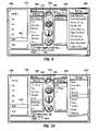
- FIGS. 7-10illustrate one way in which display 218 of the user interface 200 may be configured to appear as a user adjusts features associated with audio system 202 ( FIG. 4 ).
- display 218includes five discrete display columns: an outer left column 250 , an inner left column 252 , a central column 254 , an inner right column 256 , and an outer right column 258 .
- Display 218may also include other display elements, such as a time indicator 260 , a date indicator 262 , and a status indicator 264 .
- Central display column 254indicates the vehicular systems that may be adjusted via user interface 200 and the vehicular system that is currently selected.
- column 254may comprise a vertical row of icons each representing a different vehicular system.
- icon 280(a musical note) represents audio system 202
- icon 282(a stylized globe) represents navigation system 204
- icon 284(a thermometer) represents HVAC system 206
- icon 286(a checked box) represents driver information system 208 .
- Icons 280 , 282 , 284 , and 286may be configured to appear depressed (convex) when selected and raised (convex) when not selected.
- icon 280appears depressed to indicate that audio system 202 is currently selected. This is also indicated by status indicator 264 , which displays a suggestive graphic (i.e., a speaker) and descriptive text (i.e., “SOUND”).
- button 128( FIGS. 2 and 3 ) is utilized to select amongst audio system 202 , navigation system 204 , HVAC system 206 , and driver information system 208 .
- a user of interface 200selects a desired vehicular system by repeatedly pressing button 128 until display column 254 indicates that the desired system is selected.
- HVAC system 206When HVAC system 206 is selected, icon 284 will appear depressed and status indicator 264 will display a new graphic (e.g., an ice crystal) and textual message (e.g., “CLIMATE CONTROL”) indicative of the newly selected system. Additionally, sound generator 216 ( FIG. 4 ) may provide some form of audible feedback (e.g., a chime or message such as “climate control selected”).
- a new graphice.g., an ice crystal
- textual messagee.g., “CLIMATE CONTROL”
- sound generator 216FIG. 4
- may provide some form of audible feedbacke.g., a chime or message such as “climate control selected”.
- columns 250 , 252 , 256 , and 258will each display an option or a feature associated with the selected system.
- column 250may display audio source options (e.g., AM, FM, XM, CD, hard-disc drive, and auxiliary) and a SOUND option.
- audio source optionse.g., AM, FM, XM, CD, hard-disc drive, and auxiliary
- SOUND optionis selected (as indicated in FIG. 7 by highlight bar 260 )
- column 252may display tone balance features (e.g., the base or treble level)
- column 258may display a volume feature.
- the features displayed in columns 252 and 258are associated with the selected SOUND option as indicated in column 250 .
- columns 252 and 258will change correspondingly.
- the HDD optionis selected as shown in FIG. 9 , for example, columns 252 and 258 will each display a new feature associated with the HDD option.
- certain featuresmay be dependent only upon the selected system. For example, referring again to FIG. 7 , the selection of a particular bass level from column 252 will have no bearing on the audio source feature shown in column 250 or the volume level feature shown in column 258 .
- a usermay select amongst the options and features shown in display columns 250 , 252 , 254 , and 256 via rotary dials 120 , 122 , 124 , and 126 , respectively.
- the selection processmay simply involve rotating the dial associated with a particular feature (or option) until the associated display column indicates that the feature (or option) has been selected.
- a user wishing to adjust the volume feature of audio system 202may do so by rotating dial 126 until the desired volume setting is achieved.
- a usermay rotate dial 126 in a first direction until the volume reaches the desired level (as shown in FIG. 8 ), which may be indicated by graphic 274 and decibel display element 276 .
- Conversely, to increase the volume levela user may simply rotate dial 126 in a second direction (opposite the first direction) until the desired increase in volume is achieved.
- the tone balance option displayed in column 252contains at least two adjustable feature aspects: a first feature aspect shown in FIG. 7 (i.e., the bass level) and a second feature aspect shown in FIG. 8 (i.e., the treble level).
- a usermay navigate between these aspects by, for example, depressing the dial associated with the feature.
- a usermay press rotary dial 122 .
- a usermay then adjust the treble level by rotating dial 122 to graphically move slide 272 upward or downward on slide control 270 , or return to the bass level aspect ( FIG. 7 ) by again pressing rotary dial 122 .
- Certain selection processesmay require a user perform two steps to complete selection. First, the user may be required to specify a feature or option by rotating a rotary dial as described above. Secondly, the user may be required to select or activate that option or feature by depressing the rotary dial. For example, to choose the HDD option from the group displayed in display column 250 , a user may be required to rotate dial 120 until the HDD option is highlighted by highlight bar 260 as shown in FIG. 7 and, subsequently, depress dial 120 to select the HDD option. This type of selection process is preferable when it is not desirable to activate multiple options or features when navigating to a desired feature.
- display columns 252 , 256 , and 258will each display a different feature or option associated with the HDD option.
- columns 252 , 256 , and 258may display textual lists of artists, albums, and songs, respectively.
- status indicator 264will change to reflect the change in audio system option (i.e., the speaker graphic may change to a disc graphic and the text may change to describe the current artist, album, and song). It should thus be appreciated that the feature displayed in column 258 is dependent on the selected option from column 256 , which is, in turn, dependent on the selected option from column 252 .
- the song feature (column 258 )is dependent upon the album selected from the album option (column 256 ), which is dependent upon the artist selected from the artist option (column 252 ). If a user were to rotate dial 122 to select “Pearl Jam” from the artists option (column 252 ) as shown in FIG. 10 , the album option (column 256 ) would change to a group containing Pearl Jam albums stored on the hard-disc drive of audio system 202 .
- a user interfaceemploying a relatively intuitive and shallow menu structure (i.e., comprising no or few tiers) has been provided. It should also be appreciated that a user control for utilizing such a user interface has also been provided, which is easily accessible to a driver and a front-seat passenger of a vehicle. Additionally, it should be understood that the user interface may also be used to access and view vehicle status data (e.g., gas mileage, tire pressure, oil life, etc.). While at least one exemplary embodiment has been presented in the foregoing detailed description, it should be appreciated that a vast number of variations exist.
Landscapes
- Engineering & Computer Science (AREA)
- General Engineering & Computer Science (AREA)
- Theoretical Computer Science (AREA)
- Transportation (AREA)
- Mechanical Engineering (AREA)
- Chemical & Material Sciences (AREA)
- Combustion & Propulsion (AREA)
- Human Computer Interaction (AREA)
- Physics & Mathematics (AREA)
- General Physics & Mathematics (AREA)
- Steering Controls (AREA)
- User Interface Of Digital Computer (AREA)
- Fittings On The Vehicle Exterior For Carrying Loads, And Devices For Holding Or Mounting Articles (AREA)
Abstract
Description
Claims (7)
Priority Applications (2)
| Application Number | Priority Date | Filing Date | Title |
|---|---|---|---|
| US11/426,979US8988399B2 (en) | 2006-06-28 | 2006-06-28 | Vehicular interface including steering wheel control assembly |
| DE102007029595.4ADE102007029595B4 (en) | 2006-06-28 | 2007-06-27 | User control arrangement |
Applications Claiming Priority (1)
| Application Number | Priority Date | Filing Date | Title |
|---|---|---|---|
| US11/426,979US8988399B2 (en) | 2006-06-28 | 2006-06-28 | Vehicular interface including steering wheel control assembly |
Publications (2)
| Publication Number | Publication Date |
|---|---|
| US20080001931A1 US20080001931A1 (en) | 2008-01-03 |
| US8988399B2true US8988399B2 (en) | 2015-03-24 |
Family
ID=38876107
Family Applications (1)
| Application Number | Title | Priority Date | Filing Date |
|---|---|---|---|
| US11/426,979Active2031-04-29US8988399B2 (en) | 2006-06-28 | 2006-06-28 | Vehicular interface including steering wheel control assembly |
Country Status (2)
| Country | Link |
|---|---|
| US (1) | US8988399B2 (en) |
| DE (1) | DE102007029595B4 (en) |
Cited By (1)
| Publication number | Priority date | Publication date | Assignee | Title |
|---|---|---|---|---|
| US11372611B2 (en)* | 2018-05-25 | 2022-06-28 | Denso Corporation | Vehicular display control system and non-transitory computer readable medium storing vehicular display control program |
Families Citing this family (15)
| Publication number | Priority date | Publication date | Assignee | Title |
|---|---|---|---|---|
| JP5191115B2 (en)* | 2006-10-04 | 2013-04-24 | イーストマン コダック カンパニー | User interface device and digital camera |
| DE102010046124A1 (en)* | 2010-09-21 | 2012-03-22 | Gm Global Technology Operations Llc (N.D.Ges.D. Staates Delaware) | Information display arrangement |
| US8738224B2 (en) | 2011-01-12 | 2014-05-27 | GM Global Technology Operations LLC | Steering wheel system |
| DE102011111123A1 (en)* | 2011-08-20 | 2013-02-21 | GM Global Technology Operations LLC (n. d. Gesetzen des Staates Delaware) | Device for controlling functions of electronic devices of a vehicle and vehicle with the device |
| DE102012011179A1 (en)* | 2012-06-06 | 2013-12-12 | Gm Global Technology Operations, Llc | Device for operating a motor vehicle |
| JP2014046867A (en)* | 2012-08-31 | 2014-03-17 | Sony Corp | Input device |
| USD752056S1 (en)* | 2013-02-23 | 2016-03-22 | Samsung Electronics Co., Ltd. | Display screen or portion thereof with graphical user interface |
| DE102013217558A1 (en) | 2013-09-03 | 2015-03-05 | Continental Automotive Gmbh | Method for controlling an information display device and device with an information display device |
| CN104553668A (en)* | 2013-10-18 | 2015-04-29 | 大陆汽车投资(上海)有限公司 | Display method and display system for setup information of vehicle-mounted air conditioner |
| WO2015134639A1 (en)* | 2014-03-04 | 2015-09-11 | Panasonic Automotive Systems Company Of America, Division Of Panasonic Corporation Of North America | Configurable touch screen lcd steering wheel controls |
| US10761636B2 (en)* | 2018-03-08 | 2020-09-01 | Capital One Services, Llc | Systems and methods for providing an interactive user interface using a film and projector |
| JP7083762B2 (en)* | 2019-01-28 | 2022-06-13 | 本田技研工業株式会社 | Vehicle control device, vehicle and vehicle control method |
| JP7171472B2 (en)* | 2019-03-05 | 2022-11-15 | 株式会社東海理化電機製作所 | Steering switch device and steering switch system |
| DE102019119135A1 (en)* | 2019-07-15 | 2021-01-21 | Bayerische Motoren Werke Aktiengesellschaft | Method, device and means of locomotion for using an operating unit of a steering wheel of a means of locomotion for a first operating target and / or a second operating target |
| DE102021201200A1 (en) | 2021-02-09 | 2022-08-11 | Volkswagen Aktiengesellschaft | Method and operating device for controlling a vehicle function using a steering wheel |
Citations (27)
| Publication number | Priority date | Publication date | Assignee | Title |
|---|---|---|---|---|
| US5916288A (en)* | 1996-09-03 | 1999-06-29 | Ut Automotive Dearborn, Inc. | Multi-functional control switch arrangement |
| US5949149A (en)* | 1996-08-01 | 1999-09-07 | Matsushita Electric Industrial Co., Ltd. | Multifunctional switching apparatus and a vehicle operating system using the same |
| US6005488A (en)* | 1997-12-03 | 1999-12-21 | Ford Motor Company | User control interface architecture for automotive electronic systems |
| US20020085043A1 (en)* | 2000-12-28 | 2002-07-04 | International Business Machines Corporation | Context-responsive in-vehicle display system |
| US6418362B1 (en)* | 2000-10-27 | 2002-07-09 | Sun Microsystems, Inc. | Steering wheel interface for vehicles |
| US20020171627A1 (en)* | 2001-05-17 | 2002-11-21 | Calsonic Kansei Corporation | Operating device for operating apparatus mounted on vehicle |
| US20030023353A1 (en)* | 2000-02-18 | 2003-01-30 | Ziad Badarneh | Arrangement for a switch-equipped steering wheel |
| US6567676B1 (en)* | 2000-08-30 | 2003-05-20 | Complex Instrument Technology Corp. | Dial communication system of a steering wheel of an automobile |
| US20040046751A1 (en)* | 2000-11-14 | 2004-03-11 | Matthias Heimermann | Multifunction operating device |
| US20040050673A1 (en)* | 2002-08-28 | 2004-03-18 | Alps Electric Co., Ltd. | Steering switch for vehicle |
| US6768067B2 (en)* | 2002-11-01 | 2004-07-27 | Kabushiki Kaisha Tokai Rika Denki Seisakusho | Switch device in steering wheel and steering wheel |
| US20050012599A1 (en)* | 2003-07-17 | 2005-01-20 | Dematteo Bryan N. | Reconfigurable vehicle display |
| US20050021190A1 (en)* | 2003-07-24 | 2005-01-27 | Worrell Barry C. | Method and apparatus for accessing vehicle systems |
| US20050073195A1 (en)* | 2003-10-06 | 2005-04-07 | Popilek Mark E. | Steering wheel mounted scroll wheel and method |
| US20050167252A1 (en)* | 2004-02-04 | 2005-08-04 | Matsushita Electric Industrial Co., Ltd. | Steering wheel incorporating user-friendly switches |
| US6961644B2 (en)* | 2002-12-12 | 2005-11-01 | Alps Automotive, Inc. | Dual haptic vehicle control and display system |
| US20050247549A1 (en)* | 2004-05-07 | 2005-11-10 | Georg Wahl | Coverings for a steering wheel |
| US7026561B2 (en)* | 2003-10-09 | 2006-04-11 | Hyundai Motor Company | Remote control button assembly built in a steering wheel of a vehicle |
| US20060086022A1 (en)* | 2004-10-09 | 2006-04-27 | Would Daniel E | Method and system for re-arranging a display |
| US7129431B2 (en)* | 2005-02-08 | 2006-10-31 | Matsushita Electric Industrial Co., Ltd. | Vehicle switch assembly |
| US20070006083A1 (en)* | 2005-07-01 | 2007-01-04 | International Business Machines Corporation | Stacking portlets in portal pages |
| US7217894B2 (en)* | 2003-06-20 | 2007-05-15 | Kabushiki Kaisha Tokai Rika Denki Seisakusho | Switch apparatus for use in vehicles |
| US20070194902A1 (en)* | 2006-02-17 | 2007-08-23 | Microsoft Corporation | Adaptive heads-up user interface for automobiles |
| US20090140994A1 (en)* | 2007-12-03 | 2009-06-04 | Panasonic Corporation | Input apparatus |
| US20120120345A1 (en)* | 2009-07-23 | 2012-05-17 | Continental Automotive Systems Us, Inc. | Instrument cluster gauge |
| US20130050114A1 (en)* | 2011-08-20 | 2013-02-28 | GM Global Technology Operations LLC | Device for controlling functions of electronic devices of a vehicle and vehicle having the device |
| US20130106693A1 (en)* | 2011-10-31 | 2013-05-02 | Honda Motor Co., Ltd. | Vehicle input apparatus |
- 2006
- 2006-06-28USUS11/426,979patent/US8988399B2/enactiveActive
- 2007
- 2007-06-27DEDE102007029595.4Apatent/DE102007029595B4/enactiveActive
Patent Citations (28)
| Publication number | Priority date | Publication date | Assignee | Title |
|---|---|---|---|---|
| US5949149A (en)* | 1996-08-01 | 1999-09-07 | Matsushita Electric Industrial Co., Ltd. | Multifunctional switching apparatus and a vehicle operating system using the same |
| US5916288A (en)* | 1996-09-03 | 1999-06-29 | Ut Automotive Dearborn, Inc. | Multi-functional control switch arrangement |
| US6005488A (en)* | 1997-12-03 | 1999-12-21 | Ford Motor Company | User control interface architecture for automotive electronic systems |
| US20030023353A1 (en)* | 2000-02-18 | 2003-01-30 | Ziad Badarneh | Arrangement for a switch-equipped steering wheel |
| US6567676B1 (en)* | 2000-08-30 | 2003-05-20 | Complex Instrument Technology Corp. | Dial communication system of a steering wheel of an automobile |
| US6418362B1 (en)* | 2000-10-27 | 2002-07-09 | Sun Microsystems, Inc. | Steering wheel interface for vehicles |
| US20040046751A1 (en)* | 2000-11-14 | 2004-03-11 | Matthias Heimermann | Multifunction operating device |
| US20020085043A1 (en)* | 2000-12-28 | 2002-07-04 | International Business Machines Corporation | Context-responsive in-vehicle display system |
| US20020171627A1 (en)* | 2001-05-17 | 2002-11-21 | Calsonic Kansei Corporation | Operating device for operating apparatus mounted on vehicle |
| US20040050673A1 (en)* | 2002-08-28 | 2004-03-18 | Alps Electric Co., Ltd. | Steering switch for vehicle |
| US6768067B2 (en)* | 2002-11-01 | 2004-07-27 | Kabushiki Kaisha Tokai Rika Denki Seisakusho | Switch device in steering wheel and steering wheel |
| US6961644B2 (en)* | 2002-12-12 | 2005-11-01 | Alps Automotive, Inc. | Dual haptic vehicle control and display system |
| US7217894B2 (en)* | 2003-06-20 | 2007-05-15 | Kabushiki Kaisha Tokai Rika Denki Seisakusho | Switch apparatus for use in vehicles |
| US20050012599A1 (en)* | 2003-07-17 | 2005-01-20 | Dematteo Bryan N. | Reconfigurable vehicle display |
| US20050021190A1 (en)* | 2003-07-24 | 2005-01-27 | Worrell Barry C. | Method and apparatus for accessing vehicle systems |
| US20050073195A1 (en)* | 2003-10-06 | 2005-04-07 | Popilek Mark E. | Steering wheel mounted scroll wheel and method |
| US7026561B2 (en)* | 2003-10-09 | 2006-04-11 | Hyundai Motor Company | Remote control button assembly built in a steering wheel of a vehicle |
| US20050167252A1 (en)* | 2004-02-04 | 2005-08-04 | Matsushita Electric Industrial Co., Ltd. | Steering wheel incorporating user-friendly switches |
| US7148437B2 (en)* | 2004-05-07 | 2006-12-12 | Dr. Ing. H.C.F. Porsche Aktiengesellschaft | Coverings for a steering wheel |
| US20050247549A1 (en)* | 2004-05-07 | 2005-11-10 | Georg Wahl | Coverings for a steering wheel |
| US20060086022A1 (en)* | 2004-10-09 | 2006-04-27 | Would Daniel E | Method and system for re-arranging a display |
| US7129431B2 (en)* | 2005-02-08 | 2006-10-31 | Matsushita Electric Industrial Co., Ltd. | Vehicle switch assembly |
| US20070006083A1 (en)* | 2005-07-01 | 2007-01-04 | International Business Machines Corporation | Stacking portlets in portal pages |
| US20070194902A1 (en)* | 2006-02-17 | 2007-08-23 | Microsoft Corporation | Adaptive heads-up user interface for automobiles |
| US20090140994A1 (en)* | 2007-12-03 | 2009-06-04 | Panasonic Corporation | Input apparatus |
| US20120120345A1 (en)* | 2009-07-23 | 2012-05-17 | Continental Automotive Systems Us, Inc. | Instrument cluster gauge |
| US20130050114A1 (en)* | 2011-08-20 | 2013-02-28 | GM Global Technology Operations LLC | Device for controlling functions of electronic devices of a vehicle and vehicle having the device |
| US20130106693A1 (en)* | 2011-10-31 | 2013-05-02 | Honda Motor Co., Ltd. | Vehicle input apparatus |
Cited By (1)
| Publication number | Priority date | Publication date | Assignee | Title |
|---|---|---|---|---|
| US11372611B2 (en)* | 2018-05-25 | 2022-06-28 | Denso Corporation | Vehicular display control system and non-transitory computer readable medium storing vehicular display control program |
Also Published As
| Publication number | Publication date |
|---|---|
| DE102007029595B4 (en) | 2018-11-29 |
| DE102007029595A1 (en) | 2008-02-14 |
| US20080001931A1 (en) | 2008-01-03 |
Similar Documents
| Publication | Publication Date | Title |
|---|---|---|
| US8988399B2 (en) | Vehicular interface including steering wheel control assembly | |
| US7302322B1 (en) | Vehicular interface including armrest control assembly | |
| US7693631B2 (en) | Human machine interface system for automotive application | |
| US7680574B2 (en) | Vehicle information system with steering wheel controller | |
| JP5736323B2 (en) | Virtual feature management for vehicle information and entertainment systems | |
| US6842677B2 (en) | Vehicle user interface system and method | |
| US7126581B2 (en) | Multimode multizone interface | |
| US10303339B2 (en) | Multi-information display software switch strategy | |
| US20050021190A1 (en) | Method and apparatus for accessing vehicle systems | |
| WO2009045671A2 (en) | Software flow control of rotary quad human machine interface | |
| US20060082545A1 (en) | Human machine interface for vehicle including proximity sensor | |
| US20020080043A1 (en) | Vehicle user interface | |
| US10133473B2 (en) | Input apparatus and vehicle including the same | |
| US20060092130A1 (en) | Human machine interface for a vehicle including touch sensor | |
| EP1911623A2 (en) | Vehicular multifunction control system | |
| US20180074687A1 (en) | Steering wheel hard switch for control of mid software switches | |
| WO2018110482A1 (en) | Input device for vehicle and input method | |
| KR101442326B1 (en) | Method for controlling the display of information on a display surface | |
| CN204055393U (en) | The combination instrument that can freely programme | |
| EP2730466B1 (en) | Information display device for vehicle | |
| US20060030982A1 (en) | Vehicular multifunction control system | |
| CN100430258C (en) | Multi-module multi-area interface | |
| CN113733910A (en) | Intelligent interactive control system for motor vehicle | |
| JP6614219B2 (en) | Vehicle display device | |
| JP2019209711A (en) | Display control device for vehicle, on-vehicle equipment operation system, and gui program |
Legal Events
| Date | Code | Title | Description |
|---|---|---|---|
| AS | Assignment | Owner name:GM GLOBAL TECHNOLOGY OPERATIONS, INC., MICHIGAN Free format text:ASSIGNMENT OF ASSIGNORS INTEREST;ASSIGNORS:SZCZERBA, JOSEPH F.;LENNEMAN, JOHN K.;GEISLER, SCOTT P.;AND OTHERS;REEL/FRAME:017867/0311;SIGNING DATES FROM 20060227 TO 20060228 Owner name:GM GLOBAL TECHNOLOGY OPERATIONS, INC., MICHIGAN Free format text:ASSIGNMENT OF ASSIGNORS INTEREST;ASSIGNORS:SZCZERBA, JOSEPH F.;LENNEMAN, JOHN K.;GEISLER, SCOTT P.;AND OTHERS;SIGNING DATES FROM 20060227 TO 20060228;REEL/FRAME:017867/0311 | |
| AS | Assignment | Owner name:UNITED STATES DEPARTMENT OF THE TREASURY, DISTRICT Free format text:SECURITY AGREEMENT;ASSIGNOR:GM GLOBAL TECHNOLOGY OPERATIONS, INC.;REEL/FRAME:022195/0334 Effective date:20081231 Owner name:UNITED STATES DEPARTMENT OF THE TREASURY,DISTRICT Free format text:SECURITY AGREEMENT;ASSIGNOR:GM GLOBAL TECHNOLOGY OPERATIONS, INC.;REEL/FRAME:022195/0334 Effective date:20081231 | |
| AS | Assignment | Owner name:CITICORP USA, INC. AS AGENT FOR BANK PRIORITY SECU Free format text:SECURITY AGREEMENT;ASSIGNOR:GM GLOBAL TECHNOLOGY OPERATIONS, INC.;REEL/FRAME:022553/0493 Effective date:20090409 Owner name:CITICORP USA, INC. AS AGENT FOR HEDGE PRIORITY SEC Free format text:SECURITY AGREEMENT;ASSIGNOR:GM GLOBAL TECHNOLOGY OPERATIONS, INC.;REEL/FRAME:022553/0493 Effective date:20090409 | |
| AS | Assignment | Owner name:GM GLOBAL TECHNOLOGY OPERATIONS, INC., MICHIGAN Free format text:RELEASE BY SECURED PARTY;ASSIGNOR:UNITED STATES DEPARTMENT OF THE TREASURY;REEL/FRAME:023124/0519 Effective date:20090709 Owner name:GM GLOBAL TECHNOLOGY OPERATIONS, INC.,MICHIGAN Free format text:RELEASE BY SECURED PARTY;ASSIGNOR:UNITED STATES DEPARTMENT OF THE TREASURY;REEL/FRAME:023124/0519 Effective date:20090709 | |
| AS | Assignment | Owner name:GM GLOBAL TECHNOLOGY OPERATIONS, INC., MICHIGAN Free format text:RELEASE BY SECURED PARTY;ASSIGNORS:CITICORP USA, INC. AS AGENT FOR BANK PRIORITY SECURED PARTIES;CITICORP USA, INC. AS AGENT FOR HEDGE PRIORITY SECURED PARTIES;REEL/FRAME:023127/0402 Effective date:20090814 Owner name:GM GLOBAL TECHNOLOGY OPERATIONS, INC.,MICHIGAN Free format text:RELEASE BY SECURED PARTY;ASSIGNORS:CITICORP USA, INC. AS AGENT FOR BANK PRIORITY SECURED PARTIES;CITICORP USA, INC. AS AGENT FOR HEDGE PRIORITY SECURED PARTIES;REEL/FRAME:023127/0402 Effective date:20090814 | |
| AS | Assignment | Owner name:UNITED STATES DEPARTMENT OF THE TREASURY, DISTRICT Free format text:SECURITY AGREEMENT;ASSIGNOR:GM GLOBAL TECHNOLOGY OPERATIONS, INC.;REEL/FRAME:023156/0142 Effective date:20090710 Owner name:UNITED STATES DEPARTMENT OF THE TREASURY,DISTRICT Free format text:SECURITY AGREEMENT;ASSIGNOR:GM GLOBAL TECHNOLOGY OPERATIONS, INC.;REEL/FRAME:023156/0142 Effective date:20090710 | |
| AS | Assignment | Owner name:UAW RETIREE MEDICAL BENEFITS TRUST, MICHIGAN Free format text:SECURITY AGREEMENT;ASSIGNOR:GM GLOBAL TECHNOLOGY OPERATIONS, INC.;REEL/FRAME:023162/0093 Effective date:20090710 Owner name:UAW RETIREE MEDICAL BENEFITS TRUST,MICHIGAN Free format text:SECURITY AGREEMENT;ASSIGNOR:GM GLOBAL TECHNOLOGY OPERATIONS, INC.;REEL/FRAME:023162/0093 Effective date:20090710 | |
| AS | Assignment | Owner name:GM GLOBAL TECHNOLOGY OPERATIONS, INC., MICHIGAN Free format text:RELEASE BY SECURED PARTY;ASSIGNOR:UNITED STATES DEPARTMENT OF THE TREASURY;REEL/FRAME:025245/0587 Effective date:20100420 | |
| AS | Assignment | Owner name:GM GLOBAL TECHNOLOGY OPERATIONS, INC., MICHIGAN Free format text:RELEASE BY SECURED PARTY;ASSIGNOR:UAW RETIREE MEDICAL BENEFITS TRUST;REEL/FRAME:025314/0901 Effective date:20101026 | |
| AS | Assignment | Owner name:WILMINGTON TRUST COMPANY, DELAWARE Free format text:SECURITY AGREEMENT;ASSIGNOR:GM GLOBAL TECHNOLOGY OPERATIONS, INC.;REEL/FRAME:025327/0041 Effective date:20101027 | |
| AS | Assignment | Owner name:GM GLOBAL TECHNOLOGY OPERATIONS LLC, MICHIGAN Free format text:CHANGE OF NAME;ASSIGNOR:GM GLOBAL TECHNOLOGY OPERATIONS, INC.;REEL/FRAME:025781/0001 Effective date:20101202 | |
| AS | Assignment | Owner name:GM GLOBAL TECHNOLOGY OPERATIONS LLC, MICHIGAN Free format text:RELEASE BY SECURED PARTY;ASSIGNOR:WILMINGTON TRUST COMPANY;REEL/FRAME:034184/0001 Effective date:20141017 | |
| FEPP | Fee payment procedure | Free format text:PAYOR NUMBER ASSIGNED (ORIGINAL EVENT CODE: ASPN); ENTITY STATUS OF PATENT OWNER: LARGE ENTITY | |
| STCF | Information on status: patent grant | Free format text:PATENTED CASE | |
| MAFP | Maintenance fee payment | Free format text:PAYMENT OF MAINTENANCE FEE, 4TH YEAR, LARGE ENTITY (ORIGINAL EVENT CODE: M1551); ENTITY STATUS OF PATENT OWNER: LARGE ENTITY Year of fee payment:4 | |
| MAFP | Maintenance fee payment | Free format text:PAYMENT OF MAINTENANCE FEE, 8TH YEAR, LARGE ENTITY (ORIGINAL EVENT CODE: M1552); ENTITY STATUS OF PATENT OWNER: LARGE ENTITY Year of fee payment:8 |