US8986387B1 - Staged, bilaterally expandable trial - Google Patents
Staged, bilaterally expandable trialDownload PDFInfo
- Publication number
- US8986387B1 US8986387B1US14/480,416US201414480416AUS8986387B1US 8986387 B1US8986387 B1US 8986387B1US 201414480416 AUS201414480416 AUS 201414480416AUS 8986387 B1US8986387 B1US 8986387B1
- Authority
- US
- United States
- Prior art keywords
- central axis
- shim
- expansion
- proximal
- trial
- Prior art date
- Legal status (The legal status is an assumption and is not a legal conclusion. Google has not performed a legal analysis and makes no representation as to the accuracy of the status listed.)
- Expired - Fee Related
Links
Images


Classifications
- A—HUMAN NECESSITIES
- A61—MEDICAL OR VETERINARY SCIENCE; HYGIENE
- A61F—FILTERS IMPLANTABLE INTO BLOOD VESSELS; PROSTHESES; DEVICES PROVIDING PATENCY TO, OR PREVENTING COLLAPSING OF, TUBULAR STRUCTURES OF THE BODY, e.g. STENTS; ORTHOPAEDIC, NURSING OR CONTRACEPTIVE DEVICES; FOMENTATION; TREATMENT OR PROTECTION OF EYES OR EARS; BANDAGES, DRESSINGS OR ABSORBENT PADS; FIRST-AID KITS
- A61F2/00—Filters implantable into blood vessels; Prostheses, i.e. artificial substitutes or replacements for parts of the body; Appliances for connecting them with the body; Devices providing patency to, or preventing collapsing of, tubular structures of the body, e.g. stents
- A61F2/02—Prostheses implantable into the body
- A61F2/30—Joints
- A61F2/46—Special tools for implanting artificial joints
- A61F2/4684—Trial or dummy prostheses
- A—HUMAN NECESSITIES
- A61—MEDICAL OR VETERINARY SCIENCE; HYGIENE
- A61B—DIAGNOSIS; SURGERY; IDENTIFICATION
- A61B17/00—Surgical instruments, devices or methods
- A61B17/02—Surgical instruments, devices or methods for holding wounds open, e.g. retractors; Tractors
- A61B17/025—Joint distractors
- A—HUMAN NECESSITIES
- A61—MEDICAL OR VETERINARY SCIENCE; HYGIENE
- A61F—FILTERS IMPLANTABLE INTO BLOOD VESSELS; PROSTHESES; DEVICES PROVIDING PATENCY TO, OR PREVENTING COLLAPSING OF, TUBULAR STRUCTURES OF THE BODY, e.g. STENTS; ORTHOPAEDIC, NURSING OR CONTRACEPTIVE DEVICES; FOMENTATION; TREATMENT OR PROTECTION OF EYES OR EARS; BANDAGES, DRESSINGS OR ABSORBENT PADS; FIRST-AID KITS
- A61F2/00—Filters implantable into blood vessels; Prostheses, i.e. artificial substitutes or replacements for parts of the body; Appliances for connecting them with the body; Devices providing patency to, or preventing collapsing of, tubular structures of the body, e.g. stents
- A61F2/02—Prostheses implantable into the body
- A61F2/30—Joints
- A61F2/44—Joints for the spine, e.g. vertebrae, spinal discs
- A61F2/442—Intervertebral or spinal discs, e.g. resilient
- A61F2/4425—Intervertebral or spinal discs, e.g. resilient made of articulated components
- A—HUMAN NECESSITIES
- A61—MEDICAL OR VETERINARY SCIENCE; HYGIENE
- A61F—FILTERS IMPLANTABLE INTO BLOOD VESSELS; PROSTHESES; DEVICES PROVIDING PATENCY TO, OR PREVENTING COLLAPSING OF, TUBULAR STRUCTURES OF THE BODY, e.g. STENTS; ORTHOPAEDIC, NURSING OR CONTRACEPTIVE DEVICES; FOMENTATION; TREATMENT OR PROTECTION OF EYES OR EARS; BANDAGES, DRESSINGS OR ABSORBENT PADS; FIRST-AID KITS
- A61F2/00—Filters implantable into blood vessels; Prostheses, i.e. artificial substitutes or replacements for parts of the body; Appliances for connecting them with the body; Devices providing patency to, or preventing collapsing of, tubular structures of the body, e.g. stents
- A61F2/02—Prostheses implantable into the body
- A61F2/30—Joints
- A61F2/44—Joints for the spine, e.g. vertebrae, spinal discs
- A61F2/4455—Joints for the spine, e.g. vertebrae, spinal discs for the fusion of spinal bodies, e.g. intervertebral fusion of adjacent spinal bodies, e.g. fusion cages
- A—HUMAN NECESSITIES
- A61—MEDICAL OR VETERINARY SCIENCE; HYGIENE
- A61F—FILTERS IMPLANTABLE INTO BLOOD VESSELS; PROSTHESES; DEVICES PROVIDING PATENCY TO, OR PREVENTING COLLAPSING OF, TUBULAR STRUCTURES OF THE BODY, e.g. STENTS; ORTHOPAEDIC, NURSING OR CONTRACEPTIVE DEVICES; FOMENTATION; TREATMENT OR PROTECTION OF EYES OR EARS; BANDAGES, DRESSINGS OR ABSORBENT PADS; FIRST-AID KITS
- A61F2/00—Filters implantable into blood vessels; Prostheses, i.e. artificial substitutes or replacements for parts of the body; Appliances for connecting them with the body; Devices providing patency to, or preventing collapsing of, tubular structures of the body, e.g. stents
- A61F2/02—Prostheses implantable into the body
- A61F2/30—Joints
- A61F2/46—Special tools for implanting artificial joints
- A61F2/4603—Special tools for implanting artificial joints for insertion or extraction of endoprosthetic joints or of accessories thereof
- A61F2/4611—Special tools for implanting artificial joints for insertion or extraction of endoprosthetic joints or of accessories thereof of spinal prostheses
- A—HUMAN NECESSITIES
- A61—MEDICAL OR VETERINARY SCIENCE; HYGIENE
- A61B—DIAGNOSIS; SURGERY; IDENTIFICATION
- A61B17/00—Surgical instruments, devices or methods
- A61B17/02—Surgical instruments, devices or methods for holding wounds open, e.g. retractors; Tractors
- A61B17/025—Joint distractors
- A61B2017/0256—Joint distractors for the spine
- A—HUMAN NECESSITIES
- A61—MEDICAL OR VETERINARY SCIENCE; HYGIENE
- A61F—FILTERS IMPLANTABLE INTO BLOOD VESSELS; PROSTHESES; DEVICES PROVIDING PATENCY TO, OR PREVENTING COLLAPSING OF, TUBULAR STRUCTURES OF THE BODY, e.g. STENTS; ORTHOPAEDIC, NURSING OR CONTRACEPTIVE DEVICES; FOMENTATION; TREATMENT OR PROTECTION OF EYES OR EARS; BANDAGES, DRESSINGS OR ABSORBENT PADS; FIRST-AID KITS
- A61F2/00—Filters implantable into blood vessels; Prostheses, i.e. artificial substitutes or replacements for parts of the body; Appliances for connecting them with the body; Devices providing patency to, or preventing collapsing of, tubular structures of the body, e.g. stents
- A61F2/02—Prostheses implantable into the body
- A61F2/30—Joints
- A61F2002/30001—Additional features of subject-matter classified in A61F2/28, A61F2/30 and subgroups thereof
- A61F2002/30003—Material related properties of the prosthesis or of a coating on the prosthesis
- A61F2002/30004—Material related properties of the prosthesis or of a coating on the prosthesis the prosthesis being made from materials having different values of a given property at different locations within the same prosthesis
- A61F2002/30014—Material related properties of the prosthesis or of a coating on the prosthesis the prosthesis being made from materials having different values of a given property at different locations within the same prosthesis differing in elasticity, stiffness or compressibility
- A—HUMAN NECESSITIES
- A61—MEDICAL OR VETERINARY SCIENCE; HYGIENE
- A61F—FILTERS IMPLANTABLE INTO BLOOD VESSELS; PROSTHESES; DEVICES PROVIDING PATENCY TO, OR PREVENTING COLLAPSING OF, TUBULAR STRUCTURES OF THE BODY, e.g. STENTS; ORTHOPAEDIC, NURSING OR CONTRACEPTIVE DEVICES; FOMENTATION; TREATMENT OR PROTECTION OF EYES OR EARS; BANDAGES, DRESSINGS OR ABSORBENT PADS; FIRST-AID KITS
- A61F2/00—Filters implantable into blood vessels; Prostheses, i.e. artificial substitutes or replacements for parts of the body; Appliances for connecting them with the body; Devices providing patency to, or preventing collapsing of, tubular structures of the body, e.g. stents
- A61F2/02—Prostheses implantable into the body
- A61F2/30—Joints
- A61F2002/30001—Additional features of subject-matter classified in A61F2/28, A61F2/30 and subgroups thereof
- A61F2002/30108—Shapes
- A61F2002/3011—Cross-sections or two-dimensional shapes
- A61F2002/30138—Convex polygonal shapes
- A61F2002/30154—Convex polygonal shapes square
- A—HUMAN NECESSITIES
- A61—MEDICAL OR VETERINARY SCIENCE; HYGIENE
- A61F—FILTERS IMPLANTABLE INTO BLOOD VESSELS; PROSTHESES; DEVICES PROVIDING PATENCY TO, OR PREVENTING COLLAPSING OF, TUBULAR STRUCTURES OF THE BODY, e.g. STENTS; ORTHOPAEDIC, NURSING OR CONTRACEPTIVE DEVICES; FOMENTATION; TREATMENT OR PROTECTION OF EYES OR EARS; BANDAGES, DRESSINGS OR ABSORBENT PADS; FIRST-AID KITS
- A61F2/00—Filters implantable into blood vessels; Prostheses, i.e. artificial substitutes or replacements for parts of the body; Appliances for connecting them with the body; Devices providing patency to, or preventing collapsing of, tubular structures of the body, e.g. stents
- A61F2/02—Prostheses implantable into the body
- A61F2/30—Joints
- A61F2002/30001—Additional features of subject-matter classified in A61F2/28, A61F2/30 and subgroups thereof
- A61F2002/30108—Shapes
- A61F2002/3011—Cross-sections or two-dimensional shapes
- A61F2002/30159—Concave polygonal shapes
- A61F2002/30179—X-shaped
- A—HUMAN NECESSITIES
- A61—MEDICAL OR VETERINARY SCIENCE; HYGIENE
- A61F—FILTERS IMPLANTABLE INTO BLOOD VESSELS; PROSTHESES; DEVICES PROVIDING PATENCY TO, OR PREVENTING COLLAPSING OF, TUBULAR STRUCTURES OF THE BODY, e.g. STENTS; ORTHOPAEDIC, NURSING OR CONTRACEPTIVE DEVICES; FOMENTATION; TREATMENT OR PROTECTION OF EYES OR EARS; BANDAGES, DRESSINGS OR ABSORBENT PADS; FIRST-AID KITS
- A61F2/00—Filters implantable into blood vessels; Prostheses, i.e. artificial substitutes or replacements for parts of the body; Appliances for connecting them with the body; Devices providing patency to, or preventing collapsing of, tubular structures of the body, e.g. stents
- A61F2/02—Prostheses implantable into the body
- A61F2/30—Joints
- A61F2002/30001—Additional features of subject-matter classified in A61F2/28, A61F2/30 and subgroups thereof
- A61F2002/30108—Shapes
- A61F2002/30199—Three-dimensional shapes
- A61F2002/30261—Three-dimensional shapes parallelepipedal
- A61F2002/30266—Three-dimensional shapes parallelepipedal wedge-shaped parallelepipeds
- A—HUMAN NECESSITIES
- A61—MEDICAL OR VETERINARY SCIENCE; HYGIENE
- A61F—FILTERS IMPLANTABLE INTO BLOOD VESSELS; PROSTHESES; DEVICES PROVIDING PATENCY TO, OR PREVENTING COLLAPSING OF, TUBULAR STRUCTURES OF THE BODY, e.g. STENTS; ORTHOPAEDIC, NURSING OR CONTRACEPTIVE DEVICES; FOMENTATION; TREATMENT OR PROTECTION OF EYES OR EARS; BANDAGES, DRESSINGS OR ABSORBENT PADS; FIRST-AID KITS
- A61F2/00—Filters implantable into blood vessels; Prostheses, i.e. artificial substitutes or replacements for parts of the body; Appliances for connecting them with the body; Devices providing patency to, or preventing collapsing of, tubular structures of the body, e.g. stents
- A61F2/02—Prostheses implantable into the body
- A61F2/30—Joints
- A61F2002/30001—Additional features of subject-matter classified in A61F2/28, A61F2/30 and subgroups thereof
- A61F2002/30316—The prosthesis having different structural features at different locations within the same prosthesis; Connections between prosthetic parts; Special structural features of bone or joint prostheses not otherwise provided for
- A61F2002/30535—Special structural features of bone or joint prostheses not otherwise provided for
- A61F2002/30537—Special structural features of bone or joint prostheses not otherwise provided for adjustable
- A61F2002/30545—Special structural features of bone or joint prostheses not otherwise provided for adjustable for adjusting a diameter
- A—HUMAN NECESSITIES
- A61—MEDICAL OR VETERINARY SCIENCE; HYGIENE
- A61F—FILTERS IMPLANTABLE INTO BLOOD VESSELS; PROSTHESES; DEVICES PROVIDING PATENCY TO, OR PREVENTING COLLAPSING OF, TUBULAR STRUCTURES OF THE BODY, e.g. STENTS; ORTHOPAEDIC, NURSING OR CONTRACEPTIVE DEVICES; FOMENTATION; TREATMENT OR PROTECTION OF EYES OR EARS; BANDAGES, DRESSINGS OR ABSORBENT PADS; FIRST-AID KITS
- A61F2/00—Filters implantable into blood vessels; Prostheses, i.e. artificial substitutes or replacements for parts of the body; Appliances for connecting them with the body; Devices providing patency to, or preventing collapsing of, tubular structures of the body, e.g. stents
- A61F2/02—Prostheses implantable into the body
- A61F2/30—Joints
- A61F2002/30001—Additional features of subject-matter classified in A61F2/28, A61F2/30 and subgroups thereof
- A61F2002/30316—The prosthesis having different structural features at different locations within the same prosthesis; Connections between prosthetic parts; Special structural features of bone or joint prostheses not otherwise provided for
- A61F2002/30535—Special structural features of bone or joint prostheses not otherwise provided for
- A61F2002/30537—Special structural features of bone or joint prostheses not otherwise provided for adjustable
- A61F2002/3055—Special structural features of bone or joint prostheses not otherwise provided for adjustable for adjusting length
- A—HUMAN NECESSITIES
- A61—MEDICAL OR VETERINARY SCIENCE; HYGIENE
- A61F—FILTERS IMPLANTABLE INTO BLOOD VESSELS; PROSTHESES; DEVICES PROVIDING PATENCY TO, OR PREVENTING COLLAPSING OF, TUBULAR STRUCTURES OF THE BODY, e.g. STENTS; ORTHOPAEDIC, NURSING OR CONTRACEPTIVE DEVICES; FOMENTATION; TREATMENT OR PROTECTION OF EYES OR EARS; BANDAGES, DRESSINGS OR ABSORBENT PADS; FIRST-AID KITS
- A61F2/00—Filters implantable into blood vessels; Prostheses, i.e. artificial substitutes or replacements for parts of the body; Appliances for connecting them with the body; Devices providing patency to, or preventing collapsing of, tubular structures of the body, e.g. stents
- A61F2/02—Prostheses implantable into the body
- A61F2/30—Joints
- A61F2002/30001—Additional features of subject-matter classified in A61F2/28, A61F2/30 and subgroups thereof
- A61F2002/30316—The prosthesis having different structural features at different locations within the same prosthesis; Connections between prosthetic parts; Special structural features of bone or joint prostheses not otherwise provided for
- A61F2002/30535—Special structural features of bone or joint prostheses not otherwise provided for
- A61F2002/30537—Special structural features of bone or joint prostheses not otherwise provided for adjustable
- A61F2002/30556—Special structural features of bone or joint prostheses not otherwise provided for adjustable for adjusting thickness
- A—HUMAN NECESSITIES
- A61—MEDICAL OR VETERINARY SCIENCE; HYGIENE
- A61F—FILTERS IMPLANTABLE INTO BLOOD VESSELS; PROSTHESES; DEVICES PROVIDING PATENCY TO, OR PREVENTING COLLAPSING OF, TUBULAR STRUCTURES OF THE BODY, e.g. STENTS; ORTHOPAEDIC, NURSING OR CONTRACEPTIVE DEVICES; FOMENTATION; TREATMENT OR PROTECTION OF EYES OR EARS; BANDAGES, DRESSINGS OR ABSORBENT PADS; FIRST-AID KITS
- A61F2/00—Filters implantable into blood vessels; Prostheses, i.e. artificial substitutes or replacements for parts of the body; Appliances for connecting them with the body; Devices providing patency to, or preventing collapsing of, tubular structures of the body, e.g. stents
- A61F2/02—Prostheses implantable into the body
- A61F2/30—Joints
- A61F2002/30001—Additional features of subject-matter classified in A61F2/28, A61F2/30 and subgroups thereof
- A61F2002/30316—The prosthesis having different structural features at different locations within the same prosthesis; Connections between prosthetic parts; Special structural features of bone or joint prostheses not otherwise provided for
- A61F2002/30535—Special structural features of bone or joint prostheses not otherwise provided for
- A61F2002/30563—Special structural features of bone or joint prostheses not otherwise provided for having elastic means or damping means, different from springs, e.g. including an elastomeric core or shock absorbers
- A—HUMAN NECESSITIES
- A61—MEDICAL OR VETERINARY SCIENCE; HYGIENE
- A61F—FILTERS IMPLANTABLE INTO BLOOD VESSELS; PROSTHESES; DEVICES PROVIDING PATENCY TO, OR PREVENTING COLLAPSING OF, TUBULAR STRUCTURES OF THE BODY, e.g. STENTS; ORTHOPAEDIC, NURSING OR CONTRACEPTIVE DEVICES; FOMENTATION; TREATMENT OR PROTECTION OF EYES OR EARS; BANDAGES, DRESSINGS OR ABSORBENT PADS; FIRST-AID KITS
- A61F2/00—Filters implantable into blood vessels; Prostheses, i.e. artificial substitutes or replacements for parts of the body; Appliances for connecting them with the body; Devices providing patency to, or preventing collapsing of, tubular structures of the body, e.g. stents
- A61F2/02—Prostheses implantable into the body
- A61F2/30—Joints
- A61F2002/30001—Additional features of subject-matter classified in A61F2/28, A61F2/30 and subgroups thereof
- A61F2002/30316—The prosthesis having different structural features at different locations within the same prosthesis; Connections between prosthetic parts; Special structural features of bone or joint prostheses not otherwise provided for
- A61F2002/30535—Special structural features of bone or joint prostheses not otherwise provided for
- A61F2002/30565—Special structural features of bone or joint prostheses not otherwise provided for having spring elements
- A—HUMAN NECESSITIES
- A61—MEDICAL OR VETERINARY SCIENCE; HYGIENE
- A61F—FILTERS IMPLANTABLE INTO BLOOD VESSELS; PROSTHESES; DEVICES PROVIDING PATENCY TO, OR PREVENTING COLLAPSING OF, TUBULAR STRUCTURES OF THE BODY, e.g. STENTS; ORTHOPAEDIC, NURSING OR CONTRACEPTIVE DEVICES; FOMENTATION; TREATMENT OR PROTECTION OF EYES OR EARS; BANDAGES, DRESSINGS OR ABSORBENT PADS; FIRST-AID KITS
- A61F2/00—Filters implantable into blood vessels; Prostheses, i.e. artificial substitutes or replacements for parts of the body; Appliances for connecting them with the body; Devices providing patency to, or preventing collapsing of, tubular structures of the body, e.g. stents
- A61F2/02—Prostheses implantable into the body
- A61F2/30—Joints
- A61F2002/30001—Additional features of subject-matter classified in A61F2/28, A61F2/30 and subgroups thereof
- A61F2002/30316—The prosthesis having different structural features at different locations within the same prosthesis; Connections between prosthetic parts; Special structural features of bone or joint prostheses not otherwise provided for
- A61F2002/30535—Special structural features of bone or joint prostheses not otherwise provided for
- A61F2002/30579—Special structural features of bone or joint prostheses not otherwise provided for with mechanically expandable devices, e.g. fixation devices
Definitions
- the teachings hereinare directed to systems and methods for distracting an intervertebral disc space using a staged, bilaterally expandable trial.
- Bone graftsare used in spinal fusion, for example, which is a technique used to stabilize the spinal bones, or vertebrae, and a goal is to create a solid bridge of bone between two or more vertebrae.
- the fusion processincludes “arthrodesis”, which can be thought of as the mending or welding together of two bones in a spinal joint space, much like a broken arm or leg healing in a cast.
- Spinal fusionmay be recommended for a variety of conditions that might include, for example, a spondylolisthesis, a degenerative disc disease, a recurrent disc herniation, or perhaps to correct a prior surgery.
- Bone graft materialis introduced for fusion and a fusion cage can be inserted to help support the disc space during the fusion process.
- fusion cagesare frequently used in such procedures to support and stabilize the disc space until bone graft unites the bone of the opposing vertebral endplates in the disc space.
- a transforaminal lumbar interbody fusion (TLIF)involves placement of posterior instrumentation (screws and rods) into the spine, and the fusion cage loaded with bone graft can be inserted into the disc space.
- TLIFtransforaminal lumbar interbody fusion
- Bone graft materialcan be pre-packed in the disc space or packed after the cage is inserted.
- TLIFcan be used to facilitate stability in the front and back parts of the lumbar spine promoting interbody fusion in the anterior portion of the spine. Fusion in this region can be beneficial, because the anterior interbody space includes an increased area for bone to heal, as well as to handle increased forces that are distributed through this area.
- distraction systemsthat facilitate an improved placement of distraction stresses across the verterbral endplates that define the distracted intervertebral space.
- Such systemsare provided herein, the systems configured to (i) effectively and selectively place the distraction stresses in areas that include areas at or near the peripheral zones of the vertebral endplates to reduce the incidence of subsidence; (ii) reduce or eliminate the problem of failures resulting from subsidence; (iii) have a small maximum dimension of the trial in a collapsed state for a low-profile insertion into the annulus in a minimally-invasive manner, whether using only a unilateral approach or a bilateral approach; (iv) laterally expand within the intervertebral space to facilitate the effective and selective distribution of distraction stresses on the vertebral endplates; (v) vertically expand for distraction of the intervertebral space; (vi) provide an expansion in the intervertebral space without contracting the system in length to maintain a large footprint during the distraction process, distributing
- the teachings hereinare directed to systems and methods for distracting an intervertebral disc space using a staged, bilaterally expandable trial.
- the teachingsare directed to a method of distracting an intervertebral space in a manner that addresses the problem of subsidence.
- the teachingsinclude obtaining a bilaterally expandable trial that is configured to first expand laterally and then expand vertically to distract an intervertebral space having a top vertebral plate and a bottom vertebral plate. The trial is then inserted into the intervertebral space in a collapsed state. Once inserted, the trial then used for distracting the intervertebral space using a staged, bilateral expansion, the distracting including a first stage and a second stage.
- the first stageincludes expanding the trial laterally toward the peripheral zones of the top vertebral plate and the bottom vertebral plate
- the second stageincludes expanding the trial vertically to distract the intervertebral space.
- the trialcomprises a bilaterally-expandable shell having a proximal region with an end, a mid-region, a distal region with an end, and a lumen.
- the proximal regioncan have a slider-guide
- the distal regioncan have a bilaterally-expandable head with 4 subheads that include a first top beam, a second top beam, a first bottom beam, and a second bottom beam.
- the mid-regioncan have 4 flex rods that include a first top flex rod, a second top flex rod, a first bottom flex rod, and a second bottom flex rod, each of which operably attaches the slider-guide to it's respective subhead.
- One or more beam stabilizerscan be included stabilize and/or align the subheads during operation of the device.
- a beam stabilizerfor example, can slidably translate, such that it is telescopic with respect to one or both subheads between which it is operably attached to stabilize and/or align the relationship between the subheads during operation of the device.
- the beamscan be stabilized with translatable, telescopic linear guides, such that the linear guide can telescope within itself.
- the first top beamcan be operably connected to the second top beam with a top telescopic beam stabilizer
- the first top beamcan be operably connected to the second top beam with a top telescopic beam stabilizer
- the first top beamcan be operably connected to the first bottom beam with a first side telescopic beam stabilizer
- the second top beamcan be operably connected to the second bottom beam with a second side telescopic beam stabilizer
- the first bottom beamcan be operably connected to the second bottom beam with a bottom telescopic beam stabilizer.
- the beam stabilizer, or at least a portion thereofcan be fixably attached, or monolithically integral to, one or both beams between which it is operably connected or positioned in either a fixed or translatable configuration in the trial.
- the trialcan be expanded first laterally, and then vertically, using any means known to one of skill.
- the trialcan also comprise a shim having a proximal region with an end; a mid-region; a distal region with an end; a central axis; a top surface with a first top-lateral surface and a second top-lateral surface; a bottom surface with a first bottom-lateral surface and a second bottom-lateral surface; a first side surface with a first top-side surface and a first bottom-side surface; and, a second side surface with a second top-side surface and a second bottom-side surface.
- the shimcan be configured for a proximal-to-distal axial translation in the lumen of the shell that induces a lateral force on the 4 subheads followed by a vertical force on the 4 subheads for a staged, bilateral expansion in vivo that includes a lateral expansion of the head followed by a vertical expansion of the head in an intervertebral space having a top vertebral endplate, a bottom vertebral endplate, and an annulus.
- the head of the trialcan be configured with a proximal portion having an end; a distal portion having an end; and, a central shell axis of the expanded state; the head adapted for slidably-engaging with the shim in vivo following placement of the trial in the intervertebral space through the annular opening, the slidably-engaging including axially-translating the shim in the lumen of the shell from the proximal end of the lumen toward the distal end of the lumen in vivo; the translating including keeping the central shim axis at least substantially coincident with the central shell axis during the translating.
- the teachingsare also directed to systems that include means for applying an axial proximal-to-distal force on a shim that expands the trial.
- the proximal end of the shimcan be configured to receive the axial proximal-to-distal force through an actuation bar for the axial translation, the actuation bar having a proximal portion with a proximal end, a distal portion with a distal end, and configured to transfer the axial proximal-to-distal force to the shim through the slider-guide.
- the systemscan include an actuation means operably attached to the proximal end of the actuation bar to transfer the axial proximal-to-distal force to the shim through the distal end of the actuation bar.
- the actuation barreceives the axial proximal-to-distal force from an actuation screw that can be operably attached to the proximal end of the actuation bar to transfer the force to the shim through the distal end of the actuation bar.
- the systemscan further comprise a retractable retention plunger configured for retaining the trial in the collapsed state and releasing the trial for expansion into the expanded state.
- the head of the trialcan have a collapsed dimension that facilitates insertion to the intervertebral space and an expanded dimension that facilitates the desired lateral expansion and vertical expansion in the intervertebral space.
- the head of the trialcan have a collapsed state with a transverse cross-section having a maximum dimension ranging from 5 mm to 18 mm for placing the frame in an intervertebral space through an annular opening for expansion in the intervertebral space.
- the head of the trialcan have an expanded state with a transverse cross-section having a maximum dimension ranging from 6.5 mm to 28 mm, 7.5 mm to 28 mm, 8.5 mm to 28 mm, 6.5 mm to 27 mm, 6.5 mm to 25 mm, 6.5 mm to 23 mm, 6.5 mm to 21 mm, 6.5 mm to 19 mm, 6.5 mm to 18 mm, or any range therein in increments of 1 mm, in the intervertebral space.
- the shimcan have a transverse cross-section with a maximum dimension ranging from 5 mm to 18 mm, 6 mm to 18 mm, 7 mm to 18 mm, 5 mm to 15 mm, 5 mm to 16 mm, 5 mm to 17 mm, or any range therein in increments of 1 mm, for translating the shim in the lumen of the shell.
- the shimcan have a horizontal wedge configured to laterally-expand the trial, and a vertical wedge configured to vertically-expand the trial.
- the shimcan have a top wedge configured to laterally-expand the first top beam away from the second top beam, a bottom wedge configured to laterally-expand the first bottom beam away from the second bottom beam, a first side wedge configured to vertically-expand the first top beam away from the first bottom beam, and a second side wedge configured to vertically-expand the second top beam away from the second bottom beam.
- the proximal portion of the first top beam and the proximal portion of the second top beamcan be configured to complement the top wedge at the onset of the lateral expansion during the proximal-to-distal axial translation; and, the proximal portion of the first bottom beam and the proximal portion of the second bottom beam can be configured to complement the bottom wedge at the onset of the lateral expansion during the proximal-to-distal axial translation.
- the distance, D STAGINGbetween the onset of the lateral expansion and the onset of the vertical translation can range from 2 mm to 10 mm.
- the proximal portion of the first top beam and the proximal portion of the first bottom beamcan be configured to complement the first side wedge during the proximal-to-distal axial translation for the vertical expansion; and, the proximal portion of the second top beam and the proximal portion of the second bottom beam can be configured to complement the second side wedge during the proximal-to-distal axial translation for the vertical expansion.
- the first top beamcan include a proximal portion having an end, a distal portion having an end, and a central axis; the first top beam configured for contacting a first top chamfer of the shim in the expanded state, the central axis of the first top beam at least substantially on (i) a top plane containing the central axis of the first top beam and the central axis of a second top beam and (ii) a first side plane containing the central axis of the first top beam and the central axis of a first bottom beam.
- the second top beamcan include a proximal portion having an end, a distal portion having an end, and a central axis; the second top beam configured for contacting a second top chamfer of the shim in the expanded state, the central axis of the second top beam at least substantially on (i) the top plane and (ii) a second side plane containing the central axis of the second top beam and the central axis of a second bottom beam.
- the first bottom beamcan include a proximal portion having an end, a distal portion having an end, and a central axis; the first bottom beam configured for contacting a first bottom chamfer of the shim in the expanded state, the central axis of the first bottom beam at least substantially on (i) a bottom plane containing the central axis of the first bottom beam and the central axis of a second top beam and (ii) the first side plane.
- the second bottom beamcan include a proximal portion having an end, a distal portion having an end, and a central axis; the second bottom beam configured for contacting a second bottom chamfer of the shim in the expanded state, the central axis of the second bottom beam being at least substantially on (i) the bottom plane and (ii) a second side plane containing the central axis of the second bottom beam and the second top beam.
- the first top beamcan include a proximal portion having an end, a distal portion having an end, and a central axis; the first top beam configured for contacting a first top-lateral surface of the shim and a first top-side surface of the shim in the expanded state, the central axis of the first top beam at least substantially on (i) a top plane containing the central axis of the first top beam and the central axis of a second top beam and (ii) a first side plane containing the central axis of the first top beam and the central axis of a first bottom beam.
- the second top beamcan include a proximal portion having an end, a distal portion having an end, and a central axis; the second top beam configured for contacting the second top-lateral surface of the shim and the second top-side surface of the shim in the expanded state, the central axis of the second top beam at least substantially on (i) the top plane and (ii) a second side plane containing the central axis of the second top beam and the central axis of a second bottom beam.
- the first bottom beamcan include a proximal portion having an end, a distal portion having an end, and a central axis; the first bottom beam configured for contacting the first bottom-lateral surface of the shim and the first bottom-side surface of the shim in the expanded state, the central axis of the first bottom beam at least substantially on (i) a bottom plane containing the central axis of the first bottom beam and the central axis of a second top beam and (ii) the first side plane.
- the second bottom beamcan include a proximal portion having an end, a distal portion having an end, and a central axis; the second bottom beam configured for contacting the second bottom-lateral surface of the shim and the second bottom-side surface of the shim in the expanded state, the central axis of the second bottom beam being at least substantially on (i) the bottom plane and (ii) a second side plane containing the central axis of the second bottom beam and the second top beam.
- the shimcan comprise a lateral-expansion wedge with angle ⁇ L ranging from 10° to 30° and a vertical-expansion wedge with angle ⁇ V ranging from 30° to 50°, the apex of the lateral-expansion wedge and the apex of the vertical-expansion wedge each at least substantially on a single plane that is orthogonal to the central axis of the shim, and the ratio of ⁇ V : ⁇ L ranges from 1:1.25 to 1:4 to stage the bilateral expansion of the head.
- the shimcan comprise a lateral-expansion wedge with angle ⁇ L ranging from 10° to 90° and a vertical-expansion wedge with angle ⁇ V ranging from 10° to 90°, the apex of the lateral-expansion wedge on a first plane and the apex of the vertical expansion wedge on a second plane, both the first plane and the second plane being orthogonal to the central axis of the shim and separated on the central axis at a distance ranging from 2 mm to 10 mm to stage the bilateral expansion of the head.
- the shellcan be formed using any method of construction known to one of skill, for example, multi-component or single unit.
- the shellcan be a single-unit formed from a single body of material, and the slider-guide, head, and flex rods can be monolithically integral.
- the teachingsinclude a method of distracting an intervertebral space using the trials taught herein.
- the methodcan comprise creating a point of entry into an intervertebral disc, the intervertebral disc having a nucleus pulposus surrounded by an annulus fibrosis, and the point of entry having the maximum lateral dimension created through the annulus fibrosis.
- the methodscan include removing the nucleus pulposus from within the intervertebral disc through the point of entry, leaving the intervertebral space for expansion of the head of the trial within the annulus fibrosis, the intervertebral space having the top vertebral plate and the bottom vertebral plate.
- the methodscan include inserting the head in the collapsed state through the point of entry into the intervertebral space; and, distracting the intervertebral space using a staged, bilateral expansion that includes a first stage and a second stage.
- the distractingcan include a first stage and a second stage, the first stage including expanding the head laterally toward the peripheral zones of the top vertebral plate and the bottom vertebral plate; and, the second stage including expanding the head vertically to distract the intervertebral space, the pressure for the expansion occurring preferably, and at least primarily, at or near the peripheral zones of the top vertebral plate and the bottom vertebral plate.
- the lateral dimension of the point of entryranges from about 5 mm to 18 mm, 6 mm to 18 mm, 7 mm to 18 mm, 5 mm to 15 mm, 5 mm to 16 mm, 5 mm to 17 mm, or any range therein in increments of 1 mm.
- the distractingincludes selecting an amount of lateral expansion independent of an amount of vertical expansion. And, in some embodiments, the distracting includes measuring the amount of lateral expansion independent of the amount of vertical expansion.
- the distractingincludes as a first stage of lateral expansion, inserting a top wedge into the head between the first top beam and the second top beam, the top wedge composing a portion of the shim and configured to laterally-expand the first top beam away from the second top beam; and, inserting a bottom wedge into the head between the first bottom beam and the second bottom beam, the bottom wedge configured to laterally-expand the first bottom beam away from the second bottom beam.
- first side wedgeinto the head between the first top beam and the first bottom beam, the first side wedge configured to laterally-expand the first top beam away from the first bottom beam; and, inserting a second side wedge into the head between the second top beam and the second bottom beam, the second side wedge configured to laterally-expand the second top beam away from the second bottom beam.
- the distractingincludes selecting a shim having a lateral-expansion wedge with angle ⁇ L ranging from 10° to 30° and a vertical-expansion wedge with angle ⁇ V ranging from 30° to 50°, the apex of the lateral-expansion wedge and the apex of the vertical-expansion wedge each at least substantially on a single plane that is orthogonal to the central axis of the shim, and the ratio of ⁇ V : ⁇ L ranges from 1:1.25 to 1:4 to stage the bilateral expansion of the head.
- the distractingincludes selecting a shim having a lateral-expansion wedge with angle ⁇ L ranging from 10° to 90° and a vertical-expansion wedge with angle ⁇ V ranging from 10° to 90°, the apex of the lateral-expansion wedge on a first plane and the apex of the vertical expansion wedge on a second plane, both the first plane and the second plane being orthogonal to the central axis of the shim and separated on the central axis at a distance ranging from 2 mm to 10 mm to stage the bilateral expansion of the head.
- FIGS. 1A and 1Billustrate a sketch of an endplate of a vertebral body and a representative photograph of an intervertebral space using a cadaver intervertebral body and disc, according to some embodiments.
- FIG. 2illustrates a process of using a staged, bilaterally-expandable trial for distracting an intervertebral space, according to some embodiments.
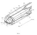
- FIGS. 3A-3Dillustrate a staged, bilaterally-expandable trial, according to some embodiments.
- FIGS. 4A-4Dillustrate a shim for the staged, bilaterally expanding trial, according to some embodiments.
- FIG. 5illustrates the concept of the staged, bilateral expansion of the trial, according to some embodiments.
- FIG. 6illustrates a trial system for a staged, bilateral expansion of the trial in an intervertebral space, according to some embodiments.
- FIGS. 7A and 7Billustrate a trial system with an expansion gauge and a retractable retention plunger for retaining the trial prior to a staged, bilateral expansion of the trial in an intervertebral space, according to some embodiments.
- FIGS. 8A-8Dillustrate a staged, bilaterally-expandable trial with beam stabilizers that telescope within themselves, according to some embodiments.
- FIGS. 9A-9Dillustrate a staged, bilaterally-expandable trial with beam stabilizers that telescope with one or both subheads having a counter-bore, according to some embodiments.
- a system for distracting an intervertebral disc space using a staged, bilaterally expandable trialis provided.
- teachingsare directed to a method of distracting an intervertebral space in a manner that addresses the problem of subsidence by selectively applying distraction forces to stronger portions of the vertebral endplates of the intervertebral space.
- the term “trial”can be used interchangeably with the term “distractor” in many embodiments.
- FIGS. 1A and 1Billustrate a sketch of an endplate of a vertebral body and a representative photograph of an intervertebral space using a cadaver intervertebral body and disc, according to some embodiments.
- This illustrationprovides a reference to discuss the state-of-the-art methods of introducing the fusion cage and bone graft material which create “subsidence” of the cage into the adjoining vertebrae, resulting in a narrowing of the formerly distracted disc space.
- the vertebral body 100has an endplate 105 with a mid-region 115 and a peripheral zone 125 .
- FIG. 1Billustrates a cadaver intervertebral body 150 , and the annulus 153 that surrounds the intervertebral space 155 that receives the trial.
- the phrase “at or near the peripheral zone” of a vertebral endplatecan be interpreted as meaning “at least substantially away from the central portion of the area of the vertebral endplate.
- a distraction pressurecan be applied, for example, at least substantially away from the central portion where greater than 30%, greater than 35%, greater than 40%, greater than 45%, greater than 50%, greater than 55%, greater than 60%, greater than 65%, greater than 70%, greater than 75%, greater than 80%, greater than 85%, greater than 90%, greater than 95%, or more of the surface area of a pair of subheads that is facing, or in some embodiments in contact or potential contact with, their respective endplate outside of the central portion.
- the “central portion”can be defined as a scaled-down area on the surface of the endplate, and thus sharing a plane with the surface of the endplate, sharing a center-point on the plane, and sharing the same general shape as the total area of the endplate, albeit scaled-down.
- an overlay of the central portion that is placed on the total area with the same orientation, and placed carefully such that the center-point of the central portion is shared/concentric with the center-point of the total arealeaves a “remaining area” or “remainder” around the periphery of the total area that can be defined, for example, as either a “peripheral zone” in some embodiments, or “at-or-near the peripheral zone,” in some embodiments.
- the following tableshows a hypothetical relationship between the radius and the area of a hypothetical endplate model using for simplicity a circular area having a diameter of 25 mm.
- a central portion of the hypothetical circular area having area based on a radius of 6.85 mm, which is about 55% of the total radiusprovides only 30% of the total area.
- the central portioncan be 10%, 15%, 20%, 25%, 30%, 35%, 40%, 45%, 50%, 55%, 60%, 65%, 70%, or any percentage therein increments of 1%, of the total area.
- the peripheral zonecan have a radial dimension, or radial width, that is 2 mm, 3 mm, 4 mm, 5 mm, 6 mm, 7 mm, 8 mm, or any 0.1 mm increment therein.
- the radial dimension, or radial widthis the thickness of the peripheral zone area that circumscribes the periphery of the endplate as shown in FIG. 1 , 125 , and further described above qualitatively with respect to the remainder of the overlay of the central portion on the total area.
- a peripheral zonedoes not have to be uniform, and that the teachings provided herein to define the peripheral zone, or the area at-or-near the peripheral zone, are taught to further clarify boundaries of some embodiments by distinguishing both a configuration and function of the trials and systems taught herein from the current state-of-the-art.
- the trialscan be further configured to have a contour, whether laterally, vertically, or both laterally and vertically, that is at least substantially complementary to the areas within the peripheral zone, or at-or-near the peripheral zone, during operation of the trials provided herein.
- the trialcan have a linear, curved, or curvalinear lateral surface; a flat or convex vertical surface; or, some combination thereof, upon expansion to provide a shape that is at least substantially complementary to the peripheral zone of the endplates upon expansion.
- FIG. 2illustrates a process of using a staged, bilaterally-expandable trial for distracting an intervertebral space, according to some embodiments.
- the method 200 of distracting an intervertebral spacecan include, for example, obtaining a bilaterally expandable trial that is configured to first expand laterally and then expand vertically to distract an intervertebral space having a top vertebral plate and a bottom vertebral plate.
- the method 200includes creating 205 a point of entry into an intervertebral disc and removing 210 the nucleus pulposus from within the intervertebral disc to create an intervertebral space.
- the methodfurther includes inserting 215 the trial into the intervertebral space in a collapsed state.
- the trialthen used for distracting 220 the intervertebral space using a staged, bilateral expansion, the distracting including a first stage and a second stage.
- the first stageincludes laterally expanding 225 the trial to a position at or near the peripheral zones of the top vertebral plate and the bottom vertebral plate
- the second stageincludes vertically expanding 230 the trial at or near the peripheral zones of the top vertebral plate and the bottom vertebral plate to distract the intervertebral space while avoid the problem of subsidence.
- FIGS. 3A-3Dillustrate a staged, bilaterally-expandable trial, according to some embodiments.
- the trial 300comprises a bilaterally-expandable shell having a proximal region 301 with an end 302 , a mid-region 303 , a distal region 305 with an end 306 , and a lumen 307 .
- FIG. 3Aa top view of the trial 300
- the trial 300comprises a bilaterally-expandable shell having a proximal region 301 with an end 302 , a mid-region 303 , a distal region 305 with an end 306 , and a lumen 307 .
- the proximal region 301can have a slider-guide 310
- the distal region 305can have a bilaterally-expandable head 315 with 4 subheads 316 , 317 , 318 , 319 that include a first top beam 316 , a second top beam 317 , a first bottom beam 318 , and a second bottom beam 319 .
- the mid-regioncan have 4 flex rods 321 , 322 , 323 , 324 that include a first top flex rod 321 , a second top flex rod 322 , a first bottom flex rod 323 , and a second bottom flex rod 324 , each of which operably attaches the slider-guide 310 to it's respective subhead.
- the end 306 of the distal regioncan be tapered or otherwise round, configured in the collapsed state in some embodiments, for example, as a bullet-nosed tip to avoid damage to the inner annulus during the distraction procedure.
- FIG. 3Da side view of the trial 300 , and comparing to FIG. 3A , the ratio of ⁇ V to ⁇ L is 1:2 in this embodiment for a staged bilateral expansion of the trial.
- the example dimensions shown in FIGS. 3A-3Dare in inches.
- the rodscan range from 2 cm to 4 cm in length and 0.5 mm to 2 mm in thickness. In some embodiments, the rods can be 1 mm wide by 1 mm thick and have a length of 2.5 cm.
- the shellcan be wider at the head than the region proximal to the head. In some embodiments, the shell can be taller at the head than the region proximal to the head.
- FIGS. 4A-4Dillustrate a shim for the staged, bilaterally expanding trial, according to some embodiments.
- the trialcan also comprise a shim 400 having a proximal region 401 with an end 402 ; a mid-region 403 ; a distal region 405 with an end 406 ; a central axis 409 ; a top surface 411 with a first top-lateral surface 412 and a second top-lateral surface 413 ; a bottom surface 415 with a first bottom-lateral surface 416 and a second bottom-lateral surface 417 ; a first side surface 419 with a first top-side surface 420 and a first bottom-side surface 421 ; and, a second side surface 425 with a second top-side surface 426 and a second bottom-side surface 427 .
- the shimcan be configured for a proximal-to-distal axial translation 444 in the lumen of the shell that induces a lateral force on the 4 subheads followed by a vertical force on the 4 subheads for a staged, bilateral expansion in vivo that includes a lateral expansion of the head followed by a vertical expansion of the head in an intervertebral space having a top vertebral endplate, a bottom vertebral endplate, and an annulus.
- the head of the trialcan be configured with a proximal portion having an end; a distal portion having an end; and, a central shell axis of the expanded state; the head adapted for slidably-engaging with the shim in vivo following placement of the trial in the intervertebral space through the annular opening, the slidably-engaging including axially-translating the shim in the lumen of the shell from the proximal end of the lumen toward the distal end of the lumen in vivo; the translating including keeping the central shim axis at least substantially coincident with the central shell axis during the translating.
- the shimhas a cross-shaped cross-section which is formed by the crossing of a vertical wedge and a lateral wedge. Both wedges can taper down to an edge at the distal end.
- the shimslides distally relative to the shell, it can push against the inner chamfers on the subheads to move the subheads away from each other to expand the shell head.
- the subheadsare pushed outward and flex the respective rods outward.
- the shimis pulled back, the head collapses because the rods flex back in.
- a coil springcan be wrapped around an outer transverse groove on the head to further help to pull the subheads together when the shim is pulled back.
- the shell-shim assemblycan be designed such that the lateral expansion wedge engages with the chamfers on the subheads before the vertical expansion wedge engages so that the head expands laterally before it expands vertically. In some embodiments, this can be achieved by having the lateral expansion chamfers (angled relative to vertical plane along long axis of device) angled more from the long axis than the vertical expansion chamfers. In one embodiment, the lateral expansion chamfers are 20 degrees from long axis and the vertical expansion chamfers are 10 degrees from the axis. In one embodiment, the bevels on the wedges are parallel to the chamfers on the subheads.
- the bevels on the lateral expansion wedgecan be advanced beyond the lateral expansion chamfers before the vertical expansion wedge engages the vertical expansion chamfers on the subheads. Once the bevels on the lateral expansion wedge is advanced beyond the chamfer, there is no more head expansion as the shim is advanced further distally. As such, the shim can continue to be advanced distally to expand the head vertically without further lateral expansion.
- the subheadscan be 4.5 mm thick laterally and the lateral expansion wedge tapers up to 4 mm wide to allow for lateral expansion from 9 mm to 13 mm.
- the collapsed thickness of the head in any directioncan be the sum of the thicknesses of the subheads in that direction, and the maximum amount of expansion can be the maximum thickness of the wedge.
- the subheadscan be 3.35 mm in the vertical direction and the vertical expansion wedges can be 4.3 mm tall to allow for vertical expansion from 6.7 mm to 11 mm.
- the subheadscan be 4 mm tall in the vertical direction and the vertical expansion wedges can be 6 mm tall to allow for vertical expansion from 8 mm to 14 mm.
- the shimcan have a tail that extends 2 cm to 4 cm long proximal from the wedge part and a rectangular cross section that is 2 mm to 5 mm thick.
- the tailcan be configured to slide along a rectangular hole in the slider guide.
- This constructcan be adapted to limit the movement of the wedges to the long axis direction.
- the shell rodscan be flush with a groove formed by an intersection between the vertical and lateral wedges to help keep the assembly stable for insertion into the disc.
- the vertical wedgescan be flush with the vertical chamfers on the subheads in the collapsed state to further stabilize the subheads from movement in the lateral direction for insertion into the disc space.
- the expandingincludes selecting a shim configured to vertically expand the distal end of the cage more than the proximal end of the cage.
- the expandingincludes selecting a shim configured to create a convex surface on the top surface of the top wall, for example, to at least substantially complement the concavity of the respective top vertebral plate, and/or the bottom surface of the bottom wall to at least substantially complement the concavity of the respective bottom vertebral plate.
- the expandingincludes selecting a shim configured to laterally expand the distal end of the cage more than the proximal end of the cage.
- the trial or the shimcan be fabricated using any desirable material having the requisite material characteristics of strength, flexibility, biocompatibility, and the like.
- the shell and the shimcan be fabricated from stainless steel but can be made of any metal or hard plastics such as ULTEM and PEEK.
- the head of the trialcan have a collapsed dimension that facilitates insertion to the intervertebral space and an expanded dimension that facilitates the desired lateral expansion and vertical expansion in the intervertebral space.
- the head of the trialcan have a collapsed state with a transverse cross-section having a maximum dimension ranging from 5 mm to 18 mm, 6 mm to 18 mm, 7 mm to 18 mm, 5 mm to 15 mm, 5 mm to 16 mm, 5 mm to 17 mm, or any range therein in increments of 1 mm, for placing the frame in an intervertebral space through an annular opening for expansion in the intervertebral space.
- the head of the trialcan have an expanded state with a transverse cross-section having a maximum dimension ranging from 6.5 mm to 28 mm, 7.5 mm to 28 mm, 8.5 mm to 28 mm, 6.5 mm to 27 mm, 6.5 mm to 25 mm, 6.5 mm to 23 mm, 6.5 mm to 21 mm, 6.5 mm to 19 mm, 6.5 mm to 18 mm, or any range therein in increments of 1 mm, in the intervertebral space.
- the shimcan have a transverse cross-section with a maximum dimension ranging from 5 mm to 18 mm for translating the shim in the lumen of the shell.
- the shimcan have a horizontal wedge, HW, configured to laterally-expand the trial, and a vertical wedge, VW, configured to vertically-expand the trial.
- the shimcan have a top wedge configured to laterally-expand the first top beam away from the second top beam, a bottom wedge configured to laterally-expand the first bottom beam away from the second bottom beam, a first side wedge configured to vertically-expand the first top beam away from the first bottom beam, and a second side wedge configured to vertically-expand the second top beam away from the second bottom beam.
- the proximal portion of the first top beam and the proximal portion of the second top beamcan be configured to complement the top wedge at the onset of the lateral expansion during the proximal-to-distal axial translation; and, the proximal portion of the first bottom beam and the proximal portion of the second bottom beam can be configured to complement the bottom wedge at the onset of the lateral expansion during the proximal-to-distal axial translation.
- FIG. 5illustrates the concept of the staged, bilateral expansion of the trial, according to some embodiments.
- the distance, D STAGINGbetween the onset of the lateral expansion 533 and the onset of the vertical expansion 543 can range from 2 mm to 10 mm, and is the axial proximal-to-distal distance traveled by the shim in the staged expansion.
- the proximal portion of the first top beam and the proximal portion of the first bottom beamcan be configured to complement the first side wedge during the proximal-to-distal axial translation for the vertical expansion; and, the proximal portion of the second top beam and the proximal portion of the second bottom beam can be configured to complement the second side wedge during the proximal-to-distal axial translation for the vertical expansion.
- the first top beam 516can include a proximal portion having an end, a distal portion having an end, and a central axis 516 a ; the first top beam 516 configured for contacting a first top chamfer 555 (lateral and vertical) of the shim in the expanded state, the central axis 516 a of the first top beam 516 at least substantially on (i) a top plane containing the central axis 516 a of the first top beam 516 and the central axis 517 a of a second top beam 517 and (ii) a first side plane containing the central axis 516 a of the first top beam 516 and the central axis 518 a of a first bottom beam 518 .
- the second top beam 517can include a proximal portion having an end, a distal portion having an end, and a central axis 517 a ; the second top beam 517 configured for contacting a second top chamfer 566 (lateral shown, vertical not shown) of the shim in the expanded state, the central axis 517 a of the second top beam 517 at least substantially on (i) the top plane and (ii) a second side plane containing the central axis 517 a of the second top beam 517 and the central axis 519 a of a second bottom beam 519 .
- the first bottom beam 518can include a proximal portion having an end, a distal portion having an end, and a central axis 518 a ; the first bottom beam 518 configured for contacting a first bottom chamfer 577 (vertical shown, lateral not shown) of the shim in the expanded state, the central axis 518 a of the first bottom beam 518 at least substantially on (i) a bottom plane containing the central axis 518 a of the first bottom beam 518 and the central axis 517 a of a second top beam 517 and (ii) the first side plane.
- the second bottom beam 519(not shown) can include a proximal portion having an end, a distal portion having an end, and a central axis 519 a ; the second bottom beam 519 configured for contacting a second bottom chamfer (not shown) of the shim in the expanded state, the central axis 519 a of the second bottom beam 519 being at least substantially on (i) the bottom plane and (ii) a second side plane containing the central axis 519 a of the second bottom beam 519 and the central axis 517 a of the second top beam 517 .
- the first top beamcan include a proximal portion having an end, a distal portion having an end, and a central axis; the first top beam configured for contacting a first top-lateral surface of the shim and a first top-side surface of the shim in the expanded state, the central axis of the first top beam at least substantially on (i) a top plane containing the central axis of the first top beam and the central axis of a second top beam and (ii) a first side plane containing the central axis of the first top beam and the central axis of a first bottom beam.
- the second top beamcan include a proximal portion having an end, a distal portion having an end, and a central axis; the second top beam configured for contacting the second top-lateral surface of the shim and the second top-side surface of the shim in the expanded state, the central axis of the second top beam at least substantially on (i) the top plane and (ii) a second side plane containing the central axis of the second top beam and the central axis of a second bottom beam.
- the first bottom beamcan include a proximal portion having an end, a distal portion having an end, and a central axis; the first bottom beam configured for contacting the first bottom-lateral surface of the shim and the first bottom-side surface of the shim in the expanded state, the central axis of the first bottom beam at least substantially on (i) a bottom plane containing the central axis of the first bottom beam and the central axis of a second top beam and (ii) the first side plane.
- the second bottom beamcan include a proximal portion having an end, a distal portion having an end, and a central axis; the second bottom beam configured for contacting the second bottom-lateral surface of the shim and the second bottom-side surface of the shim in the expanded state, the central axis of the second bottom beam being at least substantially on (i) the bottom plane and (ii) a second side plane containing the central axis of the second bottom beam and the second top beam.
- the shimcan comprise a lateral-expansion wedge with angle ⁇ L ranging from 10° to 30° and a vertical-expansion wedge with angle ⁇ V ranging from 30° to 50°, the apex of the lateral-expansion wedge and the apex of the vertical-expansion wedge each at least substantially on a single plane that is orthogonal to the central axis of the shim, and the ratio of ⁇ V : ⁇ L ranges from 1:1.25 to 1:4 to stage the bilateral expansion of the head.
- the shimcan comprise a lateral-expansion wedge with angle ⁇ L ranging from 10° to 90° and a vertical-expansion wedge with angle ⁇ V ranging from 10° to 90°, the apex of the lateral-expansion wedge on a first plane and the apex of the vertical expansion wedge on a second plane, both the first plane and the second plane being orthogonal to the central axis of the shim and separated on the central axis at a distance ranging from 2 mm to 10 mm to stage the bilateral expansion of the head.
- the shellcan be formed using any method of construction known to one of skill, for example, multi-component or single unit.
- the shellcan be a single-unit formed from a single body of material, and the slider-guide, head, and flex rods can be monolithically integral.
- each subheadcan have a shape of a rectangular bar with a tapered tip on the outside surface and chamfers on the inner surfaces.
- the subheadscan be located near the corners of the distal end of the trial.
- the headWhen collapsed for insertion, the head can be 6 mm to 9 mm in height by 6 mm to 10 mm in width, in some embodiments.
- the headcan expand in some embodiments to 16 mm in height to 16 mm in width. In some embodiments, the head can expand from 6.7 mm to 11 mm in height and from 9 mm 13 mm in width. In some embodiments, the head can expand from 8 mm to 14 mm height and from 9 mm to 13 mm in width.
- the length of the headcan range from 20 mm to 60 mm, 20 mm to 50 mm, 20 mm to 40 mm, 25 mm to 45 mm, 25 mm to 55 mm, or any range therein increments of 1 mm.
- the trialcan have a means for retaining the collapsed state, such as an elastic means.
- the elastic meanscan be, for example, a coil spring or an elastic silicone band.
- the means for retainingcan circumscribe the outer circumference of the subheads, and can be further affixed to the assembly using a transverse groove, helping to pull the subheads together when the shim is pulled in the distal-to-proximal direction.
- FIG. 6illustrates a trial system for a staged, bilateral expansion of the trial in an intervertebral space, according to some embodiments.
- the trial system 600includes the trial 605 , the shim 610 , a guide tube or barrel 615 to help guide the trial 605 into the intervertebral space, an actuation bar 620 , a threaded connector 625 , a handle 630 , an actuator screw 635 , an actuator knob 640 to actuate the actuator screw 635 to apply the axial proximal-to-distal force, F PD , and a stop block 645 to hold the actuator knob in place against the counter force, ⁇ F PD .
- the systemscan also include any known means for applying an axial proximal-to-distal force on a shim that expands the trial.
- the proximal end of the shimcan be configured to receive the axial proximal-to-distal force through the actuation bar for the axial translation, the actuation bar having a proximal portion with a proximal end, a distal portion with a distal end, and configured to transfer the axial proximal-to-distal force to the shim through the slider-guide.
- the systemscan include such an actuation means operably attached to the proximal end of the actuation bar 620 to transfer the axial proximal-to-distal force F PD to the shim 610 through the distal end of the actuation bar 620 .
- the actuation bar 620receives the axial proximal-to-distal force from the actuator screw 635 that can be operably attached to the proximal end of the actuation bar 620 to transfer the force to the shim 619 through the distal end of the actuation bar 620 .
- FIGS. 7A and 7Billustrate a trial system with an expansion gauge and a retractable retention plunger for retaining the trial prior to a staged, bilateral expansion of the trial in an intervertebral space, according to some embodiments.
- FIG. 7Aprovides an exploded view of the assembly of the system 700 .
- the system 700includes the trial 705 , the shim 710 , a guide tube or barrel 715 to help guide the trial 705 into the intervertebral space.
- the system 700also includes an actuation bar 720 , a push rod 727 , a handle 730 , an actuator screw 735 , an actuator knob 740 to actuate the actuator screw 635 to apply the axial proximal-to-distal force, F PD , and a stop block 745 to hold the actuator knob 740 in place against the counter force, ⁇ F PD .
- the trial 705
- the systemscan further comprise a retractable retention plunger configured for retaining the trial in the collapsed state and releasing the trial for expansion into the expanded state.
- a retractable retention plunger 760can also be included with a handle 763 and a retainer 767 for retaining the trial 705 in a collapsed state, the plunger functioning to retain the trial 705 by moving it proximal-to-distal 771 PD; and, to release the trial 705 by moving it distal-to-proximal 771 DP.
- the systemcan also include an expansion gauge 750 to provide a measure of intervertebral expansion and contraction realized when turning 777 the actuator knob 740 clockwise or counterclockwise.
- FIG. 7Bshows the system assembled with the plunger 760 function to retain the trial 705 in the collapsed state.
- the trial 705can be expanded, for example, by pulling the plunger handle 763 in a distal-to-proximal direction for a distal-to-proximal movement 771 DP of the retainer 767 to release the trial 705 for the expansion.
- the expansionis then obtained by turning the knob 740 to obtain the axial proximal-to-distal movement 779 PD of the shim 710 into the trial 705 .
- One or more beam stabilizerscan be included stabilize and/or align the subheads during operation of the device.
- a beam stabilizerfor example, can slidably translate, such that it is telescopic with respect to one or both subheads between which it is operably attached to stabilize and/or align the relationship between the subheads during operation of the device.
- the beamscan be stabilized with translatable, telescopic linear guides, such that the linear guide can telescope within itself.
- the first top beamcan be operably connected to the second top beam with a top telescopic beam stabilizer
- the first top beamcan be operably connected to the second top beam with a top telescopic beam stabilizer
- the first top beamcan be operably connected to the first bottom beam with a first side telescopic beam stabilizer
- the second top beamcan be operably connected to the second bottom beam with a second side telescopic beam stabilizer
- the first bottom beamcan be operably connected to the second bottom beam with a bottom telescopic beam stabilizer.
- the beam stabilizer, or at least a portion thereofcan be fixably attached, or monolithically integral to, one or both beams between which it is operably connected or positioned in either a fixed or translatable configuration in the trial.
- each subheadcan be designed/adapted/configured for an operable connection with interlocking and interconnecting structures that serve to provide alignment and stability between the subhead and a second subhead during expansion and/or collapse of the trial.
- the transverse interconnection structuresare intended to provide stability to the head assembly while at least substantially limiting the movement of the heads to the direction of expansion and/or collapse, such that the relative stability between beams in the trial system during expansion or collapse is improved by at least 10%, 20%, 30%, 40%, 50%, 60%, or 70% over the relative stability between beams in a comparison trial system having the same structure in the absence of the beam stabilizer configuration.
- both the system and the comparison trial systemcan each have the same configuration of 4 subheads that include a first top beam, a second top beam, a first bottom beam, and a second bottom beam, each of the beams having a central axis.
- the desired, stabilized and/or aligned configurationcan be, for example, that the central axis of the first top beam is at least substantially on (i) a top plane containing the central axis of the first top beam and the central axis of a second top beam and (ii) a first side plane containing the central axis of the first top beam and the central axis of a first bottom beam.
- an improvement of at least 10%would represent a deflection of 27° or less
- an improvement of at least 20%would represent a deflection of 24° or less
- an improvement of at least 30%would represent a deflection of 21° or less
- an improvement of at least 40%would represent a deflection of 18° or less
- an improvement of at least 50%would represent a deflection of 15° or less
- an improvement of at least 60%would represent a deflection of 12° or less
- an improvement of at least 70%would represent a deflection of 9° or less
- an improvement of at least 80%would represent a deflection of 6° or less
- an improvement of at least 90%would represent a deflection of 3° or less
- an improvement of at least 95%would represent a deflection of 1.5° or less, in some embodiments.
- the beam stabilizercan be a telescoping male/female relationship between two bosses, a male boss configured on a first beam and a female boss configured on a second beam.
- the male bossis monolithically integral to the first beam
- the female bossis monolithically integral to the second beam, the male boss slidably translating with the female boss to at least substantially confining movement between the first beam and the second beam to the transverse movement of expansion and collapse between the beams.
- FIGS. 8A-8Dillustrate a staged, bilaterally-expandable trial with beam stabilizers, according to some embodiments.
- a systemsuch as system 700 can be used, having the guide tube or barrel 815 , plunger 860 , and retainer 867 , the trial 805 being in the expanded state by turning the knob 840 to obtain the axial proximal-to-distal movement 879 PD of the shim 810 into the trial 805 .
- a beam stabilizer 880can be used to provide a means for an increased relative stability between beams that frame the top, bottom, first side, and second side of the trial 805 .
- Such means for providing the increased relative stability between beamscan be, for example, a telescopic linear guide configuration having a guide 882 and slider 884 .
- the shim 810is forced to enter the trial 805 through proximal-to-distal axial movement 879 PD, and the beam stabilizers 880 increase the relative stability of the trial during the distraction procedure.
- the telescopic linear guidecomprises a slider and a guide.
- the slidercan be a plate, and the guide can be a rail.
- the slidercan be plate, and the guide can be a member that at least partially circumscribes the plate.
- the slidercan be a plate, and the guide can be a cylinder. It should be appreciated that the guide can be a circular cylinder, an elliptical cylinder, a square cylinder, a rectangular cylinder, a triangular cylinder, a pentagonal cylinder, or hexagonal cylinder.
- the slidercan be any complementary rigid structure, such as a cylindrical rod, an elliptical rod, a square rod, a rectangular rod, a triangular rod, a pentagonal rod, or a hexagonal rod.
- the beam stabilizeris an assembly that telescopes to facilitate the expansion and the collapse of the trial.
- the slider and the guidetranslate relative to one another to provide the telescopic movement for expansion and collapse of the trial without a relative rotary motion between the guide and slider.
- the system trial 805can have a bilaterally-expandable system of 4 subheads 816 , 817 , 818 , 819 that include a first top beam 816 , a second top beam 817 , a first bottom beam 818 , and a second bottom beam 819 .
- the mid-regioncan have 4 flex rods 821 , 822 , 823 , 824 that include a first top flex rod 821 , a second top flex rod 822 , a first bottom flex rod 823 , and a second bottom flex rod 824 , each of which operably attaches a slider-guide not shown (see, for example, FIG. 3 , 310 ; and FIG.
- each end 806 of the 4 subheads 816 , 817 , 818 , 819can be tapered or otherwise round, configured in the collapsed state in some embodiments, for example, as a bullet-nosed tip to avoid damage to the inner annulus during the distraction procedure.
- a pincan be rigidly connected to each of two subheads but telescoping within itself, for example, a first portion of the pin can be hollow to guide a second portion of the pin to slidably translate the second portion as a slider within the guide of the first portion.
- the telescoping arrangement of the beam stabilizerscan include a linear connector pin, or other single unit linear member (cylindrical rod, elliptical rod, triangular rod, square rod, rectangular rod, trapezoidal rod, pentagonal rod, hexagonal rod, heptagonal rod, octagonal rod, and any other polygonal rod or cylinder) having two ends, each end of which is adapted for operably connecting to a counter-bore hole in one of two subheads between which the pin is positioned and/or connected.
- a linear connector pinor other single unit linear member (cylindrical rod, elliptical rod, triangular rod, square rod, rectangular rod, trapezoidal rod, pentagonal rod, hexagonal rod, heptagonal rod, octagonal rod, and any other polygonal rod or cylinder) having two ends, each end of which is adapted for operably connecting to a counter-bore hole in one of two subheads between which the pin is positioned and/or connected.
- FIGS. 9A-9Dillustrate a staged, bilaterally-expandable trial with beam stabilizers that telescope with one or both subheads having a counter-bore, according to some embodiments.
- the system trial 905can have a bilaterally-expandable system of 4 subheads 916 , 917 , 918 , 919 that include a first top beam 916 , a second top beam 917 , a first bottom beam 918 , and a second bottom beam 919 .
- the mid-regioncan have 4 flex rods 921 , 922 , 923 , 924 that include a first top flex rod 921 , a second top flex rod 922 , a first bottom flex rod 923 , and a second bottom flex rod 924 , each of which operably attaches a slider-guide 901 to it's respective subhead.
- each end 906 of the 4 subheads 916 , 917 , 918 , 919can be tapered or otherwise round, configured in the collapsed state in some embodiments, for example, as a bullet-nosed tip to avoid damage to the inner annulus during the distraction procedure.
- the subhead of trial 905can slide on a pin 990 transversely while limited in movement by a means (not visible) of stopping the translational expansion.
- each end of the pin 990can have a retention head, or pinhead 997 that is retained in the counter-bore 991 of each subhead of trial 905 by a cap 993 that covers the counter-bore (not visible) to retain the pin 990 upon expansion 905 e and collapse 905 c of the trial 905 .
- the pinhead 997can be a cap, a flange, or any other configuration that results in the pinhead 997 having a larger diameter or transverse dimension than the pin 990 and the inner diameter, or transverse dimension, of the counter-bore pin guide 995 .
- the methodcan comprise creating a point of entry into an intervertebral disc, the intervertebral disc having a nucleus pulposus surrounded by an annulus fibrosis, and the point of entry having the maximum lateral dimension created through the annulus fibrosis.
- the methodscan include removing the nucleus pulposus from within the intervertebral disc through the point of entry, leaving the intervertebral space for expansion of the head of the trial within the annulus fibrosis, the intervertebral space having the top vertebral plate and the bottom vertebral plate.
- the methodscan include inserting the head in the collapsed state through the point of entry into the intervertebral space; and, distracting the intervertebral space using a staged, bilateral expansion that includes a first stage and a second stage.
- the distractingcan include a first stage and a second stage, the first stage including expanding the head laterally toward the peripheral zones of the top vertebral plate and the bottom vertebral plate; and, the second stage including expanding the head vertically to distract the intervertebral space, the pressure for the expansion occurring preferably, and at least primarily, at or near the peripheral zones of the top vertebral plate and the bottom vertebral plate.
- the lateral dimension of the point of entryranges from about 5 mm to 18 mm, 6 mm to 18 mm, 7 mm to 18 mm, 5 mm to 15 mm, 5 mm to 16 mm, 5 mm to 17 mm, or any range therein in increments of 1 mm.
- the distractingincludes selecting an amount of lateral expansion independent of an amount of vertical expansion. And, in some embodiments, the distracting includes measuring the amount of lateral expansion independent of the amount of vertical expansion.
- the distractingincludes as a first stage of lateral expansion, inserting a top wedge into the head between the first top beam and the second top beam, the top wedge composing a portion of the shim and configured to laterally-expand the first top beam away from the second top beam; and, inserting a bottom wedge into the head between the first bottom beam and the second bottom beam, the bottom wedge configured to laterally-expand the first bottom beam away from the second bottom beam.
- first side wedgeinto the head between the first top beam and the first bottom beam, the first side wedge configured to laterally-expand the first top beam away from the first bottom beam; and, inserting a second side wedge into the head between the second top beam and the second bottom beam, the second side wedge configured to laterally-expand the second top beam away from the second bottom beam.
- the distractingincludes selecting a shim having a lateral-expansion wedge with angle ⁇ L ranging from 10° to 30° and a vertical-expansion wedge with angle ⁇ V ranging from 30° to 50°, the apex of the lateral-expansion wedge and the apex of the vertical-expansion wedge each at least substantially on a single plane that is orthogonal to the central axis of the shim, and the ratio of ⁇ V : ⁇ L ranges from 1:1.25 to 1:4 to stage the bilateral expansion of the head.
- the distractingincludes selecting a shim having a lateral-expansion wedge with angle ⁇ L ranging from 10° to 90° and a vertical-expansion wedge with angle ⁇ V ranging from 10° to 90°, the apex of the lateral-expansion wedge on a first plane and the apex of the vertical expansion wedge on a second plane, both the first plane and the second plane being orthogonal to the central axis of the shim and separated on the central axis at a distance ranging from 2 mm to 10 mm to stage the bilateral expansion of the head.
- the head of the trialcan also be used as a “trial shim” for a bilaterally expandable cage by expanding the trial bilaterally and measuring the size of the expanded head to obtain a measure of the width and the height of the intervertebral space.
- teachings provided hereinare directed to basic concepts that can extend beyond any particular embodiment, embodiments, figure, or figures. As such, there are several equivalents that can be contemplated having substantially the same function, performed in substantially the same way, for substantially the same result. As such, it should be appreciated that any examples are for purposes of illustration and are not to be construed as otherwise limiting to the teachings.
- the devices provided hereincan also be used in other areas of the body, and can have slightly varying configurations and adaptations. The devices provided herein can be used, for example, in intravertebral body procedures to distract intervertebral bodies in operations that may include the repair of, for example, collapsed, damaged or unstable vertebral bodies suffering from disease or injury.
Landscapes
- Health & Medical Sciences (AREA)
- Engineering & Computer Science (AREA)
- Biomedical Technology (AREA)
- Orthopedic Medicine & Surgery (AREA)
- Life Sciences & Earth Sciences (AREA)
- Transplantation (AREA)
- Neurology (AREA)
- General Health & Medical Sciences (AREA)
- Animal Behavior & Ethology (AREA)
- Public Health (AREA)
- Veterinary Medicine (AREA)
- Heart & Thoracic Surgery (AREA)
- Cardiology (AREA)
- Vascular Medicine (AREA)
- Oral & Maxillofacial Surgery (AREA)
- Surgery (AREA)
- Physical Education & Sports Medicine (AREA)
- Molecular Biology (AREA)
- Nuclear Medicine, Radiotherapy & Molecular Imaging (AREA)
- Medical Informatics (AREA)
- Prostheses (AREA)
Abstract
Description
| scale | ||||||
| (fraction | diameter | radius | area | |||
| of total area) | (mm) | (mm) | (mm){circumflex over ( )}2 | |||
| 1.00 | 25.00 | 12.50 | 490.88 | total area | ||
| 0.70 | 10.46 | 343.62 | Scaled | |||
| 0.60 | 9.68 | 294.53 | Scaled | |||
| 0.50 | 8.84 | 245.44 | Scaled | |||
| 0.40 | 7.91 | 196.35 | Scaled | |||
| 0.30 | 6.85 | 147.26 | Scaled | |||
| 0.20 | 5.59 | 98.18 | Scaled | |||
| 0.10 | 3.95 | 49.09 | Scaled | |||
Claims (30)
Priority Applications (4)
| Application Number | Priority Date | Filing Date | Title |
|---|---|---|---|
| US14/480,416US8986387B1 (en) | 2013-09-09 | 2014-09-08 | Staged, bilaterally expandable trial |
| US14/622,864US9913736B2 (en) | 2013-09-09 | 2015-02-14 | Method of distracting an intervertebral space |
| US15/885,183US10322014B2 (en) | 2013-09-09 | 2018-01-31 | Expandable trial with telescopic stabilizers |
| US16/403,576US11253376B2 (en) | 2013-09-09 | 2019-05-05 | System for distracting and measuring an intervertebral space |
Applications Claiming Priority (2)
| Application Number | Priority Date | Filing Date | Title |
|---|---|---|---|
| US201361875688P | 2013-09-09 | 2013-09-09 | |
| US14/480,416US8986387B1 (en) | 2013-09-09 | 2014-09-08 | Staged, bilaterally expandable trial |
Related Child Applications (1)
| Application Number | Title | Priority Date | Filing Date |
|---|---|---|---|
| US14/622,864ContinuationUS9913736B2 (en) | 2013-09-09 | 2015-02-14 | Method of distracting an intervertebral space |
Publications (2)
| Publication Number | Publication Date |
|---|---|
| US20150073552A1 US20150073552A1 (en) | 2015-03-12 |
| US8986387B1true US8986387B1 (en) | 2015-03-24 |
Family
ID=52626316
Family Applications (6)
| Application Number | Title | Priority Date | Filing Date |
|---|---|---|---|
| US14/164,158Active2034-05-04US9186259B2 (en) | 2013-09-09 | 2014-01-25 | Expandable trials |
| US14/480,416Expired - Fee RelatedUS8986387B1 (en) | 2013-09-09 | 2014-09-08 | Staged, bilaterally expandable trial |
| US14/622,864Active2035-05-08US9913736B2 (en) | 2013-09-09 | 2015-02-14 | Method of distracting an intervertebral space |
| US14/869,598AbandonedUS20160015530A1 (en) | 2013-09-09 | 2015-09-29 | Expandable trial with telescopic stabilizers |
| US15/885,183Expired - Fee RelatedUS10322014B2 (en) | 2013-09-09 | 2018-01-31 | Expandable trial with telescopic stabilizers |
| US16/403,576Active2035-06-16US11253376B2 (en) | 2013-09-09 | 2019-05-05 | System for distracting and measuring an intervertebral space |
Family Applications Before (1)
| Application Number | Title | Priority Date | Filing Date |
|---|---|---|---|
| US14/164,158Active2034-05-04US9186259B2 (en) | 2013-09-09 | 2014-01-25 | Expandable trials |
Family Applications After (4)
| Application Number | Title | Priority Date | Filing Date |
|---|---|---|---|
| US14/622,864Active2035-05-08US9913736B2 (en) | 2013-09-09 | 2015-02-14 | Method of distracting an intervertebral space |
| US14/869,598AbandonedUS20160015530A1 (en) | 2013-09-09 | 2015-09-29 | Expandable trial with telescopic stabilizers |
| US15/885,183Expired - Fee RelatedUS10322014B2 (en) | 2013-09-09 | 2018-01-31 | Expandable trial with telescopic stabilizers |
| US16/403,576Active2035-06-16US11253376B2 (en) | 2013-09-09 | 2019-05-05 | System for distracting and measuring an intervertebral space |
Country Status (5)
| Country | Link |
|---|---|
| US (6) | US9186259B2 (en) |
| EP (1) | EP3043728A4 (en) |
| CN (1) | CN105744905A (en) |
| HK (1) | HK1223527A1 (en) |
| WO (1) | WO2015035269A1 (en) |
Cited By (45)
| Publication number | Priority date | Publication date | Assignee | Title |
|---|---|---|---|---|
| US9295562B2 (en) | 2008-01-17 | 2016-03-29 | DePuy Synthes Products, Inc. | Expandable intervertebral implant and associated method of manufacturing the same |
| US9320615B2 (en) | 2010-06-29 | 2016-04-26 | DePuy Synthes Products, Inc. | Distractible intervertebral implant |
| US9402733B1 (en) | 2015-01-20 | 2016-08-02 | Integrity Implants, Inc | Stabilized, laterovertically-expanding fusion cage systems |
| US9526620B2 (en) | 2009-03-30 | 2016-12-27 | DePuy Synthes Products, Inc. | Zero profile spinal fusion cage |
| US9561117B2 (en) | 2012-07-26 | 2017-02-07 | DePuy Synthes Products, Inc. | Expandable implant |
| US9655740B1 (en) | 2016-04-28 | 2017-05-23 | Spine Wave, Inc. | Expandable sizer instrument for spacing vertebral bodies |
| US9717601B2 (en) | 2013-02-28 | 2017-08-01 | DePuy Synthes Products, Inc. | Expandable intervertebral implant, system, kit and method |
| US9750552B2 (en) | 2009-07-06 | 2017-09-05 | DePuy Synthes Products, Inc. | Expandable fixation assemblies |
| US9883953B1 (en) | 2016-09-21 | 2018-02-06 | Integrity Implants Inc. | Stabilized laterovertically-expanding fusion cage systems with tensioner |
| US20180049754A1 (en)* | 2015-03-13 | 2018-02-22 | Redemed S.R.L. | Intervertebral prosthesis, apparatus for implanting intervertebral prostheses and surgical method for implanting intervertebral prostheses, particularly for percutaneous mini-invasive surgery procedures |
| US9913736B2 (en) | 2013-09-09 | 2018-03-13 | Integrity Implants Inc. | Method of distracting an intervertebral space |
| US9913727B2 (en) | 2015-07-02 | 2018-03-13 | Medos International Sarl | Expandable implant |
| US9993349B2 (en) | 2002-06-27 | 2018-06-12 | DePuy Synthes Products, Inc. | Intervertebral disc |
| US20180344476A1 (en)* | 2015-08-25 | 2018-12-06 | Imds Llc | Expandable intervertebral implants |
| US10149773B2 (en) | 2012-12-13 | 2018-12-11 | Integrity Implants Inc. | Rigid intervertebral scaffolding |
| US10159582B2 (en) | 2011-09-16 | 2018-12-25 | DePuy Synthes Products, Inc. | Removable, bone-securing cover plate for intervertebral fusion cage |
| US10271832B2 (en)* | 2014-04-08 | 2019-04-30 | DePuy Synthes Products, Inc. | Methods and devices for spinal correction |
| US10369015B2 (en) | 2010-09-23 | 2019-08-06 | DePuy Synthes Products, Inc. | Implant inserter having a laterally-extending dovetail engagement feature |
| US10398563B2 (en) | 2017-05-08 | 2019-09-03 | Medos International Sarl | Expandable cage |
| US10507116B2 (en) | 2017-01-10 | 2019-12-17 | Integrity Implants Inc. | Expandable intervertebral fusion device |
| US10537436B2 (en) | 2016-11-01 | 2020-01-21 | DePuy Synthes Products, Inc. | Curved expandable cage |
| US10709578B2 (en) | 2017-08-25 | 2020-07-14 | Integrity Implants Inc. | Surgical biologics delivery system and related methods |
| US10888433B2 (en) | 2016-12-14 | 2021-01-12 | DePuy Synthes Products, Inc. | Intervertebral implant inserter and related methods |
| US10940016B2 (en) | 2017-07-05 | 2021-03-09 | Medos International Sarl | Expandable intervertebral fusion cage |
| US10966840B2 (en) | 2010-06-24 | 2021-04-06 | DePuy Synthes Products, Inc. | Enhanced cage insertion assembly |
| US20220000634A1 (en)* | 2008-04-05 | 2022-01-06 | DePuy Synthes Products, Inc. | Expandable intervertebral implant |
| US11224522B2 (en) | 2017-07-24 | 2022-01-18 | Integrity Implants Inc. | Surgical implant and related methods |
| US11285018B2 (en) | 2018-03-01 | 2022-03-29 | Integrity Implants Inc. | Expandable fusion device with independent expansion systems |
| WO2022094158A1 (en)* | 2020-10-28 | 2022-05-05 | Astura Medical Inc. | Expandable interbody spacer |
| US11344424B2 (en) | 2017-06-14 | 2022-05-31 | Medos International Sarl | Expandable intervertebral implant and related methods |
| US11426290B2 (en) | 2015-03-06 | 2022-08-30 | DePuy Synthes Products, Inc. | Expandable intervertebral implant, system, kit and method |
| US11426286B2 (en) | 2020-03-06 | 2022-08-30 | Eit Emerging Implant Technologies Gmbh | Expandable intervertebral implant |
| US11446156B2 (en) | 2018-10-25 | 2022-09-20 | Medos International Sarl | Expandable intervertebral implant, inserter instrument, and related methods |
| US11452607B2 (en) | 2010-10-11 | 2022-09-27 | DePuy Synthes Products, Inc. | Expandable interspinous process spacer implant |
| US11497619B2 (en) | 2013-03-07 | 2022-11-15 | DePuy Synthes Products, Inc. | Intervertebral implant |
| US11497618B2 (en) | 2006-12-07 | 2022-11-15 | DePuy Synthes Products, Inc. | Intervertebral implant |
| US11510788B2 (en) | 2016-06-28 | 2022-11-29 | Eit Emerging Implant Technologies Gmbh | Expandable, angularly adjustable intervertebral cages |
| US11596523B2 (en) | 2016-06-28 | 2023-03-07 | Eit Emerging Implant Technologies Gmbh | Expandable and angularly adjustable articulating intervertebral cages |
| US11622868B2 (en) | 2007-06-26 | 2023-04-11 | DePuy Synthes Products, Inc. | Highly lordosed fusion cage |
| US11752009B2 (en) | 2021-04-06 | 2023-09-12 | Medos International Sarl | Expandable intervertebral fusion cage |
| US11850160B2 (en) | 2021-03-26 | 2023-12-26 | Medos International Sarl | Expandable lordotic intervertebral fusion cage |
| US20240238098A1 (en)* | 2023-01-17 | 2024-07-18 | Dynamic Implants Inc. | Expandable spinal cage |
| US12090064B2 (en) | 2022-03-01 | 2024-09-17 | Medos International Sarl | Stabilization members for expandable intervertebral implants, and related systems and methods |
| US12329652B2 (en) | 2020-07-20 | 2025-06-17 | Integrity Implants Inc. | Expandable fusion device with independent expansion systems |
| US12440352B2 (en)* | 2021-02-03 | 2025-10-14 | DePuy Synthes Products, Inc. | Methods and devices for spinal correction |
Families Citing this family (31)
| Publication number | Priority date | Publication date | Assignee | Title |
|---|---|---|---|---|
| US8597360B2 (en) | 2004-11-03 | 2013-12-03 | Neuropro Technologies, Inc. | Bone fusion device |
| US9308099B2 (en) | 2011-02-14 | 2016-04-12 | Imds Llc | Expandable intervertebral implants and instruments |
| US9358123B2 (en) | 2011-08-09 | 2016-06-07 | Neuropro Spinal Jaxx, Inc. | Bone fusion device, apparatus and method |
| WO2013052807A2 (en)* | 2011-10-05 | 2013-04-11 | H. Lee Moffitt Cancer Center And Research Institute, Inc. | Bone fusion system |
| US9532883B2 (en) | 2012-04-13 | 2017-01-03 | Neuropro Technologies, Inc. | Bone fusion device |
| CA2906531C (en) | 2013-03-15 | 2020-10-06 | Neuropro Technologies, Inc. | Bodiless bone fusion device, apparatus and method |
| US9119732B2 (en) | 2013-03-15 | 2015-09-01 | Orthocision, Inc. | Method and implant system for sacroiliac joint fixation and fusion |
| US10322009B2 (en)* | 2014-08-01 | 2019-06-18 | H. Lee Moffitt Cancer Center And Research Institute, Inc. | Expandable intervertebral cage |
| US10052215B2 (en)* | 2016-06-29 | 2018-08-21 | Globus Medical, Inc. | Expandable fusion device and method of installation thereof |
| TWI637721B (en)* | 2016-09-12 | 2018-10-11 | 台灣微創醫療器材股份有限公司 | Spinal surgical tool |
| WO2018081322A1 (en) | 2016-10-25 | 2018-05-03 | Imds Llc | Methods and instrumentation for intervertebral cage expansion |
| FR3058044A1 (en)* | 2016-10-27 | 2018-05-04 | Ldr Medical | EXPANDABLE INTERSOMATIC CAGE |
| FR3058043B1 (en)* | 2016-10-27 | 2020-11-13 | Ldr Medical | EXPANDABLE INTERSOMATIC CAGE |
| US11213402B2 (en) | 2017-01-11 | 2022-01-04 | Loubert S. Suddaby | Endoscopically implantable inflatable interbody fusion device |
| US10973657B2 (en) | 2017-01-18 | 2021-04-13 | Neuropro Technologies, Inc. | Bone fusion surgical system and method |
| US10729560B2 (en) | 2017-01-18 | 2020-08-04 | Neuropro Technologies, Inc. | Bone fusion system, device and method including an insertion instrument |
| US10111760B2 (en) | 2017-01-18 | 2018-10-30 | Neuropro Technologies, Inc. | Bone fusion system, device and method including a measuring mechanism |
| US10945859B2 (en) | 2018-01-29 | 2021-03-16 | Amplify Surgical, Inc. | Expanding fusion cages |
| US11135070B2 (en)* | 2018-02-14 | 2021-10-05 | Titan Spine, Inc. | Modular adjustable corpectomy cage |
| WO2019210235A1 (en)* | 2018-04-27 | 2019-10-31 | Kleiner Device Labs, Llc. | Tools for spinal surgery |
| US10980644B2 (en) | 2018-06-20 | 2021-04-20 | Astura Medical Inc | Expandable cage |
| CN109431557B (en)* | 2018-10-18 | 2021-01-22 | 吉林大学 | Medical intervertebral distractor with adjustable distraction height |
| US10722380B1 (en)* | 2019-02-04 | 2020-07-28 | Bret Michael Berry | Laterally expandable spinal implant |
| US10898346B1 (en)* | 2019-07-19 | 2021-01-26 | Loubert S. Suddaby | Expandable intervertebral fusion implant |
| CN110522537A (en)* | 2019-09-06 | 2019-12-03 | 昆明医科大学第一附属医院 | A spinal interbody fixation and fusion device |
| EP4037618A4 (en)* | 2019-10-04 | 2023-12-13 | PTL Opco LLC | Allograft implant for fusing a sacroiliac joint |
| US11154402B1 (en) | 2019-10-04 | 2021-10-26 | Pain TEQ, LLC | Instrumentation for fusing a sacroiliac joint |
| US11058550B2 (en) | 2019-10-04 | 2021-07-13 | Pain TEQ, LLC | Allograft implant for fusing a sacroiliac joint |
| US20220008221A1 (en) | 2020-07-13 | 2022-01-13 | Mazor Robotics Ltd. | Interbody tool, systems, and methods |
| US11931053B2 (en) | 2022-08-04 | 2024-03-19 | PTL Opco, LLC | Single-use joint decorticator apparatus |
| US12396867B2 (en)* | 2023-03-21 | 2025-08-26 | Globus Medical, Inc. | Expandable footprint implant |
Citations (114)
| Publication number | Priority date | Publication date | Assignee | Title |
|---|---|---|---|---|
| US4309777A (en) | 1980-11-13 | 1982-01-12 | Patil Arun A | Artificial intervertebral disc |
| US4733665A (en) | 1985-11-07 | 1988-03-29 | Expandable Grafts Partnership | Expandable intraluminal graft, and method and apparatus for implanting an expandable intraluminal graft |
| US4759766A (en) | 1984-09-04 | 1988-07-26 | Humboldt-Universitaet Zu Berlin | Intervertebral disc endoprosthesis |
| US4820305A (en) | 1986-11-03 | 1989-04-11 | Harms Juergen | Place holder, in particular for a vertebra body |
| US4997432A (en) | 1988-03-23 | 1991-03-05 | Waldemar Link Gmbh & Co. | Surgical instrument set |
| US5192327A (en) | 1991-03-22 | 1993-03-09 | Brantigan John W | Surgical prosthetic implant for vertebrae |
| US5221261A (en) | 1990-04-12 | 1993-06-22 | Schneider (Usa) Inc. | Radially expandable fixation member |
| WO1996040015A1 (en) | 1995-06-07 | 1996-12-19 | Michelson Gary K | Lordotic interbody spinal fusion implants |
| US5976187A (en) | 1997-01-21 | 1999-11-02 | Spinal Innovations, L.L.C. | Fusion implant |
| US5980552A (en) | 1994-03-17 | 1999-11-09 | Medinol Ltd. | Articulated stent |
| US6039761A (en) | 1997-02-12 | 2000-03-21 | Li Medical Technologies, Inc. | Intervertebral spacer and tool and method for emplacement thereof |
| WO2000044319A1 (en) | 1999-01-27 | 2000-08-03 | Disc-O-Tech Medical Technologies, Ltd. | Expandable intervertebral spacer |
| US6193757B1 (en) | 1998-10-29 | 2001-02-27 | Sdgi Holdings, Inc. | Expandable intervertebral spacers |
| WO2001066047A1 (en) | 2000-03-08 | 2001-09-13 | Loubert Suddaby | Expandable intervertebral fusion implant having improved stability |
| US20020040243A1 (en) | 1996-09-13 | 2002-04-04 | David Attali | Method and apparatus for providing proper vertebral spacing |
| US6368351B1 (en) | 2001-03-27 | 2002-04-09 | Bradley J. Glenn | Intervertebral space implant for use in spinal fusion procedures |
| US6409766B1 (en) | 1998-07-30 | 2002-06-25 | Expanding Concepts, Llc | Collapsible and expandable interbody fusion device |
| US6419705B1 (en) | 1999-06-23 | 2002-07-16 | Sulzer Spine-Tech Inc. | Expandable fusion device and method |
| US6432107B1 (en) | 2000-01-15 | 2002-08-13 | Bret A. Ferree | Enhanced surface area spinal fusion devices |
| US6443989B1 (en) | 2000-12-04 | 2002-09-03 | Roger P. Jackson | Posterior expandable fusion cage |
| US20020138146A1 (en) | 2000-04-18 | 2002-09-26 | Jackson Roger P. | Anterior expandable spinal fusion cage system |
| US6482235B1 (en) | 1999-08-18 | 2002-11-19 | Intrinsic Orthopedics, Inc. | Devices and methods of vertebral disc augmentation |
| US20030074075A1 (en) | 2001-08-27 | 2003-04-17 | Thomas James C. | Expandable implant for partial disc replacement and reinforcement of a disc partially removed in a discectomy and for reduction and maintenance of alignment of cancellous bone fractures and methods and apparatuses for same |
| US20030083746A1 (en) | 2001-10-31 | 2003-05-01 | Kuslich Stephen D. | Vertebral spacer for spinal stabilization |
| US6575899B1 (en) | 1999-10-20 | 2003-06-10 | Sdgi Holdings, Inc. | Methods and instruments for endoscopic interbody surgical techniques |
| US6582467B1 (en) | 2000-10-31 | 2003-06-24 | Vertelink Corporation | Expandable fusion cage |
| US6595998B2 (en) | 2001-03-08 | 2003-07-22 | Spinewave, Inc. | Tissue distraction device |
| US6666891B2 (en) | 2000-11-13 | 2003-12-23 | Frank H. Boehm, Jr. | Device and method for lumbar interbody fusion |
| US20040010315A1 (en) | 2002-03-29 | 2004-01-15 | Song John K. | Self-expanding intervertebral device |
| US20040024463A1 (en) | 2001-08-27 | 2004-02-05 | Thomas James C. | Expandable implant for partial disc replacement and reinforcement of a disc partially removed in a discectomy and for reduction and maintenance of alignment of cancellous bone fractures and methods and apparatuses for same |
| US6821276B2 (en) | 1999-08-18 | 2004-11-23 | Intrinsic Therapeutics, Inc. | Intervertebral diagnostic and manipulation device |
| US6893464B2 (en) | 2002-03-05 | 2005-05-17 | The Regents Of The University Of California | Method and apparatus for providing an expandable spinal fusion cage |
| US7018415B1 (en) | 2002-09-23 | 2006-03-28 | Sdgi Holdings, Inc. | Expandable spinal fusion device and methods of promoting spinal fusion |
| EP1233732B1 (en) | 2000-02-04 | 2006-05-03 | SDGI Holdings, Inc. | Expandable push-in interbody spinal fusion implant |
| US20060100706A1 (en) | 2004-11-10 | 2006-05-11 | Shadduck John H | Stent systems and methods for spine treatment |
| US7083650B2 (en) | 2004-05-13 | 2006-08-01 | Moskowitz Nathan C | Artificial expansile total lumbar and thoracic discs for posterior placement without supplemental instrumentation and its adaptation for anterior placement of artificial cervical, thoracic and lumbar discs |
| US7087055B2 (en) | 2002-06-25 | 2006-08-08 | Sdgi Holdings, Inc. | Minimally invasive expanding spacer and method |
| US7214243B2 (en) | 2002-10-21 | 2007-05-08 | 3Hbfm, Llc | Intervertebral disk prosthesis |
| US7217293B2 (en) | 2003-11-21 | 2007-05-15 | Warsaw Orthopedic, Inc. | Expandable spinal implant |
| US20070118222A1 (en) | 2005-11-21 | 2007-05-24 | Vertegen, Inc. | Intervertebral devices and methods |
| EP1532949B1 (en) | 2003-11-20 | 2007-07-18 | Kyungwon Medical Co., Ltd. | Expandable intervertebral fusion cage |
| US20070173939A1 (en) | 2005-12-23 | 2007-07-26 | The Board Of Trustees Of The Leland Stanford Junior University | Systems and methods for fixation of bone with an expandable device |
| US20070219634A1 (en) | 2004-09-21 | 2007-09-20 | Greenhalgh E S | Expandable support device and method of use |
| US20070265627A1 (en) | 1999-08-26 | 2007-11-15 | Dorchak John D | Devices and methods for implanting fusion cages |
| WO2008005627A2 (en) | 2006-07-06 | 2008-01-10 | Lanx, Llc | Expandable spinal fusion cage |
| US20080021556A1 (en) | 2006-07-21 | 2008-01-24 | Edie Jason A | Expandable vertebral implant and methods of use |
| WO2008035849A1 (en) | 2006-09-23 | 2008-03-27 | Nam Soo Song | Expandable jacking curette for bone fusion surgery |
| US20080147193A1 (en) | 2006-11-23 | 2008-06-19 | Wilfried Matthis | Expandable intervertebral implant |
| WO2008089252A2 (en) | 2007-01-16 | 2008-07-24 | Mi4Spine, Llc | Minimally invasive interbody device assembly |
| US20080234687A1 (en) | 2005-08-16 | 2008-09-25 | Laurent Schaller | Devices for treating the spine |
| WO2008121162A1 (en) | 2006-11-29 | 2008-10-09 | Mi4Spine, Llc | Disc space preparation device for spinal surgery |
| US20080281346A1 (en) | 2005-12-19 | 2008-11-13 | Stout Medical Group, L.P. | Expandable support device |
| US20090018524A1 (en) | 2005-12-19 | 2009-01-15 | Stout Medical Group, L.P. | Expandable delivery device |
| EP1011503B1 (en) | 1997-02-06 | 2009-04-22 | Howmedica Osteonics Corp. | Expandable non-threaded spinal fusion device |
| US20090138083A1 (en) | 2006-09-14 | 2009-05-28 | Ashok Biyani | Variable height vertebral body replacement implant |
| US7544208B1 (en) | 2004-05-03 | 2009-06-09 | Theken Spine, Llc | Adjustable corpectomy apparatus |
| US20090222043A1 (en) | 2004-10-20 | 2009-09-03 | Moti Altarac | Interspinous process spacer instrument system with deployment indicator |
| US20090234389A1 (en) | 2008-03-11 | 2009-09-17 | Fong-Ying Chuang | Interspinous spinal fixation apparatus |
| US7621950B1 (en) | 1999-01-27 | 2009-11-24 | Kyphon Sarl | Expandable intervertebral spacer |
| US20100010633A1 (en) | 2008-07-10 | 2010-01-14 | Kyphon Sarl | Deployable Arc Fusion Cage and Methods Associated Therewith |
| US7655046B2 (en) | 2005-01-20 | 2010-02-02 | Warsaw Orthopedic, Inc. | Expandable spinal fusion cage and associated instrumentation |
| US7678148B2 (en) | 2004-07-23 | 2010-03-16 | Warsaw Orthopedic, Inc. | Expandable spinal implant having interlocking geometry for structural support |
| US20100198352A1 (en) | 2006-07-21 | 2010-08-05 | Warsaw Orthopedic, Inc. | Implant with Nested Members and Methods of Use |
| US7771473B2 (en) | 2006-07-06 | 2010-08-10 | Lanx, Inc. | Expandable spinal fusion cage |
| US20100217325A1 (en) | 2008-11-03 | 2010-08-26 | Hochschuler Stephen H | Expandable spinal support device with attachable members and methods of use |
| US20100222884A1 (en) | 2008-11-12 | 2010-09-02 | Stout Medical Group, L.P. | Fixation device and method |
| US20100234956A1 (en) | 2007-03-28 | 2010-09-16 | David Attia | Expanding cage for vertebral surgery |
| US7819921B2 (en) | 2005-08-12 | 2010-10-26 | Coalign Innovations, Inc. | Linearly expanding spine cage for enhanced spinal fusion |
| USD626233S1 (en) | 2008-02-28 | 2010-10-26 | Stryker Spine | Expandable intervertebral implant |
| US7828845B2 (en) | 2000-10-25 | 2010-11-09 | Warsaw Orthopedic, Inc. | Laterally expanding intervertebral fusion device |
| US20100286783A1 (en) | 2008-01-17 | 2010-11-11 | Synthes Usa, Llc | Expandable intervertebral implant and associated method of manufacturing the same |
| US20100292796A1 (en) | 2009-05-14 | 2010-11-18 | Stout Medical Group, L.P. | Expandable support device and method of use |
| US7846206B2 (en) | 2004-06-09 | 2010-12-07 | Vexim Sas | Methods and apparatuses for bone restoration |
| US7850733B2 (en) | 2004-02-10 | 2010-12-14 | Atlas Spine, Inc. | PLIF opposing wedge ramp |
| US7862618B2 (en) | 2006-07-19 | 2011-01-04 | Warsaw Orthopedic, Inc. | Expandable vertebral body implants and methods of use |
| US20110022090A1 (en) | 2009-06-23 | 2011-01-27 | Osteomed, L.P. | Spinous process fusion implants |
| US7879098B1 (en) | 2005-10-19 | 2011-02-01 | Simmons Jr James W | Expandable lordosis stabilizing cage |
| US20110029082A1 (en) | 2008-03-14 | 2011-02-03 | Synthes Usa, Llc | Nested expandable sleeve implant |
| US20110046748A1 (en) | 2006-09-12 | 2011-02-24 | Orthocare Innovations, Llc | Pump system for prosthesis |
| US7909872B2 (en) | 2005-06-03 | 2011-03-22 | Zipnick Richard I | Minimally invasive apparatus to manipulate and revitalize spinal column disc |
| US20110130835A1 (en) | 2008-12-10 | 2011-06-02 | Innvotec Surgical, Inc. | Adjustable Distraction Cage With Linked Locking Mechanisms |
| US20110172774A1 (en) | 2010-01-11 | 2011-07-14 | Armando Varela | Expandable intervertebral implant and associated surgical method |
| US20110190816A1 (en) | 2010-02-04 | 2011-08-04 | Ebi, Llc | Interspinous spacer with deployable members and related method |
| US20110282453A1 (en) | 2010-05-13 | 2011-11-17 | Stout Medical Group, L.P. | Fixation device and method |
| US8062375B2 (en) | 2009-10-15 | 2011-11-22 | Globus Medical, Inc. | Expandable fusion device and method of installation thereof |
| US8070813B2 (en) | 2005-09-26 | 2011-12-06 | Coalign Innovations, Inc. | Selectively expanding spine cage, hydraulically controllable in three dimensions for vertebral body replacement |
| US8070754B2 (en) | 2007-05-31 | 2011-12-06 | Fabian Henry F | Spine surgery method and instrumentation |
| US20110301712A1 (en) | 2010-06-02 | 2011-12-08 | Warsaw Orthopedic, Inc. | System and methods for a laterally expanding implant |
| US20110319997A1 (en) | 2010-06-25 | 2011-12-29 | Chad Glerum | Expandable Fusion Device and Method of Installation Thereof |
| US8088163B1 (en) | 2008-02-06 | 2012-01-03 | Kleiner Jeffrey B | Tools and methods for spinal fusion |
| US8105382B2 (en) | 2006-12-07 | 2012-01-31 | Interventional Spine, Inc. | Intervertebral implant |
| US20120029636A1 (en) | 2010-08-02 | 2012-02-02 | Ragab Ashraf A | Bone Cage with Components for Controlled Expansion |
| US8110004B2 (en) | 2008-08-21 | 2012-02-07 | The Trustees Of The Stevens Institute Of Technology | Expandable interbody fusion cage with rotational insert |
| US20120046748A1 (en) | 2010-02-24 | 2012-02-23 | Mark Weiman | Expandable Intervertebral Spacer and Method of Posterior Insertion Thereof |
| US20120059470A1 (en) | 2010-09-03 | 2012-03-08 | Mark Weiman | Expandable Fusion Device and Method of Installation Thereof |
| EP2327377B1 (en) | 2001-03-27 | 2012-03-14 | Warsaw Orthopedic, Inc. | Radially expanding interbody spinal fusion implants and instrumentation for insertion thereof |
| US20120083889A1 (en) | 2010-10-05 | 2012-04-05 | Alphatec Spine, Inc. | Intervertebral device and methods of use |
| US20120089185A1 (en) | 2010-10-11 | 2012-04-12 | Josef Gabelberger | Expandable interspinous process spacer implant |
| US8167950B2 (en) | 2007-10-11 | 2012-05-01 | International Spinal Innovations, Llc | Minimally invasive lateral intervertbral fixation system, device and method |
| US20120109319A1 (en) | 2009-07-14 | 2012-05-03 | Michael Perisic | Interbody cage |
| US8182538B2 (en) | 2007-10-31 | 2012-05-22 | Depuy Spine, Inc. | Expandable fusion cage |
| US8187332B2 (en) | 2004-11-03 | 2012-05-29 | Mcluen Design, Inc. | Bone fusion device |
| US8236058B2 (en) | 2005-09-27 | 2012-08-07 | Fabian Henry F | Spine surgery method and implant |
| US8241363B2 (en) | 2007-12-19 | 2012-08-14 | Depuy Spine, Inc. | Expandable corpectomy spinal fusion cage |
| US20120209386A1 (en) | 2011-02-14 | 2012-08-16 | Medicinelodge, Inc. Dba Imds Co-Innovation | Expandable intervertebral implants and instruments |
| US20120271396A1 (en) | 2007-01-19 | 2012-10-25 | Elixir Medical Corporation | Biodegradable endoprostheses and methods for their fabrication |
| US20120290090A1 (en) | 2009-10-15 | 2012-11-15 | Chad Glerum | Expandable Fusion Device and Method of Installation Thereof |
| US20120303126A1 (en) | 2003-09-30 | 2012-11-29 | X-Spine Systems, Inc.. | Fusion system and method for fusing spinal bones |
| US8353961B2 (en) | 2008-02-07 | 2013-01-15 | K2M, Inc. | Expandable vertebral device with cam lock |
| US8353963B2 (en) | 2010-01-12 | 2013-01-15 | Globus Medical | Expandable spacer and method for use thereof |
| US20130023996A1 (en) | 2008-06-06 | 2013-01-24 | Providence Medical Technology, Inc. | Vertebral joint implants and delivery tools |
| US20130184822A1 (en) | 2009-09-18 | 2013-07-18 | Jeffrey B. Kleiner | Fusion Cage With Combined Biological Delivery System |
| US20140039625A1 (en) | 2012-07-31 | 2014-02-06 | Ouroboros Medical, Inc | A minimally-invasive, laterovertically expanding, intervertebral disc scaffolding |
| US8663332B1 (en) | 2012-12-13 | 2014-03-04 | Ouroboros Medical, Inc. | Bone graft distribution system |
Family Cites Families (143)
| Publication number | Priority date | Publication date | Assignee | Title |
|---|---|---|---|---|
| US5658336A (en) | 1994-03-18 | 1997-08-19 | Pisharodi; Madhavan | Rotating, locking, middle-expanded intervertebral disk stabilizer |
| US5980522A (en) | 1994-07-22 | 1999-11-09 | Koros; Tibor | Expandable spinal implants |
| DE19807236C2 (en) | 1998-02-20 | 2000-06-21 | Biedermann Motech Gmbh | Intervertebral implant |
| US6102950A (en)* | 1999-01-19 | 2000-08-15 | Vaccaro; Alex | Intervertebral body fusion device |
| US6491724B1 (en) | 1999-08-13 | 2002-12-10 | Bret Ferree | Spinal fusion cage with lordosis correction |
| AU5701200A (en) | 1999-07-02 | 2001-01-22 | Petrus Besselink | Reinforced expandable cage |
| US6436119B1 (en)* | 1999-09-30 | 2002-08-20 | Raymedica, Inc. | Adjustable surgical dilator |
| US7918888B2 (en) | 1999-10-13 | 2011-04-05 | Hamada James S | Spinal fusion instrumentation, implant and method |
| US6582441B1 (en) | 2000-02-24 | 2003-06-24 | Advanced Bionics Corporation | Surgical insertion tool |
| US20020035400A1 (en) | 2000-08-08 | 2002-03-21 | Vincent Bryan | Implantable joint prosthesis |
| US10729469B2 (en) | 2006-01-09 | 2020-08-04 | Roger P. Jackson | Flexible spinal stabilization assembly with spacer having off-axis core member |
| US6375682B1 (en) | 2001-08-06 | 2002-04-23 | Lewis W. Fleischmann | Collapsible, rotatable and expandable spinal hydraulic prosthetic device |
| US20030105466A1 (en) | 2001-11-30 | 2003-06-05 | Ralph James D. | Spacer device and insertion instrument for use in anterior cervical fixation surgery |
| US6582439B1 (en) | 2001-12-28 | 2003-06-24 | Yacmur Llc | Vertebroplasty system |
| US7828849B2 (en) | 2003-02-03 | 2010-11-09 | Warsaw Orthopedic, Inc. | Expanding interbody implant and articulating inserter and method |
| AU2004212942A1 (en) | 2003-02-14 | 2004-09-02 | Depuy Spine, Inc. | In-situ formed intervertebral fusion device |
| US7204853B2 (en) | 2003-08-05 | 2007-04-17 | Flexuspine, Inc. | Artificial functional spinal unit assemblies |
| US7753958B2 (en) | 2003-08-05 | 2010-07-13 | Gordon Charles R | Expandable intervertebral implant |
| US8273129B2 (en) | 2004-02-10 | 2012-09-25 | Atlas Spine, Inc. | PLIF opposing wedge ramp |
| US7931688B2 (en) | 2004-08-25 | 2011-04-26 | Spine Wave, Inc. | Expandable interbody fusion device |
| US20060122701A1 (en)* | 2004-11-23 | 2006-06-08 | Kiester P D | Posterior lumbar interbody fusion expandable cage with lordosis and method of deploying the same |
| US20060167547A1 (en) | 2005-01-21 | 2006-07-27 | Loubert Suddaby | Expandable intervertebral fusion implants having hinged sidewalls |
| US7643884B2 (en) | 2005-01-31 | 2010-01-05 | Warsaw Orthopedic, Inc. | Electrically insulated surgical needle assembly |
| US7731751B2 (en) | 2005-03-31 | 2010-06-08 | Life Spine, Inc. | Expandable spinal devices and method of insertion |
| US9801733B2 (en) | 2005-03-31 | 2017-10-31 | Life Spine, Inc. | Expandable spinal interbody and intravertebral body devices |
| US9034041B2 (en) | 2005-03-31 | 2015-05-19 | Life Spine, Inc. | Expandable spinal interbody and intravertebral body devices |
| US8940048B2 (en) | 2005-03-31 | 2015-01-27 | Life Spine, Inc. | Expandable spinal interbody and intravertebral body devices |
| US7601172B2 (en) | 2005-06-15 | 2009-10-13 | Ouroboros Medical, Inc. | Mechanical apparatus and method for artificial disc replacement |
| EP1903949A2 (en) | 2005-07-14 | 2008-04-02 | Stout Medical Group, L.P. | Expandable support device and method of use |
| WO2007076374A2 (en) | 2005-12-19 | 2007-07-05 | Stout Medical Group, L.P. | Expandable support device and method of using the same |
| US20080009877A1 (en) | 2006-07-07 | 2008-01-10 | Meera Sankaran | Medical device with expansion mechanism |
| WO2008065450A1 (en) | 2006-11-29 | 2008-06-05 | Surgicraft Limited | Orthopaedic implants and prostheses |
| US10251759B2 (en) | 2007-03-29 | 2019-04-09 | Life Spine, Inc. | Radially expandable spinal interbody device and implantation tool |
| US9138328B2 (en) | 2007-03-29 | 2015-09-22 | Life Spine, Inc. | Radially expandable spinal interbody device and implantation tool |
| US8900307B2 (en) | 2007-06-26 | 2014-12-02 | DePuy Synthes Products, LLC | Highly lordosed fusion cage |
| GB2452923A (en) | 2007-09-19 | 2009-03-25 | Surgicraft Ltd | Expandable medical device |
| US8992620B2 (en) | 2008-12-10 | 2015-03-31 | Coalign Innovations, Inc. | Adjustable distraction cage with linked locking mechanisms |
| US8936641B2 (en) | 2008-04-05 | 2015-01-20 | DePuy Synthes Products, LLC | Expandable intervertebral implant |
| CA2722918C (en)* | 2008-05-07 | 2014-07-15 | George A. Frey | Methods and apparatus for insertion of intervertebral implants and devices therefor |
| JP2012500058A (en) | 2008-08-13 | 2012-01-05 | スメド−ティーエイ/ティーディー・エルエルシー | Orthopedic implant with a porous structural member |
| US20100211176A1 (en) | 2008-11-12 | 2010-08-19 | Stout Medical Group, L.P. | Fixation device and method |
| US9060808B2 (en) | 2008-12-05 | 2015-06-23 | DePuy Synthes Products, Inc. | Anchor-in-anchor system for use in bone fixation |
| WO2010077359A1 (en) | 2008-12-30 | 2010-07-08 | Mitchell Hardenbrook | Expandable interbody implant and method |
| US8523944B2 (en) | 2008-12-31 | 2013-09-03 | Spinex Tec, Llc | Methods and apparatus for vertebral body distraction and fusion employing flexure members |
| US9050194B2 (en) | 2009-05-06 | 2015-06-09 | Stryker Spine | Expandable spinal implant apparatus and method of use |
| US8556979B2 (en) | 2009-10-15 | 2013-10-15 | Globus Medical, Inc. | Expandable fusion device and method of installation thereof |
| US9216095B2 (en) | 2009-10-15 | 2015-12-22 | Globus Medical, Inc. | Expandable fusion device and method of installation thereof |
| US9155628B2 (en) | 2009-10-15 | 2015-10-13 | Globus Medical, Inc. | Expandable fusion device and method of installation thereof |
| US10327917B2 (en) | 2009-10-15 | 2019-06-25 | Globus Medical, Inc. | Expandable fusion device and method of installation thereof |
| US8894712B2 (en) | 2010-01-11 | 2014-11-25 | Innova Spinal Technologies, Llc | Expandable intervertebral implant and associated surgical method |
| US9907560B2 (en) | 2010-06-24 | 2018-03-06 | DePuy Synthes Products, Inc. | Flexible vertebral body shavers |
| US9597200B2 (en) | 2010-06-25 | 2017-03-21 | Globus Medical, Inc | Expandable fusion device and method of installation thereof |
| US9480576B2 (en) | 2010-08-27 | 2016-11-01 | Thompson Mis | Methods and systems for interbody implant and bone graft delivery |
| US10085849B2 (en) | 2010-09-03 | 2018-10-02 | Globus Medical, Inc. | Expandable fusion device and method of installation thereof |
| US10842644B2 (en) | 2010-09-03 | 2020-11-24 | Globus Medical, Inc. | Expandable fusion device and method of installation thereof |
| US8435298B2 (en) | 2010-09-03 | 2013-05-07 | Globus Medical, Inc. | Expandable fusion device and method of installation thereof |
| US9907673B2 (en) | 2010-09-03 | 2018-03-06 | Globus Medical, Inc. | Expandable fusion device and method of installation thereof |
| US9351848B2 (en) | 2010-09-03 | 2016-05-31 | Globus Medical, Inc. | Expandable fusion device and method of installation thereof |
| US10758367B2 (en) | 2010-09-03 | 2020-09-01 | Globus Medical Inc. | Expandable fusion device and method of installation thereof |
| US8398713B2 (en) | 2010-09-03 | 2013-03-19 | Globus Medical, Inc. | Expandable fusion device and method of installation thereof |
| US9566168B2 (en) | 2010-09-03 | 2017-02-14 | Globus Medical, Inc. | Expandable fusion device and method of installation thereof |
| US8491659B2 (en) | 2010-09-03 | 2013-07-23 | Globus Medical, Inc. | Expandable fusion device and method of installation thereof |
| US8632595B2 (en) | 2010-09-03 | 2014-01-21 | Globus Medical, Inc. | Expandable fusion device and method of installation thereof |
| US8852279B2 (en) | 2010-09-03 | 2014-10-07 | Globus Medical, Inc. | Expandable fusion device and method of installation thereof |
| US9474625B2 (en) | 2010-09-03 | 2016-10-25 | Globus Medical, Inc | Expandable fusion device and method of installation thereof |
| AU2012236149B2 (en) | 2011-03-30 | 2016-05-19 | Trinity Orthopedics, Llc | Articulating interbody cage and methods thereof |
| US9066813B2 (en) | 2011-06-03 | 2015-06-30 | Biomet Spine, Llc | Unidirectional dynamic interbody fusion device and method of use |
| EP2729092B1 (en) | 2011-08-16 | 2016-09-21 | Stryker European Holdings I, LLC | Expandable implant |
| US9241806B2 (en) | 2011-09-26 | 2016-01-26 | Globus Medical, Inc. | Flexible anchoring and fusion devices and methods of using the same |
| WO2013052807A2 (en) | 2011-10-05 | 2013-04-11 | H. Lee Moffitt Cancer Center And Research Institute, Inc. | Bone fusion system |
| US9198765B1 (en) | 2011-10-31 | 2015-12-01 | Nuvasive, Inc. | Expandable spinal fusion implants and related methods |
| US8628578B2 (en) | 2011-12-19 | 2014-01-14 | Warsaw Orthopedic, Inc. | Expandable interbody implant and methods of use |
| US9463052B2 (en) | 2012-01-12 | 2016-10-11 | Integrity Implants Inc. | Access assembly for anterior and lateral spinal procedures |
| EP2849686B1 (en) | 2012-05-18 | 2019-06-26 | Trinity Orthopedics, LLC | Articulating interbody cage |
| US9044342B2 (en) | 2012-05-30 | 2015-06-02 | Globus Medical, Inc. | Expandable interbody spacer |
| US9278008B2 (en) | 2012-05-30 | 2016-03-08 | Globus Medical, Inc. | Expandable interbody spacer |
| US11253327B2 (en) | 2012-06-21 | 2022-02-22 | Globus Medical, Inc. | Systems and methods for automatically changing an end-effector on a surgical robot |
| EP2877127B1 (en)* | 2012-07-26 | 2019-08-21 | Synthes GmbH | Expandable implant |
| US9445918B1 (en) | 2012-10-22 | 2016-09-20 | Nuvasive, Inc. | Expandable spinal fusion implants and related instruments and methods |
| US9492288B2 (en) | 2013-02-20 | 2016-11-15 | Flexuspine, Inc. | Expandable fusion device for positioning between adjacent vertebral bodies |
| US10117754B2 (en) | 2013-02-25 | 2018-11-06 | Globus Medical, Inc. | Expandable intervertebral implant |
| US9717601B2 (en) | 2013-02-28 | 2017-08-01 | DePuy Synthes Products, Inc. | Expandable intervertebral implant, system, kit and method |
| JP6412551B2 (en) | 2013-03-11 | 2018-10-24 | グローバス メディカル インコーポレイティッド | Expandable fusion device and installation method thereof |
| US10342675B2 (en) | 2013-03-11 | 2019-07-09 | Stryker European Holdings I, Llc | Expandable implant |
| US10154911B2 (en) | 2013-03-13 | 2018-12-18 | Life Spine, Inc. | Expandable implant assembly |
| US10383741B2 (en) | 2013-03-13 | 2019-08-20 | Life Spine, Inc. | Expandable spinal interbody assembly |
| US11304818B2 (en) | 2013-03-13 | 2022-04-19 | Life Spine, Inc. | Expandable spinal interbody assembly |
| US10426632B2 (en) | 2013-03-13 | 2019-10-01 | Life Spine, Inc. | Expandable spinal interbody assembly |
| US9480574B2 (en) | 2013-03-14 | 2016-11-01 | Benvenue Medical, Inc. | Spinal fusion implants and devices and methods for deploying such implants |
| US9795493B1 (en) | 2013-03-15 | 2017-10-24 | Nuvasive, Inc. | Expandable intervertebral implant and methods of use thereof |
| CA2906531C (en) | 2013-03-15 | 2020-10-06 | Neuropro Technologies, Inc. | Bodiless bone fusion device, apparatus and method |
| US9987143B2 (en) | 2013-03-15 | 2018-06-05 | Spectrum Spine Ip Holdings, Llc | Expandable inter-body fusion devices and methods |
| US9889020B2 (en) | 2013-03-15 | 2018-02-13 | Atlas Spine, Inc. | PLIF hinged spacer |
| US9421110B2 (en) | 2013-05-10 | 2016-08-23 | Sidewinder Medical Products Llc | Expandable spinal fusion cage |
| US10265192B2 (en) | 2013-07-03 | 2019-04-23 | Spine Innovation, Llc | Methods and apparatus for implanting an interbody device |
| US9801734B1 (en) | 2013-08-09 | 2017-10-31 | Nuvasive, Inc. | Lordotic expandable interbody implant |
| JP6664324B2 (en) | 2013-08-29 | 2020-03-13 | スパインイーエックス・インコーポレーテッド | Expandable and adjustable lordosis interbody fusion system |
| US9186259B2 (en)* | 2013-09-09 | 2015-11-17 | Ouroboros Medical, Inc. | Expandable trials |
| EP3068347B1 (en) | 2013-11-11 | 2021-02-17 | 41medical AG | Expandable spinal implant |
| WO2015081240A1 (en) | 2013-11-27 | 2015-06-04 | Coalign Innovations, Inc. | Structurally supporting insert for spinal fusion cage |
| US9668876B2 (en) | 2013-12-05 | 2017-06-06 | Spinal Elements, Inc. | Expandable interbody device |
| US9737411B2 (en) | 2013-12-11 | 2017-08-22 | Nlt Spine Ltd. | Worm-gear actuated orthopedic implants and methods |
| US9839528B2 (en) | 2014-02-07 | 2017-12-12 | Globus Medical, Inc. | Variable lordosis spacer and related methods of use |
| US9402739B2 (en) | 2014-02-07 | 2016-08-02 | Globus Medical, Inc. | Variable lordosis spacer and related methods of use |
| US10278831B2 (en) | 2014-06-02 | 2019-05-07 | Zimmer Biomet Spine, Inc. | Expandable intervertebral fusion device |
| AU2015269383B2 (en) | 2014-06-04 | 2017-12-07 | Wenzel Spine, Inc. | Bilaterally expanding intervertebral body fusion device |
| US10322009B2 (en) | 2014-08-01 | 2019-06-18 | H. Lee Moffitt Cancer Center And Research Institute, Inc. | Expandable intervertebral cage |
| AU2014100879A4 (en) | 2014-08-05 | 2014-09-11 | D'Urso, Paul Steven MR | It is the intension of this invention to provide an expandable interbody fusion cage which will expand in all three planes to allow the incorporation of a larger amount of bone graft in the expanded state and facilitate a higher surface area of contact of such bone graft and the fusion cage itself with the vertebral bodies. |
| US20180042735A1 (en) | 2014-10-04 | 2018-02-15 | Mis Ip Holdings Llc | System and method for spinal surgery utilizing a low-diameter sheathed portal shielding an oblique lateral approach through kambin's triangle |
| WO2016063283A1 (en) | 2014-10-21 | 2016-04-28 | Nlt Spine Ltd. | Adjustable implant |
| WO2016069796A1 (en) | 2014-10-28 | 2016-05-06 | Spectrum Spine Ip Holdings, Llc | Expandable, adjustable inter-body fusion devices and methods |
| WO2016077610A1 (en) | 2014-11-12 | 2016-05-19 | Grotz Robert Thomas | Universally expanding cage |
| US9060876B1 (en) | 2015-01-20 | 2015-06-23 | Ouroboros Medical, Inc. | Stabilized intervertebral scaffolding systems |
| US11426290B2 (en) | 2015-03-06 | 2022-08-30 | DePuy Synthes Products, Inc. | Expandable intervertebral implant, system, kit and method |
| US9913727B2 (en) | 2015-07-02 | 2018-03-13 | Medos International Sarl | Expandable implant |
| JP6949006B2 (en) | 2015-08-25 | 2021-10-13 | アイエムディーエス リミテッド ライアビリティ カンパニー | Expandable facet implant |
| US10058350B2 (en) | 2015-09-24 | 2018-08-28 | Integrity Implants, Inc. | Access assembly for anterior and lateral spinal procedures |
| US10076423B2 (en) | 2016-01-04 | 2018-09-18 | Warsaw Orthopedic, Inc. | Pivoting wedge expanding spinal implant and method of implanting same |
| US10137006B2 (en) | 2016-01-28 | 2018-11-27 | Warsaw Orthopedic, Inc. | Geared cam expandable interbody implant and method of implanting same |
| WO2017147340A1 (en) | 2016-02-23 | 2017-08-31 | Life Spine, Inc. (A Delaware Corporation) | Expandable lateral spine cage with reverse dovetail configuration |
| US10137007B2 (en) | 2016-05-05 | 2018-11-27 | Warsaw Orthopedic, Inc. | Geared cam expandable interbody implant and method of implanting same |
| US10052215B2 (en) | 2016-06-29 | 2018-08-21 | Globus Medical, Inc. | Expandable fusion device and method of installation thereof |
| AU2017228529B2 (en) | 2016-09-12 | 2022-03-10 | Vb Spine Us Opco Llc | Interbody implant with independent control of expansion at multiple locations |
| US9883953B1 (en) | 2016-09-21 | 2018-02-06 | Integrity Implants Inc. | Stabilized laterovertically-expanding fusion cage systems with tensioner |
| AU2017251734B2 (en) | 2016-10-26 | 2022-10-20 | Vb Spine Us Opco Llc | Expandable interbody implant with lateral articulation |
| FR3058043B1 (en) | 2016-10-27 | 2020-11-13 | Ldr Medical | EXPANDABLE INTERSOMATIC CAGE |
| FR3058044A1 (en) | 2016-10-27 | 2018-05-04 | Ldr Medical | EXPANDABLE INTERSOMATIC CAGE |
| US10238503B2 (en) | 2016-11-01 | 2019-03-26 | Warsaw Orthopedic, Inc. | Expandable spinal implant system with a biased tip and method of using same |
| JP7085554B2 (en) | 2017-01-10 | 2022-06-16 | インテグリティ インプランツ インコーポレイテッド | Deployable intervertebral fusion device |
| US10470894B2 (en) | 2017-04-06 | 2019-11-12 | Warsaw Orthopedic, Inc. | Expanding interbody implant and articulating inserter and methods of use |
| US10716684B2 (en) | 2017-06-14 | 2020-07-21 | Vertebration, Inc. | Spine surgery method and instrumentation |
| US11896494B2 (en) | 2017-07-10 | 2024-02-13 | Life Spine, Inc. | Expandable implant assembly |
| CN111031969A (en) | 2017-07-24 | 2020-04-17 | 整体植入有限公司 | Surgical implants and related methods |
| US10441430B2 (en) | 2017-07-24 | 2019-10-15 | K2M, Inc. | Expandable spinal implants |
| US10709578B2 (en) | 2017-08-25 | 2020-07-14 | Integrity Implants Inc. | Surgical biologics delivery system and related methods |
| US11219532B2 (en) | 2017-09-18 | 2022-01-11 | Loubert S. Suddaby | Stand-alone expandable interbody spinal fusion device with locking mechanism |
| WO2019079090A1 (en) | 2017-10-18 | 2019-04-25 | Spine Wave, Inc. | Expandable anterior lumbar interbody fusion device |
| US20190117827A1 (en) | 2017-10-25 | 2019-04-25 | Mirus Llc | Medical Devices |
| US10278830B1 (en) | 2018-02-07 | 2019-05-07 | Zavation, Llc | Expandable orthopedic implant |
| EP3755273B1 (en) | 2018-02-22 | 2025-04-30 | Warsaw Orthopedic, Inc. | Expandable spinal implant system |
| JP7572857B2 (en) | 2018-03-01 | 2024-10-24 | インテグリティ インプランツ インコーポレイテッド | Expandable Fusion Device with Independent Deployment System |
| US10842649B2 (en) | 2018-07-15 | 2020-11-24 | Spineex, Inc. | Surgical operating instrument for expandable and adjustable lordosis interbody fusion systems |
| US10426634B1 (en) | 2019-02-05 | 2019-10-01 | King Saud University | Expandable intervertebral cage |
- 2014
- 2014-01-25USUS14/164,158patent/US9186259B2/enactiveActive
- 2014-09-06CNCN201480059918.1Apatent/CN105744905A/enactivePending
- 2014-09-06HKHK16111746.6Apatent/HK1223527A1/enunknown
- 2014-09-06EPEP14842880.8Apatent/EP3043728A4/ennot_activeWithdrawn
- 2014-09-06WOPCT/US2014/054437patent/WO2015035269A1/enactiveApplication Filing
- 2014-09-08USUS14/480,416patent/US8986387B1/ennot_activeExpired - Fee Related
- 2015
- 2015-02-14USUS14/622,864patent/US9913736B2/enactiveActive
- 2015-09-29USUS14/869,598patent/US20160015530A1/ennot_activeAbandoned
- 2018
- 2018-01-31USUS15/885,183patent/US10322014B2/ennot_activeExpired - Fee Related
- 2019
- 2019-05-05USUS16/403,576patent/US11253376B2/enactiveActive
Patent Citations (127)
| Publication number | Priority date | Publication date | Assignee | Title |
|---|---|---|---|---|
| US4309777A (en) | 1980-11-13 | 1982-01-12 | Patil Arun A | Artificial intervertebral disc |
| US4759766A (en) | 1984-09-04 | 1988-07-26 | Humboldt-Universitaet Zu Berlin | Intervertebral disc endoprosthesis |
| US4733665A (en) | 1985-11-07 | 1988-03-29 | Expandable Grafts Partnership | Expandable intraluminal graft, and method and apparatus for implanting an expandable intraluminal graft |
| US4733665B1 (en) | 1985-11-07 | 1994-01-11 | Expandable Grafts Partnership | Expandable intraluminal graft,and method and apparatus for implanting an expandable intraluminal graft |
| US4733665C2 (en) | 1985-11-07 | 2002-01-29 | Expandable Grafts Partnership | Expandable intraluminal graft and method and apparatus for implanting an expandable intraluminal graft |
| US4820305A (en) | 1986-11-03 | 1989-04-11 | Harms Juergen | Place holder, in particular for a vertebra body |
| US4997432A (en) | 1988-03-23 | 1991-03-05 | Waldemar Link Gmbh & Co. | Surgical instrument set |
| US5609635A (en) | 1988-06-28 | 1997-03-11 | Michelson; Gary K. | Lordotic interbody spinal fusion implants |
| US5221261A (en) | 1990-04-12 | 1993-06-22 | Schneider (Usa) Inc. | Radially expandable fixation member |
| US5192327A (en) | 1991-03-22 | 1993-03-09 | Brantigan John W | Surgical prosthetic implant for vertebrae |
| US5980552A (en) | 1994-03-17 | 1999-11-09 | Medinol Ltd. | Articulated stent |
| WO1996040015A1 (en) | 1995-06-07 | 1996-12-19 | Michelson Gary K | Lordotic interbody spinal fusion implants |
| US20020040243A1 (en) | 1996-09-13 | 2002-04-04 | David Attali | Method and apparatus for providing proper vertebral spacing |
| US5976187A (en) | 1997-01-21 | 1999-11-02 | Spinal Innovations, L.L.C. | Fusion implant |
| EP1011503B1 (en) | 1997-02-06 | 2009-04-22 | Howmedica Osteonics Corp. | Expandable non-threaded spinal fusion device |
| US6039761A (en) | 1997-02-12 | 2000-03-21 | Li Medical Technologies, Inc. | Intervertebral spacer and tool and method for emplacement thereof |
| US6409766B1 (en) | 1998-07-30 | 2002-06-25 | Expanding Concepts, Llc | Collapsible and expandable interbody fusion device |
| US6193757B1 (en) | 1998-10-29 | 2001-02-27 | Sdgi Holdings, Inc. | Expandable intervertebral spacers |
| US7621950B1 (en) | 1999-01-27 | 2009-11-24 | Kyphon Sarl | Expandable intervertebral spacer |
| WO2000044319A1 (en) | 1999-01-27 | 2000-08-03 | Disc-O-Tech Medical Technologies, Ltd. | Expandable intervertebral spacer |
| US6419705B1 (en) | 1999-06-23 | 2002-07-16 | Sulzer Spine-Tech Inc. | Expandable fusion device and method |
| US6821276B2 (en) | 1999-08-18 | 2004-11-23 | Intrinsic Therapeutics, Inc. | Intervertebral diagnostic and manipulation device |
| US6482235B1 (en) | 1999-08-18 | 2002-11-19 | Intrinsic Orthopedics, Inc. | Devices and methods of vertebral disc augmentation |
| US8083744B2 (en) | 1999-08-26 | 2011-12-27 | Warsaw Orthopedic, Inc. | Devices and methods for implanting fusion cages |
| US20070265627A1 (en) | 1999-08-26 | 2007-11-15 | Dorchak John D | Devices and methods for implanting fusion cages |
| US6575899B1 (en) | 1999-10-20 | 2003-06-10 | Sdgi Holdings, Inc. | Methods and instruments for endoscopic interbody surgical techniques |
| US6432107B1 (en) | 2000-01-15 | 2002-08-13 | Bret A. Ferree | Enhanced surface area spinal fusion devices |
| EP1233732B1 (en) | 2000-02-04 | 2006-05-03 | SDGI Holdings, Inc. | Expandable push-in interbody spinal fusion implant |
| WO2001066047A1 (en) | 2000-03-08 | 2001-09-13 | Loubert Suddaby | Expandable intervertebral fusion implant having improved stability |
| US20020138146A1 (en) | 2000-04-18 | 2002-09-26 | Jackson Roger P. | Anterior expandable spinal fusion cage system |
| US7828845B2 (en) | 2000-10-25 | 2010-11-09 | Warsaw Orthopedic, Inc. | Laterally expanding intervertebral fusion device |
| US6582467B1 (en) | 2000-10-31 | 2003-06-24 | Vertelink Corporation | Expandable fusion cage |
| US6666891B2 (en) | 2000-11-13 | 2003-12-23 | Frank H. Boehm, Jr. | Device and method for lumbar interbody fusion |
| US6443989B1 (en) | 2000-12-04 | 2002-09-03 | Roger P. Jackson | Posterior expandable fusion cage |
| US6595998B2 (en) | 2001-03-08 | 2003-07-22 | Spinewave, Inc. | Tissue distraction device |
| US8123755B2 (en) | 2001-03-08 | 2012-02-28 | Spine Wave, Inc. | Tissue distraction device |
| US6368351B1 (en) | 2001-03-27 | 2002-04-09 | Bradley J. Glenn | Intervertebral space implant for use in spinal fusion procedures |
| EP2327377B1 (en) | 2001-03-27 | 2012-03-14 | Warsaw Orthopedic, Inc. | Radially expanding interbody spinal fusion implants and instrumentation for insertion thereof |
| US20040024463A1 (en) | 2001-08-27 | 2004-02-05 | Thomas James C. | Expandable implant for partial disc replacement and reinforcement of a disc partially removed in a discectomy and for reduction and maintenance of alignment of cancellous bone fractures and methods and apparatuses for same |
| US20030074075A1 (en) | 2001-08-27 | 2003-04-17 | Thomas James C. | Expandable implant for partial disc replacement and reinforcement of a disc partially removed in a discectomy and for reduction and maintenance of alignment of cancellous bone fractures and methods and apparatuses for same |
| US20030083746A1 (en) | 2001-10-31 | 2003-05-01 | Kuslich Stephen D. | Vertebral spacer for spinal stabilization |
| US6893464B2 (en) | 2002-03-05 | 2005-05-17 | The Regents Of The University Of California | Method and apparatus for providing an expandable spinal fusion cage |
| US20040010315A1 (en) | 2002-03-29 | 2004-01-15 | Song John K. | Self-expanding intervertebral device |
| US7087055B2 (en) | 2002-06-25 | 2006-08-08 | Sdgi Holdings, Inc. | Minimally invasive expanding spacer and method |
| US20060149385A1 (en) | 2002-09-23 | 2006-07-06 | Mckay William F | Expandable spinal fusion device and methods of promoting spinal fusion |
| US7018415B1 (en) | 2002-09-23 | 2006-03-28 | Sdgi Holdings, Inc. | Expandable spinal fusion device and methods of promoting spinal fusion |
| US7214243B2 (en) | 2002-10-21 | 2007-05-08 | 3Hbfm, Llc | Intervertebral disk prosthesis |
| US20120303126A1 (en) | 2003-09-30 | 2012-11-29 | X-Spine Systems, Inc.. | Fusion system and method for fusing spinal bones |
| EP1532949B1 (en) | 2003-11-20 | 2007-07-18 | Kyungwon Medical Co., Ltd. | Expandable intervertebral fusion cage |
| US7217293B2 (en) | 2003-11-21 | 2007-05-15 | Warsaw Orthopedic, Inc. | Expandable spinal implant |
| US7850733B2 (en) | 2004-02-10 | 2010-12-14 | Atlas Spine, Inc. | PLIF opposing wedge ramp |
| US7544208B1 (en) | 2004-05-03 | 2009-06-09 | Theken Spine, Llc | Adjustable corpectomy apparatus |
| US7083650B2 (en) | 2004-05-13 | 2006-08-01 | Moskowitz Nathan C | Artificial expansile total lumbar and thoracic discs for posterior placement without supplemental instrumentation and its adaptation for anterior placement of artificial cervical, thoracic and lumbar discs |
| US7846206B2 (en) | 2004-06-09 | 2010-12-07 | Vexim Sas | Methods and apparatuses for bone restoration |
| US8303658B2 (en) | 2004-07-23 | 2012-11-06 | Warsaw Orthopedic, Inc. | Expandable spinal implant having interlocking geometry for structural support |
| US7678148B2 (en) | 2004-07-23 | 2010-03-16 | Warsaw Orthopedic, Inc. | Expandable spinal implant having interlocking geometry for structural support |
| US20070219634A1 (en) | 2004-09-21 | 2007-09-20 | Greenhalgh E S | Expandable support device and method of use |
| US20090222043A1 (en) | 2004-10-20 | 2009-09-03 | Moti Altarac | Interspinous process spacer instrument system with deployment indicator |
| US8187332B2 (en) | 2004-11-03 | 2012-05-29 | Mcluen Design, Inc. | Bone fusion device |
| US20060100706A1 (en) | 2004-11-10 | 2006-05-11 | Shadduck John H | Stent systems and methods for spine treatment |
| US7655046B2 (en) | 2005-01-20 | 2010-02-02 | Warsaw Orthopedic, Inc. | Expandable spinal fusion cage and associated instrumentation |
| US7909872B2 (en) | 2005-06-03 | 2011-03-22 | Zipnick Richard I | Minimally invasive apparatus to manipulate and revitalize spinal column disc |
| US7819921B2 (en) | 2005-08-12 | 2010-10-26 | Coalign Innovations, Inc. | Linearly expanding spine cage for enhanced spinal fusion |
| US20080234687A1 (en) | 2005-08-16 | 2008-09-25 | Laurent Schaller | Devices for treating the spine |
| US8070813B2 (en) | 2005-09-26 | 2011-12-06 | Coalign Innovations, Inc. | Selectively expanding spine cage, hydraulically controllable in three dimensions for vertebral body replacement |
| US8236058B2 (en) | 2005-09-27 | 2012-08-07 | Fabian Henry F | Spine surgery method and implant |
| US7879098B1 (en) | 2005-10-19 | 2011-02-01 | Simmons Jr James W | Expandable lordosis stabilizing cage |
| US20070118222A1 (en) | 2005-11-21 | 2007-05-24 | Vertegen, Inc. | Intervertebral devices and methods |
| US20090018524A1 (en) | 2005-12-19 | 2009-01-15 | Stout Medical Group, L.P. | Expandable delivery device |
| US20080281346A1 (en) | 2005-12-19 | 2008-11-13 | Stout Medical Group, L.P. | Expandable support device |
| US20070173939A1 (en) | 2005-12-23 | 2007-07-26 | The Board Of Trustees Of The Leland Stanford Junior University | Systems and methods for fixation of bone with an expandable device |
| US7771473B2 (en) | 2006-07-06 | 2010-08-10 | Lanx, Inc. | Expandable spinal fusion cage |
| WO2008005627A2 (en) | 2006-07-06 | 2008-01-10 | Lanx, Llc | Expandable spinal fusion cage |
| US20080021559A1 (en) | 2006-07-06 | 2008-01-24 | Lanx, Llc | Expandable spinal fusion cage |
| US7862618B2 (en) | 2006-07-19 | 2011-01-04 | Warsaw Orthopedic, Inc. | Expandable vertebral body implants and methods of use |
| US20080021556A1 (en) | 2006-07-21 | 2008-01-24 | Edie Jason A | Expandable vertebral implant and methods of use |
| US20100198352A1 (en) | 2006-07-21 | 2010-08-05 | Warsaw Orthopedic, Inc. | Implant with Nested Members and Methods of Use |
| US20110046748A1 (en) | 2006-09-12 | 2011-02-24 | Orthocare Innovations, Llc | Pump system for prosthesis |
| US20090138083A1 (en) | 2006-09-14 | 2009-05-28 | Ashok Biyani | Variable height vertebral body replacement implant |
| WO2008035849A1 (en) | 2006-09-23 | 2008-03-27 | Nam Soo Song | Expandable jacking curette for bone fusion surgery |
| US20080147193A1 (en) | 2006-11-23 | 2008-06-19 | Wilfried Matthis | Expandable intervertebral implant |
| WO2008121162A1 (en) | 2006-11-29 | 2008-10-09 | Mi4Spine, Llc | Disc space preparation device for spinal surgery |
| US8105382B2 (en) | 2006-12-07 | 2012-01-31 | Interventional Spine, Inc. | Intervertebral implant |
| WO2008089252A2 (en) | 2007-01-16 | 2008-07-24 | Mi4Spine, Llc | Minimally invasive interbody device assembly |
| US20120271396A1 (en) | 2007-01-19 | 2012-10-25 | Elixir Medical Corporation | Biodegradable endoprostheses and methods for their fabrication |
| US20100234956A1 (en) | 2007-03-28 | 2010-09-16 | David Attia | Expanding cage for vertebral surgery |
| US8070754B2 (en) | 2007-05-31 | 2011-12-06 | Fabian Henry F | Spine surgery method and instrumentation |
| US8167950B2 (en) | 2007-10-11 | 2012-05-01 | International Spinal Innovations, Llc | Minimally invasive lateral intervertbral fixation system, device and method |
| US8182538B2 (en) | 2007-10-31 | 2012-05-22 | Depuy Spine, Inc. | Expandable fusion cage |
| US8241363B2 (en) | 2007-12-19 | 2012-08-14 | Depuy Spine, Inc. | Expandable corpectomy spinal fusion cage |
| US20120277878A1 (en) | 2007-12-19 | 2012-11-01 | Robert Sommerich | Expandable Corpectomy Spinal Fusion Cage |
| US20100286783A1 (en) | 2008-01-17 | 2010-11-11 | Synthes Usa, Llc | Expandable intervertebral implant and associated method of manufacturing the same |
| EP2237748B1 (en) | 2008-01-17 | 2012-09-05 | Synthes GmbH | An expandable intervertebral implant |
| US8088163B1 (en) | 2008-02-06 | 2012-01-03 | Kleiner Jeffrey B | Tools and methods for spinal fusion |
| US8353961B2 (en) | 2008-02-07 | 2013-01-15 | K2M, Inc. | Expandable vertebral device with cam lock |
| US8267939B2 (en) | 2008-02-28 | 2012-09-18 | Stryker Spine | Tool for implanting expandable intervertebral implant |
| USD626233S1 (en) | 2008-02-28 | 2010-10-26 | Stryker Spine | Expandable intervertebral implant |
| US20090234389A1 (en) | 2008-03-11 | 2009-09-17 | Fong-Ying Chuang | Interspinous spinal fixation apparatus |
| US20110029082A1 (en) | 2008-03-14 | 2011-02-03 | Synthes Usa, Llc | Nested expandable sleeve implant |
| US20130023996A1 (en) | 2008-06-06 | 2013-01-24 | Providence Medical Technology, Inc. | Vertebral joint implants and delivery tools |
| US20100010633A1 (en) | 2008-07-10 | 2010-01-14 | Kyphon Sarl | Deployable Arc Fusion Cage and Methods Associated Therewith |
| US8110004B2 (en) | 2008-08-21 | 2012-02-07 | The Trustees Of The Stevens Institute Of Technology | Expandable interbody fusion cage with rotational insert |
| US20100217325A1 (en) | 2008-11-03 | 2010-08-26 | Hochschuler Stephen H | Expandable spinal support device with attachable members and methods of use |
| US20100222884A1 (en) | 2008-11-12 | 2010-09-02 | Stout Medical Group, L.P. | Fixation device and method |
| US20110130835A1 (en) | 2008-12-10 | 2011-06-02 | Innvotec Surgical, Inc. | Adjustable Distraction Cage With Linked Locking Mechanisms |
| US20100292796A1 (en) | 2009-05-14 | 2010-11-18 | Stout Medical Group, L.P. | Expandable support device and method of use |
| US20110022090A1 (en) | 2009-06-23 | 2011-01-27 | Osteomed, L.P. | Spinous process fusion implants |
| US20120109319A1 (en) | 2009-07-14 | 2012-05-03 | Michael Perisic | Interbody cage |
| US20130184822A1 (en) | 2009-09-18 | 2013-07-18 | Jeffrey B. Kleiner | Fusion Cage With Combined Biological Delivery System |
| US20120290090A1 (en) | 2009-10-15 | 2012-11-15 | Chad Glerum | Expandable Fusion Device and Method of Installation Thereof |
| US8062375B2 (en) | 2009-10-15 | 2011-11-22 | Globus Medical, Inc. | Expandable fusion device and method of installation thereof |
| US20120035729A1 (en) | 2009-10-15 | 2012-02-09 | Chad Glerum | Expandable Fusion Device and Method of Installation Thereof |
| US20110172774A1 (en) | 2010-01-11 | 2011-07-14 | Armando Varela | Expandable intervertebral implant and associated surgical method |
| US8353963B2 (en) | 2010-01-12 | 2013-01-15 | Globus Medical | Expandable spacer and method for use thereof |
| US20110190816A1 (en) | 2010-02-04 | 2011-08-04 | Ebi, Llc | Interspinous spacer with deployable members and related method |
| US20120046748A1 (en) | 2010-02-24 | 2012-02-23 | Mark Weiman | Expandable Intervertebral Spacer and Method of Posterior Insertion Thereof |
| US20110282453A1 (en) | 2010-05-13 | 2011-11-17 | Stout Medical Group, L.P. | Fixation device and method |
| US20110301712A1 (en) | 2010-06-02 | 2011-12-08 | Warsaw Orthopedic, Inc. | System and methods for a laterally expanding implant |
| US20110319997A1 (en) | 2010-06-25 | 2011-12-29 | Chad Glerum | Expandable Fusion Device and Method of Installation Thereof |
| US20120029636A1 (en) | 2010-08-02 | 2012-02-02 | Ragab Ashraf A | Bone Cage with Components for Controlled Expansion |
| US20120059470A1 (en) | 2010-09-03 | 2012-03-08 | Mark Weiman | Expandable Fusion Device and Method of Installation Thereof |
| US20120083889A1 (en) | 2010-10-05 | 2012-04-05 | Alphatec Spine, Inc. | Intervertebral device and methods of use |
| US20120089185A1 (en) | 2010-10-11 | 2012-04-12 | Josef Gabelberger | Expandable interspinous process spacer implant |
| US20120209386A1 (en) | 2011-02-14 | 2012-08-16 | Medicinelodge, Inc. Dba Imds Co-Innovation | Expandable intervertebral implants and instruments |
| US20140039625A1 (en) | 2012-07-31 | 2014-02-06 | Ouroboros Medical, Inc | A minimally-invasive, laterovertically expanding, intervertebral disc scaffolding |
| US8663332B1 (en) | 2012-12-13 | 2014-03-04 | Ouroboros Medical, Inc. | Bone graft distribution system |
| US20140172106A1 (en) | 2012-12-13 | 2014-06-19 | Ouroboros Medical, Inc. | Intervertebral scaffolding system |
Non-Patent Citations (24)
| Title |
|---|
| Basho, R. et al. Lateral interbody fusion: Indications and techniques. Operative techniques in orthopaedics 21(3): 204-207 (Sep. 2011). |
| Caliber. www.globusmedical.com [online] URL: http://www.globusmedical.com/mis/166-caliber [retrieved on Jul. 27, 2012]. |
| CAPSTONE® PEEK spinal system PLIF anf TLIF surgical technique. Medtronic Sofamor Danek 1-36 (2009). |
| Chapman, C. A. Design of an expandable intervertebral cage utilizing shape memory alloys. University of Toledo and OhioLINK, 2011. [online] URL: http://etd.ohiolink.edu/view.cgi?acc-num=toledo1302226375 [retrieved Feb. 13, 2013]. |
| COALIGN. Introducing AccuLIF expandable lumbar interbody fusion technology. [online] URL: http://www.coalign.com [retrieved on Jul. 27, 2012]. |
| Cole, D. et al. Comparison of low back fusion techniques: transforaminal lumbar interbody fusio (TLIF) or posterior lumbar interbody fusion (PLIF) approaches. Curr rev Musculoskelet med 2(2): 118-126 published online Apr. 29, 2009 Doi: 1007/s12178-009-9053-B10 [retrieved Jun. 2009]. |
| Dorso-Lumbar Vertebral Body Cages DSC, Sintea Plustek. [online] URL: http://www.sinteaplustek.com/spine-dsc-eng.html [retrieved on Feb. 13, 2013]. |
| Interbody Fusion Cage (Neo IC) Source, www.tradekorea.com [online] URL: http://www.tradekorea.com/product-detail/P00015150/Interbody-Fusion-Cage-Neo-IC-.html [retrieved Feb. 13, 2013]. |
| Kaech, D.L. et al. Spinal restabilization procedures, diagnostic and therapeutic aspects of intervertebral fusion cages, artificial discs and mobile implants. Elsevier Science B.V. Part II: 121-204(2002). |
| Kiapour, A. et al. A biomechanical finite element study of subsidence and migration tendencies in stand-alone fusion procedures-comparison of an in situ expandable device with a rigid device. J Spine 1(4): 5 pages (2012). |
| Le Huec, J.C. et al. Endoscope surgery of the spine, a review of 4 years? Practice, maltrise orthopaedique. Jan. 1999 [online] URL: http://www.maitrise-orthop.com/viewPage-us.do?id=435 [retrieved on Feb. 5, 2013]. |
| Powerbuilt. Powerbuilt 940378 medium tailpipe expander set. [online] URL: http://www.amazon.com/Powerbuilt-940377-Tailpipi-Expander-Series/dp/B004KED6A [retrieved on Feb. 17, 2013]. |
| PR Newswire. Benvenue Medical starts enrolling patients in the post-market lift study on the luna interbody spacer system for degenerative disc disease. Mar. 20, 2012, [online] URL: http://www.prnewswire.com/news-releases/benvenue-medical-starts-enrolling-patients-in-the-post-market-lift-study-on-the-luna-interbody-spacer-system-for-degenerative-disc-disease-143441246.html [retrieved on Jan. 27, 2013]. |
| Sasani, M. et al. Single-stage posterior corpectomy and expandable cage placement for treatment of thoracic or lumbar burst fractures. Spine 34(1): E33-E40 (Jan. 1, 2009). |
| Spineology. OptiMesh 1500E deploying grafting system. [online] URL: http://www.spineology.com/fb/intl/products/products/optimesh 1500e.html (retrieved Jun. 3, 2013). |
| STAXX XD, www.spinewave.com. [online] URL: http://www.spinewave.com/products/xd-us.html [retrieved on Jan. 27, 2013]. |
| SYNFIX-LR System. Instruments and implants for stand-alone anterior lumbar interbody fusion (ALIF). Synthes SynFix-LR system technique guide 52 pages (2010). |
| Transforaminal Lumbar Interbody Fusion (TLIF). Virgina spine institute, Reston Virgina. [online] URL: http://www.spinemd.com/operative-treatments/tlif-transforaminal-lumbat-interbody-fusion.com Jan. 6, 2013. [retrieved on Jun. 16, 2013]. |
| U.S. Appl. No. 14/164,158, filed Feb. 26, 2014, to related case. |
| U.S. Appl. No. 61/737,054, filed Dec. 15, 2013, to related case. |
| U.S. Appl. No. 61/875,688, filed Oct. 4, 2013, to related case. |
| Uchida, K. et al. Anterior expandable strut cage replacement for osteoporotic thoracolumbar vertebral collapse. J Neurosurg Spine 4(6): 454-462 (Jun. 2006). |
| Xenos. Cage mesh system for spine. Biotek Chetan Meditech Pvt. Ltd. [online] URL: http://www.biotekortho.net/spine-treatment.html [retrieved on Feb. 13, 2013]. |
| Zeus-O, [online] URL: http://www.amendia.com/zeuso.html [retrieved on Jan. 27, 2013]. |
Cited By (95)
| Publication number | Priority date | Publication date | Assignee | Title |
|---|---|---|---|---|
| US9993349B2 (en) | 2002-06-27 | 2018-06-12 | DePuy Synthes Products, Inc. | Intervertebral disc |
| US11497618B2 (en) | 2006-12-07 | 2022-11-15 | DePuy Synthes Products, Inc. | Intervertebral implant |
| US11622868B2 (en) | 2007-06-26 | 2023-04-11 | DePuy Synthes Products, Inc. | Highly lordosed fusion cage |
| US10433977B2 (en) | 2008-01-17 | 2019-10-08 | DePuy Synthes Products, Inc. | Expandable intervertebral implant and associated method of manufacturing the same |
| US10449058B2 (en) | 2008-01-17 | 2019-10-22 | DePuy Synthes Products, Inc. | Expandable intervertebral implant and associated method of manufacturing the same |
| US9295562B2 (en) | 2008-01-17 | 2016-03-29 | DePuy Synthes Products, Inc. | Expandable intervertebral implant and associated method of manufacturing the same |
| US11737881B2 (en) | 2008-01-17 | 2023-08-29 | DePuy Synthes Products, Inc. | Expandable intervertebral implant and associated method of manufacturing the same |
| US11707359B2 (en) | 2008-04-05 | 2023-07-25 | DePuy Synthes Products, Inc. | Expandable intervertebral implant |
| US11712341B2 (en) | 2008-04-05 | 2023-08-01 | DePuy Synthes Products, Inc. | Expandable intervertebral implant |
| US20220000634A1 (en)* | 2008-04-05 | 2022-01-06 | DePuy Synthes Products, Inc. | Expandable intervertebral implant |
| US11712342B2 (en) | 2008-04-05 | 2023-08-01 | DePuy Synthes Products, Inc. | Expandable intervertebral implant |
| US11617655B2 (en) | 2008-04-05 | 2023-04-04 | DePuy Synthes Products, Inc. | Expandable intervertebral implant |
| US12011361B2 (en)* | 2008-04-05 | 2024-06-18 | DePuy Synthes Products, Inc. | Expandable intervertebral implant |
| US12023255B2 (en) | 2008-04-05 | 2024-07-02 | DePuy Synthes Products, Inc. | Expandable inter vertebral implant |
| US11701234B2 (en) | 2008-04-05 | 2023-07-18 | DePuy Synthes Products, Inc. | Expandable intervertebral implant |
| US9592129B2 (en) | 2009-03-30 | 2017-03-14 | DePuy Synthes Products, Inc. | Zero profile spinal fusion cage |
| US12097124B2 (en) | 2009-03-30 | 2024-09-24 | DePuy Synthes Products, Inc. | Zero profile spinal fusion cage |
| US10624758B2 (en) | 2009-03-30 | 2020-04-21 | DePuy Synthes Products, Inc. | Zero profile spinal fusion cage |
| US11612491B2 (en) | 2009-03-30 | 2023-03-28 | DePuy Synthes Products, Inc. | Zero profile spinal fusion cage |
| US9526620B2 (en) | 2009-03-30 | 2016-12-27 | DePuy Synthes Products, Inc. | Zero profile spinal fusion cage |
| US9750552B2 (en) | 2009-07-06 | 2017-09-05 | DePuy Synthes Products, Inc. | Expandable fixation assemblies |
| US10966840B2 (en) | 2010-06-24 | 2021-04-06 | DePuy Synthes Products, Inc. | Enhanced cage insertion assembly |
| US9579215B2 (en) | 2010-06-29 | 2017-02-28 | DePuy Synthes Products, Inc. | Distractible intervertebral implant |
| US9320615B2 (en) | 2010-06-29 | 2016-04-26 | DePuy Synthes Products, Inc. | Distractible intervertebral implant |
| US12109127B2 (en) | 2010-09-23 | 2024-10-08 | DePuy Synthes Products, Inc. | Implant inserter having a laterally-extending dovetail engagement feature |
| US10369015B2 (en) | 2010-09-23 | 2019-08-06 | DePuy Synthes Products, Inc. | Implant inserter having a laterally-extending dovetail engagement feature |
| US11452607B2 (en) | 2010-10-11 | 2022-09-27 | DePuy Synthes Products, Inc. | Expandable interspinous process spacer implant |
| US10813773B2 (en) | 2011-09-16 | 2020-10-27 | DePuy Synthes Products, Inc. | Removable, bone-securing cover plate for intervertebral fusion cage |
| US10159582B2 (en) | 2011-09-16 | 2018-12-25 | DePuy Synthes Products, Inc. | Removable, bone-securing cover plate for intervertebral fusion cage |
| US9561117B2 (en) | 2012-07-26 | 2017-02-07 | DePuy Synthes Products, Inc. | Expandable implant |
| US10786366B2 (en) | 2012-12-13 | 2020-09-29 | Integrity Implants Inc. | Angled, rigid intervertebral scaffolding |
| US12390344B2 (en) | 2012-12-13 | 2025-08-19 | Integrity Implants Inc. | Distributing graft material from an expandable cage |
| US11234837B2 (en)* | 2012-12-13 | 2022-02-01 | Integrity Implants Inc | Staged laterovertical expansion |
| US10149773B2 (en) | 2012-12-13 | 2018-12-11 | Integrity Implants Inc. | Rigid intervertebral scaffolding |
| US11076968B2 (en) | 2012-12-13 | 2021-08-03 | Integrity Implants Inc. | Expandable scaffolding with a rigid, central beam |
| USRE49973E1 (en) | 2013-02-28 | 2024-05-21 | DePuy Synthes Products, Inc. | Expandable intervertebral implant, system, kit and method |
| US9717601B2 (en) | 2013-02-28 | 2017-08-01 | DePuy Synthes Products, Inc. | Expandable intervertebral implant, system, kit and method |
| US11850164B2 (en) | 2013-03-07 | 2023-12-26 | DePuy Synthes Products, Inc. | Intervertebral implant |
| US11497619B2 (en) | 2013-03-07 | 2022-11-15 | DePuy Synthes Products, Inc. | Intervertebral implant |
| US11253376B2 (en) | 2013-09-09 | 2022-02-22 | Integrity Implants Inc. | System for distracting and measuring an intervertebral space |
| US9913736B2 (en) | 2013-09-09 | 2018-03-13 | Integrity Implants Inc. | Method of distracting an intervertebral space |
| US10322014B2 (en) | 2013-09-09 | 2019-06-18 | Integrity Implants Inc. | Expandable trial with telescopic stabilizers |
| US20210161682A1 (en)* | 2014-04-08 | 2021-06-03 | DePuy Synthes Products, Inc. | Methods and devices for spinal correction |
| US10940025B2 (en) | 2014-04-08 | 2021-03-09 | DePuy Synthes Products, Inc. | Methods and devices for spinal correction |
| US10271832B2 (en)* | 2014-04-08 | 2019-04-30 | DePuy Synthes Products, Inc. | Methods and devices for spinal correction |
| US9402733B1 (en) | 2015-01-20 | 2016-08-02 | Integrity Implants, Inc | Stabilized, laterovertically-expanding fusion cage systems |
| US10758368B2 (en) | 2015-01-20 | 2020-09-01 | Integrity Implants Inc. | Stabilized, 4 beam intervertebral scaffolding system |
| US11918484B2 (en) | 2015-01-20 | 2024-03-05 | Integrity Implants Inc. | Methods of stabilizing an inter vertebral scaffolding |
| US9999517B2 (en) | 2015-01-20 | 2018-06-19 | Integrity Implants, Inc. | Intervertebral scaffolding with stabilized laterovertical expansion |
| US11426290B2 (en) | 2015-03-06 | 2022-08-30 | DePuy Synthes Products, Inc. | Expandable intervertebral implant, system, kit and method |
| US20180049754A1 (en)* | 2015-03-13 | 2018-02-22 | Redemed S.R.L. | Intervertebral prosthesis, apparatus for implanting intervertebral prostheses and surgical method for implanting intervertebral prostheses, particularly for percutaneous mini-invasive surgery procedures |
| US9913727B2 (en) | 2015-07-02 | 2018-03-13 | Medos International Sarl | Expandable implant |
| US20180344476A1 (en)* | 2015-08-25 | 2018-12-06 | Imds Llc | Expandable intervertebral implants |
| US11813174B2 (en) | 2015-08-25 | 2023-11-14 | Amplify Surgical, Inc. | Expandable intervertebral implants |
| US12279966B2 (en) | 2015-08-25 | 2025-04-22 | Amplify Surgical, Inc. | Expandable intervertebral implants |
| US10898340B2 (en)* | 2015-08-25 | 2021-01-26 | Imds Llc | Expandable intervertebral implants |
| US9655740B1 (en) | 2016-04-28 | 2017-05-23 | Spine Wave, Inc. | Expandable sizer instrument for spacing vertebral bodies |
| US12390343B2 (en) | 2016-06-28 | 2025-08-19 | Eit Emerging Implant Technologies Gmbh | Expandable, angularly adjustable intervertebral cages |
| US12433757B2 (en) | 2016-06-28 | 2025-10-07 | Eit Emerging Implant Technologies Gmbh | Expandable, angularly adjustable and articulating intervertebral cages |
| US11510788B2 (en) | 2016-06-28 | 2022-11-29 | Eit Emerging Implant Technologies Gmbh | Expandable, angularly adjustable intervertebral cages |
| US11596523B2 (en) | 2016-06-28 | 2023-03-07 | Eit Emerging Implant Technologies Gmbh | Expandable and angularly adjustable articulating intervertebral cages |
| US11596522B2 (en) | 2016-06-28 | 2023-03-07 | Eit Emerging Implant Technologies Gmbh | Expandable and angularly adjustable intervertebral cages with articulating joint |
| US11717415B2 (en) | 2016-09-21 | 2023-08-08 | Integrity Implants Inc. | Scaffolding with locking expansion member |
| US10383743B2 (en) | 2016-09-21 | 2019-08-20 | Integrity Implants Inc. | Laterovertically-expanding fusion cage systems |
| US10912653B2 (en) | 2016-09-21 | 2021-02-09 | Integrity Implants Inc. | Stabilized laterovertically-expanding fusion cage systems with tensioner |
| US9883953B1 (en) | 2016-09-21 | 2018-02-06 | Integrity Implants Inc. | Stabilized laterovertically-expanding fusion cage systems with tensioner |
| US10537436B2 (en) | 2016-11-01 | 2020-01-21 | DePuy Synthes Products, Inc. | Curved expandable cage |
| US10888433B2 (en) | 2016-12-14 | 2021-01-12 | DePuy Synthes Products, Inc. | Intervertebral implant inserter and related methods |
| US11331197B2 (en) | 2017-01-10 | 2022-05-17 | Integrity Implants Inc. | Spinal fusion device with staged expansion |
| US10507116B2 (en) | 2017-01-10 | 2019-12-17 | Integrity Implants Inc. | Expandable intervertebral fusion device |
| US11033401B2 (en) | 2017-01-10 | 2021-06-15 | Integrity Implants Inc. | Expandable intervertebral fusion device |
| US11951016B2 (en) | 2017-01-10 | 2024-04-09 | Integrity Implants Inc. | Spinal fusion device with staged expansion |
| US12427031B2 (en) | 2017-05-08 | 2025-09-30 | Medos International Sarl | Expandable cage |
| US11446155B2 (en) | 2017-05-08 | 2022-09-20 | Medos International Sarl | Expandable cage |
| US10398563B2 (en) | 2017-05-08 | 2019-09-03 | Medos International Sarl | Expandable cage |
| US11344424B2 (en) | 2017-06-14 | 2022-05-31 | Medos International Sarl | Expandable intervertebral implant and related methods |
| US10940016B2 (en) | 2017-07-05 | 2021-03-09 | Medos International Sarl | Expandable intervertebral fusion cage |
| US11850165B2 (en) | 2017-07-24 | 2023-12-26 | Integrity Implants Inc. | Asymmetrically expandable cage |
| US11224522B2 (en) | 2017-07-24 | 2022-01-18 | Integrity Implants Inc. | Surgical implant and related methods |
| US10709578B2 (en) | 2017-08-25 | 2020-07-14 | Integrity Implants Inc. | Surgical biologics delivery system and related methods |
| US11285018B2 (en) | 2018-03-01 | 2022-03-29 | Integrity Implants Inc. | Expandable fusion device with independent expansion systems |
| US11684484B2 (en) | 2018-03-01 | 2023-06-27 | Integrity Implants Inc. | Expandable fusion device with interdigitating fingers |
| US11446156B2 (en) | 2018-10-25 | 2022-09-20 | Medos International Sarl | Expandable intervertebral implant, inserter instrument, and related methods |
| US11806245B2 (en) | 2020-03-06 | 2023-11-07 | Eit Emerging Implant Technologies Gmbh | Expandable intervertebral implant |
| US11426286B2 (en) | 2020-03-06 | 2022-08-30 | Eit Emerging Implant Technologies Gmbh | Expandable intervertebral implant |
| US12329652B2 (en) | 2020-07-20 | 2025-06-17 | Integrity Implants Inc. | Expandable fusion device with independent expansion systems |
| US12357466B2 (en) | 2020-10-28 | 2025-07-15 | Astura Medical Inc | Expandable interbody spacer |
| WO2022094158A1 (en)* | 2020-10-28 | 2022-05-05 | Astura Medical Inc. | Expandable interbody spacer |
| US12440352B2 (en)* | 2021-02-03 | 2025-10-14 | DePuy Synthes Products, Inc. | Methods and devices for spinal correction |
| US11850160B2 (en) | 2021-03-26 | 2023-12-26 | Medos International Sarl | Expandable lordotic intervertebral fusion cage |
| US12023258B2 (en) | 2021-04-06 | 2024-07-02 | Medos International Sarl | Expandable intervertebral fusion cage |
| US11752009B2 (en) | 2021-04-06 | 2023-09-12 | Medos International Sarl | Expandable intervertebral fusion cage |
| US12090064B2 (en) | 2022-03-01 | 2024-09-17 | Medos International Sarl | Stabilization members for expandable intervertebral implants, and related systems and methods |
| US20240238098A1 (en)* | 2023-01-17 | 2024-07-18 | Dynamic Implants Inc. | Expandable spinal cage |
| US12440346B2 (en) | 2023-03-31 | 2025-10-14 | DePuy Synthes Products, Inc. | Expandable intervertebral implant |
Also Published As
| Publication number | Publication date |
|---|---|
| US20150073555A1 (en) | 2015-03-12 |
| US9186259B2 (en) | 2015-11-17 |
| EP3043728A1 (en) | 2016-07-20 |
| US20160015530A1 (en) | 2016-01-21 |
| US10322014B2 (en) | 2019-06-18 |
| US20150073552A1 (en) | 2015-03-12 |
| US20180221175A1 (en) | 2018-08-09 |
| US9913736B2 (en) | 2018-03-13 |
| CN105744905A (en) | 2016-07-06 |
| HK1223527A1 (en) | 2017-08-04 |
| EP3043728A4 (en) | 2017-04-26 |
| US20150157464A1 (en) | 2015-06-11 |
| US20190254841A1 (en) | 2019-08-22 |
| US11253376B2 (en) | 2022-02-22 |
| WO2015035269A1 (en) | 2015-03-12 |
Similar Documents
| Publication | Publication Date | Title |
|---|---|---|
| US11253376B2 (en) | System for distracting and measuring an intervertebral space | |
| US12390346B2 (en) | Methods of stabilizing an intervertebral scaffolding system | |
| US11065129B2 (en) | Expandable intervertebral fusion device | |
| US10034769B2 (en) | Spinal implant device | |
| US9962270B2 (en) | Expandable implant | |
| US9883953B1 (en) | Stabilized laterovertically-expanding fusion cage systems with tensioner | |
| US7326250B2 (en) | Intervertebral disc prosthesis and fitting tools | |
| US9642720B2 (en) | Expandable spinal implant | |
| CN104936554B (en) | bone graft distribution system | |
| US9655740B1 (en) | Expandable sizer instrument for spacing vertebral bodies | |
| US20110118840A1 (en) | Spinal implant with staples | |
| US20160045332A1 (en) | Collapsible two-piece olif implant | |
| JP7616974B2 (en) | Implant, insertion device for inserting the implant, system of implant and insertion device, plate assembly for connecting to the implant, system of implant and plate assembly, and kits comprising same | |
| HK1232057A2 (en) | Staged, bilaterally expandable trial |
Legal Events
| Date | Code | Title | Description |
|---|---|---|---|
| AS | Assignment | Owner name:OUROBOROS MEDICAL, INC., CALIFORNIA Free format text:ASSIGNMENT OF ASSIGNORS INTEREST;ASSIGNORS:TO, JOHN;RAO, PRAVEEN GOPAL;SIGNING DATES FROM 20141231 TO 20150102;REEL/FRAME:034613/0900 | |
| STCF | Information on status: patent grant | Free format text:PATENTED CASE | |
| AS | Assignment | Owner name:INTEGRITY IMPLANTS INC., FLORIDA Free format text:ASSIGNMENT OF ASSIGNORS INTEREST;ASSIGNOR:OUROBOROS MEDICAL, INC.;REEL/FRAME:038381/0811 Effective date:20160421 | |
| MAFP | Maintenance fee payment | Free format text:PAYMENT OF MAINTENANCE FEE, 4TH YR, SMALL ENTITY (ORIGINAL EVENT CODE: M2551); ENTITY STATUS OF PATENT OWNER: SMALL ENTITY Year of fee payment:4 | |
| AS | Assignment | Owner name:HERITAGE BANK OF COMMERCE, CALIFORNIA Free format text:SECURITY INTEREST;ASSIGNOR:INTEGRITY IMPLANTS, INC.;REEL/FRAME:051393/0643 Effective date:20191231 | |
| AS | Assignment | Owner name:INTEGRITY IMPLANTS INC., FLORIDA Free format text:RELEASE BY SECURED PARTY;ASSIGNOR:HERITAGE BANK OF COMMERCE;REEL/FRAME:056500/0116 Effective date:20210607 | |
| AS | Assignment | Owner name:EASTWARD FUND MANAGEMENT, LLC, MASSACHUSETTS Free format text:SECURITY INTEREST;ASSIGNOR:INTEGRITY IMPLANTS INC.;REEL/FRAME:057079/0965 Effective date:20210528 | |
| FEPP | Fee payment procedure | Free format text:MAINTENANCE FEE REMINDER MAILED (ORIGINAL EVENT CODE: REM.); ENTITY STATUS OF PATENT OWNER: SMALL ENTITY | |
| LAPS | Lapse for failure to pay maintenance fees | Free format text:PATENT EXPIRED FOR FAILURE TO PAY MAINTENANCE FEES (ORIGINAL EVENT CODE: EXP.); ENTITY STATUS OF PATENT OWNER: SMALL ENTITY | |
| STCH | Information on status: patent discontinuation | Free format text:PATENT EXPIRED DUE TO NONPAYMENT OF MAINTENANCE FEES UNDER 37 CFR 1.362 | |
| FP | Lapsed due to failure to pay maintenance fee | Effective date:20230324 | |
| AS | Assignment | Owner name:INTEGRITY IMPLANTS INC., FLORIDA Free format text:RELEASE BY SECURED PARTY;ASSIGNOR:EASTWARD FUND MANAGEMENT, LLC;REEL/FRAME:065536/0632 Effective date:20231107 |