US8986130B2 - Golf clubs and golf club heads - Google Patents
Golf clubs and golf club headsDownload PDFInfo
- Publication number
- US8986130B2 US8986130B2US13/828,793US201313828793AUS8986130B2US 8986130 B2US8986130 B2US 8986130B2US 201313828793 AUS201313828793 AUS 201313828793AUS 8986130 B2US8986130 B2US 8986130B2
- Authority
- US
- United States
- Prior art keywords
- opening
- monitoring device
- shaft
- grip
- receptacle
- Prior art date
- Legal status (The legal status is an assumption and is not a legal conclusion. Google has not performed a legal analysis and makes no representation as to the accuracy of the status listed.)
- Active, expires
Links
Images


Classifications
- A—HUMAN NECESSITIES
- A63—SPORTS; GAMES; AMUSEMENTS
- A63B—APPARATUS FOR PHYSICAL TRAINING, GYMNASTICS, SWIMMING, CLIMBING, OR FENCING; BALL GAMES; TRAINING EQUIPMENT
- A63B60/00—Details or accessories of golf clubs, bats, rackets or the like
- A63B60/46—Measurement devices associated with golf clubs, bats, rackets or the like for measuring physical parameters relating to sporting activity, e.g. baseball bats with impact indicators or bracelets for measuring the golf swing
- A—HUMAN NECESSITIES
- A63—SPORTS; GAMES; AMUSEMENTS
- A63B—APPARATUS FOR PHYSICAL TRAINING, GYMNASTICS, SWIMMING, CLIMBING, OR FENCING; BALL GAMES; TRAINING EQUIPMENT
- A63B69/00—Training appliances or apparatus for special sports
- A63B69/36—Training appliances or apparatus for special sports for golf
- A63B69/3658—Means associated with the ball for indicating or measuring, e.g. speed, direction
- A—HUMAN NECESSITIES
- A63—SPORTS; GAMES; AMUSEMENTS
- A63B—APPARATUS FOR PHYSICAL TRAINING, GYMNASTICS, SWIMMING, CLIMBING, OR FENCING; BALL GAMES; TRAINING EQUIPMENT
- A63B24/00—Electric or electronic controls for exercising apparatus of preceding groups; Controlling or monitoring of exercises, sportive games, training or athletic performances
- A63B24/0003—Analysing the course of a movement or motion sequences during an exercise or trainings sequence, e.g. swing for golf or tennis
- A—HUMAN NECESSITIES
- A63—SPORTS; GAMES; AMUSEMENTS
- A63B—APPARATUS FOR PHYSICAL TRAINING, GYMNASTICS, SWIMMING, CLIMBING, OR FENCING; BALL GAMES; TRAINING EQUIPMENT
- A63B24/00—Electric or electronic controls for exercising apparatus of preceding groups; Controlling or monitoring of exercises, sportive games, training or athletic performances
- A63B24/0021—Tracking a path or terminating locations
- A—HUMAN NECESSITIES
- A63—SPORTS; GAMES; AMUSEMENTS
- A63B—APPARATUS FOR PHYSICAL TRAINING, GYMNASTICS, SWIMMING, CLIMBING, OR FENCING; BALL GAMES; TRAINING EQUIPMENT
- A63B53/00—Golf clubs
- A—HUMAN NECESSITIES
- A63—SPORTS; GAMES; AMUSEMENTS
- A63B—APPARATUS FOR PHYSICAL TRAINING, GYMNASTICS, SWIMMING, CLIMBING, OR FENCING; BALL GAMES; TRAINING EQUIPMENT
- A63B53/00—Golf clubs
- A63B53/005—Club sets
- A—HUMAN NECESSITIES
- A63—SPORTS; GAMES; AMUSEMENTS
- A63B—APPARATUS FOR PHYSICAL TRAINING, GYMNASTICS, SWIMMING, CLIMBING, OR FENCING; BALL GAMES; TRAINING EQUIPMENT
- A63B53/00—Golf clubs
- A63B53/04—Heads
- A63B53/0466—Heads wood-type
- A—HUMAN NECESSITIES
- A63—SPORTS; GAMES; AMUSEMENTS
- A63B—APPARATUS FOR PHYSICAL TRAINING, GYMNASTICS, SWIMMING, CLIMBING, OR FENCING; BALL GAMES; TRAINING EQUIPMENT
- A63B53/00—Golf clubs
- A63B53/14—Handles
- A63B59/0033—
- A63B59/0088—
- A—HUMAN NECESSITIES
- A63—SPORTS; GAMES; AMUSEMENTS
- A63B—APPARATUS FOR PHYSICAL TRAINING, GYMNASTICS, SWIMMING, CLIMBING, OR FENCING; BALL GAMES; TRAINING EQUIPMENT
- A63B60/00—Details or accessories of golf clubs, bats, rackets or the like
- A63B60/06—Handles
- A63B60/16—Caps; Ferrules
- A—HUMAN NECESSITIES
- A63—SPORTS; GAMES; AMUSEMENTS
- A63B—APPARATUS FOR PHYSICAL TRAINING, GYMNASTICS, SWIMMING, CLIMBING, OR FENCING; BALL GAMES; TRAINING EQUIPMENT
- A63B60/00—Details or accessories of golf clubs, bats, rackets or the like
- A63B60/50—Details or accessories of golf clubs, bats, rackets or the like with through-holes
- A—HUMAN NECESSITIES
- A63—SPORTS; GAMES; AMUSEMENTS
- A63B—APPARATUS FOR PHYSICAL TRAINING, GYMNASTICS, SWIMMING, CLIMBING, OR FENCING; BALL GAMES; TRAINING EQUIPMENT
- A63B69/00—Training appliances or apparatus for special sports
- A63B69/36—Training appliances or apparatus for special sports for golf
- A63B69/3623—Training appliances or apparatus for special sports for golf for driving
- A63B69/3632—Clubs or attachments on clubs, e.g. for measuring, aligning
- A—HUMAN NECESSITIES
- A63—SPORTS; GAMES; AMUSEMENTS
- A63B—APPARATUS FOR PHYSICAL TRAINING, GYMNASTICS, SWIMMING, CLIMBING, OR FENCING; BALL GAMES; TRAINING EQUIPMENT
- A63B69/00—Training appliances or apparatus for special sports
- A63B69/36—Training appliances or apparatus for special sports for golf
- A63B69/3676—Training appliances or apparatus for special sports for golf for putting
- A63B69/3685—Putters or attachments on putters, e.g. for measuring, aligning
- A—HUMAN NECESSITIES
- A63—SPORTS; GAMES; AMUSEMENTS
- A63B—APPARATUS FOR PHYSICAL TRAINING, GYMNASTICS, SWIMMING, CLIMBING, OR FENCING; BALL GAMES; TRAINING EQUIPMENT
- A63B71/00—Games or sports accessories not covered in groups A63B1/00 - A63B69/00
- A63B71/06—Indicating or scoring devices for games or players, or for other sports activities
- A63B71/0619—Displays, user interfaces and indicating devices, specially adapted for sport equipment, e.g. display mounted on treadmills
- A63B71/0622—Visual, audio or audio-visual systems for entertaining, instructing or motivating the user
- G—PHYSICS
- G06—COMPUTING OR CALCULATING; COUNTING
- G06F—ELECTRIC DIGITAL DATA PROCESSING
- G06F3/00—Input arrangements for transferring data to be processed into a form capable of being handled by the computer; Output arrangements for transferring data from processing unit to output unit, e.g. interface arrangements
- G06F3/01—Input arrangements or combined input and output arrangements for interaction between user and computer
- G06F3/03—Arrangements for converting the position or the displacement of a member into a coded form
- G06F3/033—Pointing devices displaced or positioned by the user, e.g. mice, trackballs, pens or joysticks; Accessories therefor
- G06F3/0346—Pointing devices displaced or positioned by the user, e.g. mice, trackballs, pens or joysticks; Accessories therefor with detection of the device orientation or free movement in a 3D space, e.g. 3D mice, 6-DOF [six degrees of freedom] pointers using gyroscopes, accelerometers or tilt-sensors
- A63B2053/005—
- A63B2053/0433—
- A—HUMAN NECESSITIES
- A63—SPORTS; GAMES; AMUSEMENTS
- A63B—APPARATUS FOR PHYSICAL TRAINING, GYMNASTICS, SWIMMING, CLIMBING, OR FENCING; BALL GAMES; TRAINING EQUIPMENT
- A63B71/00—Games or sports accessories not covered in groups A63B1/00 - A63B69/00
- A63B71/06—Indicating or scoring devices for games or players, or for other sports activities
- A63B71/0619—Displays, user interfaces and indicating devices, specially adapted for sport equipment, e.g. display mounted on treadmills
- A63B2071/0647—Visualisation of executed movements
- A—HUMAN NECESSITIES
- A63—SPORTS; GAMES; AMUSEMENTS
- A63B—APPARATUS FOR PHYSICAL TRAINING, GYMNASTICS, SWIMMING, CLIMBING, OR FENCING; BALL GAMES; TRAINING EQUIPMENT
- A63B2102/00—Application of clubs, bats, rackets or the like to the sporting activity ; particular sports involving the use of balls and clubs, bats, rackets, or the like
- A63B2102/18—Baseball, rounders or similar games
- A—HUMAN NECESSITIES
- A63—SPORTS; GAMES; AMUSEMENTS
- A63B—APPARATUS FOR PHYSICAL TRAINING, GYMNASTICS, SWIMMING, CLIMBING, OR FENCING; BALL GAMES; TRAINING EQUIPMENT
- A63B2102/00—Application of clubs, bats, rackets or the like to the sporting activity ; particular sports involving the use of balls and clubs, bats, rackets, or the like
- A63B2102/24—Ice hockey
- A—HUMAN NECESSITIES
- A63—SPORTS; GAMES; AMUSEMENTS
- A63B—APPARATUS FOR PHYSICAL TRAINING, GYMNASTICS, SWIMMING, CLIMBING, OR FENCING; BALL GAMES; TRAINING EQUIPMENT
- A63B2209/00—Characteristics of used materials
- A—HUMAN NECESSITIES
- A63—SPORTS; GAMES; AMUSEMENTS
- A63B—APPARATUS FOR PHYSICAL TRAINING, GYMNASTICS, SWIMMING, CLIMBING, OR FENCING; BALL GAMES; TRAINING EQUIPMENT
- A63B2220/00—Measuring of physical parameters relating to sporting activity
- A63B2220/10—Positions
- A63B2220/16—Angular positions
- A—HUMAN NECESSITIES
- A63—SPORTS; GAMES; AMUSEMENTS
- A63B—APPARATUS FOR PHYSICAL TRAINING, GYMNASTICS, SWIMMING, CLIMBING, OR FENCING; BALL GAMES; TRAINING EQUIPMENT
- A63B2220/00—Measuring of physical parameters relating to sporting activity
- A63B2220/30—Speed
- A—HUMAN NECESSITIES
- A63—SPORTS; GAMES; AMUSEMENTS
- A63B—APPARATUS FOR PHYSICAL TRAINING, GYMNASTICS, SWIMMING, CLIMBING, OR FENCING; BALL GAMES; TRAINING EQUIPMENT
- A63B2220/00—Measuring of physical parameters relating to sporting activity
- A63B2220/40—Acceleration
- A—HUMAN NECESSITIES
- A63—SPORTS; GAMES; AMUSEMENTS
- A63B—APPARATUS FOR PHYSICAL TRAINING, GYMNASTICS, SWIMMING, CLIMBING, OR FENCING; BALL GAMES; TRAINING EQUIPMENT
- A63B2220/00—Measuring of physical parameters relating to sporting activity
- A63B2220/50—Force related parameters
- A63B2220/51—Force
- A63B2220/53—Force of an impact, e.g. blow or punch
- A—HUMAN NECESSITIES
- A63—SPORTS; GAMES; AMUSEMENTS
- A63B—APPARATUS FOR PHYSICAL TRAINING, GYMNASTICS, SWIMMING, CLIMBING, OR FENCING; BALL GAMES; TRAINING EQUIPMENT
- A63B2220/00—Measuring of physical parameters relating to sporting activity
- A63B2220/80—Special sensors, transducers or devices therefor
- A63B2220/803—Motion sensors
- A—HUMAN NECESSITIES
- A63—SPORTS; GAMES; AMUSEMENTS
- A63B—APPARATUS FOR PHYSICAL TRAINING, GYMNASTICS, SWIMMING, CLIMBING, OR FENCING; BALL GAMES; TRAINING EQUIPMENT
- A63B2220/00—Measuring of physical parameters relating to sporting activity
- A63B2220/80—Special sensors, transducers or devices therefor
- A63B2220/83—Special sensors, transducers or devices therefor characterised by the position of the sensor
- A63B2220/833—Sensors arranged on the exercise apparatus or sports implement
- A—HUMAN NECESSITIES
- A63—SPORTS; GAMES; AMUSEMENTS
- A63B—APPARATUS FOR PHYSICAL TRAINING, GYMNASTICS, SWIMMING, CLIMBING, OR FENCING; BALL GAMES; TRAINING EQUIPMENT
- A63B2225/00—Miscellaneous features of sport apparatus, devices or equipment
- A63B2225/15—Miscellaneous features of sport apparatus, devices or equipment with identification means that can be read by electronic means
- A—HUMAN NECESSITIES
- A63—SPORTS; GAMES; AMUSEMENTS
- A63B—APPARATUS FOR PHYSICAL TRAINING, GYMNASTICS, SWIMMING, CLIMBING, OR FENCING; BALL GAMES; TRAINING EQUIPMENT
- A63B2225/00—Miscellaneous features of sport apparatus, devices or equipment
- A63B2225/20—Miscellaneous features of sport apparatus, devices or equipment with means for remote communication, e.g. internet or the like
- A—HUMAN NECESSITIES
- A63—SPORTS; GAMES; AMUSEMENTS
- A63B—APPARATUS FOR PHYSICAL TRAINING, GYMNASTICS, SWIMMING, CLIMBING, OR FENCING; BALL GAMES; TRAINING EQUIPMENT
- A63B2225/00—Miscellaneous features of sport apparatus, devices or equipment
- A63B2225/50—Wireless data transmission, e.g. by radio transmitters or telemetry
- A63B49/0288—
- A—HUMAN NECESSITIES
- A63—SPORTS; GAMES; AMUSEMENTS
- A63B—APPARATUS FOR PHYSICAL TRAINING, GYMNASTICS, SWIMMING, CLIMBING, OR FENCING; BALL GAMES; TRAINING EQUIPMENT
- A63B49/00—Stringed rackets, e.g. for tennis
- A63B49/02—Frames
- A63B49/035—Frames with easily dismountable parts, e.g. heads, shafts or grips
- A—HUMAN NECESSITIES
- A63—SPORTS; GAMES; AMUSEMENTS
- A63B—APPARATUS FOR PHYSICAL TRAINING, GYMNASTICS, SWIMMING, CLIMBING, OR FENCING; BALL GAMES; TRAINING EQUIPMENT
- A63B49/00—Stringed rackets, e.g. for tennis
- A63B49/02—Frames
- A63B49/08—Frames with special construction of the handle
- A—HUMAN NECESSITIES
- A63—SPORTS; GAMES; AMUSEMENTS
- A63B—APPARATUS FOR PHYSICAL TRAINING, GYMNASTICS, SWIMMING, CLIMBING, OR FENCING; BALL GAMES; TRAINING EQUIPMENT
- A63B53/00—Golf clubs
- A63B53/007—Putters
- A—HUMAN NECESSITIES
- A63—SPORTS; GAMES; AMUSEMENTS
- A63B—APPARATUS FOR PHYSICAL TRAINING, GYMNASTICS, SWIMMING, CLIMBING, OR FENCING; BALL GAMES; TRAINING EQUIPMENT
- A63B53/00—Golf clubs
- A63B53/04—Heads
- A—HUMAN NECESSITIES
- A63—SPORTS; GAMES; AMUSEMENTS
- A63B—APPARATUS FOR PHYSICAL TRAINING, GYMNASTICS, SWIMMING, CLIMBING, OR FENCING; BALL GAMES; TRAINING EQUIPMENT
- A63B53/00—Golf clubs
- A63B53/04—Heads
- A63B53/0433—Heads with special sole configurations
- A—HUMAN NECESSITIES
- A63—SPORTS; GAMES; AMUSEMENTS
- A63B—APPARATUS FOR PHYSICAL TRAINING, GYMNASTICS, SWIMMING, CLIMBING, OR FENCING; BALL GAMES; TRAINING EQUIPMENT
- A63B53/00—Golf clubs
- A63B53/04—Heads
- A63B53/047—Heads iron-type
- A—HUMAN NECESSITIES
- A63—SPORTS; GAMES; AMUSEMENTS
- A63B—APPARATUS FOR PHYSICAL TRAINING, GYMNASTICS, SWIMMING, CLIMBING, OR FENCING; BALL GAMES; TRAINING EQUIPMENT
- A63B53/00—Golf clubs
- A63B53/10—Non-metallic shafts
- A63B59/02—
- A63B59/06—
- A63B59/14—
- A—HUMAN NECESSITIES
- A63—SPORTS; GAMES; AMUSEMENTS
- A63B—APPARATUS FOR PHYSICAL TRAINING, GYMNASTICS, SWIMMING, CLIMBING, OR FENCING; BALL GAMES; TRAINING EQUIPMENT
- A63B59/00—Bats, rackets, or the like, not covered by groups A63B49/00 - A63B57/00
- A63B59/20—Bats, rackets, or the like, not covered by groups A63B49/00 - A63B57/00 having means, e.g. pockets, netting or adhesive type surfaces, for catching or holding a ball, e.g. for lacrosse or pelota
- A—HUMAN NECESSITIES
- A63—SPORTS; GAMES; AMUSEMENTS
- A63B—APPARATUS FOR PHYSICAL TRAINING, GYMNASTICS, SWIMMING, CLIMBING, OR FENCING; BALL GAMES; TRAINING EQUIPMENT
- A63B59/00—Bats, rackets, or the like, not covered by groups A63B49/00 - A63B57/00
- A63B59/50—Substantially rod-shaped bats for hitting a ball in the air, e.g. for baseball
- A—HUMAN NECESSITIES
- A63—SPORTS; GAMES; AMUSEMENTS
- A63B—APPARATUS FOR PHYSICAL TRAINING, GYMNASTICS, SWIMMING, CLIMBING, OR FENCING; BALL GAMES; TRAINING EQUIPMENT
- A63B59/00—Bats, rackets, or the like, not covered by groups A63B49/00 - A63B57/00
- A63B59/70—Bats, rackets, or the like, not covered by groups A63B49/00 - A63B57/00 with bent or angled lower parts for hitting a ball on the ground, on an ice-covered surface, or in the air, e.g. for hockey or hurling
Definitions
- the present disclosurerelates to golf clubs and golf club heads.
- Particular example aspects of this disclosurerelate to the golf clubs and golf club heads which may include monitoring devices for monitoring aspects of a golfer's swing or overall golf game.
- Golfis enjoyed by a wide variety of players—players of different genders and dramatically different ages and/or skill levels. Golf is somewhat unique in the sporting world in that such diverse collections of players can play together in golf events, even in direct competition with one another (e.g., using handicapped scoring, different tee boxes, in team formats, etc.), and still enjoy the golf outing or competition.
- These factorstogether with the increased availability of golf programming on television (e.g., golf tournaments, golf news, golf history, and/or other golf programming) and the rise of well known golf listings, at least in part, have increased golf's popularity in recent years, both in the United States and across the world.
- golf clubsBeing the sole instrument that sets a golf ball in motion during play, golf clubs also have been the subject of much technological research and advancement in recent years. For example, the market has seen dramatic changes and improvements in putter designs, golf club head designs, shafts, and grips in recent years. Additionally, other technological advancements have been made in an effort to better match the various elements and/or characteristics of the golf club and characteristics of a golf ball to a particular user's swing features or characteristics (e.g., club fitting technology, ball launch angle measurement technology, ball spin rates, etc.). Further technological advancement in golf club design has also involved the incorporation of various types of monitoring devices or sensors in the golf club. Many such designs, however, have been cumbersome and unreliable. In addition, further processing of the data recorded by the sensors has been limited or not performed in a suitable manner to be most useful to golfers.
- a golfer's golf gamesuch as a golfer's golf swing.
- a golfer's golf gamesuch as a golfer's golf swing.
- golf clubsmay include a golf club head and a shaft configured to engage with the golf club head which includes a grip engaged with the shaft.
- the golf clubmay include a monitoring device, which may include a sensor and a transmitter. Additionally, the monitoring device may be configured to determine data related to the characteristics of a golf swing. Further, the monitoring device may be configured to transmit the data related to the characteristics of a golf swing to a remote computer.
- the monitoring devicemay include one or more sensors for monitoring data related to aspects of a golfer's golf game (such as the golfer's golf swing) and a transmitter/transceiver configured to transmit such data.
- the transmitted datamay be analyzed (as will be described in below) and used to aid a golfer in improving the golfer's abilities (e.g., the golfer's golf swing).
- other datae.g., particular club data, on-course data (such as particular golf swings and the approximate location where the swings were taken on a golf course) may be monitored, transmitted and coordinated with the data regarding the aspects of a golfer's golf game (such as the golfer's golf swing) and analyzed as well.
- Further aspects of the disclosuremay include sensing impact location on the golf club face upon a golfer impacting a golf ball during a golf swing. Communication of sensed data may be transmitted, wirelessly or via other means, to a remote location for further processing and display to the golfer.
- various structures and embodimentsmay be configured to receive the monitoring device or another electronic module within a receptacle at the distal end of the shaft of a golf club head or other ball striking device.
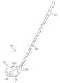
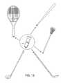
- FIG. 1is an illustrative embodiment of a wood-type golf club structure according to aspects of the disclosure
- FIG. 2is a cartridge according to an illustrative embodiment of the disclosure
- FIGS. 3A and 3Billustrate a monitoring device according to an illustrative embodiment of the disclosure
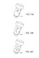
- FIGS. 4A and 4Billustrate a monitoring device according to an illustrative embodiment of the disclosure
- FIG. 4Cis an exploded view of the monitoring device shown in FIGS. 4A and 4B ;
- FIG. 5is a perspective view of another embodiment of a golf club according to an illustrative embodiment of the disclosure, including an exploded view of a grip portion of the golf club having a cartridge supporting a monitoring device;
- FIG. 6is a perspective view of another embodiment of a golf club according to an illustrative embodiment of the disclosure, including an exploded view of a grip portion of the golf club configured to receive a monitoring device;
- FIG. 7is a perspective view of another embodiment of a golf club according to an illustrative embodiment of the disclosure, including an exploded view of a grip portion of the golf club having a monitoring device;
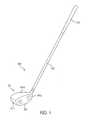
- FIG. 8is an illustrative embodiment of an iron-type golf club structure according to aspects of the disclosure.
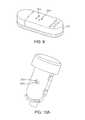
- FIG. 9is an illustrative monitoring device with openings according to aspects of the disclosure.
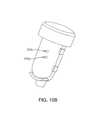
- FIGS. 10A-Bare illustrative removable sections of a golf club according to aspects of the disclosure.
- FIG. 11shows illustrative removable sections of a golf club according to aspects of the disclosure
- FIG. 12shows the illustrative removable sections of FIG. 11 in combination with their respective golf clubs according to aspects of the disclosure
- FIG. 13is illustrates a monitoring device configured to be engaged with various different pieces of sports equipment according to aspects of the disclosure
- FIGS. 14A-Cshow illustrative removable sections of pieces of sports equipment according to aspects of the disclosure
- FIG. 15is an illustrative monitoring device with openings according to aspects of the disclosure configured to be engaged with the removable sections of FIGS. 14A-C ;
- FIG. 16illustrates one embodiment of a golf club including a modified shaft and grip according to aspects of the invention
- FIG. 17illustrates another embodiment of a modified grip and shaft of a golf club according to aspects of the invention.
- FIG. 18illustrates another embodiment of a modified grip and shaft of a golf club according to aspects of the invention.
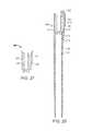
- FIG. 19illustrates another embodiment of a modified shaft of a golf club according to aspects of the invention.
- FIGS. 20 and 21illustrate the shaft of FIG. 19 with different grips connected to the shaft
- FIGS. 22-25illustrate embodiments of monitoring devices and power sources for the monitoring devices, according to aspects of the invention.
- FIG. 26illustrates an exploded view of a grip portion of the golf club having a monitoring device and power source for the monitoring device, according to aspects of the invention
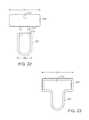
- FIGS. 27-31illustrate one method for assembling a receptacle configured to receive a monitoring device and a grip configured to receive a shaft;
- FIG. 32is a perspective view of the embodiment of a receptacle and grip shown in FIG. 31 according to an illustrative embodiment of the disclosure
- FIG. 33is a rear view of the cartridge of FIG. 5 , having flexible members disposed thereon;
- FIG. 34is an exploded view of the grip portion and monitoring device of FIG. 34 , having flexible members disposed thereon.
- Golf club shaftsmay include: (a) a grip portion; and (b) a removable section which may include a monitoring device.
- the monitoring devicemay also include: (c) one or more sensors and/or (d) a transmitter for transmitting data obtained by the one or more sensors.
- the grip portion or other portion of the shaftmay be configured to receive the removable section.
- the golf club shafte.g., the grip portion
- the golf club shaftmay be configured to receive the monitoring device directly, without a removable section.
- Golf club shafts of at least some example aspects of this disclosuremay include metal shafts, carbon fiber shafts, etc. and be directed to any type of golf club, including wood-type golf clubs, iron-type golf clubs, putter type golf clubs, etc.
- golf club structuresthat include golf club shafts, e.g., of the types described above.
- Such golf club structuresfurther may include one or more of: a shaft attached to the golf club head (optionally via a shaft engaging member (e.g., a hosel) or directly inserted otherwise engaged with the shaft); a grip or handle attached to the shaft; etc.
- Still additional aspects of this disclosurerelate to methods for producing golf club structures in accordance with examples of this disclosure.
- Such methodsmay include, for example, one or more of the following steps in any desired order and/or combinations: (a) providing a golf club head e.g., by manufacturing or otherwise constructing the golf club head body, by obtaining it from a third party source, etc.; (b) engaging a shaft of the various types described above (including any or all of the various structures, features, and/or arrangements described above) with the golf club head; and (c) engaging a grip of the various types described above (including any or all of the various structures, features, and/or arrangements described above) with the shaft.
- the monitoring devicemay include one or more sensors for monitoring data related to aspects of a golfer's golf game (such as the golfer's golf swing) and a transmitter configured to transmit such data. It is further understood that the data may be further processed if necessary or desired. According to aspects of the disclosure, the transmitted data may be analyzed (as will be described in below) and used to aid a golfer in improving the golfer's abilities (e.g., the golfer's golf swing).
- the golf clubsuch that the monitoring device is able to be removable from the golf club.
- the monitoring deviceis able to be removable from the golf club.
- a golf clubconfigured to allow the monitoring device to be easily engageable with, and removable from, the golf club in order to allow the golfer to selectively configure the golf club to their particular preference at a given time.
- the cartridge with monitoring devicecould be removed from the club and replaced with a replacement member without a monitoring device wherein the monitoring device had characteristics such as weighting and aerodynamic features so as to not change the overall characteristics of the golf club from when the monitoring device was installed on the golf club.
- aspects of the disclosureare directed to a golf club which is configured to receive and secure the monitoring device, and is also configured to release the monitoring device.
- aspects of the disclosurerelate to a golf club which includes a golf club shaft which is configured to receive and secure the monitoring device in the golf club shaft.
- the grip of the golf club shaftmay be configured to receive and secure the monitoring device in the grip of the golf club shaft.
- example embodiments of the disclosurerelate to a golf club shaft configured to receive and secure a removable section or a cartridge (e.g., a cartridge containing the monitoring device).
- FIG. 1generally illustrates an example of a wood-type golf club 100 according to aspects of the disclosure.
- the wood-type golf clubmay include a wood-type golf club head 101 in accordance with the present disclosure.
- the overall golf club structure 100may include a shaft 103 and a grip or handle 105 attached to the shaft 103 .
- the shaft 103may be received in, engaged with, and/or attached to the golf club head 101 in any suitable or desired manner, including in conventional manners known and used in the art, without departing from the disclosure.
- the shaft 103may be engaged with the golf club head 101 through a shaft-receiving sleeve or element extending into the club head 101 (e.g., a hosel), and/or directly to the club head structure 101 , e.g., via adhesives, cements, welding, soldering, mechanical connectors (such as threads, retaining elements, or the like).
- the shaft 103may be connected to the golf club head 101 in a releasable manner using mechanical connectors to allow easy interchange of one shaft for another on the head.
- the shaft 103may be made from any suitable or desired materials, including conventional materials known and used in the art, such as graphite based materials, composite or other non-metal materials, steel materials (including stainless steel), aluminum materials, other metal alloy materials, polymeric materials, combinations of various materials, and the like.
- the grip or handle 105may be attached to, engaged with, and/or extend from the shaft 103 in any suitable or desired manner, including in conventional manners known and used in the art, e.g., using adhesives or cements, etc. As another example, if desired, the grip or handle 105 may be integrally formed as a unitary, one-piece construction with the shaft 103 . Additionally, any desired grip or handle materials may be used without departing from this disclosure, including, for example: rubber materials, leather materials, rubber or other materials including cord or other fabric material embedded therein, polymeric materials, and the like.
- the golf club 100may include a hosel.
- the shaft 103may be received in and/or inserted into and/or through the hosel.
- the hoselmay be configured such that the shaft 103 may be engaged with the hosel in a releasable manner using mechanical connectors to allow easy interchange of one shaft for another on the head.
- threads, locking mechanisms, etc.may be incorporated into the hosel and the end of the shaft 103 that is to be engaged with the hosel may be configured with a corresponding configuration.
- the shaft 103may be secured to the hosel via bonding with adhesives or cements, welding (e.g., laser welding), soldering, brazing, or other fusing techniques, etc. Further, optionally, if desired, the hosel may be eliminated and the shaft 103 may be directly attached to the golf club head 101 . For example, the shaft 103 may be directly engaged with the golf club head 101 (e.g., by bonding with adhesives or cements, welding (e.g., laser welding), soldering, brazing, or other fusing techniques, etc.).
- the golf club head 101may include a ball striking face (e.g., a ball striking face which includes a face plate) 107 .
- the ball striking face 107may be provided integrally with the golf club head 101 .
- the ball striking face 107may include a separate element, such as a face plate, which is configured to be engaged with the golf club head.
- the golf club headmay include a structure, such as a recess, notch or other configuration for receiving the face plate.
- the face platemay be engaged with the golf club head in a variety of ways.
- the face platemay be engaged with the golf club head by press fitting, bonding with adhesives or cements, welding (e.g., laser welding), soldering, brazing, or other fusing techniques, mechanical connectors, etc.
- the ball striking face 107may be comprised of one or more materials.
- the material(s) of the ball striking faceshould be relatively durable to withstand the repeated impacts with the golf ball.
- the ball striking face 107may comprise a high strength steel.
- other materials, such as titanium or other metals or alloysmay be used as well.
- the ball striking face 107may include one or more score lines which extend generally horizontally across the ball striking face 107 .
- the golf club headmay include a crown 101 a , a sole 101 b , a toe 01 c , and a heel 101 d .
- the golf club head 101may be constructed in any suitable or desired manner and/or from any suitable or desired materials without departing from this disclosure, including from conventional materials and/or in conventional manners known and used in the art.
- wide varieties of overall club head constructionsare possible without departing from this disclosure.
- some or all of the various individual parts of the club head body described abovemay be made from multiple pieces that are connected together (e.g., by adhesives or cements; by welding, soldering, brazing, or other fusing techniques; by mechanical connectors; etc.).
- the various partsmay be made from any desired materials and combinations of different materials, including materials that are conventionally known and used in the art, such as metal materials, including lightweight metal materials (e.g., titanium, titanium alloys, aluminum, aluminum alloys, magnesium, magnesium alloys, etc.), composite materials, polymer materials, etc.
- the club head 101 and/or its various partsmay be made by forging, casting, molding, machining, and/or using other techniques and processes, including techniques and processes that are conventional and known in the art.
- aspects of the disclosureare directed to a golf club which is configured to receive interchangeable sections or cartridges, wherein one of the interchangeable cartridges may house one or more sensors and/or a transmitter and a second of the interchangeable cartridges does not house a sensor and/or a transmitter, and may house one or more additional components.
- the golfermay selectively configure the golf club to include, or not include, the one or more sensors and/or the transmitter, at the golfer's discretion.
- the monitoring device 201may be configured to measure a multitude of different aspects of a golfer's golf game.
- the monitoring device 201may be configured to measure golf swing data.
- golf swing datamay include information on a variety of different characteristics of a golf swing.
- the monitoring device 201may also be configured to identify the particular golf club in which the sensor is positioned.
- an RFID tagmay be used.
- the monitoring device 201may also be configured to identify a location where a particular golf swing was taken.
- the monitoring device 201may include Global Positioning Satellite (GPS) technology. Such information may be incorporated with maps of the golf course on which the golf shots were taken in order to provide a golfer with information on each shot during a round of golf.
- FIG. 2illustrates one example of a monitoring device 201 that may be employed according to various examples of the disclosure to measure various aspects of a golfer's abilities and game.
- the monitoring device 201may include a processor 204 for processing the electrical signals output by the sensors 202 .
- the processor 204may be a programmable microprocessor.
- the processor 204may be a purpose-specific circuit device, such as an ASIC.
- the processor 204may be configured to perform any desired operation on the signals output from the sensors 202 , such as curve smoothing, noise filtering, outlier removal, amplification, summation, integration, or the like.
- the processor 204may be configured to provide the processed signals to transmitter 203 (or transceiver). Further, the monitoring device 201 may be configured to transmit the processed signals to a remote computer system 400 via the transmitter 203 (or transceiver), as will be discussed below. In one exemplary embodiment, the processed data may be transmitted wirelessly.
- the monitoring device 201may also include a power supply 206 , for providing power to the sensors 202 , the processor 204 , and the transmitter 203 (or transceiver) as needed.
- the power supply 206may be, for example, a battery. Further, as discussed below, embodiments of the monitoring device 201 may include a memory (e.g., a flash memory).
- the memorymay include both a read-only memory (ROM) and a random access memory (RAM). As will be appreciated by those of ordinary skill in the art, both the read-only memory (ROM) and the random access memory (RAM) may store software instructions for execution by the processor 204 .
- ROMread-only memory
- RAMrandom access memory
- the monitoring device 201does not need to include a processor to process the data from the sensors 202 .
- the “raw” data from the sensors 202may be transmitted, such as by wireless transmission, without being processed.
- the monitoring device 201may be configured to measure golf swing data.
- golf swing datamay include, the velocity of the golf club (or club head) during a golf swing, the acceleration of the club (or club head) during a golf swing, the angle of the golf club (or club head) during a golf swing (e.g., relative to one or more reference points), swing tempo, the impact of the ball with the golf club head during a golf swing, aspects of the impact of the ball with the golf club head during a golf swing (e.g., loft, etc.), etc.
- the sensorsmay be configured to measure the position (e.g.
- a spatial position with regard to a particular frame of referenceof the golf club at various points in time in order to provide data on a golf swing.
- acceleration, velocity, positioning of the golf clubmay be determined and analyzed in 3 dimensions.
- some or all of the above datamay be leveraged to create a graphical representation (e.g., a picture or video) of the golf swing.
- a swing pathmay be graphically represented in 3 dimensions along an X-Y-Z frame of reference.
- areas of the “3D golf swing” during which acceleration is taking placemay be represented differently than areas of constant velocity or deceleration. For example, high acceleration takes place may be shown in red, while areas in the swing path during which constant velocity or deceleration takes place may be shown in yellow.
- the monitoring device 201may include one or more sensors 202 .
- the sensors 202may be accelerometers (such as piezoelectric accelerometers), magnetometers, or gyroscopes.
- a monitoring device 201may include an Inertial Measuring Unit (IMU) which includes one or more sensors (e.g., accelerometers and/or gyroscopes, or some combination thereof in an exemplary embodiment) that are configured to measure velocity, acceleration, orientation, gravitational forces, etc.
- IMUInertial Measuring Unit
- sensorse.g., accelerometers and/or gyroscopes, or some combination thereof in an exemplary embodiment
- numerous additional sensorsmay be used in connection with aspects of the disclosure (e.g., impact sensors, strain gauges, etc.).
- the sensors 202may be similar to sensors used in the NIKE+TM athletic performance monitoring systems available from NIKE, Inc. of Beaverton, Oreg.
- the sensors 202may measure golf swing data in a manner akin to the measurement of data in NIKE+TM athletic performance monitoring systems (e.g., speed information, such as velocity and acceleration information, etc.).
- the sensors 202will produce electrical signals corresponding to the specific golfing characteristic it is monitoring. As known in the art, these signals can then be used to generate data representative of the golfing activity performed by the golfer.
- FIGS. 3A and 3Billustrate a particular embodiment of a monitoring device 201 according to aspects of the disclosure.
- the monitoring device 201may include a generally rectangular compartment in which sensors 202 are housed.
- the compartmentmay be similar to the compartment used to house sensors used in the NIKE+TM athletic performance monitoring systems available from NIKE, Inc. of Beaverton, Oreg.
- the compartmentmay be rectangular with rounded ends and has a length in the range of 1.0-1.5 inches, a width of 0.4-1.0 inches and thickness of 0.2-0.45 inches. Other dimensions may be used as well.
- the monitoring device 201 illustrated in FIGS. 4A-Cmay include a transmitter 203 (or transceiver) for wirelessly transmitting data determined by the three accelerometers, three gyroscopes and a magnetometer.
- the compartment of the monitoring device 201may be made of plastic. It is noted that other materials may be used as well.
- the compartment of the monitoring device 201may be opened to provide access to the sensors 202 and the other components housed inside the monitoring device 201 .
- the compartment of the monitoring device 201may include a cover which is configured to slide to provider access to various components of the monitoring device, such as the battery 206 .
- the compartment of the monitoring device 201may house a circuit board or the like which may include various elements described above, such as the processor 204 , sensors 202 , transmitter 203 , power supply 206 , memory, etc.
- FIGS. 4A-Cillustrate a particular embodiment of the monitoring device 201 .
- FIG. 4Ais a perspective view of the monitoring device 201 .
- FIG. 4 Bis a perspective view of the bottom of the monitoring device 201 .
- FIG. 4Cis an exploded view of the monitoring device 201 .
- the monitoring device 201includes a generally rectangular compartment in which sensors 202 are housed. The compartment may be similar to the compartment used to house sensors used in the NIKE+TM athletic performance monitoring systems available from NIKE, Inc. of Beaverton, Oreg. Further, the monitoring device 201 illustrated in FIGS.
- the monitoring device 201 illustrated in FIGS. 4A-Cmay include a transmitter 203 (or transceiver) for wirelessly transmitting data determined by the three accelerometers, three gyroscopes and a magnetometer.
- the compartment of the monitoring device 201may be made of plastic. It is noted that other materials may be used as well. As seen in FIG. 4C , the compartment of the monitoring device 201 may be opened to provide access to the sensors 202 and the other components housed inside the monitoring device 201 . For example, as seen in FIG. 4B , the compartment of the monitoring device 201 may include a locking mechanism which allows the compartment to be unlocked and opened. As seen in FIG. 4C , the compartment of the monitoring device 201 may house a circuit board or the like which may include various elements described above, such as the processor 204 , sensors 202 , transmitter 203 , power supply 206 , memory, etc.
- the monitoring device 201may include an activation system.
- the activation systemmay be used for selectively activating the monitoring device 201 and/or at least some functions of the monitoring device 201 (e.g., data transmission/reception functions, data storage functions, data calculation functions, etc.).
- functions of the monitoring device 201e.g., data transmission/reception functions, data storage functions, data calculation functions, etc.
- a wide variety of different activation systemsmay be used without departing from this disclosure.
- input from the activation systemmay be provided in any desired form or format without departing from the disclosure.
- the activation systemmay include a simple button, switch, or other input source that simply provides an activation or deactivation signal to the monitoring device 201 (e.g., a logical “1” or “0”).
- the activation systemmay activate the monitoring device 201 , based on input it receives from the remote computer 400 (described below). For example a golfer may manually activate the monitoring device 201 by providing input (e.g., pressing a button) on the remote computer 400 . Alternatively, the activation system may activate the monitoring device 201 automatically upon a certain action being performed.
- the activation systemmay induce the monitoring device 201 or its functions to operate.
- the monitoring device 201includes an accelerometer and the golfer waggles the club (e.g., moves the club) over a predefined speed or length of time
- the activation systemmay automatically activate the monitoring device 201 and/or at least some functions of the monitoring device 201 (e.g., data transmission/reception functions, data storage functions, data calculation functions, etc.).
- the activation systemmay activate the monitoring device 201 when the golf club expands on impact (e.g., an impact with a golf ball).
- a monitoring device 201may be configured to enter a sleep mode to conserve battery power if the monitoring device 201 is not used for a predetermined amount of time.
- one of the sensors 202may be an accelerometer.
- An accelerometeris a device used to measure acceleration.
- an accelerometermay measure the magnitude and the direction of acceleration.
- An accelerometer according to aspects of the disclosuremay include a three-axis accelerometer for measuring acceleration along three orthogonal axes.
- one or more accelerometersmay be included in the golf club 100 .
- one or more accelerometersmay be included in the monitoring device 201 or other a micro-electromechanical system (MEMS) configured to be engaged within the golf club shaft 103 /grip 105 .
- MEMSmicro-electromechanical system
- the accelerometermay be configured to measure the velocity of the golf club 100 (e.g., club head 101 , shaft 103 , grip 105 ) during a golf swing, the acceleration of the club 100 (e.g., club head 101 , shaft 103 , grip 105 ) during a golf swing, etc.
- one of the sensors 202may be a magnetometer.
- a magnetometeris an instrument used to measure the strength and or the direction of a magnetic field around the instrument.
- one or more magnetometersmay be included in the golf club 100 .
- one or more magnetometersmay be included in the monitoring device 201 or other MEMS configured to be engaged within the golf club shaft 103 /grip 105 .
- one or more magnetometersmay also be used to determine golf swing parameters, e.g., using techniques incorporating the Earth's magnetic field as a reference, as shown and described in incorporated U.S. Provisional Application Ser. No. 61/665,834.
- one of the sensors 202may be a gyroscope.
- a gyroscopeis a device used to measure orientation and rotation.
- a gyroscopemay measure orientation based on the principles of the conservation of angular momentum.
- a three-axis gyroscopemay be used to increase accuracy.
- the combination of the gyroscope and the accelerometermay provide a more accurate indication of movement within a 3-D space when compare to an accelerometer alone.
- one or more gyroscopesmay be included in the golf club 100 .
- one or more gyroscopesmay be included in the monitoring device 201 or other MEMS configured to be engaged within the golf club shaft 103 /grip 105 .
- the gyroscope 320may be configured to determine golf swing parameters using techniques as shown and described in incorporated U.S. Provisional Application Ser. No. 61/665,834.
- the gyroscope 320may be used to determine: (1) the face angle of golf club head 101 , e.g., as a function of the shaft rotation rate, (2) the club head speed, e.g., as a function of the radius (arm length plus club length) and angular velocity, (3) swing tempo, e.g., based on the angular velocity, (4) time of impact, e.g., based on the angular velocity, and/or (5) swing path, e.g., based on the rotational velocity, among other parameters.
- data from other sensorse.g., accelerometer, impact sensor, etc.
- data from any of the sensors described abovemay be combined to make the determinations described herein.
- the monitoring devicecan determine various aspects of a golfer's golf swing, including: the velocity of the golf club (or club head) during a golf swing, the acceleration of the club (or club head) during a golf swing, the angle of the golf club (or club head) during a golf swing (e.g., relative to one or more reference points), swing tempo, the impact of the ball with the golf club head during a golf swing, etc.
- the golf club 100may include a transmitter 203 .
- the transmitter 203may be a transceiver which is capable of receiving data as well as transmitting data. Data determined from each of the one or more sensors 202 may be communicated to the transmitter 203 .
- the one or more sensors 202may be electrically connected to transmitter 203 .
- datamay be communicated wirelessly from the one or more sensors 201 to the transmitter 203 .
- the transmitter 203may be configured to transmit the data determined by the one or more sensors 202 to a remote computer system 400 (e.g., a portable computer device with a receiver configured to receive the data from the transmitter 203 ).
- a remote computer system 400e.g., a portable computer device with a receiver configured to receive the data from the transmitter 203 .
- the monitoring device 201may include a memory.
- the memorymay be configured to store data from the one or more sensors 202 . More specifically, the memory may store data while the golfing activity takes place and save it for later transmission to the remote computer system 400 (as discussed below).
- the transmitter 203may be configured to transmit data using a variety of conventional protocols.
- the monitoring device 201may be configured to communicate using the Bluetooth wireless communication protocol, so that it can be employed with Bluetooth-capable mobile telephones, personal digital assistants, watches or personal computers. Further, other methods of transmitting may be used as well, such as Bluetooth2, RFID, infrared transmission, cellular transmissions, etc.
- the transmitter 203may be configured to transmit data via an antenna.
- a ferruleis used as an antenna.
- the ferrulemay be formed of a metal material or other type of antenna material.
- shaft 103may function as an antenna.
- An antennamay also be plated onto shaft 103 , embedded under grip 105 or placed in any other location that does not interfere with a golf swing.
- the monitoring device 201 and the golf club head 101may be configured such that a connection is made between the transmitter 203 and the antenna when the monitoring device 201 is engaged with the golf club head 101 .
- monitoring device 201may include its own data storage system for storing data from the one or more sensors 202 . Further, the monitoring device 201 may be configured to be engaged with the remote computer system 400 in order to transmit data to the remote computer 400 .
- monitoring device 201may include an interface (e.g., a USB connection) configured to engage with a port of the remote computer system 400 in order to transmit data to the remote computer 400 .
- data collected from the sensors 202may be stored during a practice session or a round of golf. Then, at a convenient time, such as after the practice session or round of golf, the golfer may disengage the monitoring device 201 from the golf club head and engage it with the remote computer system 400 in order to transmit the data to the remote computer system 400 .
- Any type of connection systemmay be used without departing from the scope of the disclosure, including a wireless connection, a hardwired connection, connection via an input port (such as a USB port, or the like), etc.
- the monitoring device 201may include a receiver (e.g., the transmitter 203 may be a transceiver) which determines whether a transmission from transmitter 203 has been or is being received by the remote computer 400 . If the transmission from transmitter 203 is not received by the remote computer 400 , the monitoring device 201 may be configured to store the data on the memory (e.g., if the remote computer system 400 is not in range or is turned off).
- a receivere.g., the transmitter 203 may be a transceiver
- the monitoring device 201may be configured to transmit data to the remote computer system 400 (e.g., a portable computer system, such as a cellular telephone) and the remote computer system 400 may be configured to transmit data to a secondary computer system (such as a desktop computer) or a network, such as through a wired or wireless connection.
- the remote computer system 400e.g., a portable computer system, such as a cellular telephone
- a secondary computer systemsuch as a desktop computer
- a networksuch as through a wired or wireless connection.
- the remote computer system 400could be used during play (e.g., at a practice session on a driving range or on the course during play) to give real time feedback to the golfer (e.g., during the round or practice session). Thereafter or in real-time, the data from the portable remote computer system 400 may be downloaded or uploaded to the secondary computer system for further analysis, storage, comparison, reference, presentation, etc., as shown and described in incorporated U.S. Provisional Application No. 61/665,834.
- the remote computer system 400may be any desired type of computer system, at any desired location, without departing from the scope of the disclosure.
- the remote computer system 400may be, for example, portable audio and/or video players, cellular telephones, personal digital assistants, pagers, beepers, palm top computers, laptop computers, desktop computers, servers, or any type of computer controlled device, optionally a computer controlled device that generates or displays a human perceptible output and/or interface.
- processor systemwhich may include one or more processors or microprocessors, which may be configured to execute software instructions
- memorywhich may include RAM and ROM and may be configured to store various software instructions for execution by the processor system
- output devicee.g., visual and/or audio output
- power supplye.g., a power supply
- other user input devicese.g., a power supply
- a data transmission/reception systeme.g., a wireless receiver or transceiver
- the processor systemmay be configured to process the data/signals from the monitoring device 201 in various manners.
- the above described monitoring system(which includes the monitoring device 201 and the remote computer system 400 ) may be configured to be active, real-time transmitting systems that provides data to the remote computer system 400 as the golf activity is taking place.
- the remote computer system 400may be configured to provide the golfer with real-time performance feedback (e.g., velocity of the golf club head, acceleration of the golf club head, the impact position of the golf ball on the ball striking face, path of the swing path of a particular swing, face angle of the ball striking face of the club head throughout the swing (e.g., during impact), etc.) while the golfing performance is taking place as shown and described in incorporated U.S. Provisional Application Ser. No. 61/665,834.
- the monitoring device 201 and/or the computer system 400may further include or be usable with any other component, feature, and/or function described in incorporated U.S. Provisional Application No. 61/665,834, in various embodiments, including without limitation: (1) strain gauges may be used in conjunction with the monitoring device 201 in order to provide measurements regarding the axial strain, bending moments or other characteristics of the shaft 103 or other features of the golf swing; (2) the monitoring device 201 may be configured to identify the particular golf club in which the monitoring device 201 is engaged, e.g., by using an RFID or other chip, by utilizing protrusions as described below, by using data collected on “practice” swings, etc.; (3) the monitoring device 201 and/or the computer system 400 may coordinate one or more characteristics of a particular golf shot with the identity of the particular golf club with which the shot was made, and such identity may also be utilized in calculating parameters (e.g., estimated shot distance) of the golf shot; (4) the monitoring device 201 may be “universal” with respect to all golf clubs
- data collected from the above described system and metrics determined by the above described systemmay be uploaded to a network for further processing.
- the remote computer 400itself may be configured to compare the data and metrics with a predefined set of characteristics for further processing.
- the shaft 103 and/or the grip 105may be configured to receive a removable section or cartridge 200 . Further, the removable section 200 may be configured to receive the monitoring device 201 .
- FIG. 5shows an illustrative embodiment of such aspects of the disclosure.
- the removable section 200may include a circular portion which forms the top of the shaft and, also, an elongated portion configured to house the monitoring device 201 .
- the elongated portion of the removable section 200may include guides to aid in positioning and securing the monitoring device 201 within the removable section 200 . It is noted that the removable section 200 may be configured to secure the monitoring device 201 in such a way that the monitoring device 201 does not move within the removable section 200 .
- the removable section 200may be configured to engage with the monitoring device 201 (e.g., a compartment which includes the exterior of the monitoring device 201 ) via press fitting, snap fit mechanisms (e.g., spring loaded protrusions and corresponding detents), mechanical fasteners, etc.
- the elongated portionmay include a first arched end configured to engage a first rounded end of the compartment, a second arched end configured to engage a second rounded end of the compartment and a back portion which extends between the first arched portion and the second arched portion and is configured to engage a side of the compartment.
- the removable section 200may be configured to support and stabilize the monitoring device 201 .
- the elongated portionmay be configured to secure the compartment which may be rectangular with first and second rounded ends and have a length in the range of 1.0-1.5 inches, a width of 0.4-1.0 inches and thickness of 0.2-0.45 inches.
- the removable section 200may be made of plastic. It is noted that other materials, such as rubber, or combinations thereof may be used as well.
- the removable section or cartridge 200may be configured to be engaged with the grip 105 in a variety of ways.
- the grip 105may be configured with an opening at its terminal end that is configured to receive the removable section 200 .
- the grip 105may be configured with guides within the interior of the grip 105 that guide the removable section during insertion into the grip 105 .
- the gripmay be configured with a locking mechanism, such as threads which line the interior of the grip 105 .
- the removable section 200may include a corresponding structure through which the removable section 200 is engaged and locked with the grip 105 upon twisting the removable section 200 into the grip 105 .
- the removable section 200may be configured to engage with the grip 105 via press fitting, snap fit mechanisms (e.g., spring loaded protrusions and corresponding detents), mechanical fasteners, etc.
- the removable section 200may have flexible members 221 positioned on the clip 207 that holds the monitoring device 201 .
- the flexible members 221are configured to engage the interior of the grip 105 and/or shaft 103 to retain the removable section 200 and the monitoring device 201 in place inside the grip 105 .
- the flexible members 221are in the form of ridges that partially encircle the base 209 of the clip member 207 , but may be configured differently in other embodiments.
- the flexible members 221may be configured as ridges that completely encircle a component, or may be configured as bumps or tabs on the exterior surface. In one embodiment, the flexible members 221 may be positioned at least on the areas of the removable section 200 that have the maximum dimension perpendicular to the direction of insertion into the grip 105 /shaft 103 .
- the flexible members 221allow the removable cartridge 200 to be inserted into multiple grips having varying shaft diameters. This further allows the removable cartridge 200 to be used in different clubs or other sporting equipment. It is understood that other embodiments of removable cartridges 200 shown and described herein may include flexible members 221 for these purposes, including the removable cartridges illustrated in FIGS. 6 , 10 A- 15 , and 30 - 32 .
- the flexible members 221can be formed from a variety of materials known in the art, including rubber or polyurethane.
- one or more fastenersmay be used to retain the cartridge 200 within the shaft 103 , including the configuration described below and shown in FIG. 6 or other configurations.
- FIG. 6illustrates an exploded view of another embodiment of a removable section or cartridge according to aspects of the disclosure.
- the cartridge 200may be configured to fit within a top portion of the grip 105 , or distal end of the grip 105 .
- the top portion of the grip 105may include a first portion which is configured to receive the cartridge supporting the monitoring device 201 and a second portion configured to engage with the interior of the shaft 103 of the golf club.
- the top portion of the grip 105may be configured to removably fit within the golf club shaft 103 .
- the removable top portion of the grip 105 and the cartridge 200may be configured to be attached to each other as explained below.
- the top portion of the grip 105may be considered a cartridge holder or a component receptacle 106 .
- the cartridge holder 106defines a housing which is configured to receive components such as the monitoring device 201 , the power source 206 , and/or other components.
- the cartridge holder 106generally includes a first portion 108 which is configured to receive the cartridge 200 supporting the monitoring device 201 and a second portion 110 configured to engage with the shaft 103 of the golf club.
- the first portion 108has a main body portion 190 having a first opening 191 therein and a second opening 192 .
- the first opening 191is generally an elongated slot that extends generally longitudinally into the main body portion 190 .
- the first opening 191can vary in length and width and is generally dimensioned to receive the portion of the cartridge 200 holding the monitoring device 201 as described in greater detail below.
- the first opening 191is dimensioned such that there minimum play between the cartridge 200 and the main body portion 190 , in one embodiment.
- the second opening 192includes a connecting structure, such as threading, in an exemplary embodiment.
- the main body portion 190further defines a recessed portion 193 at a distal end, and the first opening 191 and the second opening 192 open at the recessed portion 193 .
- the second portion 110is configured for engaging the shaft 103 , and in the embodiment of FIG. 6 , has a protrusion 194 that extends from the main body portion 190 of the first portion 108 .
- the protrusion 194may be hollow and is dimensioned to fit within and extend into the shaft 103 .
- the protrusion 194may engage the shaft 103 in another manner in other embodiments, or the cartridge holder 106 may include a different engaging structure.
- the cartridge holder 106is an integral member and can be formed from a variety of materials known in the art.
- an outer surface of the main body portion 190may be formed with the material identical to the remaining portions of the grip member to provide a uniform surface as desired.
- the removable cartridge 200has a cap member 205 having a clip member 207 depending from the cap member 205 .
- the cap member 205has an orifice 208 extending therethrough and adjacent to the clip member 207 .
- the clip member 207has a base 209 and a resilient finger 210 extending generally transversely from the base 209 at the end opposite the cap member 205 .
- the base 209is dimensioned to accommodate the length of the monitoring device 201 .
- the resilient finger 210engages an end of the sensor 201 .
- One end of the monitoring device 201is engaged by the resilient finger 210 and another end of the monitoring device 201 is engaged by an underside of the cap member 205 . Accordingly, the monitoring device 201 can be snapped into the clip member 207 .
- additional fingers or other retaining elementscan be incorporated with the clip member 207 , and the cartridge 200 and the monitoring device 201 may include complementary engaging structure, such as tabs and slots.
- additional retaining elementsmay be employed when a longer base 209 is utilized thus spacing the sensor 201 further away from the cap member 205 .
- the cartridge holder 106is secured to the shaft 103 .
- the second portion 110is inserted and secured to the shaft 103 .
- This connectionmay be a permanent connection or a releasable connection.
- the removable cartridge 200is inserted into the cartridge holder 106 .
- the base 209 and finger 210 holding the monitoring device 201are inserted into the first opening 191 .
- the structure of the main body portion 190surrounds and securely holds the cartridge 200 and thereby further protects the monitoring device 201 from damage due to impact or the elements.
- the first opening 191is generally non-circular wherein the clip member 207 holding the sensor 201 must be inserted into the first opening 191 in a set, fixed orientation. Further, with minimum play around the monitoring device 201 , the position of the monitoring device 201 is always known. This aids in the ability to record and analyze data in a desired fashion.
- the cartridge 200 and the top portion of the grip 105may be configured to be fastened together by a threaded fastener 211 or other connection member.
- the cap member 205is received in the recessed portion 193 .
- the cap member 205is generally flush with the end of the cartridge holder 106 .
- the orifice 208 on the cap member 205is aligned with the second opening 192 .
- a threaded fastener 211is inserted through the orifice 208 and secured in the second opening 192 by threadable engagement.
- the second opening 192may contain a threaded insert 195 to establish such engagement, as in the embodiment of FIG. 6 , or may include integral threading or another connecting structure in another embodiment.
- removable cartridge 200is thus secured in the grip of the club by a single fastener.
- other fastening mechanismscould be utilized between the removable cartridge 200 and the cartridge holder 106 , or otherwise the grip 105 .
- the other fastening mechanismsinclude snap-fitting configurations or interference fittings as well as other mechanical configurations.
- the cartridge holder 106 holding the cartridge 200is seamlessly integrated into the grip 105 and is virtually undetectable.
- the golf clubappears like any traditional golf club that does not incorporate any sensor technology.
- the first portion of the grip 105 configured to receive the cartridge supporting the monitoring device 201may be configured to surround and securely hold the cartridge 200 and thereby further protect the monitoring device 201 from damage due to impact or the elements.
- the removable cartridge 200may utilize features of other embodiments described herein.
- the clip member 207may have different lengths such as shown in FIG. 11 .
- the cartridge holder 106may then have corresponding structure to cooperate with a cartridge 200 with such dimensions.
- the cartridge 200may also employ the various lock-out or other identifying structures described herein.
- the grip 105may be configured to receive and secure the monitoring device 201 directly, without the inclusion of a separate removable section or cartridge 200 .
- FIG. 7shows an illustrative embodiment of such aspects of the disclosure.
- the monitoring device 201may be configured to be engaged with the grip 105 in a variety of ways.
- the grip 105may be configured with an opening at its terminal end that is configured to receive the monitoring device 201 .
- the grip 105may include a slit that is configured to receive the monitoring device 201 when the monitoring device 201 is inserted into the grip 105 along the monitoring device's longitudinal axis.
- the slitmay be configured to provide a tight interference fit with the monitoring device 201 .
- the grip 105may be configured to secure the monitoring device 201 such that the monitoring device 201 does not move within the grip 105 .
- the removable section 200may be configured to support and stabilize to the monitoring device 201 .
- the grip 105may be configured with guides within the interior of the grip 105 that guide the monitoring device 201 during insertion into the grip 105 .
- the gripmay be configured with a locking mechanism, such as a cover which includes flaps through which the monitoring device is inserted.
- monitoring device 201may be configured to engage with the grip 105 via other methods as well, including snap fit mechanisms (e.g., spring loaded protrusions and corresponding detents), other mechanical fasteners, etc.
- the shaft 103may be configured to receive the monitoring device 201 and/or the removable section 200 at the fixed end of the shaft 103 , proximate the head. Further, the interior of the shaft 103 may be configured to position the monitoring device 201 at any point along the length of the shaft 103 (e.g., at the fixed end, the butt/grip end, the center, etc.).
- the grip/butt end of the shaft 103may be removable to allow the monitoring device 201 to be inserted, such as shown in FIG. 18 and described in greater detail below.
- the fixed end of the shaftmay be removably engaged with the golf club head 101 .
- the monitoring device 201may be inserted into that end of the shaft 103 as well.
- more than one monitoring device 201may be inserted into the shaft 103 in order to measure various different locations or different portions of the shaft 103 during the golf swing.
- golf club 101may include a monitoring device 201 in both the shaft 103 and in the golf club head 101 .
- the golf club 101may include two monitoring devices 201 , such as a first monitoring device 201 which is positioned in the grip 105 (such as shown in FIG. 5 ) and a second monitoring device 201 which is positioned in the golf club head 101 as shown and described in incorporated U.S. Provisional Application Ser. No. 61/665,834.
- a first monitoring device 201may be configured to be a “master” monitoring device 201 and the other monitoring devices 201 may be configured to communicate data to the “master” monitoring device 201 as also shown and described in incorporated U.S. Provisional Application Ser. No. 61/665,834.
- FIG. 8illustrates an example of an iron-type golf club 700 according to aspects of the disclosure.
- the iron-type golf club 700may include an iron-type golf club head 701 in accordance with the present disclosure. It is understood that any aspects described herein may be utilized with a wood-type golf club, an iron-type golf club, or other type of golf club.
- monitoring device 201 and associated mounting structuresmay be utilized with other types of ball striking devices and sporting equipment, such as tennis or other racquets, bats (e.g., baseball, softball, cricket, etc.), hockey sticks (e.g., ice hockey, field hockey), lacrosse sticks, etc., as illustrated in FIG. 13 .
- batse.g., baseball, softball, cricket, etc.
- hockey stickse.g., ice hockey, field hockey
- lacrosse stickse.g., lacrosse sticks, etc.
- the overall golf club structure 700may include a shaft 703 and a grip or handle 705 attached to the shaft 703 .
- the shaft 703may be received in, engaged with, and/or attached to the golf club head 701 in any suitable or desired manner, including in conventional manners known and used in the art, without departing from the disclosure.
- the shaft 703may be engaged with the golf club head 701 through a shaft-receiving sleeve or element extending into the club head 701 (e.g., a hosel), and/or directly to the club head structure 701 , e.g., via adhesives, cements, welding, soldering, mechanical connectors (such as threads, retaining elements, or the like).
- a shaft-receiving sleeve or elementextending into the club head 701 (e.g., a hosel), and/or directly to the club head structure 701 , e.g., via adhesives, cements, welding, soldering, mechanical connectors (such as threads, retaining elements, or the like).
- the shaft 703may be connected to the golf club head 701 in a releasable manner using mechanical connectors to allow easy interchange of one shaft for another on the head.
- the grip or handle 705may be attached to, engaged with, and/or extend from the shaft 703 in any suitable or desired manner, including in conventional manners known and used in the art, e.g., using adhesives or cements, etc.
- the shaft 703 and the grip or handle 705may be made from any suitable materials such as those described above with regard to the wood type golf club 100 .
- the golf club head 701may also include a ball striking face (e.g., a ball striking face which includes a face plate) 711 .
- the golf club head 701may be constructed in any suitable or desired manner and/or from any suitable or desired materials without departing from this disclosure, including from conventional materials and/or in conventional manners known and used in the art.
- the club head 701 and/or its various partsmay be made by forging, casting, molding, and/or using other techniques and processes, including techniques and processes that are conventional and known in the art.
- the golf club head 701may be a blade type iron golf club head.
- the golf club head 701may be a perimeter weighted and/or cavity back type golf club head or other iron type golf club head structure.
- the grips of each of the golf clubs in the set of golf clubsmay be configured to receive the monitoring device 201 in a manner discussed above with regard to FIGS. 5-7 .
- monitoring device 201may be similar to those used in the NIKE+TM athletic performance monitoring systems available from NIKE, Inc. of Beaverton, Oreg.
- the monitoring device 201may include a generally rectangular compartment which may be similar to the compartment used to house sensors used in the NIKE+TM athletic performance monitoring systems available from NIKE, Inc. of Beaverton, Oreg.
- the compartment of the monitoring device 201may house various elements described above, such as the processor 204 , sensors 202 , transmitter 203 , power supply 206 , memory, etc. Further, as described above, according to aspects of the disclosure, the monitoring device 201 may be configured to engage with the grip 105 of the golf club. For example, as described with regard to FIG. 5 , the grip 105 may be configured to receive a removable section or cartridge 200 and the removable section 200 may be configured to receive the monitoring device 201 .
- the engagement between the monitoring device 201 and removable section 200 the particular golf clubmay cause a particular IMU of the monitoring device 201 to be selectively activated.
- the monitoring device 201may include one or more openings 201 o configured to receive one or more protrusions (e.g., prongs) that extend from the removable section 200 of the particular golf club.
- a particular IMU of the monitoring device 201may be activated based on which of the openings in the monitoring device 201 receive a protrusion of the removable section 200 .
- the monitoring device 201may include four openings 201 o .
- a removable section 200 of a putter of the set of golf clubsmay have two protrusions 200 p that are configured to engage with the first and second of the four openings 201 o of monitoring device 201 .
- a first IMU of the monitoring device 201that is configured to measure velocity and/or acceleration associated with a putting stroke (e.g., an IMU that may be extremely sensitive to small changes in velocity and/or acceleration (e.g., fractions of a meter per second or m/s 2 )) may be selected and/or activated.
- a removable section 200 of an iron-type golf club or a wood-type golf club of the set of golf clubsmay have two protrusions that are configured to engage with the third and fourth of the four openings 201 o of monitoring device 201 .
- a second IMU of the monitoring device 201that is configured to measure velocity and/or acceleration associated with a golf swing for the iron-type golf club or the wood-type golf club (e.g., an IMU that may be may be less sensitive to small changes in velocity and/or acceleration (as compared with the first IMU) and able to more accurately determine larger changes in velocity and/or acceleration (e.g., at least several meters per second or m/s 2 )) may be activated.
- the protrusions of the removable section 200may be configured to activate detecting switches within monitoring device 201 which cause the processor 204 to determine which of the IMUs to use.
- IMUsSeveral examples of utilizing IMUs are shown and described in incorporated U.S. Provisional Application Ser. No. 61/665,834.
- the protrusions 200 p and openings 201 omay be arranged such that the monitoring device 201 can only be engaged with the removable section in an intended orientation.
- a “universal” monitoring device 201may have four holes, the protrusions 200 p on the removable section 200 and openings 201 o on the monitoring device 201 are arranged such that they will align only when the monitoring device 201 is engaged with the removable section 200 in the intended orientation.
- the grip 105may be configured to receive and secure the monitoring device 201 directly, without the inclusion of a separate removable section.
- the monitoring device 201may be configured to be engaged with the grip 105 in a variety of ways.
- the grip 105may be configured with an opening at its terminal end that is configured to receive the monitoring device 201 .
- the grip 105itself may be configured with the above discussed protrusions 200 p configured to engage with the openings 201 o in the monitoring device 201 to selectively determine which of the IMUs of the monitoring device 201 to use in capturing data associated with the golf stroke.
- the grip 105may include a slit that is configured to receive the monitoring device 201 when the monitoring device 201 is inserted into the grip along the monitoring device's longitudinal axis.
- one or both of the rounded ends of the compartment of the monitoring device 201may be configured to include the openings 201 o which are configured to receive the protrusions 200 p and the lower end of the slit may include the one or more protrusions 200 p .
- the protrusions 200 pmay positioned on the sides of the slit and may be spring loaded, flexible, etc. in order to accommodate the insertion and removable of the monitoring device 201 .
- openings 201 o and four protrusion 200 pare discussed in the illustrative embodiment, it is clear that any combination of openings 201 o and protrusions 200 p may be used provided the combination will sufficiently allow the monitoring device 201 to selectively determine which of the IMUs of the monitoring device 201 to use in capturing data associated with the golf stroke.
- shape memory alloymay be used as well.
- Shape memory alloyis a substance which is configured to return to its original shape upon heating.
- the structural engagement between the monitoring device 201 and the golf club 100as a means of allowing the monitoring device 201 to selectively determine which of the IMUs of the monitoring device 201 to use in capturing data associated with the golf stroke
- other methods and meansmay be used as well, including an RFID chip or other chip, as discussed elsewhere herein.
- the monitoring device 201may be configured to be charged.
- the monitoring device 201may include a power supply (e.g., a battery). Further, the monitoring device 201 may be configured to receive a charging cable which will provide power to recharge the power supply. In some embodiments, the monitoring device 201 may be configured to receive the charging cable while the monitoring device 201 is in the golf club itself. For example, in embodiments where the monitoring device 201 is positioned in the shaft/grip of the golf club, the end of the golf club may be removed and the charging cable may be hooked into the monitoring device 201 .
- the cartridge 200 as shown in FIGS. 6 and/or 27 - 32may include integral structure to enable charging.
- the monitoring device 201may be configured to be charged via induction charging.
- the monitoring device 201is configured to receive information via a charging cable.
- the charging cablemay be a USB cable which is configured to connect the monitoring device 201 with computer (e.g., the remote computer 400 ) or other data source. Accordingly, during the connected with the computer, the monitoring device 201 can update firmware, reboot the system, and conduct other diagnostic checks and updates as needed or instructed.
- the removable section 200may include a circular portion which forms the top of the shaft and, also, an elongated portion configured to house the monitoring device 201 .
- the elongated portion of the removable section 200may include guides to aid in positioning and securing the monitoring device 201 within the removable section 200 . It is noted that the removable section 200 may be configured to secure the monitoring device 201 in such a way that the monitoring device 201 does not move within the removable section 200 .
- the removable section 200may be configured to engage with the monitoring device 201 (e.g., a compartment which includes the exterior of the monitoring device 201 ) via press fitting, snap fit mechanisms (e.g., spring loaded protrusions and corresponding detents), mechanical fasteners, etc.
- the elongated portionmay include a first arched end configured to engage a first rounded end of the compartment, a second arched end configured to engage a second rounded end of the compartment and a back portion which extends between the first arched portion and the second arched portion and is configured to engage a side of the compartment.
- the removable section 200may be configured to support and stabilize the monitoring device 201 .
- the elongated portionmay be configured to secure the compartment which may be rectangular with first and second rounded ends and have a length in the range of 1.0-1.5 inches, a width of 0.4-1.0 inches and thickness of 0.2-0.45 inches.
- the elongated portion of the removable section 200may be configured to have a particular length such that when the removable section 200 is engaged with the grip of the golf club, the removable section 200 positions the monitoring device 201 within the shaft 103 such that the monitoring device 201 is offset by a specified distance from a reference point.
- the elongated portion of the removable section 200may include the first arched end configured to engage a first rounded end of the compartment, the second arched end configured to engage a second rounded end of the compartment and the back portion which extends between the first arched portion and the second arched portion and is configured to engage a side of the compartment, but the first arched end, second arched end and back portion are spaced further away from the round portion of the removable section which forms the end cap.
- the first arched end, second arched end and back portionmay be spaced from the round portion by a section of the elongated portion that extends between the round portion and the upper arched end of the guide for receiving the monitoring device.
- the section of the elongated portion that extends between the round portion and the upper arched end of the guidemay be a particular length such that when the removable section 200 is engaged with the shaft, of the golf club, the removable section 200 positions the monitoring device 201 within the shaft such that the monitoring device 201 is offset by a specified distance from a reference point.
- the removable section 200 associated with each of the respective, different golf clubs in the setmay have to be configured differently in order to ensure the that the respective monitoring device 201 is positioned within the shaft, such that the monitoring device 201 is offset by a specified distance from a reference point.
- the length of the section of the elongated portion that extends between the round portion and the upper arched end of the guidemay be a different for each of the respective removable sections 200 in the golf club set in order to ensure the that the respective monitoring device 201 is positioned within the shaft, such that the monitoring device 201 is offset by a specified distance from a reference point.
- FIG. 11illustrates embodiments of such removable sections 201 .
- a first removable section 200 associated with a first golf club of the set of golf clubsmay have a first elongated portion that has a first length
- a second removable section 200 associated with a second, different golf club of the set of golf clubsmay have a second elongated portion that has a second length which is different (e.g., longer) from the first length.
- a third removable section 200 associated with a third, different golf club of the set of golf clubsmay have a third elongated portion that has a third length, which is different (e.g., longer) than the first or second lengths.
- a shorter clube.g., a pitching wedge
- a longer clube.g., a long iron or hybrid type golf club
- an even longer clube.g., a driver
- each of the golf clubs in the setcould have a removable section 200 with an elongated portion of a different length (e.g., increasing longer as the length of the club increases) in order to position the monitoring device 201 in the correct positioning.
- the removable sections 200may have other structures as well.
- the removable sections 200may be a self-locating, conical structure in which the monitoring device 201 is received.
- the conical structuremay be configured to engage with the interior of the shaft 103 of the golf club 100 in order to position the monitoring device 201 in the appropriate position within the shaft 103 .
- the multitude of conical removable sections 200 for engagement with the different clubs in a set of golf clubsmay be longer and wider (e.g., have an increased diameter) to position the monitoring device 201 in the appropriate position within the shaft 103 .
- the interior of the golf club shaft 103may include a structured (e.g., positioning recesses/protrusions or ledges) which are configured to engage with the removable sections 200 and position the monitoring device 201 in the appropriate position within the shaft 103 .
- a structurede.g., positioning recesses/protrusions or ledges
- each clubmay be configured such that it secures its respective monitoring device 201 at a common point respective to each of the golf clubs in the set (e.g., such that the monitoring device 201 is offset by an identical specified distance from a reference point which is common to each of the golf clubs in the set)
- a removable section 200it is noted that other means may be used as well, such as those described in incorporated U.S. Provisional Application No. 61/665,834.
- FIGS. 14A-Cshow illustrative removable sections 200 according to aspects of this disclosure.
- each of the removable sections 200may include an elongated portion configured to aid in housing the monitoring device 201 .
- each of the elongated portionsmay include a first arched end configured to engage a first rounded end of the compartment, a second arched end configured to engage a second rounded end of the compartment and a back portion which extends between the first arched portion and the second arched portion and is configured to engage a side of the compartment of the monitoring device 201 .
- the elongated portion of each of the removable section 200may include the one or more protrusions 200 p . As seen FIG.
- the illustrative removable section 200 Tincludes a plurality of protrusions 201 p which are arranged in unique positioning. In this case there are five protrusions 200 p arranged in the unique positioning. It is noted that the number of protrusions 200 p and the unique positioning of those protrusions 200 p may be configured such that when engaged with the monitoring device 201 , they indicate to the monitoring device to the piece of sports equipment with which the monitoring device 201 is engaged. For example, the number of protrusions 200 p and the unique positioning of those protrusions 200 p in illustrative removable section 200 T may indicate to the monitoring device 201 that the monitoring device 201 is engaged with a tennis racquet.
- FIGS. 14B-Ceach show other illustrative removable sections 200 with their own respective plurality of protrusions 201 p which are arranged in unique arrangements.
- the illustrative removable section 200 Hmay include six protrusions 200 p arranged in a unique positioning which may indicate to the monitoring device 201 that the monitoring device 201 is engaged with a hockey stick.
- the illustrative removable section 200 Lmay include seven protrusions 200 p arranged in a unique positioning which may indicate to the monitoring device 201 that the monitoring device 201 is engaged with a lacrosse stick.
- FIG. 15shows an illustrative monitoring device 201 according to aspects of this disclosure.
- the flat side of the compartment of the monitoring device 201may be configured to include the one or more openings 201 o (which are configured to receive the protrusions 200 p .
- one or both of the rounded ends of the compartment of the monitoring device 201may be configured to include the openings 201 o which are configured to receive the protrusions 200 p which are positioned on the first arched portion and/or the second arched portion of the removable section 200 .
- the illustrative monitoring device 201includes a plurality of openings 201 o which are arranged such that the openings 201 o can accommodate each of the unique arrangements of the protrusions of the various removable sections 200 .
- the openings 201 ocan receive each of the unique arrangements of the protrusions of the various removable sections 200 T, 200 H, 200 L.
- the protrusions of the removable sections 200may be configured to activate detecting switches within monitoring device 201 which cause the processor 204 to determine the piece of sports equipment with which the monitoring device 201 has been engaged and, further, is configured to select the particular characteristics it will measure and the data it will collect.
- engagement of the protrusions with the openings of the removable section 200may cause the detecting switches within the openings to move from a first position to second position.
- the processor 204may be configured to recognize this movement and depending on which of the detecting switches have been moved, determine the piece of sports equipment with which the monitoring device 201 has been engaged and, further, is select the particular characteristics it will measure and the data it will collect.
- the processor 204may be configured to recognize these connections and depending on which of the elements are contacted and, thereby, determine the piece of sports equipment with which the monitoring device 201 has been engaged and, further, select the particular characteristics it will measure and the data it will collect.
- theseare just examples and other methods of selectively determining the piece of sports equipment with which the monitoring device 201 has been engaged and, further, selecting the particular characteristics it will measure and the data it will collect may be used.
- the protrusions and openingsmay be arranged such that the monitoring device 201 can only be engaged with the removable section in an intended orientation.
- the “universal” monitoring device 201may have nine holes, the protrusions on the removable section 200 and holes on the monitoring device 201 are arranged such that they will align only when the monitoring device 201 is engaged with the removable section 200 in the intended orientation.
- the grip 105may be configured to receive and secure the monitoring device 201 directly, without the inclusion of a separate removable section or cartridge 200 .
- the monitoring device 201may be configured to be engaged with the grip 105 in a variety of ways.
- the grip 105may be configured with an opening at its terminal end that is configured to receive the monitoring device 201 .
- the grip 105itself may be configured with the above discussed protrusions configured to engage with the openings in the monitoring device 201 to selectively determine the piece of sports equipment with which the monitoring device 201 has been engaged and, further, select the particular characteristics it will measure and the data it will collect accordingly.
- the grip 105may include a slit that is configured to receive the monitoring device 201 when the monitoring device 201 is inserted into the grip along the monitoring device's longitudinal axis.
- one or both of the rounded ends of the compartment of the monitoring device 201may be configured to include the openings which are configured to receive the protrusions and the lower end of the slit may include the one or more protrusions.
- the protrusionsmay positioned on the sides of the slit and may be spring loaded, flexible, etc. in order to accommodate the insertion and removable of the monitoring device 201 .
- a club as described hereinmay be dimensioned to accommodate a larger component, such as a larger monitoring device 201 or a monitoring device 201 having a larger sized power supply 206 (e.g. battery).
- the power supply 206 and/or the device 201may be positioned in a receptacle 110 a proximate the end of the grip 105 , such as by using a removable section 200 as described above and shown in FIGS. 5 and 9 - 15 , a configuration as shown in FIG. 7 , or another configuration.
- the shaft 103 and/or the grip 105may be dimensioned, in such configurations, to have a larger internal dimension (ID) to accommodate the larger power supply 206 .
- IDinternal dimension
- the shaft 103 and/or the grip 105may also include a larger outer/external dimension (OD) as a result of the increased ID, although in one embodiment, the ID may be increased with either no increase or a proportionately smaller increase in the OD, such as by thinning the wall of the shaft 103 . It is understood that the ID and the OD referred to herein are dimensions of a cross-section taken perpendicular to the central axis of the shaft 103 .
- a typical golf club shafthas a maximum internal dimension of 0.5-0.7 inches (typically an internal diameter).
- the shafts 103 as shown in FIGS. 16-21may have a receptacle 110 a with a maximum internal dimension of 0.510-1.0 inches.
- This increased maximum internal dimensionpermits a component, such as a battery 206 or a monitoring device 201 with an internal battery 206 , having an external width of between 0.505 and 1.00 inches to be received therein.
- Other component sizesmay be accommodated by using shafts 103 with different dimensions, according to the principles described herein. Additionally, it is understood that while these accommodation principles are described with respect to a golf club, they are not limited for use with golf clubs and may be used with any of various other striking devices. It is understood that the internal dimension of the shaft 103 may generally taper outwardly toward the butt end, and in one embodiment, the shaft 103 may have its maximum internal and external dimensions at the point adjacent the receptacle 110 a.
- a receptacle 110 a for the enlarged componentmay be located at the butt end of the shaft 103 (also referred to as the distal end), and the shaft 103 may be tapered differently along its entire length in order to create a larger ID and OD proximate the butt end of the shaft 103 .
- a typical shaft dimensionis illustrated in broken lines in FIG. 16 .
- a portion of the shaft 103may an ID and/or OD that increase more rapidly than other portions of the shaft 103 . For example, as shown in FIG.
- a portion 103 c of the shaft 103may have a different taper angle from the remainder of the shaft 103 in order to create a larger ID and OD at the receptacle 110 a proximate the butt end of the shaft 103 .
- the shaft 103may have a step or shoulder 103 a (i.e. a rapid increase in diameter formed by a rapid increase and then a rapid decrease in taper angle) located at some point along the length of the shaft 103 to create a larger ID and OD at the receptacle 110 a proximate the butt end of the shaft 103 .
- FIG. 18also includes a cap 112 , which may constitute one example of an access member to permit access to the receptacle 110 a .
- the cap 112 in this embodimentis configured for a snap fit connection, but other configurations may be used as well, including threading, press-fit, flip-top, and other suitable configurations. Other embodiments herein may incorporate similar access members.
- a removable section 200may alternately be used in connection with any of the embodiments of FIGS. 16-21 .
- the grip 105may be enlarged and otherwise dimensioned to be engaged with the larger end of the shaft 103 in any of these embodiments.
- the ID of the grip 105may be enlarged substantially similarly to the OD of the shaft 103 , in order to facilitate engagement.
- the OD of the grip 105may have a lesser degree of enlargement than the ID of the grip 105 and/or the OD of the shaft 103 .
- the portions of the grip 105 located beyond the step 103 amay have walls that are thinner than some portions of the grip 105 located closer to the club head.
- the grip 105may have a substantially constant wall thickness in another embodiment.
- shafts 103 shown in FIGS. 16-21are circular in cross-section, shafts 103 having other shapes may be used as well, such as an elliptical or obround shape.
- the relevant ID and ODare the maximum internal dimension and the maximum outer dimension of the shaft.
- the increase in ID or ODmay not be constant or proportional around the entire periphery of the shaft 103 .
- the ID and/or ODmay increase only along one axis, or to a greater degree along one axis, relative to other axes.
- a shaft 103 with a circular cross-sectionmay be disproportionately enlarged to create an elliptical, obround, or other elongated shape.
- the enlarged ID and/or OD of the shaft 103may be created by an extension 110 connected to the end of a conventional shaft body 103 b , such as in the embodiment in FIGS. 19-21 .
- the extension 110defines a housing that includes a receptacle 110 a , which is configured to receive components such as the monitoring device 201 , the power source 206 , and/or other components, and a connector 110 b configured for connection to the shaft body 103 b .
- the connector 110 bmay be configured for connection to the shaft body 103 b by a variety of different connecting structures, such as press-fit, bonding (e.g.
- the shaft body 103 bmay have complementary connecting structure in one embodiment. As shown in FIGS. 18-19 , the connector 110 b has an ID and OD that are smaller than the ID and OD of the portion of the extension defining the receptacle 110 a , and the step 103 b creates this difference in dimension. The connector 110 b in this embodiment also has an ID and OD that are smaller than the ID and OD of the shaft 103 .
- the extension 110may be configured to receive a cap 112 as described above, a removable section 200 as described above and shown in FIGS.
- the extension 110may be configured to receive one or more components similarly to the embodiment shown in FIG. 7 , or another configuration as described above. Additionally, in the embodiments of FIGS. 17-21 , it is understood that the shaft 103 may have its maximum ID and OD at the juncture between the shaft 103 and the extension 110 .
- a grip 105 such as shown in FIG. 18may be used for connection to the shaft 103 with such an extension 110 , as illustrated in FIG. 20 , where a single, integral grip member 105 covers the end portion of the shaft 103 and also at least partially covers the outside of the extension 110 .
- the extension 110may have a separate outer grip member 105 a that is substantially flush with the outer surface of a traditional grip member 105 engaged with the shaft body 103 b , as illustrated in FIG. 21 .
- Other types of grips 105may be utilized in further embodiments.
- FIGS. 22-25illustrate various examples of such monitoring devices 201 that can be used in conjunction with the embodiments of FIGS. 16-21 .
- FIG. 22illustrates a monitoring device 201 with a separate power source (e.g. battery) 206 that is connectable to the monitoring device 201 by one or more contacts 213 that are received in one or more receptacles 214 in the monitoring device.
- the battery 206is larger (wider) than the device 201 and is accommodated by the increased dimension D of the shaft 103 , as described above.
- the device 201may be sized to fit in a standard diameter SD shaft in one embodiment, as shown in FIG. 26 .
- FIG. 23illustrates a monitoring device 201 with an integrated battery 206 that is enlarged with respect to the rest of the device 201 and can be accommodated by the increased dimension D of the shaft 103 , as described above.
- FIG. 24illustrates a monitoring device 201 with a separate battery 206 that is connectable to the monitoring device 201 by one or more contacts 213 that are received in one or more receptacles 214 in the monitoring device 201 .
- both the battery 206 and the device 201are sized to be accommodated by the increased dimension D of the shaft 103 , as described above.
- FIG. 23illustrates a monitoring device 201 with an integrated battery 206 that is enlarged with respect to the rest of the device 201 and can be accommodated by the increased dimension D of the shaft 103 , as described above.
- FIG. 24illustrates a monitoring device 201 with a separate battery 206 that is
- FIG. 25illustrates a monitoring device 201 with an integrated battery 206 , where the entire device 201 is enlarged and can be accommodated by the increased dimension D of the shaft 103 , as described above.
- the batteries 206 and/or the devices 201 in these embodimentsmay also have recharge ports 212 that may be accessible through the end of the shaft 103 by manipulating the access member (e.g. cap 112 ).
- the increased dimension D of the shaft 103may also function to accommodate monitoring devices 201 and/or batteries 206 of further different sizes and shapes, as well as other components with such sizes.
- the monitoring device 201may be retained inside the receptacle 110 a in various manners, including, without limitation, interference fit, threading, fasteners, and other structures and techniques described elsewhere herein.
- the monitoring device 201may have flexible members 221 positioned on a portion thereof.
- the flexible members 221 in this embodimentare flexible ridges that extend completely around a depending portion 222 of the casing of the monitoring device 201 to retain the monitoring device 201 in place inside the receptacle 110 a .
- the flexible members 221may have a different configuration, and may have any configuration described above with respect to FIG. 33 .
- the flexible members 221are configured to engage the standard diameter SD of the shaft 103 and/or the interior surfaces of the connector 100 b in this embodiment.
- the flexible members 221may be positioned at least on the areas of the depending portion 222 that have the maximum dimension perpendicular to the direction of insertion into the grip 105 /shaft 103 .
- the device 201may have flexible members 221 configured to additionally or alternately engage increased dimension D of the shaft 103 .
- the flexible members 221allow the monitoring device 201 to be inserted into multiple shafts having varying shaft diameters. This further allows the monitoring device 201 to be used in different clubs or other sporting equipment.
- flexible members 221may be formed from a variety of materials known in the art, including rubber or polyurethane, as described above.
- one or more fastenersmay be used to retain the monitoring device 201 within the receptacle 110 a , including the configuration described above and shown in FIG. 6 or other configurations.
- accommodating a larger batterymay permit the monitoring device and/or other components to be powered for longer periods of time, such as at least one day or even several days, such as for an extended golfing trip.
- accommodating a larger monitoring devicemay permit incorporation of additional components and features within the device. Room for additional components outside the monitoring device may also be created. Still other benefits are apparent to those skilled in the art.
- the shaft 103may be connected to a receptacle or cartridge holder 106 and a grip member 105 that are co-molded to form a single, integral grip assembly 109 , configured to receive the shaft 103 , such as in the embodiment in FIGS. 27-32 .
- the receptacle or cartridge holder 106defines a housing which is configured to receive components such as the monitoring device 201 , which may include the power source 206 , and/or other components,
- FIGS. 27-32One embodiment of a method for assembly of a ball-striking device as described above is illustrated in FIGS. 27-32 .
- the receptacle 106is separately molded.
- the receptacle 106is molded to have features similar to the cartridge holder 106 described above in reference to FIG. 6 .
- the receptacle 106is generally configured to receive the cartridge 200 supporting the monitoring device 201 .
- the receptacle 106has a main body portion 190 having a first opening 191 therein and a second opening 192 .
- the first opening 191is generally an elongated slot that extends generally longitudinally into the main body portion 190 .
- the first opening 191can vary in length and width and is generally dimensioned to receive the portion of the cartridge 200 holding the sensor 201 as described in greater detail below.
- the first opening 191is dimensioned such that there is minimum play between the cartridge 200 and the main body portion 190 .
- the second opening 192includes a connecting structure, such as threading, and may is configured to receive a threaded insert 195 in the embodiment of FIGS. 27-32 .
- the main body portion 190further defines a recessed portion 193 at a distal end and the first opening 191 and the second opening 192 open at the recessed portion 193 .
- the receptacle 106may contain structure for engaging the shaft 103 , such as structure to engage the inner surface of the shaft 103 as described above and shown in FIG. 6 .
- the receptacle 106is an integral member and can be formed from a variety of materials known in the art. Further, as seen in FIG. 6 , the receptacle 106 may be configured to surround and securely hold the cartridge 200 and thereby further protect the monitoring device 201 from damage due to impact or the elements.
- the cartridge 200is also separately molded to include various structural features as described above, including, for example, the cap member 205 , the clip member 207 , and the orifice 208 .
- the removable cartridge 200has a cap member 205 having a clip member 207 depending from the cap member 205 .
- the cap member 205has an orifice 208 extending therethrough and adjacent to the clip member 207 .
- the clip member 207has a base 209 and a resilient finger 210 extending generally transversely from the base 209 at the end opposite the cap member 205 .
- the baseis dimensioned to accommodate the length of the monitoring device 201 .
- the resilient finger 210engages an end of the monitoring device 201 .
- the monitoring device 201is inserted into the cartridge 200 wherein the monitoring device 201 is secured generally in an interference fit.
- One end of the sensor 201is engaged by the resilient finger 210 and another end of the monitoring device 201 is engaged by an underside of the cap member 205 . Accordingly, the monitoring device 201 can be snapped into the clip member 207 .
- additional fingers or other retaining elementscan be incorporated with the clip member 207 , and the cartridge 200 and the monitoring device 201 may include complementary engaging structure, such as tabs and slots.
- additional retaining elementsmay be employed when a longer base 209 is utilized thus spacing the sensor 201 further away from the cap member 205 .
- the removable cartridge 200may utilize features of other embodiments described herein.
- the clip member 207may have different lengths such as shown in FIG. 11 .
- the receptacle 106may then have corresponding structure to cooperate with a cartridge 200 with such dimensions.
- the cartridge 200may also employ the various lock-out or other identifying structures described herein.
- the cartridge 200is injection molded.
- the shaft 103 and monitoring device 201 or other sensorsare also constructed prior to assembly.
- the receptacle 106is connected to a grip member 105 to form an integral grip assembly 107 , as shown in FIGS. 28-32 .
- the grip member 105forms a grip surface on the end of the shaft 103 that functions as a normal grip.
- the receptacle 106 and the grip member 105may be made from the same or different materials, and in one embodiment, the receptacle 106 may be formed from a material that is relatively harder, stronger, and or less flexible than the grip member 105 , which may be made from a softer and more flexible material.
- the grip member 105may be made from thermoplastic polyurethane (TPU) or other urethanes, natural or synthetic rubber, silicone materials, epoxies, thermoplastic elastomers (TPE), or other polymeric materials.
- TPUthermoplastic polyurethane
- the receptacle 106may be made from polypropylene, acetal materials, polycarbonates (PC), acrylonitrile butadiene styrene (ABS), nylon, or other polymeric materials, which may include reinforcement (e.g., glass or graphite).
- the receptacle 106may be formed from a metallic material or other non-polymer based material. In the embodiment shown in FIGS.
- the grip member 105completely surrounds the receptacle 106 except for the exposed top of the receptacle 106 (where the recess 193 is located), to provide a continuous outer gripping surface around the receptacle 105 .
- the grip member 105may have a first portion 215 near the end of the shaft 103 that surrounds the receptacle 106 and a second portion 216 that is located below the receptacle 106 , with the first and second portions 215 , 216 having different wall thicknesses. In the embodiment of FIGS. 27-32 , the first portion 215 has a smaller wall thickness than the second portion 216 .
- the receptacle 106further includes a narrowed portion 214 having a smaller outer dimension that permits it to be received within the second portion 216 of the grip member 105 .
- the receptacle 106 and the grip member 105both have shoulders 218 that create a rapid dimensional change at the juncture of the first and second portions 215 , 216 in the embodiment of FIGS. 27-32 , but may have a different structure in other embodiments. It is understood that the grip member 105 and the receptacle 106 may have additional portions with different dimensions in other embodiments.
- the grip member 105defines an elongated central passage 132 that is configured to receive the shaft 103 , such that the interior surface of the grip member 105 engages the outer surface of the shaft 103 .
- the narrowed portion 214 of the receptacle 106contacts the end of the shaft 103 in this embodiment, and may include a structure that engages the shaft 103 in another manner.
- the receptacle 106may include a structure that receives a portion of the shaft 103 , or a portion that fits within the shaft 103 , similar to the embodiment of FIG. 6 described above.
- the grip assembly 107can be manufactured as a single unit and then connected to the shaft 103 during manufacturing, as described below.
- the receptacle 106may be connected to the grip member 105 to form the grip assembly through an overmolding process, as described below and illustrated schematically in FIGS. 27-32 .
- the receptacle 106is formed, such as by an injection molding process, including all the features described above. At least some post-manufacturing machining may be necessary in one embodiment.
- the grip member 105is formed by molding a grip material around the receptacle 106 in an overmolding process.
- an overmolding processmay include placing the receptacle 106 in a mold cavity and molding the grip material in contact with at least a portion of the outer surface of the receptacle 106 .
- the over-mold grip materialalso forms the hollow central passage 132 configured to receive a shaft.
- the receptacle 106is located at a distal end of the hollow central passage 132 .
- the over-mold grip materialforms a single, integral piece with the receptacle 106 .
- the over-mold grip materialhas a varying thickness, as described above.
- the over-mold grip materialmay only surround a portion of the outer surface of the receptacle 106 , and the grip member 105 may leave at least portions of the sides of the receptacle 106 exposed.
- the threaded insert 195is inserted into the second opening 192 , and in one embodiment, the insert 195 is inserted into the second opening 192 after completion of the grip overmolding.
- This connectionmay be secured by an interference fit, a bonding material, or other means.
- the shaft 103is inserted into the hollow central passage 132 of the grip member 105 , as seen in FIG. 29 .
- the shaft 103may be secured to the grip member 105 by an interference fit, a bonding material, or other connection technique.
- the shaftis connected to the receptacle 106 in an exemplary embodiment.
- the monitoring device 201 or other sensoris inserted into the cartridge 200 , as seen in FIG. 30 .
- the removable cartridge 200is inserted into the receptacle 106 .
- the base 209 and finger 210 holding the monitoring device 201are inserted into the first opening 191 .
- the structure of the main body portion 190surrounds and securely holds the cartridge 200 and thereby further protects the monitoring device 201 from damage due to impact or the elements.
- the first opening 191is generally non-circular in this embodiment, wherein the clip member 207 holding the monitoring device 201 must be inserted into the first opening 191 in a set, fixed orientation. Further, with minimum play around the sensor 201 , the position of the sensor 201 is always known. This aids in the ability to record and analyze data in a desired fashion.
- the cartridge 200 and the receptacle 106may be configured to be fastened together by a threaded fastener 211 or other connection member that engages the second opening 192 (e.g., one or more protrusions, flexible tabs, clamps, anchors, etc., which may be mechanically engageable and/or connected using a bonding material).
- a threaded fastener 211 or other connection memberthat engages the second opening 192 (e.g., one or more protrusions, flexible tabs, clamps, anchors, etc., which may be mechanically engageable and/or connected using a bonding material).
- the cap member 205is received in the recessed portion 193 .
- the cap member 205is generally flush with the end of the cartridge holder 106 .
- the orifice 208 on the cap member 205is aligned with the second opening 192 .
- a threaded fastener 211is inserted through the orifice 208 and secured in the second opening 192 .
- the second opening 192may include integral threading or another connecting structure.
- removable cartridge 200is secured in the grip of the club by a single fastener.
- other fastening mechanismscould be utilized between the removable cartridge 200 and the receptacle 106 , or otherwise the grip 105 .
- the other fastening mechanismsinclude snap-fitting configurations or interference fittings as well as other mechanical configurations. With such configuration, the receptacle 106 holding the cartridge 200 is seamlessly integrated into the grip 105 and is virtually undetectable. The golf club appears like any traditional golf club that does not incorporate any sensor technology.
- the embodiments of the cartridge 200 and grip assembly 107 as illustrated in FIGS. 27-32can be used to create a mount for a monitoring device 201 or other component that is concealed within the grip portion and is not externally detectable. These embodiments also provide for removal, reinsertion, and/or interchangeability of the monitoring device 201 as desired.
- the grip assembly 107provides a single, integral structure that can be easily connected to the golf club shaft 103 in substantially the same manner as a normal grip, and therefore does not require any specialized assembly. Still further, the use of a co-molding process can decrease the cost and increase the efficiency of manufacturing the grip assembly 107 , and can create a single, integral structure. Still other benefits and advantages are apparent to those skilled in the art.
Landscapes
- Health & Medical Sciences (AREA)
- General Health & Medical Sciences (AREA)
- Physical Education & Sports Medicine (AREA)
- Engineering & Computer Science (AREA)
- Human Computer Interaction (AREA)
- Life Sciences & Earth Sciences (AREA)
- General Engineering & Computer Science (AREA)
- Theoretical Computer Science (AREA)
- Biophysics (AREA)
- Wood Science & Technology (AREA)
- Physics & Mathematics (AREA)
- General Physics & Mathematics (AREA)
- Multimedia (AREA)
- Golf Clubs (AREA)
Abstract
Description
Claims (41)
Priority Applications (11)
| Application Number | Priority Date | Filing Date | Title |
|---|---|---|---|
| US13/828,793US8986130B2 (en) | 2011-04-28 | 2013-03-14 | Golf clubs and golf club heads |
| PCT/US2013/048156WO2014004812A2 (en) | 2012-06-28 | 2013-06-27 | Golf clubs and golf club heads |
| JP2016502970AJP2016515891A (en) | 2013-03-14 | 2014-03-14 | Golf club and hitting device |
| EP14717368.6AEP2969071B1 (en) | 2013-03-14 | 2014-03-14 | Golf clubs and ball striking devices |
| CN201480026451.0ACN105228707B (en) | 2013-03-14 | 2014-03-14 | Golf club and batting equipment |
| PCT/US2014/029044WO2014153097A1 (en) | 2013-03-14 | 2014-03-14 | Golf clubs and ball striking devices |
| US14/632,833US9403078B2 (en) | 2011-04-28 | 2015-02-26 | Golf clubs and golf club heads |
| US14/632,829US9440127B2 (en) | 2011-04-28 | 2015-02-26 | Golf clubs and golf club heads |
| US15/194,150US9925433B2 (en) | 2011-04-28 | 2016-06-27 | Golf clubs and golf club heads |
| US15/905,469US10500452B2 (en) | 2011-04-28 | 2018-02-26 | Golf clubs and golf club heads |
| US16/679,518US11077343B2 (en) | 2011-04-28 | 2019-11-11 | Monitoring device for a piece of sports equipment |
Applications Claiming Priority (5)
| Application Number | Priority Date | Filing Date | Title |
|---|---|---|---|
| US201161480322P | 2011-04-28 | 2011-04-28 | |
| US13/250,051US8668595B2 (en) | 2011-04-28 | 2011-09-30 | Golf clubs and golf club heads |
| US201261653771P | 2012-05-31 | 2012-05-31 | |
| US201261665834P | 2012-06-28 | 2012-06-28 | |
| US13/828,793US8986130B2 (en) | 2011-04-28 | 2013-03-14 | Golf clubs and golf club heads |
Related Parent Applications (4)
| Application Number | Title | Priority Date | Filing Date |
|---|---|---|---|
| US13/250,051Continuation-In-PartUS8668595B2 (en) | 2009-01-20 | 2011-09-30 | Golf clubs and golf club heads |
| US25005111AContinuation-In-Part | 2011-04-28 | 2011-09-30 | |
| US13/907,366Continuation-In-PartUS9375624B2 (en) | 2011-04-28 | 2013-05-31 | Golf clubs and golf club heads |
| US15/194,150Continuation-In-PartUS9925433B2 (en) | 2011-04-28 | 2016-06-27 | Golf clubs and golf club heads |
Related Child Applications (2)
| Application Number | Title | Priority Date | Filing Date |
|---|---|---|---|
| US14/632,833ContinuationUS9403078B2 (en) | 2011-04-28 | 2015-02-26 | Golf clubs and golf club heads |
| US14/632,829ContinuationUS9440127B2 (en) | 2011-04-28 | 2015-02-26 | Golf clubs and golf club heads |
Publications (2)
| Publication Number | Publication Date |
|---|---|
| US20130203518A1 US20130203518A1 (en) | 2013-08-08 |
| US8986130B2true US8986130B2 (en) | 2015-03-24 |
Family
ID=48903370
Family Applications (3)
| Application Number | Title | Priority Date | Filing Date |
|---|---|---|---|
| US13/828,793Active2032-02-20US8986130B2 (en) | 2011-04-28 | 2013-03-14 | Golf clubs and golf club heads |
| US14/632,829ActiveUS9440127B2 (en) | 2011-04-28 | 2015-02-26 | Golf clubs and golf club heads |
| US14/632,833ActiveUS9403078B2 (en) | 2011-04-28 | 2015-02-26 | Golf clubs and golf club heads |
Family Applications After (2)
| Application Number | Title | Priority Date | Filing Date |
|---|---|---|---|
| US14/632,829ActiveUS9440127B2 (en) | 2011-04-28 | 2015-02-26 | Golf clubs and golf club heads |
| US14/632,833ActiveUS9403078B2 (en) | 2011-04-28 | 2015-02-26 | Golf clubs and golf club heads |
Country Status (1)
| Country | Link |
|---|---|
| US (3) | US8986130B2 (en) |
Cited By (6)
| Publication number | Priority date | Publication date | Assignee | Title |
|---|---|---|---|---|
| US20190038948A1 (en)* | 2017-08-02 | 2019-02-07 | Advanced International Multitech Co., Ltd. | Golf club head and method for determining a striking point on the same |
| US10427017B2 (en) | 2014-05-20 | 2019-10-01 | Arccos Golf Llc | System and method for monitoring performance characteristics associated with user activities involving swinging instruments |
| US10589161B2 (en) | 2015-07-21 | 2020-03-17 | Arccos Golf, Llc | System and method for monitoring performance characteristics associated with user activities involving swinging instruments |
| US10682562B2 (en) | 2017-01-17 | 2020-06-16 | Arccos Golf Llc | Autonomous personalized golf recommendation and analysis environment |
| US11040263B2 (en) | 2015-09-29 | 2021-06-22 | Sony Corporation | Sensing system, sensor device, and sensor fixture |
| US12172066B2 (en) | 2017-01-17 | 2024-12-24 | Arccos Golf Llc | Autonomous tracking and personalized golf recommendation and analysis environment |
Families Citing this family (28)
| Publication number | Priority date | Publication date | Assignee | Title |
|---|---|---|---|---|
| CA3043730A1 (en) | 2009-03-27 | 2010-09-30 | Russell Brands, Llc | Monitoring of physical training events |
| US10254139B2 (en)* | 2010-08-26 | 2019-04-09 | Blast Motion Inc. | Method of coupling a motion sensor to a piece of equipment |
| US8894507B2 (en)* | 2011-10-04 | 2014-11-25 | Nike, Inc. | Golf club head or other ball striking device with thermoreactive face |
| US20140274439A1 (en) | 2013-03-15 | 2014-09-18 | Sanwood Llc | Impact Indication and Data Tracking Devices and Methods |
| US9943744B2 (en)* | 2013-03-15 | 2018-04-17 | Skyhawke Technologies, Llc | Device and method for calculating golf statistics |
| WO2014146072A1 (en) | 2013-03-15 | 2014-09-18 | Meadows James W | Apparatus and method for simulated gameplay based on a geospatial position |
| EP2992936B1 (en)* | 2013-04-30 | 2020-10-14 | Sony Corporation | Sensor device |
| US10327481B2 (en) | 2013-12-31 | 2019-06-25 | Suunto Oy | Arrangement and method for configuring equipment |
| JP2015156882A (en)* | 2014-02-21 | 2015-09-03 | セイコーエプソン株式会社 | Motion analysis apparatus and motion analysis system |
| CA2939354C (en) | 2014-02-28 | 2021-03-16 | Russell Brands, Llc | Data processing inside gaming device |
| US10520557B2 (en)* | 2014-04-24 | 2019-12-31 | Arthrokinetic Institute, Llc | Systems, devices, and methods for recording and transmitting data |
| US20160296810A1 (en)* | 2015-04-10 | 2016-10-13 | Vattaca, LLC | Authentication Tags and Systems for Golf Clubs |
| US10478690B2 (en)* | 2015-11-25 | 2019-11-19 | Nike, Inc. | Golf clubs and golf club heads having a plurality of sensors for detecting one or more swing parameters |
| US10363470B2 (en)* | 2015-11-25 | 2019-07-30 | Nike Inc. | Golf clubs and golf club heads having a plurality of sensors for detecting one or more swing parameters |
| US9713743B1 (en)* | 2016-01-22 | 2017-07-25 | Sony Corporation | Golf swing sensor assembly |
| CN106778477B (en)* | 2016-11-21 | 2020-04-03 | 深圳市酷浪云计算有限公司 | Tennis racket action recognition method and device |
| WO2018107070A1 (en)* | 2016-12-08 | 2018-06-14 | Koo Jason | Sports ball with sensors and transmitter |
| US9773330B1 (en) | 2016-12-29 | 2017-09-26 | BioMech Sensor LLC | Systems and methods for real-time data quantification, acquisition, analysis, and feedback |
| US10352962B2 (en) | 2016-12-29 | 2019-07-16 | BioMech Sensor LLC | Systems and methods for real-time data quantification, acquisition, analysis and feedback |
| US11318350B2 (en) | 2016-12-29 | 2022-05-03 | BioMech Sensor LLC | Systems and methods for real-time data quantification, acquisition, analysis, and feedback |
| US10973439B2 (en) | 2016-12-29 | 2021-04-13 | BioMech Sensor LLC | Systems and methods for real-time data quantification, acquisition, analysis, and feedback |
| TW201822848A (en)* | 2016-12-30 | 2018-07-01 | 明安國際企業股份有限公司 | Golf club head with intelligent and counterweight function including a club head unit and an inline unit which is replaceably mounted to the club head unit and may be freely selected according to the desired intelligent functions and the weighting effect |
| GB201707645D0 (en)* | 2017-05-12 | 2017-06-28 | Playfinity As | Electronic sensing devices |
| US10688366B1 (en) | 2018-07-13 | 2020-06-23 | Callaway Golf Company | Golf ball with electrical components |
| US10713901B2 (en)* | 2018-08-21 | 2020-07-14 | Highlight Games Limited | Dynamic virtual scratch card gaming system |
| US10713883B2 (en)* | 2018-08-21 | 2020-07-14 | Highlight Games Limited | Dynamic virtual scratch card gaming system |
| JP7361790B2 (en)* | 2019-11-22 | 2023-10-16 | 京セラ株式会社 | Sensor devices and sports equipment |
| US11724165B2 (en) | 2021-06-18 | 2023-08-15 | BWR Innovations LLC | Golf swing analyzer system |
Citations (343)
| Publication number | Priority date | Publication date | Assignee | Title |
|---|---|---|---|---|
| US569438A (en) | 1896-10-13 | Dayid inglis urquhart | ||
| US648256A (en) | 1899-11-11 | 1900-04-24 | John William Hartley | Golf-club. |
| US651920A (en) | 1899-11-20 | 1900-06-19 | Adjustable Golf Club Company | Golf-club. |
| US670522A (en) | 1900-03-09 | 1901-03-26 | Eben F Thompson | Golf-club. |
| US727086A (en) | 1902-05-26 | 1903-05-05 | Jacob Heinsfurter | Golf-club. |
| US1058463A (en) | 1912-07-19 | 1913-04-08 | Alexander Pringle | Gold-club. |
| US1083434A (en) | 1913-04-25 | 1914-01-06 | Latimer Goodrich | Golf-club. |
| US1135621A (en) | 1914-05-07 | 1915-04-13 | David Roberts | Golf and like club. |
| US1137457A (en) | 1915-02-16 | 1915-04-27 | William F Breitenbaugh | Adjustable golf-club. |
| US1165559A (en) | 1914-02-19 | 1915-12-28 | Louis H Vories | Golf-club. |
| US1190589A (en) | 1914-08-06 | 1916-07-11 | Charles A Rolfe | Golf-club. |
| US1206104A (en) | 1914-07-11 | 1916-11-28 | Alonzo C Goodrich | Golf-club. |
| US1206105A (en) | 1914-12-09 | 1916-11-28 | Alonzo C Goodrich | Golf-club. |
| US1219417A (en) | 1916-04-05 | 1917-03-13 | Louis H Vories | Golf-club. |
| US1235922A (en) | 1915-02-15 | 1917-08-07 | George Francis Pittar | Golf-club. |
| US1250301A (en) | 1914-08-13 | 1917-12-18 | Alonzo C Goodrich | Adjustable golf-club. |
| US1258212A (en) | 1917-10-27 | 1918-03-05 | Latimer Goodrich | Golf-club. |
| US1429569A (en) | 1922-04-01 | 1922-09-19 | Craig Alexander | Golf club |
| US1529959A (en) | 1924-01-14 | 1925-03-17 | John A Martin | Universal golf club |
| US1549265A (en) | 1924-08-05 | 1925-08-11 | Theodore H Kaden | Convertible golf club |
| US1556928A (en) | 1925-04-06 | 1925-10-13 | Fred E Ganders | Golf club |
| US1568485A (en) | 1925-03-06 | 1926-01-05 | Lee L Turney | Golf club |
| US1594850A (en) | 1925-03-23 | 1926-08-03 | Floyd R Perkins | Golf club |
| US1605140A (en) | 1923-04-04 | 1926-11-02 | Floyd R Perkins | Golf club |
| US1620588A (en) | 1926-03-08 | 1927-03-08 | Ray O Wilson | Adjustable golf club |
| US1644177A (en) | 1927-08-05 | 1927-10-04 | William R Collins | Adjustable golf club |
| US1676518A (en) | 1926-07-07 | 1928-07-10 | Sherman L Boles | Adjustable head for golf clubs |
| US1697998A (en) | 1926-04-15 | 1929-01-08 | Novak Club Inc | Adjustable golf club |
| US1697846A (en) | 1927-05-28 | 1929-01-08 | David W Anderson | Universal golf club |
| US1818359A (en) | 1927-11-10 | 1931-08-11 | Samaras Stephen | Adjustable golf club |
| US1916792A (en) | 1930-11-20 | 1933-07-04 | Donaldson Mfg Company Ltd | Golf club head |
| US1974224A (en) | 1933-04-29 | 1934-09-18 | Linden Frederick Norman Va Der | Game implement |
| US1993928A (en) | 1934-03-17 | 1935-03-12 | Glover Edmond | Golf stick |
| US2041676A (en) | 1934-05-09 | 1936-05-19 | James P Gallagher | Golf club |
| US2179034A (en) | 1939-05-02 | 1939-11-07 | Jr Thomas P Duncan | Adjustable golf club head |
| US2217338A (en) | 1939-09-26 | 1940-10-08 | Fuller George | Golf club |
| US2242670A (en) | 1941-01-28 | 1941-05-20 | Fuller George | Adjustable golf club |
| US2305270A (en) | 1941-10-13 | 1942-12-15 | John L Nilson | Golf club |
| US2329313A (en) | 1941-08-20 | 1943-09-14 | Charles V Winter | All in one golf club |
| US2381636A (en) | 1944-01-19 | 1945-08-07 | Norman W G Blackburn | Adjustable head golf club |
| US2384333A (en) | 1942-10-09 | 1945-09-04 | John L Nilson | Golf club |
| US2451262A (en) | 1945-04-04 | 1948-10-12 | William B Watkins | Adjustable golf club |
| US2455150A (en) | 1945-09-05 | 1948-11-30 | Verderber Joseph | Golf club |
| US2475926A (en) | 1945-03-21 | 1949-07-12 | Verderber Joseph | Golf club |
| US2477438A (en) | 1945-06-23 | 1949-07-26 | Rodger D Brouwer | Adjustable head golf club |
| US2495444A (en) | 1948-04-01 | 1950-01-24 | Willard E Romoser | Adjustable golf club |
| US2520701A (en) | 1947-05-13 | 1950-08-29 | Verderber Joseph | Adjustable head for golf clubs |
| US2520702A (en) | 1947-05-15 | 1950-08-29 | Verderber Joseph | Adjustable head for golf clubs |
| US2571970A (en) | 1947-05-01 | 1951-10-16 | Verderber Joseph | Adjustable head for golf clubs |
| US2576866A (en) | 1945-03-21 | 1951-11-27 | Verderber Joseph | Angularly adjustable golf club and locking means therefor |
| US2593368A (en) | 1945-09-05 | 1952-04-15 | Verderber Joseph | Adjustable golf club |
| US2691525A (en) | 1950-04-15 | 1954-10-12 | Callaghan Leila | Adjustable golf club head |
| US2705147A (en) | 1952-01-29 | 1955-03-29 | Charles V Winter | Adjustable golf club |
| US2777694A (en) | 1952-03-27 | 1957-01-15 | Charles V Winter | Adjustable head golf club |
| US2847219A (en) | 1957-08-07 | 1958-08-12 | John D Shoemaker | Adjustable golf club |
| US2962286A (en) | 1956-11-28 | 1960-11-29 | Rodger D Brouwer | Universal golf club |
| US3170698A (en) | 1961-10-18 | 1965-02-23 | William A Schoeffler | Golf club with adjustably mounted sighting mirror |
| US3270564A (en) | 1964-05-18 | 1966-09-06 | James W Evans | Athletic swing measurement system |
| US3305235A (en) | 1965-07-28 | 1967-02-21 | Jr Albert J Williams | Longitudinally adjustable golf club including head with high moment of inertia abouttwo axes |
| US3477720A (en) | 1965-10-11 | 1969-11-11 | Frances S Saba | Adjustable head assembly for golf club |
| US3601399A (en) | 1969-03-13 | 1971-08-24 | Martyn L Agens | Adjustable golf club head |
| US3788647A (en) | 1971-12-06 | 1974-01-29 | Athletic Swing Measurement | Swing measurement system |
| US3791647A (en) | 1972-07-24 | 1974-02-12 | J Verderber | Adjustable head golf club for right and left handed players |
| US3792863A (en) | 1972-05-30 | 1974-02-19 | Athletic Swing Measurement | Swing measurement system and method employing simultaneous multi-swing display |
| US3806131A (en) | 1972-03-29 | 1974-04-23 | Athletic Swing Measurement | Swing measurement and display system for athletic implements |
| US3840231A (en) | 1973-02-02 | 1974-10-08 | D Moore | Golf club having adjustable head means |
| US3945646A (en) | 1974-12-23 | 1976-03-23 | Athletic Swing Measurement, Inc. | Athletic swing measurement system and method |
| US3966210A (en) | 1969-02-11 | 1976-06-29 | Rozmus John J | Golf club |
| US3976299A (en) | 1974-12-16 | 1976-08-24 | Lawrence Philip E | Golf club head apparatus |
| US4165874A (en) | 1976-10-13 | 1979-08-28 | Pepsico, Inc. | Golf club shaft and set of golf clubs |
| US4291883A (en) | 1980-06-09 | 1981-09-29 | Smart Isaac W | Adjustable putter blade sight |
| US4856782A (en) | 1988-06-23 | 1989-08-15 | Cannan William D | Release-jointed golf club |
| US4871174A (en) | 1986-05-31 | 1989-10-03 | Maruman Golf Co., Ltd. | Golf club |
| US4878666A (en) | 1987-10-09 | 1989-11-07 | Rokuro Hosoda | Golf club |
| US4895371A (en) | 1988-07-29 | 1990-01-23 | Bushner Gerald F | Golf putter |
| US4898387A (en) | 1988-12-27 | 1990-02-06 | Finney Clifton D | Golf clubhead with a high polar moment of inertia |
| US4991850A (en) | 1988-02-01 | 1991-02-12 | Helm Instrument Co., Inc. | Golf swing evaluation system |
| US5133553A (en) | 1991-02-14 | 1992-07-28 | Divnick Stevan M | Adjustable golf club |
| US5211401A (en) | 1992-07-14 | 1993-05-18 | Melvin F. Hainey | Golfer's putter with weight raised to center of ball |
| US5221088A (en) | 1991-01-22 | 1993-06-22 | Mcteigue Michael H | Sports training system and method |
| US5228689A (en) | 1992-04-06 | 1993-07-20 | Donofrio Sr Frank C | Golf club with loft adjusting means |
| US5253869A (en) | 1991-11-27 | 1993-10-19 | Dingle Craig B | Golf putter |
| US5332225A (en) | 1992-04-22 | 1994-07-26 | Mitsuo Ura | Equipment for ball hitting practice |
| US5340104A (en) | 1993-07-08 | 1994-08-23 | Griffin Ronald D | Golf putter head with adjustable hosel |
| USD354103S (en) | 1993-08-06 | 1995-01-03 | Vardon Golf Company, Inc. | Golf club head |
| US5385346A (en) | 1993-12-02 | 1995-01-31 | Carroll; Wilbert E. | Golf clubs with adjustable club faces and shafts |
| US5393056A (en) | 1994-03-23 | 1995-02-28 | Richardson; Matthew H. | Adjustable golf club |
| US5407196A (en) | 1994-08-10 | 1995-04-18 | Busnardo; Romolo | Adjustable golf putter |
| US5413337A (en) | 1994-05-27 | 1995-05-09 | Phillip Goodman | Golf club |
| US5429366A (en) | 1993-07-27 | 1995-07-04 | Sceptre Golf Company | Golf club sighting system and method |
| JPH07255886A (en) | 1994-03-25 | 1995-10-09 | Hiranishi Tekkosho:Kk | Guide putter having ball gauge |
| USD363749S (en) | 1994-09-07 | 1995-10-31 | Royal Collection Incorporated | Head of golf club |
| US5464217A (en) | 1993-12-21 | 1995-11-07 | Wilson Sporting Goods Co. | Open rail metal wood golf clubhead |
| US5467988A (en) | 1991-10-18 | 1995-11-21 | Nicklaus Golf Equipment Company, L.C. | Golf club head |
| US5478082A (en) | 1992-09-25 | 1995-12-26 | Swingtrue Limited | Apparatus for teaching or correcting the stance of a golfer |
| US5489097A (en) | 1994-12-05 | 1996-02-06 | Alien Sport, Inc. | Golf club head with weights |
| US5497995A (en) | 1994-07-29 | 1996-03-12 | Swisshelm; Charles T. | Metalwood with raised sole |
| US5516106A (en) | 1991-10-18 | 1996-05-14 | Nicklaus Golf Equipment Co., L.C. | Golf club head |
| US5533725A (en) | 1994-05-11 | 1996-07-09 | Reynolds, Jr.; Walker | Golf putter |
| USD372063S (en) | 1994-07-07 | 1996-07-23 | David Hueber | Golf club head |
| US5538245A (en) | 1995-06-23 | 1996-07-23 | Moore; Donald D. | Golf club with adjustable head |
| USD375987S (en) | 1995-11-09 | 1996-11-26 | Rocs Precision Casting Co., Ltd. | Golf club head |
| US5580058A (en) | 1995-06-07 | 1996-12-03 | Brian Edward Coughlin | Golf putter |
| US5581993A (en) | 1991-11-14 | 1996-12-10 | Oroamerica, Inc. | Hollow diamond cut rope chain with multi-faceted surfaces |
| US5607365A (en) | 1996-03-12 | 1997-03-04 | California Institute Of Technology | Golf club putter |
| US5616832A (en) | 1995-08-14 | 1997-04-01 | Nauck; George S. | System and method for evaluation of dynamics of golf clubs |
| US5626528A (en) | 1996-01-26 | 1997-05-06 | Zevo Golf, Inc. | Golf club head and hosel construction |
| US5681993A (en) | 1994-04-18 | 1997-10-28 | Heitman; Lynn Byron | Method and apparatus for measuring grip force |
| US5692968A (en) | 1996-06-17 | 1997-12-02 | Shine; Randall S. | Golf putter with vibration dampening and golf ball pickup and release |
| US5709613A (en) | 1996-06-12 | 1998-01-20 | Sheraw; Dennis R. | Adjustable back-shaft golf putter |
| US5724265A (en) | 1995-12-12 | 1998-03-03 | Hutchings; Lawrence J. | System and method for measuring movement of objects |
| USD392007S (en) | 1996-08-27 | 1998-03-10 | Tweed Fox | Golf club head |
| US5728006A (en) | 1996-11-12 | 1998-03-17 | Vr Sports, Inc. | Magnetic golf club swing sensor and golf simulator |
| US5779555A (en) | 1995-12-07 | 1998-07-14 | Hokuriku Electric Industry Co., Ltd. | Swing type athletic equipment and practice apparatus therefor |
| US5792000A (en) | 1996-07-25 | 1998-08-11 | Sci Golf Inc. | Golf swing analysis method and apparatus |
| USD397387S (en) | 1997-10-09 | 1998-08-25 | Vardon Golf Company, Inc. | Golf club head |
| USD398946S (en) | 1994-09-07 | 1998-09-29 | Royal Collection Incorporated | Head of golf club |
| US5820481A (en) | 1996-01-19 | 1998-10-13 | Raudman; Charles J. | Golf putter |
| US5826874A (en) | 1996-11-12 | 1998-10-27 | Vr Sports, Inc. | Magnetic golf club swing sensor and golf simulator |
| JPH10305119A (en) | 1997-05-07 | 1998-11-17 | Yasuo Sakurai | Golf putter |
| US5888148A (en) | 1997-05-19 | 1999-03-30 | Vardon Golf Company, Inc. | Golf club head with power shaft and method of making |
| US5928087A (en) | 1997-08-05 | 1999-07-27 | Thomas Ramsay Watson | Adjustable loft golf club |
| US5947841A (en) | 1997-05-13 | 1999-09-07 | Artificer, Inc. | Golf putter head |
| US5951410A (en) | 1997-01-03 | 1999-09-14 | True Temper Sports, Inc. | Apparatus for obtaining compound bending data of a golf club |
| US5955667A (en) | 1996-10-11 | 1999-09-21 | Governors Of The University Of Alberta | Motion analysis system |
| USD414234S (en) | 1998-05-14 | 1999-09-21 | S.E.G., Inc. | Sole of a golf club wood head |
| US6012988A (en) | 1998-08-13 | 2000-01-11 | Burke; Thomas J. | Golf club with overswing alerting mechanism |
| US6015354A (en) | 1998-03-05 | 2000-01-18 | Ahn; Stephen C. | Golf club with adjustable total weight, center of gravity and balance |
| US6018705A (en) | 1997-10-02 | 2000-01-25 | Personal Electronic Devices, Inc. | Measuring foot contact time and foot loft time of a person in locomotion |
| US6045364A (en) | 1997-05-19 | 2000-04-04 | Dugan; Brian M. | Method and apparatus for teaching proper swing tempo |
| US6044704A (en) | 1997-12-29 | 2000-04-04 | Sacher; David | Follow-through measuring device |
| US6120384A (en) | 1999-03-22 | 2000-09-19 | Drake; Stanley | Custom-fabricated golf club device and method |
| JP2000271253A (en) | 1999-03-23 | 2000-10-03 | Tatsuo Nemoto | Head of golf putter |
| US6149533A (en) | 1996-09-13 | 2000-11-21 | Finn; Charles A. | Golf club |
| US6196932B1 (en) | 1996-09-09 | 2001-03-06 | Donald James Marsh | Instrumented sports apparatus and feedback method |
| US6206788B1 (en) | 2000-02-22 | 2001-03-27 | Leo M. Krenzler | Adjustable loft golf club |
| US6224493B1 (en) | 1999-05-12 | 2001-05-01 | Callaway Golf Company | Instrumented golf club system and method of use |
| US6270422B1 (en) | 1999-06-25 | 2001-08-07 | Dale P. Fisher | Golf putter with trailing weighting/aiming members |
| US6299553B1 (en) | 1998-09-11 | 2001-10-09 | Daniela C. Petuchowski | Golf stroke tally system method |
| US20010041628A1 (en) | 1999-07-08 | 2001-11-15 | John K. Thorne | Method of making a titanium-containing golf club head and such head |
| US20010053720A1 (en) | 1999-05-12 | 2001-12-20 | Lee Nathan J. | Instrumented golf club system & method of use |
| US6348009B1 (en) | 2000-07-19 | 2002-02-19 | Delphi Oracle Corp. | Adjustable golf club with hydrodynamic lock-up |
| WO2002015993A1 (en) | 2000-08-22 | 2002-02-28 | Behruz Vazvan | Golf game scoring system, method and apparatus using mobile terminal and mobile communication system |
| US6394910B1 (en) | 2000-07-17 | 2002-05-28 | Mccarthy Robert | Golf putter for aligning player's head |
| US6402638B1 (en) | 1999-11-03 | 2002-06-11 | Gary W. Phillips | Practice putter |
| US20020077189A1 (en) | 2000-12-14 | 2002-06-20 | Mechworks Software Inc. | Proprioceptive golf club with analysis, correction and control capabilities |
| US20020107085A1 (en) | 1999-05-12 | 2002-08-08 | Lee Nathan J. | Diagnostic golf club system |
| US6431990B1 (en) | 2001-01-19 | 2002-08-13 | Callaway Golf Company | System and method for measuring a golfer's ball striking parameters |
| US6430843B1 (en) | 2000-04-18 | 2002-08-13 | Nike, Inc. | Dynamically-controlled cushioning system for an article of footwear |
| US6441745B1 (en) | 1999-03-22 | 2002-08-27 | Cassen L. Gates | Golf club swing path, speed and grip pressure monitor |
| US20020123386A1 (en) | 2000-10-20 | 2002-09-05 | Perlmutter Michael S. | Methods and systems for analyzing the motion of sporting equipment |
| JP2002306647A (en) | 2001-04-17 | 2002-10-22 | Doro Shizai Kk | Golf putter |
| US20020160848A1 (en) | 1998-08-13 | 2002-10-31 | Burke Thomas J. | Swing monitoring device |
| USD465251S1 (en) | 2001-08-29 | 2002-11-05 | Macgregor Golf Company | Golf club head |
| US20020173365A1 (en) | 2001-05-17 | 2002-11-21 | Bogie Boscha | System and method for controlling conditions in putting as a part of a golf game |
| US20020183657A1 (en) | 1997-10-24 | 2002-12-05 | Socci Roger David | Head gear including a data augmentation unit for detecting head motion and providing feedback relating to the head motion |
| US6506126B1 (en) | 2001-07-06 | 2003-01-14 | Phillip M. Goodman | Adjustable golf club |
| US20030040380A1 (en) | 2001-04-05 | 2003-02-27 | Wright Ian C. | Method for matching a golfer with a particular golf club style |
| US20030045371A1 (en) | 2001-08-29 | 2003-03-06 | Wood David Alexander | Golf club head |
| US20030054900A1 (en) | 2001-09-14 | 2003-03-20 | Tindale John C. | Golf putter with adjustable sight line |
| US6558271B1 (en) | 2000-01-18 | 2003-05-06 | Taylor Made Golf Company, Inc. | Golf club head skeletal support structure |
| US6607450B1 (en) | 1998-11-16 | 2003-08-19 | Lloyd E. Hackman | Golf swing frequency analyzer |
| US6634956B1 (en) | 1999-09-10 | 2003-10-21 | Jeffry A. Pegg | Free standing putter |
| US6652390B2 (en) | 2001-07-16 | 2003-11-25 | Brent W. Bradford | Spread heel/toe weighted golf club |
| US6663503B1 (en) | 2002-05-23 | 2003-12-16 | Royal Collection, Inc. | Golf club head and golf club equipped with said golf club head |
| US6676533B1 (en) | 2002-11-07 | 2004-01-13 | Chih-Ching Hsien | Angle adjustable golf club |
| US20040142603A1 (en) | 2002-07-24 | 2004-07-22 | Walker J. Thomas | Attachable modular electronic systems |
| US6767292B1 (en) | 2001-04-26 | 2004-07-27 | Richard John Skalla, Sr. | Golf putter with a rear mounted shaft |
| WO2004056425A3 (en) | 2002-12-19 | 2004-08-12 | Fortescue Corp | Method and apparatus for determining orientation and position of a moveable object |
| US20040177531A1 (en) | 2003-03-10 | 2004-09-16 | Adidas International Marketing B.V. | Intelligent footwear systems |
| US20040204257A1 (en) | 2001-08-01 | 2004-10-14 | Bogie Boscha | System for and a method of manufacturing personal golf putters |
| US20040225199A1 (en) | 2003-05-08 | 2004-11-11 | Evanyk Shane Walter | Advanced physiological monitoring systems and methods |
| US6819247B2 (en) | 2001-02-16 | 2004-11-16 | Locast Corporation | Apparatus, method, and system for remote monitoring of need for assistance based on change in velocity |
| USD498508S1 (en) | 2004-04-15 | 2004-11-16 | Anthony J. Antonious | Metalwood type golf club head |
| US6821209B2 (en) | 2001-12-21 | 2004-11-23 | Callaway Golf Company | Method for predicting a golfer's ball striking performance |
| US20040259651A1 (en) | 2002-09-27 | 2004-12-23 | Imego Ab | Sporting equipment provided with a motion detecting arrangement |
| US6837800B2 (en) | 2002-02-22 | 2005-01-04 | Eric A. Rollinson | Golf club |
| WO2005005842A1 (en) | 2003-07-09 | 2005-01-20 | Hydac System Gmbh | Hydraulic system |
| US20050017454A1 (en) | 2003-06-09 | 2005-01-27 | Shoichi Endo | Interactive gaming systems with haptic feedback |
| US20050037862A1 (en) | 2003-08-14 | 2005-02-17 | Hagood Nesbitt W. | Method and apparatus for active control of golf club impact |
| US20050054457A1 (en) | 2003-09-08 | 2005-03-10 | Smartswing, Inc. | Method and system for golf swing analysis and training |
| US6876947B1 (en) | 1997-10-02 | 2005-04-05 | Fitsense Technology, Inc. | Monitoring activity of a user in locomotion on foot |
| US6878071B1 (en) | 2002-06-17 | 2005-04-12 | Gerald R. Schwieger | Golf club with ball retrieval and tee placement |
| US20050079922A1 (en) | 2003-10-09 | 2005-04-14 | Priester William B. | Muscle training apparatus and method |
| US6882955B1 (en) | 1997-10-02 | 2005-04-19 | Fitsense Technology, Inc. | Monitoring activity of a user in locomotion on foot |
| WO2005035073A1 (en) | 2003-10-14 | 2005-04-21 | Devilray As | A club head for a golfing putter |
| US20050137024A1 (en) | 2003-12-23 | 2005-06-23 | Nike, Inc. | A golf club head having a bridge member and a weight positioning system |
| WO2005058427A2 (en) | 2003-12-16 | 2005-06-30 | Pixl Golf Company | An interchangeable alignment system for golf putters |
| WO2005079933A1 (en) | 2004-02-19 | 2005-09-01 | Geon Ventures Llc | Golf putter alignment attachment system |
| US20050215340A1 (en) | 2004-03-23 | 2005-09-29 | Nike, Inc. | System for determining performance characteristics of a golf swing |
| US20050227775A1 (en) | 2004-03-26 | 2005-10-13 | Smartswing, Inc. | Method and system for calibrating sports implement inertial motion sensing signals |
| US20050261073A1 (en) | 2004-03-26 | 2005-11-24 | Smartswing, Inc. | Method and system for accurately measuring and modeling a sports instrument swinging motion |
| WO2005118086A1 (en) | 2004-06-03 | 2005-12-15 | Infinics Inc. | A swing diagnosis device for use in ball game sports |
| US20050288119A1 (en) | 2004-06-28 | 2005-12-29 | Hongchuan Wang | Real-time measurements for establishing database of sporting apparatus motion and impact parameters |
| US6991555B2 (en) | 2003-06-17 | 2006-01-31 | John Sanders Reese | Frame design putter head with rear mounted shaft |
| US20060025229A1 (en) | 2003-12-19 | 2006-02-02 | Satayan Mahajan | Motion tracking and analysis apparatus and method and system implementations thereof |
| US20060029916A1 (en) | 2001-08-01 | 2006-02-09 | Boogie Boscha | Golf putter for, system and method of training a golf player |
| US20060040765A1 (en) | 2004-08-19 | 2006-02-23 | Sri Sports Ltd. | Golf putter head |
| US20060052173A1 (en) | 2004-09-09 | 2006-03-09 | Telford Kenneth N | Portable swing speed analyzer |
| US20060063600A1 (en) | 2004-09-22 | 2006-03-23 | Grober Robert D | Golf swing tempo measurement system |
| US7018304B2 (en) | 2004-05-20 | 2006-03-28 | Bradford Brent W | Putter head |
| US20060084516A1 (en) | 2004-07-28 | 2006-04-20 | Smartswing, Inc. | Method and system for defining and using a reference swing for a sports training system |
| US20060094524A1 (en) | 2004-10-28 | 2006-05-04 | Kostuj William A | Waggle weight |
| US20060105857A1 (en) | 2004-11-17 | 2006-05-18 | Stark David A | Athletic ball telemetry apparatus and method of use thereof |
| US20060105849A1 (en) | 2004-11-17 | 2006-05-18 | Wolfgang Brunner | Position determination system and ball sport training system |
| US7070515B1 (en) | 2005-01-10 | 2006-07-04 | Jui Feng Liu | Adjustable golf putter |
| US20060166737A1 (en) | 2005-01-26 | 2006-07-27 | Bentley Kinetics, Inc. | Method and system for athletic motion analysis and instruction |
| US20060166738A1 (en) | 2003-09-08 | 2006-07-27 | Smartswing, Inc. | Method and system for golf swing analysis and training for putters |
| GB2422554A (en) | 2005-01-29 | 2006-08-02 | Henry Hay | An adjustable putter head |
| US20060183564A1 (en) | 2005-02-14 | 2006-08-17 | Nine & Nine Co., Ltd. | Golf club head having a variable loft angle |
| US20060184336A1 (en) | 2005-02-15 | 2006-08-17 | Kolen Paul T | Single/multiple axes six degrees of freedom (6 DOF) inertial motion capture system with initial orientation determination capability |
| JP2006223701A (en) | 2005-02-21 | 2006-08-31 | Yoshinobu Tanaka | Ball scooping golf putter |
| US20060224306A1 (en) | 2005-03-31 | 2006-10-05 | Dennis Workman | Portable motion-activated position reporting device |
| US7147569B2 (en) | 2004-10-29 | 2006-12-12 | Callaway Golf Company | Putter-type club head |
| US20060287118A1 (en) | 2001-04-06 | 2006-12-21 | Taylor Made Golf Company, Inc. | Method for matching a golfer with a particular club style |
| US20070010341A1 (en) | 2005-07-08 | 2007-01-11 | Suunto Oy | Golf device and method |
| US7163470B2 (en) | 2004-06-25 | 2007-01-16 | Callaway Golf Company | Golf club head |
| US20070011919A1 (en) | 2005-06-27 | 2007-01-18 | Case Charles W Jr | Systems for activating and/or authenticating electronic devices for operation with footwear and other uses |
| US7201668B1 (en) | 2005-09-19 | 2007-04-10 | Francisco Pamias | Replaceable hosel assembly for golf club |
| US20070149309A1 (en) | 2005-12-27 | 2007-06-28 | Ford John S | Hybrid golf club with improved weight distribution for maximum hitting improvement and alignment configurations |
| US7255653B2 (en) | 2004-02-02 | 2007-08-14 | Mitsuhiro Saso | Metal wood club |
| JP2007209722A (en) | 2006-02-07 | 2007-08-23 | Shozaburo Sato | Putter for golf |
| US20070225085A1 (en) | 2005-08-24 | 2007-09-27 | Hiroichi Koide | Golf putter |
| US20070238538A1 (en) | 2006-03-16 | 2007-10-11 | Priester William B | Motion training apparatus and method |
| US7297073B2 (en) | 2005-07-09 | 2007-11-20 | Man Young Jung | Weight interchangeable putter |
| DE202007013632U1 (en) | 2007-09-28 | 2007-12-06 | Exner, Frank, Dr. | Apparatus for optimizing the striking technique for ball games |
| US20080009360A1 (en) | 2006-07-10 | 2008-01-10 | Thomas Francis Purtill | Adjustable golf club |
| US7326121B2 (en) | 2004-08-03 | 2008-02-05 | Roake James P | Golf putter |
| JP2008036315A (en) | 2006-08-10 | 2008-02-21 | Mizuno Corp | Golf putter head |
| US20080076580A1 (en) | 2000-05-12 | 2008-03-27 | Murdock Wilbert Q | Smart internet sports apparatus with multiple wireless protocols |
| US20080085778A1 (en) | 2006-10-07 | 2008-04-10 | Dugan Brian M | Systems and methods for measuring and/or analyzing swing information |
| US20080125239A1 (en) | 2006-11-27 | 2008-05-29 | Clausen Karl A | Quick release connection system for golf clubs |
| US20080125288A1 (en) | 2006-04-20 | 2008-05-29 | Nike, Inc. | Systems for activating and/or authenticating electronic devices for operation with apparel and equipment |
| US20080146370A1 (en) | 2006-12-19 | 2008-06-19 | Taylor Made Golf Company, Inc., | Golf club head with repositionable weight |
| US7396289B2 (en) | 2003-08-11 | 2008-07-08 | Acushnet Company | Golf club head with alignment system |
| US20080171610A1 (en) | 2007-01-11 | 2008-07-17 | Youn Shik Shin | Golf club for preventing hook and slice |
| US7407443B2 (en) | 2004-09-07 | 2008-08-05 | Nike, Inc. | Structure of a golf club head or other ball striking device |
| US20080188310A1 (en) | 2000-05-12 | 2008-08-07 | Murdock Wilbert Q | Internet sports computer cellular device aka mega machine |
| US20080200275A1 (en) | 2007-02-15 | 2008-08-21 | Wagen Thomas A | Short game training device for use with golf club |
| US20080218343A1 (en) | 2007-01-24 | 2008-09-11 | Daniel Joseph Lee | System for determining presence or absence of individual items making up a set of items normally maintained together in a common location |
| US20080242354A1 (en) | 2007-03-29 | 2008-10-02 | Broadcom Corporation, A California Corporation | Communication devices with integrated gyrators and methods for use therewith |
| US7431663B2 (en) | 2006-11-10 | 2008-10-07 | Francisco Pamias | Adjustable golf putter |
| US7431660B2 (en) | 2004-09-10 | 2008-10-07 | Sri Sports Limited | Putter-type club head |
| US20080287205A1 (en) | 2007-05-17 | 2008-11-20 | Bridgestone Sports C., Ltd. | Golf swing measurement device and golf swing measurement system |
| US20090018795A1 (en) | 2003-10-09 | 2009-01-15 | William B. Priester | Muscle training appratus and method |
| US20090048070A1 (en) | 2007-08-17 | 2009-02-19 | Adidas International Marketing B.V. | Sports electronic training system with electronic gaming features, and applications thereof |
| US7520820B2 (en) | 2006-12-12 | 2009-04-21 | Callaway Golf Company | C-shaped golf club head |
| US20090111602A1 (en) | 2007-10-25 | 2009-04-30 | Chris Savarese | Apparatuses, methods and systems relating to semi-automatic golf data collecting and recording |
| US20090120197A1 (en) | 2007-11-08 | 2009-05-14 | Acushnet Company | Golf club head comprising a piezoelectric sensor |
| US20090131190A1 (en) | 2005-10-06 | 2009-05-21 | Peter Kimber | Swing Performance Analysis Device |
| US20090131191A1 (en) | 2003-10-09 | 2009-05-21 | Priester William B | Muscle training apparatus and method |
| US20090163294A1 (en) | 2007-12-19 | 2009-06-25 | Callaway Golf Company | Driver with deep aft cavity |
| US20090163285A1 (en) | 2007-10-22 | 2009-06-25 | Ohkyung Kwon | In-field behavior recording device for golf putting |
| US20090186717A1 (en) | 2008-01-17 | 2009-07-23 | Nike, Inc. | Golf Clubs and Golf Club Heads with Adjustable Center of Gravity and Moment of Inertia Characteristics |
| US20090203460A1 (en) | 2008-02-12 | 2009-08-13 | Derek Clark | Probe golf training putter |
| US20090209358A1 (en) | 2008-02-20 | 2009-08-20 | Niegowski James A | System and method for tracking one or more rounds of golf |
| US20090221380A1 (en) | 2006-11-27 | 2009-09-03 | Breier Joshua G | Golf club having removable sole weight using custom and interchangeable panels |
| JP2009201744A (en) | 2008-02-28 | 2009-09-10 | Yoshinobu Tanaka | Golf putter |
| US20090247312A1 (en) | 2008-03-31 | 2009-10-01 | Mizuno Corporation | Swing analyzer |
| US20090254204A1 (en) | 2004-10-28 | 2009-10-08 | William Alan Kostuj | Waggle weight and other preparatory period equimpent measurements |
| US7602301B1 (en) | 2006-01-09 | 2009-10-13 | Applied Technology Holdings, Inc. | Apparatus, systems, and methods for gathering and processing biometric and biomechanical data |
| US20090270743A1 (en) | 2008-04-17 | 2009-10-29 | Dugan Brian M | Systems and methods for providing authenticated biofeedback information to a mobile device and for using such information |
| US20090286611A1 (en) | 2008-05-16 | 2009-11-19 | Taylor Made Golf Company, Inc. | Golf club |
| US7627451B2 (en) | 2000-12-15 | 2009-12-01 | Apple Inc. | Movement and event systems and associated methods |
| US20100035701A1 (en) | 2007-07-31 | 2010-02-11 | Daiwa Seiko, Inc. | Golf club |
| US20100048314A1 (en) | 2008-08-22 | 2010-02-25 | Luff Technology Co., Ltd. | Wireless detecting apparatus and system for golf club |
| US20100049468A1 (en) | 2008-08-19 | 2010-02-25 | Angelo Gregory Papadourakis | Motion capture and analysis |
| US7691004B1 (en) | 2007-02-15 | 2010-04-06 | Robert Lueders | Golf putter with adjustable weight system |
| US20100093463A1 (en) | 2008-10-09 | 2010-04-15 | Golf Impact, Llc | Golf swing analysis apparatus and method |
| US20100093458A1 (en) | 2008-10-09 | 2010-04-15 | Roger Davenport | Golf swing analysis apparatus and method |
| US20100093457A1 (en) | 2008-10-10 | 2010-04-15 | Ahern Frank W | Golf glove and grip providing for power and club parametrics signal transfer obtained in real-time |
| US20100099509A1 (en) | 2008-10-10 | 2010-04-22 | Frank Ahem | Automatic real-time game scoring device and gold club swing analyzer |
| US20100113174A1 (en) | 2008-10-10 | 2010-05-06 | Frank Ahern | Golf clubs providing for real-time collection, correlation, and analysis of data obtained during actural golf gaming |
| US20100113183A1 (en) | 2008-11-03 | 2010-05-06 | Soracco Peter L | Golf club having removable sole weight |
| US7713138B2 (en) | 2008-04-21 | 2010-05-11 | Tomohiko Sato | Wood club |
| US7722478B2 (en) | 2006-08-23 | 2010-05-25 | Josef Ebner | Golf club head and golf club |
| US20100130298A1 (en) | 2006-10-07 | 2010-05-27 | Dugan Brian M | Systems and methods for measuring and/or analyzing swing information |
| US20100144456A1 (en) | 2008-10-10 | 2010-06-10 | Frank Ahern | Golf club and accessory system utilizable during actual game play to obtain, anaysis, and display information related to a player's swing and game performance |
| US20100144455A1 (en) | 2008-10-10 | 2010-06-10 | Frank Ahern | Device and system for obtaining, analyzing, and displaying information related to a golfer's game play in real-time |
| US20100190573A1 (en) | 2009-01-20 | 2010-07-29 | Nike, Inc. | Golf Club And Golf Club Head Structures |
| US20100197426A1 (en) | 2008-11-03 | 2010-08-05 | Noah De La Cruz | Golf club having removeable sole weight |
| US20100197423A1 (en) | 2009-02-05 | 2010-08-05 | Nike, Inc. | Releasable and interchangeable connections for golf club heads and shafts |
| US7771285B2 (en) | 2005-05-31 | 2010-08-10 | Porter Warren J | Golf club |
| US7771290B2 (en)* | 2008-05-30 | 2010-08-10 | Acushnet Company | Golf club head and removable weight |
| WO2010090814A1 (en) | 2009-01-20 | 2010-08-12 | Nike International Ltd. | Golf club assembly and golf club head with bar and weighted member |
| US20100210371A1 (en) | 2009-02-16 | 2010-08-19 | Mizuno Corporation | Swing analyzer and golf club shaft selecting system |
| US20100222152A1 (en) | 2007-09-01 | 2010-09-02 | Richard Jaekel | Apparatus and method for controlling the hitting accuracy in the case of a golf club |
| US7789742B1 (en) | 1999-05-12 | 2010-09-07 | Wilbert Q. Murdock | Smart golf club multiplayer system for the internet |
| US7801575B1 (en) | 2010-03-19 | 2010-09-21 | Callaway Golf Company | Method and system for shot tracking |
| US7800480B1 (en) | 2010-05-12 | 2010-09-21 | Callaway Golf Company | Method and system for shot tracking |
| US7804404B1 (en) | 2010-06-08 | 2010-09-28 | Callaway Golf Company | Circuit for transmitting a RFID signal |
| US7803066B2 (en) | 2008-04-29 | 2010-09-28 | Karsten Manufacturing Corporation | Golf club head with three-dimensional alignment aid and method of manufacture |
| US20100255922A1 (en) | 2007-02-15 | 2010-10-07 | Robert Lueders | Golf putter incorporating swing analysis module |
| US7811182B2 (en) | 2003-08-28 | 2010-10-12 | Callaway Golf Company | Method for predicting a golfer's ball striking performance |
| US7831212B1 (en) | 2010-05-18 | 2010-11-09 | Callaway Golf Company | Circuit for transmitting a RFID signal |
| US20100304877A1 (en) | 2007-11-27 | 2010-12-02 | Mugen Inc. | Hitting position detecting device, hitting position detecting method, and method of manufacturing hitting position detecting device |
| US20100308105A1 (en) | 2008-03-17 | 2010-12-09 | Chris Savarese | Golf club apparatuses and methods |
| US7857705B1 (en) | 2008-12-23 | 2010-12-28 | Callaway Golf Company | Auditory feedback for golfers' face closure rate |
| US20110028230A1 (en) | 2009-07-31 | 2011-02-03 | Callaway Golf Company | Method and system for shot tracking |
| US7883428B1 (en) | 2010-04-27 | 2011-02-08 | Callaway Golf Company | Shot tracking |
| US7892102B1 (en) | 2009-06-04 | 2011-02-22 | Callaway Golf Company | Device to measure the motion of a golf club |
| US7918745B2 (en) | 2003-08-11 | 2011-04-05 | Cobra Golf, Inc. | Golf club head with alignment system |
| US7922596B2 (en) | 2008-07-11 | 2011-04-12 | Stanley Andrew Brothers Llc | Putter and golf ball deformity measuring apparatus |
| US20110098127A1 (en) | 2009-10-27 | 2011-04-28 | Akio Yamamoto | Golf club |
| US7946926B1 (en) | 2010-02-01 | 2011-05-24 | Callaway Golf Company | Shot tracking |
| US7959519B2 (en) | 2005-11-16 | 2011-06-14 | Clear Golf, Llc | Golf club head with insert having indicia therein |
| EP2332619A1 (en) | 2009-12-11 | 2011-06-15 | Eaton Corporation | Lightweight golf grip |
| US7993213B1 (en) | 2010-08-25 | 2011-08-09 | Craig A. Drinko | Golf club |
| US7993211B2 (en) | 2006-01-12 | 2011-08-09 | Bardha Ilir | Golf club with plural alternative impact surfaces |
| US20110195798A1 (en) | 2007-08-28 | 2011-08-11 | Nike, Inc. | Releasable and Interchangeable Connections for Golf Club Heads and Shafts |
| US20110224011A1 (en) | 2010-03-09 | 2011-09-15 | Callaway Golf Company | Method and system for shot tracking |
| US20110224025A1 (en) | 2009-06-05 | 2011-09-15 | Callaway Golf Company | Method and system for shot tracking |
| US8025586B2 (en) | 2008-12-19 | 2011-09-27 | ANEEGING GOLF Ltd. | Golf club |
| EP2377586A2 (en) | 2010-04-15 | 2011-10-19 | Cobra Golf Incorporated | Golf club with multi-component construction |
| US20110256951A1 (en) | 2010-04-15 | 2011-10-20 | Soracco Peter L | Interchangeable golf club hosel |
| US20120019140A1 (en) | 2010-07-23 | 2012-01-26 | Maxik Fredric S | Led lamp for producing biologically-corrected light |
| WO2012027726A2 (en) | 2010-08-26 | 2012-03-01 | Michael Bentley | Portable wireless mobile device motion capture and analysis system and method |
| US20120052972A1 (en) | 2010-08-26 | 2012-03-01 | Michael Bentley | Wireless golf club motion capture apparatus |
| US8177661B2 (en) | 2008-05-16 | 2012-05-15 | Taylor Made Golf Company, Inc. | Golf club |
| US20120120572A1 (en) | 2010-08-26 | 2012-05-17 | Michael Bentley | Motion capture element mount |
| US20120122601A1 (en) | 2009-12-23 | 2012-05-17 | Taylor Made Golf Company, Inc. | Golf club head |
| US20120165111A1 (en) | 2010-12-23 | 2012-06-28 | Cheng Michael H L | Apparatus for connecting a golf club shaft to a golf club head and golf clubs including the same |
| US20120165110A1 (en) | 2010-12-23 | 2012-06-28 | Cheng Michael H L | Apparatus For Connecting A Golf Club Shaft To A Golf Club Head And Golf Clubs Including The Same |
| US8226495B2 (en) | 2008-03-17 | 2012-07-24 | Radar Corporation | Golf data recorder with integrated missing club reminder and theft prevention system |
| US20120191405A1 (en) | 2008-12-05 | 2012-07-26 | Nike, Inc. | Athletic Performance Monitoring Systems and Methods in a Team Sports Environment |
| US8251836B2 (en) | 2008-06-13 | 2012-08-28 | Brandt Richard A | Putter head with maximal moment of inertia |
| US8272974B2 (en) | 2009-06-18 | 2012-09-25 | Callaway Golf Company | Hybrid golf club head |
| US8282506B1 (en) | 2009-09-18 | 2012-10-09 | Callaway Golf Company | Iron-type golf club head with rear cavity with undercut |
| WO2012149385A1 (en) | 2011-04-28 | 2012-11-01 | Nike International Ltd. | Golf clubs and golf club head |
| US20120302366A1 (en) | 2009-06-17 | 2012-11-29 | Acushnet Company | Golf club with adjustable hosel angle |
| US8330284B2 (en) | 2000-02-22 | 2012-12-11 | Creative Kingdoms, Llc | Wireless charging of electronic gaming input devices |
| US8353782B1 (en) | 2008-12-11 | 2013-01-15 | Taylor Made Golf Company, Inc. | Golf club head |
| USD675691S1 (en) | 2012-08-17 | 2013-02-05 | Nike, Inc. | Golf club head |
| USD676512S1 (en) | 2012-08-17 | 2013-02-19 | Nike, Inc. | Golf club head |
| USD676915S1 (en) | 2012-08-17 | 2013-02-26 | Nike, Inc. | Golf club head |
| USD676913S1 (en) | 2012-08-17 | 2013-02-26 | Nike, Inc. | Golf club head |
| USD676909S1 (en) | 2012-08-17 | 2013-02-26 | Nike, Inc. | Golf club head |
| USD676914S1 (en) | 2012-08-17 | 2013-02-26 | Nike, Inc. | Golf club head |
| USD677353S1 (en) | 2012-08-17 | 2013-03-05 | Nike, Inc. | Golf club head |
| US8593286B2 (en) | 2010-12-01 | 2013-11-26 | At&T Intellectual Property I, L.P. | System and method for wireless monitoring of sports activities |
| US20140018184A1 (en)* | 2008-05-30 | 2014-01-16 | Acushnet Company | Golf club head and removable weight |
| US8696450B2 (en)* | 2011-07-27 | 2014-04-15 | The Board Of Trustees Of The Leland Stanford Junior University | Methods for analyzing and providing feedback for improved power generation in a golf swing |
| US8715096B2 (en)* | 2011-05-19 | 2014-05-06 | Michael Robert CHERBINI | Golf swing analyzer and analysis methods |
Family Cites Families (6)
| Publication number | Priority date | Publication date | Assignee | Title |
|---|---|---|---|---|
| JPH03126477A (en)* | 1989-10-11 | 1991-05-29 | Maruman Golf Corp | Swing analyzing device |
| JPH07275407A (en) | 1994-04-08 | 1995-10-24 | Daiden Seimitsu Chuzo Kofun Yugenkoshi | Improved club head structure |
| US6716034B2 (en)* | 2000-12-01 | 2004-04-06 | Manuel M. Casanova, Jr. | Grip pressure detector assembly |
| US20070135225A1 (en)* | 2005-12-12 | 2007-06-14 | Nieminen Heikki V | Sport movement analyzer and training device |
| US8840483B1 (en)* | 2010-09-24 | 2014-09-23 | Kinetek Sports | Device, system, and method for evaluation of a swing of a piece of athletic equipment |
| US20130324274A1 (en)* | 2012-05-31 | 2013-12-05 | Nike, Inc. | Method and apparatus for indicating swing tempo |
- 2013
- 2013-03-14USUS13/828,793patent/US8986130B2/enactiveActive
- 2015
- 2015-02-26USUS14/632,829patent/US9440127B2/enactiveActive
- 2015-02-26USUS14/632,833patent/US9403078B2/enactiveActive
Patent Citations (432)
| Publication number | Priority date | Publication date | Assignee | Title |
|---|---|---|---|---|
| US569438A (en) | 1896-10-13 | Dayid inglis urquhart | ||
| US648256A (en) | 1899-11-11 | 1900-04-24 | John William Hartley | Golf-club. |
| US651920A (en) | 1899-11-20 | 1900-06-19 | Adjustable Golf Club Company | Golf-club. |
| US670522A (en) | 1900-03-09 | 1901-03-26 | Eben F Thompson | Golf-club. |
| US727086A (en) | 1902-05-26 | 1903-05-05 | Jacob Heinsfurter | Golf-club. |
| US1058463A (en) | 1912-07-19 | 1913-04-08 | Alexander Pringle | Gold-club. |
| US1083434A (en) | 1913-04-25 | 1914-01-06 | Latimer Goodrich | Golf-club. |
| US1165559A (en) | 1914-02-19 | 1915-12-28 | Louis H Vories | Golf-club. |
| US1135621A (en) | 1914-05-07 | 1915-04-13 | David Roberts | Golf and like club. |
| US1206104A (en) | 1914-07-11 | 1916-11-28 | Alonzo C Goodrich | Golf-club. |
| US1190589A (en) | 1914-08-06 | 1916-07-11 | Charles A Rolfe | Golf-club. |
| US1250301A (en) | 1914-08-13 | 1917-12-18 | Alonzo C Goodrich | Adjustable golf-club. |
| US1206105A (en) | 1914-12-09 | 1916-11-28 | Alonzo C Goodrich | Golf-club. |
| US1235922A (en) | 1915-02-15 | 1917-08-07 | George Francis Pittar | Golf-club. |
| US1137457A (en) | 1915-02-16 | 1915-04-27 | William F Breitenbaugh | Adjustable golf-club. |
| US1219417A (en) | 1916-04-05 | 1917-03-13 | Louis H Vories | Golf-club. |
| US1258212A (en) | 1917-10-27 | 1918-03-05 | Latimer Goodrich | Golf-club. |
| US1429569A (en) | 1922-04-01 | 1922-09-19 | Craig Alexander | Golf club |
| US1605140A (en) | 1923-04-04 | 1926-11-02 | Floyd R Perkins | Golf club |
| US1529959A (en) | 1924-01-14 | 1925-03-17 | John A Martin | Universal golf club |
| US1549265A (en) | 1924-08-05 | 1925-08-11 | Theodore H Kaden | Convertible golf club |
| US1568485A (en) | 1925-03-06 | 1926-01-05 | Lee L Turney | Golf club |
| US1594850A (en) | 1925-03-23 | 1926-08-03 | Floyd R Perkins | Golf club |
| US1556928A (en) | 1925-04-06 | 1925-10-13 | Fred E Ganders | Golf club |
| US1620588A (en) | 1926-03-08 | 1927-03-08 | Ray O Wilson | Adjustable golf club |
| US1697998A (en) | 1926-04-15 | 1929-01-08 | Novak Club Inc | Adjustable golf club |
| US1676518A (en) | 1926-07-07 | 1928-07-10 | Sherman L Boles | Adjustable head for golf clubs |
| US1697846A (en) | 1927-05-28 | 1929-01-08 | David W Anderson | Universal golf club |
| US1644177A (en) | 1927-08-05 | 1927-10-04 | William R Collins | Adjustable golf club |
| US1818359A (en) | 1927-11-10 | 1931-08-11 | Samaras Stephen | Adjustable golf club |
| US1916792A (en) | 1930-11-20 | 1933-07-04 | Donaldson Mfg Company Ltd | Golf club head |
| US1974224A (en) | 1933-04-29 | 1934-09-18 | Linden Frederick Norman Va Der | Game implement |
| US1993928A (en) | 1934-03-17 | 1935-03-12 | Glover Edmond | Golf stick |
| US2041676A (en) | 1934-05-09 | 1936-05-19 | James P Gallagher | Golf club |
| US2179034A (en) | 1939-05-02 | 1939-11-07 | Jr Thomas P Duncan | Adjustable golf club head |
| US2217338A (en) | 1939-09-26 | 1940-10-08 | Fuller George | Golf club |
| US2242670A (en) | 1941-01-28 | 1941-05-20 | Fuller George | Adjustable golf club |
| US2329313A (en) | 1941-08-20 | 1943-09-14 | Charles V Winter | All in one golf club |
| US2305270A (en) | 1941-10-13 | 1942-12-15 | John L Nilson | Golf club |
| US2384333A (en) | 1942-10-09 | 1945-09-04 | John L Nilson | Golf club |
| US2381636A (en) | 1944-01-19 | 1945-08-07 | Norman W G Blackburn | Adjustable head golf club |
| US2576866A (en) | 1945-03-21 | 1951-11-27 | Verderber Joseph | Angularly adjustable golf club and locking means therefor |
| US2475926A (en) | 1945-03-21 | 1949-07-12 | Verderber Joseph | Golf club |
| US2451262A (en) | 1945-04-04 | 1948-10-12 | William B Watkins | Adjustable golf club |
| US2477438A (en) | 1945-06-23 | 1949-07-26 | Rodger D Brouwer | Adjustable head golf club |
| US2593368A (en) | 1945-09-05 | 1952-04-15 | Verderber Joseph | Adjustable golf club |
| US2455150A (en) | 1945-09-05 | 1948-11-30 | Verderber Joseph | Golf club |
| US2571970A (en) | 1947-05-01 | 1951-10-16 | Verderber Joseph | Adjustable head for golf clubs |
| US2520701A (en) | 1947-05-13 | 1950-08-29 | Verderber Joseph | Adjustable head for golf clubs |
| US2520702A (en) | 1947-05-15 | 1950-08-29 | Verderber Joseph | Adjustable head for golf clubs |
| US2495444A (en) | 1948-04-01 | 1950-01-24 | Willard E Romoser | Adjustable golf club |
| US2691525A (en) | 1950-04-15 | 1954-10-12 | Callaghan Leila | Adjustable golf club head |
| US2705147A (en) | 1952-01-29 | 1955-03-29 | Charles V Winter | Adjustable golf club |
| US2777694A (en) | 1952-03-27 | 1957-01-15 | Charles V Winter | Adjustable head golf club |
| US2962286A (en) | 1956-11-28 | 1960-11-29 | Rodger D Brouwer | Universal golf club |
| US2847219A (en) | 1957-08-07 | 1958-08-12 | John D Shoemaker | Adjustable golf club |
| US3170698A (en) | 1961-10-18 | 1965-02-23 | William A Schoeffler | Golf club with adjustably mounted sighting mirror |
| US3270564A (en) | 1964-05-18 | 1966-09-06 | James W Evans | Athletic swing measurement system |
| US3305235A (en) | 1965-07-28 | 1967-02-21 | Jr Albert J Williams | Longitudinally adjustable golf club including head with high moment of inertia abouttwo axes |
| US3477720A (en) | 1965-10-11 | 1969-11-11 | Frances S Saba | Adjustable head assembly for golf club |
| US3966210B1 (en) | 1969-02-11 | 1991-10-29 | J Rozmus John | |
| US3966210A (en) | 1969-02-11 | 1976-06-29 | Rozmus John J | Golf club |
| US3601399A (en) | 1969-03-13 | 1971-08-24 | Martyn L Agens | Adjustable golf club head |
| US3788647A (en) | 1971-12-06 | 1974-01-29 | Athletic Swing Measurement | Swing measurement system |
| US3806131A (en) | 1972-03-29 | 1974-04-23 | Athletic Swing Measurement | Swing measurement and display system for athletic implements |
| US3792863A (en) | 1972-05-30 | 1974-02-19 | Athletic Swing Measurement | Swing measurement system and method employing simultaneous multi-swing display |
| US3791647A (en) | 1972-07-24 | 1974-02-12 | J Verderber | Adjustable head golf club for right and left handed players |
| US3840231A (en) | 1973-02-02 | 1974-10-08 | D Moore | Golf club having adjustable head means |
| US3976299A (en) | 1974-12-16 | 1976-08-24 | Lawrence Philip E | Golf club head apparatus |
| US3945646A (en) | 1974-12-23 | 1976-03-23 | Athletic Swing Measurement, Inc. | Athletic swing measurement system and method |
| US4165874A (en) | 1976-10-13 | 1979-08-28 | Pepsico, Inc. | Golf club shaft and set of golf clubs |
| US4291883A (en) | 1980-06-09 | 1981-09-29 | Smart Isaac W | Adjustable putter blade sight |
| US4871174A (en) | 1986-05-31 | 1989-10-03 | Maruman Golf Co., Ltd. | Golf club |
| US4878666A (en) | 1987-10-09 | 1989-11-07 | Rokuro Hosoda | Golf club |
| US4991850A (en) | 1988-02-01 | 1991-02-12 | Helm Instrument Co., Inc. | Golf swing evaluation system |
| US4856782A (en) | 1988-06-23 | 1989-08-15 | Cannan William D | Release-jointed golf club |
| US4895371A (en) | 1988-07-29 | 1990-01-23 | Bushner Gerald F | Golf putter |
| US4898387A (en) | 1988-12-27 | 1990-02-06 | Finney Clifton D | Golf clubhead with a high polar moment of inertia |
| US5372365A (en) | 1991-01-22 | 1994-12-13 | Sportsense, Inc. | Methods and apparatus for sports training |
| US5221088A (en) | 1991-01-22 | 1993-06-22 | Mcteigue Michael H | Sports training system and method |
| US5133553A (en) | 1991-02-14 | 1992-07-28 | Divnick Stevan M | Adjustable golf club |
| US5467988A (en) | 1991-10-18 | 1995-11-21 | Nicklaus Golf Equipment Company, L.C. | Golf club head |
| US5516106A (en) | 1991-10-18 | 1996-05-14 | Nicklaus Golf Equipment Co., L.C. | Golf club head |
| US5581993A (en) | 1991-11-14 | 1996-12-10 | Oroamerica, Inc. | Hollow diamond cut rope chain with multi-faceted surfaces |
| US5253869A (en) | 1991-11-27 | 1993-10-19 | Dingle Craig B | Golf putter |
| US5228689A (en) | 1992-04-06 | 1993-07-20 | Donofrio Sr Frank C | Golf club with loft adjusting means |
| US5332225A (en) | 1992-04-22 | 1994-07-26 | Mitsuo Ura | Equipment for ball hitting practice |
| US5211401A (en) | 1992-07-14 | 1993-05-18 | Melvin F. Hainey | Golfer's putter with weight raised to center of ball |
| US5478082A (en) | 1992-09-25 | 1995-12-26 | Swingtrue Limited | Apparatus for teaching or correcting the stance of a golfer |
| US5340104A (en) | 1993-07-08 | 1994-08-23 | Griffin Ronald D | Golf putter head with adjustable hosel |
| US5429366A (en) | 1993-07-27 | 1995-07-04 | Sceptre Golf Company | Golf club sighting system and method |
| USD354103S (en) | 1993-08-06 | 1995-01-03 | Vardon Golf Company, Inc. | Golf club head |
| US5385346A (en) | 1993-12-02 | 1995-01-31 | Carroll; Wilbert E. | Golf clubs with adjustable club faces and shafts |
| US5464217A (en) | 1993-12-21 | 1995-11-07 | Wilson Sporting Goods Co. | Open rail metal wood golf clubhead |
| US5393056A (en) | 1994-03-23 | 1995-02-28 | Richardson; Matthew H. | Adjustable golf club |
| JPH07255886A (en) | 1994-03-25 | 1995-10-09 | Hiranishi Tekkosho:Kk | Guide putter having ball gauge |
| US5681993A (en) | 1994-04-18 | 1997-10-28 | Heitman; Lynn Byron | Method and apparatus for measuring grip force |
| US5533725A (en) | 1994-05-11 | 1996-07-09 | Reynolds, Jr.; Walker | Golf putter |
| US5413337A (en) | 1994-05-27 | 1995-05-09 | Phillip Goodman | Golf club |
| USD372063S (en) | 1994-07-07 | 1996-07-23 | David Hueber | Golf club head |
| US5497995A (en) | 1994-07-29 | 1996-03-12 | Swisshelm; Charles T. | Metalwood with raised sole |
| US5407196A (en) | 1994-08-10 | 1995-04-18 | Busnardo; Romolo | Adjustable golf putter |
| USD363749S (en) | 1994-09-07 | 1995-10-31 | Royal Collection Incorporated | Head of golf club |
| USD398946S (en) | 1994-09-07 | 1998-09-29 | Royal Collection Incorporated | Head of golf club |
| US5489097A (en) | 1994-12-05 | 1996-02-06 | Alien Sport, Inc. | Golf club head with weights |
| US5580058A (en) | 1995-06-07 | 1996-12-03 | Brian Edward Coughlin | Golf putter |
| US5538245A (en) | 1995-06-23 | 1996-07-23 | Moore; Donald D. | Golf club with adjustable head |
| US5616832A (en) | 1995-08-14 | 1997-04-01 | Nauck; George S. | System and method for evaluation of dynamics of golf clubs |
| USD375987S (en) | 1995-11-09 | 1996-11-26 | Rocs Precision Casting Co., Ltd. | Golf club head |
| US5779555A (en) | 1995-12-07 | 1998-07-14 | Hokuriku Electric Industry Co., Ltd. | Swing type athletic equipment and practice apparatus therefor |
| US5724265A (en) | 1995-12-12 | 1998-03-03 | Hutchings; Lawrence J. | System and method for measuring movement of objects |
| US5820481A (en) | 1996-01-19 | 1998-10-13 | Raudman; Charles J. | Golf putter |
| US5626528A (en) | 1996-01-26 | 1997-05-06 | Zevo Golf, Inc. | Golf club head and hosel construction |
| USRE37647E1 (en) | 1996-03-12 | 2002-04-09 | California Institute Of Technology | Golf club putter |
| US5607365A (en) | 1996-03-12 | 1997-03-04 | California Institute Of Technology | Golf club putter |
| US5709613A (en) | 1996-06-12 | 1998-01-20 | Sheraw; Dennis R. | Adjustable back-shaft golf putter |
| US5692968A (en) | 1996-06-17 | 1997-12-02 | Shine; Randall S. | Golf putter with vibration dampening and golf ball pickup and release |
| US5792000A (en) | 1996-07-25 | 1998-08-11 | Sci Golf Inc. | Golf swing analysis method and apparatus |
| USD392007S (en) | 1996-08-27 | 1998-03-10 | Tweed Fox | Golf club head |
| US6196932B1 (en) | 1996-09-09 | 2001-03-06 | Donald James Marsh | Instrumented sports apparatus and feedback method |
| US6149533A (en) | 1996-09-13 | 2000-11-21 | Finn; Charles A. | Golf club |
| US5955667A (en) | 1996-10-11 | 1999-09-21 | Governors Of The University Of Alberta | Motion analysis system |
| US5826874A (en) | 1996-11-12 | 1998-10-27 | Vr Sports, Inc. | Magnetic golf club swing sensor and golf simulator |
| US5728006A (en) | 1996-11-12 | 1998-03-17 | Vr Sports, Inc. | Magnetic golf club swing sensor and golf simulator |
| US5951410A (en) | 1997-01-03 | 1999-09-14 | True Temper Sports, Inc. | Apparatus for obtaining compound bending data of a golf club |
| JPH10305119A (en) | 1997-05-07 | 1998-11-17 | Yasuo Sakurai | Golf putter |
| US5947841A (en) | 1997-05-13 | 1999-09-07 | Artificer, Inc. | Golf putter head |
| US6045364A (en) | 1997-05-19 | 2000-04-04 | Dugan; Brian M. | Method and apparatus for teaching proper swing tempo |
| US6261102B1 (en) | 1997-05-19 | 2001-07-17 | Brian M. Dugan | Method and apparatus for teaching proper swing tempo |
| US5888148A (en) | 1997-05-19 | 1999-03-30 | Vardon Golf Company, Inc. | Golf club head with power shaft and method of making |
| US5928087A (en) | 1997-08-05 | 1999-07-27 | Thomas Ramsay Watson | Adjustable loft golf club |
| US6882955B1 (en) | 1997-10-02 | 2005-04-19 | Fitsense Technology, Inc. | Monitoring activity of a user in locomotion on foot |
| US6018705A (en) | 1997-10-02 | 2000-01-25 | Personal Electronic Devices, Inc. | Measuring foot contact time and foot loft time of a person in locomotion |
| US6052654A (en) | 1997-10-02 | 2000-04-18 | Personal Electronic Devices, Inc. | Measuring foot contact time and foot loft time of a person in locomotion |
| US6876947B1 (en) | 1997-10-02 | 2005-04-05 | Fitsense Technology, Inc. | Monitoring activity of a user in locomotion on foot |
| USD397387S (en) | 1997-10-09 | 1998-08-25 | Vardon Golf Company, Inc. | Golf club head |
| US20020183657A1 (en) | 1997-10-24 | 2002-12-05 | Socci Roger David | Head gear including a data augmentation unit for detecting head motion and providing feedback relating to the head motion |
| US6044704A (en) | 1997-12-29 | 2000-04-04 | Sacher; David | Follow-through measuring device |
| US6015354A (en) | 1998-03-05 | 2000-01-18 | Ahn; Stephen C. | Golf club with adjustable total weight, center of gravity and balance |
| USD414234S (en) | 1998-05-14 | 1999-09-21 | S.E.G., Inc. | Sole of a golf club wood head |
| US6413167B1 (en) | 1998-08-13 | 2002-07-02 | Thomas J. Burke | Golf overswing alerting mechanism and golf club with overswing alerting mechanism |
| US6991552B2 (en) | 1998-08-13 | 2006-01-31 | Burke Thomas J | Swing monitoring device |
| US20020160848A1 (en) | 1998-08-13 | 2002-10-31 | Burke Thomas J. | Swing monitoring device |
| US6012988A (en) | 1998-08-13 | 2000-01-11 | Burke; Thomas J. | Golf club with overswing alerting mechanism |
| US20020052246A1 (en) | 1998-08-13 | 2002-05-02 | Thomas J Burke | Golf overswing alerting mechanism and golf club with overswing alerting mechanism |
| US6299553B1 (en) | 1998-09-11 | 2001-10-09 | Daniela C. Petuchowski | Golf stroke tally system method |
| US6607450B1 (en) | 1998-11-16 | 2003-08-19 | Lloyd E. Hackman | Golf swing frequency analyzer |
| US6441745B1 (en) | 1999-03-22 | 2002-08-27 | Cassen L. Gates | Golf club swing path, speed and grip pressure monitor |
| US6120384A (en) | 1999-03-22 | 2000-09-19 | Drake; Stanley | Custom-fabricated golf club device and method |
| JP2000271253A (en) | 1999-03-23 | 2000-10-03 | Tatsuo Nemoto | Head of golf putter |
| US20110151977A1 (en) | 1999-05-12 | 2011-06-23 | Wilbert Quinc Murdock | Smart acoustic drum and sing competition system |
| US7789742B1 (en) | 1999-05-12 | 2010-09-07 | Wilbert Q. Murdock | Smart golf club multiplayer system for the internet |
| US6224493B1 (en) | 1999-05-12 | 2001-05-01 | Callaway Golf Company | Instrumented golf club system and method of use |
| US20110212757A1 (en) | 1999-05-12 | 2011-09-01 | Wilbert Quinc Murdock | Smart capacitive detection sensor system |
| US20110281621A1 (en) | 1999-05-12 | 2011-11-17 | Wilbert Quinc Murdock | Smart system for display of dynamic movement parameters in sports and training |
| US20020107085A1 (en) | 1999-05-12 | 2002-08-08 | Lee Nathan J. | Diagnostic golf club system |
| US6638175B2 (en) | 1999-05-12 | 2003-10-28 | Callaway Golf Company | Diagnostic golf club system |
| US20110130223A1 (en) | 1999-05-12 | 2011-06-02 | Wilbert Quinc Murdock | Smart transmitter and receiver for interactive sports |
| US20080051208A1 (en) | 1999-05-12 | 2008-02-28 | Callaway Golf Company | Diagnostic golf club system |
| US20110092260A1 (en) | 1999-05-12 | 2011-04-21 | Wilbert Quinc Murdock | Method of conducting an interactive computer sport |
| US20110087344A1 (en) | 1999-05-12 | 2011-04-14 | Wilbert Quinc Murdock | Smart golf software |
| US20010053720A1 (en) | 1999-05-12 | 2001-12-20 | Lee Nathan J. | Instrumented golf club system & method of use |
| US20110082571A1 (en) | 1999-05-12 | 2011-04-07 | Wilbert Quinc Murdock | Computerized smart gaming tournament system for the internet |
| US20110081978A1 (en) | 1999-05-12 | 2011-04-07 | Wilbert Quinc Murdock | Smart golf receptacle system |
| US7837575B2 (en) | 1999-05-12 | 2010-11-23 | Callaway Golf Company | Diagnostic golf club system |
| US6648769B2 (en) | 1999-05-12 | 2003-11-18 | Callaway Golf Company | Instrumented golf club system & method of use |
| US6402634B2 (en) | 1999-05-12 | 2002-06-11 | Callaway Golf Company | Instrumented golf club system and method of use |
| US20040106460A1 (en) | 1999-05-12 | 2004-06-03 | Callaway Golf Company | [diagnostic golf club system] |
| US7264555B2 (en) | 1999-05-12 | 2007-09-04 | Callaway Golf Company | Diagnostic golf club system |
| US20010005695A1 (en) | 1999-05-12 | 2001-06-28 | Lee Nathan J. | Instrumented golf club system & method of use |
| US6270422B1 (en) | 1999-06-25 | 2001-08-07 | Dale P. Fisher | Golf putter with trailing weighting/aiming members |
| US20010041628A1 (en) | 1999-07-08 | 2001-11-15 | John K. Thorne | Method of making a titanium-containing golf club head and such head |
| US6634956B1 (en) | 1999-09-10 | 2003-10-21 | Jeffry A. Pegg | Free standing putter |
| US6402638B1 (en) | 1999-11-03 | 2002-06-11 | Gary W. Phillips | Practice putter |
| US6558271B1 (en) | 2000-01-18 | 2003-05-06 | Taylor Made Golf Company, Inc. | Golf club head skeletal support structure |
| US6206788B1 (en) | 2000-02-22 | 2001-03-27 | Leo M. Krenzler | Adjustable loft golf club |
| US8330284B2 (en) | 2000-02-22 | 2012-12-11 | Creative Kingdoms, Llc | Wireless charging of electronic gaming input devices |
| US20030009913A1 (en) | 2000-04-18 | 2003-01-16 | Potter Daniel R. | Dynamically-controlled cushioning system for an article of footwear |
| US6430843B1 (en) | 2000-04-18 | 2002-08-13 | Nike, Inc. | Dynamically-controlled cushioning system for an article of footwear |
| US20080076580A1 (en) | 2000-05-12 | 2008-03-27 | Murdock Wilbert Q | Smart internet sports apparatus with multiple wireless protocols |
| US20080188310A1 (en) | 2000-05-12 | 2008-08-07 | Murdock Wilbert Q | Internet sports computer cellular device aka mega machine |
| US6394910B1 (en) | 2000-07-17 | 2002-05-28 | Mccarthy Robert | Golf putter for aligning player's head |
| US6348009B1 (en) | 2000-07-19 | 2002-02-19 | Delphi Oracle Corp. | Adjustable golf club with hydrodynamic lock-up |
| WO2002015993A1 (en) | 2000-08-22 | 2002-02-28 | Behruz Vazvan | Golf game scoring system, method and apparatus using mobile terminal and mobile communication system |
| US20030207718A1 (en) | 2000-10-20 | 2003-11-06 | Perlmutter Michael S. | Methods and systems for analyzing the motion of sporting equipment |
| US20020123386A1 (en) | 2000-10-20 | 2002-09-05 | Perlmutter Michael S. | Methods and systems for analyzing the motion of sporting equipment |
| US20020077189A1 (en) | 2000-12-14 | 2002-06-20 | Mechworks Software Inc. | Proprioceptive golf club with analysis, correction and control capabilities |
| US7627451B2 (en) | 2000-12-15 | 2009-12-01 | Apple Inc. | Movement and event systems and associated methods |
| US6431990B1 (en) | 2001-01-19 | 2002-08-13 | Callaway Golf Company | System and method for measuring a golfer's ball striking parameters |
| US6561917B2 (en) | 2001-01-19 | 2003-05-13 | Callaway Golf Company | System and method for measuring a golfer's ball striking parameters |
| US6819247B2 (en) | 2001-02-16 | 2004-11-16 | Locast Corporation | Apparatus, method, and system for remote monitoring of need for assistance based on change in velocity |
| US7041014B2 (en) | 2001-04-05 | 2006-05-09 | Taylor Made Golf Co., Inc. | Method for matching a golfer with a particular golf club style |
| US20030040380A1 (en) | 2001-04-05 | 2003-02-27 | Wright Ian C. | Method for matching a golfer with a particular golf club style |
| US7887440B2 (en) | 2001-04-06 | 2011-02-15 | Taylor Made Golf Company, Inc. | Method for matching a golfer with a particular club style |
| US20060287118A1 (en) | 2001-04-06 | 2006-12-21 | Taylor Made Golf Company, Inc. | Method for matching a golfer with a particular club style |
| JP2002306647A (en) | 2001-04-17 | 2002-10-22 | Doro Shizai Kk | Golf putter |
| US6767292B1 (en) | 2001-04-26 | 2004-07-27 | Richard John Skalla, Sr. | Golf putter with a rear mounted shaft |
| US20020173365A1 (en) | 2001-05-17 | 2002-11-21 | Bogie Boscha | System and method for controlling conditions in putting as a part of a golf game |
| US20020173364A1 (en) | 2001-05-17 | 2002-11-21 | Bogie Boscha | Apparatus for measuring dynamic characteristics of golf game and method for asessment and analysis of hits and movements in golf |
| US6506126B1 (en) | 2001-07-06 | 2003-01-14 | Phillip M. Goodman | Adjustable golf club |
| US6652390B2 (en) | 2001-07-16 | 2003-11-25 | Brent W. Bradford | Spread heel/toe weighted golf club |
| US20040204257A1 (en) | 2001-08-01 | 2004-10-14 | Bogie Boscha | System for and a method of manufacturing personal golf putters |
| US20060029916A1 (en) | 2001-08-01 | 2006-02-09 | Boogie Boscha | Golf putter for, system and method of training a golf player |
| US20030045371A1 (en) | 2001-08-29 | 2003-03-06 | Wood David Alexander | Golf club head |
| USD465251S1 (en) | 2001-08-29 | 2002-11-05 | Macgregor Golf Company | Golf club head |
| US20030054900A1 (en) | 2001-09-14 | 2003-03-20 | Tindale John C. | Golf putter with adjustable sight line |
| US6929558B2 (en) | 2001-12-21 | 2005-08-16 | Callaway Golf Company | Method for predicting a golfer's ball striking performance |
| US6821209B2 (en) | 2001-12-21 | 2004-11-23 | Callaway Golf Company | Method for predicting a golfer's ball striking performance |
| US6837800B2 (en) | 2002-02-22 | 2005-01-04 | Eric A. Rollinson | Golf club |
| US6663503B1 (en) | 2002-05-23 | 2003-12-16 | Royal Collection, Inc. | Golf club head and golf club equipped with said golf club head |
| US6878071B1 (en) | 2002-06-17 | 2005-04-12 | Gerald R. Schwieger | Golf club with ball retrieval and tee placement |
| US20040142603A1 (en) | 2002-07-24 | 2004-07-22 | Walker J. Thomas | Attachable modular electronic systems |
| US20060276256A1 (en) | 2002-09-27 | 2006-12-07 | David Storek | Sporting equipment provided with a motion detecting arrangement |
| US20040259651A1 (en) | 2002-09-27 | 2004-12-23 | Imego Ab | Sporting equipment provided with a motion detecting arrangement |
| US6676533B1 (en) | 2002-11-07 | 2004-01-13 | Chih-Ching Hsien | Angle adjustable golf club |
| WO2004056425A3 (en) | 2002-12-19 | 2004-08-12 | Fortescue Corp | Method and apparatus for determining orientation and position of a moveable object |
| US20050032582A1 (en) | 2002-12-19 | 2005-02-10 | Satayan Mahajan | Method and apparatus for determining orientation and position of a moveable object |
| US20040177531A1 (en) | 2003-03-10 | 2004-09-16 | Adidas International Marketing B.V. | Intelligent footwear systems |
| US20040225199A1 (en) | 2003-05-08 | 2004-11-11 | Evanyk Shane Walter | Advanced physiological monitoring systems and methods |
| US20050017454A1 (en) | 2003-06-09 | 2005-01-27 | Shoichi Endo | Interactive gaming systems with haptic feedback |
| US6991555B2 (en) | 2003-06-17 | 2006-01-31 | John Sanders Reese | Frame design putter head with rear mounted shaft |
| WO2005005842A1 (en) | 2003-07-09 | 2005-01-20 | Hydac System Gmbh | Hydraulic system |
| US8308583B2 (en) | 2003-08-11 | 2012-11-13 | Cobra Golf Incorporated | Golf club head with alignment system |
| US7918745B2 (en) | 2003-08-11 | 2011-04-05 | Cobra Golf, Inc. | Golf club head with alignment system |
| US7396289B2 (en) | 2003-08-11 | 2008-07-08 | Acushnet Company | Golf club head with alignment system |
| US20100292024A1 (en) | 2003-08-14 | 2010-11-18 | Head Usa, Inc. | Method and apparatus for active control of golf club impact |
| US20050037862A1 (en) | 2003-08-14 | 2005-02-17 | Hagood Nesbitt W. | Method and apparatus for active control of golf club impact |
| US7780535B2 (en) | 2003-08-14 | 2010-08-24 | Head Technology Gmbh, Ltd. | Method and apparatus for active control of golf club impact |
| US7811182B2 (en) | 2003-08-28 | 2010-10-12 | Callaway Golf Company | Method for predicting a golfer's ball striking performance |
| US20060166738A1 (en) | 2003-09-08 | 2006-07-27 | Smartswing, Inc. | Method and system for golf swing analysis and training for putters |
| US20050054457A1 (en) | 2003-09-08 | 2005-03-10 | Smartswing, Inc. | Method and system for golf swing analysis and training |
| US20090131191A1 (en) | 2003-10-09 | 2009-05-21 | Priester William B | Muscle training apparatus and method |
| US20050079922A1 (en) | 2003-10-09 | 2005-04-14 | Priester William B. | Muscle training apparatus and method |
| US20090018795A1 (en) | 2003-10-09 | 2009-01-15 | William B. Priester | Muscle training appratus and method |
| US7766760B2 (en) | 2003-10-09 | 2010-08-03 | Priester William B | Muscle training apparatus and method |
| US7351157B2 (en) | 2003-10-09 | 2008-04-01 | William B. Priester | Muscle training apparatus and method |
| US7125340B1 (en) | 2003-10-09 | 2006-10-24 | Priester William B | Muscle training apparatus and method |
| WO2005035073A1 (en) | 2003-10-14 | 2005-04-21 | Devilray As | A club head for a golfing putter |
| WO2005058427A2 (en) | 2003-12-16 | 2005-06-30 | Pixl Golf Company | An interchangeable alignment system for golf putters |
| US20060025229A1 (en) | 2003-12-19 | 2006-02-02 | Satayan Mahajan | Motion tracking and analysis apparatus and method and system implementations thereof |
| US20050137024A1 (en) | 2003-12-23 | 2005-06-23 | Nike, Inc. | A golf club head having a bridge member and a weight positioning system |
| US7255653B2 (en) | 2004-02-02 | 2007-08-14 | Mitsuhiro Saso | Metal wood club |
| WO2005079933A1 (en) | 2004-02-19 | 2005-09-01 | Geon Ventures Llc | Golf putter alignment attachment system |
| US20100216563A1 (en) | 2004-03-23 | 2010-08-26 | Nike, Inc. | System for determining performance characteristics of a golf swing |
| US20100216565A1 (en) | 2004-03-23 | 2010-08-26 | Nike, Inc. | System for determining performance characteristics of a golf swing |
| US20050215340A1 (en) | 2004-03-23 | 2005-09-29 | Nike, Inc. | System for determining performance characteristics of a golf swing |
| US20100216564A1 (en) | 2004-03-23 | 2010-08-26 | Nike, Inc. | System for determining performance characteristics of a golf swing |
| WO2005094953A3 (en) | 2004-03-23 | 2006-03-30 | Nike Inc | System for determining performance characteristics of a golf swing |
| US7736242B2 (en) | 2004-03-23 | 2010-06-15 | Nike, Inc. | System for determining performance characteristics of a golf swing |
| US20050227775A1 (en) | 2004-03-26 | 2005-10-13 | Smartswing, Inc. | Method and system for calibrating sports implement inertial motion sensing signals |
| US20050261073A1 (en) | 2004-03-26 | 2005-11-24 | Smartswing, Inc. | Method and system for accurately measuring and modeling a sports instrument swinging motion |
| USD498508S1 (en) | 2004-04-15 | 2004-11-16 | Anthony J. Antonious | Metalwood type golf club head |
| US7018304B2 (en) | 2004-05-20 | 2006-03-28 | Bradford Brent W | Putter head |
| WO2005118086A1 (en) | 2004-06-03 | 2005-12-15 | Infinics Inc. | A swing diagnosis device for use in ball game sports |
| US7163470B2 (en) | 2004-06-25 | 2007-01-16 | Callaway Golf Company | Golf club head |
| US20050288119A1 (en) | 2004-06-28 | 2005-12-29 | Hongchuan Wang | Real-time measurements for establishing database of sporting apparatus motion and impact parameters |
| US20060084516A1 (en) | 2004-07-28 | 2006-04-20 | Smartswing, Inc. | Method and system for defining and using a reference swing for a sports training system |
| US7326121B2 (en) | 2004-08-03 | 2008-02-05 | Roake James P | Golf putter |
| US20060040765A1 (en) | 2004-08-19 | 2006-02-23 | Sri Sports Ltd. | Golf putter head |
| US7407443B2 (en) | 2004-09-07 | 2008-08-05 | Nike, Inc. | Structure of a golf club head or other ball striking device |
| US20060052173A1 (en) | 2004-09-09 | 2006-03-09 | Telford Kenneth N | Portable swing speed analyzer |
| US7771263B2 (en) | 2004-09-09 | 2010-08-10 | Telford Golf Enterprises, LLC | Portable swing speed analyzer |
| US7431660B2 (en) | 2004-09-10 | 2008-10-07 | Sri Sports Limited | Putter-type club head |
| US20070111811A1 (en) | 2004-09-22 | 2007-05-17 | Yale University | Golf swing tempo measurement system |
| US7160200B2 (en) | 2004-09-22 | 2007-01-09 | Yale University | Golf swing tempo measurement system |
| US20060063600A1 (en) | 2004-09-22 | 2006-03-23 | Grober Robert D | Golf swing tempo measurement system |
| US8074495B2 (en) | 2004-10-28 | 2011-12-13 | William Alan Kostuj | Waggle weight and other preparatory period equipment measurements |
| US20060094524A1 (en) | 2004-10-28 | 2006-05-04 | Kostuj William A | Waggle weight |
| US20060094520A1 (en) | 2004-10-28 | 2006-05-04 | Kostuj William A | Waggle weight |
| US7509842B2 (en) | 2004-10-28 | 2009-03-31 | Kostuj William A | Waggle weight |
| US20090254204A1 (en) | 2004-10-28 | 2009-10-08 | William Alan Kostuj | Waggle weight and other preparatory period equimpent measurements |
| US20060090549A1 (en) | 2004-10-28 | 2006-05-04 | Kostuj William A | Waggle weight |
| US7147569B2 (en) | 2004-10-29 | 2006-12-12 | Callaway Golf Company | Putter-type club head |
| US20060105857A1 (en) | 2004-11-17 | 2006-05-18 | Stark David A | Athletic ball telemetry apparatus and method of use thereof |
| US20060105849A1 (en) | 2004-11-17 | 2006-05-18 | Wolfgang Brunner | Position determination system and ball sport training system |
| US7837574B2 (en) | 2004-11-17 | 2010-11-23 | Zebris Medical Gmbh | Position determination system and ball sport training system |
| US7070515B1 (en) | 2005-01-10 | 2006-07-04 | Jui Feng Liu | Adjustable golf putter |
| US20070270214A1 (en) | 2005-01-26 | 2007-11-22 | Bentley Kinetics, Inc. | Method and system for athletic motion analysis and instruction |
| US7264554B2 (en) | 2005-01-26 | 2007-09-04 | Bentley Kinetics, Inc. | Method and system for athletic motion analysis and instruction |
| US20060166737A1 (en) | 2005-01-26 | 2006-07-27 | Bentley Kinetics, Inc. | Method and system for athletic motion analysis and instruction |
| GB2422554A (en) | 2005-01-29 | 2006-08-02 | Henry Hay | An adjustable putter head |
| US20060183564A1 (en) | 2005-02-14 | 2006-08-17 | Nine & Nine Co., Ltd. | Golf club head having a variable loft angle |
| US20060184336A1 (en) | 2005-02-15 | 2006-08-17 | Kolen Paul T | Single/multiple axes six degrees of freedom (6 DOF) inertial motion capture system with initial orientation determination capability |
| JP2006223701A (en) | 2005-02-21 | 2006-08-31 | Yoshinobu Tanaka | Ball scooping golf putter |
| US20060224306A1 (en) | 2005-03-31 | 2006-10-05 | Dennis Workman | Portable motion-activated position reporting device |
| US7771285B2 (en) | 2005-05-31 | 2010-08-10 | Porter Warren J | Golf club |
| US20070011919A1 (en) | 2005-06-27 | 2007-01-18 | Case Charles W Jr | Systems for activating and/or authenticating electronic devices for operation with footwear and other uses |
| US20070010341A1 (en) | 2005-07-08 | 2007-01-11 | Suunto Oy | Golf device and method |
| US7297073B2 (en) | 2005-07-09 | 2007-11-20 | Man Young Jung | Weight interchangeable putter |
| US20070225085A1 (en) | 2005-08-24 | 2007-09-27 | Hiroichi Koide | Golf putter |
| US7201668B1 (en) | 2005-09-19 | 2007-04-10 | Francisco Pamias | Replaceable hosel assembly for golf club |
| US20090131190A1 (en) | 2005-10-06 | 2009-05-21 | Peter Kimber | Swing Performance Analysis Device |
| US8052539B2 (en) | 2005-10-06 | 2011-11-08 | Peter Kimber | Swing performance analysis device |
| US7959519B2 (en) | 2005-11-16 | 2011-06-14 | Clear Golf, Llc | Golf club head with insert having indicia therein |
| US20070149309A1 (en) | 2005-12-27 | 2007-06-28 | Ford John S | Hybrid golf club with improved weight distribution for maximum hitting improvement and alignment configurations |
| US7978081B2 (en) | 2006-01-09 | 2011-07-12 | Applied Technology Holdings, Inc. | Apparatus, systems, and methods for communicating biometric and biomechanical information |
| US20100117837A1 (en) | 2006-01-09 | 2010-05-13 | Applied Technology Holdings, Inc. | Apparatus, systems, and methods for gathering and processing biometric and biomechanical data |
| US7602301B1 (en) | 2006-01-09 | 2009-10-13 | Applied Technology Holdings, Inc. | Apparatus, systems, and methods for gathering and processing biometric and biomechanical data |
| US20100201512A1 (en) | 2006-01-09 | 2010-08-12 | Harold Dan Stirling | Apparatus, systems, and methods for evaluating body movements |
| US20100121228A1 (en) | 2006-01-09 | 2010-05-13 | Applied Technology Holdings, Inc. | Apparatus, systems, and methods for gathering and processing biometric and biomechanical data |
| US20100121227A1 (en) | 2006-01-09 | 2010-05-13 | Applied Technology Holdings, Inc. | Apparatus, systems, and methods for gathering and processing biometric and biomechanical data |
| US7821407B2 (en) | 2006-01-09 | 2010-10-26 | Applied Technology Holdings, Inc. | Apparatus, systems, and methods for gathering and processing biometric and biomechanical data |
| US7825815B2 (en) | 2006-01-09 | 2010-11-02 | Applied Technology Holdings, Inc. | Apparatus, systems, and methods for gathering and processing biometric and biomechanical data |
| US7993211B2 (en) | 2006-01-12 | 2011-08-09 | Bardha Ilir | Golf club with plural alternative impact surfaces |
| JP2007209722A (en) | 2006-02-07 | 2007-08-23 | Shozaburo Sato | Putter for golf |
| US20070238538A1 (en) | 2006-03-16 | 2007-10-11 | Priester William B | Motion training apparatus and method |
| US20080125288A1 (en) | 2006-04-20 | 2008-05-29 | Nike, Inc. | Systems for activating and/or authenticating electronic devices for operation with apparel and equipment |
| US20080009360A1 (en) | 2006-07-10 | 2008-01-10 | Thomas Francis Purtill | Adjustable golf club |
| JP2008036315A (en) | 2006-08-10 | 2008-02-21 | Mizuno Corp | Golf putter head |
| US7722478B2 (en) | 2006-08-23 | 2010-05-25 | Josef Ebner | Golf club head and golf club |
| US20100130298A1 (en) | 2006-10-07 | 2010-05-27 | Dugan Brian M | Systems and methods for measuring and/or analyzing swing information |
| US8337335B2 (en) | 2006-10-07 | 2012-12-25 | Dugan Brian M | Systems and methods for measuring and/or analyzing swing information |
| US20080085778A1 (en) | 2006-10-07 | 2008-04-10 | Dugan Brian M | Systems and methods for measuring and/or analyzing swing information |
| US7431663B2 (en) | 2006-11-10 | 2008-10-07 | Francisco Pamias | Adjustable golf putter |
| US20090221380A1 (en) | 2006-11-27 | 2009-09-03 | Breier Joshua G | Golf club having removable sole weight using custom and interchangeable panels |
| US8092316B2 (en) | 2006-11-27 | 2012-01-10 | Acushnet Company | Golf club having removable sole weight using custom and interchangeable panels |
| US20100069171A1 (en) | 2006-11-27 | 2010-03-18 | Clausen Karl A | Quick release connection system for golf clubs |
| US7621820B2 (en) | 2006-11-27 | 2009-11-24 | Acushnet Company | Quick release connection system for golf clubs |
| US20080125239A1 (en) | 2006-11-27 | 2008-05-29 | Clausen Karl A | Quick release connection system for golf clubs |
| US8105175B2 (en) | 2006-11-27 | 2012-01-31 | Acushnet Company | Golf club having removable sole weight using custom and interchangeable panels |
| US20090221381A1 (en) | 2006-11-27 | 2009-09-03 | Breier Joshua G | Golf club having removable sole weight using custom and interchangeable panels |
| US20110098128A1 (en) | 2006-11-27 | 2011-04-28 | Cobra Golf, Inc. | Quick release connection system for golf clubs |
| US7878924B2 (en) | 2006-11-27 | 2011-02-01 | Cobra Golf Inc. | Quick release connection system for golf clubs |
| US7871336B2 (en) | 2006-11-27 | 2011-01-18 | Acushnet Company | Golf club having removable sole weight using custom and interchangeable panels |
| US20110092310A1 (en) | 2006-11-27 | 2011-04-21 | Breier Joshua G | Golf club having removable sole weight using custom and interchangeable panels |
| US7520820B2 (en) | 2006-12-12 | 2009-04-21 | Callaway Golf Company | C-shaped golf club head |
| US7717803B2 (en) | 2006-12-12 | 2010-05-18 | Callaway Golf Company | C-shaped golf club head |
| US20080146370A1 (en) | 2006-12-19 | 2008-06-19 | Taylor Made Golf Company, Inc., | Golf club head with repositionable weight |
| US20080171610A1 (en) | 2007-01-11 | 2008-07-17 | Youn Shik Shin | Golf club for preventing hook and slice |
| US20080218343A1 (en) | 2007-01-24 | 2008-09-11 | Daniel Joseph Lee | System for determining presence or absence of individual items making up a set of items normally maintained together in a common location |
| US20100255922A1 (en) | 2007-02-15 | 2010-10-07 | Robert Lueders | Golf putter incorporating swing analysis module |
| US20080200275A1 (en) | 2007-02-15 | 2008-08-21 | Wagen Thomas A | Short game training device for use with golf club |
| US7691004B1 (en) | 2007-02-15 | 2010-04-06 | Robert Lueders | Golf putter with adjustable weight system |
| US20080242354A1 (en) | 2007-03-29 | 2008-10-02 | Broadcom Corporation, A California Corporation | Communication devices with integrated gyrators and methods for use therewith |
| US20100067566A1 (en) | 2007-03-29 | 2010-03-18 | Broadcom Corporation | Communication devices with integrated gyrators and methods for use therewith |
| US7957767B2 (en) | 2007-03-29 | 2011-06-07 | Broadcom Corporation | Communication devices with integrated gyrators and methods for use therewith |
| US7647071B2 (en) | 2007-03-29 | 2010-01-12 | Broadcom Corporation | Communication devices with integrated gyrators and methods for use therewith |
| US20080287205A1 (en) | 2007-05-17 | 2008-11-20 | Bridgestone Sports C., Ltd. | Golf swing measurement device and golf swing measurement system |
| US20100035701A1 (en) | 2007-07-31 | 2010-02-11 | Daiwa Seiko, Inc. | Golf club |
| US20090048070A1 (en) | 2007-08-17 | 2009-02-19 | Adidas International Marketing B.V. | Sports electronic training system with electronic gaming features, and applications thereof |
| US20110195798A1 (en) | 2007-08-28 | 2011-08-11 | Nike, Inc. | Releasable and Interchangeable Connections for Golf Club Heads and Shafts |
| US20100222152A1 (en) | 2007-09-01 | 2010-09-02 | Richard Jaekel | Apparatus and method for controlling the hitting accuracy in the case of a golf club |
| DE202007013632U1 (en) | 2007-09-28 | 2007-12-06 | Exner, Frank, Dr. | Apparatus for optimizing the striking technique for ball games |
| US20090163285A1 (en) | 2007-10-22 | 2009-06-25 | Ohkyung Kwon | In-field behavior recording device for golf putting |
| US20090111602A1 (en) | 2007-10-25 | 2009-04-30 | Chris Savarese | Apparatuses, methods and systems relating to semi-automatic golf data collecting and recording |
| US20090165530A1 (en) | 2007-11-08 | 2009-07-02 | Acushnet Company | Golf club head comprising a piezoelectric sensor |
| US20090165531A1 (en) | 2007-11-08 | 2009-07-02 | Acushnet Company | Golf club head comprising a piezoelectric sensor |
| US8117903B2 (en) | 2007-11-08 | 2012-02-21 | Acushnet Company | Golf club head comprising a piezoelectric sensor |
| US20090120197A1 (en) | 2007-11-08 | 2009-05-14 | Acushnet Company | Golf club head comprising a piezoelectric sensor |
| US20100304877A1 (en) | 2007-11-27 | 2010-12-02 | Mugen Inc. | Hitting position detecting device, hitting position detecting method, and method of manufacturing hitting position detecting device |
| US20090163294A1 (en) | 2007-12-19 | 2009-06-25 | Callaway Golf Company | Driver with deep aft cavity |
| WO2009091636A1 (en) | 2008-01-17 | 2009-07-23 | Nike, Inc. | Golf clubs and golf club heads with adjustable center of gravity and moment of inertia characteristics |
| US20090186717A1 (en) | 2008-01-17 | 2009-07-23 | Nike, Inc. | Golf Clubs and Golf Club Heads with Adjustable Center of Gravity and Moment of Inertia Characteristics |
| US20090203460A1 (en) | 2008-02-12 | 2009-08-13 | Derek Clark | Probe golf training putter |
| US20090209358A1 (en) | 2008-02-20 | 2009-08-20 | Niegowski James A | System and method for tracking one or more rounds of golf |
| JP2009201744A (en) | 2008-02-28 | 2009-09-10 | Yoshinobu Tanaka | Golf putter |
| US7846036B2 (en) | 2008-02-28 | 2010-12-07 | Yoshinobu Tanaka | Golf putter head |
| US8226495B2 (en) | 2008-03-17 | 2012-07-24 | Radar Corporation | Golf data recorder with integrated missing club reminder and theft prevention system |
| US20100308105A1 (en) | 2008-03-17 | 2010-12-09 | Chris Savarese | Golf club apparatuses and methods |
| US20090247312A1 (en) | 2008-03-31 | 2009-10-01 | Mizuno Corporation | Swing analyzer |
| US20090270743A1 (en) | 2008-04-17 | 2009-10-29 | Dugan Brian M | Systems and methods for providing authenticated biofeedback information to a mobile device and for using such information |
| US7713138B2 (en) | 2008-04-21 | 2010-05-11 | Tomohiko Sato | Wood club |
| US7803066B2 (en) | 2008-04-29 | 2010-09-28 | Karsten Manufacturing Corporation | Golf club head with three-dimensional alignment aid and method of manufacture |
| US8100779B2 (en) | 2008-04-29 | 2012-01-24 | Karsten Manufacturing Corporation | Golf club head with a three-dimensional alignment member and methods to manufacture golf club heads |
| US8177661B2 (en) | 2008-05-16 | 2012-05-15 | Taylor Made Golf Company, Inc. | Golf club |
| US20090286611A1 (en) | 2008-05-16 | 2009-11-19 | Taylor Made Golf Company, Inc. | Golf club |
| US20140018184A1 (en)* | 2008-05-30 | 2014-01-16 | Acushnet Company | Golf club head and removable weight |
| US7771290B2 (en)* | 2008-05-30 | 2010-08-10 | Acushnet Company | Golf club head and removable weight |
| US8251836B2 (en) | 2008-06-13 | 2012-08-28 | Brandt Richard A | Putter head with maximal moment of inertia |
| US7922596B2 (en) | 2008-07-11 | 2011-04-12 | Stanley Andrew Brothers Llc | Putter and golf ball deformity measuring apparatus |
| US20100049468A1 (en) | 2008-08-19 | 2010-02-25 | Angelo Gregory Papadourakis | Motion capture and analysis |
| US20100048314A1 (en) | 2008-08-22 | 2010-02-25 | Luff Technology Co., Ltd. | Wireless detecting apparatus and system for golf club |
| US20100093463A1 (en) | 2008-10-09 | 2010-04-15 | Golf Impact, Llc | Golf swing analysis apparatus and method |
| US20100093458A1 (en) | 2008-10-09 | 2010-04-15 | Roger Davenport | Golf swing analysis apparatus and method |
| US20100099509A1 (en) | 2008-10-10 | 2010-04-22 | Frank Ahem | Automatic real-time game scoring device and gold club swing analyzer |
| US20100093457A1 (en) | 2008-10-10 | 2010-04-15 | Ahern Frank W | Golf glove and grip providing for power and club parametrics signal transfer obtained in real-time |
| US20100144456A1 (en) | 2008-10-10 | 2010-06-10 | Frank Ahern | Golf club and accessory system utilizable during actual game play to obtain, anaysis, and display information related to a player's swing and game performance |
| US20100113174A1 (en) | 2008-10-10 | 2010-05-06 | Frank Ahern | Golf clubs providing for real-time collection, correlation, and analysis of data obtained during actural golf gaming |
| US20100144455A1 (en) | 2008-10-10 | 2010-06-10 | Frank Ahern | Device and system for obtaining, analyzing, and displaying information related to a golfer's game play in real-time |
| US20100197426A1 (en) | 2008-11-03 | 2010-08-05 | Noah De La Cruz | Golf club having removeable sole weight |
| US7758452B2 (en) | 2008-11-03 | 2010-07-20 | Acushnet Company | Golf club having removable sole weight |
| US7967699B2 (en) | 2008-11-03 | 2011-06-28 | Acushnet Company | Golf club having removable sole weight |
| US20100113183A1 (en) | 2008-11-03 | 2010-05-06 | Soracco Peter L | Golf club having removable sole weight |
| US20100273569A1 (en) | 2008-11-03 | 2010-10-28 | Soracco Peter L | Golf club having removable sole weight |
| US20120191405A1 (en) | 2008-12-05 | 2012-07-26 | Nike, Inc. | Athletic Performance Monitoring Systems and Methods in a Team Sports Environment |
| US8353782B1 (en) | 2008-12-11 | 2013-01-15 | Taylor Made Golf Company, Inc. | Golf club head |
| US8025586B2 (en) | 2008-12-19 | 2011-09-27 | ANEEGING GOLF Ltd. | Golf club |
| US7857705B1 (en) | 2008-12-23 | 2010-12-28 | Callaway Golf Company | Auditory feedback for golfers' face closure rate |
| US20100190573A1 (en) | 2009-01-20 | 2010-07-29 | Nike, Inc. | Golf Club And Golf Club Head Structures |
| US7922603B2 (en) | 2009-01-20 | 2011-04-12 | Nike, Inc. | Golf club assembly and golf club head with bar and weighted member |
| WO2010090814A1 (en) | 2009-01-20 | 2010-08-12 | Nike International Ltd. | Golf club assembly and golf club head with bar and weighted member |
| US20100197423A1 (en) | 2009-02-05 | 2010-08-05 | Nike, Inc. | Releasable and interchangeable connections for golf club heads and shafts |
| US20100210371A1 (en) | 2009-02-16 | 2010-08-19 | Mizuno Corporation | Swing analyzer and golf club shaft selecting system |
| US7892102B1 (en) | 2009-06-04 | 2011-02-22 | Callaway Golf Company | Device to measure the motion of a golf club |
| US20110224025A1 (en) | 2009-06-05 | 2011-09-15 | Callaway Golf Company | Method and system for shot tracking |
| US20120302366A1 (en) | 2009-06-17 | 2012-11-29 | Acushnet Company | Golf club with adjustable hosel angle |
| US8272974B2 (en) | 2009-06-18 | 2012-09-25 | Callaway Golf Company | Hybrid golf club head |
| US20110028230A1 (en) | 2009-07-31 | 2011-02-03 | Callaway Golf Company | Method and system for shot tracking |
| US8282506B1 (en) | 2009-09-18 | 2012-10-09 | Callaway Golf Company | Iron-type golf club head with rear cavity with undercut |
| US20110098127A1 (en) | 2009-10-27 | 2011-04-28 | Akio Yamamoto | Golf club |
| EP2332619A1 (en) | 2009-12-11 | 2011-06-15 | Eaton Corporation | Lightweight golf grip |
| US20120122601A1 (en) | 2009-12-23 | 2012-05-17 | Taylor Made Golf Company, Inc. | Golf club head |
| US7946926B1 (en) | 2010-02-01 | 2011-05-24 | Callaway Golf Company | Shot tracking |
| US20110224011A1 (en) | 2010-03-09 | 2011-09-15 | Callaway Golf Company | Method and system for shot tracking |
| US7801575B1 (en) | 2010-03-19 | 2010-09-21 | Callaway Golf Company | Method and system for shot tracking |
| US7941097B1 (en) | 2010-03-19 | 2011-05-10 | Callaway Golf Company | Method and system for shot tracking |
| US7853211B1 (en) | 2010-03-19 | 2010-12-14 | Callaway Golf Company | Method and system for shot tracking |
| US20110256951A1 (en) | 2010-04-15 | 2011-10-20 | Soracco Peter L | Interchangeable golf club hosel |
| EP2377586A2 (en) | 2010-04-15 | 2011-10-19 | Cobra Golf Incorporated | Golf club with multi-component construction |
| US20110256954A1 (en) | 2010-04-15 | 2011-10-20 | Soracco Peter L | Golf club with multi-component construction |
| US7883428B1 (en) | 2010-04-27 | 2011-02-08 | Callaway Golf Company | Shot tracking |
| US7800480B1 (en) | 2010-05-12 | 2010-09-21 | Callaway Golf Company | Method and system for shot tracking |
| US7831212B1 (en) | 2010-05-18 | 2010-11-09 | Callaway Golf Company | Circuit for transmitting a RFID signal |
| US7804404B1 (en) | 2010-06-08 | 2010-09-28 | Callaway Golf Company | Circuit for transmitting a RFID signal |
| US20120019140A1 (en) | 2010-07-23 | 2012-01-26 | Maxik Fredric S | Led lamp for producing biologically-corrected light |
| US7993213B1 (en) | 2010-08-25 | 2011-08-09 | Craig A. Drinko | Golf club |
| US20120120572A1 (en) | 2010-08-26 | 2012-05-17 | Michael Bentley | Motion capture element mount |
| US20120052972A1 (en) | 2010-08-26 | 2012-03-01 | Michael Bentley | Wireless golf club motion capture apparatus |
| WO2012027726A2 (en) | 2010-08-26 | 2012-03-01 | Michael Bentley | Portable wireless mobile device motion capture and analysis system and method |
| US8593286B2 (en) | 2010-12-01 | 2013-11-26 | At&T Intellectual Property I, L.P. | System and method for wireless monitoring of sports activities |
| US20120165110A1 (en) | 2010-12-23 | 2012-06-28 | Cheng Michael H L | Apparatus For Connecting A Golf Club Shaft To A Golf Club Head And Golf Clubs Including The Same |
| US20120165111A1 (en) | 2010-12-23 | 2012-06-28 | Cheng Michael H L | Apparatus for connecting a golf club shaft to a golf club head and golf clubs including the same |
| WO2012149385A1 (en) | 2011-04-28 | 2012-11-01 | Nike International Ltd. | Golf clubs and golf club head |
| US8715096B2 (en)* | 2011-05-19 | 2014-05-06 | Michael Robert CHERBINI | Golf swing analyzer and analysis methods |
| US8696450B2 (en)* | 2011-07-27 | 2014-04-15 | The Board Of Trustees Of The Leland Stanford Junior University | Methods for analyzing and providing feedback for improved power generation in a golf swing |
| USD676915S1 (en) | 2012-08-17 | 2013-02-26 | Nike, Inc. | Golf club head |
| USD676914S1 (en) | 2012-08-17 | 2013-02-26 | Nike, Inc. | Golf club head |
| USD677353S1 (en) | 2012-08-17 | 2013-03-05 | Nike, Inc. | Golf club head |
| USD676909S1 (en) | 2012-08-17 | 2013-02-26 | Nike, Inc. | Golf club head |
| USD676913S1 (en) | 2012-08-17 | 2013-02-26 | Nike, Inc. | Golf club head |
| USD676512S1 (en) | 2012-08-17 | 2013-02-19 | Nike, Inc. | Golf club head |
| USD675691S1 (en) | 2012-08-17 | 2013-02-05 | Nike, Inc. | Golf club head |
Non-Patent Citations (11)
| Title |
|---|
| International Search Report and Written Opinion issued Jul. 31, 2013 in corresponding PCT Application No. PCT/U52013/043700. |
| International Search Report and Written Opinion issued Sep. 9, 2011 in corresponding PCT Application No. PCT/US2011/023678. |
| International Search Report and Written Opinion mailed Sep. 4, 2014 for PCT Application No. PCT/US2014/029044. |
| International Search Report and Written Opinion recevied in corresponding PCT Application No. PCT/US2010/021355 issued on Jul. 7, 2010. |
| International Search Report in International Application No. PCT/US2013/043656; dated Aug. 2, 2013. |
| International Search Report in related International Application No. PCT/US12/35476; dated Aug. 24, 2012. |
| International Search Report in related International Application No. PCT/US2012/03542; dated Sep. 10, 2012. |
| Invitation to Pay Additional Fees and Partial Search Report received in corresponding PCT Application No. PCT/US2010/021355 issued on Apr. 12, 2010. |
| Office Action dated Feb. 8, 2013 for U.S. Appl. No. 13/250,051. |
| PCT/US2013/025615, International Search Report and Written Opinion mailed Aug. 14, 2013. |
| United States Golf Association; Procedure for Measuring the Flexibility of a Golf Clubhead, USGA-TPX3004; Revision 1.0.0; May 1, 2008; p. 1-11. |
Cited By (7)
| Publication number | Priority date | Publication date | Assignee | Title |
|---|---|---|---|---|
| US10427017B2 (en) | 2014-05-20 | 2019-10-01 | Arccos Golf Llc | System and method for monitoring performance characteristics associated with user activities involving swinging instruments |
| US10589161B2 (en) | 2015-07-21 | 2020-03-17 | Arccos Golf, Llc | System and method for monitoring performance characteristics associated with user activities involving swinging instruments |
| US11040263B2 (en) | 2015-09-29 | 2021-06-22 | Sony Corporation | Sensing system, sensor device, and sensor fixture |
| US10682562B2 (en) | 2017-01-17 | 2020-06-16 | Arccos Golf Llc | Autonomous personalized golf recommendation and analysis environment |
| US11219814B2 (en) | 2017-01-17 | 2022-01-11 | Arccos Golf Llc | Autonomous personalized golf recommendation and analysis environment |
| US12172066B2 (en) | 2017-01-17 | 2024-12-24 | Arccos Golf Llc | Autonomous tracking and personalized golf recommendation and analysis environment |
| US20190038948A1 (en)* | 2017-08-02 | 2019-02-07 | Advanced International Multitech Co., Ltd. | Golf club head and method for determining a striking point on the same |
Also Published As
| Publication number | Publication date |
|---|---|
| US20150306480A1 (en) | 2015-10-29 |
| US9403078B2 (en) | 2016-08-02 |
| US20150231478A1 (en) | 2015-08-20 |
| US20130203518A1 (en) | 2013-08-08 |
| US9440127B2 (en) | 2016-09-13 |
Similar Documents
| Publication | Publication Date | Title |
|---|---|---|
| US9403078B2 (en) | Golf clubs and golf club heads | |
| US11077343B2 (en) | Monitoring device for a piece of sports equipment | |
| US9409073B2 (en) | Golf clubs and golf club heads | |
| US9375624B2 (en) | Golf clubs and golf club heads | |
| US9409076B2 (en) | Golf clubs and golf club heads | |
| US9433845B2 (en) | Golf clubs and golf club heads | |
| US8668595B2 (en) | Golf clubs and golf club heads | |
| US9433844B2 (en) | Golf clubs and golf club heads | |
| EP2858726B1 (en) | Golf clubs and golf club heads | |
| EP2969071B1 (en) | Golf clubs and ball striking devices | |
| WO2014004812A2 (en) | Golf clubs and golf club heads |
Legal Events
| Date | Code | Title | Description |
|---|---|---|---|
| AS | Assignment | Owner name:BATTELLE MEMORIAL INSTITUTE, OHIO Free format text:ASSIGNMENT OF ASSIGNORS INTEREST;ASSIGNORS:HADDEN, JEFFREY A.;KRAMER, GREGORY S.;THORNTON, DOUGLAS A.;SIGNING DATES FROM 20130627 TO 20130703;REEL/FRAME:031009/0597 Owner name:NIKE, INC., OREGON Free format text:ASSIGNMENT OF ASSIGNORS INTEREST;ASSIGNOR:HATTON, PHILIP J.;REEL/FRAME:031009/0465 Effective date:20130702 Owner name:NIKE USA, INC., OREGON Free format text:ASSIGNMENT OF ASSIGNORS INTEREST;ASSIGNOR:PRIORITY DESIGNS, INC.;REEL/FRAME:031009/0542 Effective date:20130627 Owner name:NIKE USA, INC., OREGON Free format text:ASSIGNMENT OF ASSIGNORS INTEREST;ASSIGNORS:BOGGS, JOSHUA M.;KAMMERER, BRIAN;REEL/FRAME:031009/0445 Effective date:20130701 Owner name:PRIORITY DESIGNS, INC., OHIO Free format text:ASSIGNMENT OF ASSIGNORS INTEREST;ASSIGNORS:JONES, SHERRY L.;LUA, JAMES H.;WISNIEWSKI, DANIEL F.;REEL/FRAME:031009/0519 Effective date:20130627 Owner name:NIKE USA, INC., OREGON Free format text:ASSIGNMENT OF ASSIGNORS INTEREST;ASSIGNOR:BATTELLE MEMORIAL INSTITUTE;REEL/FRAME:031009/0601 Effective date:20130703 | |
| STCF | Information on status: patent grant | Free format text:PATENTED CASE | |
| AS | Assignment | Owner name:NIKE, INC., OREGON Free format text:ASSIGNMENT OF ASSIGNORS INTEREST;ASSIGNOR:NIKE USA, INC.;REEL/FRAME:039111/0050 Effective date:20130711 | |
| MAFP | Maintenance fee payment | Free format text:PAYMENT OF MAINTENANCE FEE, 4TH YEAR, LARGE ENTITY (ORIGINAL EVENT CODE: M1551); ENTITY STATUS OF PATENT OWNER: LARGE ENTITY Year of fee payment:4 | |
| MAFP | Maintenance fee payment | Free format text:PAYMENT OF MAINTENANCE FEE, 8TH YEAR, LARGE ENTITY (ORIGINAL EVENT CODE: M1552); ENTITY STATUS OF PATENT OWNER: LARGE ENTITY Year of fee payment:8 |