US8986034B2 - Restraint and lock for electrical connector - Google Patents
Restraint and lock for electrical connectorDownload PDFInfo
- Publication number
- US8986034B2 US8986034B2US13/903,049US201313903049AUS8986034B2US 8986034 B2US8986034 B2US 8986034B2US 201313903049 AUS201313903049 AUS 201313903049AUS 8986034 B2US8986034 B2US 8986034B2
- Authority
- US
- United States
- Prior art keywords
- connector
- bore
- tubular extension
- receptacle
- tube
- Prior art date
- Legal status (The legal status is an assumption and is not a legal conclusion. Google has not performed a legal analysis and makes no representation as to the accuracy of the status listed.)
- Active, expires
Links
Images


Classifications
- H—ELECTRICITY
- H01—ELECTRIC ELEMENTS
- H01R—ELECTRICALLY-CONDUCTIVE CONNECTIONS; STRUCTURAL ASSOCIATIONS OF A PLURALITY OF MUTUALLY-INSULATED ELECTRICAL CONNECTING ELEMENTS; COUPLING DEVICES; CURRENT COLLECTORS
- H01R13/00—Details of coupling devices of the kinds covered by groups H01R12/70 or H01R24/00 - H01R33/00
- H01R13/64—Means for preventing incorrect coupling
- H—ELECTRICITY
- H01—ELECTRIC ELEMENTS
- H01R—ELECTRICALLY-CONDUCTIVE CONNECTIONS; STRUCTURAL ASSOCIATIONS OF A PLURALITY OF MUTUALLY-INSULATED ELECTRICAL CONNECTING ELEMENTS; COUPLING DEVICES; CURRENT COLLECTORS
- H01R31/00—Coupling parts supported only by co-operation with counterpart
- H01R31/02—Intermediate parts for distributing energy to two or more circuits in parallel, e.g. splitter
- H—ELECTRICITY
- H01—ELECTRIC ELEMENTS
- H01R—ELECTRICALLY-CONDUCTIVE CONNECTIONS; STRUCTURAL ASSOCIATIONS OF A PLURALITY OF MUTUALLY-INSULATED ELECTRICAL CONNECTING ELEMENTS; COUPLING DEVICES; CURRENT COLLECTORS
- H01R4/00—Electrically-conductive connections between two or more conductive members in direct contact, i.e. touching one another; Means for effecting or maintaining such contact; Electrically-conductive connections having two or more spaced connecting locations for conductors and using contact members penetrating insulation
- H01R4/28—Clamped connections, spring connections
- H01R4/30—Clamped connections, spring connections utilising a screw or nut clamping member
- H01R4/34—Conductive members located under head of screw
- H—ELECTRICITY
- H01—ELECTRIC ELEMENTS
- H01R—ELECTRICALLY-CONDUCTIVE CONNECTIONS; STRUCTURAL ASSOCIATIONS OF A PLURALITY OF MUTUALLY-INSULATED ELECTRICAL CONNECTING ELEMENTS; COUPLING DEVICES; CURRENT COLLECTORS
- H01R4/00—Electrically-conductive connections between two or more conductive members in direct contact, i.e. touching one another; Means for effecting or maintaining such contact; Electrically-conductive connections having two or more spaced connecting locations for conductors and using contact members penetrating insulation
- H01R4/56—Electrically-conductive connections between two or more conductive members in direct contact, i.e. touching one another; Means for effecting or maintaining such contact; Electrically-conductive connections having two or more spaced connecting locations for conductors and using contact members penetrating insulation one conductor screwing into another
- H—ELECTRICITY
- H01—ELECTRIC ELEMENTS
- H01R—ELECTRICALLY-CONDUCTIVE CONNECTIONS; STRUCTURAL ASSOCIATIONS OF A PLURALITY OF MUTUALLY-INSULATED ELECTRICAL CONNECTING ELEMENTS; COUPLING DEVICES; CURRENT COLLECTORS
- H01R4/00—Electrically-conductive connections between two or more conductive members in direct contact, i.e. touching one another; Means for effecting or maintaining such contact; Electrically-conductive connections having two or more spaced connecting locations for conductors and using contact members penetrating insulation
- H01R4/70—Insulation of connections
- H—ELECTRICITY
- H01—ELECTRIC ELEMENTS
- H01R—ELECTRICALLY-CONDUCTIVE CONNECTIONS; STRUCTURAL ASSOCIATIONS OF A PLURALITY OF MUTUALLY-INSULATED ELECTRICAL CONNECTING ELEMENTS; COUPLING DEVICES; CURRENT COLLECTORS
- H01R43/00—Apparatus or processes specially adapted for manufacturing, assembling, maintaining, or repairing of line connectors or current collectors or for joining electric conductors
- H01R43/005—Apparatus or processes specially adapted for manufacturing, assembling, maintaining, or repairing of line connectors or current collectors or for joining electric conductors for making dustproof, splashproof, drip-proof, waterproof, or flameproof connection, coupling, or casing
- H—ELECTRICITY
- H01—ELECTRIC ELEMENTS
- H01R—ELECTRICALLY-CONDUCTIVE CONNECTIONS; STRUCTURAL ASSOCIATIONS OF A PLURALITY OF MUTUALLY-INSULATED ELECTRICAL CONNECTING ELEMENTS; COUPLING DEVICES; CURRENT COLLECTORS
- H01R43/00—Apparatus or processes specially adapted for manufacturing, assembling, maintaining, or repairing of line connectors or current collectors or for joining electric conductors
- H01R43/26—Apparatus or processes specially adapted for manufacturing, assembling, maintaining, or repairing of line connectors or current collectors or for joining electric conductors for engaging or disengaging the two parts of a coupling device
- Y—GENERAL TAGGING OF NEW TECHNOLOGICAL DEVELOPMENTS; GENERAL TAGGING OF CROSS-SECTIONAL TECHNOLOGIES SPANNING OVER SEVERAL SECTIONS OF THE IPC; TECHNICAL SUBJECTS COVERED BY FORMER USPC CROSS-REFERENCE ART COLLECTIONS [XRACs] AND DIGESTS
- Y10—TECHNICAL SUBJECTS COVERED BY FORMER USPC
- Y10T—TECHNICAL SUBJECTS COVERED BY FORMER US CLASSIFICATION
- Y10T29/00—Metal working
- Y10T29/49—Method of mechanical manufacture
- Y10T29/49002—Electrical device making
- Y10T29/49117—Conductor or circuit manufacturing
- Y10T29/49204—Contact or terminal manufacturing
- Y10T29/49208—Contact or terminal manufacturing by assembling plural parts
Definitions
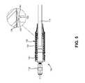
- yoke 102 of power cable splicing connector 100may include a central conductor 106 (also referred to as bus bar 106 ) and number of taps 108 - 1 to 108 - 3 (collectively “taps 108 ,” and generically “tap 108 ”).
- Central conductor 106may be formed of a suitably conductive material, such as copper, aluminum, or other conductive alloy.
- central conductor 106may include bus extensions 110 - 1 to 110 - 3 (collectively “bus extensions 110 ,” and generically “bus extension 110 ”) that project from respective taps 108 in yoke 102 .
- bus extensions 110collectively “bus extensions 110 ,” and generically “bus extension 110 ”
- central conductor 106may connect each of power cable assemblies 104 to each other power cable assembly 104 , such that power applied to one cable is transferred to each other cable.
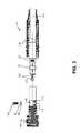
- tubular extension 140may be configured to fit within the inside diameter of insert 134 of cable receptacle 126 and over yoke spade portion 112 and crimp connector 116 without interference.
- tubular extension 140may have different wall thickness depending on the particular size and available clearances at the interface of crimp connector 116 and insert 134 .
- Tubular extension 140may include a metallic material, such as aluminum, or a plastic material, such as reinforced fiberglass.
- tubular extension 140may be made from the same material as central conductor 106 .
- Tubular extension 140may generally include a cylindrical shape or another tube-like cross-section (e.g., octagonal, hexagonal, etc.) to match the shape of bus extension 110 .
- Tubular extension 140may be secured to bus extension 110 by welding, by a threaded connection, or by another type of connection.
Landscapes
- Engineering & Computer Science (AREA)
- Manufacturing & Machinery (AREA)
- Details Of Connecting Devices For Male And Female Coupling (AREA)
- Connector Housings Or Holding Contact Members (AREA)
- Cable Accessories (AREA)
Abstract
Description
Claims (20)
Priority Applications (5)
| Application Number | Priority Date | Filing Date | Title |
|---|---|---|---|
| US13/903,049US8986034B2 (en) | 2012-07-12 | 2013-05-28 | Restraint and lock for electrical connector |
| CA2818427ACA2818427C (en) | 2012-07-12 | 2013-06-14 | Restraint and lock for electrical connector |
| EP13176192.6AEP2685563B1 (en) | 2012-07-12 | 2013-07-11 | Restraint and lock for electrical connector |
| MX2013008125AMX2013008125A (en) | 2012-07-12 | 2013-07-11 | Restraint and lock for electrical connector. |
| ES13176192.6TES2616580T3 (en) | 2012-07-12 | 2013-07-11 | Restriction or blocking element for electrical connector |
Applications Claiming Priority (2)
| Application Number | Priority Date | Filing Date | Title |
|---|---|---|---|
| US201261670828P | 2012-07-12 | 2012-07-12 | |
| US13/903,049US8986034B2 (en) | 2012-07-12 | 2013-05-28 | Restraint and lock for electrical connector |
Publications (2)
| Publication Number | Publication Date |
|---|---|
| US20140017923A1 US20140017923A1 (en) | 2014-01-16 |
| US8986034B2true US8986034B2 (en) | 2015-03-24 |
Family
ID=48771342
Family Applications (1)
| Application Number | Title | Priority Date | Filing Date |
|---|---|---|---|
| US13/903,049Active2033-08-25US8986034B2 (en) | 2012-07-12 | 2013-05-28 | Restraint and lock for electrical connector |
Country Status (5)
| Country | Link |
|---|---|
| US (1) | US8986034B2 (en) |
| EP (1) | EP2685563B1 (en) |
| CA (1) | CA2818427C (en) |
| ES (1) | ES2616580T3 (en) |
| MX (1) | MX2013008125A (en) |
Families Citing this family (2)
| Publication number | Priority date | Publication date | Assignee | Title |
|---|---|---|---|---|
| US10419567B2 (en)* | 2017-03-21 | 2019-09-17 | Elite Silicon Technology Inc. | Client terminal of audio device redirection system and audio device redirection method |
| EP4391263A1 (en)* | 2022-12-23 | 2024-06-26 | Nexans | Novel t-connector design for robust and versatile high voltage connections |
Citations (26)
| Publication number | Priority date | Publication date | Assignee | Title |
|---|---|---|---|---|
| US3689866A (en) | 1970-09-11 | 1972-09-05 | William Kelly | Heavy duty cable connector |
| US5277605A (en) | 1992-09-10 | 1994-01-11 | Cooper Power Systems, Inc. | Electrical connector |
| US5433622A (en) | 1994-07-07 | 1995-07-18 | Galambos; Louis G. | High voltage connector |
| EP0767523A2 (en) | 1995-10-02 | 1997-04-09 | Minnesota Mining And Manufacturing Company | Improved covering device |
| US5685730A (en) | 1996-03-15 | 1997-11-11 | Litton Precision Products International, Inc. | Power connector set with secondary lock |
| US6152770A (en) | 1999-03-26 | 2000-11-28 | Wang; Lien-Sheng | Water-proof socket adapter design |
| US6227908B1 (en) | 1996-07-26 | 2001-05-08 | Wolfram Aumeier | Electric connection |
| US6261131B1 (en) | 1999-03-01 | 2001-07-17 | J.S.T. Mfg. Co., Ltd | High-voltage connector |
| US6309231B1 (en) | 1999-09-02 | 2001-10-30 | Litton Precision Products International, Inc. | High current male and female power connector assembly |
| US6332785B1 (en) | 1997-06-30 | 2001-12-25 | Cooper Industries, Inc. | High voltage electrical connector with access cavity and inserts for use therewith |
| CA2286788C (en) | 1997-04-18 | 2002-07-30 | Yazaki Corporation | Connector with a terminal vibration preventing mechanism |
| US6485326B1 (en) | 2000-10-19 | 2002-11-26 | France/Scott Fetzer Company | High-voltage connection enclosure and method |
| US6729903B1 (en) | 2002-12-04 | 2004-05-04 | Maytag Corporation | Quick connect/disconnect electrical connector having an extended insulating tab |
| US20050095925A1 (en) | 2003-11-05 | 2005-05-05 | Luzzi Glenn J. | Barrier head bolt for use with the disconnectable joints and methods of using the same |
| US20080230359A1 (en) | 2007-03-22 | 2008-09-25 | Leccia Brad R | Electrically insulated conductor connection assemblies and associated method |
| US7491075B2 (en) | 2005-07-28 | 2009-02-17 | Cooper Technologies Company | Electrical connector |
| US7530843B1 (en) | 2008-03-19 | 2009-05-12 | Yazaki North America, Inc. | Sealed electrical terminal |
| US7695333B2 (en) | 2007-12-13 | 2010-04-13 | Cooper Technologies Company | Single pole cable connector |
| US7726998B2 (en)* | 2008-07-17 | 2010-06-01 | Thomas & Betts International, Inc. | Locking pin |
| US7892047B2 (en) | 2008-04-30 | 2011-02-22 | Cooper Technologies Company | Single pole cable connector with tamper resistant locking mechanism |
| WO2011061074A1 (en) | 2009-11-23 | 2011-05-26 | Tyco Electronics France Sas | Casing for an electrical connector |
| US8070509B2 (en) | 2009-09-16 | 2011-12-06 | Richard Manufacturing Company, a New Jersey Limited Partnership | Splice restraint and mating indicator |
| CA2752903A1 (en) | 2010-10-07 | 2012-04-07 | Thomas & Betts International, Inc. | Cam clamp for electrical connector |
| US8172624B2 (en) | 2008-12-05 | 2012-05-08 | Hubbell Incorporated | Wiring device assembly with contact stabilizing structure |
| US8616908B2 (en)* | 2010-03-03 | 2013-12-31 | Thomas & Betts International, Inc. | Electrical connector with a cap with a sacrificial conductor |
| US8882548B2 (en)* | 2010-10-07 | 2014-11-11 | Thomas & Betts International Llc | Cam clamp for electrical connector |
- 2013
- 2013-05-28USUS13/903,049patent/US8986034B2/enactiveActive
- 2013-06-14CACA2818427Apatent/CA2818427C/ennot_activeExpired - Fee Related
- 2013-07-11ESES13176192.6Tpatent/ES2616580T3/enactiveActive
- 2013-07-11EPEP13176192.6Apatent/EP2685563B1/enactiveActive
- 2013-07-11MXMX2013008125Apatent/MX2013008125A/enactiveIP Right Grant
Patent Citations (29)
| Publication number | Priority date | Publication date | Assignee | Title |
|---|---|---|---|---|
| US3689866A (en) | 1970-09-11 | 1972-09-05 | William Kelly | Heavy duty cable connector |
| US5277605A (en) | 1992-09-10 | 1994-01-11 | Cooper Power Systems, Inc. | Electrical connector |
| US5445533A (en) | 1992-09-10 | 1995-08-29 | Cooper Industries, Inc. | Electrical connector |
| US5525069A (en) | 1992-09-10 | 1996-06-11 | Cooper Industries, Inc. | Electrical Connector |
| US5433622A (en) | 1994-07-07 | 1995-07-18 | Galambos; Louis G. | High voltage connector |
| EP0767523A2 (en) | 1995-10-02 | 1997-04-09 | Minnesota Mining And Manufacturing Company | Improved covering device |
| US5685730A (en) | 1996-03-15 | 1997-11-11 | Litton Precision Products International, Inc. | Power connector set with secondary lock |
| US6227908B1 (en) | 1996-07-26 | 2001-05-08 | Wolfram Aumeier | Electric connection |
| CA2286788C (en) | 1997-04-18 | 2002-07-30 | Yazaki Corporation | Connector with a terminal vibration preventing mechanism |
| US6332785B1 (en) | 1997-06-30 | 2001-12-25 | Cooper Industries, Inc. | High voltage electrical connector with access cavity and inserts for use therewith |
| US6261131B1 (en) | 1999-03-01 | 2001-07-17 | J.S.T. Mfg. Co., Ltd | High-voltage connector |
| US6152770A (en) | 1999-03-26 | 2000-11-28 | Wang; Lien-Sheng | Water-proof socket adapter design |
| US6309231B1 (en) | 1999-09-02 | 2001-10-30 | Litton Precision Products International, Inc. | High current male and female power connector assembly |
| US6485326B1 (en) | 2000-10-19 | 2002-11-26 | France/Scott Fetzer Company | High-voltage connection enclosure and method |
| US6729903B1 (en) | 2002-12-04 | 2004-05-04 | Maytag Corporation | Quick connect/disconnect electrical connector having an extended insulating tab |
| US20050095925A1 (en) | 2003-11-05 | 2005-05-05 | Luzzi Glenn J. | Barrier head bolt for use with the disconnectable joints and methods of using the same |
| US7870668B2 (en) | 2005-07-28 | 2011-01-18 | Cooper Technologies Company | Method for connecting an electrical connector to a cable connector |
| US7491075B2 (en) | 2005-07-28 | 2009-02-17 | Cooper Technologies Company | Electrical connector |
| US20080230359A1 (en) | 2007-03-22 | 2008-09-25 | Leccia Brad R | Electrically insulated conductor connection assemblies and associated method |
| US7695333B2 (en) | 2007-12-13 | 2010-04-13 | Cooper Technologies Company | Single pole cable connector |
| US7530843B1 (en) | 2008-03-19 | 2009-05-12 | Yazaki North America, Inc. | Sealed electrical terminal |
| US7892047B2 (en) | 2008-04-30 | 2011-02-22 | Cooper Technologies Company | Single pole cable connector with tamper resistant locking mechanism |
| US7726998B2 (en)* | 2008-07-17 | 2010-06-01 | Thomas & Betts International, Inc. | Locking pin |
| US8172624B2 (en) | 2008-12-05 | 2012-05-08 | Hubbell Incorporated | Wiring device assembly with contact stabilizing structure |
| US8070509B2 (en) | 2009-09-16 | 2011-12-06 | Richard Manufacturing Company, a New Jersey Limited Partnership | Splice restraint and mating indicator |
| WO2011061074A1 (en) | 2009-11-23 | 2011-05-26 | Tyco Electronics France Sas | Casing for an electrical connector |
| US8616908B2 (en)* | 2010-03-03 | 2013-12-31 | Thomas & Betts International, Inc. | Electrical connector with a cap with a sacrificial conductor |
| CA2752903A1 (en) | 2010-10-07 | 2012-04-07 | Thomas & Betts International, Inc. | Cam clamp for electrical connector |
| US8882548B2 (en)* | 2010-10-07 | 2014-11-11 | Thomas & Betts International Llc | Cam clamp for electrical connector |
Non-Patent Citations (1)
| Title |
|---|
| Extended European search report dated Jan. 20, 2015 for corresponding European Application No. 13176192. |
Also Published As
| Publication number | Publication date |
|---|---|
| MX2013008125A (en) | 2014-01-17 |
| CA2818427A1 (en) | 2014-01-12 |
| EP2685563B1 (en) | 2016-12-28 |
| CA2818427C (en) | 2016-07-05 |
| EP2685563A3 (en) | 2015-02-18 |
| ES2616580T3 (en) | 2017-06-13 |
| EP2685563A2 (en) | 2014-01-15 |
| US20140017923A1 (en) | 2014-01-16 |
Similar Documents
| Publication | Publication Date | Title |
|---|---|---|
| US9954315B2 (en) | Grounding link for electrical connector mechanism | |
| EP2688153B1 (en) | Electrical connector having grounding mechanism | |
| US8979590B2 (en) | Cable gland for electrical cable fitting | |
| US8172596B2 (en) | Electrical connector with sacrificial appendage | |
| US9472868B2 (en) | Permanent ground point for splicing connectors | |
| US20110256746A1 (en) | Electrical connector having alignment mechanism | |
| EP3062399B1 (en) | Multi-piece jacket for separable connectors | |
| US8986034B2 (en) | Restraint and lock for electrical connector | |
| HK1223456B (en) | Electrical connector assembly comprising a grounding link and corresponding method of connection | |
| HK1226870B (en) | Multi-piece jacket for separable connectors | |
| HK1226870A1 (en) | Multi-piece jacket for separable connectors |
Legal Events
| Date | Code | Title | Description |
|---|---|---|---|
| AS | Assignment | Owner name:THOMAS & BETTS INTERNATIONAL, INC., DELAWARE Free format text:ASSIGNMENT OF ASSIGNORS INTEREST;ASSIGNOR:SIEBENS, LARRY N.;REEL/FRAME:030492/0122 Effective date:20130524 | |
| FEPP | Fee payment procedure | Free format text:PAYOR NUMBER ASSIGNED (ORIGINAL EVENT CODE: ASPN); ENTITY STATUS OF PATENT OWNER: LARGE ENTITY | |
| STCF | Information on status: patent grant | Free format text:PATENTED CASE | |
| CC | Certificate of correction | ||
| AS | Assignment | Owner name:THOMAS & BETTS INTERNATIONAL LLC, DELAWARE Free format text:CHANGE OF NAME;ASSIGNOR:THOMAS & BETTS INTERNATIONAL, INC.;REEL/FRAME:040229/0179 Effective date:20130820 | |
| MAFP | Maintenance fee payment | Free format text:PAYMENT OF MAINTENANCE FEE, 4TH YEAR, LARGE ENTITY (ORIGINAL EVENT CODE: M1551); ENTITY STATUS OF PATENT OWNER: LARGE ENTITY Year of fee payment:4 | |
| MAFP | Maintenance fee payment | Free format text:PAYMENT OF MAINTENANCE FEE, 8TH YEAR, LARGE ENTITY (ORIGINAL EVENT CODE: M1552); ENTITY STATUS OF PATENT OWNER: LARGE ENTITY Year of fee payment:8 |