US8985544B1 - Anti-theft device for functional display of handheld devices - Google Patents
Anti-theft device for functional display of handheld devicesDownload PDFInfo
- Publication number
- US8985544B1 US8985544B1US12/069,479US6947908AUS8985544B1US 8985544 B1US8985544 B1US 8985544B1US 6947908 AUS6947908 AUS 6947908AUS 8985544 B1US8985544 B1US 8985544B1
- Authority
- US
- United States
- Prior art keywords
- leveling
- arm
- leveling plate
- screw
- security device
- Prior art date
- Legal status (The legal status is an assumption and is not a legal conclusion. Google has not performed a legal analysis and makes no representation as to the accuracy of the status listed.)
- Active
Links
- 230000014759maintenance of locationEffects0.000claimsdescription10
- 238000007689inspectionMethods0.000description5
- 230000003028elevating effectEffects0.000description3
- 230000000295complement effectEffects0.000description2
- 230000001419dependent effectEffects0.000description2
- 238000012986modificationMethods0.000description2
- 230000004048modificationEffects0.000description2
- 230000000717retained effectEffects0.000description2
- 239000000853adhesiveSubstances0.000description1
- 230000001070adhesive effectEffects0.000description1
- 230000000903blocking effectEffects0.000description1
- 230000013011matingEffects0.000description1
- 238000000034methodMethods0.000description1
- 238000009877renderingMethods0.000description1
- 239000003381stabilizerSubstances0.000description1
Images


Classifications
- F—MECHANICAL ENGINEERING; LIGHTING; HEATING; WEAPONS; BLASTING
- F16—ENGINEERING ELEMENTS AND UNITS; GENERAL MEASURES FOR PRODUCING AND MAINTAINING EFFECTIVE FUNCTIONING OF MACHINES OR INSTALLATIONS; THERMAL INSULATION IN GENERAL
- F16M—FRAMES, CASINGS OR BEDS OF ENGINES, MACHINES OR APPARATUS, NOT SPECIFIC TO ENGINES, MACHINES OR APPARATUS PROVIDED FOR ELSEWHERE; STANDS; SUPPORTS
- F16M13/00—Other supports for positioning apparatus or articles; Means for steadying hand-held apparatus or articles
- A—HUMAN NECESSITIES
- A47—FURNITURE; DOMESTIC ARTICLES OR APPLIANCES; COFFEE MILLS; SPICE MILLS; SUCTION CLEANERS IN GENERAL
- A47F—SPECIAL FURNITURE, FITTINGS, OR ACCESSORIES FOR SHOPS, STOREHOUSES, BARS, RESTAURANTS OR THE LIKE; PAYING COUNTERS
- A47F7/00—Show stands, hangers, or shelves, adapted for particular articles or materials
- A47F7/02—Show stands, hangers, or shelves, adapted for particular articles or materials for jewellery, dentures, watches, eye-glasses, lenses, or the like
- A47F7/024—Show stands, hangers, or shelves, adapted for particular articles or materials for jewellery, dentures, watches, eye-glasses, lenses, or the like with provisions for preventing unauthorised removal
- F—MECHANICAL ENGINEERING; LIGHTING; HEATING; WEAPONS; BLASTING
- F16—ENGINEERING ELEMENTS AND UNITS; GENERAL MEASURES FOR PRODUCING AND MAINTAINING EFFECTIVE FUNCTIONING OF MACHINES OR INSTALLATIONS; THERMAL INSULATION IN GENERAL
- F16M—FRAMES, CASINGS OR BEDS OF ENGINES, MACHINES OR APPARATUS, NOT SPECIFIC TO ENGINES, MACHINES OR APPARATUS PROVIDED FOR ELSEWHERE; STANDS; SUPPORTS
- F16M11/00—Stands or trestles as supports for apparatus or articles placed thereon ; Stands for scientific apparatus such as gravitational force meters
- F16M11/02—Heads
- F16M11/04—Means for attachment of apparatus; Means allowing adjustment of the apparatus relatively to the stand
- F16M11/041—Allowing quick release of the apparatus
Definitions
- the inventionrelates to security devices for allowing display of handheld products and, more particularly, to a universal clamping apparatus to prevent theft of handheld electronic devices without hindering customer inspection thereof.
- Retailerssell light weight wireless phones, handheld computers, radios, scanners, pagers, GPS systems, multimeters, cameras, music players, power tools, calculators, and similar electronic devices to the public in a range of shapes and sizes, with a range of functionality. Encouraging customers to pick up, hold, examine, and use the features of the devices is a valuable marketing technique employed by retailers. To decrease the risk of theft associated with this marketing strategy, retailers often further employ security measures to physically retain the electronic device within a short distance from its display location. Current security devices that allow customers to manipulate displayed electronic devices are often designed for specific types, brands, sizes, or shapes. Current security devices that claim to fit handheld electronics universally, in fact, do not. These security devices are bulky and obtrusive, blocking full customer inspection of features.
- U.S. Pat. No. 6,659,382 issued Dec. 9, 2003 to Ryczekdiscloses a security device by which cell phones or similar handheld electronic devices can be fastened within a clamp and tethered to a display location.
- the clampconsists of an upper jaw and a lower jaw.
- a flange with a holeprotrudes perpendicularly off the dorsal side of each jaw for a screw to pass through and tighten the jaws together.
- Up to six sides of an electronic deviceare thereby fastened within the upper and lower jaws.
- the security deviceis not adjustable to fit varying sizes and types of electronic devices. Multiple models must be designed for specific types, sizes, or shapes of electronic handheld devices. Additionally, clamping on up to six sides of electronic devices, including but not limited to slide and flip-top wireless phones, inhibits customer inspection of some features and functionality.
- U.S. Pat. No. 5,246,183 issued on Sep. 21, 1993 to Leydendiscloses an anti-theft device for use with television remote controls in locations such as hotels and motels.
- a flat disk at the end of a tetherretracts to a base.
- Adhesiveattaches the flat disk to a flat surface of the remote control.
- the attaching diskis not intended to be used with various types of items, and it is not intended for repeat attachment and detachment.
- U.S. Pat. No. 6,002,921 issued Dec. 14, 1999 to Pfahlert et al.discloses a lockable cradle for holding a radiotelephone.
- a radio signalis used to lock and unlock the arms that clamp around the sides of a phone.
- This anti-theft deviceis not intended to display or use the radiotelephone and all its features while locked in the cradle. It has a mating system to attach to a base, rendering a locked item unable to be held and manipulated while locked to a location.
- an anti-theft devicefor gripping handheld electronics and fastening them to a display location.
- a drive gearis powered manually by a special key, driving at least one axle gear. As the axle gears turn, the screwing motion contracts and expands legs to tighten and loosen their grip on the handheld devices.
- the devicemay attach to a tether or other similar retracting and/or positioning system.
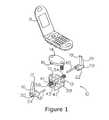
- FIG. 1is an exploded perspective view of the anti-theft device in accordance with the invention, with cell phone shown in proper alignment for attachment thereto;
- FIG. 2 ais a top view of the main housing body, absent the top plate;
- FIG. 2 bis a top view of the top plate
- FIG. 2 cis a side view of the top plate
- FIG. 3 ais a front view of the anti-theft device
- FIG. 3 bis a front view of the device, with cell phone attached therein;
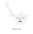
- FIG. 4 ais a side view of the device
- FIG. 4 bis a side view of the device, with a cell phone attached therein;
- FIG. 5is a bottom view of the device.
- an anti-theft apparatusfor gripping mobile phones, cameras, computers, radios, scanners, pagers, GPS systems, and similar electronic devices to allow secure marketing display of the handheld products.
- the gripping devicehas a body with an upper surface, a first arm with a distal end and a second arm having a distal end. Also provided is a device for extending and retracting the first and second arms along an X-axis relative to respective first and second sides of the body.
- a leveling plateis movably connected to the body between the first and second arms. Also, the leveling plate can move along a Z-axis relative to the upper surface of the body.
- the inventionis shown to include a retention device 10 for securely holding a cell phone 8 .
- retention device 10comprises a moveable shim plate 14 and first moveable arm 16 and a second moveable arm 18 .
- Shim plate 14moves vertically in alignment with the Z axis; first moveable arm 16 and second moveable arm 18 move horizontally in alignment with the X axis.
- first moveable arm 16 and second moveable arm 18 along the X axisis controlled by the rotation of draw pin 28 , which retains two threaded ends 34 , 36 , each of which is machined with a thread pattern that is counter rotational to the other.
- threaded hole 24 in arm base 20 and threaded hole 26 in arm base 22are each machined with a thread pattern that is counter rotational to the other.
- Threaded end 36is complementary to threaded hold 24
- threaded end 34is complementary to threaded hole 26 . Therefore, it is critical to function that threaded end 36 is inserted into threaded hole 24 , while threaded end 24 is inserted into threaded hole 26 .
- a draw pin 28extends through the center of housing body 12 via hole 29 .
- Draw pin 28is held in place by lock washer 30 , which is attached at opposing end portions of draw pin 28 and so positioned to abut the side walls of housing body 12 .
- draw pin 28is controlled by inserting a suitable tool (not shown) into hex key hole 32 at the tip of threaded end 34 of draw pin 28 .
- a security pin 33Disposed with hex key hole 32 is a security pin 33 ( FIGS. 4 a , 5 ) that can be turned by the suitable tool.
- draw pin 28is simultaneously rotated in a clockwise direction. This screws the opposing threaded ends 34 and 36 into threaded holes 26 and 24 , respectively, which serves to draw first moveable arm 16 and second moveable arm 18 towards one another, and towards the center of housing body 12 .
- first moveable arm 16 and second moveable arm 18are drawn away from each other, and away from the center of housing body 12 .
- first moveable arm 16 and second moveable arm 18as well as optional retention hooks 17 and 19 , can be infinitely adjusted to clamp onto and securely hold the sides and top edges of cell phone 8 .
- first moveable arm 16 and second moveable arm 18are arbitrarily dependent upon the electronic device that is to be retained, the range for the embodiment shown herein is approximately 3.125′′ at the widest adjustment and approximately 0.702′′ at the narrowest adjustment.
- locator pins 38 and 40are fixedly attached to arm bases 20 and 22 , respectively.
- Locator pin 38extends through locator hole 39 ;
- locator pin 40extends through locator hole 41 .
- Each pin 38 , 40is parallel to the axis of draw pin 28 , and in the same plane thereof. As draw pin 28 is rotated, thereby moving first moveable arm 16 and second moveable arm 18 into a wider or narrower adjustment state, locater pins 38 and 40 slide correspondingly through locator holes 39 and 41 .
- locator pins 38 and 40function as stabilizer means to prevent arm bases 20 and 22 from deviating from their fixed alignment, which in turn maintains the perpendicular alignment of first moveable arm 16 and second moveable arm 18 as they move through various states of adjustment as described above.
- each of shim pins 15retains hex key hole, retains a corresponding hex key hole 54 .
- the corresponding shim pin 15rotates clockwise or counter-clockwise.
- shim pins 15when shim pins 15 are rotated clockwise into threaded holes 13 , shim pins 15 rise along the threads of threaded holes 13 , thereby elevating the end of pins 15 that are fixedly attached to shim plate 14 . In this manner, shim plate 14 may be elevated in a gradual and controlled manner. Conversely, when threaded shim pins 15 are rotated in a counter-clockwise direction, shim plate 14 is lowered along the threads of threaded holes 13 in a likewise gradual and controlled manner. While the elevating distance of shim plate 14 is arbitrarily dependent upon the size of the electronic device retained, the elevating distance for the embodiment described herein is approximately 0.65 inches.
- each end of shim plate 14may be raised or lowered, by alternate turn in graduated increments, thereby raising or lowering plate 14 in a level manner.
- Thisallows shim plate 14 to function substantially as a screw type jack to elevate cell phone 8 and press it securely against optional retention hooks 17 and 19 , thereby holding cell phone 8 fixedly between shim plate 14 and retention hooks 17 , 19 .
- attachment flanges 42 and 43extend from the bottom portion of housing body 12 .
- Attachment flange 42retains hole 46 ;
- attachment flange 43retains threaded hole 48 .
- Threaded attachment pin 44inserts freely through hole 46 and thence to threaded hole 48 .
- This security featureis enhanced by the fact that the head of attachment pin 44 retains a hex key hole 50 , thereby requiring a tool or key of certain size for removal, a specialty tool rarely carried by the average consumer, or even the average consumer inclined to shoplift goods from a retail establishment. Disposed with hex key hole 50 can be security pin 52 .
- retention device 10is adjustable to accommodate the width and height of virtually any cell phone in use today, and to securely grip and hold virtually any cell phone in a manner that allows full use and inspection of all relevant features of the cell phone by consumers at a retail location where the cell phone is displayed for sale.
Landscapes
- Engineering & Computer Science (AREA)
- General Engineering & Computer Science (AREA)
- Mechanical Engineering (AREA)
- Burglar Alarm Systems (AREA)
- Telephone Set Structure (AREA)
Abstract
Description
Claims (14)
Priority Applications (1)
| Application Number | Priority Date | Filing Date | Title |
|---|---|---|---|
| US12/069,479US8985544B1 (en) | 2006-08-29 | 2008-02-11 | Anti-theft device for functional display of handheld devices |
Applications Claiming Priority (2)
| Application Number | Priority Date | Filing Date | Title |
|---|---|---|---|
| US48148606A | 2006-08-29 | 2006-08-29 | |
| US12/069,479US8985544B1 (en) | 2006-08-29 | 2008-02-11 | Anti-theft device for functional display of handheld devices |
Related Parent Applications (1)
| Application Number | Title | Priority Date | Filing Date |
|---|---|---|---|
| US48148606AContinuation-In-Part | 2006-08-29 | 2006-08-29 |
Publications (1)
| Publication Number | Publication Date |
|---|---|
| US8985544B1true US8985544B1 (en) | 2015-03-24 |
Family
ID=52683202
Family Applications (1)
| Application Number | Title | Priority Date | Filing Date |
|---|---|---|---|
| US12/069,479ActiveUS8985544B1 (en) | 2006-08-29 | 2008-02-11 | Anti-theft device for functional display of handheld devices |
Country Status (1)
| Country | Link |
|---|---|
| US (1) | US8985544B1 (en) |
Cited By (24)
| Publication number | Priority date | Publication date | Assignee | Title |
|---|---|---|---|---|
| US20150089675A1 (en)* | 2012-05-09 | 2015-03-26 | Scorpion Secruity Products, Inc. | Security device for functional display, security, and charging of handheld electronic devices |
| US20150282345A1 (en)* | 2014-03-31 | 2015-10-01 | Iottie, Inc | Mounting System For Portable Device |
| US20180058107A1 (en)* | 2015-03-02 | 2018-03-01 | Rtf Europe Limited | Security device |
| US9936823B2 (en) | 2012-11-23 | 2018-04-10 | Compucage International Inc. | Security system for displaying objects |
| US9972178B2 (en) | 2014-01-23 | 2018-05-15 | Invue Security Products Inc. | Systems and methods for security sensing in a power cable for an article of merchandise |
| US20180279805A1 (en)* | 2012-11-23 | 2018-10-04 | Compucage International Inc. | Security system for displaying objects |
| US10098481B2 (en)* | 2014-08-27 | 2018-10-16 | Invue Security Products Inc. | Systems and methods for locking a sensor to a base |
| US10165873B2 (en) | 2015-08-17 | 2019-01-01 | Scorpion Security Products, Inc. | Security device for functional display and security of handheld electronic devices |
| US10448759B1 (en) | 2018-06-12 | 2019-10-22 | ONQ Solutions, Inc. | Adjustable size apparatuses that secure portable electronic devices to display tables |
| US10920922B2 (en) | 2019-07-18 | 2021-02-16 | ONQ Solutions, Inc. | Quickly customizable apparatuses that secure portable electronic devices to display tables and other display surfaces |
| US11015626B2 (en) | 2018-10-08 | 2021-05-25 | Se-Kure Controls, Inc. | Support assembly for displaying a portable article |
| US11122917B2 (en) | 2019-08-30 | 2021-09-21 | ONQ Solutions, Inc. | Adjustable apparatuses that secure laptop computers to display tables |
| USD934229S1 (en) | 2020-02-24 | 2021-10-26 | ONQ Solutions, Inc. | Mount for securing a portable device |
| CN113639175A (en)* | 2021-01-14 | 2021-11-12 | 深圳市优至胜科技有限公司 | Quick mount, quick release assembly and camera |
| US11178983B1 (en)* | 2020-01-14 | 2021-11-23 | Vanguard Products Group, Inc. | Modular security cradle for safeguarding an article of merchandise against theft |
| USD942440S1 (en) | 2020-02-24 | 2022-02-01 | ONQ Solutions, Inc. | Mount for securing a portable device |
| US11346136B2 (en)* | 2018-04-11 | 2022-05-31 | Scorpion Security Products, Inc. | Security apparatus |
| US11412865B2 (en)* | 2020-04-07 | 2022-08-16 | ONQ Solutions, Inc. | Apparatuses that secure wearables to display tables and other display surfaces |
| US11432663B2 (en) | 2019-07-18 | 2022-09-06 | ONQ Solutions, Inc. | Adjustable apparatuses that secure tablet computing devices and keyboards to display tables |
| US11680428B2 (en) | 2021-06-29 | 2023-06-20 | ONQ Solutions, Inc. | Adjustable apparatuses to secure electronic devices to display tables |
| US11739568B2 (en) | 2021-07-26 | 2023-08-29 | ONQ Solutions, Inc. | Apparatuses that secure laptops to display surfaces |
| WO2024035860A1 (en)* | 2022-08-12 | 2024-02-15 | Invue Security Products Inc. | Bracket for merchandise security system |
| US12276373B1 (en) | 2023-10-20 | 2025-04-15 | ONQ Solutions, Inc. | Apparatus to secure one or more electronic devices to a display table |
| US12385291B2 (en) | 2023-03-28 | 2025-08-12 | ONQ Solutions, Inc. | Adjustable security bracket for laptop computers |
Citations (46)
| Publication number | Priority date | Publication date | Assignee | Title |
|---|---|---|---|---|
| US19622A (en)* | 1858-03-16 | Petefis | ||
| US242959A (en)* | 1881-06-14 | Work-holding clamp | ||
| US297981A (en)* | 1884-05-06 | Ring and watch-case attachment for engraving-machines | ||
| US339072A (en)* | 1886-03-30 | Clamp | ||
| US351550A (en)* | 1886-10-26 | elger | ||
| US528557A (en)* | 1894-11-06 | Clamping device for machine-tools | ||
| US685078A (en)* | 1901-01-22 | 1901-10-22 | Gustav Willringhaus | Tool-maker's clamp. |
| US762070A (en)* | 1903-08-17 | 1904-06-07 | Clarence C Longard | Vise. |
| US774810A (en)* | 1902-03-31 | 1904-11-15 | George M Willis | Rail-bond compressor. |
| US887103A (en)* | 1907-09-28 | 1908-05-12 | John H Lane | Woodworking-clamp. |
| US1075384A (en)* | 1913-05-13 | 1913-10-14 | Emil K F Seidel | Woodworking-clamp. |
| US1402621A (en)* | 1919-10-06 | 1922-01-03 | Knittel Carl | Three-way clamp |
| US1586314A (en)* | 1924-04-24 | 1926-05-25 | Kiefer Michael | Clamp |
| US1709385A (en)* | 1927-05-17 | 1929-04-16 | Carl I Young | Cabinetmaker's clamp |
| US2094225A (en)* | 1935-07-06 | 1937-09-28 | Jess L Tuttle | Tool |
| US2114227A (en)* | 1936-04-23 | 1938-04-12 | Kriss Joseph | Clamp |
| US2225273A (en)* | 1939-01-13 | 1940-12-17 | Phillips Petroleum Co | Rotating adjustable tilting table chuck |
| US2424871A (en)* | 1944-04-18 | 1947-07-29 | Keystone Mfg Co | Tool for flaring tubing |
| US2552094A (en)* | 1947-12-18 | 1951-05-08 | Wesley M Hamon | Three jaw vise |
| US2610661A (en)* | 1947-02-06 | 1952-09-16 | Romine James Earl | C-clamp with right-angularly related clamping screws |
| US2716362A (en)* | 1954-11-09 | 1955-08-30 | Stanley W Novak | Cable-splicing vise |
| US3741517A (en)* | 1971-02-09 | 1973-06-26 | Texaco Inc | Subterranean clamping mechanism for submarine wells |
| US3855825A (en)* | 1973-03-05 | 1974-12-24 | Stanford E | Bicycle lock |
| US4083547A (en)* | 1977-07-01 | 1978-04-11 | Gurley Grey M | Vise |
| US4234176A (en)* | 1979-08-17 | 1980-11-18 | Goff Otis W | Quick release clamp |
| US5052199A (en)* | 1990-11-30 | 1991-10-01 | Derman Jay S | Clamp locking device for PC's and the like |
| US5246183A (en) | 1991-04-04 | 1993-09-21 | Se-Kure Controls | Security device for a hand-held remote control |
| US5463688A (en)* | 1994-05-19 | 1995-10-31 | Motorola | Telephone mounting receptacle having opposed retractable latch members |
| US5555302A (en) | 1995-07-18 | 1996-09-10 | Wang; Chin-Yang | Mobile telephone holder |
| USRE35677E (en)* | 1991-07-01 | 1997-12-02 | Lucasey Manufacturing Company | Adjustable mounting and security device for appliances |
| US5697601A (en)* | 1996-08-20 | 1997-12-16 | Adjustable Clamp | Two-way dual action clamp |
| US5825874A (en)* | 1996-08-09 | 1998-10-20 | Nokia Mobile Phones Limited | Mobile telephone holder |
| US5848562A (en)* | 1996-10-28 | 1998-12-15 | Somma Tool Company, Inc. | Side operated clamp for resharpenable insert tool holder |
| US5863033A (en)* | 1997-02-01 | 1999-01-26 | Bradford; John-Paul | Dual-action clamp |
| US5893553A (en)* | 1997-10-17 | 1999-04-13 | Pinkous; Stephen L. | Portable C-clamp with non-rotatable clamping pad means |
| US5903645A (en) | 1996-10-23 | 1999-05-11 | Tsay; Wen-Feng | Clamping device for mobile phones |
| US6002921A (en) | 1997-11-17 | 1999-12-14 | Ericsson Inc. | Lockable radiotelephone cradle |
| US6000686A (en)* | 1998-03-16 | 1999-12-14 | Yates; W. Shuford | Locking three-way clamp |
| US6176479B1 (en)* | 2000-01-07 | 2001-01-23 | Charles A. Hicklin | Clamping device |
| US6199804B1 (en)* | 1998-08-07 | 2001-03-13 | Nicholas Donofrio, Jr. | Display device for sports memorablilia |
| US6220589B1 (en)* | 2000-01-05 | 2001-04-24 | Adjustable Clamp Company | Dual action clamp |
| US6237375B1 (en)* | 1999-12-10 | 2001-05-29 | William E. Wymer | Lap top lock |
| US6659382B2 (en) | 2001-07-10 | 2003-12-09 | Vira Manufacturing, Inc. | Security device for display of hand held items |
| US6848662B2 (en)* | 2002-01-24 | 2005-02-01 | Zih Corp. | Secure latching system |
| US7111764B2 (en)* | 2003-11-11 | 2006-09-26 | Nordman Corporation Of Nc | Clamp assembly for securing a ladder to a vehicle rack |
| US7197962B2 (en)* | 2003-11-12 | 2007-04-03 | Steven Andrew Williams | Light bulb installation and removal device |
- 2008
- 2008-02-11USUS12/069,479patent/US8985544B1/enactiveActive
Patent Citations (48)
| Publication number | Priority date | Publication date | Assignee | Title |
|---|---|---|---|---|
| US19622A (en)* | 1858-03-16 | Petefis | ||
| US242959A (en)* | 1881-06-14 | Work-holding clamp | ||
| US297981A (en)* | 1884-05-06 | Ring and watch-case attachment for engraving-machines | ||
| US339072A (en)* | 1886-03-30 | Clamp | ||
| US351550A (en)* | 1886-10-26 | elger | ||
| US528557A (en)* | 1894-11-06 | Clamping device for machine-tools | ||
| US685078A (en)* | 1901-01-22 | 1901-10-22 | Gustav Willringhaus | Tool-maker's clamp. |
| US774810A (en)* | 1902-03-31 | 1904-11-15 | George M Willis | Rail-bond compressor. |
| US762070A (en)* | 1903-08-17 | 1904-06-07 | Clarence C Longard | Vise. |
| US887103A (en)* | 1907-09-28 | 1908-05-12 | John H Lane | Woodworking-clamp. |
| US1075384A (en)* | 1913-05-13 | 1913-10-14 | Emil K F Seidel | Woodworking-clamp. |
| US1402621A (en)* | 1919-10-06 | 1922-01-03 | Knittel Carl | Three-way clamp |
| US1586314A (en)* | 1924-04-24 | 1926-05-25 | Kiefer Michael | Clamp |
| US1709385A (en)* | 1927-05-17 | 1929-04-16 | Carl I Young | Cabinetmaker's clamp |
| US2094225A (en)* | 1935-07-06 | 1937-09-28 | Jess L Tuttle | Tool |
| US2114227A (en)* | 1936-04-23 | 1938-04-12 | Kriss Joseph | Clamp |
| US2225273A (en)* | 1939-01-13 | 1940-12-17 | Phillips Petroleum Co | Rotating adjustable tilting table chuck |
| US2424871A (en)* | 1944-04-18 | 1947-07-29 | Keystone Mfg Co | Tool for flaring tubing |
| US2610661A (en)* | 1947-02-06 | 1952-09-16 | Romine James Earl | C-clamp with right-angularly related clamping screws |
| US2552094A (en)* | 1947-12-18 | 1951-05-08 | Wesley M Hamon | Three jaw vise |
| US2716362A (en)* | 1954-11-09 | 1955-08-30 | Stanley W Novak | Cable-splicing vise |
| US3741517A (en)* | 1971-02-09 | 1973-06-26 | Texaco Inc | Subterranean clamping mechanism for submarine wells |
| US3855825A (en)* | 1973-03-05 | 1974-12-24 | Stanford E | Bicycle lock |
| US4083547A (en)* | 1977-07-01 | 1978-04-11 | Gurley Grey M | Vise |
| US4234176A (en)* | 1979-08-17 | 1980-11-18 | Goff Otis W | Quick release clamp |
| US5052199A (en)* | 1990-11-30 | 1991-10-01 | Derman Jay S | Clamp locking device for PC's and the like |
| US5246183A (en) | 1991-04-04 | 1993-09-21 | Se-Kure Controls | Security device for a hand-held remote control |
| US5246183B1 (en) | 1991-04-04 | 1997-06-03 | Sekure Controls Inc | Security device for a hand-held remote control |
| USRE35677E (en)* | 1991-07-01 | 1997-12-02 | Lucasey Manufacturing Company | Adjustable mounting and security device for appliances |
| US5463688A (en)* | 1994-05-19 | 1995-10-31 | Motorola | Telephone mounting receptacle having opposed retractable latch members |
| US5555302A (en) | 1995-07-18 | 1996-09-10 | Wang; Chin-Yang | Mobile telephone holder |
| US5825874A (en)* | 1996-08-09 | 1998-10-20 | Nokia Mobile Phones Limited | Mobile telephone holder |
| US5697601A (en)* | 1996-08-20 | 1997-12-16 | Adjustable Clamp | Two-way dual action clamp |
| US5903645A (en) | 1996-10-23 | 1999-05-11 | Tsay; Wen-Feng | Clamping device for mobile phones |
| US5848562A (en)* | 1996-10-28 | 1998-12-15 | Somma Tool Company, Inc. | Side operated clamp for resharpenable insert tool holder |
| US6161823A (en)* | 1997-02-01 | 2000-12-19 | Bradford; John-Paul | Apparatus for adapting a clamp |
| US5863033A (en)* | 1997-02-01 | 1999-01-26 | Bradford; John-Paul | Dual-action clamp |
| US5893553A (en)* | 1997-10-17 | 1999-04-13 | Pinkous; Stephen L. | Portable C-clamp with non-rotatable clamping pad means |
| US6002921A (en) | 1997-11-17 | 1999-12-14 | Ericsson Inc. | Lockable radiotelephone cradle |
| US6000686A (en)* | 1998-03-16 | 1999-12-14 | Yates; W. Shuford | Locking three-way clamp |
| US6199804B1 (en)* | 1998-08-07 | 2001-03-13 | Nicholas Donofrio, Jr. | Display device for sports memorablilia |
| US6237375B1 (en)* | 1999-12-10 | 2001-05-29 | William E. Wymer | Lap top lock |
| US6220589B1 (en)* | 2000-01-05 | 2001-04-24 | Adjustable Clamp Company | Dual action clamp |
| US6176479B1 (en)* | 2000-01-07 | 2001-01-23 | Charles A. Hicklin | Clamping device |
| US6659382B2 (en) | 2001-07-10 | 2003-12-09 | Vira Manufacturing, Inc. | Security device for display of hand held items |
| US6848662B2 (en)* | 2002-01-24 | 2005-02-01 | Zih Corp. | Secure latching system |
| US7111764B2 (en)* | 2003-11-11 | 2006-09-26 | Nordman Corporation Of Nc | Clamp assembly for securing a ladder to a vehicle rack |
| US7197962B2 (en)* | 2003-11-12 | 2007-04-03 | Steven Andrew Williams | Light bulb installation and removal device |
Cited By (35)
| Publication number | Priority date | Publication date | Assignee | Title |
|---|---|---|---|---|
| US9298219B2 (en)* | 2012-05-09 | 2016-03-29 | Scorpion Security Products, Inc. | Security device for functional display, security, and charging of handheld electronic devices |
| US20150089675A1 (en)* | 2012-05-09 | 2015-03-26 | Scorpion Secruity Products, Inc. | Security device for functional display, security, and charging of handheld electronic devices |
| US9936823B2 (en) | 2012-11-23 | 2018-04-10 | Compucage International Inc. | Security system for displaying objects |
| US20180279805A1 (en)* | 2012-11-23 | 2018-10-04 | Compucage International Inc. | Security system for displaying objects |
| US10624471B2 (en)* | 2012-11-23 | 2020-04-21 | Compucage International Inc. | Security system for displaying objects |
| US10223883B2 (en) | 2014-01-23 | 2019-03-05 | Invue Security Products Inc. | Systems and methods for security sensing in a power cable for an article of merchandise |
| US9972178B2 (en) | 2014-01-23 | 2018-05-15 | Invue Security Products Inc. | Systems and methods for security sensing in a power cable for an article of merchandise |
| US20150282345A1 (en)* | 2014-03-31 | 2015-10-01 | Iottie, Inc | Mounting System For Portable Device |
| US9651069B2 (en)* | 2014-03-31 | 2017-05-16 | Iottie, Inc. | Mounting system for portable device |
| US11399640B2 (en) | 2014-08-27 | 2022-08-02 | Invue Security Products Inc. | Systems and methods for locking a sensor to a base |
| US10098481B2 (en)* | 2014-08-27 | 2018-10-16 | Invue Security Products Inc. | Systems and methods for locking a sensor to a base |
| US12295509B2 (en) | 2014-08-27 | 2025-05-13 | Invue Security Products Inc. | Systems and methods for locking a sensor to a base |
| US10808430B2 (en)* | 2015-03-02 | 2020-10-20 | Rtf Europe Limited | Security device |
| US20180058107A1 (en)* | 2015-03-02 | 2018-03-01 | Rtf Europe Limited | Security device |
| US10165873B2 (en) | 2015-08-17 | 2019-01-01 | Scorpion Security Products, Inc. | Security device for functional display and security of handheld electronic devices |
| US10925414B2 (en) | 2015-08-17 | 2021-02-23 | Scorpion Security Products, Inc. | Security device for functional display and security of handheld electronic devices |
| US11684183B2 (en) | 2015-08-17 | 2023-06-27 | Scorpion Security Products, Inc. | Security device for functional display and security of handheld electronic devices |
| US11346136B2 (en)* | 2018-04-11 | 2022-05-31 | Scorpion Security Products, Inc. | Security apparatus |
| US10646055B2 (en) | 2018-06-12 | 2020-05-12 | ONQ Solutions, Inc. | Adjustable size apparatuses that secure portable electronic devices to display tables |
| US10448759B1 (en) | 2018-06-12 | 2019-10-22 | ONQ Solutions, Inc. | Adjustable size apparatuses that secure portable electronic devices to display tables |
| US11015626B2 (en) | 2018-10-08 | 2021-05-25 | Se-Kure Controls, Inc. | Support assembly for displaying a portable article |
| US10920922B2 (en) | 2019-07-18 | 2021-02-16 | ONQ Solutions, Inc. | Quickly customizable apparatuses that secure portable electronic devices to display tables and other display surfaces |
| US11432663B2 (en) | 2019-07-18 | 2022-09-06 | ONQ Solutions, Inc. | Adjustable apparatuses that secure tablet computing devices and keyboards to display tables |
| US11408551B2 (en) | 2019-07-18 | 2022-08-09 | ONQ Solutions, Inc. | Methods for providing quickly customizable apparatuses that secure portable electronic devices to display tables and other display surfaces |
| US11122917B2 (en) | 2019-08-30 | 2021-09-21 | ONQ Solutions, Inc. | Adjustable apparatuses that secure laptop computers to display tables |
| US11178983B1 (en)* | 2020-01-14 | 2021-11-23 | Vanguard Products Group, Inc. | Modular security cradle for safeguarding an article of merchandise against theft |
| USD942440S1 (en) | 2020-02-24 | 2022-02-01 | ONQ Solutions, Inc. | Mount for securing a portable device |
| USD934229S1 (en) | 2020-02-24 | 2021-10-26 | ONQ Solutions, Inc. | Mount for securing a portable device |
| US11412865B2 (en)* | 2020-04-07 | 2022-08-16 | ONQ Solutions, Inc. | Apparatuses that secure wearables to display tables and other display surfaces |
| CN113639175A (en)* | 2021-01-14 | 2021-11-12 | 深圳市优至胜科技有限公司 | Quick mount, quick release assembly and camera |
| US11680428B2 (en) | 2021-06-29 | 2023-06-20 | ONQ Solutions, Inc. | Adjustable apparatuses to secure electronic devices to display tables |
| US11739568B2 (en) | 2021-07-26 | 2023-08-29 | ONQ Solutions, Inc. | Apparatuses that secure laptops to display surfaces |
| WO2024035860A1 (en)* | 2022-08-12 | 2024-02-15 | Invue Security Products Inc. | Bracket for merchandise security system |
| US12385291B2 (en) | 2023-03-28 | 2025-08-12 | ONQ Solutions, Inc. | Adjustable security bracket for laptop computers |
| US12276373B1 (en) | 2023-10-20 | 2025-04-15 | ONQ Solutions, Inc. | Apparatus to secure one or more electronic devices to a display table |
Similar Documents
| Publication | Publication Date | Title |
|---|---|---|
| US8985544B1 (en) | Anti-theft device for functional display of handheld devices | |
| US5187744A (en) | Hand-held portable telephone holder | |
| US6669353B2 (en) | Flashlight | |
| US6910429B1 (en) | Attachable mechanic's accessory tray | |
| US20150351531A1 (en) | Smartphone or tablet mounting device and method | |
| US7522047B2 (en) | Adjustable display assembly for a retail product | |
| US7571881B2 (en) | Toolless locking mount | |
| US9714528B2 (en) | Presentation device | |
| US6663066B1 (en) | Multi-function support | |
| US7523906B2 (en) | Loudspeaker wall bracket | |
| US20120026684A1 (en) | Computer holding apparatus | |
| US20050205728A1 (en) | Meter stand | |
| US20070145210A1 (en) | Noose lanyard with self-orienting mounting area | |
| US20180058107A1 (en) | Security device | |
| US6874739B1 (en) | Cabinet positioning system | |
| US20050047124A1 (en) | Lamp assembly attached on a hand tool | |
| US9505123B2 (en) | Tool holder | |
| US4306709A (en) | Workpiece support arrangement | |
| US8083059B1 (en) | Socket storage apparatus | |
| US20140076833A1 (en) | Tool hanger | |
| WO2014160758A1 (en) | Adjustable security device | |
| EP1841568A2 (en) | Tool storage device | |
| US20120126087A1 (en) | Universal portable device stand and holder apparatus | |
| US20100012796A1 (en) | Mobile Cart Laptop Computer Retainer and Stand System | |
| US5732830A (en) | Vase with clamping apparatus |
Legal Events
| Date | Code | Title | Description |
|---|---|---|---|
| AS | Assignment | Owner name:SCORPION INVESTORS, LLC, NEW YORK Free format text:SECURITY INTEREST;ASSIGNORS:SCORPION SECURITY PRODUCTS, INC.;GULICK, FRANKLYN W. JR.;REEL/FRAME:021037/0614 Effective date:20080509 | |
| AS | Assignment | Owner name:SCORPION INVESTORS, LLC, NEW YORK Free format text:SECURITY AGREEMENT;ASSIGNORS:SCORPION SECURITY PRODUCTS, INC.;GULICK, FRANKLYN W., JR.;REEL/FRAME:024610/0180 Effective date:20100608 | |
| AS | Assignment | Owner name:SCHORR, LAWRENCE J., NEW YORK Free format text:SECURITY INTEREST;ASSIGNOR:SCORPION SECURITY PRODUCTS, INC.;REEL/FRAME:031283/0628 Effective date:20130821 | |
| AS | Assignment | Owner name:SCORPION SECURITY PRODUCTS, INC., NEW YORK Free format text:ASSIGNMENT OF ASSIGNORS INTEREST;ASSIGNOR:GULICK, FRANKLYN W., JR.;REEL/FRAME:034921/0413 Effective date:20150209 | |
| STCF | Information on status: patent grant | Free format text:PATENTED CASE | |
| AS | Assignment | Owner name:SCORPION SECURITY PRODUCTS, INC., NEW YORK Free format text:RELEASE BY SECURED PARTY;ASSIGNOR:SCHORR, LAWRENCE J.;REEL/FRAME:041878/0873 Effective date:20170303 Owner name:SCORPION SECURITY PRODUCTS, INC., NEW YORK Free format text:RELEASE BY SECURED PARTY;ASSIGNOR:SCORPION INVESTORS, LLC;REEL/FRAME:041883/0111 Effective date:20170303 Owner name:GULICK, FRANKLYN W., JR., NEW YORK Free format text:RELEASE BY SECURED PARTY;ASSIGNOR:SCORPION INVESTORS, LLC;REEL/FRAME:041883/0111 Effective date:20170303 Owner name:SCORPION SECURITY PRODUCTS, INC., NEW YORK Free format text:RELEASE BY SECURED PARTY;ASSIGNOR:SCORPION INVESTORS, LLC;REEL/FRAME:041905/0932 Effective date:20170303 Owner name:GULICK, FRANKLYN W., JR., NEW YORK Free format text:RELEASE BY SECURED PARTY;ASSIGNOR:SCORPION INVESTORS, LLC;REEL/FRAME:041905/0932 Effective date:20170303 | |
| MAFP | Maintenance fee payment | Free format text:PAYMENT OF MAINTENANCE FEE, 4TH YR, SMALL ENTITY (ORIGINAL EVENT CODE: M2551); ENTITY STATUS OF PATENT OWNER: SMALL ENTITY Year of fee payment:4 | |
| MAFP | Maintenance fee payment | Free format text:PAYMENT OF MAINTENANCE FEE, 8TH YR, SMALL ENTITY (ORIGINAL EVENT CODE: M2552); ENTITY STATUS OF PATENT OWNER: SMALL ENTITY Year of fee payment:8 |