US8985205B2 - Multi-step solvent extraction process for heavy oil reservoirs - Google Patents
Multi-step solvent extraction process for heavy oil reservoirsDownload PDFInfo
- Publication number
- US8985205B2 US8985205B2US13/516,983US201013516983AUS8985205B2US 8985205 B2US8985205 B2US 8985205B2US 201013516983 AUS201013516983 AUS 201013516983AUS 8985205 B2US8985205 B2US 8985205B2
- Authority
- US
- United States
- Prior art keywords
- solvent
- reservoir
- oil
- extraction process
- blend
- Prior art date
- Legal status (The legal status is an assumption and is not a legal conclusion. Google has not performed a legal analysis and makes no representation as to the accuracy of the status listed.)
- Expired - Fee Related, expires
Links
Images


Classifications
- E—FIXED CONSTRUCTIONS
- E21—EARTH OR ROCK DRILLING; MINING
- E21B—EARTH OR ROCK DRILLING; OBTAINING OIL, GAS, WATER, SOLUBLE OR MELTABLE MATERIALS OR A SLURRY OF MINERALS FROM WELLS
- E21B47/00—Survey of boreholes or wells
- E21B47/06—Measuring temperature or pressure
- E—FIXED CONSTRUCTIONS
- E21—EARTH OR ROCK DRILLING; MINING
- E21B—EARTH OR ROCK DRILLING; OBTAINING OIL, GAS, WATER, SOLUBLE OR MELTABLE MATERIALS OR A SLURRY OF MINERALS FROM WELLS
- E21B43/00—Methods or apparatus for obtaining oil, gas, water, soluble or meltable materials or a slurry of minerals from wells
- E21B43/16—Enhanced recovery methods for obtaining hydrocarbons
- E21B43/166—Injecting a gaseous medium; Injecting a gaseous medium and a liquid medium
- E21B43/168—Injecting a gaseous medium
Definitions
- This inventionrelates to the field of hydrocarbon extraction and more particularly to the extraction of heavy oil from underground formations.
- this inventionrelates to a multi-step heavy oil extraction technique to be used, for example, after primary extraction is no longer effective.
- Most particularly this inventionrelates to a solvent based multi-step enhanced extraction process for heavy oil.
- Heavy oilis a loosely defined term, but heavy oil is generally understood to comprehend somewhat degraded and viscous oils that may include some bitumen. Heavy oils typically have poor mobility at reservoir conditions so are hard to produce and have very poor recovery factors. Heavy oil is generally more viscous than light or conventional oil, but not as viscous as bitumen such as may be found in the oil sands. Heavy oil is generally understood to include a range of API gravity of between about 10 and 22 with a viscosity of between about 100 and 10,000 centipoise. For the purposes of this specification the term heavy oil shall mean oil which falls within the foregoing definition.
- U.S. Pat. No. 5,720,350teaches a method for recovering oil left behind in a conventional oil reservoir after the original conventional oil has been recovered.
- This processuses gravity drainage from a formation in which an oil miscible solvent having a density slightly greater than a gas contained in a gas cap is injected above the liquid level in the formation.
- an oil miscible solventhaving a density slightly greater than a gas contained in a gas cap is injected above the liquid level in the formation.
- the production of oilis commenced from a lower portion of the formation.
- the solventsweeps the remaining oil to the production well.
- conventional recoveriesare generally very good meaning that 30 to 60% or more of the oil in place can be recovered, consequently very large and potentially uneconomic volumes of solvent may be required to recover any significant portion of the remaining oil.
- U.S. Pat. No. 5,273,111teaches a laterally and vertically staggered horizontal well hydrocarbon recovery method, in which a continuous process is used combining gravity drainage and gas drive or sweep (ie pressure drive) to produce the oil from a specific configuration of vertical and horizontal wells.
- the configuration of the wellsis said to be optimized to reduce coning and solvent breakthrough between the wells, but the use of a gas drive or sweep will result in preferential recovery through the higher permeability portions of the reservoir.
- the coning and solvent breakthoughis reduced, it will still be significant, meaning that the drive process will likely bypass much of the stranded oil.
- U.S. Pat. No. 5,065,821teaches a process for gas flooding a virgin reservoir with horizontal and vertical wells which involves injecting a gas through a first vertical well concurrently with performing a cyclical injection, soak and production of gas through a horizontal well, to eventually establish connection to the vertical well, after which time the vertical well becomes the production well and the horizontal well becomes the injection well. Again this process teaches the continuous solvent gas injection (i.e. a pressure drive) through the reservoir once connection is established between the wells. During the initial steps, into a virgin reservoir it will be very difficult to get the solvent to diffuse into and dilute the oil making this process slow and impractical.
- the initial penetration of solvent into oilis now understood to be extremely slow.
- the subsequent dilution of the partly diluted oilis very rapid.
- the present inventionteaches a method and process which comprehends this slow solvent front propagation and consequently has an objective of allowing effective and predictable mobilization and recovery of large volumes of stranded in situ heavy oil.
- the present inventionrecognizes how difficult it is to achieve uniform dispersal of the solvent within the pay zone of the heavy oil reservoir and provides certain process steps to encourage solvent dilution and homogeneity.
- the presence of the shallow penetration and steep concentration gradient at the shock frontmeans that the rate of solvent dilution into the stranded oil on a reservoir wide basis is limited by two key variables, namely the amount of stranded oil interfacial area available to the solvent and the amount of time the solvent is exposed to the interfacial area of the stranded oil.
- the degree of solvent dilution into the heavy oildetermines the change in viscosity of the solvent oil blend, which in turn is directly related to the mobility of the heavy oil blend in the reservoir and the ability to recover the same through gravity drainage from a production well.
- a process which maximizes the opportunity for dilution of the heavy oil with solventwill maximize the opportunities for recovery of the stranded heavy oil.
- the present inventiontherefore consists of a procedure having several steps, including, increasing the interfacial area by removing solvent blockers from the voids created in the reservoir by the primary extraction process. Clearing out the voids allows more solvent to be placed in the reservoir permitting more solvent to contact more stranded oil thereby enabling the extraction process to proceed at much higher rates than would be possible in a virgin reservoir or even a partially extracted reservoir having voids filled with solvent blocking reservoir fluids and gases. Furthermore this invention comprehends providing enough exposure time for the solvent and oil in a ripening step to permit the solvent to slowly but adequately penetrate into oil filled pores and achieve a reasonable degree of homogeneity or dissolution at a micro scale level, throughout the reservoir. According to an aspect of the present invention the degree of in situ ripening is measurable to permit a determination of when to proceed to the next step of the extraction process, which is the actual production of the oil from the reservoir, through gravity drainage.
- a multi-step in situ extraction process for heavy oil reservoirssaid process using a solvent and comprising the steps of:
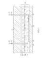
- FIG. 1shows a representation of target heavy oil reservoir with a horizontal well positioned near the bottom of the pay zone and a vertical injection well.
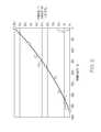
- FIG. 2is a graph of permeability in milli-darcies against total permeability for a typical heavy oil reservoir
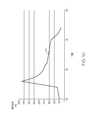
- FIG. 3is a graph of reservoir pressure vs. time for a sample reservoir according to the present invention.
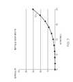
- FIG. 4shows a viscosity vs temperature graph for various solvent to oil ratios of solvent diluted heavy oil
- FIG. 5shows a plot of the vapour pressure of a specific solvent, ethane, as a function of volume fraction of ethane dissolved in a heavy oil, according to the present invention
- FIG. 6shows the time in days for the solvent to travel a specified distance through a heavy oil reservoir by dilution of the heavy oil according to the present invention
- FIG. 7shows a calculated oil production rate for an 800 m long horizontal well with 10 m of pay as a function of the degree of dilution of the solvent in oil for an average 1 Darcy permeability reservoir according to the present invention
- FIG. 8shows a calculated oil production rate for a 800 m long horizontal well with 10 m of pay as a function of the degree of dilution of the solvent in oil for an average 7 Darcy permeability reservoir according to the present invention
- FIG. 9shows the calculated solvent cost per cubic meter of oil recovered for the 7 Darcy heavy oil reservoir of FIG. 7 , as a function of the volume fraction of solvent in the oil (in this case ethane or C2) assuming the solvent is eventually recovered during the blowdown according to the present invention.
- FIG. 10shows the reservoir pressure versus time according to the present invention in the case where the solvent which is coproduced with the oil is not subsequently re-injected back into the reservoir;
- FIG. 11shows the calculated injection and production volumes as a function of time for the extraction process of the present invention when applied to a reservoir having an active aquifer or other type of pressure support, so that the reservoir pressure is effectively constrained to a constant value.
- This present inventionis most applicable to heavy oil reservoirs which have undergone a primary extraction and also which demonstrate good confinement.
- the primary extractionhas resulted in an oil extracted region in the reservoir having either gas or water filled voids.
- a preferred reservoirhas had a primary extraction which has recovered between about 5% and 25% of the original oil in place with a most preferred amount being between 8% and 15%.
- Most preferably a suitable target reservoirwill have a significant pay thickness without extensive horizontal barriers so that when the viscosity of the in situ heavy oil is sufficiently reduced, gravity drainage can occur.
- a primary extracted reservoiris preferred the present invention is also suitable for virgin reservoirs of the type having naturally occurring drainable voids having a volume of between about 5% and 25% of the original oil in place.
- An example of such a reservoiris one with a 20-40% water saturation and 60-80% oil saturation, but well confined reservoir in a porous formation.
- FIG. 1shows a schematic of a target oil reservoir with a vertical well 20 and a horizontal production well 22 .
- the horizontal well 22is generally placed near the bottom of pay zone 24 , and is a production well through which fluids draining through the reservoir by gravity drainage, can be removed.
- the typical pay zone 24has layers of different permeability shown as 28 , 30 , 32 , 34 , 36 , 38 , and 40 .
- Most preferably the pay zone 24is confined by an impermeable overburden layer 25 and an impermeable under burden layer 26 , but as will be appreciated by those skilled in the art of reservoir engineering, the present invention also comprehends that man made means for confinement can also be used.
- the pay zone 24has been produced using conventional primary extraction techniques, such as CHOPS (cold heavy oil production with sand), to the full extent possible which has left significant void volumes in what may be called an oil extracted zone.
- CHOPScold heavy oil production with sand
- the pay zone layers 28 to 40may be fairly uniform there are typically some permeability variations due to, for example, the original depositional process. There is also typically some natural variation in the oil quality and viscosity with position in the reservoir.
- the highest permeability zones in the pay zone 24in this case layers 30 and 38 will have been preferentially depleted of heavy oil, while the slightly less permeable zones 28 , 32 , 34 , 36 and 40 will have been mostly bypassed thus having higher proportions of “stranded oil”.
- the depleted regionswill likely also have some gas saturation as the naturally occurring in situ dissolved gas comes out of solution and fills the pores as the oil is removed.
- Significant water or brineis also likely to be present in the voids of the extracted oil regions of the pay zone, especially where waterflooding has been applied.
- Solventis being injected as shown by arrow 44 in vertical well 20 and a mixed solvent and oil blend 46 is being removed, for example by a pump 48 .
- FIG. 2shows with plot line 49 that an oil reservoir with a certain “average” permeability will typically encompass a large variety of different pore sizes and consequently will likely have a broad distribution of permeability that vary greatly from one pore to the next as well as from one layer to the next.
- any gas or liquid drive based extraction process(where gas or liquid pressure is used to try to push the oil out of the formation) is vulnerable to preferentially movement of the sweep fluid, such as solvent, through the largest and highest permeability pores first thereby bypassing significant amounts of oil contained in smaller and lower permeability pores.
- This bypassed oilwhich is not mobile at commercial recovery rates at reservoir conditions, is the stranded oil.
- FIG. 2shows that a significant portion of the oil will be stranded in lower permeability pores within the pay zone.
- FIG. 3shows the sequence of steps for an extraction process according to a preferred embodiment of the present invention as a series of changes to the reservoir pressure over time.
- FIG. 3shows the steps of voidage creation 50 , solvent charging 52 , ripening 54 , oil production 56 with simultaneous solvent recycle back into the formation and solvent blowdown 58 . Each of these preferred steps is discussed in more detail below.
- FIG. 3illustrates a schematic plot of the process of the present invention being applied to a reservoir where the solvent is ethane and the initial reservoir temperature is 20 C and rises to about 24 C (see FIG. 4 ) with assumed values for the reservoir porosity and the viscosity of the stranded heavy oil.
- the first step 50 of voidage creationoccurs as a pretreatment or conditioning step.
- Mobile fluids and gaseswhich for ease of understanding are referred to as solvent blockers, are pumped or produced from the reservoir.
- solvent blockersare pumped or produced from the reservoir.
- Most preferably these solvent blockerscan be extracted through existing wells that are left over from the primary extraction step, but in some cases it may be preferable to install a horizontal well towards the bottom of the formation and use that for removal of the solvent blockers.
- the most potent solvent blockersare believed to be water, brine and methane, all of which are likely present after the primary extraction process is no longer effective. Creation of additional voidage in the pay zone 24 can be further encouraged by introducing into the reservoir a relatively low pressure solvent vapour to remove as much solution gas and methane as possible.
- the preferred solventis ethane, although propane may also be suitable in certain reservoir conditions.
- the choice of solventwill depend on certain factors including both the effectiveness of the solvent at the pressure of the reservoir (which is often a function of the depth of the reservoir) and the cost at that time of the solvent on the open market. It is preferred to use ethane for reservoirs located below 1000 feet, and propane in reservoirs that are more shallow than that.
- the voidage creation of the present inventioncomprehends a series of displacement steps in an organized pattern to maximize recovery of water and methane gas from the pay zone 24 of the formation. As such the present invention will take advantage of whatever existing well configuration might be left over from primary extraction.
- Solvent purityis also an important aspect of the present invention.
- the more readily dissolving specieswill preferentially enter into solution with the oil, leaving the less readily dissolving species at the oil interface. Over a period of time therefore, the less soluble species becomes concentrated at the oil interface, and blocks the passage of the more readily dissolving solvent species into the oil, frustrating the process of dilution of the oil. Therefore, an aspect of the present invention is to replace relatively insoluble species, such as methane, that might be naturally present in the formation, with high concentrations of reasonably pure solvent such as ethane, or propane to prevent the less readily dissolving species from slowing down or preventing dilution.
- a solvent blockermay be either a gas or a liquid at reservoir conditions, and are advantageous to be removed.
- the voidage creation stepcan be done with or without pressure maintenance, depending on the reservoir conditions. In some cases it will be necessary to use pressure maintenance to minimize inflow from an active aquifer during the voidage creation and subsequent solvent charging step. In other cases, the reservoir may be sufficiently isolated and stable enough to not require any such pressure maintenance. However the present invention comprehends both types of voidage creation, depending upon which is most suitable for the specific reservoir conditions.
- the next step 52 in the present inventionis solvent charging. This involves continuing to introduce solvent, as a vapour, into the reservoir to carefully raise the pressure in the formation until it is above the bubble point pressure of the solvent vapour.
- solventas a vapour
- the present inventionattempts to extend the reach of the solvent into the furthest voids, and then by increasing the pressure above the bubble point, to fill all of the voidage volume created in the first step with liquid solvent. It is preferable to inject most of the solvent as a vapour to permit the solvent to easily penetrate the voids throughout the pay zone 24 without forming liquid or other barriers to further solvent penetration.
- the present inventioncomprehends that at the final stages of the injection the injection pressure will be high enough that most of the solvent is in a dense liquid like phase.
- solvent injection or chargingthere are several strategies for solvent injection or charging according to the present invention, depending upon the reservoir. Most preferably the solvent charging will occur in a way that permits the solvent to penetrate the voids created in the first step of the process. In some cases this is best accomplished by means of an existing vertical well that accesses a high permeability zone in the reservoir. It might also be preferable to use packers or the like in a vertical well to ensure that the solvent is being placed in an appropriate void zone in the reservoir. As well, if there is significant removal of blocking fluids from a sump by means of a horizontal well, then solvent may also be injected through the horizontal well.
- What is desired according to the present inventionis to place the solvent, as close as possible, to the voids created during the first step of the present invention, to try to fill those voids to fullest possible extent. Exactly how to do this will vary with the specific reservoir geology and characteristics but could be through one or more vertical wells and horizontal wells simultaneously.
- the next step of recovery according to the present inventionis a time delay or ripening step 54 in which sufficient time is provided for the solvent to slowly diffuse into the oil in the smaller less accessible pores, to dilute the oil contained therein and to reduce its viscosity such that the fully diluted or homogenized combination will be mobile within the formation.
- This homogenization processis also important to permit the oil to seep into the solvent filled pores, even as the solvent is seeping into the oil filled pores.
- Such a homogenization of the solvent in the oilwill according to the present invention help deter the solvent from bypassing the oil during the production phase.
- the ripening stepwill be characterized by a reservoir pressure that decays with time as the relatively pure solvent becomes diluted with oil and its vapour pressure is reduced.
- the present inventioncomprehends different ripening times for different reservoirs.
- One of the variablesis the diffusion distance, which in some cases can be estimated when the reservoir permeability and heterogeneity is known.
- the present inventionfurther comprehends being able to predict an optimum amount of time for the ripening step based on the reservoir heterogeneity and physical data about the oil. For example, the oil dilution rate will vary and a light oil with a high initial void fraction may achieve homogeneity within a short time, such as a day, but a high viscosity bitumen, with a low voidage (and solvent) distribution may require a long time, perhaps even decades.
- the present inventioncomprehends allowing the ripening step to progress to the maximum extent possible, given the conditions, such as void volume, to realize as much production as possible of the oil in place from the pay zone.
- the present inventionalso comprehends that while production can start from one area of the pay zone, slow solvent dilution of the oil can still be occurring in another area, and so it may not, in all cases, be necessary to wait until dilution has been maximized throughout the reservoir, to begin the recovery step, in cases where production in one part does affect ongoing solvent dilution in another part.
- the next step of the present inventionis a production step 56 .
- the production fluidswill be carefully monitored to determine if the solvent fraction exceeds this target fraction. If the liquid solvent volume fraction in the produced solvent/oil blend is larger than expected, then the solvent has not been successful at diluting all of the stranded oil that should be accessible to it and is likely bypassing significant amounts of oil. If the liquid solvent production rate is too high relative to the oil rate then the oil production rate can be restricted or the reservoir can be shut in again to allow the ripening step 54 further time to proceed towards more complete dilution.
- the oil production stepwill also co-produce solvent dissolved in the oil.
- this solventmay be recycled back into the formation or the solvent may be sold or shipped to a subsequent recovery project or even flared or burnt as fuel gas.
- the pressure, during productioncould also be augmented according to the present invention by solvent recycle or additional solvent injection if it was desirable to keep the solvent concentration in the oil high enough to reduce the oil viscosity to a particular target value.
- Thisoffers the possibility of increasing the solvent to oil ratio with time which might be helpful to maintain high oil production rates without excessive coning as the reservoir becomes depleted in oil.
- additional solvent injectionalso increases the risk of solvent de-asphalting and potential for formation damage. It may be desirable to inject a non-solvent fluid such as methane, nitrogen or the like for pressure maintenance towards the end of the production step, when adequate solvent is in the oil and solvent blocking across the interfacial area is no longer a concern.
- the final step in the extraction procedureis the solvent blowdown and recovery 58 . If there are pressure constraints such as an active aquifer it may be desirable to sweep the solvent out using another gas like methane, carbon dioxide or nitrogen.
- FIG. 4shows a viscosity graph for a typical heavy oil as a function of solvent dilution and temperature. This graph allows the viscosity reduction from the application of a particular quantity of solvent to a particular heavy oil to be estimated. The graph also shows that the viscosity of pure solvent may be 100,000 times lower than that of the native oil so the ripening step 54 giving the solvent enough time to dilute the oil is very important to avoid the solvent bypassing the oil. According to the present invention similar graphs can be constructed for other oil solvent combinations.
- the beginning of the arrows 60 and 62represents the viscosity of the pure unheated solvent and heavy oil reservoir fluid and the arrowheads show that the homogeneous oil solvent blend will have a viscosity just over one hundred centipoise.
- the graphshows a small temperature rise for this example due to the latent heat of condensation. However, it is clear in this particular case that the temperature rise does not provide a meaningful viscosity reduction.
- the graph of FIG. 4also permits the predicted viscosity to be assessed for the homogeneous solvent-oil blend at different solvent volume fractions. For example increasing the solvent volume to 20% would allow the blend viscosity to be dropped by a further factor of 10 to a value of about 13 cP.
- FIG. 5shows a curve 64 of the expected vapour pressure of a preferred solvent species ethane as a function of the volume fraction of ethane dissolved in the heavy oil.
- the saturation pressure for pure ethane at 24 Cis about 4100 kPa (absolute), so this is the level of injection pressure that is the minimum required to fill the voidage volume with liquid equivalent ethane.
- the total pressurewill be somewhat higher depending on the residual amount of methane remaining in voidage at the end of the first step of voidage creation. However, with a 10% volume fraction of ethane in the oil the ethane vapour pressure is only about 1600 kPa (absolute).
- the partial pressure of ethanewill drop from 4100 kPa (absolute) to about 1600 kPa (absolute).
- the reservoir pressurewill asymptote at a value that is about 2500 kPa below the injection pressure. As will be understood by those skilled in the art, this assumes that the reservoir is confined and that there is no pressure maintenance via an aquifer or gas cap.
- FIG. 6shows the approximate time required for the ripening step 54 as a function of the distance the solvent front must travel into the pay zone 24 for target reservoirs having in situ hydrocarbons ranging from bitumen to conventional oil, with the plots 70 for bitumen, 72 for heavy oil and 74 for conventional oil shown.
- This FIG. 6also shows the benefit of the initial voidage creation step 50 which increases the amount of solvent that can be safely injected into the target reservoir in step 52 , so that the distance the solvent must diffuse is reduced and the length of time required for the ripening step 54 is also reduced.
- doubling the amount of solvent from 10% to 20%might disperse the solvent more effectively in the target oil recovery zone and cut the ripening time in half.
- the conventional oil reservoir with the pay zone 24is assumed to contain 10 cP oil and have 100 millidarcies perm.
- the heavy oil reservoiris assumed to have 1 darcy permeability and oil viscosity of 10,000 cP and bitumen example is assumed to be 5 darcies permeability and 6 million cP bitumen.
- the duration of time for the ripening step 54is set by the speed that a concentration shock front will propagate through the reservoir. The propagation speed is derived from the correlation presented in the inventor's previous U.S. Pat. No. 2,591,354.
- FIG. 6also shows another curve 75 labeled stagnant countercurrent diffusion, which is a second way of estimating the solvent diffusion rate within the reservoir.
- the curve 75assumes that the solvent penetration or propagation distance is proportional to square root of ripening time for this estimation model.
- the countercurrent modelhas somewhat faster penetration rates at short distances and much slower penetration rates at longer distance for a particular heavy oil.
- the particular choice of solvent penetration rate modelrequires field calibration, one conclusion from both models, is that the solvent penetration time can be extremely long (years to decades) for relatively short propagation distances. Consequently, the benefits of the present invention, in getting a widespread dispersal of the solvent by removing solvent blockers, and to minimize the distance the solvent must travel to contact stranded heavy oil can now be appreciated.
- FIG. 7shows a plot 76 of the expected gravity drainage oil production rate for a 800 m long horizontal well with 10 m of pay for a heavy oil that is 10,000 cP at original reservoir conditions. This graph shows that for an average perm of 1 Darcy, the expected oil rate is only about 10 m3/day.
- FIG. 7shows the importance of achieving a sufficient concentration of solvent in the oil; doubling the solvent concentration from 10% to 20% by volume in the oil increases the oil production rate by 15 fold. Furthermore, solvent volume fractions below 10% appear to be totally futile.
- FIG. 8shows a plot 78 of the expected gravity drainage oil production rate for the same well and oil of FIG. 7 but having an average reservoir permeability of 7 Darcies.
- FIG. 8shows that a for a 10% volume solvent charge with average reservoir permeability of 7 Darcy, the expected oil recovery rate is as high as 100 m3/day.
- This figureshows that pay zones with higher permeability are highly preferred, for the present invention because they reduce the amount of solvent required to achieve a given production rate. It is preferred that most of the solvent be recovered and recycled, in which case the solvent cost can be largely recovered.
- FIG. 9depicts with plot 80 the calculated solvent cost for the 7 Darcy heavy oil reservoir of FIG. 8 , assuming the solvent is eventually recovered, either from the produced solvent/oil blend or during the final blowdown.
- FIG. 9shows that the solvent cost per m3 of oil production is reduced as the volume fraction of solvent increases in the produced solvent oil/blend. This is a surprising result and shows that the larger solvent inventory cost is more than offset by the reduced (faster) recovery time (based on the time value of money) to produce the stranded oil. Consequently, it shows that a process which aims to be frugal with the amount of solvent used, like much of the prior art, is not cost effective for maximizing value.
- FIG. 9further reinforces the benefit of the initial voidage creation step according to the present invention, which permits the volume of solvent is delivered in close proximity to the stranded oil to be maximized.
- FIG. 10shows a graph line 82 of the reservoir pressure versus time in the case where the solvent which is co-produced with the oil is not subsequently reinjected back into the reservoir formation.
- the reservoir pressuredeclines slightly over time during the production phase. It will be understood that this decline is not attributed to further dilution of the solvent into the oil, but rather by reason of the removal of the produced fluid volume from the pay zone in a well confined reservoir as taught by this invention.
- FIG. 11shows with plot 84 the cumulative solvent injection and production volumes as a function of time for the present invention when applied to a reservoir having an active aquifer or other type of pressure support.
- This type of reservoiris less desirable since the quality of the solvent dilution into oil and the appropriate ripening time cannot be assessed by means of remotely sensing the reservoir pressure because the reservoir pressure is effectively constrained at a constant value. It will be understood that the present extraction process invention can still be usefully applied to this type of reservoir but the assessment of the appropriate ripening time will be more uncertain, may rely more on the evaluation of the solvent to oil ratio of the produced fluids and will benefit from a detailed assessment of reservoir heterogeneity.
- the advantages of the present inventioncan now be more clearly understood.
- the volume of solvent introduced into the reservoiris maximized by the precondition step of the present invention, the solvent concentration in the produced fluid is quite small, as the primary and secondary recovery is frequently in the 10% to 20% range of the original oil in place. Consequently, the amount and value of the solvent that is co-produced with the oil is greatly reduced over other prior art processes such as 2,299,790.
- the present inventioncomprehends that it may be cost effective to completely ignore solvent recovery in some cases to minimize field plant capital cost.
- Another advantage of the present inventionis little or no asphaltene deposition is expected due to the relatively low solvent to oil ratio. On the other hand, little or no upgrading of the crude oil is expected.
- the present inventionis not a continuous process, as the full solvent charge is required almost from the start—during the ripening step no significant plant operating expenses are going to be incurred.
- FIG. 6shows that a ripening time of one month might allow a preferred solvent to propagate 5 meters in a conventional oil reservoir. However, it is expected that 6 or more years would be required for unheated solvent to diffuse 5 meters in very viscous bitumen of the oil sands. Additional commercial advantages include the potential of acquiring land with wells and production facilities for a low cost if a particular depleted heavy oil reservoir is perceived to be uneconomic to operate.
- Additional novel aspectsinclude, among other things, the following:
- the cleanup/decontamination stepto create void volume and get rid of undesirable contamination such as water and methane;
- the benefit of the present invention in using gravity drainageis that it can enable 60% or higher recovery of initial oil in place. If the primary only recovers 10% of the original oil in place then subsequent solvent assisted gravity drainage could allow 5 or more times cumulative oil production than was achieved in the primary and secondary production cycles.
- the reservoir pressureis dropped to 500 kPAa as solvent blockers consisting of water brine and methane are removed. Solvent vapour is then injected to help displace mobile water and methane from the reservoir and to permit the solvent vapour to spread out through the accessible reservoir voids.
- This drainage stepcreates a void volume of 15% of the pore space, which can be subsequently filled with solvent.
- Sufficient ethane solventis injected to fill this 15% void volume with liquid equivalent solvent (i.e. 270 kbbl liquid equivalent barrels of ethane).
- liquid equivalent solventi.e. 270 kbbl liquid equivalent barrels of ethane.
- the solventmust diffuse about 10 meters to homogenize across the full height of the reservoir. The required ripening time is estimated to be approximately one year.
- the reservoir pressureis measured until a decline from 4600 kPa to 3000 kPa is detected.
- the reservoiris then put on production via the horizontal well and the initial oil rate is calculated to be 250 m 3 /day (1500 bopd) or more.
- the production fluidsare carefully monitored to make sure that solvent isn't short circuiting. Assuming uniform solvent dilution of the stranded heavy oil, approximately 820,000 additional barrels of heavy oil are calculated to be available to be produced over the next 3 years. Towards the end of the production cycle the oil production rate will decline and the blowdown cycle is commenced to recover as much remaining solvent as can be had. At the end of the production cycle, it is calculated that each barrel of solvent injected has enabled the recovery of 3 additional barrels of oil. At current prices the ethane solvent cost is $13/bbl and the oil can be sold at $60 per barrel. Thus the solvent cost, with no solvent recovery at all, is about $4 per bbl of oil or ⁇ 6% of the oil value.
Landscapes
- Life Sciences & Earth Sciences (AREA)
- Engineering & Computer Science (AREA)
- Geology (AREA)
- Mining & Mineral Resources (AREA)
- Physics & Mathematics (AREA)
- Environmental & Geological Engineering (AREA)
- Fluid Mechanics (AREA)
- General Life Sciences & Earth Sciences (AREA)
- Geochemistry & Mineralogy (AREA)
- Geophysics (AREA)
- Production Of Liquid Hydrocarbon Mixture For Refining Petroleum (AREA)
- Extraction Or Liquid Replacement (AREA)
Abstract
Description
- a. Removing liquids and gases from areas in contact with said heavy oils to increase an interfacial area of unextracted heavy oil contactable by said solvent;
- b. Injecting said solvent in vapour form into said areas to raise the reservoir pressure until sufficient solvent is present in a liquid form to contact said increased interfacial area of said heavy oil;
- c. Shutting in said reservoir for a sufficient period of time to permit said solvent to diffuse into said unextracted oil across said interfacial area in a ripening step to create a reduced viscosity blend of solvent and oil;
- d. Measuring one or more reservoir characteristics to confirm the extent of solvent dilution that has occurred of the unextracted oil in the reservoir, and
- e. Commencing gravity drainage based production from said reservoir upon said blend having a viscosity low enough to permit said blend to drain through said reservoir to a production well.
Claims (21)
Applications Claiming Priority (3)
| Application Number | Priority Date | Filing Date | Title |
|---|---|---|---|
| CA2688937ACA2688937C (en) | 2009-12-21 | 2009-12-21 | A multi-step solvent extraction process for heavy oil reservoirs |
| CA2688937 | 2009-12-21 | ||
| PCT/CA2010/002030WO2011075835A1 (en) | 2009-12-21 | 2010-12-20 | A multi-step solvent extraction process for heavy oil reservoirs |
Publications (2)
| Publication Number | Publication Date |
|---|---|
| US20120267097A1 US20120267097A1 (en) | 2012-10-25 |
| US8985205B2true US8985205B2 (en) | 2015-03-24 |
Family
ID=44189445
Family Applications (1)
| Application Number | Title | Priority Date | Filing Date |
|---|---|---|---|
| US13/516,983Expired - Fee RelatedUS8985205B2 (en) | 2009-12-21 | 2010-12-20 | Multi-step solvent extraction process for heavy oil reservoirs |
Country Status (9)
| Country | Link |
|---|---|
| US (1) | US8985205B2 (en) |
| CN (1) | CN102667058B (en) |
| CA (1) | CA2688937C (en) |
| DE (1) | DE112010004901T5 (en) |
| GB (1) | GB2488943B (en) |
| MX (1) | MX2012007331A (en) |
| NO (1) | NO20120722A1 (en) |
| RU (1) | RU2547861C2 (en) |
| WO (1) | WO2011075835A1 (en) |
Cited By (5)
| Publication number | Priority date | Publication date | Assignee | Title |
|---|---|---|---|---|
| US10487636B2 (en) | 2017-07-27 | 2019-11-26 | Exxonmobil Upstream Research Company | Enhanced methods for recovering viscous hydrocarbons from a subterranean formation as a follow-up to thermal recovery processes |
| US11002123B2 (en) | 2017-08-31 | 2021-05-11 | Exxonmobil Upstream Research Company | Thermal recovery methods for recovering viscous hydrocarbons from a subterranean formation |
| US11142681B2 (en) | 2017-06-29 | 2021-10-12 | Exxonmobil Upstream Research Company | Chasing solvent for enhanced recovery processes |
| US11261725B2 (en) | 2017-10-24 | 2022-03-01 | Exxonmobil Upstream Research Company | Systems and methods for estimating and controlling liquid level using periodic shut-ins |
| US11377932B2 (en) | 2020-11-19 | 2022-07-05 | International Business Machines Corporation | Machine learning-based reservoir reserves estimation |
Families Citing this family (12)
| Publication number | Priority date | Publication date | Assignee | Title |
|---|---|---|---|---|
| CA2639851C (en) | 2008-09-26 | 2016-01-05 | Nsolv Corporation | A method of controlling growth and heat loss of an in situ gravity drainage chamber formed with a condensing solvent process |
| US20130087336A1 (en)* | 2011-10-05 | 2013-04-11 | Chevron U.S.A. Inc. | System And Method Of Perforating A Well And Preparing A Perforating Fluid For The Same |
| CN103244086B (en)* | 2013-04-12 | 2016-03-09 | 中国石油天然气股份有限公司 | In-situ regeneration foam oil exploitation method for deep heavy oil reservoir |
| CN104213886B (en)* | 2014-08-19 | 2016-08-31 | 中国石油天然气股份有限公司 | Heavy oil reservoir artificial foam oil huff and puff mining method |
| US10934822B2 (en) | 2016-03-23 | 2021-03-02 | Petrospec Engineering Inc. | Low-pressure method and apparatus of producing hydrocarbons from an underground formation using electric resistive heating and solvent injection |
| RU2625125C1 (en)* | 2016-06-11 | 2017-07-11 | Открытое акционерное общество "Татнефть" им. В.Д.Шашина | Excavation method of bituminic deposits with gas cap |
| RU2625127C1 (en)* | 2016-06-11 | 2017-07-11 | Открытое акционерное общество "Татнефть" им. В.Д.Шашина | Excavation method of high viscous oil deposits with gas cap |
| RU2663530C1 (en)* | 2017-07-07 | 2018-08-07 | Публичное акционерное общество "Татнефть" имени В.Д. Шашина | Method of development of deposits of high viscosity oil with the use of steam horizontal wells |
| RU2683015C1 (en)* | 2018-03-12 | 2019-03-25 | Общество с ограниченной ответственностью "Газпром проектирование" | Method for developing bituminous argillite and sandstone fields |
| RU2712904C1 (en)* | 2018-12-04 | 2020-01-31 | Публичное акционерное общество "Татнефть" имени В.Д. Шашина | Development method of ultraviscous oil deposit with gas cap |
| CN113982589B (en)* | 2021-10-26 | 2022-12-23 | 西安交通大学 | A temperature control method and system for in-situ mining of oil-rich coal |
| CN114607328A (en)* | 2022-04-11 | 2022-06-10 | 西南石油大学 | Method for exploiting thick oil by huff and puff through low-temperature oxidation air injection assisted by solvent |
Citations (73)
| Publication number | Priority date | Publication date | Assignee | Title |
|---|---|---|---|---|
| CA946737A (en) | 1971-10-26 | 1974-05-07 | William B. Braden (Jr.) | Oil recovery process |
| CA948987A (en) | 1972-01-17 | 1974-06-11 | Texaco Development Corporation | Method of treating a subterranean hydrocarbon-bearing formation |
| CA964577A (en) | 1971-09-30 | 1975-03-18 | Joseph C. Allen | Secondary recovery by miscible vertical drive |
| CA964996A (en) | 1971-09-27 | 1975-03-25 | Texaco Development Corporation | Secondary recovery for steeply dipping reservoirs: combined cellar and attic flooding |
| CA964997A (en) | 1971-09-27 | 1975-03-25 | Joseph C. Allen | Method for increasing the oil recovery from active water drive reservoirs |
| CA967873A (en) | 1972-03-29 | 1975-05-20 | Jack H. Kolaian | Secondary recovery method |
| CA967872A (en) | 1972-03-29 | 1975-05-20 | Charles A. Christopher | Secondary recovery method |
| CA971478A (en) | 1972-03-29 | 1975-07-22 | Charles A. Christopher | Secondary recovery method |
| CA981576A (en) | 1972-09-21 | 1976-01-13 | William B. Braden (Jr.) | Recovery of oil by a vertical miscible flood |
| CA982933A (en) | 1973-08-27 | 1976-02-03 | Joseph C. Allen | Recovery of hydrocarbons from a secondary gas cap by the injection of a light hydrocarbon |
| CA993792A (en) | 1972-12-22 | 1976-07-27 | Joseph T. Carlin | Tertiary recovery operation |
| CA1001068A (en) | 1973-05-04 | 1976-12-07 | Texaco Development Corporation | Vertical downward gas-driven miscible blanket flooding oil recovery process |
| CA1001067A (en) | 1973-05-04 | 1976-12-07 | David A. Redford | Method for recovering petroleum from viscous petroleum containing formations including tar sands |
| CA1001066A (en) | 1973-05-04 | 1976-12-07 | Texaco Development Corporation | Solution mining technique for tar sand deposits |
| CA1002871A (en) | 1973-05-04 | 1977-01-04 | Texaco Development Corporation | Miscible displacement of petroleum |
| CA1002874A (en) | 1973-05-04 | 1977-01-04 | Joseph C. Allen | Miscible displacement of petroleum |
| CA1002873A (en) | 1973-05-04 | 1977-01-04 | Texaco Development Corporation | Petroleum production technique |
| CA1002872A (en) | 1973-05-04 | 1977-01-04 | Joseph C. Allen | Petroleum recovery process |
| CA1003328A (en) | 1974-03-11 | 1977-01-11 | Joseph C. Allen | Recovery of viscous petroleum from asphaltic petroleum containing formations such as tar sand deposits |
| CA1005338A (en) | 1973-05-04 | 1977-02-15 | Texaco Development Corporation | Combined multiple solvent miscible flooding water injection technique for use in petroleum formations |
| CA1005339A (en) | 1973-05-04 | 1977-02-15 | Jack F. Tate | Multiple solvent miscible flooding technique for use in petroleum formation overlaying and in contact with water saturated, porous formations |
| CA1008361A (en) | 1973-08-24 | 1977-04-12 | Texaco Development Corporation | Method for recovering viscous oils by solvent extraction |
| CA1010361A (en) | 1973-09-28 | 1977-05-17 | David A. Redford | Recovery of petroleum from viscous petroleum containing formations including tar sand deposits |
| CA1010779A (en) | 1973-05-04 | 1977-05-24 | Joseph C. Allen | Solution mining technique for recovering bitumen from subsurface tar sand deposits |
| CA1011645A (en) | 1973-05-04 | 1977-06-07 | Texaco Development Corporation | Miscible displacement of petroleum |
| CA1011644A (en) | 1973-05-04 | 1977-06-07 | Joseph C. Allen | Vertical downward gas-driven miscible blanket flooding oil recovery process |
| CA1011647A (en) | 1973-10-15 | 1977-06-07 | Texaco Development Corporation | Multiple solvent heavy oil recovery method |
| CA1012884A (en) | 1974-06-24 | 1977-06-28 | Joseph C. Allen | Recovery of petroleum from viscous asphaltic petroleum containing formations including tar sand deposits |
| CA1016862A (en) | 1973-09-28 | 1977-09-06 | David A. Redford | Recovery of petroleum from viscous petroleum containing formations including tar sand deposits |
| CA1018058A (en) | 1973-10-15 | 1977-09-27 | Texaco Development Corporation | Combination solvent-noncondensible gas injection method for recovering petroleum from viscous petroleum-containing formations including tar sand deposits |
| CA1022843A (en) | 1974-03-01 | 1977-12-20 | Charles D. Woodward | Heated multiple solvent method for recovering viscous petroleum |
| CA1024066A (en) | 1974-03-07 | 1978-01-10 | Texaco Development Corporation | Carrier gas vaporized solvent oil recovery method |
| CA1027851A (en) | 1974-02-28 | 1978-03-14 | Texaco Development Corporation | Gaseous solvent heavy oil recovery method |
| CA1027850A (en) | 1973-10-15 | 1978-03-14 | David A. Redford | Method for establishing communication path in viscous petroleum-containing formations including tar sands for oil recovery operations |
| CA1056718A (en) | 1975-05-19 | 1979-06-19 | Joseph C. Allen | Recovery of bitumens by imbibition flooding |
| CA1060785A (en) | 1977-03-18 | 1979-08-21 | Texaco Development Corporation | Recovery of oil by a vertical miscible flood |
| CA1060784A (en) | 1976-06-23 | 1979-08-21 | Texaco Development Corporation | Method of in situ recovery of viscous oils and bitumens |
| CA1144064A (en) | 1979-10-29 | 1983-04-05 | Donald A. Best | Method for producing heavy crude |
| CA1145247A (en) | 1981-01-07 | 1983-04-26 | Joseph C. Allen | Miscible displacement oil recovery method |
| CA1148854A (en) | 1979-12-31 | 1983-06-28 | Joseph C. Allen | Method and apparatus for recovering high viscosity oils |
| CA1174163A (en) | 1981-04-10 | 1984-09-11 | Mobil Oil Corporation | Recovery of oil from tilted reservoirs |
| CA1192485A (en) | 1982-12-30 | 1985-08-27 | William C. Hunt, Iii | Solvent flooding to recover viscous oil |
| CA1194783A (en) | 1983-01-06 | 1985-10-08 | John L. Fitch | Method of recovering oil from a viscous oil- containing subsurface formation |
| CA1194784A (en) | 1983-01-11 | 1985-10-08 | Lynn D. Mullins | Cyclic solvent flooding to recover viscous oils |
| CA1197771A (en) | 1981-01-30 | 1985-12-10 | Harold S. Chung | Method for recovering heavy crudes from shallow reservoirs |
| CA1202881A (en) | 1983-01-07 | 1986-04-08 | John L. Fitch | Solvent flooding to recover viscous oils |
| CA1208539A (en) | 1983-01-17 | 1986-07-29 | James M. Mcmillen | Solvent stimulation of heavy oil reservoirs |
| CA1248014A (en) | 1985-02-22 | 1989-01-03 | Winston R. Shu | Miscible oil recovery process |
| CA2052202A1 (en) | 1990-10-01 | 1992-04-02 | John Nenniger | Method and apparatus for oil well stimulation |
| CA2155035A1 (en) | 1990-10-01 | 1992-04-02 | John Nenniger | Method and Apparatus for Oil Well Stimulation |
| CA2052558A1 (en) | 1990-01-11 | 1993-04-02 | Wann-Sheng Huang | Gas flooding with a horizontal well and two vertical wells |
| CA2127105A1 (en) | 1991-12-31 | 1993-07-08 | Henry L. Franke | Solvent extraction of oil from oil bearing materials |
| CA2108349A1 (en) | 1993-10-15 | 1993-11-15 | Roger M. Butler | Process and Apparatus for the Recovery of Hydrocarbons from a Hydrocarbon Deposit |
| CA2147079A1 (en) | 1995-04-13 | 1996-10-14 | Roger M. Butler | Process and apparatus for the recovery of hydrocarbons from a reservoir of hydrocarbons |
| CA2185837A1 (en) | 1996-09-18 | 1998-03-19 | Alberta Oil Sands Technology And Research Authority | Solvent-assisted method for mobilizing viscous heavy oil |
| CA2243105A1 (en) | 1998-07-10 | 1999-08-15 | Igor J. Mokrys | Vapour extraction of hydrocarbon deposits |
| CA2567399A1 (en) | 1998-04-17 | 1999-10-17 | N-Solv Corporation | Method and apparatus for stimulating heavy oil production |
| CA2347786A1 (en) | 1998-11-03 | 2000-05-11 | Exxonmobil Upstream Research Company | Method to reduce water saturation in near-well region |
| CA2270703A1 (en) | 1999-04-29 | 2000-10-29 | Alberta Energy Company Ltd. | A process for non-thermal vapor extraction of viscous oil from a hydrocarbon reservoir using a vertical well configuration |
| CA2389760A1 (en) | 1999-11-01 | 2001-05-10 | Enhanced Recovery Systems Limited | Composition and process for oil extraction |
| CA2633061A1 (en) | 2000-02-23 | 2001-08-23 | Nsolv Corporation | Method and apparatus for stimulating heavy oil production |
| US6357526B1 (en)* | 2000-03-16 | 2002-03-19 | Kellogg Brown & Root, Inc. | Field upgrading of heavy oil and bitumen |
| CA2349234A1 (en) | 2001-05-31 | 2002-11-30 | Imperial Oil Resources Limited | Cyclic solvent process for in-situ bitumen and heavy oil production |
| CA2351148A1 (en) | 2001-06-21 | 2002-12-21 | John Nenniger | Method and apparatus for stimulating heavy oil production |
| CA2462359A1 (en) | 2004-03-24 | 2005-09-24 | Imperial Oil Resources Limited | Process for in situ recovery of bitumen and heavy oil |
| CA2560851A1 (en) | 2004-03-25 | 2005-10-13 | University Of Wyoming | Method for increasing the production of hydrocarbon liquids and gases |
| CA2494391A1 (en) | 2005-01-26 | 2006-07-26 | Nexen, Inc. | Methods of improving heavy oil production |
| CA2647973A1 (en) | 2006-03-29 | 2007-10-04 | Geosierra Llc | Enhanced hydrocarbon recovery by vaporizing solvents in oil sand formations |
| CA2553297A1 (en) | 2006-07-21 | 2008-01-21 | Paramount Resources Ltd. | In situ process to recover heavy oil and bitumen |
| CA2672487A1 (en) | 2006-12-13 | 2008-06-19 | Stephen Richard Larter | Preconditioning an oilfield reservoir |
| CA2630682A1 (en) | 2006-12-22 | 2008-06-22 | Petroleo Brasileiro S.A. - Petrobras | Sustainable method for recovery of petroleum |
| CA2584712A1 (en) | 2007-04-13 | 2008-10-13 | Nexen Inc. | Methods of improving heavy oil production |
| US7562708B2 (en)* | 2006-05-10 | 2009-07-21 | Raytheon Company | Method and apparatus for capture and sequester of carbon dioxide and extraction of energy from large land masses during and after extraction of hydrocarbon fuels or contaminants using energy and critical fluids |
Family Cites Families (9)
| Publication number | Priority date | Publication date | Assignee | Title |
|---|---|---|---|---|
| US4373585A (en)* | 1981-07-21 | 1983-02-15 | Mobil Oil Corporation | Method of solvent flooding to recover viscous oils |
| US4373586A (en)* | 1981-08-07 | 1983-02-15 | Mobil Oil Corporation | Method of solvent flooding to recover viscous oils |
| US4510997A (en)* | 1981-10-05 | 1985-04-16 | Mobil Oil Corporation | Solvent flooding to recover viscous oils |
| US4385662A (en)* | 1981-10-05 | 1983-05-31 | Mobil Oil Corporation | Method of cyclic solvent flooding to recover viscous oils |
| SU1295803A1 (en)* | 1985-03-15 | 1997-10-27 | Башкирский государственный университет им.40-летия Октября | Method for development of oil deposit with bottom water |
| CA2046107C (en)* | 1991-07-03 | 1994-12-06 | Geryl Owen Brannan | Laterally and vertically staggered horizontal well hydrocarbon recovery method |
| US5720350A (en) | 1996-05-03 | 1998-02-24 | Atlantic Richfield Company | Method for recovering oil from a gravity drainage formation |
| US5948242A (en)* | 1997-10-15 | 1999-09-07 | Unipure Corporation | Process for upgrading heavy crude oil production |
| RU2274742C1 (en)* | 2005-06-07 | 2006-04-20 | Открытое акционерное общество "Татнефть" им. В.Д. Шашина | Method for high-viscous oil or bitumen field development |
- 2009
- 2009-12-21CACA2688937Apatent/CA2688937C/ennot_activeExpired - Fee Related
- 2010
- 2010-12-20WOPCT/CA2010/002030patent/WO2011075835A1/enactiveApplication Filing
- 2010-12-20MXMX2012007331Apatent/MX2012007331A/enactiveIP Right Grant
- 2010-12-20USUS13/516,983patent/US8985205B2/ennot_activeExpired - Fee Related
- 2010-12-20RURU2012129363/03Apatent/RU2547861C2/ennot_activeIP Right Cessation
- 2010-12-20CNCN201080059093.5Apatent/CN102667058B/ennot_activeExpired - Fee Related
- 2010-12-20GBGB1211152.2Apatent/GB2488943B/ennot_activeExpired - Fee Related
- 2010-12-20DEDE112010004901Tpatent/DE112010004901T5/ennot_activeWithdrawn
- 2012
- 2012-06-21NONO20120722Apatent/NO20120722A1/ennot_activeApplication Discontinuation
Patent Citations (75)
| Publication number | Priority date | Publication date | Assignee | Title |
|---|---|---|---|---|
| CA964996A (en) | 1971-09-27 | 1975-03-25 | Texaco Development Corporation | Secondary recovery for steeply dipping reservoirs: combined cellar and attic flooding |
| CA964997A (en) | 1971-09-27 | 1975-03-25 | Joseph C. Allen | Method for increasing the oil recovery from active water drive reservoirs |
| CA964577A (en) | 1971-09-30 | 1975-03-18 | Joseph C. Allen | Secondary recovery by miscible vertical drive |
| CA946737A (en) | 1971-10-26 | 1974-05-07 | William B. Braden (Jr.) | Oil recovery process |
| CA948987A (en) | 1972-01-17 | 1974-06-11 | Texaco Development Corporation | Method of treating a subterranean hydrocarbon-bearing formation |
| CA967873A (en) | 1972-03-29 | 1975-05-20 | Jack H. Kolaian | Secondary recovery method |
| CA967872A (en) | 1972-03-29 | 1975-05-20 | Charles A. Christopher | Secondary recovery method |
| CA971478A (en) | 1972-03-29 | 1975-07-22 | Charles A. Christopher | Secondary recovery method |
| CA981576A (en) | 1972-09-21 | 1976-01-13 | William B. Braden (Jr.) | Recovery of oil by a vertical miscible flood |
| CA993792A (en) | 1972-12-22 | 1976-07-27 | Joseph T. Carlin | Tertiary recovery operation |
| CA1002873A (en) | 1973-05-04 | 1977-01-04 | Texaco Development Corporation | Petroleum production technique |
| CA1002872A (en) | 1973-05-04 | 1977-01-04 | Joseph C. Allen | Petroleum recovery process |
| CA1001067A (en) | 1973-05-04 | 1976-12-07 | David A. Redford | Method for recovering petroleum from viscous petroleum containing formations including tar sands |
| CA1001066A (en) | 1973-05-04 | 1976-12-07 | Texaco Development Corporation | Solution mining technique for tar sand deposits |
| CA1002871A (en) | 1973-05-04 | 1977-01-04 | Texaco Development Corporation | Miscible displacement of petroleum |
| CA1002874A (en) | 1973-05-04 | 1977-01-04 | Joseph C. Allen | Miscible displacement of petroleum |
| CA1011644A (en) | 1973-05-04 | 1977-06-07 | Joseph C. Allen | Vertical downward gas-driven miscible blanket flooding oil recovery process |
| CA1001068A (en) | 1973-05-04 | 1976-12-07 | Texaco Development Corporation | Vertical downward gas-driven miscible blanket flooding oil recovery process |
| CA1011645A (en) | 1973-05-04 | 1977-06-07 | Texaco Development Corporation | Miscible displacement of petroleum |
| CA1005338A (en) | 1973-05-04 | 1977-02-15 | Texaco Development Corporation | Combined multiple solvent miscible flooding water injection technique for use in petroleum formations |
| CA1005339A (en) | 1973-05-04 | 1977-02-15 | Jack F. Tate | Multiple solvent miscible flooding technique for use in petroleum formation overlaying and in contact with water saturated, porous formations |
| CA1010779A (en) | 1973-05-04 | 1977-05-24 | Joseph C. Allen | Solution mining technique for recovering bitumen from subsurface tar sand deposits |
| CA1008361A (en) | 1973-08-24 | 1977-04-12 | Texaco Development Corporation | Method for recovering viscous oils by solvent extraction |
| CA982933A (en) | 1973-08-27 | 1976-02-03 | Joseph C. Allen | Recovery of hydrocarbons from a secondary gas cap by the injection of a light hydrocarbon |
| CA1010361A (en) | 1973-09-28 | 1977-05-17 | David A. Redford | Recovery of petroleum from viscous petroleum containing formations including tar sand deposits |
| CA1016862A (en) | 1973-09-28 | 1977-09-06 | David A. Redford | Recovery of petroleum from viscous petroleum containing formations including tar sand deposits |
| CA1011647A (en) | 1973-10-15 | 1977-06-07 | Texaco Development Corporation | Multiple solvent heavy oil recovery method |
| CA1027850A (en) | 1973-10-15 | 1978-03-14 | David A. Redford | Method for establishing communication path in viscous petroleum-containing formations including tar sands for oil recovery operations |
| CA1018058A (en) | 1973-10-15 | 1977-09-27 | Texaco Development Corporation | Combination solvent-noncondensible gas injection method for recovering petroleum from viscous petroleum-containing formations including tar sand deposits |
| CA1027851A (en) | 1974-02-28 | 1978-03-14 | Texaco Development Corporation | Gaseous solvent heavy oil recovery method |
| CA1022843A (en) | 1974-03-01 | 1977-12-20 | Charles D. Woodward | Heated multiple solvent method for recovering viscous petroleum |
| CA1024066A (en) | 1974-03-07 | 1978-01-10 | Texaco Development Corporation | Carrier gas vaporized solvent oil recovery method |
| CA1003328A (en) | 1974-03-11 | 1977-01-11 | Joseph C. Allen | Recovery of viscous petroleum from asphaltic petroleum containing formations such as tar sand deposits |
| CA1012884A (en) | 1974-06-24 | 1977-06-28 | Joseph C. Allen | Recovery of petroleum from viscous asphaltic petroleum containing formations including tar sand deposits |
| CA1056718A (en) | 1975-05-19 | 1979-06-19 | Joseph C. Allen | Recovery of bitumens by imbibition flooding |
| CA1060784A (en) | 1976-06-23 | 1979-08-21 | Texaco Development Corporation | Method of in situ recovery of viscous oils and bitumens |
| CA1060785A (en) | 1977-03-18 | 1979-08-21 | Texaco Development Corporation | Recovery of oil by a vertical miscible flood |
| CA1144064A (en) | 1979-10-29 | 1983-04-05 | Donald A. Best | Method for producing heavy crude |
| CA1148854A (en) | 1979-12-31 | 1983-06-28 | Joseph C. Allen | Method and apparatus for recovering high viscosity oils |
| CA1145247A (en) | 1981-01-07 | 1983-04-26 | Joseph C. Allen | Miscible displacement oil recovery method |
| CA1197771A (en) | 1981-01-30 | 1985-12-10 | Harold S. Chung | Method for recovering heavy crudes from shallow reservoirs |
| CA1174163A (en) | 1981-04-10 | 1984-09-11 | Mobil Oil Corporation | Recovery of oil from tilted reservoirs |
| CA1192485A (en) | 1982-12-30 | 1985-08-27 | William C. Hunt, Iii | Solvent flooding to recover viscous oil |
| CA1194783A (en) | 1983-01-06 | 1985-10-08 | John L. Fitch | Method of recovering oil from a viscous oil- containing subsurface formation |
| CA1202881A (en) | 1983-01-07 | 1986-04-08 | John L. Fitch | Solvent flooding to recover viscous oils |
| CA1194784A (en) | 1983-01-11 | 1985-10-08 | Lynn D. Mullins | Cyclic solvent flooding to recover viscous oils |
| CA1208539A (en) | 1983-01-17 | 1986-07-29 | James M. Mcmillen | Solvent stimulation of heavy oil reservoirs |
| CA1248014A (en) | 1985-02-22 | 1989-01-03 | Winston R. Shu | Miscible oil recovery process |
| CA2052558A1 (en) | 1990-01-11 | 1993-04-02 | Wann-Sheng Huang | Gas flooding with a horizontal well and two vertical wells |
| CA2052202A1 (en) | 1990-10-01 | 1992-04-02 | John Nenniger | Method and apparatus for oil well stimulation |
| CA2155035A1 (en) | 1990-10-01 | 1992-04-02 | John Nenniger | Method and Apparatus for Oil Well Stimulation |
| CA2127105A1 (en) | 1991-12-31 | 1993-07-08 | Henry L. Franke | Solvent extraction of oil from oil bearing materials |
| CA2108349A1 (en) | 1993-10-15 | 1993-11-15 | Roger M. Butler | Process and Apparatus for the Recovery of Hydrocarbons from a Hydrocarbon Deposit |
| CA2147079A1 (en) | 1995-04-13 | 1996-10-14 | Roger M. Butler | Process and apparatus for the recovery of hydrocarbons from a reservoir of hydrocarbons |
| CA2185837A1 (en) | 1996-09-18 | 1998-03-19 | Alberta Oil Sands Technology And Research Authority | Solvent-assisted method for mobilizing viscous heavy oil |
| CA2235085A1 (en) | 1998-04-17 | 1999-10-17 | John Nenniger | Method and apparatus for stimulating heavy oil production |
| CA2567399A1 (en) | 1998-04-17 | 1999-10-17 | N-Solv Corporation | Method and apparatus for stimulating heavy oil production |
| CA2243105A1 (en) | 1998-07-10 | 1999-08-15 | Igor J. Mokrys | Vapour extraction of hydrocarbon deposits |
| CA2347786A1 (en) | 1998-11-03 | 2000-05-11 | Exxonmobil Upstream Research Company | Method to reduce water saturation in near-well region |
| CA2270703A1 (en) | 1999-04-29 | 2000-10-29 | Alberta Energy Company Ltd. | A process for non-thermal vapor extraction of viscous oil from a hydrocarbon reservoir using a vertical well configuration |
| CA2389760A1 (en) | 1999-11-01 | 2001-05-10 | Enhanced Recovery Systems Limited | Composition and process for oil extraction |
| CA2633061A1 (en) | 2000-02-23 | 2001-08-23 | Nsolv Corporation | Method and apparatus for stimulating heavy oil production |
| CA2299790A1 (en) | 2000-02-23 | 2001-08-23 | John Nenniger | Method and apparatus for stimulating heavy oil production |
| US6357526B1 (en)* | 2000-03-16 | 2002-03-19 | Kellogg Brown & Root, Inc. | Field upgrading of heavy oil and bitumen |
| CA2349234A1 (en) | 2001-05-31 | 2002-11-30 | Imperial Oil Resources Limited | Cyclic solvent process for in-situ bitumen and heavy oil production |
| CA2351148A1 (en) | 2001-06-21 | 2002-12-21 | John Nenniger | Method and apparatus for stimulating heavy oil production |
| CA2462359A1 (en) | 2004-03-24 | 2005-09-24 | Imperial Oil Resources Limited | Process for in situ recovery of bitumen and heavy oil |
| CA2560851A1 (en) | 2004-03-25 | 2005-10-13 | University Of Wyoming | Method for increasing the production of hydrocarbon liquids and gases |
| CA2494391A1 (en) | 2005-01-26 | 2006-07-26 | Nexen, Inc. | Methods of improving heavy oil production |
| CA2647973A1 (en) | 2006-03-29 | 2007-10-04 | Geosierra Llc | Enhanced hydrocarbon recovery by vaporizing solvents in oil sand formations |
| US7562708B2 (en)* | 2006-05-10 | 2009-07-21 | Raytheon Company | Method and apparatus for capture and sequester of carbon dioxide and extraction of energy from large land masses during and after extraction of hydrocarbon fuels or contaminants using energy and critical fluids |
| CA2553297A1 (en) | 2006-07-21 | 2008-01-21 | Paramount Resources Ltd. | In situ process to recover heavy oil and bitumen |
| CA2672487A1 (en) | 2006-12-13 | 2008-06-19 | Stephen Richard Larter | Preconditioning an oilfield reservoir |
| CA2630682A1 (en) | 2006-12-22 | 2008-06-22 | Petroleo Brasileiro S.A. - Petrobras | Sustainable method for recovery of petroleum |
| CA2584712A1 (en) | 2007-04-13 | 2008-10-13 | Nexen Inc. | Methods of improving heavy oil production |
Cited By (5)
| Publication number | Priority date | Publication date | Assignee | Title |
|---|---|---|---|---|
| US11142681B2 (en) | 2017-06-29 | 2021-10-12 | Exxonmobil Upstream Research Company | Chasing solvent for enhanced recovery processes |
| US10487636B2 (en) | 2017-07-27 | 2019-11-26 | Exxonmobil Upstream Research Company | Enhanced methods for recovering viscous hydrocarbons from a subterranean formation as a follow-up to thermal recovery processes |
| US11002123B2 (en) | 2017-08-31 | 2021-05-11 | Exxonmobil Upstream Research Company | Thermal recovery methods for recovering viscous hydrocarbons from a subterranean formation |
| US11261725B2 (en) | 2017-10-24 | 2022-03-01 | Exxonmobil Upstream Research Company | Systems and methods for estimating and controlling liquid level using periodic shut-ins |
| US11377932B2 (en) | 2020-11-19 | 2022-07-05 | International Business Machines Corporation | Machine learning-based reservoir reserves estimation |
Also Published As
| Publication number | Publication date |
|---|---|
| GB201211152D0 (en) | 2012-08-08 |
| RU2547861C2 (en) | 2015-04-10 |
| NO20120722A1 (en) | 2012-09-11 |
| WO2011075835A1 (en) | 2011-06-30 |
| RU2012129363A (en) | 2014-01-27 |
| CN102667058B (en) | 2015-10-07 |
| GB2488943B (en) | 2015-09-23 |
| GB2488943A (en) | 2012-09-12 |
| DE112010004901T5 (en) | 2012-11-15 |
| MX2012007331A (en) | 2012-11-06 |
| CN102667058A (en) | 2012-09-12 |
| US20120267097A1 (en) | 2012-10-25 |
| CA2688937C (en) | 2017-08-15 |
| CA2688937A1 (en) | 2011-06-21 |
Similar Documents
| Publication | Publication Date | Title |
|---|---|---|
| US8985205B2 (en) | Multi-step solvent extraction process for heavy oil reservoirs | |
| US9488040B2 (en) | Cyclic solvent hydrocarbon recovery process using an advance-retreat movement of the injectant | |
| US20120325467A1 (en) | Method of Controlling Solvent Injection To Aid Recovery of Hydrocarbons From An Underground Reservoir | |
| Coskuner et al. | An enhanced oil recovery technology as a follow up to cold heavy oil production with sand | |
| US20140000886A1 (en) | Petroleum recovery process and system | |
| Vega Riveros et al. | Steam injection experiences in heavy and extra-heavy oil fields, Venezuela | |
| CN105940080A (en) | Production stimulation methods and systems for increasing crude oil production | |
| US10190400B2 (en) | Solvent injection recovery process | |
| US20120234535A1 (en) | Method Of Injecting Solvent Into An Underground Reservoir To Aid Recovery Of Hydrocarbons | |
| Delamaide et al. | Enhanced oil recovery of heavy oil in reservoirs with bottom aquifer | |
| US8616278B2 (en) | Creation of a hydrate barrier during in situ hydrocarbon recovery | |
| Jiang et al. | Evaluation of recovery technologies for the Grosmont carbonate reservoirs | |
| US9328592B2 (en) | Steam anti-coning/cresting technology ( SACT) remediation process | |
| Davis et al. | Using Foam Treatments to Control Gas-Oil Ratio in Horizontal Producing Wells at Prudhoe Bay | |
| Firouz | Applicability of solvent based Huff-and-Puff Method to enhance heavy oil recovery | |
| Shaheen et al. | World's First Combination of Acid & Steam Provides A New Dimension To Heavy Oil Enhanced Recovery Process | |
| Zhang | Cyclic hot solvent injection method to enhance heavy oil recovery based on experimental study | |
| CA2971206A1 (en) | Blowdown pressure maintenance with foam | |
| Ji | Simulation Study of Steam-Solvent Phase Behaviour in Solvent Aided SAGD Process and Its Effect on Oil Recovery | |
| Berg et al. | Heavy Oil Offshore UK: Recommended Mariner Reservoir Development Strategy | |
| Seyyedsar | Enhanced heavy oil recovery by CO2 injection | |
| Belovus et al. | The Application of Foam and Gel Compositions to Control Gas Inflow in Production Wells: From Laboratory Studies to Injection | |
| CA3097200A1 (en) | Dimethyl ether-based method for recovering viscous oil from a water-wet reservoir | |
| Naderi | Heavy Oil/Bitumen Recovery by Alternate Injection of Steam and Solvent (Hydrocarbon and CO 2) in Fractured Carbonates and Oilsands | |
| Lee | Numerical simulation techniques in heavy oil carbonate reservoirs |
Legal Events
| Date | Code | Title | Description |
|---|---|---|---|
| AS | Assignment | Owner name:N-SOLV CORPORATION, CANADA Free format text:ASSIGNMENT OF ASSIGNORS INTEREST;ASSIGNOR:NENNIGER, JOHN;REEL/FRAME:028428/0709 Effective date:20091221 Owner name:N-SOLV HEAVY OIL CORPORATION, CANADA Free format text:ASSIGNMENT OF ASSIGNORS INTEREST;ASSIGNOR:N-SOLV CORPORATION;REEL/FRAME:028429/0128 Effective date:20101015 | |
| STCF | Information on status: patent grant | Free format text:PATENTED CASE | |
| MAFP | Maintenance fee payment | Free format text:PAYMENT OF MAINTENANCE FEE, 4TH YR, SMALL ENTITY (ORIGINAL EVENT CODE: M2551); ENTITY STATUS OF PATENT OWNER: SMALL ENTITY Year of fee payment:4 | |
| FEPP | Fee payment procedure | Free format text:MAINTENANCE FEE REMINDER MAILED (ORIGINAL EVENT CODE: REM.); ENTITY STATUS OF PATENT OWNER: SMALL ENTITY | |
| LAPS | Lapse for failure to pay maintenance fees | Free format text:PATENT EXPIRED FOR FAILURE TO PAY MAINTENANCE FEES (ORIGINAL EVENT CODE: EXP.); ENTITY STATUS OF PATENT OWNER: SMALL ENTITY | |
| STCH | Information on status: patent discontinuation | Free format text:PATENT EXPIRED DUE TO NONPAYMENT OF MAINTENANCE FEES UNDER 37 CFR 1.362 | |
| FP | Lapsed due to failure to pay maintenance fee | Effective date:20230324 |