US8985116B2 - Layered nasal devices - Google Patents
Layered nasal devicesDownload PDFInfo
- Publication number
- US8985116B2 US8985116B2US11/759,916US75991607AUS8985116B2US 8985116 B2US8985116 B2US 8985116B2US 75991607 AUS75991607 AUS 75991607AUS 8985116 B2US8985116 B2US 8985116B2
- Authority
- US
- United States
- Prior art keywords
- adhesive
- flap valve
- layer
- nasal
- layered
- Prior art date
- Legal status (The legal status is an assumption and is not a legal conclusion. Google has not performed a legal analysis and makes no representation as to the accuracy of the status listed.)
- Expired - Fee Related, expires
Links
Images


Classifications
- A—HUMAN NECESSITIES
- A62—LIFE-SAVING; FIRE-FIGHTING
- A62B—DEVICES, APPARATUS OR METHODS FOR LIFE-SAVING
- A62B23/00—Filters for breathing-protection purposes
- A62B23/02—Filters for breathing-protection purposes for respirators
- A—HUMAN NECESSITIES
- A62—LIFE-SAVING; FIRE-FIGHTING
- A62B—DEVICES, APPARATUS OR METHODS FOR LIFE-SAVING
- A62B23/00—Filters for breathing-protection purposes
- A62B23/06—Nose filters
- A—HUMAN NECESSITIES
- A61—MEDICAL OR VETERINARY SCIENCE; HYGIENE
- A61M—DEVICES FOR INTRODUCING MEDIA INTO, OR ONTO, THE BODY; DEVICES FOR TRANSDUCING BODY MEDIA OR FOR TAKING MEDIA FROM THE BODY; DEVICES FOR PRODUCING OR ENDING SLEEP OR STUPOR
- A61M15/00—Inhalators
- A61M15/08—Inhaling devices inserted into the nose
- A61M15/085—Fixing means therefor
- A—HUMAN NECESSITIES
- A61—MEDICAL OR VETERINARY SCIENCE; HYGIENE
- A61M—DEVICES FOR INTRODUCING MEDIA INTO, OR ONTO, THE BODY; DEVICES FOR TRANSDUCING BODY MEDIA OR FOR TAKING MEDIA FROM THE BODY; DEVICES FOR PRODUCING OR ENDING SLEEP OR STUPOR
- A61M16/00—Devices for influencing the respiratory system of patients by gas treatment, e.g. ventilators; Tracheal tubes
- A61M16/06—Respiratory or anaesthetic masks
- A61M16/0605—Means for improving the adaptation of the mask to the patient
- A61M16/0616—Means for improving the adaptation of the mask to the patient with face sealing means comprising a flap or membrane projecting inwards, such that sealing increases with increasing inhalation gas pressure
- A—HUMAN NECESSITIES
- A61—MEDICAL OR VETERINARY SCIENCE; HYGIENE
- A61M—DEVICES FOR INTRODUCING MEDIA INTO, OR ONTO, THE BODY; DEVICES FOR TRANSDUCING BODY MEDIA OR FOR TAKING MEDIA FROM THE BODY; DEVICES FOR PRODUCING OR ENDING SLEEP OR STUPOR
- A61M16/00—Devices for influencing the respiratory system of patients by gas treatment, e.g. ventilators; Tracheal tubes
- A61M16/06—Respiratory or anaesthetic masks
- A61M16/0683—Holding devices therefor
- A61M16/0688—Holding devices therefor by means of an adhesive
- A—HUMAN NECESSITIES
- A61—MEDICAL OR VETERINARY SCIENCE; HYGIENE
- A61M—DEVICES FOR INTRODUCING MEDIA INTO, OR ONTO, THE BODY; DEVICES FOR TRANSDUCING BODY MEDIA OR FOR TAKING MEDIA FROM THE BODY; DEVICES FOR PRODUCING OR ENDING SLEEP OR STUPOR
- A61M16/00—Devices for influencing the respiratory system of patients by gas treatment, e.g. ventilators; Tracheal tubes
- A61M16/08—Bellows; Connecting tubes ; Water traps; Patient circuits
- A61M16/0866—Passive resistors therefor
- A—HUMAN NECESSITIES
- A61—MEDICAL OR VETERINARY SCIENCE; HYGIENE
- A61M—DEVICES FOR INTRODUCING MEDIA INTO, OR ONTO, THE BODY; DEVICES FOR TRANSDUCING BODY MEDIA OR FOR TAKING MEDIA FROM THE BODY; DEVICES FOR PRODUCING OR ENDING SLEEP OR STUPOR
- A61M16/00—Devices for influencing the respiratory system of patients by gas treatment, e.g. ventilators; Tracheal tubes
- A61M16/10—Preparation of respiratory gases or vapours
- A61M16/105—Filters
- A61M16/106—Filters in a path
- A—HUMAN NECESSITIES
- A61—MEDICAL OR VETERINARY SCIENCE; HYGIENE
- A61M—DEVICES FOR INTRODUCING MEDIA INTO, OR ONTO, THE BODY; DEVICES FOR TRANSDUCING BODY MEDIA OR FOR TAKING MEDIA FROM THE BODY; DEVICES FOR PRODUCING OR ENDING SLEEP OR STUPOR
- A61M16/00—Devices for influencing the respiratory system of patients by gas treatment, e.g. ventilators; Tracheal tubes
- A61M16/20—Valves specially adapted to medical respiratory devices
- A61M16/208—Non-controlled one-way valves, e.g. exhalation, check, pop-off non-rebreathing valves
- A—HUMAN NECESSITIES
- A61—MEDICAL OR VETERINARY SCIENCE; HYGIENE
- A61F—FILTERS IMPLANTABLE INTO BLOOD VESSELS; PROSTHESES; DEVICES PROVIDING PATENCY TO, OR PREVENTING COLLAPSING OF, TUBULAR STRUCTURES OF THE BODY, e.g. STENTS; ORTHOPAEDIC, NURSING OR CONTRACEPTIVE DEVICES; FOMENTATION; TREATMENT OR PROTECTION OF EYES OR EARS; BANDAGES, DRESSINGS OR ABSORBENT PADS; FIRST-AID KITS
- A61F5/00—Orthopaedic methods or devices for non-surgical treatment of bones or joints; Nursing devices ; Anti-rape devices
- A61F5/01—Orthopaedic devices, e.g. long-term immobilising or pressure directing devices for treating broken or deformed bones such as splints, casts or braces
- A61F5/08—Devices for correcting deformities of the nose ; Devices for enlarging the nostril, e.g. for breathing improvement
- A—HUMAN NECESSITIES
- A61—MEDICAL OR VETERINARY SCIENCE; HYGIENE
- A61F—FILTERS IMPLANTABLE INTO BLOOD VESSELS; PROSTHESES; DEVICES PROVIDING PATENCY TO, OR PREVENTING COLLAPSING OF, TUBULAR STRUCTURES OF THE BODY, e.g. STENTS; ORTHOPAEDIC, NURSING OR CONTRACEPTIVE DEVICES; FOMENTATION; TREATMENT OR PROTECTION OF EYES OR EARS; BANDAGES, DRESSINGS OR ABSORBENT PADS; FIRST-AID KITS
- A61F5/00—Orthopaedic methods or devices for non-surgical treatment of bones or joints; Nursing devices ; Anti-rape devices
- A61F5/56—Devices for preventing snoring
- A—HUMAN NECESSITIES
- A61—MEDICAL OR VETERINARY SCIENCE; HYGIENE
- A61M—DEVICES FOR INTRODUCING MEDIA INTO, OR ONTO, THE BODY; DEVICES FOR TRANSDUCING BODY MEDIA OR FOR TAKING MEDIA FROM THE BODY; DEVICES FOR PRODUCING OR ENDING SLEEP OR STUPOR
- A61M15/00—Inhalators
- A61M15/08—Inhaling devices inserted into the nose
Definitions
- nasal respiratory devicesand methods for treating a variety of medical conditions through the use of such devices.
- medical conditionsinclude but are not limited to snoring, sleep apnea (obstructive, central, complex and mixed), Cheyne Stokes breathing, UARS, COPD, hypertension, asthma, GERD, heart failure, and other respiratory and sleep conditions.
- Such nasal respiratory devicestypically induce positive end-expiratory pressure (“PEEP”) or expiratory positive airway pressure (“EPAP”), and are adapted to be removably secured in communication with a nasal cavity.
- PEEPpositive end-expiratory pressure
- EPAPexpiratory positive airway pressure
- the respiratory devices described hereinmay include any devices having one or more expiratory resistor valves.
- These devicesmay include a passageway with an opening at a proximal end and an opening at a distal end, a valve (or airflow resistor) in communication with the passageway, and a holdfast in communication with the outer walls forming the passageway.
- the holdfastis configured to removably secure the respiratory device within (or over or around) the nasal cavity.
- Examples of the valves or resistorsmay also be found in previously incorporated U.S. provisional patent application Ser. No. 60/811,814.
- nasal respiratory devicesAlthough general descriptions of these devices have been described both functionally and by example, some specific variations of nasal respiratory devices have not previously been described. Thus, it would be beneficial to improve upon the devices, kits and methods previously described, and particularly to more fully develop certain embodiments of nasal devices and methods of arranging, using, manufacturing, inserting and removing nasal respiratory devices. Described below are specific variations of nasal devices, accessories for nasal devices, methods of using nasal devices and kits including nasal devices.
- Adhesive nasal devicesmay be worn by a subject to modify the airflow thorough one or (more typically) both nostrils.
- an adhesive nasal devicemay be secured over the subject's nostrils so that airflow through the nostrils passes primarily (or exclusively) through the nasal device.
- the adhesive nasal deviceis removably secured over, partly over and/or at least partly within the subject's nostrils by an adhesive.
- nasal nasal devicemay refer to a device for covering one or both of a subject's nostrils.
- the description hereinmay apply to nasal respiratory devices adapted to fit over both of a subject's nostrils.
- the adhesive nasal devices described hereinmay be completely flexible, or partially rigid, or completely rigid.
- the devices described hereinmay include an adhesive holdfast region that is at least partially flexible, and an airflow resistor.
- the airflow resistormay be flexible, or rigid.
- the devices described hereinalso include one or more alignment guides for helping a subject to orient the device when securing it over the subject's nose.
- an alignment guidemay be used to position the airflow resistor so that it is approximately centered over the subject's nostril opening.
- an adhesive nasal devicemay be secured in communication with a subject's nose, and specifically with one or both of the subject's nasal cavities.
- a typical adhesive nasal devicemay include an airflow resistor configured to resist airflow in a first direction more than airflow in a second direction and an adhesive holdfast configured to secure the airflow resistor at least partially across the subject's nose.
- the holdfastmay comprise a biocompatible adhesive and a flexible region configured to conform to at least a portion of a subject's nose.
- An airflow resistormay regulate flow of air into and out of the nostril, through the device.
- the adhesive nasal deviceincludes two airflow resistors, configured so that one airflow resistor is in fluid communication with each nostril.
- an adhesive nasal deviceincludes an adhesive holdfast (e.g., holdfast region or layer) configured to secure the adhesive nasal device in communication with the subject's nasal passageway(s).
- the adhesive nasal devices described hereinmay be composed of layers.
- Layered nasal devices(which may also be referred to as layered adhesive nasal devices) may be completely or partially flexible, as previously mentioned.
- a layered nasal devicemay include an airflow resistor configured to resist airflow in a first direction more than airflow in a second direction (wherein the airflow resistor comprises a flap valve layer adjacent to a flap valve limiting layer), and an adhesive holdfast layer comprising an opening across which the airflow resistor is operably secured.
- the airflow resistormay be disposed substantially in the plane of the adhesive holdfast layer.
- the adhesive holdfast layermay be made of a flexible substrate that includes a biocompatible adhesive.
- any of the adhesive nasal devices described hereinmay include one or more leak pathways, through which air may pass even when the airflow resistor is closed.
- the leak pathwaymay be present on any portion or region of the nasal respiratory device.
- the airflow resistormay include at least one leak pathway.
- the flap valvemay include a plurality of valve leaflets.
- the flap valvemay be a flexible layer of silicone or polyurethane (or any other appropriate material) that is divided up into a plurality of movable flaps, as described in more detail below.
- the flap valve layermay include a plurality of valve leaflets that are spaced across the flap valve layer. Each valve leaflet may open and close (e.g., open during inhalation and close during expiration).
- the flap valveincludes a plurality of valve leaflets that open from a central point.
- the flap valvemay be formed by cutting spokes that radiate from a single point (or region) to form triangular leaflets.
- An airflow resistormay include a flap valve and a flap valve limiter.
- a flap valve limitermay be configured as a flap valve limiting layer. This limiting layer may be adjacent to (directly adjacent or functionally adjacent) to the flap valve, and may limit the ability of the flap valve to open in one direction.
- the flap valve limiter(or limiting layer) may completely prevent opening of the flap valve in one direction, or it may partially prevent opening of the flap valve in one direction.
- a flap valve limitermay be a mesh or a plurality of cross struts.
- Cross-strutsmay also be referred to as support members or cross-beams.
- Cross struts or cross beamsmay extend only partially across the passageway regulated by the airflow resistor (e.g., flap valve).
- cross strutsmay be partial struts that do not completely extend across the passageway but still support one or more leaflets of the flap valve.
- the adhesive respiratory devices described hereininclude one or more alignment guides.
- An alignment guidetypically helps the subject to apply the device to one (or both) nostrils in the proper orientation (e.g., so that the airflow resistor is aligned to communicate with the nasal opening).
- Any appropriate alignment guidemay be used.
- alignment guidemay comprise a visual alignment guide that a subject can look at to align the device (e.g., in a mirror), such as a color or shape that can be matched to one or both nasal openings.
- at least a region of the devicemay be transparent or opaque, allowing at least a portion of the nasal opening to be seen through the device.
- the alignment guidemay be a tactile alignment guide.
- a tactile alignment guidemay be felt by the subject (e.g., by the subject's fingers and/or nose).
- the alignment guidemay be a ring, ridge, bump, post, or the like.
- the alignment guideextends at least partially into the subject's nose when the device is worn.
- an alignment guidemay be a cone or conical region.
- layered nasal deviceadapted to be adhesively secured in communication with a subject's nasal cavity that include a layered airflow resistor configured to resist airflow in a first direction more than airflow in a second direction (wherein the layered airflow resistor comprises a flap valve adjacent to a flap valve limiting layer), and an adhesive holdfast layer configured to secure the layered airflow resistor in communication with the subject's nasal cavity.
- These devicesmay include at least one leak pathway.
- the leak pathwaymay be through the layered airflow resistor.
- the airflow resistor layeris disposed substantially in the plane of the adhesive holdfast layer.
- the adhesive holdfast layermay include a flexible substrate and a biocompatible adhesive.
- the flap valveis made of a plurality of valve leaflets.
- the flap valvemay include a plurality of valve leaflets configured to open from a central point.
- the flap valveis part of a flap valve layer.
- the flap valvemay be include a plurality of valve leaflets formed in a flap valve layer.
- the flap valveis formed in the adhesive holdfast layer.
- a flap valvemay be made of any appropriate material, including silicone or polyurethane.
- any appropriate flap valve limiting layermay be used.
- the flap valve limiting layermay comprise a mesh.
- the flap valve limiting layercomprises a plurality of struts.
- the flap valve limiting layercomprises a plurality of partial struts.
- any of the devices described hereinmay also include an alignment guide, such as a ring, a conical alignment guide, a tactile alignment guide, or a visual alignment guide.
- an alignment guidesuch as a ring, a conical alignment guide, a tactile alignment guide, or a visual alignment guide.
- the devicemay further include a support frame.
- the support framemay be removable.
- the support framemay support the device, including the holdfast region of the device, and be completely or partially removable after the device has been applied to the subject.
- the support frameremains on the nasal device after application.
- layered nasal devicesadapted to be adhesively secured in communication with a subject's nasal cavity that include a layered airflow resistor configured to resist airflow in a first direction more than airflow in a second direction (wherein the layered airflow resistor comprises a flap valve adjacent to a flap valve limiter), and a layered adhesive holdfast comprising a substrate layer, a layer of biocompatible adhesive, and a removable protective cover layer at least partially covering the biocompatible adhesive.
- the layered adhesive holdfastmay at least partially surround the layered airflow resistor.
- An alignment guidemay also be used as part of these devices.
- the flap valvemay be formed from the substrate layer of the layered holdfast.
- the flap valvecomprises a plurality of valve leaflets configured to open from a central point.
- any of these devicesmay also include a support frame.
- the support frameis a support frame layer.
- methods of treating a subjectthat include the steps of removing a protective cover from a layered adhesive holdfast of an adhesive nasal device (wherein the adhesive nasal device comprises a layered airflow resistor), and placing the layered airflow resistor in communication with at least one of the subject's nasal cavities, and adhesively securing the adhesive nasal device to the subject's nose.
- Also described herein are methods of fabricating a layered nasal deviceincluding the steps of forming an adhesive layer comprising a biocompatible adhesive, forming a flap valve, forming a flap valve limiter, and securing the flap valve limiter to the flap valve and the adhesive layer so that the flap valve limiter is adjacent to the flap valve.
- the methodmay also include the step of securing an alignment guide in communication with the flap valve limiter, the flap valve and the adhesive layer.
- the methodalso includes the steps of forming an opening through the adhesive layer and securing the flap valve limiter adjacent to the flap valve in communication with the opening. Also described herein are methods of making an adhesive nasal device including the steps of forming an opening through a flexible adhesive substrate and securing an airflow resistor across the opening by securing a flap valve limiter adjacent to a flexible valve across the opening.
- Layered devicemay also be fabricated by batch (or mass) fabrication methods. Furthermore, the layered devices described herein may be contrasted with previously described nasal (including adhesive nasal) devices that include a rim body region that forms a passageway. Although the layered devices may include a passageway, the layered devices may be substantially flat. Thus, these layered devices may not include a rim body region.
- An adhesive nasal devicemay be adapted to be removably secured in communication with a subject's nasal cavity.
- the adhesive holdfastmay include a biocompatible adhesive that is configured to secure the nasal device across a subject's nose or nostril(s) so that the airflow resistor is in communication with the subject's nasal opening.
- the airflow resistore.g., the airflow resistor layer
- the adhesive holdfast regionmay be configured so that it does not substantially cover the subject's mouth when the device is worn by a subject.
- the devicesmay be configured so that the adhesive holdfast secures the device in communication only with one of the subject's nostrils, or with both of the subject's nostrils.
- the devicemay also include a bridge region in the adhesive holdfast.
- the bridge regionmay be located between the airflow resistors configured to fit over, partly over and/or at least partly within each of the subject's nostrils.
- an adhesive holdfastmay include a flexible adhesive substrate, and/or a protective cover (configured to be removed, for example, by peeling off to expose the adhesive of the adhesive layer).
- the devicemay also include a tab or handle configured to be grasped by a subject applying the device. In some variations, this tab or handle is formed of a region of the layered adhesive holdfast.
- various components of the devicemay be made of any appropriate materials, as described in greater detail below.
- various components of the devicee.g., alignment guide
- various components of the devicemay be made of medical grade plastic, such as Acrylonitrile Butadiene Styrene (ABS), polypropylene, polyethylene, polycarbonate, polyurethane or polyetheretherketone.
- ABSAcrylonitrile Butadiene Styrene
- the airflow resistormay be a flap valve and the flap may be made of silicone or thermoplastic urethane.
- the adhesive holdfastmay include an adhesive substrate made of silicone, polyurethane or polyethylene. Examples of biocompatible adhesive on the adhesive holdfast may include hydrocolloids or acrylics.
- the respiratory devicefurther comprises an active agent.
- this active agentis a drug (e.g., a medicament).
- this active agentcomprises an odorant, such as a fragrance.
- the active agentcomprises menthol, eucalyptus oil, and/or phenol.
- the respiratory devicemay be used with other pulmonary or medical devices that can administer medication or other medical treatment, including but not limited to inhalers and nebulizers.
- the respiratory devicefurther comprises a filter.
- This filtermay be a movable filter, such as a filter that filters air flowing through the passageway in one direction more than another direction (e.g., the device may filter during inhalation but not expiration).
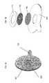
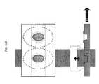
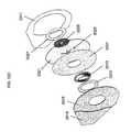
- FIGS. 1A and 1Bshow one variation of a layered adhesive holdfast in a top view and an exploded perspective view, respectively.
- FIGS. 2A-2Gare different variations of flap valves.
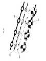
- FIGS. 3A-3Hare different variations of flap valves.
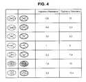
- FIG. 4Ais a table showing different variations of flap valves.
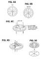
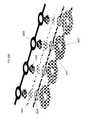
- FIGS. 5A-5Care different variations of flap valves and flap valve limiters.
- FIGS. 6A and 6B , 7 A and 7 B, 8 A- 8 G, and 9 A- 9 Care different variations of flap valves and flap valve limiters.
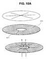
- FIG. 10A-10Eare different variations of flap valve limiters.
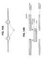
- FIG. 10Fis a graph showing the flow rate of different flap valve limiters at different back pressures.
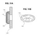
- FIG. 11Ais a side cross-sectional view of an airflow resistor, and FIG. 11B is another variation of a flap valve layer.
- FIGS. 12A-12D , 13 , 14 A and 14 B, and 15are different variations of alignment guides for an adhesive nasal device.
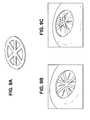
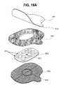
- FIGS. 16A and 16Bare rim body variations and FIGS. 16C and 16D are flap valve variations.
- FIG. 17is a matrix showing different variations of adhesive nasal devices.
- FIG. 18shows five exemplary variations of the layered nasal devices.
- FIGS. 19A and 19Bshow a layered nasal device
- FIGS. 19C-19Eshow a subject wearing the device.
- FIGS. 20A-20Gillustrate one method of fabricating the device of FIGS. 19A and 19B .
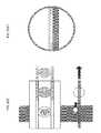
- FIGS. 21A and 21Bshow another layered nasal device.
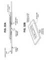
- FIGS. 22A-22Fillustrate one method of fabricating the device of FIGS. 21A and 21B .
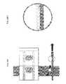
- FIGS. 23A and 23Bshow another layered nasal device.
- FIGS. 23C and 23Dare examples of the device shown in FIGS. 23A and 23B
- FIGS. 23E and 23Fshow a subject wearing the device of FIGS. 23C and 23D .
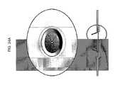
- FIGS. 24A-24Fillustrate one method of fabricating the device of FIGS. 23A and 23B .
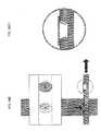
- FIGS. 25A and 25Bshow another layered nasal device.
- FIG. 25Cshows one method of assembling the adhesive nasal device shown in FIGS. 25A and 25B .
- FIGS. 26A and 26Bshow another layered nasal device.
- FIGS. 26C-26Eillustrate one method of injection molding the subassembly including the cone and flap valve.
- FIGS. 27A-27Cshow different views of a device having an injection molded flap valve.
- FIGS. 28A-28Cshows a layered nasal device.
- FIGS. 29A and 29Bshow exploded views of layered nasal devices.
- FIG. 29Cillustrates a first method of fabrication a layered nasal device.
- FIG. 29Dillustrates another method of fabricating a layered nasal device.
- FIGS. 30 and 31illustrate methods of fabricating layered nasal devices as described herein.
- FIGS. 32A-32Dshow another variation of a layered nasal device.
- FIGS. 33A and 33Bshow front and back perspective views, respectively, of one variation of an adhesive layered nasal device as described herein.
- FIG. 33Cshows an exploded perspective view of the device shown in FIGS. 33A and 33B .
- FIGS. 34A and 34Billustrate one exemplary method of using an adhesive nasal device.
- An adhesive nasal respiratory deviceis one variation of a general nasal respiratory device in which an adhesive holdfast region is used to secure the device in fluid communication with one or both of a subject's nostrils.
- a nasal respiratory deviceincluding an adhesive respiratory device, may be used to regulate a subject's respiration.
- the devicemay create positive end expiratory pressure (“PEEP”) or expiratory positive airway pressure (“EPAP”) during respiration in a subject wearing the device.
- PEEPpositive end expiratory pressure
- EPAPexpiratory positive airway pressure
- the adhesive respiratory devices and methods described hereinmay be useful to treat a variety of medical conditions, and may also be useful for non-therapeutic purposes.
- the devices and methods described hereinare not limited to the particular embodiments described. Variations of the particular embodiments described may be made and still fall within the scope of the disclosure. Examples and particular embodiments described are not intended to be limiting.
- an adhesive nasal devicemay be configured to fit across partly across, at least partly within, in, over and/or around a single nostril (e.g., a “single-nostril nasal device”), or across, in, over and/or around both nostrils (“whole-nose nasal device”).
- a single nostrile.g., a “single-nostril nasal device”
- whole-nose nasal deviceBoth single-nostril nasal devices and whole-nose nasal devices may be referred to herein as “adhesive nasal devices,” and (unless the context indicates otherwise), any of the features described for single-nostril nasal devices may be used with whole-nose nasal devices, and vice-versa.
- an adhesive nasal deviceis formed from two single-nostril nasal devices that are connected to form a unitary adhesive nasal device that can be applied to the subject's nose.
- Single-nostril nasal devicesmay be connected by a bridge (or bridge region, which may also be referred to as a connector).
- the bridgemay be movable (e.g., flexible), so that the adhesive nasal device may be adjusted to fit a variety of physiognomies.
- the bridgemay be integral to the nasal devices.
- single-nostril nasal devicesare used that are not connected by a bridge, but each include an adhesive region, so that (when worn by a user) the adhesive holdfast regions may overlap on the subject's nose.
- Layered nasal devicesare of particular interest, and are described more fully below.
- Layered adhesive nasal devicesmay include two or more layers.
- a layered nasal devicemay include an adhesive holdfast layer and an airflow resistor layer. These layers may be composed of separate layers, and these layers may be separated by other layers, or they may be adjacent.
- the adhesive holdfast layermay be itself formed of layers (optionally: a substrate layer, a protective covering layer, an adhesive layer, etc), and thus may be referred to as a layered adhesive holdfast.
- the airflow resistormay be formed of multiple layers (optionally: a flap valve layer, a valve limiter layer, etc.), and thus may be referred to as a layered airflow resistor.
- the layered adhesive holdfast and the layered airflow resistorshare one or more layers.
- the flap valves layer and the adhesive substrate layermay be the same layer, in which the leaflets of the flap valve layer are cut from the substrate layer material.
- a “layer”may be generally planar geometry (e.g., flat), although it may have a thickness, which may be uniform or non-uniform in section.
- the adhesive nasal devices described hereininclude a holdfast region (or layer) and at least one airflow resistor. As will be apparent from the figures, many of these devices may be removable and insertable by user without special tools. In some variations, a subject may use an applicator to apply the device (e.g., to help align it).
- an adhesive nasal deviceis placed in communication with one or both of a subject's nostrils to modify the flow of air through the subject's nose.
- the respiratory devices described hereininclude one or more airflow resistors for modifying the flow of air through the nose in at least one direction.
- the airflow resistoris configured to occlude airflow through a passageway in one direction more than it occludes airflow in the opposite direction.
- an airflow resistormay occlude airflow during exhalation more than inhalation. Resistance to inhalation may be increased minimally, negligibly, or not at all. Examples of airflow resistors are described below, but any appropriate airflow resistor may be used.
- airflow resistorsmay be valves for regulating airflow (e.g., flap valves, hinge-less valves, balloon valves, stepper valves, ball valves, etc.) or the like.
- the airflow resistoris typically a flap valve having one or more flaps or leaves that move to regulate flow through the resistor.
- the airflow resistormay also include a valve limiter, such as a flap valve limiter.
- a valve limiterrestricts the ability of a valve to open in one or more directions.
- the flap valve limitermay prevent the valve from substantially opening in one direction (e.g., expiration) or may allow some degree of opening or partial opening, but not complete opening
- any of the nasal devices described hereinmay also include one or more leak pathways through which air can pass when the valve is otherwise closed.
- the leak pathwaymay be separate from the airflow resistor, or it may be part of the airflow resistor (e.g., passing through a region of the flap valve, etc.).
- the airflow resistoris configured so that a leak pathway is formed when the valve is closed.
- the flap(s) of the flap valvemay not seal when the valve is closed.
- a leak pathwaymay pass through any appropriate region of the device, including the holdfast region.
- An adhesive nasal devicemay be configured to treat snoring, or any other sleep disordered breathing, as described briefly above.
- a subjectmay apply an adhesive respiratory device over his nose (one or both nostrils) by exposing an adhesive on the holdfast of the device (e.g., by removing a protective cover material from an adhesive region of the holdfast) and applying gentle pressure to adhere the device around the nostrils.
- the devicemay be seated around the nasal orifice (and may project at least partly into the nostrils) and form at least a partial seal between the nostrils and the device so that the majority of flow into and out of the nostrils passes through the passageways of the nasal device.
- the adhesive nasal deviceis configured so that there is only nominal resistance through the nasal device during inhalation (e.g., less than about 2 cm H 2 O, less than about 1 cm H 2 O less than about 0.5 cm H 2 O, less than about 0.4 cm H 2 O, less than about 0.3 cm H 2 O, less than about 0.2 cm H 2 O, etc.), but increased resistance to airflow during exhalation (e.g., greater than about 2 cm H 2 O, greater than about 3 cm H 2 O, greater than about 4 cm H 2 O, greater than about 5 cm H 2 O, greater than about 6 cm H 2 O, greater than about 7 cm H 2 O, greater than about 8 cm H 2 O, greater than about 9 cm H 2 O, greater than about 10 cm H 2 O, greater than about 12 cm H 2 O, etc.).
- nominal resistance through the nasal device during inhalatione.g., less than about 2 cm H 2 O, less than about 1 cm H 2 O less than about 0.5 cm H 2 O, less than about 0.4 cm H 2 O, less than about
- the subjectmay breathe through the nose (and thus through the nasal device).
- the adhesive nasal deviceprovides greater resistance to airflow through the device. Resistance to exhalation may be limited (or set) by a leak pathway. Thus, the subject may still breathe predominantly though the nose (and the nasal device) during exhalation, but may also breathe at least partly through the mouth.
- a nasal respiratory devicemay also be beneficial for a subject to wear a nasal respiratory device over an extended period of time (e.g., during a period of sleep).
- a nasal respiratory deviceincluding layered nasal devices
- a gripe.g., a tab, handle, strap, or other additional interface region
- This additional interface regionmay be formed of the same material as the adhesive holdfast region, or it may be a separate region, as described in more detail below.
- one or more components of the deviceare impregnated with, contain or are coated with one or more compounds that may be inhaled during use.
- the presence of airflow, heat or other conditionsmay facilitate the release of the compound into the inhaled air or surrounding tissues.
- the compoundmay be herbal (such as menthol or lavender), chemical or pharmaceutical (such as an antihistamine or anti asthma drug) in nature.
- the usermight experience a pleasant aroma (which may soothe or promote sleep or activity) or medical benefits, such as nasal decongestion or asthma relief.
- the compoundmay be inhaled during all or at least a portion of the time the user is wearing the device.
- the compoundsmay be used as part of treatment of a sleep apnea, snoring, or may find use in other embodiments for other medical conditions.
- the devicemay include a filter that removes particulate matter from external air upon inhalation. Particulate matter that would be removed may include dust and allergens.
- This inventionmay be embodied within a sleep apnea device, snoring device, a respiratory device, or comprise a stand alone device.
- Other materials of interestinclude any materials that can serve as filters for allergens, pollen, dander, smog, etc. By providing a filter within the device, sinusitis, sleep apnea, snoring, hay fever, allergic rhinitis, and other allergic respiratory conditions may be reduced or prevented.
- This filtermay in fact be part of the airflow resistor (e.g., the valve limiter) or may be a separate component of the device.
- Any suitable filtering material known to those skilled in the artmay be used with the respiratory devices described herein. Such materials include, but are not limited to, activated carbon charcoal filters, hollow-fiber filters, and the like.
- the respiratory devicemay comprise a filter that remains in the path of inhalation and/or exhalation during use.
- the filter materialremains in the path of both inspiratory and expiratory airflow. This filter material may not appreciably alter resistance to airflow in either direction, or it may alter airflow to substantially the same degree in both directions (inhalation and exhalation).
- the filtercomprises a material having a large pore size so that airflow is not significantly inhibited.
- the deviceis used with an active agent.
- the active agentcomprises a drug.
- An active agente.g., a medicament
- An active agentcan be placed in or on the device to deliver the active agent into the mouth, tongue, hard and soft palates, sinuses, nose, nasal cavity, pharynx, vocal cords, larynx, airways, lungs, trachea, bronchi, bronchioles, alveoli, air sacs, or any tissues that are exposed to inspiratory or expiratory airflow.
- the active agentmay be embedded or impregnated in the device or components of the device.
- the active agentis a coating.
- An active agentmay comprise any compound that is in some way useful or desirable for the patient.
- the active agentmay be any odorant, including: menthol, phenol, eucalyptus, or any agent that provides a fragrance in the inspired air.
- an active agentmay comprise a drug with beneficial effects, such as beneficial vasculature effects.
- an active agentmay comprise a drug that effects the blood vessels (oxymetazoline or any other vasoactive compound), nasopharynx, airways or lungs (albuterol, steroids, or other bronchoconstriction or bronchodilation compounds).
- An active agentmay comprise, for example, an antibiotic or a steroid. The above list of active agents is not meant to be limiting.
- An active agentmay be placed in or on any portion of the device. Furthermore, the location of the active agent within the respiratory device may specifically guide the delivery of the active agent. For example, in versions of the respiratory device configured to be placed inside a respiratory cavity, when the holdfast comprises an active agent (e.g., coated, embedded or otherwise part of the holdfast), the drug may be delivered through the mucus membranes of the respiratory cavity. In another example, an active agent may be included as a powder or releasable coating that may be aerosolized and delivered within the respiratory system. Thus, an active agent may be on a surface of the device (e.g., the passageway, holdfast or airflow resistor) or embedded within any surface of the device. A separate drug-containing region may also be included in the device. The addition of an active agent may be of particular interest in treating allergies and sinusitis. Respiratory devices (with or without airflow resistors) may therefore comprise active agents such as menthol or other fragrant compounds.
- active agentssuch as menthol or other fragrant compounds.
- an aligneris used to help align the device (e.g., the airflow resistor) with one or both of a subject's nostrils.
- An alignermay include a tactile aligner that may be felt by the subject's nose or hands, a visual aligner (e.g., a color, pattern, or other marking) that may be seen by the subject, or a structural aligner that inserts at least partly in or around the subject's nostril(s), or any combination of these. Aligners are described more fully below.
- an alignermay also help maintain the alignment of the device with the subject's nostril(s), for example, by helping maintain the patency of the nostril opening.
- FIG. 1Ais a top view of one example of a layered nasal device as described herein.
- the layered nasal device shown in FIG. 1includes a holdfast layer 101 and an airflow resistor 103 .
- the reverse side of the device shown in FIG. 1includes an adhesive material (not shown) that may be covered by a protective covering.
- the protective covering(which may also be referred to as a protective liner) can be removed to expose the adhesive before application of the device.
- the holdfast layer of the devicesecures it to the subject.
- This holdfast layermay itself be layered, and may include an adhesive substrate (e.g., a backing layer).
- the adhesive substratemay be a foam backing. This backing may act as a substrate for an adhesive material.
- the adhesive substrateis itself adhesive.
- the holdfast layer 101may have different regions, including a peri-nasal regions surrounding an opening (though which air may flow), and a tab 105 or grip region forming a tab that may make the device easier to grasp, apply and remove.
- Other regionsmay include regions of more aggressive and less aggressive adhesive (e.g., more or less adhesive material), regions of hydrogel material (including adhesive hydrogels) to help prevent irritation from repeated or extended use.
- the tabis shown as part of (integral with) the holdfast material, this region may also be formed separately, and may be made of different materials.
- FIG. 1Bshows an exploded view of the device of FIG. 1A .
- This exploded perspective viewillustrates the layers of the device, including the adhesive holdfast 101 (which may itself be layered), two layers of airflow resistor, including the flap valve 107 and flap valve limiter 109 , and an adhesive ring 111 that may help attach the flap valve and flap valve limiter to the adhesive holdfast.
- the holdfast, airflow resistor, alignment guide, and other device accessoriesare described in greater detail in the sections below.
- An airflow resistoris typically placed in communication with one or both of the subject's nostrils, so that at least some of the air flowing into and out of the nostrils passes through the airflow resistor.
- an adhesive nasal deviceis sealed at least partly over, at least partly within, or at least partly in or around the subject's nostril(s), and the airflow resistor may control the amount of resistance, the degree of airflow, or the pressure differential across the nasal device.
- Any appropriate airflow resistormay be used as part of the adhesive nasal devices described herein.
- the airflow resistors described hereintypically restrict airflow in one direction more than they restrict airflow in the opposite direction. For example, an airflow resistor may occlude airflow during exhalation more than inhalation. Examples of airflow resistors may be found in published U.S.
- the pressures created by the airflow resistor during exhalationmay be between 0.01 and 100 cm of H 2 O measured at a flow rate of 100 ml/sec.
- the airflow resistorcreates a resistance to exhalation that relatively low (compared to 100 cm of H 2 O).
- the resistance to exhalationmay be between about 0.5 cm of H 2 O and about 10 cm H 2 O, or between about 2 cm H 2 O and about 8 cm H 2 O, or between about 3 cm H 2 O and about 8 cm H 2 O, or about 4 cm H 2 O.
- the resistance in terms of cm of H 2 Omay be measured at a flow rate of 100 ml/sec.
- Valve-type airflow resistorsare particularly suitable.
- valves that may be usedinclude flap valves (having one or more flaps or leaflets), hingeless valves, stopper-type valves, membrane-type valves, ball valves, balloon-type valves, and the like. This list is not intended to be exhaustive, and other types of selective airflow resistors may be used.
- multiple airflow resistorsmay also be used, which may include combinations of different types of airflow resistors.
- Flap valvesare of particular interest.
- An airflow resistor configured as a flap valvetypically includes one or more hinged or flexible flaps (or leaves) that is movably secured so that the flap may open when air flows in one direction, and close when air flows in the opposite direction, or when air is not flowing.
- the opening and closing of the flapmay allow air to flow across the valve, and thereby regulate airflow within a passageway in which the flap valve is positioned.
- the flap portion of the flap valvecan thus selectively occlude airflow in one direction more than in other directions.
- Valves configured for PEEPmay also be used with any of the devices described herein.
- a valvemay be configured to have a non-zero threshold pressure for opening during expiration so that the valve is closed during expiration when the pressure across the valve is below the threshold pressure for opening during expiration, but the valve opens during expiration when the valve exceeds the threshold pressure for opening during expiration.
- an airflow resistor for use in an adhesive respiratory deviceincludes a flap valve and a flap valve limiter that limits the movement of the flap valve.
- a flap valvemay be a flexible material (e.g., silicone) that can bend or flex to create an opening for airflow during inspiration (in a first direction). The flap valve may be prevented from opening for airflow during exhalation (in a second direction) by a flap valve limiter.
- a flap valve limitermay be a structure having a flap valve engagement surface (such as a bar, post, mesh, etc.) that limits the flap valve from opening in the second direction.
- the flap valve limiteris a tether or hinge that is connected to the flap and prevents it from substantially extending beyond a predetermined position.
- Other flap valve limitersmay be configured as valve supports (e.g., cross-bars) that prevent the valve from collapsing when air flows in one direction through the passageway.
- the airflow limitermay also include a valve seal region (e.g., a rim or ridge) against which the flap may be seated or abut when the valve is “closed.”
- one or more leak pathwaysmay be included as part of the adhesive respiratory device.
- a leak pathwaytypically allows air to flow through the passageway even when the valve is closed. Thus a minimum basal level of airflow may be permitted through the passageway regardless of the state of the airflow resistor.
- the leak pathwayis a hole or unoccluded passage.
- a leak pathwaymay be a part of any region of the nasal respiratory device.
- a leak pathwaymay be part of the airflow resistor, part of the holdfast (or some combination thereof).
- the leak pathwayarises from an intentional lack of perfect sealing or abutment of various components of the device (e.g., between leaflets of a flap valve, etc).
- a nasal respiratory devicemay be configured to have multiple leak pathways.
- the flap of a flap valvemay be made of a flexible material, or a hinged stiff material.
- the flapcomprises a thin sheet of flexible material that is shaped to fit across an opening and at least partially occlude airflow through the opening when the flap is closed.
- the flapmay be shaped so that it does not occlude airflow through one or more leak pathways.
- FIG. 2A through FIG. 4show different variations of flap valves.
- the flap valve(or valves) is formed from multiple slots or openings in the valve material.
- a flap valvemay be formed from a layer of material that is cut to form different flaps or leaves.
- a flap valvemay be any appropriate shape.
- FIG. 2Ashows a flap valve having four valve leaflets (creating two valve openings) that is formed by cutting the valve layer using two H-shaped patterns.
- FIG. 2Bshows a flap valve having multiple independent leaflets that are formed by cutting the valve into seven individual flaps. Each of the leaflets has a neck region that may bend to open the flap.
- a flap valvemay be formed from an irregularly shaped cut (e.g., as shown in FIG.
- FIGS. 2D-2Gillustrate a flap valve that is formed of parallel layers.
- a side perspective viewis shown in FIG. 2D in which the flap leaflets are partially opened.
- FIG. 2Eshows a top view of this flap valve.
- FIGS. 2F and 2Gshow airflow patterns through this variation of a flap valve.
- airmay flow through the open valve, as shown. Pressure from the airflow may open the valve leaflets and keep it open.
- FIG. 2Gthe valve leaflets shown in FIG. 2F are closed, and little or no air may flow past them.
- the valve leafletsoverlap with adjacent valve leaflets in the valve layer, so that a seal may be formed when the valve is closed.
- the air flowing downwardsmay keep the valve closed.
- FIGS. 3A and 3Bthere is a space between the flap leaflets and the rest of the layer forming the flap valve 301 .
- the space between the flaps leafletsmay form a leak pathway, permitting the passage of airflow through the device.
- the flap valvesopen from a single point, as shown in FIGS. 3C and 3D .
- the flap leaflets of the flap valveare formed by cutting in a radial pattern from a single point, resulting in pie-shaped leaflets. The valve may be opened by bending back the pie-shaped wedges to form a single central opening.
- valve leaflets that open from a central pointmay be more reliably opened without interfering with the walls of the nose or nasal opening.
- flap valve shown in FIG. 3Ehas leaflets that open outwards, but from multiple points.
- the flap valves shown in FIGS. 3F and 3Gopen along a long axis of the flap valve layer, and the edges of the flap valve shown in FIG. 3H open towards a central point.
- the shape of the flap valvesmay help determine the resistance (to both expiration and inspiration) for the airflow resistor.
- the table in FIG. 4illustrates exemplary inspiratory and expiratory resistance (in cm H 2 O) of airflow resistors having a flap valve as shown in the column to the left.
- the airflow resistorincludes both the flap valve and an adjacent flap valve limiter that permits the flap valve to open in only one direction (e.g., upwards out of the page in this example, representing inspiration).
- Other factors, including the geometer of the airflow resistor, the size and location of the leak pathways, and the material from which the flap valves are mademay also affect the inspiratory and expiratory resistance.
- a flap valve(especially the flap region) may comprise any appropriate material, including those previously mentioned.
- the flapmay comprise polymeric materials, rubber (natural and synthetic), paper, fabric, or the like.
- materials which may be usedinclude: latex, polyethylene, polypropylene, polystyrene, polyvinyl chloride, polyvinylidene chloride, polyvinyl acetate, polyacrylate, styrene-butadiene copolymer, chlorinated polyethylene, polyvinylidene fluoride, ethylene-vinyl acetate copolymer, ethylene-vinyl acetate-vinyl chloride-acrylate copolymer, ethylene-vinyl acetate-acrylate copolymer, ethylene-vinyl acetate-vinyl chloride copolymer, nylon, acrylonitrile-butadiene copolymer, polyacrylonitrile, polyvinyl chloride, polychloroprene, polybutadiene, thermoplastic thermoplastic
- An airflow resistorincluding a flap valve, may be formed as a layered airflow resistor.
- a flap valve layermay be formed in any appropriate manner.
- a flap valvemay be fashioned by cutting, molding, or otherwise forming a flap valve leaflet (or a plurality of flap valve leaflets) from a layer of material.
- a layer of materiale.g., silicone, polyurethane, etc.
- Other methods of cuttingmay be used to form the valve or each valve leaflets, including laser cutting, jet cutting, or the like.
- the flap valveis formed by molding.
- the flap valvemay be formed by thermoforming, injection molding, or the like.
- the flapis made out of silicone or thermoplastic urethane.
- the flapmay be a thin and flexible piece of silicone. This flap may be any appropriate thickness that allow it to be flexible (e.g., to move from the open and closed positions).
- the flapmay comprise silicone that is between 0.0001 and 0.1 inches thick. In some embodiments, the silicone is approximately 0.002 inches thick.
- a flap valve limiteris typically an air-permeable structure that limits the range of motion of the flap valve, preventing it from opening (or limiting it to partially opening) in at least one direction.
- the flap valve limitermay be a mesh, grid, bar, peg, or other structure that does not substantially inhibit the passage of air, but can limit the movement of the flap valve leaflet(s) in at least one direction.
- FIG. 5Ashows two examples of flap valve limiters 501 that can be used with the flap valves 503 shown above them.
- the flap valve limiters 501 shownare die-cut plastic pieces having a flap valve seating surface (the surface shown) onto which the leaflets of the flap valve may rest.
- FIGS. 5B and 5Cshow similar variations of the flap valve and flap valve limiter assembly (forming an airflow resistor) incorporated in an opening through a holdfast layer.
- a flap valve limitermay be formed in any appropriate manner, including molding (e.g., injection molding), cutting (e.g., die cutting, stamping, laser cutting, etc.) or thermosetting.
- the flap valve limiteris a flap valve layer that is formed from a mesh.
- the flap valve limitermay be formed by cutting, molding, etc.
- a flap valve limitermay be formed by cutting a mesh material.
- FIGS. 6A and 6BOther examples of airflow resistors having a flap valve and a flap valve limiter are shown in FIGS. 6A and 6B during both inhalation ( FIG. 6A ) and exhalation ( FIG. 6B ). In FIG. 6A , the flap valves have opened to allow air to flow through them, while in FIG.
- FIGS. 7A and 7Bshow another airflow resistor having a leak pathway formed by the space between the valve leaflets 701 , as described briefly above.
- FIG. 7Ashows an airflow resistor having a flap valve and a flap valve resistor that is opened (e.g., during inhalation).
- FIG. 7Bshows the opposite side of the same airflow resistor during expiration.
- FIG. 8A-8Dalso illustrates this.
- the flap valve limiterlimits the movement of the flap valve by supporting the valve leaflets at their center.
- the valve leafletsmay be supported along their entire surface (e.g., when the flap valve limiter is a mesh), or at their edges.
- FIGS. 7A-8Dare configured to have four valve leaflets, any appropriate number of flaps or leaflets may be used, as mentioned above.
- FIGS. 8E and 8Fshow examples of an airflow resistor having six pie-cut valve leaflets and a flap valve limiter that may be used with it.
- FIG. 8Gshows another variation of a flap valve limiter that includes both mesh and strut regions.
- Another flap valve limiter that may be used with a six-leaf flap valveis shown in FIG. 9A
- FIGS. 9B and 9Cshow a six-leaf flap valve in operation.
- FIG. 10Ashows a mesh flap valve limiter 1010 .
- the flap valve limiter 1010includes a hole 1011 through the center region. This central hole may form a leak pathway, as shown.
- Any appropriate meshmay be used.
- the meshmay be formed of nylon or other fibrous materials.
- the valve limitermay be made of any appropriate air permeable material or shape. In some variations it may be beneficial to include materials that are flexible (e.g., nylon mesh). In some variations, it may be beneficial to use materials that are relatively stiff.
- Exemplary meshesmay include: molded polypropylene plastic mesh (e.g., 0.0140′′ thickness), precision woven nylon mesh (31.2 openings per inch ⁇ 31.2 openings per inch), precision woven nylon mesh (80 ⁇ 80), precision woven polypropylene mesh (69 ⁇ 69), filter mesh, precision woven nylon mesh (198 ⁇ 198), PTFE diamond mesh, precision woven polyester mesh (109 ⁇ 109), precision woven polyester mesh (45.7 ⁇ 45.7).
- the flap valves or the flap valve limiter(or both) is coated with a material to increase or decrease friction between the two layers (e.g., to prevent the flap leaflets from sticking to each other and/or to the flap valve limiter).
- the flap layer(forming the flap valves) is positioned immediately adjacent to a layer forming the flap valve limiter, as shown in FIG. 5A-9C , above.
- the flap valve layer and the airflow resistor layersmay not be immediately adjacent. For example, there may be an intermediate layer.
- FIGS. 10B-10Eshows flap valve limiters that are configured as struts and partial struts for limiting the motion of a flap valve layer having four leaflets.
- FIG. 10Bone variation of a layered airflow resistor is shown having four flap valve leaflets in a flap valve layer and a flap valve limiter layer in an adjacent layer that has four struts that meet in the center of the opening regulated by the flap valve, forming two complete cross bars or cross struts.
- the struts forming the flap valve limiting layersupport the flap valve approximately in the center of the each leaflet.
- the strutsare partial struts of progressively shorter length.
- FIG. 10Fback pressure at different flow rates is graphically exemplified for different flap valve limiter variations, including different partial struts.
- the flap valve limiters corresponding to each curveis indicated to the right of the graph.
- the target range indicated by the boxed region on the graphis one possible target range (e.g., during expiration when the valve is typically closed).
- the airflow resistors shown hereinhave a single flap valve layer.
- the airflow resistormay have multiple flap valve layers.
- the airflow resistormay include overlapping layers of flap valve leaflets. Multiple layers of flap valve limiters may also be used.
- Each of these layersmay be different in shape (e.g., number of leaflets, etc.). As mentioned above, the leaflets of the flap valve may also overlap when closed. Thus, a single flap valve layer may be formed of different substrate materials (e.g., silicone) that may be connected. Although the examples described above illustrate mostly layers of flap valves and flap valve limiters, the airflow resistor even an airflow resistor layer) is not necessarily formed by layers.
- FIG. 11Ashows a side cross-sectional view of an airflow resistor assembled as part of an adhesive nasal device. Additional examples are provided below.
- the flap valve layer 1101is layered immediately adjacent to the flap valve limiter 1103 .
- These componentsare secured in place between an upper 1105 and a lower 1107 substrate. They may be secured in position in any appropriate manner, including adhesive (e.g., by using the adhesive substrate region of the adhesive holdfast), by compression, by welding, by heat staking, etc.
- the flap valve layerincludes one or more attachment regions 1109 , which may be used to help secure the flap valve in position.
- the attachment regionsmay permit attachment of the layers above and below the flap valve layer (e.g., the substrate layer 1107 and the flap valve limiter 1105 , helping to lock the layer into position. This may be particularly useful when the flap valve layer is made of a material such as silicone that is otherwise difficult to bond to.
- any of the devices described hereinmay also include one or more alignment guide.
- an alignment guidemay comprise a visual alignment guide that a subject can look at to align the device (e.g., in a mirror).
- the devicemay be marked by a shape, a text, or a color to help align the device with one or both nasal openings.
- the opening to the airflow resistoris marked by a circle that can be aligned with the subject's nose.
- at least a region of the devicemay be transparent or opaque, allowing at least a portion of the nasal opening to be seen through the device.
- the alignment guideis a tactile alignment guide.
- a tactile alignment guidemay be felt by the subject (e.g., by the subject's fingers and/or nose).
- the alignment guidemay be a ring, ridge, bump, post, or the like.
- the alignment guideextends at least partially into the subject's nose when the device is worn.
- an alignment guidemay be a cone or conical region.
- FIGS. 12A to 12Dillustrate different alignment guides that may be used.
- the alignment guideis a cone or ring that at encircles the airflow resistor and can be inserted at least partly into the subject's nostril.
- the alignment guideis a ridge or rim that at least partly surrounds the airflow resistor, and is formed from the substrate (e.g., the holdfast substrate).
- FIG. 12Dshows another variation of an alignment guide in which the guide is made up of posts 1201 that project from the surface of the device.
- FIG. 13shows another variation of an airflow resistor, in which the shape of the flap valve and the flap valve limiter act as the alignment guide.
- the flap valve limiteris a rigid mesh that is indented (rather than flat), and can therefore be felt by the subject when applying the device.
- an alignment guidethat may be used is an indentation or dome that is incorporated into the flap valve limiter.
- the flap valve limiteris formed from a plastic mesh, the indentation can be heat formed during manufacture of the device.
- the flap valvesare still allowed to freely open (providing little if any resistance) in the first direction, but constrained from opening (or fully opening) in the second direction (providing resistance).
- an alignment guidemay also help protect the valve.
- an alignment guidemay prevent interference with a movable portion of the valve (e.g., flap or leaf of a flap valve) by other portions of the device or by the subject's nose, nasal hairs, “boogers,” mucous, or the like.
- a movable portion of the valvee.g., flap or leaf of a flap valve
- FIGS. 14A and 14Billustrate another tactile alignment guide included as part of the adhesive respiratory device.
- FIG. 14Ashows a cross-section through an adhesive respiratory device that has a ring around the airflow resistor region. This ring may be formed from a wire that is included during the assembly of the device, as schematically illustrate in the exploded view of FIG. 14B .
- FIG. 15shows a side perspective view of another alignment guide, similar to the conical alignment guides shown in FIGS. 12A and 12B .
- the alignment guideis somewhat flexible because of the cut-out regions shown.
- the conical alignment guidesmay be similar to the rim body region of the adhesive nasal devices described in U.S. Provisional application titled “NASAL DEVICES”, filed on Mar. 7, 2007 by Doshi et al., and previously incorporated by reference. Similar to the rim body region, the alignment guides described herein may project into the subject's nostril(s) and may help keep the nostrils open, as well as keeping the adhesive nasal device aligned with the opening.
- FIGS. 16A to 16Dillustrate one embodiment of an adhesive nasal device as described herein.
- An exploded view of this exemplary deviceis illustrated in FIG. 16A .
- This variationmay be particularly well suited to the treatment of snoring, and may be applied by a user at any time, but particularly before sleeping.
- the adhesive nasal deviceincludes an adhesive substrate (with an adhesive) 3602 , a protective cover 3601 that fits over the adhesive, an airflow resistor layer (that has multiple flap valves formed from the valve layer) 3604 , and a flap valve limiter 3608 that is at least partially made from a plastic mesh layer.
- the valve limiterincludes a thermoformed locating ring 3620 (formed or attached to the valve limiter layer).
- the device shown in FIG. 16Ais a single-nostril adhesive nasal device.
- the airflow resistor layer 3604 in this variationincludes multiple flap valves.
- this airflow resistorcomprises a silicone material that has been cut to form one or more flap valves.
- the airflow resistorcomprises a plurality of multiple flaps 3612 that are arranged in parallel or any other orientation by being cut from the same piece of silicone.
- This airflow resistor(flap layer 3604 ) is secured between the adhesive holdfast layer 3602 and the flap valve limiter 3608 .
- the adhesive layermay be made of a foam material that is adhesive on one or both sides.
- the adhesive holdfast layerWhen the adhesive holdfast layer is adhesive on both sides, it can be used to secure the airflow resistor between the adhesive holdfast layer and the flap valve limiter layer 3608 .
- the outer perimeter of the airflow resistor layer 3604is smaller than the outer perimeter of the flap valve limiter layer 3608 , but larger than the inner perimeter of the airflow resistor layer 3602 .
- the airflow resistor layercan be held by the adhesive on the adhesive holdfast 3602 against the flap valve limiter 3608 , and the adhesive holdfast layer 3602 can similarly be secured to the flap valve limiter 3608 by the adhesive. Additional attachments may also be used to secure the device components together (e.g., welds, clips, etc.).
- FIG. 16Bshows a perspective view of an assembled nasal device similar to the device shown in FIG. 16A .
- the protective cover 3601has been partially peeled back to expose the central passageway opening 3705 formed when the foam adhesive holdfast layer 3602 is combined with the flap valve limiter layer 3608 and secures the airflow resistor layer 3604 therebetween.
- the flap valves formed in the airflow resistor layer 3604 that are free to move in the opening of this passagewaymay thus open to allow air to flow through the central passageway after the air passes through the plastic mesh of the flap valve limiter layer 3608 .
- the adhesive nasal device shown in FIGS. 16A and 16Balso includes a tab or grip region 3616 , as previously described.
- the airflow resistor layer 3604may include at least one leak pathway 3614 (shown in FIG. 16A as a hole 3614 ), that permits air to pass even when the flap valves of the airflow resistor layer are held “closed” against the mesh. In some embodiments, a separate leak path may not be present.
- FIGS. 16C and 16Dillustrate airflow through the device of FIG. 16B when it is worn by a subject during inhalation and expiration, respectively.
- Both FIGS. 16C and 16Dshow a cross-section through the device of FIG. 16B taken along lines A-A′.
- the large arrows pointing upwardsrepresent airflow when the device is worn over a subject's nose. Airflow passes from the outside of the nose, though the adhesive nasal respiratory device, and into the nasal passageway during inhalation.
- the central arrowshows airflow through the leak pathway 3614
- the right and left arrowsshow airflow when the airflow resistor (parallel flap valves 3705 ) open during inhalation.
- the flap valves 3705open upwards into the passageway formed through the device 3709 , permitting air to flow through the airflow resistor as well as though the leak pathway.
- the flap valves of the airflow resistor 3705are blocked from opening in the direction of exhalation (indicated by the large arrow showing passage of air through the leak pathway) because of the mesh of the flap valve limiter layer 3608 .
- the airflow resistorsremain closed, and the only airflow through the device passes through the leak pathway, as indicated.
- the multiple flaps 3612may not completely seal on exhalation and this lack of seal may intentionally create the leak path.
- portions of the flapsmay be removed (or they may be notched for example) in order to create a desired leak path.
- the airflow resistor and/or alignment guidemay be made of any appropriate material.
- Exemplary materialsmay include: metals, plastics, rubbers, ceramics, wood, chrome, or combinations thereof.
- Other materialsmay include acrylics, latex, polyethylene, polypropylene, polystyrene, polyvinyl chloride, polyvinylidene chloride, polyvinyl acetate, polyacrylate, styrene-butadiene copolymer, chlorinated polyethylene, polyvinylidene fluoride, ethylene-vinyl acetate copolymer, ethylene-vinyl acetate-vinyl chloride-acrylate copolymer, ethylene-vinyl acetate-acrylate copolymer, ethylene-vinyl acetate-vinyl chloride copolymer, nylon, acrylonitrile-butadiene copolymer, polyacrylonitrile, polyvinyl chloride, polychloroprene, polybutadiene, thermoplastic polyimide, polyacetal, polyphenylene sulfide, polycarbonate
- Biocompatible materialsmay be used, particularly for those portions of the device which may contact a user.
- the biocompatible materialsmay also include a biocompatible polymer and/or elastomer.
- Suitable biocompatible polymersmay include materials such as: a homopolymer and copolymers of vinyl acetate (such as ethylene vinyl acetate copolymer and polyvinylchloride copolymers), a homopolymer and copolymers of acrylates (such as polypropylene, polymethylmethacrylate, polyethylmethacrylate, polymethacrylate, ethylene glycol dimethacrylate, ethylene dimethacrylate and hydroxymethyl methacrylate, and the like), polyvinylpyrrolidone, 2-pyrrolidone, polyacrylonitrile butadiene, polyamides, fluoropolymers (such as polytetrafluoroethylene and polyvinyl fluoride), a homopolymer and copolymers of st
- biocompatible and/or sterilizablemay also be preferred, for example, medical grade plastics such as Acrylonitrile Butadiene Styrene (ABS), latex, polypropylene, polycarbonate, and polyetheretherketone.
- ABSAcrylonitrile Butadiene Styrene
- latexpolypropylene
- polycarbonatepolycarbonate
- polyetheretherketonepolyetherketone
- FIG. 17is a matrix illustrating just some of the variations of the adhesive nasal devices that may be formed from the different variations of airflow resistor components.
- any flap valve geometrye.g., “s-curve”, “fish scales”, “pie slice”, etc.
- any alignment methode.g., visual aligner, tactile, etc.
- any flap valve limitere.g., mesh, full mesh, local mesh, struts, etc.
- the adhesive nasal devices described hereinmay also include an adhesive holdfast for securing the device in communication with a nasal cavity.
- the adhesive holdfastmay include one or more adhesive surfaces that are suitable for use against a subject's body (e.g., skin and/or nasal cavity).
- the adhesive holdfastmay include a biocompatible adhesive.
- the adhesive holdfastmay facilitate the positioning and securing of the device in a desired location with respect to the subject's nose, such as over, partially over, partially within, or within (e.g., substantially within) a nostril.
- An adhesive holdfastmay be configured to secure the device to any appropriate region of the subject's nose, nasal passage, or nasal cavity, including the nostrils, nares or nasal chambers, limen, vestibule, greater alar cartilage, alar fibrofatty tissue, lateral nasal cartilage, agger nasi, floor of the nasal cavity, turbinates, sinuses (frontal, ethmoid, sphenoid, and maxillary), and nasal septum.
- nasal cavitymay refer to any sub-region of the Nasal Fossa (e.g., a single nostril, nare, or nasal chamber) and includes or is defined by any of the anatomical terms listed above.
- the adhesive holdfastis configured to be applied predominantly to the outside of the nose (e.g., the skin surrounding the nasal opening or nostril).
- the holdfastmay also form a seal between the respiratory device and the nose, so that at least some of the air exchanged between the outside of the patient and the nostril must pass through the respiratory device.
- the holdfastseals the device in communication with the nose completely, so that all air through the nostril (or nostrils) must be exchanged through the device.
- the holdfast sealis incomplete, so that only some of the air exchanged between the patient and the external environment passes through the device.
- airmay be air from environment external to the patient, or it may be any respiratory gas (e.g., pure or mixed oxygen, CO 2 , heliox, or other gas mixtures provided to the user).
- the adhesive holdfastmay be flexible so that it conforms to the surface of the subject's skin, which may be relatively irregularly shaped, and may include hair and the like.
- the adhesive holdfastis made of a material that permits the passage of water vapor, liquid water, sweat and/or oil, which may enhance comfort.
- the adhesive holdfastmay also include a texture or patterned relief surface to enhance bonding to the subject's nose region.
- the adhesive holdfastmay be made of layers.
- the adhesive holdfastmay be referred to as a layered holdfast (or layered adhesive holdfast)
- the adhesive holdfastmay include a substrate layer to which a biocompatible adhesive is applied.
- the substrateis typically a flat (predominantly 2-sided) material that is flexible.
- An adhesivemay be present on at least one surface of the substrate, allowing it to adhere to the subject's nasal region.
- the substrate layeris itself adhesive without needing an additional adhesive.
- An additional protective covermay also be removably attached to the adhesive of the adhesive layer. The protective cover may allow the device (and particularly the adhesive holdfast) to be manipulated without inadvertently sticking the device to the fingers or other parts of the body and it may also prevent contamination of the adhesive.
- the linermay be a removable paper or other film that can be peeled off or otherwise removed to expose the adhesive.
- the adhesive of the adhesive holdfastis activatable. For example, the adhesive becomes ‘sticky’ only after exposure to an activator (e.g., water, air, light, etc.).
- an adhesivecould be applied to the nose in a liquid form first, than the device is applied.
- a protective coveris not used.
- the substrate and adhesiveare a single layer, so that the substrate comprises an adhesive material, or a material that can be activated to become adhesive.
- the adhesive holdfastmay comprise any appropriate material.
- the adhesive substratemay be a biocompatible material such as silicone, polyethylene, or polyethylene foam.
- Other appropriate biocompatible materialsmay include some of the materials previously described, such as biocompatible polymers and/or elastomers.
- Suitable biocompatible polymersmay include materials such as: a homopolymer and copolymers of vinyl acetate (such as ethylene vinyl acetate copolymer and polyvinylchloride copolymers), a homopolymer and copolymers of acrylates (such as polypropylene, polymethylmethacrylate, polyethylmethacrylate, polymethacrylate, ethylene glycol dimethacrylate, ethylene dimethacrylate and hydroxymethyl methacrylate, and the like), polyvinylpyrrolidone, 2-pyrrolidone, polyacrylonitrile butadiene, polyamides, fluoropolymers (such as polytetrafluoroethylene and polyvinyl fluoride), a homopolymer and copolymers of styrene acrylonitrile, cellulose acetate, a homopolymer and copolymers of acrylonitrile butadiene styrene, polymethylpentene, polysul
- the substratemay be a film, foil, woven, non-woven, foam, or tissue material (e.g., poluelofin non-woven materials, polyurethane woven materials, polyethylene foams, polyurethane foams, polyurethane film, etc.).
- tissue materiale.g., poluelofin non-woven materials, polyurethane woven materials, polyethylene foams, polyurethane foams, polyurethane film, etc.
- the adhesivemay comprise a medical grade adhesive such as a hydrocolloid or an acrylic.
- Medical grade adhesivesmay include foamed adhesives, acrylic co-polymer adhesives, porous acrylics, synthetic rubber-based adhesives, silicone adhesive formulations (e.g., silicone gel adhesive), and absorbent hydrocolloids and hydrogels.
- the adhesiveis a structural adhesive.
- the adhesivemay adhere based on van der Walls forces.
- Patents no. U.S. Pat. No. 7,011,723, U.S. Pat. No. 6,872,439, U.S. Pat. No. 6,737,160, and U.S. Pat. No. 7,175,723describe setal-like structures whose shape and dimension provide adhesive force. These patents are herein incorporated by reference in their entirety.
- the removable liner layermay be made of any appropriate matter that may be released from the adhesive.
- the liner materialmay comprise craft paper.
- the liner materialcomprises polyethylene film, or polyethylene coated paper (e.g. kraft paper).
- the linermay be any of the other materials described herein.
- an adhesive layermay be formed in any appropriate method, particularly those described herein.
- an adhesive layermay be formed by cutting (stamping, die cutting, laser cutting, etc.) the adhesive substrate, biocompatible adhesive, and protective cover into the desired shape. Multiple steps may be used to form the adhesive layer.
- the adhesive layermay be formed by cutting (or otherwise forming) the outer perimeter, then by cutting (or otherwise forming) an inner opening.
- the adhesive holdfastmay comprise any appropriate shape that allows the airflow resistor to be positioned with respect to one or both nasal passages so that some (or most) of the airflow through the nasal passages must pass through the adhesive nasal device.
- the adhesive holdfastattaches to the nose (or nasal passage) and forms a partial or complete seal therewith, thereby channeling airflow into or out of the nasal passageway through the device, and also securing the device in position.
- the entire adhesive holdfast regionincludes an adhesive, although many of the substantially flat holdfast regions described in the preceding figures may have a biocompatible adhesive over much of the skin-contacting surface (although it may be covered by a protective cover that can be at least partially removed later).
- the region adjacent to the rim bodymay not include an adhesive, or the region beneath the tabs or grips may not include an adhesive.
- the adhesive nasal devices described hereinare adapted to fit different users having a diversity of sizes and shapes, particularly the shapes and sizes of their noses.
- the devicesincluding particularly the adhesive holdfast region, may be configured to that it is adaptable to different nose shapes.
- the holdfast regionmay extend into the nostril, rather than just adhering around the outer surface of the nasal passages.
- the adhesive holdfastmay include a region that projects into the nostril, and can be secured against the walls of the nostril.
- the internally-projecting regionsmay comprise a compressible material (e.g., a foam or the like) so that they may be secured within the nasal passages, and/or may cushion the inner rim base region (or any other portion of the adhesive nasal device) that projects into the subject's nostrils.
- a compressible materiale.g., a foam or the like
- the inwardly-projecting portion of the holdfastis smaller than the nasal opening, and does not necessarily contact the sides of the subject's nasal passage.
- FIG. 18shows five exemplary variations of the layered nasal devices described herein. Each of these variations is described briefly below with accompanying drawings.
- FIGS. 19A and 19Bshow one variation of a layered nasal device having an airflow resistor including a flap valve limiter that is made of a flexible mesh.
- This flap valve limitermay be referred to as a local flexible mesh valve limiter because this mesh layer is trimmed, and is not coextensive with the adhesive of the adhesive holdfast region (e.g., it is underlies just the flap valve layer). This may be seen in the cross-section shown in FIG. 19A , and in the circular detail region shown in FIG. 19B .
- the left side of FIG. 19Bshows a bottom view of this variation of an adhesive nasal device.
- the adhesive nasal devicemay be formed by sequentially layering onto a backing layer that protects one side of double-sided adhesive (forming the adhesive holdfast), cutting out (e.g., die-cutting) an opening through this adhesive holdfast substrate, applying the flap valve layer (which may be any of the flap valves described above, but is shown here as a silicone S-cut flap valve) so that the flap valve spans the opening, applying the pre-trimmed mesh (over the flap valve spanning the opening, and securing another (single-sided) adhesive layer having a corresponding opening over the sandwiched flap valve and mesh.
- the flap valve layerwhich may be any of the flap valves described above, but is shown here as a silicone S-cut flap valve
- FIGS. 19A and 19BThe adhesive nasal device shown in FIGS. 19A and 19B is shown being worn by a subject in FIGS. 19C to 19E .
- FIGS. 20A-20Gillustrate one method of manufacturing multiple adhesive nasal devices as shown in FIGS. 19A and 19B .
- FIGS. 21A and 21Bshow another variation of a layered nasal device having an airflow resistor including a flap valve limiter that is made of a flexible mesh.
- This flap valve limitermay be referred to as a full flexible mesh because the mesh forming this limiter layer is not trimmed, and extends further than the opening through the adhesive holdfast region. This may be seen in the cross-section shown in FIG. 21A , and in the circular detail region shown in FIG. 21B .
- the left side of FIG. 21Bshows a top view of a partially constructed adhesive nasal device.
- This devicemay be formed by sequentially layering a backing layer protecting one side of double-sided adhesive (forming the adhesive holdfast), cutting out (e.g., via die-cutting) an opening through this substrate, applying a flap valve layer (e.g., any of the valves described above, shown here as a fish-scale flap valve) spanning this opening, and applying the un-trimmed mesh over the flap valve layer to sandwiched the flap valve with the mesh.
- a flap valve layere.g., any of the valves described above, shown here as a fish-scale flap valve
- FIGS. 22A-22Fillustrate one method of manufacturing multiple adhesive nasal devices as shown in FIGS. 19A and 19B .
- FIGS. 23A and 23Bshow another variation of a layered nasal device having an airflow resistor including a flap valve limiter that is made of a mesh and includes an alignment guide shown here as a cone. This may be seen in the cross-section shown in FIG. 23A , and in the detail region shown in FIG. 23B .
- the left side of FIG. 23Bshows a top view of a partially constructed adhesive nasal device.
- this devicemay be formed by sequentially layering a backing layer protecting one side of double-sided adhesive (forming the adhesive holdfast), cutting out (e.g., via die-cutting) an opening through this substrate, inserting the alignment guide cone into the opening, applying a flap valve layer (e.g., any of the valves described above, shown here as a silicone six pie-cut flap valve) spanning this opening, applying the pre-trimmed mesh over the flap valve spanning the opening, and securing another (single-sided) adhesive layer having a corresponding opening over the sandwiched flap valve and mesh.
- a flap valve layere.g., any of the valves described above, shown here as a silicone six pie-cut flap valve
- FIGS. 23A and 23BThe adhesive nasal device shown in FIGS. 23A and 23B is illustrated in FIGS. 23C and 23D , and is shown worn by a subject in FIGS. 23E and 23F .
- FIGS. 24A-24Fillustrate one method of manufacturing multiple adhesive nasal devices as shown in FIGS. 23A and 23B .
- FIGS. 25A and 25Bshow another variation of a layered nasal device having an airflow resistor including a flap valve limiter that is a pre-molded mesh formed by injection molding and includes a conical alignment guide. This may be seen in the cross-section shown in FIG. 25A , and in the detail in the circled region shown in FIG. 25B .
- the left side of FIG. 25Bshows a top view of a partially formed adhesive nasal device.
- This variation of the adhesive nasal devicemay be formed by sequentially layering onto a backing layer protecting one side of double-sided adhesive (forming the adhesive holdfast), inserting the pre-molded alignment guide cone into the opening, applying a flap valve layer (e.g., any of the valves described above, shown here as a silicone six pie-cut flap valve), inserting the pre-molded mesh, and securing another (single-sided) adhesive layer having a corresponding opening to secure the mesh, valve and cone into position.
- a flap valve layere.g., any of the valves described above, shown here as a silicone six pie-cut flap valve
- FIG. 25COne possible method of assembling the adhesive nasal device shown in FIGS. 25A and 25B is illustrated in FIG. 25C .
- a method of manufacturing the cone (application guide), flap valve and flap valve limiter (mesh) by ultrasonic weldingis described.
- a welding horn and welding fixtureare used to ultrasonically weld these three components together to form a subassembly, as shown.
- This subassemblymay then be inserted into the opening formed in the adhesive substrate (adhesive holdfast).
- FIGS. 26A and 26Bshow another variation of a layered nasal device having an airflow resistor including a flap valve that is a pre-molded (e.g., formed by injection molding) and includes a conical alignment guide. This may be seen in the cross-section shown in FIG. 26A , and in the detail in the circled region shown in FIG. 26B .
- the left side of FIG. 26Bshows a top view of an adhesive nasal device.
- This variation of the adhesive nasal devicemay be formed by cutting an opening into a backing layer that protects one side of double-sided adhesive (forming the adhesive holdfast), inserting the pre-molded flap valve and cone subassembly into the opening, applying the flap valve limiter (mesh) over the flap valve, and securing another (single-sided) adhesive layer having a corresponding opening around the airflow resistor to secure the mesh, valve and cone in position.
- FIGS. 26C-26Dillustrate one method of injection molding the subassembly including the cone and flap valve.
- the coneis first injection molded (in FIG. 26C ), and then the flap valve layer is injection molded (or LIM molded) within the cone to a thickness of approximately 0.003′′ (in FIG. 26D ).
- the flap valve leafletsare die cut from the molded flap valve layer (in FIG. 26E ).
- FIGS. 27A-27Calso show different views of a device having an injection molded flap valve.
- FIG. 28Aincludes an exploded view of an adhesive nasal device in which the airflow resistor is includes a stiff (e.g., die cut or injection molded) plastic piece that secure the flap valve and acts as the flap valve limiter.
- This airflow resistor subassemblycan be secured within a cut-out region of an adhesive holdfast to form the adhesive nasal device.
- FIGS. 28B and 28Cshow bottom and top views, respectively, of this variation.
- the stiff subassemblymay also act to prop open the nasal passages, as well as acting as an alignment guide.
- FIGS. 29A and 29Bshow exploded views of layered nasal devices having slightly different arrangements of the layers.
- an additional adhesive layeris present between the flap valve limiter and the flap valve, compared with the adhesive nasal device shown in FIG. 29A .
- FIGS. 29C and 29Dillustrate possible methods of fabricating exemplary layered nasal devices.
- the devices described hereinmay be batch fabricated, or fabricated by hand.
- the layered devices described hereinmay be fabricated by sequentially layering various to form the final device.
- a layermaybe pre-processed by cutting, trimming, etc., or otherwise modifying it.
- Batch processingmay be performed by layering strips or sheets corresponding to the different layers, and cutting or stamping the devices out of the strips or sheets after they have been at least partially assembled.
- FIGS. 29C and 29Dschematically illustrate one method of fabricating devices from layered strips. For example, in FIG. 29C , the layers forming the device may be sequentially added after each layer has been formed.
- the adhesive holdfast layer 2907(comprising an adhesive substrate and an adhesive) may be formed by, for example, cutting a continuous strip of annular shapes that are initially connected 2911 , as shown.
- the layered airflow resistormay then be formed by cutting the flap valve leaflets from a flap valve substrate (e.g., a silicone layer) to form a flap valve layer 2901 that is also a continuous strip of connected flap valves, and placing the flap valve layer adjacent to a flap valve liming layer 2903 .
- This layered airflow resistormay then be attached to the adhesive holdfast layer by an adhesive ring 2905 . Once the layers have been assembled, the individual flap valves may be separated by cutting or otherwise removing the connecting region 2911 . A similar process is illustrated in FIG.
- FIG. 29Dexcept the devices fabricated also include an aligner, shown here as a conical aligner 2909 .
- the order of the layers in FIG. 29Dis different than the arrangement shown in FIG. 29C .
- the skin-contacting surface of the adhesive holdfastis visible (facing “up” out of the page) and the flap valve limiter is between the flap valve layer and the adhesive substrate.
- the skin-contacting surface of the adhesive holdfastis not visible (facing “down,” out of the page) and the flap valve layer is between the flap valve limiter layer and the adhesive holdfast layer.
- a nasal adhesive devicemay be fabricated by forming each layer (e.g., but cutting the adhesive holdfast substrate, the flap leaflets, etc.), and by placing the positing the flap valve limiter adjacent to the flap valve layer and adhesively securing the layers (using, for example, an adhesive ring).
- the flap valve leafletsmay be formed of the adhesive substrate layer.
- a continuous fabrication processmay include layering the device as part of a rolling strip of materials that are sequentially layered, as shown in FIG. 30 . In FIG. 30 ( 1 ), openings are punched or cut form the adhesive holdfast layer that consists of a double-sided tape substrate and a removable backing layer.
- step ( 2 )a strip of flap valve material is applied, and the flap valve material is cut (e.g., die cut) to form the flap leaflets in step ( 3 ).
- the mesh (flap valve limiter) layeris applied in step ( 4 ) so that the mesh is aligned with the openings and the flap valves.
- An additional adhesive layeris applied in step ( 5 ) to seal the airflow resistor within the opening of the adhesive holdfast, and the individual adhesive nasal devices may be cut from the strip, as shown in step ( 6 ).
- FIG. 31shows a similar fabrication method. Other batch fabrication methods were illustrated previously for some of the variations described above, for example in FIGS. 20A-20G , FIGS. 22A-22E , and FIGS. 24A-24F .
- FIGS. 32A-32Dshow another variation of a layered nasal device.
- This deviceis a multi-layered layered device.
- the device shownhas three layers: an adhesive (adhesive holdfast) layer, an air permeable barrier (the valve limiting layer), and the elastomeric valve layer. These layers are shown in FIG. 32A .
- FIGS. 32A and 32Bshow the arrangement of these layers to form the adhesive nasal device.
- the adhesive layerforms a substrate onto which the airflow resistor layers (the air permeable barrier and the elastomer) are secured.
- an opening through the adhesive holdfastis covered with an air permeable layer, such as a mesh.
- this layermay be secured to the adhesive layer by any appropriate method (including using the adhesive of the adhesive layer, or an additional adhesive).
- Two parallel strips of elastomeric materialare placed adjacent to the air permeable layer spanning the opening, and secured at the ends (and possibly along one side).
- a gap(forming the leak pathway) may be left between the two strips, as shown in FIG. 32D .
- multiple stripsmay be used to form the valve (e.g., see FIG. 2E-2G ).
- This adhesive nasal devicemay be placed in communication with a subject's nostril(s) so that when the subject inhales, the elastomeric bands forming the valve flex away from the air-permeable layer (the valve limiting layer), and open to allow air to flow with only minimal resistance. This is illustrated in FIG. 32B .
- the strips of elastomeric material forming the valveare limited from flexing by the valve limiting layer formed from the air-permeable barrier, resulting in a resistance to expiration, as air is only allowed to pass through the leak pathway between the strips forming the valve layer.
- the device shown in FIGS. 32A-32Dmay be used to treat medical conditions including snoring, and typically can be worn by a subject to provide a small resistance to expiration (e.g., between about 2 and about 20 cm H 2 O, between about 2 and about 8 cm H 2 O, between about 2 and about 6 cm H 2 O, or about 4 cm H 2 O).
- a small resistance to expiratione.g., between about 2 and about 20 cm H 2 O, between about 2 and about 8 cm H 2 O, between about 2 and about 6 cm H 2 O, or about 4 cm H 2 O.
- FIGS. 33A and 33Billustrate another example of a layered nasal device.
- FIG. 33Ashows a front view of the device.
- the deviceincludes an adhesive holdfast region that includes a tab or handle 3311 portion.
- the adhesive holdfastis a layer that surrounds an airflow resistor region that (in this example) includes a flap valve and a flap valve limiter.
- the flap valve limiteris visible in FIG. 33A as layer 3305 , as is a portion of the adhesive substrate 3307 .
- the adhesive substrateis formed from a thin film of material
- the airflow resistoris a flap valve that is formed in the adhesive substrate layer, as will be more readily apparent in the exploded view of FIG. 33C .
- the thin film of materiale.g., silicone, polyurethane, or other thin film material
- the device in FIG. 33Aalso includes a support frame 3309 .
- the support frame 3309may help support the thin film of the adhesive substrate, preventing it from folding or wrinkling (or otherwise losing its shape) in an undesirable manner.
- the support framemay be adhesively attached to the adhesive substrate, and may be removed (similar to the protective coating region described above) from the device once it is positioned over the subject's nasal cavity. Removing the support frame may allow the device to conform (and perhaps seal) over a subject's nasal cavity.
- a support framemay extend across a portion of one side of the device (typically the side that does not contact the skin). In general, the support frame may extend to support at least three sides of the adhesive holdfast region, to maintain the general shape of the adhesive holdfast region.
- the support framecovers the entire surface of the device (the side that does not contact the skin when the device is worn by a subject).
- a support framemay be made of any appropriate material, including the materials described above for the protective cover.
- the support framemay also be considered a layer, as shown in FIGS. 33A and 33C .
- the support framemay also include a handle or tab region to help facilitate removal of the support frame from device (e.g., by peeling it off) when the device is approximately positioned.
- FIG. 33Bshows the opposite side of the device shown in FIG. 33A .
- This side of the devicemay be referred to as the skin contacting side, since it typically includes the adhesive side of the adhesive holdfast, which is not visible beneath the protective cover 3315 , 3315 ′ in FIG. 33B .
- This protective cover 3315 , 3315 ′has two regions that may be separately removed.
- the first region of the protective cover 3315covers the adhesive holdfast around the airflow resistor, including the alignment guide 3313 .
- a second protective cover 3315 ′covers the tab (or grip) region 3311 .
- the first protective covermay be removed to position and initially attach the device to the subject (e.g., in communication with the subject's nasal cavity).
- the second protective cover 3315 ′can then be removed to further attach the tab region.
- the support frame layercan then be removed from the opposite (outward facing) side to allow the device to completely adhere to the skin, as described above.
- FIG. 33Cshows an exploded view of the device shown in FIGS. 33A and 33B .
- the central layeris the thin film adhesive substrate layer 3321 .
- This layeris also the flap valve layer, and the central flap valve leaflets 3323 have been cut into the layer.
- a flap valve limiter layer 3325is positioned adjacent to the flap valves, and secured in place with a ring of adhesive 3327 .
- the support frame 3311can be secured (e.g., via an adhesive) to the thin film of the adhesive substrate layer.
- a layer of adhesive 3331may be applied or otherwise secured to the opposite side of the thin film adhesive substrate.
- both sides of the adhesive substrateare adhesive (or include an adhesive layer), or the thin film adhesive substrate is itself adhesive.
- An alignment guide 3313may then be attached around the airflow resistor and secured to the layered adhesive holdfast by a ring of adhesive 3337 (e.g., a two-sided adhesive ring).
- any of the layered adhesive devices described hereinmay be used to treat snoring or other sleep disordered breathing.
- a subjectmay apply the device to his or her own nose.
- the devicesmay be first removed from clean or sterile packaging.
- the devices described hereinmay be sized (e.g., child/adult, small, medium, large, etc.), or one-size-fits-all. Placement of an adhesive nasal device may be done in front of a mirror or can occur without looking at a mirror.
- a device having an adhesive holdfast with a protective covermay be prepared for application by first removing the protective cover, and then aligning the airflow resistor (or alignment guide) with one or both nostrils (depending on the device).
- the devicemay then be applied to the nostril (e.g., over the nostril) by pushing the adhesive holdfast against the nostril to secure the airflow resistor in communication with the nostril(s).
- the usermay test whether an adequate seal has been created or has been maintained between the adhesive holdfast and the region in, on, over or around the nostrils through a variety of methods. On exhalation for example, it will be clear to the user whether a good seal has been created between the device and his nasal cavity because exhalation will be more difficult.
- the devicemay be removed by peeling the adhesive holdfast away from the nostril.
- An adhesive nasal deviceis typically worn over each nostril so that the airflow resistor allows airflow through the nostrils to be substantially unaffected by inspiration, but provides resistance to expiratory airflow through the nose. However, it may be advantageous to reverse this arrangement to inhibit inspiratory airflow and allow expiratory airflow to occur through the nose without substantial resistance.
- an airflow resistormay be worn on only one nostril so that there is a resistance to airflow during expiration in only one nostril and there is no significant resistance to inspiration or exhalation through the other nostril.
- a device having a fixed resistancecould be worn by over, around or in one nostril, while the other nostril is in communication with an airflow resistor configured to have little inspiratory resistance and significant expiratory resistance.
- the device(s)may be worn or configured so that there is a greater resistance to airflow during inspiration in one nostril, and a greater resistance to airflow during exhalation in the other nostril. In general, however, it is believed that providing a slight resistance to airflow during expiration in both nostrils may be used to treat snoring or other sleep disordered breathing.
- FIGS. 34A and 34Billustrate how an adhesive single-nostril nasal device such as those described above.
- a usermay first peel off all (or a part of) the protective cover, exposing the adhesive holdfast region. The user may then place the device over one of the nostrils, so that the passageway through the device is aligned with the nasal openings.
- An alignment guidemay help the user to align the nasal opening and the central passageway of the device.
- the locating ringmay have a texture, color, or shape that the user can feel, helping to position the device correctly.
- the alignment guidemay be a locating ring that is a thermoformed ring.
- the adhesive devicemay be applied against the nostril to secure it into position. The user may first wash the area to which the adhesive device will be applied to remove material (e.g., dirt, oils, etc.) that could prevent adhesion (and/or a seal) between the adhesive device and the nostril and/or nose.
- a second devicemay be applied to the other nostril.
- the adhesive holdfast regions of the two devicesmay overlap.
- the usermay simply peel off the adhesive devices.
- itwill facilitate removal of the second device since the two once-independent devices may be adhered together.
Landscapes
- Health & Medical Sciences (AREA)
- General Health & Medical Sciences (AREA)
- Pulmonology (AREA)
- Engineering & Computer Science (AREA)
- Biomedical Technology (AREA)
- Public Health (AREA)
- Heart & Thoracic Surgery (AREA)
- Hematology (AREA)
- Life Sciences & Earth Sciences (AREA)
- Animal Behavior & Ethology (AREA)
- Veterinary Medicine (AREA)
- Anesthesiology (AREA)
- Emergency Medicine (AREA)
- Otolaryngology (AREA)
- Business, Economics & Management (AREA)
- Emergency Management (AREA)
- Bioinformatics & Cheminformatics (AREA)
- Orthopedics, Nursing, And Contraception (AREA)
- Respiratory Apparatuses And Protective Means (AREA)
- Medicinal Preparation (AREA)
Abstract
Description
Claims (40)
Priority Applications (5)
| Application Number | Priority Date | Filing Date | Title |
|---|---|---|---|
| US11/759,916US8985116B2 (en) | 2006-06-07 | 2007-06-07 | Layered nasal devices |
| TW096146792ATWI474847B (en) | 2006-06-07 | 2007-12-07 | Layered nasal devices |
| US12/141,875US8061357B2 (en) | 2004-12-08 | 2008-06-18 | Adhesive nasal respiratory devices |
| US13/035,524US20110203598A1 (en) | 2006-06-07 | 2011-02-25 | Nasal devices including layered nasal devices and delayed resistance adapters for use with nasal devices |
| US13/299,181US8302607B2 (en) | 2004-12-08 | 2011-11-17 | Adhesive nasal respiratory devices |
Applications Claiming Priority (4)
| Application Number | Priority Date | Filing Date | Title |
|---|---|---|---|
| US81181406P | 2006-06-07 | 2006-06-07 | |
| US85971506P | 2006-11-16 | 2006-11-16 | |
| US90585007P | 2007-03-07 | 2007-03-07 | |
| US11/759,916US8985116B2 (en) | 2006-06-07 | 2007-06-07 | Layered nasal devices |
Related Parent Applications (1)
| Application Number | Title | Priority Date | Filing Date |
|---|---|---|---|
| US12/329,895Continuation-In-PartUS20090145441A1 (en) | 2006-06-07 | 2008-12-08 | Delayed resistance nasal devices and methods of use |
Related Child Applications (3)
| Application Number | Title | Priority Date | Filing Date |
|---|---|---|---|
| US11/298,339Continuation-In-PartUS7798148B2 (en) | 2004-12-08 | 2005-12-08 | Respiratory devices |
| US12/141,875Continuation-In-PartUS8061357B2 (en) | 2004-12-08 | 2008-06-18 | Adhesive nasal respiratory devices |
| US13/035,524Continuation-In-PartUS20110203598A1 (en) | 2006-06-07 | 2011-02-25 | Nasal devices including layered nasal devices and delayed resistance adapters for use with nasal devices |
Publications (2)
| Publication Number | Publication Date |
|---|---|
| US20070283962A1 US20070283962A1 (en) | 2007-12-13 |
| US8985116B2true US8985116B2 (en) | 2015-03-24 |
Family
ID=38832411
Family Applications (4)
| Application Number | Title | Priority Date | Filing Date |
|---|---|---|---|
| US11/811,339ActiveUS7506649B2 (en) | 2006-06-07 | 2007-06-07 | Nasal devices |
| US11/759,916Expired - Fee RelatedUS8985116B2 (en) | 2004-12-08 | 2007-06-07 | Layered nasal devices |
| US12/369,681Expired - Fee RelatedUS7987852B2 (en) | 2006-06-07 | 2009-02-11 | Nasal devices |
| US13/164,684AbandonedUS20110240038A1 (en) | 2006-06-07 | 2011-06-20 | Nasal devices |
Family Applications Before (1)
| Application Number | Title | Priority Date | Filing Date |
|---|---|---|---|
| US11/811,339ActiveUS7506649B2 (en) | 2006-06-07 | 2007-06-07 | Nasal devices |
Family Applications After (2)
| Application Number | Title | Priority Date | Filing Date |
|---|---|---|---|
| US12/369,681Expired - Fee RelatedUS7987852B2 (en) | 2006-06-07 | 2009-02-11 | Nasal devices |
| US13/164,684AbandonedUS20110240038A1 (en) | 2006-06-07 | 2011-06-20 | Nasal devices |
Country Status (8)
| Country | Link |
|---|---|
| US (4) | US7506649B2 (en) |
| EP (2) | EP2032213A4 (en) |
| JP (2) | JP5261378B2 (en) |
| KR (1) | KR101447903B1 (en) |
| AU (1) | AU2007258524B2 (en) |
| CA (1) | CA2658966A1 (en) |
| IL (1) | IL195700A (en) |
| WO (2) | WO2007146207A2 (en) |
Cited By (8)
| Publication number | Priority date | Publication date | Assignee | Title |
|---|---|---|---|---|
| US9833354B2 (en) | 2004-12-08 | 2017-12-05 | Theravent, Inc. | Nasal respiratory devices |
| USD874064S1 (en) | 2018-05-18 | 2020-01-28 | Trudell Medical International | Mask |
| USD893806S1 (en) | 2018-11-09 | 2020-08-18 | Trudell Medical Internationl | Mask and shroud |
| USD903097S1 (en) | 2018-05-18 | 2020-11-24 | Trudell Medical International | Mask |
| WO2021150985A1 (en) | 2020-01-22 | 2021-07-29 | Seelos Therapeutics, Inc. | Reducing side effects of nmda antagonists |
| US11439869B2 (en) | 2017-05-19 | 2022-09-13 | Trudell Medical International | Positive expiratory pressure device |
| WO2022241214A1 (en) | 2021-05-14 | 2022-11-17 | Seelos Therapeutics, Inc. | Methods of using nmda receptor antagonists |
| US12440457B2 (en) | 2023-04-11 | 2025-10-14 | Seelos Therapeutics, Inc. | Methods of treating suicidality |
Families Citing this family (144)
| Publication number | Priority date | Publication date | Assignee | Title |
|---|---|---|---|---|
| US6722360B2 (en) | 2000-06-16 | 2004-04-20 | Rajiv Doshi | Methods and devices for improving breathing in patients with pulmonary disease |
| EP1824544B1 (en) | 2004-12-08 | 2013-06-05 | Ventus Medical, Inc. | Respiratory devices and methods of use |
| US8061357B2 (en)* | 2004-12-08 | 2011-11-22 | Ventus Medical, Inc. | Adhesive nasal respiratory devices |
| US10610228B2 (en) | 2004-12-08 | 2020-04-07 | Theravent, Inc. | Passive nasal peep devices |
| US7644714B2 (en)* | 2005-05-27 | 2010-01-12 | Apnex Medical, Inc. | Devices and methods for treating sleep disorders |
| GB0610171D0 (en) | 2006-05-23 | 2006-06-28 | Robitaille Jean Pierre | Valved nasal canula |
| CA2653139C (en)* | 2006-05-23 | 2016-01-05 | Ventus Medical, Inc. | Nasal respiratory devices |
| US20090145441A1 (en)* | 2007-12-06 | 2009-06-11 | Rajiv Doshi | Delayed resistance nasal devices and methods of use |
| CN101489630B (en)* | 2006-06-07 | 2013-10-23 | 温吐斯医学公司 | Layered nasal devices |
| US20110203598A1 (en)* | 2006-06-07 | 2011-08-25 | Favet Michael L | Nasal devices including layered nasal devices and delayed resistance adapters for use with nasal devices |
| EP2032213A4 (en) | 2006-06-07 | 2014-02-19 | Theravent Inc | DEVICES FOR THE NOSE |
| US20110180076A1 (en)* | 2006-06-19 | 2011-07-28 | Kasey K. LI | Wearable tissue retention device |
| US8347890B2 (en)* | 2006-06-19 | 2013-01-08 | Insono Therapeutics, Inc. | Automated tissue retention system |
| US8613283B2 (en) | 2006-06-19 | 2013-12-24 | Insono Therapeutics, Inc. | Mandibular advancement appliance |
| US8857439B2 (en)* | 2006-06-19 | 2014-10-14 | Insono Therapeutics, Inc. | Variable automated tissue retention system |
| US9205262B2 (en) | 2011-05-12 | 2015-12-08 | Cyberonics, Inc. | Devices and methods for sleep apnea treatment |
| US8855771B2 (en) | 2011-01-28 | 2014-10-07 | Cyberonics, Inc. | Screening devices and methods for obstructive sleep apnea therapy |
| CA2666529A1 (en) | 2006-10-13 | 2008-04-24 | Apnex Medical, Inc. | Obstructive sleep apnea treatment devices, systems and methods |
| US9744354B2 (en) | 2008-12-31 | 2017-08-29 | Cyberonics, Inc. | Obstructive sleep apnea treatment devices, systems and methods |
| US9186511B2 (en) | 2006-10-13 | 2015-11-17 | Cyberonics, Inc. | Obstructive sleep apnea treatment devices, systems and methods |
| US9913982B2 (en) | 2011-01-28 | 2018-03-13 | Cyberonics, Inc. | Obstructive sleep apnea treatment devices, systems and methods |
| WO2008061252A2 (en) | 2006-11-16 | 2008-05-22 | Ventus Medical, Inc. | Nasal devices applicators |
| TW200836781A (en)* | 2007-03-07 | 2008-09-16 | Ventus Medical Inc | Nasal devices |
| US20080247214A1 (en)* | 2007-04-03 | 2008-10-09 | Klaus Ufert | Integrated memory |
| AU2008202850A1 (en)* | 2007-06-29 | 2009-01-15 | Bird Healthcare Pty Ltd | Inhalation device |
| CN101854975A (en) | 2007-10-03 | 2010-10-06 | 桑诺斯泰克公司 | Nasal inserts |
| EP2481438B1 (en) | 2007-11-19 | 2015-09-23 | Koninklijke Philips N.V. | A patient interface device including a coating adhesive layer |
| US8020700B2 (en) | 2007-12-05 | 2011-09-20 | Ventus Medical, Inc. | Packaging and dispensing nasal devices |
| WO2009099995A1 (en)* | 2008-02-01 | 2009-08-13 | Ventus Medical, Inc. | Cpap interface and backup devices |
| AU2009221772B2 (en) | 2008-03-05 | 2015-01-22 | Solventum Intellectual Properties Company | Dressing and method for applying reduced pressure to and collecting and storing fluid from a tissue site |
| US8291906B2 (en) | 2008-06-04 | 2012-10-23 | Resmed Limited | Patient interface systems |
| US20110100369A1 (en)* | 2008-06-15 | 2011-05-05 | Liang Zhang | Nasal Device for Obesity Prevention and Treatment |
| US20090308398A1 (en)* | 2008-06-16 | 2009-12-17 | Arthur Ferdinand | Adjustable resistance nasal devices |
| JP5702723B2 (en) | 2008-09-04 | 2015-04-15 | ザ ジェネラル ホスピタル コーポレイション | Hydrogels for strengthening and repairing vocal cords and soft tissues |
| US20110218451A1 (en)* | 2008-09-15 | 2011-09-08 | Danny Yu-Youh Lai | Nasal devices, systems and methods |
| US20110232636A1 (en)* | 2008-12-18 | 2011-09-29 | Koninklijke Philips Electronics, N.V. | Valved holding chamber and mask therefor |
| US20100163048A1 (en)* | 2008-12-29 | 2010-07-01 | Owel Siordia | Nose filters |
| WO2010076704A1 (en) | 2008-12-30 | 2010-07-08 | Koninklijke Philips Electronics N.V. | System and respiration appliance for supporting the airway of a subject |
| JP5723785B2 (en) | 2008-12-30 | 2015-05-27 | コーニンクレッカ フィリップス エヌ ヴェ | System, method and respiratory device for supporting a subject's airway |
| US8646453B2 (en)* | 2009-03-20 | 2014-02-11 | Kasey Kai-Chi Li | Extendable airflow restriction system |
| US20100241159A1 (en)* | 2009-03-20 | 2010-09-23 | Li Kasey K | Airflow restriction system |
| US8607797B2 (en)* | 2009-03-20 | 2013-12-17 | Kasey K. LI | Airflow restriction system |
| US20110108041A1 (en)* | 2009-11-06 | 2011-05-12 | Elliot Sather | Nasal devices having a safe failure mode and remotely activatable |
| EP3957348B1 (en) | 2010-01-05 | 2024-03-06 | Yeda Research and Development Co. Ltd | Odor device for preventing snoring or apnea events |
| IT1398484B1 (en)* | 2010-02-24 | 2013-03-01 | Mistro | NASAL ANATOMIC DILATOR. |
| US8177689B2 (en)* | 2010-03-01 | 2012-05-15 | Bas Rutten | Oxygen trainer device |
| US9198568B2 (en) | 2010-03-04 | 2015-12-01 | The General Hospital Corporation | Methods and systems of matching voice deficits with a tunable mucosal implant to restore and enhance individualized human sound and voice production |
| US9901487B2 (en)* | 2010-03-10 | 2018-02-27 | C. Howard Steinberg | Anus crevice insert |
| US9339626B2 (en)* | 2010-03-16 | 2016-05-17 | Carefusion 207, Inc. | Seal for variable compression interfaces |
| US8814842B2 (en) | 2010-03-16 | 2014-08-26 | Kci Licensing, Inc. | Delivery-and-fluid-storage bridges for use with reduced-pressure systems |
| EP2572170A1 (en) | 2010-05-17 | 2013-03-27 | Mindray Medical Sweden AB | Coaxial means for measuring a flow and a method of measuring a flow |
| SE535494C2 (en)* | 2010-05-17 | 2012-08-28 | Mindray Medical Sweden Ab | Coaxial flowmeter element and method for measuring flow |
| US8393228B2 (en) | 2010-05-18 | 2013-03-12 | Mindray Medical Sweden Ab | Method and system for measuring a flow |
| US8276618B2 (en) | 2010-05-18 | 2012-10-02 | Mindray Medical Sweden Ab | Flow restrictor and method for reducing resistance of a flow |
| US8875711B2 (en) | 2010-05-27 | 2014-11-04 | Theravent, Inc. | Layered nasal respiratory devices |
| USD652518S1 (en)* | 2010-06-18 | 2012-01-17 | Eva Jensen | Nasal respirator |
| US20120006329A1 (en)* | 2010-07-06 | 2012-01-12 | Beevers Katherine K | Method of partially adhering cpap mask to face |
| US20120125327A1 (en)* | 2010-10-18 | 2012-05-24 | Patricia Blair Huntington | Nasal Passage Strip |
| USD671620S1 (en)* | 2010-11-22 | 2012-11-27 | Hollister Incorporated | Valve with tactile position indication |
| US9084859B2 (en) | 2011-03-14 | 2015-07-21 | Sleepnea Llc | Energy-harvesting respiratory method and device |
| US10603456B2 (en) | 2011-04-15 | 2020-03-31 | Fisher & Paykel Healthcare Limited | Interface comprising a nasal sealing portion |
| WO2012151095A1 (en)* | 2011-05-04 | 2012-11-08 | First Defense Holdings Llc | Nasal filter structure |
| US8844533B2 (en) | 2011-06-22 | 2014-09-30 | Breathe Technologies, Inc. | Ventilation mask with integrated piloted exhalation valve |
| US9038634B2 (en) | 2011-06-22 | 2015-05-26 | Breathe Technologies, Inc. | Ventilation mask with integrated piloted exhalation valve |
| US9616194B2 (en) | 2011-06-22 | 2017-04-11 | Breathe Technologies, Inc. | Ventilation mask with integrated piloted exhalation valve and method of ventilating a patient using the same |
| US9730830B2 (en) | 2011-09-29 | 2017-08-15 | Trudell Medical International | Nasal insert and cannula and methods for the use thereof |
| US10463529B2 (en)* | 2012-11-05 | 2019-11-05 | Jennifer Sparr | Device and method for deterring back-lying snoring posture |
| US10905842B2 (en) | 2011-11-21 | 2021-02-02 | Snap Cpap, Llc | Respiratory assembly |
| US11207484B2 (en) | 2011-11-21 | 2021-12-28 | Snap Cpap, Llc | Respiratory assembly |
| US10265493B2 (en) | 2011-11-21 | 2019-04-23 | Snap Cpap, Llc | Respiratory assembly |
| US9149595B2 (en) | 2011-11-21 | 2015-10-06 | Stuart Heatherington | Respiratory mask assembly |
| US10940047B2 (en) | 2011-12-16 | 2021-03-09 | Kci Licensing, Inc. | Sealing systems and methods employing a hybrid switchable drape |
| CN103987348B (en) | 2011-12-16 | 2016-05-11 | 凯希特许有限公司 | Releasable Medical Drapes |
| US10238827B2 (en)* | 2012-03-12 | 2019-03-26 | Mark T. Holtzapple | Air-delivery system for breathing-assist devices |
| JP6292600B2 (en)* | 2012-10-09 | 2018-03-14 | 学校法人慶應義塾 | Respiratory device |
| EP2908770B1 (en) | 2012-10-16 | 2019-04-24 | Cook Medical Technologies LLC | Apparatus for treating obstructive sleep apnea (osa) |
| AU2013344686B2 (en) | 2012-11-16 | 2018-06-21 | Solventum Intellectual Properties Company | Medical drape with pattern adhesive layers and method of manufacturing same |
| US9795756B2 (en) | 2012-12-04 | 2017-10-24 | Mallinckrodt Hospital Products IP Limited | Cannula for minimizing dilution of dosing during nitric oxide delivery |
| SMT201700286T1 (en) | 2012-12-04 | 2017-07-18 | Ino Therapeutics Llc | Cannula for minimizing dilution of dosing during nitric oxide delivery |
| EP2964166B1 (en)* | 2013-03-06 | 2018-11-28 | Black, Jed, Eric | Adhesive devices for improving breathing and/or sleep using such devices |
| ITRM20130132A1 (en)* | 2013-03-06 | 2014-09-07 | Hsd Holding Smart Device S R L | INHALER ELEMENT OF MEDICAMENTOUS SUBSTANCES. |
| US11648370B2 (en)* | 2013-03-06 | 2023-05-16 | Jed Eric Black | Devices and methods for encouraging nasal breathing |
| US20160030229A1 (en)* | 2013-03-13 | 2016-02-04 | Ge Sleeping Technologies Ltd. | Method and system for breathing modulation |
| AU2014306232B2 (en) | 2013-08-05 | 2018-12-06 | C2Dx, Inc. | Medical devices having a releasable tubular member and methods of using the same |
| CA2919449C (en) | 2013-08-05 | 2022-04-12 | Fisher & Paykel Healthcare Limited | Seal for a patient interface, interface assemblies and aspects thereof |
| US10946124B2 (en) | 2013-10-28 | 2021-03-16 | Kci Licensing, Inc. | Hybrid sealing tape |
| AU2014342903B2 (en) | 2013-10-30 | 2018-09-20 | Solventum Intellectual Properties Company | Dressing with differentially sized perforations |
| US9956120B2 (en) | 2013-10-30 | 2018-05-01 | Kci Licensing, Inc. | Dressing with sealing and retention interface |
| EP3527237B1 (en) | 2013-10-30 | 2020-09-09 | KCI Licensing, Inc. | Absorbent conduit and system |
| EP3062751B1 (en) | 2013-10-30 | 2017-08-09 | KCI Licensing, Inc. | Condensate absorbing and dissipating system |
| US20150216709A1 (en)* | 2014-01-31 | 2015-08-06 | Joe Peck | Nasal Dilator |
| US20150216711A1 (en)* | 2014-01-31 | 2015-08-06 | Joe Peck | Protective Adhesive Safety Strips |
| EP3104768B1 (en) | 2014-02-11 | 2023-07-26 | Cyberonics, Inc. | Systems for detecting and treating obstructive sleep apnea |
| US10569037B2 (en) | 2014-02-14 | 2020-02-25 | John M. O'Day | Nasopharyngeal device for obstructive sleep apnea syndrome |
| US11026844B2 (en) | 2014-03-03 | 2021-06-08 | Kci Licensing, Inc. | Low profile flexible pressure transmission conduit |
| US9974563B2 (en) | 2014-05-28 | 2018-05-22 | Cook Medical Technologies Llc | Medical devices having a releasable member and methods of using the same |
| JP6640748B2 (en) | 2014-06-05 | 2020-02-05 | ケーシーアイ ライセンシング インコーポレイテッド | Dressing with fluid acquisition and dispensing features |
| CN106413788B (en) | 2014-06-17 | 2019-12-20 | 费雪派克医疗保健有限公司 | Patient interface |
| WO2016022454A1 (en) | 2014-08-04 | 2016-02-11 | Darin Schaeffer | Medical devices having a releasable tubular member and methods of using the same |
| US10646679B2 (en) | 2014-09-05 | 2020-05-12 | Bryggs Medical Llc | Respiratory apparatus and method for treating sleep apnea |
| US10086161B1 (en) | 2014-09-05 | 2018-10-02 | Briggs Medical, Llc | Respiratory apparatus and method for treating sleep apnea |
| CN104307120A (en)* | 2014-10-27 | 2015-01-28 | 安徽省科普产品工程研究中心有限责任公司 | Dust-proof nose plug and method for testing dust-proof effect of dust-proof nose plug |
| DE102014016608B3 (en)* | 2014-11-10 | 2016-04-07 | Ndd Medizintechnik Ag | Breathing tube for use in ultrasonic flow measuring systems |
| US20160135980A1 (en)* | 2014-11-14 | 2016-05-19 | Derrick D. Earls | SINU Pads |
| WO2016100098A1 (en) | 2014-12-17 | 2016-06-23 | Kci Licensing, Inc. | Dressing with offloading capability |
| US20160243323A1 (en)* | 2015-02-24 | 2016-08-25 | Kevin W. Burns | Barrier Device |
| US10195088B2 (en) | 2015-04-13 | 2019-02-05 | Emergency Medical Innovation LLC | Nasal compression device |
| EP3574877B1 (en) | 2015-05-08 | 2022-08-17 | 3M Innovative Properties Company | Low-acuity dressing with integral pump |
| KR20180016419A (en)* | 2015-06-05 | 2018-02-14 | 에이에스에이피 브리드어시씨스트 피티와이 엘티디 | Nose extension |
| US20170016648A1 (en)* | 2015-07-14 | 2017-01-19 | Rommy Zohair Ahmed | Nasal strip face warmer |
| EP3741335B1 (en) | 2015-09-01 | 2023-05-24 | KCI Licensing, Inc. | Dressing with increased apposition force |
| US10994090B2 (en) | 2015-09-04 | 2021-05-04 | Fisher & Paykel Healthcare Limited | Patient interfaces |
| US10525227B1 (en) | 2015-09-10 | 2020-01-07 | Stock IP Holdings LLC | Nasal EPAP dilator |
| EP3349807B1 (en) | 2015-09-17 | 2021-02-24 | 3M Innovative Properties Company | Hybrid silicone and acrylic adhesive cover for use with wound treatment |
| US11511066B2 (en) | 2015-10-06 | 2022-11-29 | Snap Cpap, Llc | Respiratory assembly |
| JP6771571B2 (en)* | 2016-02-04 | 2020-10-21 | アトス メディカル アクティエボラーグ | Tracheal fistula device holder |
| KR200482172Y1 (en) | 2016-03-15 | 2016-12-30 | 김형준 | a fender package |
| WO2017165583A1 (en)* | 2016-03-23 | 2017-09-28 | Sanostec Corp | Nasal insert having one or more sensors |
| US10576241B2 (en) | 2016-05-04 | 2020-03-03 | George Volgyesi | Breath powered positive airway pressure device |
| US10828459B2 (en) | 2016-05-04 | 2020-11-10 | George Volgyesi | Breath powered positive airway pressure device |
| JP7187450B2 (en) | 2016-10-05 | 2022-12-12 | フィッシャー アンド ペイケル ヘルスケア リミテッド | patient interface |
| US20200188709A1 (en)* | 2016-11-14 | 2020-06-18 | Nanoclean Global Pvt. Ltd. | Nanofiber based nasal filter and a process of preparation thereof |
| US20180221618A1 (en)* | 2017-02-03 | 2018-08-09 | Lunatussin, LLC | Inhalation Therapy Device |
| WO2018165372A1 (en) | 2017-03-08 | 2018-09-13 | Ohio State Innovation Foundation | Nasal plug |
| CN107308565A (en)* | 2017-07-01 | 2017-11-03 | 高级全球创新有限公司 | A kind of Novel filtration mouth mask |
| KR101904138B1 (en)* | 2017-07-26 | 2018-10-04 | 유한책임회사 샤워트리 | Mask of nostrils inserting filter type |
| WO2019046728A1 (en)* | 2017-09-02 | 2019-03-07 | Snap Cpap, Llc | Respiratory assembly |
| JP2019180567A (en)* | 2018-04-04 | 2019-10-24 | 株式会社パタカラ | Nasal cavity insertion tool |
| USD884153S1 (en) | 2018-04-04 | 2020-05-12 | Fisher & Paykel Healthcare Limited | Frame for a mask assembly |
| KR20190127668A (en)* | 2018-05-02 | 2019-11-13 | 이노스파크스 피티이 엘티디 | Multi-Flap Valves for Breathing Devices |
| USD932015S1 (en) | 2018-05-08 | 2021-09-28 | Resprana, Inc. | Nasal filter |
| US10335311B1 (en)* | 2018-05-31 | 2019-07-02 | Barry I. Altman | Anti-snoring device |
| RU2710608C1 (en)* | 2018-09-27 | 2019-12-30 | Денис Александрович Горбатюк | Inhalation device |
| US11571537B2 (en) | 2019-03-28 | 2023-02-07 | Koninklijke Philips N.V. | Adhesive alignment system for patient interfaces |
| US11484677B2 (en) | 2019-03-28 | 2022-11-01 | Koninklijke Philips N.V. | Adhesive patient interface assembly with removal tabs |
| KR102064174B1 (en)* | 2019-04-24 | 2020-01-08 | 백수정 | Dust Removing Plate for Body-Adhesion |
| CN110403746B (en)* | 2019-07-08 | 2024-09-24 | 中山大学孙逸仙纪念医院 | Bladder fistulization tube |
| CN114449983A (en)* | 2019-09-30 | 2022-05-06 | 皇家飞利浦有限公司 | Variable skin breathable adhesive placement for patient interface |
| WO2021168285A1 (en) | 2020-02-21 | 2021-08-26 | Ohio State Innovation Foundation | Vented nasal plug |
| KR102208982B1 (en)* | 2020-04-14 | 2021-01-29 | 주식회사 위리코 | Breathable sheet with a single or multi-layered structure for blocking foreign substances and improving breathability, mask and manufacturing method using the same, food container using the same, and window type air filter using the same |
| US11154102B1 (en) | 2020-04-24 | 2021-10-26 | David J. Ahearn | Self-adhesive nasal mask |
| WO2021244891A1 (en) | 2020-06-04 | 2021-12-09 | Koninklijke Philips N.V. | Tuneable expiratory positive airway pressure (tepap) apparatus and method |
| US12064559B2 (en)* | 2020-06-08 | 2024-08-20 | Koninklijke Philips N.V. | Sealing arrangement for forming a seal between a patient and a patient interface device |
| CN216294938U (en)* | 2021-07-29 | 2022-04-15 | 方卓元 | Automatic pressure boost respirator |
Citations (286)
| Publication number | Priority date | Publication date | Assignee | Title |
|---|---|---|---|---|
| US69396A (en) | 1867-10-01 | Robert brayton and samuel curtis | ||
| US628111A (en) | 1899-03-11 | 1899-07-04 | Samuel M Mchatton | Nose-screen. |
| US669098A (en) | 1900-05-26 | 1901-03-05 | Timothy Taylor Overshiner | Inhaler. |
| US675275A (en) | 1900-05-25 | 1901-05-28 | Josephus H Gunning | Nasal device. |
| US718785A (en) | 1902-09-16 | 1903-01-20 | James Welch Mcnary | Respirator. |
| US746869A (en) | 1903-08-05 | 1903-12-15 | Stillman Augustus Moulton | Device for preventing snoring. |
| US774446A (en) | 1904-05-19 | 1904-11-08 | Stillman Augustus Moulton | Device for preventing snoring. |
| US810617A (en) | 1905-01-03 | 1906-01-23 | Thomas Carence | Nasal shield. |
| US1819884A (en) | 1930-04-14 | 1931-08-18 | Fores Fernando | Nostril insert |
| US2198959A (en) | 1939-06-07 | 1940-04-30 | Hubert E Clarke | Nasal filter |
| US2237954A (en) | 1939-06-30 | 1941-04-08 | William R Wilson | Nasal filter and inhaler |
| US2264153A (en) | 1940-02-19 | 1941-11-25 | Madeleine Pope | Nasal appliance |
| US2274886A (en) | 1940-08-10 | 1942-03-03 | Harold D Carroll | Nasal respirator |
| US2282681A (en) | 1939-08-14 | 1942-05-12 | Cha Gobe Company | Nasal filter |
| US2335936A (en) | 1940-09-30 | 1943-12-07 | Joseph T Hanlon | Nasal dilating device |
| US2433565A (en) | 1946-06-21 | 1947-12-30 | Korman Alexander | Nose filter |
| US2448724A (en) | 1946-04-02 | 1948-09-07 | Clarence L Mcgovney | Nasal filter |
| US2593315A (en) | 1946-10-31 | 1952-04-15 | Dole Valve Co | Flow control device |
| US2672138A (en) | 1950-09-05 | 1954-03-16 | Carlock Marion Pomeroy | Device to promote nasal breathing and prevent snoring |
| US2751906A (en) | 1953-10-26 | 1956-06-26 | Mary E Irvine | Nose filters |
| US2777442A (en) | 1955-04-11 | 1957-01-15 | Zelano Joseph | Nasal filter |
| US3145711A (en) | 1961-12-08 | 1964-08-25 | Beber Arthur | Disposable nasal filter |
| US3315701A (en) | 1962-08-13 | 1967-04-25 | Fmc Corp | Flow timing device |
| US3370305A (en) | 1965-05-28 | 1968-02-27 | Goott Bernard | Heart valve with magnetic hinge means |
| US3451392A (en) | 1966-02-24 | 1969-06-24 | Irving L Cook | Nose filter |
| US3463149A (en) | 1968-07-05 | 1969-08-26 | Theodor Albu | Nose air filter |
| US3513839A (en) | 1968-01-02 | 1970-05-26 | Matthew Vacante | Valved nose filter |
| US3556122A (en) | 1964-06-15 | 1971-01-19 | Laerdal A S | Valve for artificial respiration apparatus |
| US3616802A (en)* | 1969-08-20 | 1971-11-02 | Frank A Marinaccio | Filtering device |
| US3657855A (en) | 1969-08-25 | 1972-04-25 | Union Camp Corp | Process and apparatus for forming display packages |
| US3695265A (en) | 1970-10-26 | 1972-10-03 | Elmer Lawrence Brevik | Face mask |
| US3710799A (en) | 1969-06-30 | 1973-01-16 | C Caballero | Nose dilator |
| US3722509A (en) | 1971-01-05 | 1973-03-27 | J Nebel | Nasal filters |
| US3747597A (en) | 1971-11-03 | 1973-07-24 | V Olivera | Nasal filter |
| US3802426A (en) | 1972-09-08 | 1974-04-09 | M Sakamoto | Nasal filter |
| US3884223A (en) | 1974-06-26 | 1975-05-20 | Lawrence Peska Ass Inc | Nasal filter |
| US3902621A (en) | 1974-08-05 | 1975-09-02 | Walter E Hidding | Tamperproof closure with grippable handle |
| US4004584A (en) | 1975-07-28 | 1977-01-25 | Alleraid Company, Inc. | Facially-worn breathing filter |
| US4030491A (en) | 1975-10-31 | 1977-06-21 | Alvin Mattila | Nasal filter |
| US4040428A (en) | 1976-08-30 | 1977-08-09 | The Aro Corporation | Control valves for tracheotomy patient or laryngeal prosthesis |
| US4054134A (en) | 1975-09-15 | 1977-10-18 | Kritzer Richard W | Respirators |
| JPS52123786A (en) | 1976-04-07 | 1977-10-18 | Mitsubishi Plastics Ind Ltd | Method of packaging skin |
| US4062358A (en) | 1976-04-21 | 1977-12-13 | Kritzer Richard W | Respirators |
| US4094316A (en) | 1976-08-26 | 1978-06-13 | Eric Nathanson | Adhesive bandage with reusable applique |
| US4143872A (en) | 1977-04-07 | 1979-03-13 | Hudson Oxygen Therapy Sales Company | Lung volume exerciser |
| US4212296A (en) | 1978-04-20 | 1980-07-15 | The Kendall Company | Bandage with protective member |
| JPS55122742U (en) | 1979-02-24 | 1980-09-01 | ||
| US4220150A (en) | 1978-09-13 | 1980-09-02 | King John R | Nasal dust filter |
| US4221217A (en) | 1978-05-01 | 1980-09-09 | Amezcua Saul O | Nasal device |
| US4226233A (en) | 1978-10-10 | 1980-10-07 | Longevity Products, Inc. | Respirators |
| US4240420A (en) | 1979-04-16 | 1980-12-23 | Florence Riaboy | Nose and mouth filter combination |
| US4267831A (en) | 1979-09-24 | 1981-05-19 | Aguilar Rogelio M | Nasal air filter and medicament dispenser device |
| US4327719A (en) | 1980-12-15 | 1982-05-04 | Childers Irene J | Nose filter |
| USRE31040E (en) | 1975-04-24 | 1982-09-28 | St. Jude Medical, Inc. | Heart valve prosthesis |
| US4354489A (en) | 1979-04-16 | 1982-10-19 | Florence Riaboy | Individual nose and mouth filters |
| GB2096574A (en) | 1981-04-10 | 1982-10-20 | Fraser Chemicals Nottingham Lt | Package assemblies |
| JPS58136345A (en) | 1982-02-05 | 1983-08-13 | 与那原 好宏 | Breathing sound arrestor |
| US4403616A (en) | 1981-06-09 | 1983-09-13 | K-Med, Inc. | Expiratory breathing exercise device |
| US4456016A (en) | 1982-07-01 | 1984-06-26 | Trutek Research, Inc. | Inhalation valve |
| US4487207A (en) | 1981-10-15 | 1984-12-11 | Edward Fitz | Lung exercising device and method |
| US4533137A (en) | 1982-01-19 | 1985-08-06 | Healthscan Inc. | Pulmonary training method |
| US4582058A (en) | 1984-11-26 | 1986-04-15 | Bivona, Inc. | Tracheostoma valves |
| US4584997A (en) | 1984-02-27 | 1986-04-29 | Delong Harold D | Volumetric flow gauge |
| US4601465A (en) | 1984-03-22 | 1986-07-22 | Roy Jean Yves | Device for stimulating the human respiratory system |
| US4640277A (en) | 1984-05-17 | 1987-02-03 | Texas College Of Osteopathic Medicine | Self-contained breathing apparatus |
| US4651873A (en) | 1985-11-04 | 1987-03-24 | Stolcenberg Dennis A | Can caddy device, and methods of constructing and utilizing same |
| US4702374A (en) | 1986-04-21 | 1987-10-27 | Robert Kelner | Package assembly with testing feature for illuminated product |
| US4718554A (en) | 1986-10-21 | 1988-01-12 | Pakula And Company | Method of carding pierced earrings and assembly thereby formed |
| US4739987A (en) | 1985-10-28 | 1988-04-26 | Nicholson Marguerite K | Respiratory exerciser |
| JPS63189257U (en) | 1987-05-29 | 1988-12-05 | ||
| US4822354A (en) | 1986-09-02 | 1989-04-18 | Elosegui Ignacio M | Mechanical valvular prothesis for use in cardiac surgery |
| US4854574A (en) | 1988-03-15 | 1989-08-08 | 501 Healthscan, Inc. | Inspirator muscle trainer |
| US4860766A (en) | 1983-11-18 | 1989-08-29 | Respitrace Corp. | Noninvasive method for measuring and monitoring intrapleural pressure in newborns |
| US4862903A (en) | 1987-10-09 | 1989-09-05 | U.S. Divers Company, Inc. | Breathing mouthpiece for contacting upper palate and lower jaw of user's mouth |
| US4908028A (en) | 1987-03-20 | 1990-03-13 | Jean Colon | Valve incorporating at least one rocking flap with respect to elastic pivots |
| US4913138A (en) | 1987-11-07 | 1990-04-03 | Haruo Yoshida | Adhesive bandage for personal use |
| US4919138A (en) | 1987-11-13 | 1990-04-24 | Nordenstrooem Bjoern | Method and apparatus for supplying electric energy to biological tissue for simulating the physiological healing process |
| SU1586709A1 (en) | 1988-07-05 | 1990-08-23 | Киевский Политехнический Институт Им.50-Летия Великой Октябрьской Социалистической Революции | Apparatus for normalizing the functions of breathing system |
| WO1990012614A1 (en) | 1989-04-25 | 1990-11-01 | Lincoln Robert A | Nose-worn air filter |
| US4973047A (en) | 1988-12-09 | 1990-11-27 | Erik Norell | Therapeutic device for lung exercise |
| US4979505A (en) | 1989-06-06 | 1990-12-25 | Cox Everard F | Tracheal tube |
| US4984302A (en) | 1987-03-20 | 1991-01-15 | Robert A Lincoln | Nose-worn air filter |
| US4984581A (en) | 1988-10-12 | 1991-01-15 | Flexmedics Corporation | Flexible guide having two-way shape memory alloy |
| US5016425A (en) | 1988-07-13 | 1991-05-21 | Weick Heinz Hermann | Dispenser for the vaporization of active substances to be inhaled |
| EP0434258A2 (en) | 1989-12-21 | 1991-06-26 | Smiths Industries Public Limited Company | Adhesive dressing assemblies and methods of dressing |
| US5033312A (en) | 1989-11-06 | 1991-07-23 | Bicore Monitoring Systems | Gas flow meter housing |
| US5038621A (en) | 1989-11-06 | 1991-08-13 | Bicore Monitoring Systems | Variable area obstruction gas flow meter |
| US5052400A (en) | 1986-02-20 | 1991-10-01 | Dietz Henry G | Method and apparatus for using an inhalation sensor for monitoring and for inhalation therapy |
| US5059208A (en) | 1991-02-04 | 1991-10-22 | Helix Medical, Inc. | Adjustable tracheostoma valve |
| US5074293A (en) | 1988-11-30 | 1991-12-24 | Sherwood Medical Company | Wound dressing having peeling-force varying release liners |
| US5078739A (en) | 1990-07-20 | 1992-01-07 | Janus Biomedical, Inc. | Bileaflet heart valve with external leaflets |
| US5092781A (en) | 1990-11-08 | 1992-03-03 | Amp Incorporated | Electrical connector using shape memory alloy coil springs |
| US5117820A (en) | 1989-11-16 | 1992-06-02 | Robitaille Jean Pierre | Intra-nasal filter |
| JPH0540589A (en) | 1991-08-02 | 1993-02-19 | Canon Inc | Multi-window display method and device |
| US5197980A (en) | 1990-08-14 | 1993-03-30 | Gorshkov Jury V | Cardiac valve prosthesis |
| WO1993008777A1 (en) | 1991-11-06 | 1993-05-13 | Bioderm, Inc. | Occlusive wound dressing and applicator |
| US5255687A (en) | 1992-01-21 | 1993-10-26 | Mckenna Charles L | Zero dead space respiratory exercise valve |
| US5383470A (en) | 1993-09-20 | 1995-01-24 | Steve Novak | Portable spirometer |
| US5385542A (en) | 1991-02-12 | 1995-01-31 | Smith & Nephew Plc | Tampon applicators |
| US5391205A (en) | 1991-12-17 | 1995-02-21 | Knight; Roy F. | Tracheoesophageal voice prosthesis |
| US5392773A (en) | 1994-04-13 | 1995-02-28 | Bertrand; Archie A. | Respiratory particulate filter |
| US5394867A (en) | 1991-06-05 | 1995-03-07 | Brookdale International Systems Inc. | Personal disposable emergency breathing system with dual air supply |
| US5414627A (en) | 1992-08-17 | 1995-05-09 | Mitsubishi Denki Kabushiki Kaisha | Electric power steering control device for automotive vehicle |
| US5415660A (en) | 1994-01-07 | 1995-05-16 | Regents Of The University Of Minnesota | Implantable limb lengthening nail driven by a shape memory alloy |
| JPH0747126B2 (en) | 1987-04-22 | 1995-05-24 | 三菱重工業株式会社 | Exhaust gas treatment catalyst |
| US5425359A (en) | 1994-08-29 | 1995-06-20 | Liou; Nan-Tien | Nose plug structure with filter |
| WO1995017220A1 (en) | 1993-12-21 | 1995-06-29 | Maersk Medical A/S | A device for the supply of oxygen and/or other gases to a patient |
| US5459544A (en) | 1993-02-01 | 1995-10-17 | Konica Corporation | Camera with a shape memory alloy member |
| RU2048820C1 (en) | 1991-03-12 | 1995-11-27 | Владимир Андреевич Старцев | Device for saturating air with medicinal substances |
| WO1995033520A1 (en) | 1994-06-02 | 1995-12-14 | Noreen Hurlin | Filtration device |
| US5522382A (en) | 1987-06-26 | 1996-06-04 | Rescare Limited | Device and method for treating obstructed breathing having a delay/ramp feature |
| US5535739A (en) | 1992-05-07 | 1996-07-16 | New York University | Method and apparatus for optimizing the continuous positive airway pressure for treating obstructive sleep apnea |
| US5562641A (en) | 1993-05-28 | 1996-10-08 | A Bromberg & Co. Ltd. | Two way shape memory alloy medical stent |
| US5568808A (en) | 1995-08-08 | 1996-10-29 | Amtec Products, Incorporated | Nose filters |
| US5572994A (en) | 1995-06-07 | 1996-11-12 | Smith; Steven W. | Occlusion resistant oxygen supply conduit for a nasal cannula |
| US5607469A (en) | 1993-10-28 | 1997-03-04 | Inocor Gmbh | Bi-leaflet prosthetic heart valve |
| US5649533A (en) | 1993-06-07 | 1997-07-22 | Oren; Nathan | Therapeutic respiration device |
| US5665104A (en) | 1996-08-20 | 1997-09-09 | Lee; Chi Hao Edwin | Breathing enhancer |
| US5727546A (en)* | 1993-08-18 | 1998-03-17 | Fisons Plc | Powder inhaler with breath flow regulation valve |
| US5730122A (en) | 1996-11-12 | 1998-03-24 | Cprx, Inc. | Heart failure mask and methods for increasing negative intrathoracic pressures |
| US5740798A (en) | 1994-04-22 | 1998-04-21 | Mckinney; Stella H. | Disposable nasal band filter |
| US5743256A (en) | 1996-03-07 | 1998-04-28 | Jalowayski; Alfredo A. | Nostril closure means |
| US5763979A (en) | 1996-02-29 | 1998-06-09 | The United States Of America As Represented By The Secretary Of The Navy | Actuation system for the control of multiple shape memory alloy elements |
| US5775335A (en) | 1997-05-29 | 1998-07-07 | Seal; Daniel J. | Apparatus to diminish or eliminate snoring |
| US5782896A (en) | 1997-01-29 | 1998-07-21 | Light Sciences Limited Partnership | Use of a shape memory alloy to modify the disposition of a device within an implantable medical probe |
| US5797920A (en) | 1996-06-14 | 1998-08-25 | Beth Israel Deaconess Medical Center | Catheter apparatus and method using a shape-memory alloy cuff for creating a bypass graft in-vivo |
| US5803121A (en) | 1997-04-17 | 1998-09-08 | Chrysler Corporation | Air bag venting system |
| US5823187A (en) | 1991-11-01 | 1998-10-20 | Estes; Mark C. | Sleep apnea treatment apparatus with a therapy delay circuit arrangement |
| WO1998046310A2 (en) | 1997-04-15 | 1998-10-22 | Jury Vasilievich Khalezov | Method and device for the protection of the human respiratory or gans |
| GB2324729A (en) | 1997-04-30 | 1998-11-04 | Bradford Hospitals Nhs Trust | Lung treatment device |
| US5848590A (en) | 1995-07-25 | 1998-12-15 | Kapitex Healthcare Limited | Tracheostoma filter with HME properties |
| WO1999003395A1 (en) | 1997-07-18 | 1999-01-28 | Optovent Aktiebolag (Publ) | Method and device to sense breathing |
| US5865170A (en) | 1997-07-23 | 1999-02-02 | Moles; Randall C. | Customizable mouthpiece for scuba-divers |
| US5876434A (en) | 1997-07-13 | 1999-03-02 | Litana Ltd. | Implantable medical devices of shape memory alloy |
| US5890998A (en) | 1995-02-10 | 1999-04-06 | Hougen; Everett Douglas | Portable personal breathing apparatus |
| US5899832A (en) | 1996-06-14 | 1999-05-04 | Hougen; Everett D. | Compact lung exercising device |
| US5910071A (en) | 1995-02-10 | 1999-06-08 | Hougen; Everett D. | Portable, personal breathing apparatus |
| US5911756A (en) | 1996-06-26 | 1999-06-15 | Novatech | Intralaryngeal prosthesis |
| JP3059270U (en) | 1998-08-14 | 1999-07-09 | 淳 後藤 | Snoring nose plug with ventilation valve |
| US5947119A (en) | 1997-10-31 | 1999-09-07 | Reznick; Jerald M. | Therapeutic process and apparatus for nasal passages |
| US5954766A (en) | 1997-09-16 | 1999-09-21 | Zadno-Azizi; Gholam-Reza | Body fluid flow control device |
| US5957978A (en) | 1997-12-22 | 1999-09-28 | Hansa Medical Products, Inc. | Valved fenestrated tracheotomy tube |
| US5992006A (en) | 1998-12-23 | 1999-11-30 | Fonar Corporation | Method for passive control of magnet hemogeneity |
| US6004342A (en) | 1998-03-26 | 1999-12-21 | Filis; Elias A. | Nasal insert device for improving breathing |
| US6058932A (en) | 1997-04-21 | 2000-05-09 | Hughes; Arthur R. | Acoustic transceiver respiratory therapy apparatus |
| WO2000029066A1 (en) | 1998-11-17 | 2000-05-25 | Martin Johan Brinckman | Disposable nose filter |
| US6083141A (en) | 1995-02-10 | 2000-07-04 | Hougen; Everett D. | Portable respiratory exercise apparatus and method for using the same |
| WO2000050121A1 (en) | 1999-02-25 | 2000-08-31 | Respironics, Inc. | Adhesive nasal mask assembly, system and method of using same |
| USD430667S (en) | 1998-10-15 | 2000-09-05 | Harold Rome | Tapered ring nasal passage dilation device |
| US6119690A (en) | 1998-12-04 | 2000-09-19 | Pantaleo; Joseph M. | Nostril filter system |
| WO2000067848A1 (en) | 1999-05-07 | 2000-11-16 | Monique Desbois | Device for positioning a protective and/or filtering element |
| US6165133A (en) | 1995-11-17 | 2000-12-26 | New York University | Apparatus and method for monitoring breathing patterns |
| WO2001002042A1 (en) | 1999-07-02 | 2001-01-11 | Pulmonx | Methods, systems, and kits for lung volume reduction |
| US6177482B1 (en) | 1996-12-23 | 2001-01-23 | The Proctor & Gamble Company | Adhesive for secure topical attachment to the skin and comfortable removal |
| US6189532B1 (en) | 1996-12-16 | 2001-02-20 | Resmed Limited | Valve for use in a gas delivery system |
| WO2001013908A2 (en) | 1999-08-23 | 2001-03-01 | Ingenito Edward P | Tissue volume reduction |
| WO2001013839A1 (en) | 1999-08-24 | 2001-03-01 | Spiration, Inc. | Lung reduction device, system, and method |
| US6213955B1 (en) | 1998-10-08 | 2001-04-10 | Sleep Solutions, Inc. | Apparatus and method for breath monitoring |
| US6219997B1 (en) | 1996-07-01 | 2001-04-24 | Astrazeneca Ab | Blister pack |
| WO2001049371A2 (en) | 2000-01-05 | 2001-07-12 | Bruno Bracco | Nose filter |
| JP2001299916A (en) | 2000-04-18 | 2001-10-30 | Kao Corp | Mask type inhaler |
| US6311839B1 (en) | 2000-02-02 | 2001-11-06 | Excel Scientech Co., Ltd. | Interactive blister package |
| WO2001087170A1 (en) | 2000-05-18 | 2001-11-22 | Emphasys Medical, Inc. | Bronchiopulmonary occlusion devices and lung volume reduction methods |
| WO2001089381A1 (en) | 2000-05-23 | 2001-11-29 | Optovent Ab | Apparatus and method |
| US6328038B1 (en) | 1998-07-14 | 2001-12-11 | Fred Bruce Kessler | Nasal cannula retainer |
| US6369126B1 (en) | 1997-12-22 | 2002-04-09 | The Procter & Gamble Co. | Adhesive for secure topical attachment to the skin and comfortable removal |
| EP1205203A2 (en) | 1994-10-14 | 2002-05-15 | Bird Products Corporation | Exhalation flow transducer |
| WO2002038038A2 (en) | 2000-10-27 | 2002-05-16 | Pulmonx | Methods and devices for obstructing and aspirating lung tissue segments |
| JP2002153489A (en) | 2000-09-06 | 2002-05-28 | Dia Syst Kk | Container for medical aid, supply system for medical aid and method of using medical aid |
| US6398775B1 (en) | 1999-10-21 | 2002-06-04 | Pulmonx | Apparatus and method for isolated lung access |
| JP2002219174A (en) | 2001-01-24 | 2002-08-06 | Akio Shirasaki | Device for simple abdominal respiration |
| US20020112729A1 (en) | 2001-02-21 | 2002-08-22 | Spiration, Inc. | Intra-bronchial obstructing device that controls biological interaction with the patient |
| US6439233B1 (en) | 1999-02-01 | 2002-08-27 | ADEVA Medical Gesellschaft für Entwicklung und Vertrieb von Medizinischen Implantat-Artikeln mbH | Tracheal stoma valve |
| US20020157673A1 (en) | 1998-07-14 | 2002-10-31 | Kessler Fred B. | Nasal cannula retainer |
| US6484725B1 (en) | 2001-06-25 | 2002-11-26 | Min Hung Chi | Nose plug device having air breathing structure |
| JP2002345963A (en) | 2001-05-28 | 2002-12-03 | Ikuo Honma | Device and method for enhancing remained air quantity by respiratory muscle activity |
| JP2002345966A (en) | 2001-05-24 | 2002-12-03 | Shuichi Aramaki | Device for preventing backflow of exhalation to inhaler |
| US6510846B1 (en) | 1999-12-23 | 2003-01-28 | O'rourke Sam | Sealed back pressure breathing device |
| US20030024527A1 (en) | 2001-08-03 | 2003-02-06 | Integrated Vascular Systems, Inc. | Lung assist apparatus and methods for use |
| US20030050648A1 (en) | 2001-09-11 | 2003-03-13 | Spiration, Inc. | Removable lung reduction devices, systems, and methods |
| US20030070682A1 (en) | 2001-10-11 | 2003-04-17 | Wilson Peter M. | Bronchial flow control devices and methods of use |
| WO2003034927A1 (en) | 2001-10-25 | 2003-05-01 | Spiration, Inc. | Bronchial obstruction device deployment system and method |
| US6562057B2 (en) | 2001-05-22 | 2003-05-13 | Ernest Santin | Nasal breathing assist devices |
| US6561188B1 (en) | 2000-08-21 | 2003-05-13 | Ellis Alan D | Nasal breathing apparatus and methods |
| US6568387B2 (en) | 2000-07-19 | 2003-05-27 | University Of Florida | Method for treating chronic obstructive pulmonary disorder |
| US6573421B1 (en) | 1999-06-16 | 2003-06-03 | Internova International Innovation Company B.V. | Adhesive bandage |
| US20030106555A1 (en) | 2000-02-24 | 2003-06-12 | Euan Tovey | Nasal filter and sampler |
| US20030106556A1 (en) | 1999-12-10 | 2003-06-12 | Vladimir Alperovich | Respiratory nasal filter |
| US6581598B1 (en) | 1999-11-24 | 2003-06-24 | Dhd Healthcare Corporation | Positive expiratory pressure device |
| US6585639B1 (en) | 2000-10-27 | 2003-07-01 | Pulmonx | Sheath and method for reconfiguring lung viewing scope |
| US6592995B2 (en) | 2001-07-24 | 2003-07-15 | Kimberly-Clark Worldwide, Inc. | Humidity activated materials having shape-memory |
| US6595215B2 (en) | 2000-03-13 | 2003-07-22 | Innomed Technologies, Inc. | Ventilation interface for sleep apnea therapy |
| US20030140925A1 (en) | 2000-07-19 | 2003-07-31 | Sapienza Christine A. | System for conditioning expiratory muscles for an improved respiratory system |
| US20030149387A1 (en) | 2000-08-09 | 2003-08-07 | The Procter & Gamble Company | Anti-snoring device comprising a skin compatible adhesive |
| US20030158515A1 (en) | 2002-02-21 | 2003-08-21 | Spiration, Inc. | Device and method for intra-bronchial provision of a therapeutic agent |
| US20030154988A1 (en) | 2002-02-21 | 2003-08-21 | Spiration, Inc. | Intra-bronchial device that provides a medicant intra-bronchially to the patient |
| US6609516B2 (en) | 1998-06-17 | 2003-08-26 | Fire Drill, Llc | Smoke escape mask |
| US6626172B1 (en) | 1998-04-30 | 2003-09-30 | Eva-Maria Karow | Device for insertion into the human nose |
| US6626179B1 (en) | 2000-09-29 | 2003-09-30 | Philip Pedley | Breathing valve for improving oxygen absorption |
| US6631721B1 (en) | 1998-11-06 | 2003-10-14 | Salter Labs | Nebulizer mouthpiece and accessories |
| US20030195552A1 (en) | 2001-05-22 | 2003-10-16 | Ernest Santin | Nasal breathing assist devices |
| US20030209247A1 (en) | 1999-12-23 | 2003-11-13 | O'rourke Sam | Sealed back pressure breathing device |
| US6679264B1 (en) | 2000-03-04 | 2004-01-20 | Emphasys Medical, Inc. | Methods and devices for use in performing pulmonary procedures |
| US20040016432A1 (en) | 2001-02-06 | 2004-01-29 | Harald Genger | Anti-snoring device, method for reducing snoring, and a nasal air cannula |
| US20040020492A1 (en) | 2002-05-02 | 2004-02-05 | Dubrul William R. | Upper airway device and method |
| US20040020489A1 (en) | 2002-07-25 | 2004-02-05 | Gail Alston | Nasal mask with replaceable filter |
| US20040055606A1 (en) | 2001-03-02 | 2004-03-25 | Emphasys Medical, Inc. | Bronchial flow control devices with membrane seal |
| US6722360B2 (en) | 2000-06-16 | 2004-04-20 | Rajiv Doshi | Methods and devices for improving breathing in patients with pulmonary disease |
| US6726598B1 (en) | 1999-06-18 | 2004-04-27 | Powerlung, Inc. | Pulmonary exercise device |
| US6737160B1 (en) | 1999-12-20 | 2004-05-18 | The Regents Of The University Of California | Adhesive microstructure and method of forming same |
| US20040112379A1 (en) | 2001-02-26 | 2004-06-17 | Djupesland Per Gisle | Nasal devices |
| US20040123868A1 (en)* | 2002-12-16 | 2004-07-01 | Rutter Michael John | Tracheotomy valve unit |
| US6769432B1 (en) | 2002-04-10 | 2004-08-03 | Hamilton Medical, Inc. | Method and apparatus for non-abrasive cushioning seal of assisted breathing devices |
| US20040149615A1 (en) | 2003-01-30 | 2004-08-05 | Eisenbraun Kenneth D. | Interactive merchandising packaging |
| US6776163B2 (en) | 2002-03-06 | 2004-08-17 | The Boc Group, Plc | Nasal cannulae |
| US6776162B2 (en) | 2000-03-13 | 2004-08-17 | Innomed Technologies, Inc. | Ventilation interface for sleep apnea therapy |
| WO2004084998A1 (en) | 2003-03-24 | 2004-10-07 | Brendon Hoarau | Filtering device |
| US6811538B2 (en) | 2000-12-29 | 2004-11-02 | Ares Medical, Inc. | Sleep apnea risk evaluation |
| EP1481702A2 (en) | 2003-05-30 | 2004-12-01 | Fisher & Paykel Healthcare Limited | Breathing assistance apparatus |
| US20040254491A1 (en) | 2003-06-13 | 2004-12-16 | Cardiopulmonary Technologies, Inc. | Gas flow diverter for respiratory monitoring device |
| US20040261791A1 (en) | 2003-06-24 | 2004-12-30 | Horian Richard C. | Nasal dilator and method of nasal dilation |
| US20040261798A1 (en) | 2003-06-24 | 2004-12-30 | Ron Rimkus | Nose filter |
| WO2005000805A2 (en) | 2003-06-18 | 2005-01-06 | New York University | System and method for improved treatment of sleeping disorders using therapeutic positive airway pressure |
| US6841716B1 (en) | 1999-05-13 | 2005-01-11 | Hisamitsu Pharmaceutical Co., Inc. | Patch |
| US20050010125A1 (en) | 2002-11-26 | 2005-01-13 | Joy James A. | Systems and methods for respiration measurement |
| US20050011524A1 (en) | 2003-07-17 | 2005-01-20 | Marguerite Thomlinson | Nasal interface apparatus |
| US6848446B2 (en) | 1998-10-30 | 2005-02-01 | Linda Noble | Nasal gas delivery system and method for use thereof |
| US20050033344A1 (en) | 2002-05-17 | 2005-02-10 | Dillard David H. | One-way valve devices for anchored implantation in a lung |
| US6863066B2 (en) | 2002-01-28 | 2005-03-08 | Ronald Jack Ogle | Adjustable nasal dilator filter |
| US20050051170A1 (en) | 2003-09-09 | 2005-03-10 | Koo Myung Hoe | Wearable inhalation filter |
| US6866652B2 (en) | 2000-06-08 | 2005-03-15 | Venetec International, Inc. | Medical line securement device for use with neonates |
| US6872439B2 (en) | 2002-05-13 | 2005-03-29 | The Regents Of The University Of California | Adhesive microstructure and method of forming same |
| US20050066965A1 (en) | 1997-01-29 | 2005-03-31 | Cronk Peter J. | Adhesively applied external nasal strips and dilators containing medications and fragrances |
| FR2862614A1 (en) | 2003-11-24 | 2005-05-27 | Biopack | Perfume pattern cards grouping device, has cards linearly embedded and spine disposed between flaps, where cards are packed in heat-welded sachet and abutted against tube by fixation |
| US20050133039A1 (en) | 2003-08-05 | 2005-06-23 | Wood Thomas J. | Nasal ventilation interface and system |
| US6913017B2 (en) | 2002-01-04 | 2005-07-05 | Bevely Roberts | Apparatus for delivering inhalant and monitoring exhaled fluid, method of making same, and method of delivering inhalant and monitoring exhaled fluid |
| US6921574B2 (en) | 2002-03-29 | 2005-07-26 | The Procter & Gamble Company | Hydrogel adhesives for use on hair or fiber-populated surfaces |
| US20050279351A1 (en) | 2004-06-18 | 2005-12-22 | Charles Lewis | Medicine delivery interface system |
| US20050284479A1 (en) | 2004-06-23 | 2005-12-29 | Dragerwerk Aktiengesellschaft | Breathing mask with an adhesive seal |
| US20060000472A1 (en) | 2001-12-31 | 2006-01-05 | Fenton Gustav R | Nasal devices including dilation and user communication and methods of using same |
| US20060016450A1 (en) | 2004-06-29 | 2006-01-26 | Pearson Alfred E | Air filter device for the nose |
| US7013896B2 (en) | 2001-05-08 | 2006-03-21 | Trudell Medical International | Mask with inhalation valve |
| WO2006040585A1 (en) | 2004-10-15 | 2006-04-20 | Cipla Limited | An improved spacer |
| US20060085027A1 (en) | 2001-05-22 | 2006-04-20 | Sanostec Corp. | Nasal congestion, obstruction relief, and drug delivery |
| US7047969B2 (en) | 1998-10-30 | 2006-05-23 | Linda Noble | Nasal gas delivery system and method for use thereof |
| WO2006063339A2 (en) | 2004-12-08 | 2006-06-15 | Ventus Medical, Inc. | Respiratory devices and methods of use |
| US20060169285A1 (en) | 2005-01-20 | 2006-08-03 | Bovo Peter J | Free breathing apparatus |
| US20060266361A1 (en) | 2005-05-31 | 2006-11-30 | Shara Hernandez | Ventilation interface |
| US20060283461A1 (en) | 2004-12-24 | 2006-12-21 | Resmed Limited | Mask system |
| US7156098B2 (en) | 2004-03-19 | 2007-01-02 | Dolezal Creative Innovations, Llc | Breathing air filtration system |
| US20070016123A1 (en) | 2005-07-18 | 2007-01-18 | Jentec, Inc. | Wound dressing having a folded release sheet |
| US7175723B2 (en) | 2003-10-03 | 2007-02-13 | The Regents Of The University Of California | Structure having nano-fibers on annular curved surface, method of making same and method of using same to adhere to a surface |
| US7178524B2 (en) | 1998-10-30 | 2007-02-20 | Linda Noble | Nasal gas delivery system and method for use thereof |
| WO2007023607A1 (en) | 2005-08-26 | 2007-03-01 | National University Corporation Okayama University | Nostril plug for improving articulatoty disorder |
| US20070051364A1 (en) | 2003-03-06 | 2007-03-08 | Jacobson Abby N | Method For Treating Nasal Irritation |
| US7201169B2 (en) | 2000-06-19 | 2007-04-10 | Australian Centre For Advanced Medical Technology Ltd. | Mask |
| US20070095349A1 (en) | 2003-11-28 | 2007-05-03 | Dragerwerk Ag | Respiratory mask |
| USD542407S1 (en) | 2006-01-12 | 2007-05-08 | Resmed Limited | Vent for respiratory mask |
| US20070175478A1 (en) | 2006-02-01 | 2007-08-02 | Brunst Robert F | Nasal air purifier |
| US7263996B2 (en) | 2003-07-02 | 2007-09-04 | Kim Yung Ho | Anion emission and anti-dust nose mask |
| US20070227542A1 (en) | 2005-05-17 | 2007-10-04 | Boris Kashmakov | Nose Filter |
| WO2007129814A1 (en) | 2006-05-10 | 2007-11-15 | Jin Gu Joung | Dustproof mask for nose |
| WO2007134458A1 (en) | 2006-05-23 | 2007-11-29 | Jean-Pierre Robitaille | Valved nasal cannula |
| US20070277832A1 (en) | 2006-05-23 | 2007-12-06 | Ventus Medical, Inc. | Nasal respiratory devices |
| US20070287976A1 (en) | 2006-06-13 | 2007-12-13 | Sherrill Ronald N | Adult incontinence management system |
| WO2007146133A2 (en) | 2006-06-07 | 2007-12-21 | Ventus Medical, Inc. | Layered nasal devices |
| US20070295338A1 (en) | 2004-12-08 | 2007-12-27 | Ventus Medical, Inc. | Nasal respiratory devices for positive end-expiratory pressure |
| US20080023007A1 (en) | 2004-03-19 | 2008-01-31 | Dolezal David M | Breathing air filtration devices |
| US20080032119A1 (en) | 2004-09-03 | 2008-02-07 | Karl-Andreas Feldhahn | Plastics For Medical Technical Devices |
| US20080041397A1 (en) | 2006-08-17 | 2008-02-21 | Gene Hirs | Article & method for inducing proper breathing during sleep cycles to reactivate bodily functions |
| US20080053460A1 (en) | 2006-08-30 | 2008-03-06 | Wilson John K | Snoring treatment and associated apparatus, system and method |
| USD566834S1 (en) | 2006-06-15 | 2008-04-15 | Barton Thomas M | Nose-worn air filter |
| US20080087286A1 (en) | 2006-10-11 | 2008-04-17 | James Jones | Disposable nasal filter |
| US20080099021A1 (en) | 2006-10-31 | 2008-05-01 | Moore Joseph K | Respiratory nasal filter |
| US20080135044A1 (en) | 2003-06-18 | 2008-06-12 | Breathe Technologies | Methods and devices for minimally invasive respiratory support |
| US20080142014A1 (en) | 2006-12-18 | 2008-06-19 | Yandong Jiang | Method and device for improving efficiency of breathing |
| US7422014B1 (en) | 2005-11-04 | 2008-09-09 | Smith Karen K | Airflow monitor and breathing device and method |
| US20090145441A1 (en) | 2007-12-06 | 2009-06-11 | Rajiv Doshi | Delayed resistance nasal devices and methods of use |
| US20090145788A1 (en) | 2007-12-05 | 2009-06-11 | Rajiv Doshi | Packaging and dispensing nasal devices |
| US7559326B2 (en) | 2003-06-18 | 2009-07-14 | Resmed Limited | Vent and/or diverter assembly for use in breathing apparatus |
| US20090194109A1 (en) | 2008-02-01 | 2009-08-06 | Rajiv Doshi | Cpap interface and backup devices |
| US7578294B2 (en) | 2005-12-02 | 2009-08-25 | Allegiance Corporation | Nasal continuous positive airway pressure device and system |
| US7640934B2 (en) | 2005-12-02 | 2010-01-05 | Carefusion 2200, Inc. | Infant nasal interface prong device |
| US7880051B2 (en) | 2003-11-28 | 2011-02-01 | Coloplast A/S | Dressing product |
| US7992566B2 (en) | 2002-12-30 | 2011-08-09 | Quiescence Medical, Inc. | Apparatus and methods for treating sleep apnea |
| US20120055488A1 (en) | 2004-12-08 | 2012-03-08 | Ryan Kendall Pierce | Adhesive nasal respiratory devices |
Family Cites Families (14)
| Publication number | Priority date | Publication date | Assignee | Title |
|---|---|---|---|---|
| US5520A (en)* | 1848-04-18 | Oegan-pipb | ||
| US5528A (en)* | 1848-04-25 | Improvement in casting rolls | ||
| US41397A (en)* | 1864-01-26 | Improvemeni in sawlng-machines | ||
| US99021A (en)* | 1870-01-18 | Improved clothes-sprinkler | ||
| US16450A (en)* | 1857-01-20 | Hose-cottplin-g | ||
| US53460A (en)* | 1866-03-27 | Improved composition for core-powder | ||
| US87286A (en)* | 1869-02-23 | Improvement in lawn-mowers | ||
| US23007A (en)* | 1859-02-22 | Machine eoe | ||
| US5529A (en)* | 1848-04-25 | Improvement in plows | ||
| US5530A (en)* | 1848-04-25 | Horse-power | ||
| US810517A (en)* | 1905-04-21 | 1906-01-23 | Emil Theodor Zeidler | Weighing device for vehicles. |
| US6369775B1 (en)* | 2000-09-25 | 2002-04-09 | Amphenol-T&M Antennas | Antenna assembly and multiband stubby antenna |
| WO2008061252A2 (en) | 2006-11-16 | 2008-05-22 | Ventus Medical, Inc. | Nasal devices applicators |
| TW200836781A (en) | 2007-03-07 | 2008-09-16 | Ventus Medical Inc | Nasal devices |
- 2007
- 2007-06-07EPEP07795956.7Apatent/EP2032213A4/ennot_activeWithdrawn
- 2007-06-07WOPCT/US2007/013651patent/WO2007146207A2/enactiveApplication Filing
- 2007-06-07WOPCT/US2007/013523patent/WO2007146133A2/enactiveApplication Filing
- 2007-06-07USUS11/811,339patent/US7506649B2/enactiveActive
- 2007-06-07USUS11/759,916patent/US8985116B2/ennot_activeExpired - Fee Related
- 2007-06-07KRKR1020097000281Apatent/KR101447903B1/ennot_activeExpired - Fee Related
- 2007-06-07JPJP2009514418Apatent/JP5261378B2/ennot_activeExpired - Fee Related
- 2007-06-07CACA002658966Apatent/CA2658966A1/ennot_activeAbandoned
- 2007-06-07EPEP07809407.5Apatent/EP2032214B1/ennot_activeNot-in-force
- 2007-06-07JPJP2009514398Apatent/JP5259583B2/ennot_activeExpired - Fee Related
- 2007-06-07AUAU2007258524Apatent/AU2007258524B2/ennot_activeCeased
- 2008
- 2008-12-03ILIL195700Apatent/IL195700A/enactiveIP Right Grant
- 2009
- 2009-02-11USUS12/369,681patent/US7987852B2/ennot_activeExpired - Fee Related
- 2011
- 2011-06-20USUS13/164,684patent/US20110240038A1/ennot_activeAbandoned
Patent Citations (318)
| Publication number | Priority date | Publication date | Assignee | Title |
|---|---|---|---|---|
| US69396A (en) | 1867-10-01 | Robert brayton and samuel curtis | ||
| US628111A (en) | 1899-03-11 | 1899-07-04 | Samuel M Mchatton | Nose-screen. |
| US675275A (en) | 1900-05-25 | 1901-05-28 | Josephus H Gunning | Nasal device. |
| US669098A (en) | 1900-05-26 | 1901-03-05 | Timothy Taylor Overshiner | Inhaler. |
| US718785A (en) | 1902-09-16 | 1903-01-20 | James Welch Mcnary | Respirator. |
| US746869A (en) | 1903-08-05 | 1903-12-15 | Stillman Augustus Moulton | Device for preventing snoring. |
| US774446A (en) | 1904-05-19 | 1904-11-08 | Stillman Augustus Moulton | Device for preventing snoring. |
| US810617A (en) | 1905-01-03 | 1906-01-23 | Thomas Carence | Nasal shield. |
| US1819884A (en) | 1930-04-14 | 1931-08-18 | Fores Fernando | Nostril insert |
| US2198959A (en) | 1939-06-07 | 1940-04-30 | Hubert E Clarke | Nasal filter |
| US2237954A (en) | 1939-06-30 | 1941-04-08 | William R Wilson | Nasal filter and inhaler |
| US2282681A (en) | 1939-08-14 | 1942-05-12 | Cha Gobe Company | Nasal filter |
| US2264153A (en) | 1940-02-19 | 1941-11-25 | Madeleine Pope | Nasal appliance |
| US2274886A (en) | 1940-08-10 | 1942-03-03 | Harold D Carroll | Nasal respirator |
| US2335936A (en) | 1940-09-30 | 1943-12-07 | Joseph T Hanlon | Nasal dilating device |
| US2448724A (en) | 1946-04-02 | 1948-09-07 | Clarence L Mcgovney | Nasal filter |
| US2433565A (en) | 1946-06-21 | 1947-12-30 | Korman Alexander | Nose filter |
| US2593315A (en) | 1946-10-31 | 1952-04-15 | Dole Valve Co | Flow control device |
| US2672138A (en) | 1950-09-05 | 1954-03-16 | Carlock Marion Pomeroy | Device to promote nasal breathing and prevent snoring |
| US2751906A (en) | 1953-10-26 | 1956-06-26 | Mary E Irvine | Nose filters |
| US2777442A (en) | 1955-04-11 | 1957-01-15 | Zelano Joseph | Nasal filter |
| US3145711A (en) | 1961-12-08 | 1964-08-25 | Beber Arthur | Disposable nasal filter |
| US3315701A (en) | 1962-08-13 | 1967-04-25 | Fmc Corp | Flow timing device |
| US3556122A (en) | 1964-06-15 | 1971-01-19 | Laerdal A S | Valve for artificial respiration apparatus |
| US3370305A (en) | 1965-05-28 | 1968-02-27 | Goott Bernard | Heart valve with magnetic hinge means |
| US3451392A (en) | 1966-02-24 | 1969-06-24 | Irving L Cook | Nose filter |
| US3513839A (en) | 1968-01-02 | 1970-05-26 | Matthew Vacante | Valved nose filter |
| US3463149A (en) | 1968-07-05 | 1969-08-26 | Theodor Albu | Nose air filter |
| US3710799A (en) | 1969-06-30 | 1973-01-16 | C Caballero | Nose dilator |
| US3616802A (en)* | 1969-08-20 | 1971-11-02 | Frank A Marinaccio | Filtering device |
| US3657855A (en) | 1969-08-25 | 1972-04-25 | Union Camp Corp | Process and apparatus for forming display packages |
| US3695265A (en) | 1970-10-26 | 1972-10-03 | Elmer Lawrence Brevik | Face mask |
| US3722509A (en) | 1971-01-05 | 1973-03-27 | J Nebel | Nasal filters |
| US3747597A (en) | 1971-11-03 | 1973-07-24 | V Olivera | Nasal filter |
| US3802426A (en) | 1972-09-08 | 1974-04-09 | M Sakamoto | Nasal filter |
| US3884223A (en) | 1974-06-26 | 1975-05-20 | Lawrence Peska Ass Inc | Nasal filter |
| US3902621A (en) | 1974-08-05 | 1975-09-02 | Walter E Hidding | Tamperproof closure with grippable handle |
| USRE31040E (en) | 1975-04-24 | 1982-09-28 | St. Jude Medical, Inc. | Heart valve prosthesis |
| US4004584A (en) | 1975-07-28 | 1977-01-25 | Alleraid Company, Inc. | Facially-worn breathing filter |
| US4054134A (en) | 1975-09-15 | 1977-10-18 | Kritzer Richard W | Respirators |
| US4030491A (en) | 1975-10-31 | 1977-06-21 | Alvin Mattila | Nasal filter |
| JPS52123786A (en) | 1976-04-07 | 1977-10-18 | Mitsubishi Plastics Ind Ltd | Method of packaging skin |
| US4062358A (en) | 1976-04-21 | 1977-12-13 | Kritzer Richard W | Respirators |
| US4094316A (en) | 1976-08-26 | 1978-06-13 | Eric Nathanson | Adhesive bandage with reusable applique |
| US4040428A (en) | 1976-08-30 | 1977-08-09 | The Aro Corporation | Control valves for tracheotomy patient or laryngeal prosthesis |
| US4143872A (en) | 1977-04-07 | 1979-03-13 | Hudson Oxygen Therapy Sales Company | Lung volume exerciser |
| US4212296A (en) | 1978-04-20 | 1980-07-15 | The Kendall Company | Bandage with protective member |
| US4221217A (en) | 1978-05-01 | 1980-09-09 | Amezcua Saul O | Nasal device |
| US4220150A (en) | 1978-09-13 | 1980-09-02 | King John R | Nasal dust filter |
| US4226233A (en) | 1978-10-10 | 1980-10-07 | Longevity Products, Inc. | Respirators |
| JPS55122742U (en) | 1979-02-24 | 1980-09-01 | ||
| US4240420A (en) | 1979-04-16 | 1980-12-23 | Florence Riaboy | Nose and mouth filter combination |
| US4354489A (en) | 1979-04-16 | 1982-10-19 | Florence Riaboy | Individual nose and mouth filters |
| US4267831A (en) | 1979-09-24 | 1981-05-19 | Aguilar Rogelio M | Nasal air filter and medicament dispenser device |
| US4327719A (en) | 1980-12-15 | 1982-05-04 | Childers Irene J | Nose filter |
| GB2096574A (en) | 1981-04-10 | 1982-10-20 | Fraser Chemicals Nottingham Lt | Package assemblies |
| US4403616A (en) | 1981-06-09 | 1983-09-13 | K-Med, Inc. | Expiratory breathing exercise device |
| US4487207A (en) | 1981-10-15 | 1984-12-11 | Edward Fitz | Lung exercising device and method |
| US4533137A (en) | 1982-01-19 | 1985-08-06 | Healthscan Inc. | Pulmonary training method |
| JPS58136345A (en) | 1982-02-05 | 1983-08-13 | 与那原 好宏 | Breathing sound arrestor |
| US4456016A (en) | 1982-07-01 | 1984-06-26 | Trutek Research, Inc. | Inhalation valve |
| US4860766A (en) | 1983-11-18 | 1989-08-29 | Respitrace Corp. | Noninvasive method for measuring and monitoring intrapleural pressure in newborns |
| US4584997A (en) | 1984-02-27 | 1986-04-29 | Delong Harold D | Volumetric flow gauge |
| US4601465A (en) | 1984-03-22 | 1986-07-22 | Roy Jean Yves | Device for stimulating the human respiratory system |
| US4640277A (en) | 1984-05-17 | 1987-02-03 | Texas College Of Osteopathic Medicine | Self-contained breathing apparatus |
| US4582058A (en) | 1984-11-26 | 1986-04-15 | Bivona, Inc. | Tracheostoma valves |
| US4739987A (en) | 1985-10-28 | 1988-04-26 | Nicholson Marguerite K | Respiratory exerciser |
| US4651873A (en) | 1985-11-04 | 1987-03-24 | Stolcenberg Dennis A | Can caddy device, and methods of constructing and utilizing same |
| US5052400A (en) | 1986-02-20 | 1991-10-01 | Dietz Henry G | Method and apparatus for using an inhalation sensor for monitoring and for inhalation therapy |
| US4702374A (en) | 1986-04-21 | 1987-10-27 | Robert Kelner | Package assembly with testing feature for illuminated product |
| US4822354A (en) | 1986-09-02 | 1989-04-18 | Elosegui Ignacio M | Mechanical valvular prothesis for use in cardiac surgery |
| US4718554A (en) | 1986-10-21 | 1988-01-12 | Pakula And Company | Method of carding pierced earrings and assembly thereby formed |
| US4984302A (en) | 1987-03-20 | 1991-01-15 | Robert A Lincoln | Nose-worn air filter |
| US4908028A (en) | 1987-03-20 | 1990-03-13 | Jean Colon | Valve incorporating at least one rocking flap with respect to elastic pivots |
| JPH0747126B2 (en) | 1987-04-22 | 1995-05-24 | 三菱重工業株式会社 | Exhaust gas treatment catalyst |
| JPS63189257U (en) | 1987-05-29 | 1988-12-05 | ||
| US5522382A (en) | 1987-06-26 | 1996-06-04 | Rescare Limited | Device and method for treating obstructed breathing having a delay/ramp feature |
| US4862903A (en) | 1987-10-09 | 1989-09-05 | U.S. Divers Company, Inc. | Breathing mouthpiece for contacting upper palate and lower jaw of user's mouth |
| US4913138A (en) | 1987-11-07 | 1990-04-03 | Haruo Yoshida | Adhesive bandage for personal use |
| US4919138A (en) | 1987-11-13 | 1990-04-24 | Nordenstrooem Bjoern | Method and apparatus for supplying electric energy to biological tissue for simulating the physiological healing process |
| US4854574A (en) | 1988-03-15 | 1989-08-08 | 501 Healthscan, Inc. | Inspirator muscle trainer |
| SU1586709A1 (en) | 1988-07-05 | 1990-08-23 | Киевский Политехнический Институт Им.50-Летия Великой Октябрьской Социалистической Революции | Apparatus for normalizing the functions of breathing system |
| US5016425A (en) | 1988-07-13 | 1991-05-21 | Weick Heinz Hermann | Dispenser for the vaporization of active substances to be inhaled |
| US4984581A (en) | 1988-10-12 | 1991-01-15 | Flexmedics Corporation | Flexible guide having two-way shape memory alloy |
| US5074293A (en) | 1988-11-30 | 1991-12-24 | Sherwood Medical Company | Wound dressing having peeling-force varying release liners |
| US4973047A (en) | 1988-12-09 | 1990-11-27 | Erik Norell | Therapeutic device for lung exercise |
| WO1990012614A1 (en) | 1989-04-25 | 1990-11-01 | Lincoln Robert A | Nose-worn air filter |
| US4979505A (en) | 1989-06-06 | 1990-12-25 | Cox Everard F | Tracheal tube |
| US5033312A (en) | 1989-11-06 | 1991-07-23 | Bicore Monitoring Systems | Gas flow meter housing |
| US5038621A (en) | 1989-11-06 | 1991-08-13 | Bicore Monitoring Systems | Variable area obstruction gas flow meter |
| US5117820A (en) | 1989-11-16 | 1992-06-02 | Robitaille Jean Pierre | Intra-nasal filter |
| EP0434258A2 (en) | 1989-12-21 | 1991-06-26 | Smiths Industries Public Limited Company | Adhesive dressing assemblies and methods of dressing |
| US5078739A (en) | 1990-07-20 | 1992-01-07 | Janus Biomedical, Inc. | Bileaflet heart valve with external leaflets |
| US5197980A (en) | 1990-08-14 | 1993-03-30 | Gorshkov Jury V | Cardiac valve prosthesis |
| US5092781A (en) | 1990-11-08 | 1992-03-03 | Amp Incorporated | Electrical connector using shape memory alloy coil springs |
| US5059208A (en) | 1991-02-04 | 1991-10-22 | Helix Medical, Inc. | Adjustable tracheostoma valve |
| US5385542A (en) | 1991-02-12 | 1995-01-31 | Smith & Nephew Plc | Tampon applicators |
| RU2048820C1 (en) | 1991-03-12 | 1995-11-27 | Владимир Андреевич Старцев | Device for saturating air with medicinal substances |
| US5394867A (en) | 1991-06-05 | 1995-03-07 | Brookdale International Systems Inc. | Personal disposable emergency breathing system with dual air supply |
| JPH0540589A (en) | 1991-08-02 | 1993-02-19 | Canon Inc | Multi-window display method and device |
| US5823187A (en) | 1991-11-01 | 1998-10-20 | Estes; Mark C. | Sleep apnea treatment apparatus with a therapy delay circuit arrangement |
| WO1993008777A1 (en) | 1991-11-06 | 1993-05-13 | Bioderm, Inc. | Occlusive wound dressing and applicator |
| US5391205A (en) | 1991-12-17 | 1995-02-21 | Knight; Roy F. | Tracheoesophageal voice prosthesis |
| US5255687A (en) | 1992-01-21 | 1993-10-26 | Mckenna Charles L | Zero dead space respiratory exercise valve |
| US5535739A (en) | 1992-05-07 | 1996-07-16 | New York University | Method and apparatus for optimizing the continuous positive airway pressure for treating obstructive sleep apnea |
| US5414627A (en) | 1992-08-17 | 1995-05-09 | Mitsubishi Denki Kabushiki Kaisha | Electric power steering control device for automotive vehicle |
| US5459544A (en) | 1993-02-01 | 1995-10-17 | Konica Corporation | Camera with a shape memory alloy member |
| US5562641A (en) | 1993-05-28 | 1996-10-08 | A Bromberg & Co. Ltd. | Two way shape memory alloy medical stent |
| US5649533A (en) | 1993-06-07 | 1997-07-22 | Oren; Nathan | Therapeutic respiration device |
| US5727546A (en)* | 1993-08-18 | 1998-03-17 | Fisons Plc | Powder inhaler with breath flow regulation valve |
| US5383470A (en) | 1993-09-20 | 1995-01-24 | Steve Novak | Portable spirometer |
| US5607469A (en) | 1993-10-28 | 1997-03-04 | Inocor Gmbh | Bi-leaflet prosthetic heart valve |
| WO1995017220A1 (en) | 1993-12-21 | 1995-06-29 | Maersk Medical A/S | A device for the supply of oxygen and/or other gases to a patient |
| US5415660A (en) | 1994-01-07 | 1995-05-16 | Regents Of The University Of Minnesota | Implantable limb lengthening nail driven by a shape memory alloy |
| US5392773A (en) | 1994-04-13 | 1995-02-28 | Bertrand; Archie A. | Respiratory particulate filter |
| US5740798A (en) | 1994-04-22 | 1998-04-21 | Mckinney; Stella H. | Disposable nasal band filter |
| WO1995033520A1 (en) | 1994-06-02 | 1995-12-14 | Noreen Hurlin | Filtration device |
| US5425359A (en) | 1994-08-29 | 1995-06-20 | Liou; Nan-Tien | Nose plug structure with filter |
| EP1205203A2 (en) | 1994-10-14 | 2002-05-15 | Bird Products Corporation | Exhalation flow transducer |
| US5910071A (en) | 1995-02-10 | 1999-06-08 | Hougen; Everett D. | Portable, personal breathing apparatus |
| US5890998A (en) | 1995-02-10 | 1999-04-06 | Hougen; Everett Douglas | Portable personal breathing apparatus |
| US6500095B1 (en) | 1995-02-10 | 2002-12-31 | Everett D. Hougen | Portable personal breathing apparatus and method for exercising the lungs |
| US6083141A (en) | 1995-02-10 | 2000-07-04 | Hougen; Everett D. | Portable respiratory exercise apparatus and method for using the same |
| US5572994A (en) | 1995-06-07 | 1996-11-12 | Smith; Steven W. | Occlusion resistant oxygen supply conduit for a nasal cannula |
| US5848590A (en) | 1995-07-25 | 1998-12-15 | Kapitex Healthcare Limited | Tracheostoma filter with HME properties |
| US5568808A (en) | 1995-08-08 | 1996-10-29 | Amtec Products, Incorporated | Nose filters |
| US6165133A (en) | 1995-11-17 | 2000-12-26 | New York University | Apparatus and method for monitoring breathing patterns |
| US5763979A (en) | 1996-02-29 | 1998-06-09 | The United States Of America As Represented By The Secretary Of The Navy | Actuation system for the control of multiple shape memory alloy elements |
| US5743256A (en) | 1996-03-07 | 1998-04-28 | Jalowayski; Alfredo A. | Nostril closure means |
| US5899832A (en) | 1996-06-14 | 1999-05-04 | Hougen; Everett D. | Compact lung exercising device |
| US5797920A (en) | 1996-06-14 | 1998-08-25 | Beth Israel Deaconess Medical Center | Catheter apparatus and method using a shape-memory alloy cuff for creating a bypass graft in-vivo |
| US5911756A (en) | 1996-06-26 | 1999-06-15 | Novatech | Intralaryngeal prosthesis |
| US6219997B1 (en) | 1996-07-01 | 2001-04-24 | Astrazeneca Ab | Blister pack |
| US5665104A (en) | 1996-08-20 | 1997-09-09 | Lee; Chi Hao Edwin | Breathing enhancer |
| US5730122A (en) | 1996-11-12 | 1998-03-24 | Cprx, Inc. | Heart failure mask and methods for increasing negative intrathoracic pressures |
| US6189532B1 (en) | 1996-12-16 | 2001-02-20 | Resmed Limited | Valve for use in a gas delivery system |
| US6177482B1 (en) | 1996-12-23 | 2001-01-23 | The Proctor & Gamble Company | Adhesive for secure topical attachment to the skin and comfortable removal |
| US5782896A (en) | 1997-01-29 | 1998-07-21 | Light Sciences Limited Partnership | Use of a shape memory alloy to modify the disposition of a device within an implantable medical probe |
| US20050066965A1 (en) | 1997-01-29 | 2005-03-31 | Cronk Peter J. | Adhesively applied external nasal strips and dilators containing medications and fragrances |
| WO1998046310A2 (en) | 1997-04-15 | 1998-10-22 | Jury Vasilievich Khalezov | Method and device for the protection of the human respiratory or gans |
| US5803121A (en) | 1997-04-17 | 1998-09-08 | Chrysler Corporation | Air bag venting system |
| US6058932A (en) | 1997-04-21 | 2000-05-09 | Hughes; Arthur R. | Acoustic transceiver respiratory therapy apparatus |
| EP1157663A1 (en) | 1997-04-30 | 2001-11-28 | Sabanathan, Thirumani | Occlusion device |
| GB2324729A (en) | 1997-04-30 | 1998-11-04 | Bradford Hospitals Nhs Trust | Lung treatment device |
| US5775335A (en) | 1997-05-29 | 1998-07-07 | Seal; Daniel J. | Apparatus to diminish or eliminate snoring |
| US5876434A (en) | 1997-07-13 | 1999-03-02 | Litana Ltd. | Implantable medical devices of shape memory alloy |
| WO1999003395A1 (en) | 1997-07-18 | 1999-01-28 | Optovent Aktiebolag (Publ) | Method and device to sense breathing |
| US5865170A (en) | 1997-07-23 | 1999-02-02 | Moles; Randall C. | Customizable mouthpiece for scuba-divers |
| US5954766A (en) | 1997-09-16 | 1999-09-21 | Zadno-Azizi; Gholam-Reza | Body fluid flow control device |
| US5947119A (en) | 1997-10-31 | 1999-09-07 | Reznick; Jerald M. | Therapeutic process and apparatus for nasal passages |
| US6369126B1 (en) | 1997-12-22 | 2002-04-09 | The Procter & Gamble Co. | Adhesive for secure topical attachment to the skin and comfortable removal |
| US5957978A (en) | 1997-12-22 | 1999-09-28 | Hansa Medical Products, Inc. | Valved fenestrated tracheotomy tube |
| US6004342A (en) | 1998-03-26 | 1999-12-21 | Filis; Elias A. | Nasal insert device for improving breathing |
| US6626172B1 (en) | 1998-04-30 | 2003-09-30 | Eva-Maria Karow | Device for insertion into the human nose |
| US6609516B2 (en) | 1998-06-17 | 2003-08-26 | Fire Drill, Llc | Smoke escape mask |
| US20020157673A1 (en) | 1998-07-14 | 2002-10-31 | Kessler Fred B. | Nasal cannula retainer |
| US6328038B1 (en) | 1998-07-14 | 2001-12-11 | Fred Bruce Kessler | Nasal cannula retainer |
| JP3059270U (en) | 1998-08-14 | 1999-07-09 | 淳 後藤 | Snoring nose plug with ventilation valve |
| US6213955B1 (en) | 1998-10-08 | 2001-04-10 | Sleep Solutions, Inc. | Apparatus and method for breath monitoring |
| USD430667S (en) | 1998-10-15 | 2000-09-05 | Harold Rome | Tapered ring nasal passage dilation device |
| US6848446B2 (en) | 1998-10-30 | 2005-02-01 | Linda Noble | Nasal gas delivery system and method for use thereof |
| US7178524B2 (en) | 1998-10-30 | 2007-02-20 | Linda Noble | Nasal gas delivery system and method for use thereof |
| US7047969B2 (en) | 1998-10-30 | 2006-05-23 | Linda Noble | Nasal gas delivery system and method for use thereof |
| US6631721B1 (en) | 1998-11-06 | 2003-10-14 | Salter Labs | Nebulizer mouthpiece and accessories |
| WO2000029066A1 (en) | 1998-11-17 | 2000-05-25 | Martin Johan Brinckman | Disposable nose filter |
| US6119690A (en) | 1998-12-04 | 2000-09-19 | Pantaleo; Joseph M. | Nostril filter system |
| US5992006A (en) | 1998-12-23 | 1999-11-30 | Fonar Corporation | Method for passive control of magnet hemogeneity |
| US6439233B1 (en) | 1999-02-01 | 2002-08-27 | ADEVA Medical Gesellschaft für Entwicklung und Vertrieb von Medizinischen Implantat-Artikeln mbH | Tracheal stoma valve |
| WO2000050121A1 (en) | 1999-02-25 | 2000-08-31 | Respironics, Inc. | Adhesive nasal mask assembly, system and method of using same |
| US6997177B2 (en) | 1999-03-13 | 2006-02-14 | Inno Med Technologies, Inc. | Ventilation interface for sleep apnea therapy |
| WO2000067848A1 (en) | 1999-05-07 | 2000-11-16 | Monique Desbois | Device for positioning a protective and/or filtering element |
| US6841716B1 (en) | 1999-05-13 | 2005-01-11 | Hisamitsu Pharmaceutical Co., Inc. | Patch |
| US6573421B1 (en) | 1999-06-16 | 2003-06-03 | Internova International Innovation Company B.V. | Adhesive bandage |
| US6726598B1 (en) | 1999-06-18 | 2004-04-27 | Powerlung, Inc. | Pulmonary exercise device |
| WO2001002042A1 (en) | 1999-07-02 | 2001-01-11 | Pulmonx | Methods, systems, and kits for lung volume reduction |
| US20020062120A1 (en) | 1999-07-02 | 2002-05-23 | Pulmonx | Methods, systems, and kits for lung volume reduction |
| US20010056274A1 (en) | 1999-07-02 | 2001-12-27 | Perkins Rodney A. | Methods, systems, and kits for lung volume reduction |
| US6287290B1 (en) | 1999-07-02 | 2001-09-11 | Pulmonx | Methods, systems, and kits for lung volume reduction |
| US20010051799A1 (en) | 1999-08-23 | 2001-12-13 | Ingenito Edward P. | Tissue volume reduction |
| WO2001013908A2 (en) | 1999-08-23 | 2001-03-01 | Ingenito Edward P | Tissue volume reduction |
| US6258100B1 (en) | 1999-08-24 | 2001-07-10 | Spiration, Inc. | Method of reducing lung size |
| WO2001013839A1 (en) | 1999-08-24 | 2001-03-01 | Spiration, Inc. | Lung reduction device, system, and method |
| US6293951B1 (en) | 1999-08-24 | 2001-09-25 | Spiration, Inc. | Lung reduction device, system, and method |
| US20020077593A1 (en) | 1999-10-21 | 2002-06-20 | Pulmonx | Apparatus and method for isolated lung access |
| US6398775B1 (en) | 1999-10-21 | 2002-06-04 | Pulmonx | Apparatus and method for isolated lung access |
| US6581598B1 (en) | 1999-11-24 | 2003-06-24 | Dhd Healthcare Corporation | Positive expiratory pressure device |
| US20030106556A1 (en) | 1999-12-10 | 2003-06-12 | Vladimir Alperovich | Respiratory nasal filter |
| US7011723B2 (en) | 1999-12-20 | 2006-03-14 | The Regents Of The University Of California | Adhesive microstructure and method of forming same |
| US6737160B1 (en) | 1999-12-20 | 2004-05-18 | The Regents Of The University Of California | Adhesive microstructure and method of forming same |
| US6510846B1 (en) | 1999-12-23 | 2003-01-28 | O'rourke Sam | Sealed back pressure breathing device |
| US20030209247A1 (en) | 1999-12-23 | 2003-11-13 | O'rourke Sam | Sealed back pressure breathing device |
| WO2001049371A2 (en) | 2000-01-05 | 2001-07-12 | Bruno Bracco | Nose filter |
| US6311839B1 (en) | 2000-02-02 | 2001-11-06 | Excel Scientech Co., Ltd. | Interactive blister package |
| US20030106555A1 (en) | 2000-02-24 | 2003-06-12 | Euan Tovey | Nasal filter and sampler |
| US6679264B1 (en) | 2000-03-04 | 2004-01-20 | Emphasys Medical, Inc. | Methods and devices for use in performing pulmonary procedures |
| US6694979B2 (en) | 2000-03-04 | 2004-02-24 | Emphasys Medical, Inc. | Methods and devices for use in performing pulmonary procedures |
| US20040020493A1 (en) | 2000-03-13 | 2004-02-05 | Wood Thomas J. | Ventilation interface for sleep apnea therapy |
| US6776162B2 (en) | 2000-03-13 | 2004-08-17 | Innomed Technologies, Inc. | Ventilation interface for sleep apnea therapy |
| US6595215B2 (en) | 2000-03-13 | 2003-07-22 | Innomed Technologies, Inc. | Ventilation interface for sleep apnea therapy |
| JP2001299916A (en) | 2000-04-18 | 2001-10-30 | Kao Corp | Mask type inhaler |
| WO2001087170A1 (en) | 2000-05-18 | 2001-11-22 | Emphasys Medical, Inc. | Bronchiopulmonary occlusion devices and lung volume reduction methods |
| WO2001089381A1 (en) | 2000-05-23 | 2001-11-29 | Optovent Ab | Apparatus and method |
| US6866652B2 (en) | 2000-06-08 | 2005-03-15 | Venetec International, Inc. | Medical line securement device for use with neonates |
| US6722360B2 (en) | 2000-06-16 | 2004-04-20 | Rajiv Doshi | Methods and devices for improving breathing in patients with pulmonary disease |
| US20110240032A1 (en) | 2000-06-16 | 2011-10-06 | Rajiv Doshi | Methods and devices for improving breathing in patients with pulmonary disease |
| US20040194779A1 (en) | 2000-06-16 | 2004-10-07 | Rajiv Doshi | Methods and devices for improving breathing in patients with pulmonary disease |
| US7201169B2 (en) | 2000-06-19 | 2007-04-10 | Australian Centre For Advanced Medical Technology Ltd. | Mask |
| US20030140925A1 (en) | 2000-07-19 | 2003-07-31 | Sapienza Christine A. | System for conditioning expiratory muscles for an improved respiratory system |
| US6568387B2 (en) | 2000-07-19 | 2003-05-27 | University Of Florida | Method for treating chronic obstructive pulmonary disorder |
| US20030149387A1 (en) | 2000-08-09 | 2003-08-07 | The Procter & Gamble Company | Anti-snoring device comprising a skin compatible adhesive |
| US6561188B1 (en) | 2000-08-21 | 2003-05-13 | Ellis Alan D | Nasal breathing apparatus and methods |
| JP2002153489A (en) | 2000-09-06 | 2002-05-28 | Dia Syst Kk | Container for medical aid, supply system for medical aid and method of using medical aid |
| US6626179B1 (en) | 2000-09-29 | 2003-09-30 | Philip Pedley | Breathing valve for improving oxygen absorption |
| WO2002038038A2 (en) | 2000-10-27 | 2002-05-16 | Pulmonx | Methods and devices for obstructing and aspirating lung tissue segments |
| US6527761B1 (en) | 2000-10-27 | 2003-03-04 | Pulmonx, Inc. | Methods and devices for obstructing and aspirating lung tissue segments |
| US6585639B1 (en) | 2000-10-27 | 2003-07-01 | Pulmonx | Sheath and method for reconfiguring lung viewing scope |
| US6811538B2 (en) | 2000-12-29 | 2004-11-02 | Ares Medical, Inc. | Sleep apnea risk evaluation |
| JP2002219174A (en) | 2001-01-24 | 2002-08-06 | Akio Shirasaki | Device for simple abdominal respiration |
| US20040016432A1 (en) | 2001-02-06 | 2004-01-29 | Harald Genger | Anti-snoring device, method for reducing snoring, and a nasal air cannula |
| US20020112729A1 (en) | 2001-02-21 | 2002-08-22 | Spiration, Inc. | Intra-bronchial obstructing device that controls biological interaction with the patient |
| US20040112379A1 (en) | 2001-02-26 | 2004-06-17 | Djupesland Per Gisle | Nasal devices |
| US20040055606A1 (en) | 2001-03-02 | 2004-03-25 | Emphasys Medical, Inc. | Bronchial flow control devices with membrane seal |
| US7013896B2 (en) | 2001-05-08 | 2006-03-21 | Trudell Medical International | Mask with inhalation valve |
| US20060085027A1 (en) | 2001-05-22 | 2006-04-20 | Sanostec Corp. | Nasal congestion, obstruction relief, and drug delivery |
| US6562057B2 (en) | 2001-05-22 | 2003-05-13 | Ernest Santin | Nasal breathing assist devices |
| US20030195552A1 (en) | 2001-05-22 | 2003-10-16 | Ernest Santin | Nasal breathing assist devices |
| JP2002345966A (en) | 2001-05-24 | 2002-12-03 | Shuichi Aramaki | Device for preventing backflow of exhalation to inhaler |
| JP2002345963A (en) | 2001-05-28 | 2002-12-03 | Ikuo Honma | Device and method for enhancing remained air quantity by respiratory muscle activity |
| US6484725B1 (en) | 2001-06-25 | 2002-11-26 | Min Hung Chi | Nose plug device having air breathing structure |
| US6592995B2 (en) | 2001-07-24 | 2003-07-15 | Kimberly-Clark Worldwide, Inc. | Humidity activated materials having shape-memory |
| US20030024527A1 (en) | 2001-08-03 | 2003-02-06 | Integrated Vascular Systems, Inc. | Lung assist apparatus and methods for use |
| US20030050648A1 (en) | 2001-09-11 | 2003-03-13 | Spiration, Inc. | Removable lung reduction devices, systems, and methods |
| WO2003022124A2 (en) | 2001-09-11 | 2003-03-20 | Spiration, Inc. | Removable lung reduction devices, systems, and methods |
| JP2005505355A (en) | 2001-10-11 | 2005-02-24 | エンファシス・メディカル・インコーポレイテッド | Bronchial flow control device and method of using the device |
| US20030070682A1 (en) | 2001-10-11 | 2003-04-17 | Wilson Peter M. | Bronchial flow control devices and methods of use |
| WO2003034927A1 (en) | 2001-10-25 | 2003-05-01 | Spiration, Inc. | Bronchial obstruction device deployment system and method |
| US6592594B2 (en) | 2001-10-25 | 2003-07-15 | Spiration, Inc. | Bronchial obstruction device deployment system and method |
| US20060000472A1 (en) | 2001-12-31 | 2006-01-05 | Fenton Gustav R | Nasal devices including dilation and user communication and methods of using same |
| US6913017B2 (en) | 2002-01-04 | 2005-07-05 | Bevely Roberts | Apparatus for delivering inhalant and monitoring exhaled fluid, method of making same, and method of delivering inhalant and monitoring exhaled fluid |
| US6863066B2 (en) | 2002-01-28 | 2005-03-08 | Ronald Jack Ogle | Adjustable nasal dilator filter |
| US20030154988A1 (en) | 2002-02-21 | 2003-08-21 | Spiration, Inc. | Intra-bronchial device that provides a medicant intra-bronchially to the patient |
| US20030158515A1 (en) | 2002-02-21 | 2003-08-21 | Spiration, Inc. | Device and method for intra-bronchial provision of a therapeutic agent |
| US6776163B2 (en) | 2002-03-06 | 2004-08-17 | The Boc Group, Plc | Nasal cannulae |
| US6921574B2 (en) | 2002-03-29 | 2005-07-26 | The Procter & Gamble Company | Hydrogel adhesives for use on hair or fiber-populated surfaces |
| US6769432B1 (en) | 2002-04-10 | 2004-08-03 | Hamilton Medical, Inc. | Method and apparatus for non-abrasive cushioning seal of assisted breathing devices |
| US20040020492A1 (en) | 2002-05-02 | 2004-02-05 | Dubrul William R. | Upper airway device and method |
| US6872439B2 (en) | 2002-05-13 | 2005-03-29 | The Regents Of The University Of California | Adhesive microstructure and method of forming same |
| US20050033344A1 (en) | 2002-05-17 | 2005-02-10 | Dillard David H. | One-way valve devices for anchored implantation in a lung |
| US20040020489A1 (en) | 2002-07-25 | 2004-02-05 | Gail Alston | Nasal mask with replaceable filter |
| US20050010125A1 (en) | 2002-11-26 | 2005-01-13 | Joy James A. | Systems and methods for respiration measurement |
| US20040123868A1 (en)* | 2002-12-16 | 2004-07-01 | Rutter Michael John | Tracheotomy valve unit |
| US7992566B2 (en) | 2002-12-30 | 2011-08-09 | Quiescence Medical, Inc. | Apparatus and methods for treating sleep apnea |
| US20040149615A1 (en) | 2003-01-30 | 2004-08-05 | Eisenbraun Kenneth D. | Interactive merchandising packaging |
| US20070051364A1 (en) | 2003-03-06 | 2007-03-08 | Jacobson Abby N | Method For Treating Nasal Irritation |
| WO2004084998A1 (en) | 2003-03-24 | 2004-10-07 | Brendon Hoarau | Filtering device |
| EP1481702A2 (en) | 2003-05-30 | 2004-12-01 | Fisher & Paykel Healthcare Limited | Breathing assistance apparatus |
| US20040254491A1 (en) | 2003-06-13 | 2004-12-16 | Cardiopulmonary Technologies, Inc. | Gas flow diverter for respiratory monitoring device |
| WO2005000805A2 (en) | 2003-06-18 | 2005-01-06 | New York University | System and method for improved treatment of sleeping disorders using therapeutic positive airway pressure |
| US7559326B2 (en) | 2003-06-18 | 2009-07-14 | Resmed Limited | Vent and/or diverter assembly for use in breathing apparatus |
| US20080135044A1 (en) | 2003-06-18 | 2008-06-12 | Breathe Technologies | Methods and devices for minimally invasive respiratory support |
| US20040261791A1 (en) | 2003-06-24 | 2004-12-30 | Horian Richard C. | Nasal dilator and method of nasal dilation |
| US20040261798A1 (en) | 2003-06-24 | 2004-12-30 | Ron Rimkus | Nose filter |
| US7263996B2 (en) | 2003-07-02 | 2007-09-04 | Kim Yung Ho | Anion emission and anti-dust nose mask |
| US20050011524A1 (en) | 2003-07-17 | 2005-01-20 | Marguerite Thomlinson | Nasal interface apparatus |
| US20050133039A1 (en) | 2003-08-05 | 2005-06-23 | Wood Thomas J. | Nasal ventilation interface and system |
| US20050051170A1 (en) | 2003-09-09 | 2005-03-10 | Koo Myung Hoe | Wearable inhalation filter |
| US7175723B2 (en) | 2003-10-03 | 2007-02-13 | The Regents Of The University Of California | Structure having nano-fibers on annular curved surface, method of making same and method of using same to adhere to a surface |
| FR2862614A1 (en) | 2003-11-24 | 2005-05-27 | Biopack | Perfume pattern cards grouping device, has cards linearly embedded and spine disposed between flaps, where cards are packed in heat-welded sachet and abutted against tube by fixation |
| US7880051B2 (en) | 2003-11-28 | 2011-02-01 | Coloplast A/S | Dressing product |
| US20070095349A1 (en) | 2003-11-28 | 2007-05-03 | Dragerwerk Ag | Respiratory mask |
| US20080023007A1 (en) | 2004-03-19 | 2008-01-31 | Dolezal David M | Breathing air filtration devices |
| US7156098B2 (en) | 2004-03-19 | 2007-01-02 | Dolezal Creative Innovations, Llc | Breathing air filtration system |
| US20050279351A1 (en) | 2004-06-18 | 2005-12-22 | Charles Lewis | Medicine delivery interface system |
| US20050284479A1 (en) | 2004-06-23 | 2005-12-29 | Dragerwerk Aktiengesellschaft | Breathing mask with an adhesive seal |
| US20060016450A1 (en) | 2004-06-29 | 2006-01-26 | Pearson Alfred E | Air filter device for the nose |
| US20080032119A1 (en) | 2004-09-03 | 2008-02-07 | Karl-Andreas Feldhahn | Plastics For Medical Technical Devices |
| WO2006040585A1 (en) | 2004-10-15 | 2006-04-20 | Cipla Limited | An improved spacer |
| US20060150978A1 (en) | 2004-12-08 | 2006-07-13 | Ventus Medical, Inc. | Methods of treating respiratory disorders |
| US20110005530A1 (en) | 2004-12-08 | 2011-01-13 | Rajiv Doshi | Methods of treating a disorder by inhibiting expiration |
| WO2006063339A2 (en) | 2004-12-08 | 2006-06-15 | Ventus Medical, Inc. | Respiratory devices and methods of use |
| US20100326447A1 (en) | 2004-12-08 | 2010-12-30 | Bryan Loomas | Nasal respiratory devices for positive end-expiratory pressure |
| US20110005520A1 (en) | 2004-12-08 | 2011-01-13 | Rajiv Doshi | Quiet nasal respiratory devices |
| US20110005529A1 (en) | 2004-12-08 | 2011-01-13 | Rajiv Doshi | Methods of treating a sleeping subject |
| JP2008522763A (en) | 2004-12-08 | 2008-07-03 | ヴェンタス・メディカル・インコーポレーテッド | Respiratory device and method of use |
| US20110005528A1 (en) | 2004-12-08 | 2011-01-13 | Rajiv Doshi | Nasal devices with respiratory gas source |
| US20120055488A1 (en) | 2004-12-08 | 2012-03-08 | Ryan Kendall Pierce | Adhesive nasal respiratory devices |
| US20060150979A1 (en) | 2004-12-08 | 2006-07-13 | Ventus Medical, Inc. | Nasal respiratory devices |
| US20070295338A1 (en) | 2004-12-08 | 2007-12-27 | Ventus Medical, Inc. | Nasal respiratory devices for positive end-expiratory pressure |
| US20060144398A1 (en) | 2004-12-08 | 2006-07-06 | Rajiv Doshi | Respiratory devices |
| US20060283461A1 (en) | 2004-12-24 | 2006-12-21 | Resmed Limited | Mask system |
| US20060169285A1 (en) | 2005-01-20 | 2006-08-03 | Bovo Peter J | Free breathing apparatus |
| US20070227542A1 (en) | 2005-05-17 | 2007-10-04 | Boris Kashmakov | Nose Filter |
| US20060266361A1 (en) | 2005-05-31 | 2006-11-30 | Shara Hernandez | Ventilation interface |
| US20070016123A1 (en) | 2005-07-18 | 2007-01-18 | Jentec, Inc. | Wound dressing having a folded release sheet |
| JP2008136496A (en) | 2005-08-26 | 2008-06-19 | Okayama Univ | Nostril plug for improving articulation disorder |
| US20090194100A1 (en) | 2005-08-26 | 2009-08-06 | National University Corporation Okayama University | Nostril plug for improving articulatory disorder |
| WO2007023607A1 (en) | 2005-08-26 | 2007-03-01 | National University Corporation Okayama University | Nostril plug for improving articulatoty disorder |
| US7422014B1 (en) | 2005-11-04 | 2008-09-09 | Smith Karen K | Airflow monitor and breathing device and method |
| US7640934B2 (en) | 2005-12-02 | 2010-01-05 | Carefusion 2200, Inc. | Infant nasal interface prong device |
| US7578294B2 (en) | 2005-12-02 | 2009-08-25 | Allegiance Corporation | Nasal continuous positive airway pressure device and system |
| USD542407S1 (en) | 2006-01-12 | 2007-05-08 | Resmed Limited | Vent for respiratory mask |
| US20070175478A1 (en) | 2006-02-01 | 2007-08-02 | Brunst Robert F | Nasal air purifier |
| WO2007129814A1 (en) | 2006-05-10 | 2007-11-15 | Jin Gu Joung | Dustproof mask for nose |
| US20070277832A1 (en) | 2006-05-23 | 2007-12-06 | Ventus Medical, Inc. | Nasal respiratory devices |
| WO2007134458A1 (en) | 2006-05-23 | 2007-11-29 | Jean-Pierre Robitaille | Valved nasal cannula |
| WO2007146133A2 (en) | 2006-06-07 | 2007-12-21 | Ventus Medical, Inc. | Layered nasal devices |
| US20090188493A1 (en) | 2006-06-07 | 2009-07-30 | Rajiv Doshi | Nasal devices |
| US20110240038A1 (en) | 2006-06-07 | 2011-10-06 | Rajiv Doshi | Nasal devices |
| US20070287976A1 (en) | 2006-06-13 | 2007-12-13 | Sherrill Ronald N | Adult incontinence management system |
| USD566834S1 (en) | 2006-06-15 | 2008-04-15 | Barton Thomas M | Nose-worn air filter |
| US20080041397A1 (en) | 2006-08-17 | 2008-02-21 | Gene Hirs | Article & method for inducing proper breathing during sleep cycles to reactivate bodily functions |
| US20080053460A1 (en) | 2006-08-30 | 2008-03-06 | Wilson John K | Snoring treatment and associated apparatus, system and method |
| US20080087286A1 (en) | 2006-10-11 | 2008-04-17 | James Jones | Disposable nasal filter |
| US20080099021A1 (en) | 2006-10-31 | 2008-05-01 | Moore Joseph K | Respiratory nasal filter |
| US20080142014A1 (en) | 2006-12-18 | 2008-06-19 | Yandong Jiang | Method and device for improving efficiency of breathing |
| US20090145788A1 (en) | 2007-12-05 | 2009-06-11 | Rajiv Doshi | Packaging and dispensing nasal devices |
| US20090145441A1 (en) | 2007-12-06 | 2009-06-11 | Rajiv Doshi | Delayed resistance nasal devices and methods of use |
| US20090194109A1 (en) | 2008-02-01 | 2009-08-06 | Rajiv Doshi | Cpap interface and backup devices |
Non-Patent Citations (23)
| Title |
|---|
| Dillard, D. et al., Evaluation of a novel intra-bronchial valve to produce lung volume reduction, World Congress of Bronchology, Jun. 2002 (figs. 1-4 available upon request). |
| Doshi et al., U.S. Appl. No. 13/545,865 entitled "Nasal Devices," filed Jul. 10, 2012. |
| Doshi et al.; U.S. Appl. No. 12/711,782 entitled "Respiratory devices," filed Feb. 24, 2010. |
| Doshi et al.; U.S. Appl. No. 12/884,140 entitled "Sealing nasal devices for use while sleeping," filed Sep. 16, 2010. |
| Doshi et al.; U.S. Appl. No. 12/884,146 entitled "Nasal devices for use while sleeping," filed Sep. 16, 2010. |
| Doshi et al.; U.S. Appl. No. 12/955,633 entitled "Nasal respiratory devices," filed Nov. 29, 2010. |
| Doshi et al.; U.S. Appl. No. 13/212,948 entitled "Packaging and dispensing nasal devices," filed Aug. 18, 2011. |
| Doshi et al; U.S. Appl. No. 11/811,339 entitled "Nasal devices," filed Jun. 7, 2007. |
| Doshi et al; U.S. Appl. No. 11/941,913 entitled "Nasal device applicators," filed Nov. 16, 2007. |
| Doshi et al; U.S. Appl. No. 11/941,915 entitled "Adjustable nasal devices," filed Nov. 16, 2007. |
| Doshi, Rajiv; U.S. Appl. No. 12/014,060 entitled "Methods and devices for improving breathing in patients with pulmonary disease," filed Jan. 14, 2008. |
| Favet et al.; U.S. Appl. No. 13/035,524 entitled "Nasal devices including layered nasal devices and delayed resistance adapters for use with nasal devices," filed Feb. 25, 2011. |
| Ferdinand et al.; U.S. Appl. No. 12/485,750 entitled "Adjustable resistance nasal devices," filed Jun. 16, 2009. |
| Hakel et al.; Nasal obturator for velopharyngeal dysfunction in dysarthria: technical report on a one-way valve; Journal of Medical Speech-Language Pathology; vol. 12; No. 4; pp. 155-159; 2004. |
| http://chinookmed.com/index.cfm/fa/product.display&Product-ID=275. |
| Lai et al.; U.S. Appl. No. 13/062,888 entitled "Nasal devices, systems and methods," filed Mar. 8, 2011. |
| Mahadevia, A. K. et al., Effects of expiratory positive airway pressure on sleep-induced respiratory abnormalities in patients with hypersomnia-sleep apnea syndrome, Am Rev Respir Dis 1983, vol. 128, pp. 708-711, Oct. 1983. |
| Pierce et al.; U.S. Appl. No. 12/141,875 entitled "Adhesive nasal respiratory devices," filed Jun. 18, 2008. |
| Sather et al.; U.S. Appl. No. 12/044,868 entitled "Respiratory sensor adapters for nasal devices," filed Mar. 7, 2008. |
| Sather et al.; U.S. Appl. No. 12/405,837 entitled "Nasal devices with noise-reduction and methods of use," filed Mar. 17, 2009. |
| Sather et al.; U.S. Appl. No. 12/941,734 entitled "Nasal devices having a safe failure mode and remotely activatable," filed Nov. 8, 2010. |
| Sather et al.; U.S. Appl. No. 13/117,933 entitled "Layered nasal respiratory devices," filed May 27, 2011. |
| Witt et al.; U.S. Appl. No. 61/141,251 entitled "System, Method, and Respiration Appliance for Supporting the Airway of a Subject," filed Dec. 30, 2008. |
Cited By (9)
| Publication number | Priority date | Publication date | Assignee | Title |
|---|---|---|---|---|
| US9833354B2 (en) | 2004-12-08 | 2017-12-05 | Theravent, Inc. | Nasal respiratory devices |
| US11439869B2 (en) | 2017-05-19 | 2022-09-13 | Trudell Medical International | Positive expiratory pressure device |
| USD874064S1 (en) | 2018-05-18 | 2020-01-28 | Trudell Medical International | Mask |
| USD890437S1 (en) | 2018-05-18 | 2020-07-14 | Trudell Medical International | Mask |
| USD903097S1 (en) | 2018-05-18 | 2020-11-24 | Trudell Medical International | Mask |
| USD893806S1 (en) | 2018-11-09 | 2020-08-18 | Trudell Medical Internationl | Mask and shroud |
| WO2021150985A1 (en) | 2020-01-22 | 2021-07-29 | Seelos Therapeutics, Inc. | Reducing side effects of nmda antagonists |
| WO2022241214A1 (en) | 2021-05-14 | 2022-11-17 | Seelos Therapeutics, Inc. | Methods of using nmda receptor antagonists |
| US12440457B2 (en) | 2023-04-11 | 2025-10-14 | Seelos Therapeutics, Inc. | Methods of treating suicidality |
Also Published As
| Publication number | Publication date |
|---|---|
| EP2032214A4 (en) | 2014-02-19 |
| KR101447903B1 (en) | 2014-10-07 |
| US20080041373A1 (en) | 2008-02-21 |
| AU2007258524B2 (en) | 2012-05-03 |
| JP5261378B2 (en) | 2013-08-14 |
| WO2007146133A3 (en) | 2009-04-02 |
| EP2032213A4 (en) | 2014-02-19 |
| AU2007258524A2 (en) | 2009-01-29 |
| IL195700A (en) | 2012-04-30 |
| EP2032214B1 (en) | 2017-12-06 |
| US20090188493A1 (en) | 2009-07-30 |
| IL195700A0 (en) | 2009-09-01 |
| JP2009539484A (en) | 2009-11-19 |
| US7506649B2 (en) | 2009-03-24 |
| WO2007146133A9 (en) | 2008-02-14 |
| JP2009539479A (en) | 2009-11-19 |
| WO2007146207A3 (en) | 2008-08-21 |
| US7987852B2 (en) | 2011-08-02 |
| WO2007146207A2 (en) | 2007-12-21 |
| KR20090024783A (en) | 2009-03-09 |
| EP2032214A2 (en) | 2009-03-11 |
| AU2007258524A1 (en) | 2007-12-21 |
| CA2658966A1 (en) | 2007-12-21 |
| US20110240038A1 (en) | 2011-10-06 |
| EP2032213A2 (en) | 2009-03-11 |
| WO2007146133A2 (en) | 2007-12-21 |
| US20070283962A1 (en) | 2007-12-13 |
| JP5259583B2 (en) | 2013-08-07 |
Similar Documents
| Publication | Publication Date | Title |
|---|---|---|
| US8985116B2 (en) | Layered nasal devices | |
| US8302607B2 (en) | Adhesive nasal respiratory devices | |
| TWI474847B (en) | Layered nasal devices | |
| US20110218451A1 (en) | Nasal devices, systems and methods | |
| US20090145441A1 (en) | Delayed resistance nasal devices and methods of use | |
| US20090308398A1 (en) | Adjustable resistance nasal devices | |
| TW200836781A (en) | Nasal devices | |
| US12415052B2 (en) | Devices and methods for encouraging nasal breathing | |
| ZA200808724B (en) | Respiratory device and methods of use | |
| WO2009117400A2 (en) | Noise-reduced nasal devices and adjustable resistance nasal devices | |
| EP3471814B1 (en) | Devices for encouraging nasal breathing |
Legal Events
| Date | Code | Title | Description |
|---|---|---|---|
| AS | Assignment | Owner name:VENTUS MEDICAL, INC., CALIFORNIA Free format text:ASSIGNMENT OF ASSIGNORS INTEREST;ASSIGNORS:DOSHI, RAJIV;LOOMAS, BRYAN;PIERCE, RYAN KENDALL;AND OTHERS;SIGNING DATES FROM 20070807 TO 20070813;REEL/FRAME:019746/0819 Owner name:VENTUS MEDICAL, INC., CALIFORNIA Free format text:ASSIGNMENT OF ASSIGNORS INTEREST;ASSIGNORS:DOSHI, RAJIV;LOOMAS, BRYAN;PIERCE, RYAN KENDALL;AND OTHERS;REEL/FRAME:019746/0819;SIGNING DATES FROM 20070807 TO 20070813 | |
| AS | Assignment | Owner name:THERAVENT, INC., CALIFORNIA Free format text:ASSIGNMENT OF ASSIGNORS INTEREST;ASSIGNOR:VENTUS (ASSIGNMENT FOR THE BENEFIT OF CREDITORS), LLC;REEL/FRAME:030865/0949 Effective date:20130409 Owner name:VENTUS (ASSIGNMENT FOR THE BENEFIT OF CREDITORS) L Free format text:ASSIGNMENT OF ASSIGNORS INTEREST;ASSIGNOR:VENTUS MEDICAL, INC.;REEL/FRAME:030865/0187 Effective date:20130131 | |
| STCF | Information on status: patent grant | Free format text:PATENTED CASE | |
| AS | Assignment | Owner name:NXT CAPITAL, LLC, AS AGENT, ILLINOIS Free format text:SECURITY INTEREST;ASSIGNOR:THERAVENT, INC.;REEL/FRAME:041794/0398 Effective date:20170330 | |
| AS | Assignment | Owner name:THERAVENT, INC., PENNSYLVANIA Free format text:RELEASE BY SECURED PARTY;ASSIGNOR:NXT CAPITAL, LLC, AS AGENT;REEL/FRAME:044022/0361 Effective date:20171102 | |
| AS | Assignment | Owner name:CERBERUS BUSINESS FINANCE, LLC, AS COLLATERAL AGENT, NEW YORK Free format text:PATENT SECURITY AGREEMENT;ASSIGNOR:THERAVENT, INC.;REEL/FRAME:044035/0575 Effective date:20171102 Owner name:CERBERUS BUSINESS FINANCE, LLC, AS COLLATERAL AGEN Free format text:PATENT SECURITY AGREEMENT;ASSIGNOR:THERAVENT, INC.;REEL/FRAME:044035/0575 Effective date:20171102 | |
| MAFP | Maintenance fee payment | Free format text:PAYMENT OF MAINTENANCE FEE, 4TH YR, SMALL ENTITY (ORIGINAL EVENT CODE: M2551); ENTITY STATUS OF PATENT OWNER: SMALL ENTITY Year of fee payment:4 | |
| AS | Assignment | Owner name:CERBERUS BUSINESS FINANCE AGENCY, LLC, AS COLLATERAL AGENT, NEW YORK Free format text:PATENT SECURITY AGREEMENT;ASSIGNOR:FOUNDATION CONSUMER HEALTHCARE, LLC;REEL/FRAME:055297/0052 Effective date:20210212 | |
| AS | Assignment | Owner name:FOUNDATION CONSUMER HEALTHCARE, LLC (AS SUCCESSOR BY MERGER TO THERAVENT, INC.), DELAWARE Free format text:RELEASE OF SECURITY INTEREST IN PATENTS;ASSIGNOR:CERBERUS BUSINESS FINANCE, LLC;REEL/FRAME:055301/0186 Effective date:20210212 | |
| FEPP | Fee payment procedure | Free format text:MAINTENANCE FEE REMINDER MAILED (ORIGINAL EVENT CODE: REM.); ENTITY STATUS OF PATENT OWNER: SMALL ENTITY | |
| LAPS | Lapse for failure to pay maintenance fees | Free format text:PATENT EXPIRED FOR FAILURE TO PAY MAINTENANCE FEES (ORIGINAL EVENT CODE: EXP.); ENTITY STATUS OF PATENT OWNER: SMALL ENTITY | |
| STCH | Information on status: patent discontinuation | Free format text:PATENT EXPIRED DUE TO NONPAYMENT OF MAINTENANCE FEES UNDER 37 CFR 1.362 | |
| FP | Lapsed due to failure to pay maintenance fee | Effective date:20230324 |