US8984937B1 - Tire pressure monitoring system wheel mounting bracket - Google Patents
Tire pressure monitoring system wheel mounting bracketDownload PDFInfo
- Publication number
- US8984937B1 US8984937B1US13/793,491US201313793491AUS8984937B1US 8984937 B1US8984937 B1US 8984937B1US 201313793491 AUS201313793491 AUS 201313793491AUS 8984937 B1US8984937 B1US 8984937B1
- Authority
- US
- United States
- Prior art keywords
- tpms
- mounting bracket
- wheel mounting
- bracket
- specified
- Prior art date
- Legal status (The legal status is an assumption and is not a legal conclusion. Google has not performed a legal analysis and makes no representation as to the accuracy of the status listed.)
- Active - Reinstated, expires
Links
- 238000012544monitoring processMethods0.000titleclaimsabstractdescription8
- 229910052782aluminiumInorganic materials0.000claimsdescription8
- XAGFODPZIPBFFR-UHFFFAOYSA-NaluminiumChemical compound[Al]XAGFODPZIPBFFR-UHFFFAOYSA-N0.000claimsdescription8
- 229910000831SteelInorganic materials0.000claimsdescription6
- 239000010959steelSubstances0.000claimsdescription6
- 239000000463materialSubstances0.000claimsdescription4
- 229910001369BrassInorganic materials0.000claimsdescription2
- 229920000049Carbon (fiber)Polymers0.000claimsdescription2
- RYGMFSIKBFXOCR-UHFFFAOYSA-NCopperChemical compound[Cu]RYGMFSIKBFXOCR-UHFFFAOYSA-N0.000claimsdescription2
- 239000010951brassSubstances0.000claimsdescription2
- 239000004917carbon fiberSubstances0.000claimsdescription2
- 229910052802copperInorganic materials0.000claimsdescription2
- 239000010949copperSubstances0.000claimsdescription2
- 238000006073displacement reactionMethods0.000claimsdescription2
- 230000006870functionEffects0.000claimsdescription2
- VNWKTOKETHGBQD-UHFFFAOYSA-NmethaneChemical compoundCVNWKTOKETHGBQD-UHFFFAOYSA-N0.000claimsdescription2
- 230000003647oxidationEffects0.000claimsdescription2
- 238000007254oxidation reactionMethods0.000claimsdescription2
- 238000013461designMethods0.000description2
- 238000003780insertionMethods0.000description2
- 230000037431insertionEffects0.000description2
- 238000012986modificationMethods0.000description2
- 230000004048modificationEffects0.000description2
- 230000001154acute effectEffects0.000description1
- 238000004891communicationMethods0.000description1
- 150000001875compoundsChemical class0.000description1
- 238000012423maintenanceMethods0.000description1
- 229910052751metalInorganic materials0.000description1
- 239000002184metalSubstances0.000description1
- 239000000725suspensionSubstances0.000description1
- 230000000007visual effectEffects0.000description1
Images


Classifications
- B—PERFORMING OPERATIONS; TRANSPORTING
- B60—VEHICLES IN GENERAL
- B60C—VEHICLE TYRES; TYRE INFLATION; TYRE CHANGING; CONNECTING VALVES TO INFLATABLE ELASTIC BODIES IN GENERAL; DEVICES OR ARRANGEMENTS RELATED TO TYRES
- B60C23/00—Devices for measuring, signalling, controlling, or distributing tyre pressure or temperature, specially adapted for mounting on vehicles; Arrangement of tyre inflating devices on vehicles, e.g. of pumps or of tanks; Tyre cooling arrangements
- B60C23/02—Signalling devices actuated by tyre pressure
- B60C23/04—Signalling devices actuated by tyre pressure mounted on the wheel or tyre
- B60C23/0491—Constructional details of means for attaching the control device
- B60C23/0498—Constructional details of means for attaching the control device for rim attachments
- F—MECHANICAL ENGINEERING; LIGHTING; HEATING; WEAPONS; BLASTING
- F16—ENGINEERING ELEMENTS AND UNITS; GENERAL MEASURES FOR PRODUCING AND MAINTAINING EFFECTIVE FUNCTIONING OF MACHINES OR INSTALLATIONS; THERMAL INSULATION IN GENERAL
- F16M—FRAMES, CASINGS OR BEDS OF ENGINES, MACHINES OR APPARATUS, NOT SPECIFIC TO ENGINES, MACHINES OR APPARATUS PROVIDED FOR ELSEWHERE; STANDS; SUPPORTS
- F16M13/00—Other supports for positioning apparatus or articles; Means for steadying hand-held apparatus or articles
- F16M13/04—Other supports for positioning apparatus or articles; Means for steadying hand-held apparatus or articles for supporting on, or holding steady relative to, a person, e.g. by chains, e.g. rifle butt or pistol grip supports, supports attached to the chest or head
- B—PERFORMING OPERATIONS; TRANSPORTING
- B60—VEHICLES IN GENERAL
- B60C—VEHICLE TYRES; TYRE INFLATION; TYRE CHANGING; CONNECTING VALVES TO INFLATABLE ELASTIC BODIES IN GENERAL; DEVICES OR ARRANGEMENTS RELATED TO TYRES
- B60C23/00—Devices for measuring, signalling, controlling, or distributing tyre pressure or temperature, specially adapted for mounting on vehicles; Arrangement of tyre inflating devices on vehicles, e.g. of pumps or of tanks; Tyre cooling arrangements
- B60C23/02—Signalling devices actuated by tyre pressure
- B60C23/04—Signalling devices actuated by tyre pressure mounted on the wheel or tyre
- B60C23/0491—Constructional details of means for attaching the control device
- B60C23/0494—Valve stem attachments positioned inside the tyre chamber
Definitions
- the inventiongenerally pertains to mounting brackets, and more particularly to a mounting bracket that attaches a Tire Pressure Monitoring System (TPMS) to a tire inflation valve located on a rim of an aluminum or steel vehicle wheel.
- TPMSTire Pressure Monitoring System
- a hand-held mechanical or digital gaugeis utilized. The person would have to remove each tire's valve stem cap and manually place the gauge on the tire's valve stem. The gauge would then indicate the tire pressure which is either displayed on a calibrated metal rod/strip that extends outward from the gauge or on a digital readout.
- TPMSautomatic tire pressure monitoring systems
- U.S. Pat. No. 4,455,716discloses a tap bracket or unitary cable clamp for connection to an overhead suspension cable of wire.
- the bracketcomprises two edge panels integrally connected by a single bend, thus establishing an initially acute angle between the edge panels.
- Each panelhas an elongated flange that is bent inward towards the opposite edge panel, thereby forming a space between the flanges.
- U.S. Pat. No. 5,774,048discloses a valve which generates a signal indicating a pressure drop in a vehicle tire.
- a pressure sensor and microprocessorare provided which store a value of the pressure in memory and compares pressure, sending a signal periodically.
- U.S. Pat. No. 5,987,980discloses a tire valve having a pressure sensor and transponder.
- the sensing deviceis removable from a valve stem.
- the deviceis electrically connected to a conductive portion of the valve element via a receptacle to facilitate an antenna system for radio frequency communication with the device.
- U.S. Pat. No. 6,005,480discloses a tire pressure radio-frequency sending unit mounted to a snap-in resilient valve body, with a column extending from the sending unit.
- the columndefines a central passageway to facilitate insertion using standard insertion tools.
- two batteriesare included in the sending unit that are disposed on opposite edges of the column.
- U.S. Pat. No. 6,612,528discloses a compound mounting bracket for attaching a solenoid to a structure.
- the brackethas a first and second plate each having a first edge and a second distal edge.
- the second edge of the first plateis connectable to a first mounting point on a solenoid.
- the second distal edge of the second plateextends in a direction generally transverse to the first edge of the second plate, thereby defining a dihedral angle between the first plate and the second plate.
- U.S. Pat. No. 6,799,455discloses a tire pressure monitor that continuously determines if a tire is adequately inflated for safe operation.
- the monitorincludes an indicator that is utilized for each tire, indicating which tire is operational.
- the monitorincludes a battery-operated pressure-sensitive radio frequency transmitter mounted on the outer end of a conventional tire valve stem and includes an antenna extending into each tire for transmitting a signal. The signal transmitted one each tire valve actuates the indicator associated with a single from only the transmitter assigned to each tire.
- the tire pressure monitoring system (TPMS) wheel mounting bracketis designed to easily and securely attach a TPMS to a vehicle wheel rim.
- the TPMS wheel mounting brackethas a first end from where is integrally formed a vertical section having means for being attached to the TPMS, and a second end having means for being attached to an air inlet tube, also referred to as a tire inflation valve.
- the air inlet tubeincludes a wheel rim attachment nut having an air passage bore from where air is applied to a tire mounted on the vehicle wheel rim.
- the means for attaching the vertical section of the TPMS wheelmounting bracket to the TPMScomprises:
- the TPMShaving a bracket attachment bore
- the vertical sectionhaving a threaded TPMS/bracket attachment bore
- a threaded boltsequentially inserted into the TPMS bracket attachment bore and into the threaded TPMS/bracket attachment bore.
- the means for attaching the second end of the TPMS mounting bracketcomprises a tube/bracket attachment bore that is dimensioned to fit over the air inlet tube.
- the primary object of the inventionis to produce a TPMS wheel mounting bracket that is easily and securely attached to a vehicle wheel rim.
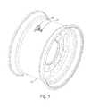
- FIG. 1is an orthographic view of a TPMS wheel mounting bracket extending from the outer surface of a vehicle wheel rim.
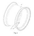
- FIG. 2is an orthographic view of the TPMS wheel mounting bracket extending from the inner surface of a vehicle wheel rim.
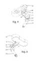
- FIG. 3is an exploded orthographic view of the TPMS wheel mounting bracket shown with the prior art elements that are used with the inventive bracket.
- FIG. 4is an upper side orthographic view of the TPMS wheel mounting bracket attached to the TPMS and to an air inlet tube.
- FIG. 5is a lower side orthographic view of the TPMS wheel mounting bracket attached to the TPMS and to the air inlet tube.
- FIG. 6is a top plan view of the TPMS wheel mounting bracket attached to the TPMS and to the air inlet tube.
- FIG. 7is a bottom plan view of the TPMS wheel mounting bracket attached to the TPMS and to the air inlet tube.
- FIG. 8is a side elevational view of the TPMS wheel mounting bracket.
- FIG. 9is a bottom plan view of the TPMS wheel mounting bracket.
- FIG. 10is a top plan view of the TPMS wheel mounting bracket.
- FIG. 11is a front elevational view of the TPMS wheel mounting bracket.
- FIG. 12is a rear elevational view of the TPMS wheel mounting bracket.
- FIG. 13is an orthographic top view of the TPMS wheel mounting bracket having laterally extended horizontal sides.
- FIG. 14is a side elevational view of the TPMS wheel mounting bracket having laterally extended horizontal sides.
- FIG. 15is a top plan view of the TPMS wheel mounting bracket having laterally extended horizontal sides.
- the best mode for carrying out the inventionis presented in terms that disclose a preferred embodiment of a tire pressure monitoring system (TPMS) wheel monitoring bracket that is designed to attach a TPMS to the rim of a vehicle wheel.
- the preferred embodiment of the TPMS wheel mounting bracket 10functions in combination with a vehicle wheel rim 50 that includes a tire-valve attachment cavity 52 having an air passage bore 54 , a TPMS 56 having a bracket attachment bore 58 , and an air inlet tube 60 .
- the air inlet tube 60as shown best in FIG. 3 , has an upper end 62 and a lower end 64 .
- a wheel rim attachment nut 66which has a substantially centered air passage bore 68 that intersects with the air passage on the air inlet tube 60 .
- the wheel rim attachment nut 66has a hexagonal head that is dimensioned to fit into the tire-valve attachment cavity 52 located on the vehicle wheel rim 50 .
- the TPMS wheel mounting bracket 10is shown attached to the vehicle wheel rim 50 in FIGS. 1 and 2 .
- the air inlet tube 60includes a set of upper tube threads 70 that extend downward from the upper end 62 of the tube 60 , and a set of lower tube threads 72 that extend upward from the lower end 64 of the air inlet tube 60 .
- the air inlet tube 60preferably has an inward displacement and also utilizes an air check valve 74 that is inserted into the lower end 64 of the air inlet tube 60 .
- Also attached to the air inlet tube 60is a resilient upper washer 76 that interfaces with the lower surface of the wheel rim attachment nut 66 , and a resilient lower washer 78 .
- the resilient upper washer 76can be imbedded into a groove on the nut or can be comprised of an O-ring.
- the lower washer 78can be designed to include an inward circular protrusion 80 , and an optional air inlet tube cap 84 .
- an air-inlet tube securing nut 82is attached to the set of upper tube threads 70 , as shown best in FIGS. 4 and 5 .
- the TPMS wheel mounting bracket 10is shown attached to the TPMS 56 and to the air inlet tube 60 in FIGS. 4-7 .
- the TPMS mounting bracket 10is the primary element that comprises the invention.
- the bracket 10is integrally formed of a material selected from the group consisting of aluminum, steel, brass, copper and carbon fiber. If aluminum is used, it can be anodized to prevent oxidation and/or to produce the bracket 10 in a selectable color to identify a use for a particular wheel rim size.
- the bracket 10is comprised of a horizontal section 12 having a first end 14 , a second end 16 , and a vertical section 18 .
- the horizontal sectionincludes a wheel rim recess 24 and a tube nut recess 25 , as shown in FIGS. 8 , 9 and 10 .
- the vertical section 18integrally extends upward from the first end 14 of the horizontal section 12 and has an upper terminus 20 , and is configured as a rectangle dimensioned to fit along the confines of the TPMS structure that has the bracket attachment bore 58 .
- Located adjacent the upper terminus 20is a threaded TPMS/bracket attachment bore 22 that accepts a threaded bolt 26 .
- the bolt 26is inserted via a washer 28 into the bracket attachment bore 58 and into the threaded TPMS/bracket attachment bore 22 .
- a tube/bracket attachment bore 32Adjacent the second end 16 of the horizontal: section 12 is a tube/bracket attachment bore 32 .
- the upper surface 34 of the bore 32interfaces, via the resilient upper washer 76 , with the lower surface of the wheel rim attachment nut 66 .
- the lower surface 36 of the tube/bracket attachment bore 32interfaces with the resilient lower washer 78 .
- the wheel mounting bracket 10is located between the resilient upper washer 76 and the resilient lower washer 78 .
- the sides of the brackets horizontal section 12are laterally extended.
Landscapes
- Engineering & Computer Science (AREA)
- Mechanical Engineering (AREA)
- General Engineering & Computer Science (AREA)
- Measuring Fluid Pressure (AREA)
Abstract
Description
| PAT. NO. | INVENTOR | ISSUED |
| 4,455,716 | Leonardo | Jun. 26, 1984 |
| 5,774,048 | Ar{grave over (c)}hterholt | Jun. 30, 1998 |
| 5,987,980 | Mangafas et al | Nov. 23, 1999 |
| 6,005,480 | Banzhof et al | Dec. 21, 1999 |
| 6,612,528 | Collins et al | Sep. 2, 2003 |
| 6,799,455 | Neefeldt et al | Oct. 5, 2004 |
- is easy formed of a single piece of material,
- can be formed of various materials,
- has an inherent structural integrity,
- can be easily attached or removed,
- requires no maintenance,
- can be sold as an OEM element or as an after-market addition,
- can be utilized with various types of TPMS,
- can be attached to an aluminum or a steel wheel, and
- is cost effective from both a manufacturer's and consumer's point of view.
Claims (15)
Priority Applications (1)
| Application Number | Priority Date | Filing Date | Title |
|---|---|---|---|
| US13/793,491US8984937B1 (en) | 2013-03-11 | 2013-03-11 | Tire pressure monitoring system wheel mounting bracket |
Applications Claiming Priority (1)
| Application Number | Priority Date | Filing Date | Title |
|---|---|---|---|
| US13/793,491US8984937B1 (en) | 2013-03-11 | 2013-03-11 | Tire pressure monitoring system wheel mounting bracket |
Publications (1)
| Publication Number | Publication Date |
|---|---|
| US8984937B1true US8984937B1 (en) | 2015-03-24 |
Family
ID=52683157
Family Applications (1)
| Application Number | Title | Priority Date | Filing Date |
|---|---|---|---|
| US13/793,491Active - Reinstated2033-07-30US8984937B1 (en) | 2013-03-11 | 2013-03-11 | Tire pressure monitoring system wheel mounting bracket |
Country Status (1)
| Country | Link |
|---|---|
| US (1) | US8984937B1 (en) |
Cited By (3)
| Publication number | Priority date | Publication date | Assignee | Title |
|---|---|---|---|---|
| EP3287303A1 (en)* | 2016-08-23 | 2018-02-28 | CUB Elecparts Inc. | Fixing element for tire pressure monitoring device |
| WO2022006142A1 (en)* | 2020-06-29 | 2022-01-06 | Christopher Cox Creative | Rapid-deflate valve stem and associated systems and methods |
| US11745549B2 (en) | 2017-08-21 | 2023-09-05 | Sram. Llc | Pressure sensing assembly for a bicycle wheel |
Citations (13)
| Publication number | Priority date | Publication date | Assignee | Title |
|---|---|---|---|---|
| US3938076A (en)* | 1973-03-06 | 1976-02-10 | Nissan Motor Co., Ltd. | Vehicle tire pressure sensing device |
| US4807468A (en)* | 1987-03-17 | 1989-02-28 | Telemagnetics, Inc. | On-board tire pressure indicating system |
| US4953395A (en)* | 1988-06-15 | 1990-09-04 | Jard James E | Tire pressure indicator |
| US6340929B1 (en)* | 1998-11-19 | 2002-01-22 | Pacific Industrial Co., Ltd | Transmitter and external controller of tire inflation pressure monitor |
| US6799455B1 (en)* | 2001-08-09 | 2004-10-05 | Edward F. Neefeldt | Vehicle tire air monitor |
| US20040263324A1 (en)* | 2003-06-24 | 2004-12-30 | Sanchez Ramon A. | Tire pressure sensor body and installation method |
| US7178390B1 (en)* | 2005-02-14 | 2007-02-20 | Advanced Products Technology | Mounting assembly for tire pressure transducer |
| US7218210B2 (en)* | 2004-03-12 | 2007-05-15 | Bruce Schoenberger | Pressure sensing method and apparatus |
| US7350408B1 (en)* | 2006-11-22 | 2008-04-01 | Rogers Larry K | Apparatus and systems for integration of a sensor into a wheel |
| US8047068B2 (en)* | 2008-08-01 | 2011-11-01 | Schrader Electronics, Inc. | Snap-in tire valve |
| US8146413B1 (en)* | 2010-11-17 | 2012-04-03 | Julian Grace | Two-port tire valve stem |
| US8245747B2 (en)* | 2006-06-09 | 2012-08-21 | Michelin Recherche Et Technique S.A. | Tire valve and process for removing it |
| US8671747B1 (en)* | 2011-11-21 | 2014-03-18 | William C. Falkenborg | TPMS monitor mounting bracket |
- 2013
- 2013-03-11USUS13/793,491patent/US8984937B1/enactiveActive - Reinstated
Patent Citations (13)
| Publication number | Priority date | Publication date | Assignee | Title |
|---|---|---|---|---|
| US3938076A (en)* | 1973-03-06 | 1976-02-10 | Nissan Motor Co., Ltd. | Vehicle tire pressure sensing device |
| US4807468A (en)* | 1987-03-17 | 1989-02-28 | Telemagnetics, Inc. | On-board tire pressure indicating system |
| US4953395A (en)* | 1988-06-15 | 1990-09-04 | Jard James E | Tire pressure indicator |
| US6340929B1 (en)* | 1998-11-19 | 2002-01-22 | Pacific Industrial Co., Ltd | Transmitter and external controller of tire inflation pressure monitor |
| US6799455B1 (en)* | 2001-08-09 | 2004-10-05 | Edward F. Neefeldt | Vehicle tire air monitor |
| US20040263324A1 (en)* | 2003-06-24 | 2004-12-30 | Sanchez Ramon A. | Tire pressure sensor body and installation method |
| US7218210B2 (en)* | 2004-03-12 | 2007-05-15 | Bruce Schoenberger | Pressure sensing method and apparatus |
| US7178390B1 (en)* | 2005-02-14 | 2007-02-20 | Advanced Products Technology | Mounting assembly for tire pressure transducer |
| US8245747B2 (en)* | 2006-06-09 | 2012-08-21 | Michelin Recherche Et Technique S.A. | Tire valve and process for removing it |
| US7350408B1 (en)* | 2006-11-22 | 2008-04-01 | Rogers Larry K | Apparatus and systems for integration of a sensor into a wheel |
| US8047068B2 (en)* | 2008-08-01 | 2011-11-01 | Schrader Electronics, Inc. | Snap-in tire valve |
| US8146413B1 (en)* | 2010-11-17 | 2012-04-03 | Julian Grace | Two-port tire valve stem |
| US8671747B1 (en)* | 2011-11-21 | 2014-03-18 | William C. Falkenborg | TPMS monitor mounting bracket |
Cited By (4)
| Publication number | Priority date | Publication date | Assignee | Title |
|---|---|---|---|---|
| EP3287303A1 (en)* | 2016-08-23 | 2018-02-28 | CUB Elecparts Inc. | Fixing element for tire pressure monitoring device |
| US11745549B2 (en) | 2017-08-21 | 2023-09-05 | Sram. Llc | Pressure sensing assembly for a bicycle wheel |
| WO2022006142A1 (en)* | 2020-06-29 | 2022-01-06 | Christopher Cox Creative | Rapid-deflate valve stem and associated systems and methods |
| US12194791B2 (en) | 2020-06-29 | 2025-01-14 | Christopher Cox Creative | Rapid-deflate valve stem and associated systems and methods |
Similar Documents
| Publication | Publication Date | Title |
|---|---|---|
| US8567241B2 (en) | Adapter incorporating a TPMS onto a truck tire valve | |
| US6631637B2 (en) | Sensor mounting assembly for a vehicle tire | |
| US6799455B1 (en) | Vehicle tire air monitor | |
| US9802447B2 (en) | Tire pressure monitoring system | |
| US6851308B2 (en) | Device for fixing a pressure sensor intended to be mounted in a tire | |
| US20120234447A1 (en) | Automatic tire inflation system | |
| US8984937B1 (en) | Tire pressure monitoring system wheel mounting bracket | |
| US7089147B1 (en) | Wireless tire-pressure monitor | |
| US20070193348A1 (en) | Tire pressure gauge with data transmitter | |
| US9027397B2 (en) | Tire pressure sensor applicable to different wheel rims | |
| US20210300130A1 (en) | Vehicle wheel monitoring system | |
| US20110272038A1 (en) | Adapter incorporating TPMS onto a truck valve | |
| US8671747B1 (en) | TPMS monitor mounting bracket | |
| US20080094197A1 (en) | Tire pressure monitoring system with bidirectional communication function | |
| US6782740B2 (en) | Tire pressure indication system | |
| US20130333459A1 (en) | Valve stem for a wireless tire pressure detector | |
| US20030024463A1 (en) | Wheel-mounted tire pressure gauge | |
| US8037745B2 (en) | Sensor for tire pressure and tire pressure monitoring system having the same | |
| US7187272B2 (en) | Casing structure of transmitter of tire condition monitoring apparatus | |
| US20020097147A1 (en) | Air pressure detection device for wheel | |
| US8130089B2 (en) | Flat alert system | |
| ITCR20130005U1 (en) | LOCKING SCREW OF A TPMS TRANSDUCER WITH A "CLAMP-IN" METAL VALVE | |
| JP2005047466A (en) | Casing structure of transmitter for tire state monitoring device | |
| GB2584488A (en) | Vehicle wheel monitoring system | |
| AU2010201461B2 (en) | Wheel assembly capable of detecting and displaying wheel conditions |
Legal Events
| Date | Code | Title | Description |
|---|---|---|---|
| STCF | Information on status: patent grant | Free format text:PATENTED CASE | |
| FEPP | Fee payment procedure | Free format text:MAINTENANCE FEE REMINDER MAILED (ORIGINAL EVENT CODE: REM.); ENTITY STATUS OF PATENT OWNER: SMALL ENTITY | |
| LAPS | Lapse for failure to pay maintenance fees | Free format text:PATENT EXPIRED FOR FAILURE TO PAY MAINTENANCE FEES (ORIGINAL EVENT CODE: EXP.); ENTITY STATUS OF PATENT OWNER: SMALL ENTITY | |
| STCH | Information on status: patent discontinuation | Free format text:PATENT EXPIRED DUE TO NONPAYMENT OF MAINTENANCE FEES UNDER 37 CFR 1.362 | |
| FP | Lapsed due to failure to pay maintenance fee | Effective date:20190324 | |
| PRDP | Patent reinstated due to the acceptance of a late maintenance fee | Effective date:20200415 | |
| FEPP | Fee payment procedure | Free format text:SURCHARGE, PETITION TO ACCEPT PYMT AFTER EXP, UNINTENTIONAL. (ORIGINAL EVENT CODE: M2558); ENTITY STATUS OF PATENT OWNER: SMALL ENTITY Free format text:PETITION RELATED TO MAINTENANCE FEES GRANTED (ORIGINAL EVENT CODE: PMFG); ENTITY STATUS OF PATENT OWNER: SMALL ENTITY Free format text:PETITION RELATED TO MAINTENANCE FEES FILED (ORIGINAL EVENT CODE: PMFP); ENTITY STATUS OF PATENT OWNER: SMALL ENTITY | |
| MAFP | Maintenance fee payment | Free format text:PAYMENT OF MAINTENANCE FEE, 4TH YR, SMALL ENTITY (ORIGINAL EVENT CODE: M2551); ENTITY STATUS OF PATENT OWNER: SMALL ENTITY Year of fee payment:4 | |
| STCF | Information on status: patent grant | Free format text:PATENTED CASE | |
| FEPP | Fee payment procedure | Free format text:MAINTENANCE FEE REMINDER MAILED (ORIGINAL EVENT CODE: REM.); ENTITY STATUS OF PATENT OWNER: SMALL ENTITY | |
| FEPP | Fee payment procedure | Free format text:7.5 YR SURCHARGE - LATE PMT W/IN 6 MO, SMALL ENTITY (ORIGINAL EVENT CODE: M2555); ENTITY STATUS OF PATENT OWNER: SMALL ENTITY | |
| MAFP | Maintenance fee payment | Free format text:PAYMENT OF MAINTENANCE FEE, 8TH YR, SMALL ENTITY (ORIGINAL EVENT CODE: M2552); ENTITY STATUS OF PATENT OWNER: SMALL ENTITY Year of fee payment:8 |