US8984711B2 - Electric tool powered by a plurality of battery packs and adapter therefor - Google Patents
Electric tool powered by a plurality of battery packs and adapter thereforDownload PDFInfo
- Publication number
- US8984711B2 US8984711B2US12/888,100US88810010AUS8984711B2US 8984711 B2US8984711 B2US 8984711B2US 88810010 AUS88810010 AUS 88810010AUS 8984711 B2US8984711 B2US 8984711B2
- Authority
- US
- United States
- Prior art keywords
- battery
- battery pack
- power tool
- input terminal
- voltage
- Prior art date
- Legal status (The legal status is an assumption and is not a legal conclusion. Google has not performed a legal analysis and makes no representation as to the accuracy of the status listed.)
- Active, expires
Links
Images


Classifications
- H01M2/10—
- H—ELECTRICITY
- H02—GENERATION; CONVERSION OR DISTRIBUTION OF ELECTRIC POWER
- H02J—CIRCUIT ARRANGEMENTS OR SYSTEMS FOR SUPPLYING OR DISTRIBUTING ELECTRIC POWER; SYSTEMS FOR STORING ELECTRIC ENERGY
- H02J7/00—Circuit arrangements for charging or depolarising batteries or for supplying loads from batteries
- H02J7/0029—Circuit arrangements for charging or depolarising batteries or for supplying loads from batteries with safety or protection devices or circuits
- H02J7/00309—Overheat or overtemperature protection
- B—PERFORMING OPERATIONS; TRANSPORTING
- B25—HAND TOOLS; PORTABLE POWER-DRIVEN TOOLS; MANIPULATORS
- B25F—COMBINATION OR MULTI-PURPOSE TOOLS NOT OTHERWISE PROVIDED FOR; DETAILS OR COMPONENTS OF PORTABLE POWER-DRIVEN TOOLS NOT PARTICULARLY RELATED TO THE OPERATIONS PERFORMED AND NOT OTHERWISE PROVIDED FOR
- B25F5/00—Details or components of portable power-driven tools not particularly related to the operations performed and not otherwise provided for
- H—ELECTRICITY
- H01—ELECTRIC ELEMENTS
- H01M—PROCESSES OR MEANS, e.g. BATTERIES, FOR THE DIRECT CONVERSION OF CHEMICAL ENERGY INTO ELECTRICAL ENERGY
- H01M10/00—Secondary cells; Manufacture thereof
- H01M10/42—Methods or arrangements for servicing or maintenance of secondary cells or secondary half-cells
- H01M10/48—Accumulators combined with arrangements for measuring, testing or indicating the condition of cells, e.g. the level or density of the electrolyte
- H01M10/488—Cells or batteries combined with indicating means for external visualization of the condition, e.g. by change of colour or of light density
- H01M2/1022—
- H01M2/1027—
- H01M2/1033—
- H01M2/1061—
- H—ELECTRICITY
- H01—ELECTRIC ELEMENTS
- H01M—PROCESSES OR MEANS, e.g. BATTERIES, FOR THE DIRECT CONVERSION OF CHEMICAL ENERGY INTO ELECTRICAL ENERGY
- H01M50/00—Constructional details or processes of manufacture of the non-active parts of electrochemical cells other than fuel cells, e.g. hybrid cells
- H01M50/20—Mountings; Secondary casings or frames; Racks, modules or packs; Suspension devices; Shock absorbers; Transport or carrying devices; Holders
- H01M50/204—Racks, modules or packs for multiple batteries or multiple cells
- H01M50/207—Racks, modules or packs for multiple batteries or multiple cells characterised by their shape
- H01M50/213—Racks, modules or packs for multiple batteries or multiple cells characterised by their shape adapted for cells having curved cross-section, e.g. round or elliptic
- H—ELECTRICITY
- H01—ELECTRIC ELEMENTS
- H01M—PROCESSES OR MEANS, e.g. BATTERIES, FOR THE DIRECT CONVERSION OF CHEMICAL ENERGY INTO ELECTRICAL ENERGY
- H01M50/00—Constructional details or processes of manufacture of the non-active parts of electrochemical cells other than fuel cells, e.g. hybrid cells
- H01M50/20—Mountings; Secondary casings or frames; Racks, modules or packs; Suspension devices; Shock absorbers; Transport or carrying devices; Holders
- H01M50/244—Secondary casings; Racks; Suspension devices; Carrying devices; Holders characterised by their mounting method
- H—ELECTRICITY
- H01—ELECTRIC ELEMENTS
- H01M—PROCESSES OR MEANS, e.g. BATTERIES, FOR THE DIRECT CONVERSION OF CHEMICAL ENERGY INTO ELECTRICAL ENERGY
- H01M50/00—Constructional details or processes of manufacture of the non-active parts of electrochemical cells other than fuel cells, e.g. hybrid cells
- H01M50/20—Mountings; Secondary casings or frames; Racks, modules or packs; Suspension devices; Shock absorbers; Transport or carrying devices; Holders
- H01M50/247—Mountings; Secondary casings or frames; Racks, modules or packs; Suspension devices; Shock absorbers; Transport or carrying devices; Holders specially adapted for portable devices, e.g. mobile phones, computers, hand tools or pacemakers
- H—ELECTRICITY
- H01—ELECTRIC ELEMENTS
- H01M—PROCESSES OR MEANS, e.g. BATTERIES, FOR THE DIRECT CONVERSION OF CHEMICAL ENERGY INTO ELECTRICAL ENERGY
- H01M50/00—Constructional details or processes of manufacture of the non-active parts of electrochemical cells other than fuel cells, e.g. hybrid cells
- H01M50/20—Mountings; Secondary casings or frames; Racks, modules or packs; Suspension devices; Shock absorbers; Transport or carrying devices; Holders
- H01M50/267—Mountings; Secondary casings or frames; Racks, modules or packs; Suspension devices; Shock absorbers; Transport or carrying devices; Holders having means for adapting to batteries or cells of different types or different sizes
- H—ELECTRICITY
- H01—ELECTRIC ELEMENTS
- H01M—PROCESSES OR MEANS, e.g. BATTERIES, FOR THE DIRECT CONVERSION OF CHEMICAL ENERGY INTO ELECTRICAL ENERGY
- H01M50/00—Constructional details or processes of manufacture of the non-active parts of electrochemical cells other than fuel cells, e.g. hybrid cells
- H01M50/20—Mountings; Secondary casings or frames; Racks, modules or packs; Suspension devices; Shock absorbers; Transport or carrying devices; Holders
- H01M50/296—Mountings; Secondary casings or frames; Racks, modules or packs; Suspension devices; Shock absorbers; Transport or carrying devices; Holders characterised by terminals of battery packs
- H—ELECTRICITY
- H01—ELECTRIC ELEMENTS
- H01M—PROCESSES OR MEANS, e.g. BATTERIES, FOR THE DIRECT CONVERSION OF CHEMICAL ENERGY INTO ELECTRICAL ENERGY
- H01M50/00—Constructional details or processes of manufacture of the non-active parts of electrochemical cells other than fuel cells, e.g. hybrid cells
- H01M50/50—Current conducting connections for cells or batteries
- H01M50/572—Means for preventing undesired use or discharge
- H01M50/574—Devices or arrangements for the interruption of current
- H—ELECTRICITY
- H02—GENERATION; CONVERSION OR DISTRIBUTION OF ELECTRIC POWER
- H02J—CIRCUIT ARRANGEMENTS OR SYSTEMS FOR SUPPLYING OR DISTRIBUTING ELECTRIC POWER; SYSTEMS FOR STORING ELECTRIC ENERGY
- H02J7/00—Circuit arrangements for charging or depolarising batteries or for supplying loads from batteries
- H02J7/0042—Circuit arrangements for charging or depolarising batteries or for supplying loads from batteries characterised by the mechanical construction
- H02J7/0045—Circuit arrangements for charging or depolarising batteries or for supplying loads from batteries characterised by the mechanical construction concerning the insertion or the connection of the batteries
- H—ELECTRICITY
- H02—GENERATION; CONVERSION OR DISTRIBUTION OF ELECTRIC POWER
- H02J—CIRCUIT ARRANGEMENTS OR SYSTEMS FOR SUPPLYING OR DISTRIBUTING ELECTRIC POWER; SYSTEMS FOR STORING ELECTRIC ENERGY
- H02J7/00—Circuit arrangements for charging or depolarising batteries or for supplying loads from batteries
- H02J7/0063—Circuit arrangements for charging or depolarising batteries or for supplying loads from batteries with circuits adapted for supplying loads from the battery
- H—ELECTRICITY
- H02—GENERATION; CONVERSION OR DISTRIBUTION OF ELECTRIC POWER
- H02J—CIRCUIT ARRANGEMENTS OR SYSTEMS FOR SUPPLYING OR DISTRIBUTING ELECTRIC POWER; SYSTEMS FOR STORING ELECTRIC ENERGY
- H02J7/00—Circuit arrangements for charging or depolarising batteries or for supplying loads from batteries
- H02J7/007—Regulation of charging or discharging current or voltage
- H02J7/00712—Regulation of charging or discharging current or voltage the cycle being controlled or terminated in response to electric parameters
- H02J7/007182—Regulation of charging or discharging current or voltage the cycle being controlled or terminated in response to electric parameters in response to battery voltage
- A—HUMAN NECESSITIES
- A01—AGRICULTURE; FORESTRY; ANIMAL HUSBANDRY; HUNTING; TRAPPING; FISHING
- A01G—HORTICULTURE; CULTIVATION OF VEGETABLES, FLOWERS, RICE, FRUIT, VINES, HOPS OR SEAWEED; FORESTRY; WATERING
- A01G20/00—Cultivation of turf, lawn or the like; Apparatus or methods therefor
- A01G20/40—Apparatus for cleaning the lawn or grass surface
- A01G20/43—Apparatus for cleaning the lawn or grass surface for sweeping, collecting or disintegrating lawn debris
- A01G20/47—Vacuum or blower devices
- B—PERFORMING OPERATIONS; TRANSPORTING
- B23—MACHINE TOOLS; METAL-WORKING NOT OTHERWISE PROVIDED FOR
- B23B—TURNING; BORING
- B23B2260/00—Details of constructional elements
- B23B2260/024—Batteries
- H—ELECTRICITY
- H01—ELECTRIC ELEMENTS
- H01M—PROCESSES OR MEANS, e.g. BATTERIES, FOR THE DIRECT CONVERSION OF CHEMICAL ENERGY INTO ELECTRICAL ENERGY
- H01M10/00—Secondary cells; Manufacture thereof
- H01M10/05—Accumulators with non-aqueous electrolyte
- H01M10/052—Li-accumulators
- H01M10/0525—Rocking-chair batteries, i.e. batteries with lithium insertion or intercalation in both electrodes; Lithium-ion batteries
- H—ELECTRICITY
- H01—ELECTRIC ELEMENTS
- H01M—PROCESSES OR MEANS, e.g. BATTERIES, FOR THE DIRECT CONVERSION OF CHEMICAL ENERGY INTO ELECTRICAL ENERGY
- H01M10/00—Secondary cells; Manufacture thereof
- H01M10/05—Accumulators with non-aqueous electrolyte
- H01M10/058—Construction or manufacture
- H—ELECTRICITY
- H01—ELECTRIC ELEMENTS
- H01M—PROCESSES OR MEANS, e.g. BATTERIES, FOR THE DIRECT CONVERSION OF CHEMICAL ENERGY INTO ELECTRICAL ENERGY
- H01M2200/00—Safety devices for primary or secondary batteries
- H01M2200/10—Temperature sensitive devices
- H01M2200/103—Fuse
- H—ELECTRICITY
- H01—ELECTRIC ELEMENTS
- H01M—PROCESSES OR MEANS, e.g. BATTERIES, FOR THE DIRECT CONVERSION OF CHEMICAL ENERGY INTO ELECTRICAL ENERGY
- H01M2220/00—Batteries for particular applications
- H01M2220/30—Batteries in portable systems, e.g. mobile phone, laptop
- H—ELECTRICITY
- H01—ELECTRIC ELEMENTS
- H01M—PROCESSES OR MEANS, e.g. BATTERIES, FOR THE DIRECT CONVERSION OF CHEMICAL ENERGY INTO ELECTRICAL ENERGY
- H01M6/00—Primary cells; Manufacture thereof
- H01M6/42—Grouping of primary cells into batteries
- H02J2007/004—
- H—ELECTRICITY
- H02—GENERATION; CONVERSION OR DISTRIBUTION OF ELECTRIC POWER
- H02J—CIRCUIT ARRANGEMENTS OR SYSTEMS FOR SUPPLYING OR DISTRIBUTING ELECTRIC POWER; SYSTEMS FOR STORING ELECTRIC ENERGY
- H02J7/00—Circuit arrangements for charging or depolarising batteries or for supplying loads from batteries
- H02J7/00032—Circuit arrangements for charging or depolarising batteries or for supplying loads from batteries characterised by data exchange
- H02J7/00036—Charger exchanging data with battery
- H—ELECTRICITY
- H02—GENERATION; CONVERSION OR DISTRIBUTION OF ELECTRIC POWER
- H02J—CIRCUIT ARRANGEMENTS OR SYSTEMS FOR SUPPLYING OR DISTRIBUTING ELECTRIC POWER; SYSTEMS FOR STORING ELECTRIC ENERGY
- H02J7/00—Circuit arrangements for charging or depolarising batteries or for supplying loads from batteries
- H02J7/0029—Circuit arrangements for charging or depolarising batteries or for supplying loads from batteries with safety or protection devices or circuits
- H02J7/00306—Overdischarge protection
- Y—GENERAL TAGGING OF NEW TECHNOLOGICAL DEVELOPMENTS; GENERAL TAGGING OF CROSS-SECTIONAL TECHNOLOGIES SPANNING OVER SEVERAL SECTIONS OF THE IPC; TECHNICAL SUBJECTS COVERED BY FORMER USPC CROSS-REFERENCE ART COLLECTIONS [XRACs] AND DIGESTS
- Y02—TECHNOLOGIES OR APPLICATIONS FOR MITIGATION OR ADAPTATION AGAINST CLIMATE CHANGE
- Y02E—REDUCTION OF GREENHOUSE GAS [GHG] EMISSIONS, RELATED TO ENERGY GENERATION, TRANSMISSION OR DISTRIBUTION
- Y02E60/00—Enabling technologies; Technologies with a potential or indirect contribution to GHG emissions mitigation
- Y02E60/10—Energy storage using batteries
- Y—GENERAL TAGGING OF NEW TECHNOLOGICAL DEVELOPMENTS; GENERAL TAGGING OF CROSS-SECTIONAL TECHNOLOGIES SPANNING OVER SEVERAL SECTIONS OF THE IPC; TECHNICAL SUBJECTS COVERED BY FORMER USPC CROSS-REFERENCE ART COLLECTIONS [XRACs] AND DIGESTS
- Y02—TECHNOLOGIES OR APPLICATIONS FOR MITIGATION OR ADAPTATION AGAINST CLIMATE CHANGE
- Y02P—CLIMATE CHANGE MITIGATION TECHNOLOGIES IN THE PRODUCTION OR PROCESSING OF GOODS
- Y02P70/00—Climate change mitigation technologies in the production process for final industrial or consumer products
- Y02P70/50—Manufacturing or production processes characterised by the final manufactured product
Definitions
- the present inventionrelates to an electric power tool powered by a plurality of battery packs and an adapter therefor.
- U.S. Pat. No. 5,028,858discloses an electric power tool that simultaneously uses two battery packs as a power source.
- the two battery packsare connected in series so that a high voltage is supplied to an electric motor of the electric power tool.
- a higher voltage output suitable for power-intensive operationscan be generated, which output is higher than is possible when only one battery pack is used as the power source.
- the battery packsWhen battery packs are connected in series, the battery packs can be damaged in some situations. For example, when the charge states of the two battery packs differ, one battery pack can become over-discharged and then may be charged by the other battery pack in the reverse direction (i.e. reverse charging). In this case, the over-discharged battery pack may be damaged so seriously that it is no longer useable.
- U.S. Pat. No. 5,028,858disclosed the use of two light-emitting diodes for indicating the respective charge states of the two battery packs.
- the battery packscan still be over-discharged or become overheated unless the user can see the indicators properly and easily.
- the usermust diligently watch all of the indicators. If the user does not see an indicator that is indicating an abnormality, because the indicator is located in a position not readily visible to the user, the battery pack corresponding to the indicator can still be over-discharged or become overheated.
- this problemis addressed by arranging a plurality of indicators configured to indicate at least one condition of each respective battery pack such that all of the indicators are simultaneously viewable by the electric power tool user. Therefore, the information being communicated by all of the indicators can be conveniently and reliably conveyed to the user, such that the likelihood of a battery abnormality, which is being indicated for one or more of the battery packs, being overlooked is substantially reduced.
- an electric power toolpreferably comprises a main body supporting a tool and an electric motor housed in the main body.
- a plurality of first battery interfacesis provided and each battery interface is configured to removably receive or attach one first battery pack.
- the plurality of first battery interfaceselectrically connect a plurality of attached first battery packs in series with the electric motor.
- a plurality of indicatorsis provided and each indicator is configured to indicate at least one condition of one first battery pack attached to one of the first battery interfaces.
- the plurality of indicatorsis arranged such that all of the indicators are simultaneously viewable or visible to a single tool user.
- the tool usercan conveniently and reliably view or see all of the indicators simultaneously and thus can visually recognize the respective conditions of the attached battery packs simultaneously.
- the tool usercan immediately stop the usage of the electric power tool and thereby avoid unnecessary, and possibly irreparable, damage to the battery pack(s).
- cordless electric power toolincluding but not limited to electric power tools for processing metals, electric power tools for processing wood, electric power tools for processing stone, and electric power tools for gardening.
- specific examplesinclude, but are not limited to, electric drills, electric impact and screw drivers, electric impact wrenches, electric grinders, electric circular saws, electric reciprocating saws, electric jig saws, electric band saws, electric hammers, electric cutters, electric chain saws, electric planers, electric nailers (including electric rivet guns), electric staplers, electric shears, electric hedge trimmers, electric lawn clippers, electric lawn mowers, electric brush cutters, electric blowers (leaf blowers), electric flashlights, electric concrete vibrators and electric vacuum cleaners.
- each battery packcomprises a plurality of lithium-ion cells and the nominal voltage of the battery packs is equal to or greater than 7.0 volts, more preferably equal to or greater than 12.0 volts and even more preferably equal to or greater than 18.0 volts.
- the present teachingsare advantageous for preventing the lithium-ion cells from over-discharging and becoming overheated, thereby lengthening the service life of the battery packs.
- an electric power tool that normally operates at a rated voltage of 36 voltsis preferably driven by two battery packs, each comprising a plurality of lithium-ion cells and each having a nominal voltage of 18 volts.
- the electric power tool having a higher outputcan be operated with the readily-available lower-voltage battery packs.
- the higher-voltage electric power toole.g., a 36 volt tool
- the higher-voltage electric power toolcan be used even if a corresponding high-voltage battery pack (i.e. a 36 volt battery pack) is not available to the user.
- Such an embodimentis also advantageous, because the lower-voltage battery pack (e.g., an 18 volt battery pack) can also be used with corresponding lower-voltage power tools (e.g., an 18 volt tool), thereby providing greater flexibility and convenience to the user.
- the lower-voltage battery packe.g., an 18 volt battery pack
- corresponding lower-voltage power toolse.g., an 18 volt tool
- a battery pack having a nominal voltage of 18 voltsincludes at least five lithium-ion cells connected in series.
- the battery pack having a nominal voltage of 18 voltsmay also include, for example, ten lithium-ion cells, wherein five pairs of lithium-ion cells are connected in parallel, and the five pairs of parallel-connected lithium-ion cells are connected in series, whereby a voltage of 18 volts is output.
- a battery pack having a nominal voltage of 18 voltscan also include 15 or more lithium-ion cells by using such parallel- and series-connected cells. The higher the number of lithium-ion cells, the greater the capacity of the battery pack and consequently the smaller the electric current flowing in each lithium-ion cell during discharge of the battery due to a load being driven thereby.
- FIG. 1shows a group of products according to one embodiment of the present teachings
- FIG. 2shows a high-voltage electric power tool that simultaneously uses two low-voltage battery packs as a power source
- FIG. 3is a top view illustrating the two low-voltage battery packs detached from the main body of the high-voltage electric tool of FIG. 2 ;
- FIG. 4is a bottom view illustrating the two low-voltage battery packs detached from the main body of the high-voltage electric tool of FIG. 2 ;
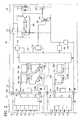
- FIG. 5is a schematic circuit diagram illustrating an electric circuit of the high-voltage electric tool of FIG. 2 ;
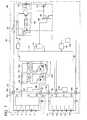
- FIG. 6is a modified example of the electric circuit of FIG. 5 having a bypass circuit added thereto;
- FIG. 7is a modified example of the electric circuit of FIG. 5 , in which the position of the connection to the power supply circuit for the main controller has been changed;
- FIG. 8is a modified example of the electric circuit of FIG. 5 , in which the position of the connection to the power supply circuit for the main controller has been changed and the bypass circuit has been added;
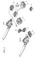
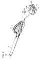
- FIG. 9shows two low-voltage battery packs connected to the main body of a high-voltage electric tool via an adapter having a cord connecting a pack side unit with a main body side unit;
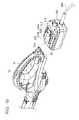
- FIG. 10shows the main body side unit of the adapter of FIG. 9 in greater detail
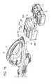
- FIG. 11shows the pack side unit of the adapter of FIG. 9 in greater detail
- FIG. 12is a schematic circuit diagram showing a representative electric circuit of the adapter of FIGS. 9-11 ;
- FIG. 13is a modified example of the electric circuit of FIG. 12 having a bypass circuit added thereto;
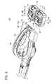
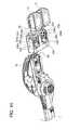
- FIG. 14shows two low-voltage battery packs connected to the main body of a high-voltage electric tool via an integrated or one-piece adapter
- FIG. 15shows an upper portion of the integrated adapter of FIG. 14 in greater detail
- FIG. 16shows a lower portion of the integrated adapter of FIG. 14 in greater detail
- FIG. 17shows a known low-voltage electric tool using one low-voltage battery pack as a power source
- FIG. 18is a bottom view corresponding to FIG. 17 after the low-voltage battery pack has been detached from the main body of the low-voltage electric tool;
- FIG. 19shows the low-voltage battery pack in greater detail
- FIG. 20shows a known high-voltage electric tool having one high-voltage battery pack as a power source
- FIG. 21is a top view illustrating the high-voltage battery pack detached from the main body of the high-voltage electric tool.
- FIG. 22is a bottom view illustrating the high-voltage battery pack detached from the main body of the high-voltage electric tool.
- FIG. 1shows an exemplary, non-limiting group of cordless power tool products according to one embodiment of the present teachings.
- the group of productsincludes two types of battery packs 10 , 30 , three types of electric power tools 50 , 70 , 100 , and two types of adapters 200 , 300 .
- the “high-voltage” electric power tool 70is normally intended to use a single “high-voltage” battery pack 30 as a power source.
- the adapters 200 , 300may serve to electrically connect a plurality of “low-voltage” battery packs 10 to a main body 72 of the electric power tool 70 so that the electric power tool 70 is supplied with the same or substantially the same voltage as the “high-voltage” battery pack 30 .
- the first battery pack 10has a nominal voltage of 18 volts and the second battery pack 30 has a nominal voltage of 36 volts.
- the first battery pack 10 having the nominal voltage of 18 voltswill also be referred to as a “low-voltage battery pack 10 ” and the second battery pack 30 having the nominal voltage of 36 volts will also be referred to as a “high-voltage battery pack 30 ”.
- the low-voltage battery pack 10comprises (at least) five lithium-ion cells connected in series.
- the high-voltage battery pack 30comprises (at least) ten lithium-ion cells connected in series.
- the two types of battery packs 10 , 30are preferably rechargeable using a battery charger (not shown in the figures) after being used as power sources for the electric tools 50 , 70 , 100 . Further, the two types of battery packs 10 , 30 are preferably so-called “slide-type” battery packs that are attached by sliding into or onto corresponding engagement portions of the electric power tools 50 , 70 , 100 , the adapters 200 , 300 or the charger. Such battery packs 10 , 30 have already been put to practical use.
- the low-voltage battery pack 10 with the nominal voltage of 18 voltshas been widely used.
- the structure of the battery pack connectionis not particularly limited and a wide variety of battery pack connection mechanisms known in the art also may be advantageously utilized with the present teachings.
- the low-voltage battery pack 10can incorporate, for example, ten lithium-ion cells, rather than five lithium-ion cells, as was discussed above at the end of the Summary section.
- the ten lithium-ion cellscomprise five pairs of lithium-ion cells connected in parallel, and the five pairs of parallel-connected lithium-ion cells are connected in series to output a voltage of 18 volts.
- the high-voltage battery pack 30can incorporate, for example, twenty lithium-ion cells, rather than ten lithium-ion cells.
- the twenty lithium-ion cellscomprise ten pairs of lithium-ion cells connected in parallel and the ten pairs of parallel-connected lithium-ion cells are connected in series to output a voltage of 36 volts.
- the “low-voltage” electric power tool 50is designed to operate at a nominal voltage of 18 volts and the other two “high-voltage” electric tools 70 , 100 are designed to operate at a nominal voltage of 36 volts.
- the electric tool 50 operating at the nominal voltage of 18 voltswill be referred to as a “low-voltage electric (power) tool 50 ”
- the electric tools 70 , 100 operating at the nominal voltage of 36 voltswill be referred to as “high-voltage electric (power) tools 70 , 100 ”.
- low-voltage and high-voltageare relative terms and are merely meant to indicate that two battery packs, which normally supply currents at different voltages, and two tools, which normally operate at different voltages, are contemplated by this aspect of the present teachings. It is not necessary that the high-voltage applications are twice the voltage of the low-voltage applications or, in fact, are any particular multiple thereof.
- two low-voltage (e.g., 18-volt) battery packs 10may be connected in series to a higher-voltage electric power tool that normally operates at a rated voltage that is not a multiple of the low-voltage battery packs 10 , such as, e.g., 24 volts.
- voltage step-down circuitryis preferably provided either in the tool or in an adapter 200 , 300 that connects the battery packs 10 to the tool.
- the low-voltage electric tool 50is designed to normally use one low-voltage battery pack 10 as its sole power source.
- This low-voltage electric tool 50is for example an electric impact driver and drives a tool chuck 54 in response to the operation of a main switch 58 .
- a driver setwhich is a tool, can be mounted on the tool chuck 54 .
- Such a low-voltage electric tool 50has already been put to practical use and has been widely sold together with the low-voltage battery pack 10 having the nominal voltage of 18 volts.
- the main body 52 of the low-voltage electric tool 50includes one battery interface 60 .
- the battery interface 60is configured to removably receive or attach the low-voltage battery pack 10 , and the low-voltage battery pack 10 can be slidably received or attached therein.
- the battery interface 60has a pair of rails 62 , a positive electrode input terminal 64 a , a negative electrode input terminal 64 b , and a latch receiving hole 68 .
- a battery controller input/output terminalis also preferably provided, but is not shown in FIG. 18 .
- the low-voltage battery pack 10includes a connector 20 that can be slidingly inserted into the battery interface 60 .
- the connector 20includes a pair of rails 22 , a positive electrode output terminal 24 a , a negative electrode output terminal 24 b , and an autostop terminal 26 .
- the positive electrode output terminal 24 a of the low-voltage battery pack 10is electrically connected to the positive electrode input terminal 64 a of the main body 52
- the negative electrode output terminal 24 b of the low-voltage battery pack 10is electrically connected to the negative electrode input terminal 64 b of the main body 52 .
- the autostop terminal 26is connected to the battery controller input/output terminal.
- the low-voltage battery pack 10is also physically connected to the main body 52 of the low-voltage electric tool 50 and the battery cells 16 (see e.g., FIG. 5 ) are electrically connected with the internal circuitry of the tool 50 .
- the low-voltage battery pack 10has a latch member 12 that engages with the latch receiving hole 68 of the battery interface 60 and detachably affixes the low-voltage battery pack 10 to the battery interface 60 .
- the latch member 12can be released from the latch receiving hole 68 by operating a latch release button 14 .
- the two types of high-voltage electric tools 70 , 100will be explained below.
- the first high-voltage electric tool 70is designed to be normally operated using one high-voltage battery pack 30 as the sole power source, as will now be explained with reference to FIGS. 20 , 21 , and 22 .
- the high-voltage electric tool 70may be, e.g., an electric blower that includes a blower fan disposed in the main body 72 that is rotatably driven in response to the operation of a main switch 78 .
- the electric blower 70is an electric power tool normally used for gardening and cleaning-up purposes by propelling air from a tip 73 a of a nozzle 73 to move debris, such as dead leaves.
- the high-voltage electric tool 70 operating at a nominal voltage of 36 voltshas already been put to practical use together with the high-voltage battery pack 30 that outputs a nominal voltage of 36 volts.
- the main body 72 of the high-voltage electric tool 70has one battery interface 80 .
- the battery interface 80is configured to removably attach to the high-voltage battery pack 30 , and the high-voltage battery pack 30 can be slidably received therein.
- the battery interface 80includes a pair of rails 82 , a positive electrode input terminal 84 a , a negative electrode input terminal 84 b , a battery controller input/output terminal 86 and a latch receiving hole 88 .
- the high-voltage battery pack 30includes a connector 40 that can be slidingly inserted into the battery interface 80 , as shown in FIG. 21 .
- the connector 40includes a pair of rails 42 , a positive electrode output terminal 44 a , a negative electrode output terminal 44 b , and an autostop terminal 46 .
- the positive electrode output terminal 44 a of the high-voltage battery pack 30is connected to the positive electrode input terminal 84 a of the battery interface 80
- the negative electrode output terminal 44 b of the high-voltage battery pack 30is connected to the negative electrode input terminal 84 b of the battery interface 80 .
- the autostop terminal 46which is electrically connected to a controller of the battery pack 30 as will be discussed further below, is connected to the battery controller input/output terminal 86 .
- the high-voltage battery pack 30is electrically connected to the circuitry inside the main body 72 of the high-voltage electric tool 70 .
- the high-voltage battery pack 30has a latch member 32 that engages with the latch receiving hole 88 of the battery interface 80 and detachable affixes the high-voltage battery pack 30 to the battery interface 80 .
- the latch member 32can be released from the latch receiving hole 88 by operating a latch release button 34 .
- the connectors 20 , 40 of the low-voltage battery pack 10 and the high-voltage battery pack 30may have basically the same or similar structures. However, the sizes of the connectors 20 , 40 may differ, e.g., the spacing between the rails 22 , 42 may differ. In this case, the low-voltage battery pack 10 cannot be attached to the battery interface 80 of the high-voltage electric tool 70 , and the high-voltage battery pack 30 cannot be attached to the battery interface 60 of the low-voltage electric tool 50 . In other words, due to the size differences in the connectors 20 , 40 , the battery interface 80 is a dedicated interface for the high-voltage battery pack 30 , and the battery interface 60 is a dedicated interface for the low-voltage battery pack 10 . Further, in another embodiment, the interfaces 60 , 80 may be dedicated, in addition or in the alternative, based upon differences in the shapes of the connectors 20 , 40 .
- the second high-voltage electric tool 100is designed to be normally operated, on the other hand, by simultaneously using two low-voltage battery packs 10 as its power source.
- the high-voltage electric tool 100also may be an electric blower having a blower fan rotatably supported in a main body 102 that is driven in response to the operation of a main switch 108 .
- the electric blower 100is basically identical to the above-described electric blower 70 in terms of functions and applications thereof.
- the main body 102 of the high-voltage electric tool 100includes two battery interfaces 130 .
- Each battery interface 130is configured to removably and, e.g., slidably, receive or attach one low-voltage battery pack 10 .
- Each battery interface 130includes a pair of rails 132 , a positive electrode input terminal 134 a , a negative electrode input terminal 134 b , a battery controller input/output terminal 136 and a latch receiving hole 138 .
- the battery interface 130is substantially identical to the battery interface 60 of the above-described low-voltage electric tool 50 in terms of the respective structures.
- the two battery interfaces 130are arranged side by side in the rear portion of the main body 102 , and the low-voltage battery packs 10 can be inserted in the same direction.
- the two low-voltage battery packs 10 attached to the two battery interfaces 130are connected in series and supply current to the circuitry of the main body 102 at about 36 volts.
- the main body 102 of the high-voltage electric tool 100also includes two indicators 160 respectively positioned above the two battery interfaces 130 .
- Each indicator 160comprises, e.g., one or more light-emitting diodes, or another means for visually communicating battery condition information to the tool user, such as but not limited to one or more incandescent lamps and/or a display, such as an LCD.
- one of the indicators 160may indicate a charge state or level of charge of the low-voltage battery pack 10 attached to one battery interface 130
- the other indicator 160may indicate the same condition (i.e. level of charge) or another condition of the low-voltage battery pack 10 attached to the other battery interface 130 .
- both indicators 160indicate the charge state or the level of charge of the corresponding low-voltage battery pack 10 .
- the light-emitting diodecan be illuminated when the charge state drops to a level at which recharging of the battery pack 10 is necessary.
- each indicator 160indicates the charge state of its corresponding low-voltage battery pack 10 at least in two levels, e.g., a yellow “low-charge warning” and red “immediately stop tool use” indication.
- a third green “tool operation permitted” LEDalso may be optionally provided, so that the tool user can receive visual confirmation that the battery is in a suitable condition for use.
- one or more indicators 160communicate information concerning a possible battery temperature abnormality (e.g., overheating) of the corresponding low-voltage battery pack 10 , instead of or in addition to the charge state of the corresponding low-voltage battery pack 10 .
- a possible battery temperature abnormalitye.g., overheating
- the two indicators 160are arranged side by side on a rear surface 102 a of the high-voltage electric tool 100 and have the same indication direction (that is, the direction of illumination of the two light-emitting diodes is the same or substantially the same). Therefore, the user can see both indicators 160 simultaneously and can simultaneously recognize the respective charge states of the two low-voltage battery packs 10 in a convenient and reliable manner. Further, the indicators 160 are disposed above the corresponding battery interfaces 130 . Therefore, for example, if the high-voltage electric tool 100 abruptly stops, the user can immediately and conveniently determine which of the low-voltage battery packs 10 has experienced a problem or abnormality.
- the two indicators 160could be disposed in other locations that can be simultaneously viewed by the user, such as an upper surface of the main body 102 . More particularly, it is preferred that the two indicators 160 are disposed generally in the same plane, so that the user can simultaneously see the two indicators 160 from various different directions.
- one or more indicators 160can be also provided on an outer surface of each low-voltage battery pack 10 , e.g. a surface of the battery pack 10 that faces rearward when the battery pack 10 is attached to the tool 100 .
- the two battery interfaces 130are arranged side by side and can slidably receive the low-voltage battery packs 10 in the same direction.
- the two indicators 160when the two low-voltage battery packs 10 are attached to the main body 102 , the two indicators 160 will be positioned side by side in the same plane and the indication or illumination direction thereof will also be the same or substantially the same. As a result, even if the indicators 160 are disposed on the respective battery packs 10 , the user can simultaneously view the two indicators 160 from various different directions.
- Each low-voltage battery pack 10comprises five battery cells 16 connected in series and a battery controller 18 , preferably a microprocessor. Each cell 16 is preferably a lithium-ion cell and the nominal voltage thereof is 3.6 volts. The five cells 16 connected in series are connected to the positive electrode output terminal 24 a and negative electrode output terminal 24 b , and current can flow across the two terminals 24 a , 24 b at a voltage of about 18 volts. As shown in FIG.
- the negative electrode output terminal 24 b of the upper low-voltage battery pack 10is electrically connected to the positive electrode output terminal 24 a of the lower low-voltage battery pack 10 via the terminals 134 a and 134 b , which are conductively connected by a wire.
- the battery cells 16 of the two low-voltage (18 volt) battery packs 10are connected in series and supply current to the circuitry of the main body 102 at a voltage of about 36 volts.
- the battery controller 18preferably comprises an integrated circuit that includes a CPU and can execute various programs stored therein.
- the battery controller 18is electrically connected to each cell 16 and can measure the voltage of each cell 16 .
- the battery controller 18may be programmed to perform an algorithm, wherein the controller 18 determines the charge state or level of charge of each cell 16 based on the measured voltage of each cell 16 , compares the measured voltage to a predetermined, stored threshold value and then outputs an autostop signal (AS signal) to the autostop terminal 26 when at least one cell 16 is determined to require recharging based upon the comparison step.
- the autostop signalmay be a signal, e.g., indicating that a high impedance has been detected.
- the autostop signalmay preferably be a digital logic signal that is selected from one of two different voltage levels, i.e. a “1” or “0” digital signal that has a distinctly different voltage level signal as compared to a “battery normal” signal.
- the battery controller 18may be an analog circuit or a mixed analog/digital circuit (e.g., a state machine) and the battery controller 18 may output analog signals (e.g., signals having more than two voltage levels) as the autostop signal.
- the battery controller 18is not limited to outputting only “autostop” signals, but may also be configured or programmed to output a wide variety of signals, e.g., representing one or more conditions of the battery, such as battery temperature, battery voltage, battery impedance, etc.
- the main body 102is provided with a motor 176 that drives the tool (in this exemplary embodiment, a blower fan).
- the two low-voltage battery packs 10are connected in series with the motor 176 via a main switch 178 .
- the main body 102is provided with a speed adjusting circuit 190 , a power FET 194 , a gate-voltage-controlling transistor 192 , and a voltage division circuit 196 .
- the power FET 194is connected in series with the motor 176 and can shut off the electric current flowing to the motor 176 .
- the speed adjusting circuit 190performs pulse width modulation control for controlling the current flow through the power FET 194 and thus can adjust the rotational speed of the motor 176 in a manner well known in the power tool field.
- the gate-voltage-controlling transistor 192is connected to the gate of the power FET 194 and, together with the voltage division circuit 196 , can control the gate voltage of the power FET 194 .
- the main body 102is also provided with a main controller 152 , a power supply circuit 142 for the main controller 152 , a shunt resistor 150 connected in series with the motor 176 , a current detection circuit 148 that detects the electric current flowing to the motor 176 based on the voltage of the shunt resistor 150 , and an autostop signal (AS signal) input/output circuit 144 that inputs/outputs autostop signals to/from the gate-voltage-controlling transistor 192 .
- AS signalautostop signal
- the main controller 152is preferably an integrated circuit including a CPU and can execute various programs stored therein.
- the main controller 152may be programmed to perform the following algorithm. After receiving a voltage signal outputted by a current detection circuit 148 as an input signal, the main controller 152 compares the voltage signal to a pre-set, stored threshold/permissible value and then outputs an autostop signal to the gate-voltage-controlling transistor 192 via the autostop signal input/output circuit 144 when the electric current of the motor 176 exceeds the pre-set permissible value. In this case, the gate-voltage-controlling transistor 192 decreases the voltage coupled to the gate of the power FET 194 to the ground voltage, thereby shutting off the power FET 194 .
- a fuse 162 for preventing an excessive current from flowing between the motor 176 and the low-voltage battery pack 10may also optionally be provided in the circuit path between the motor 176 and the low-voltage battery pack 10 .
- the main controller 152is electrically connected to the battery controller input/output terminal (hereinafter “autostop terminal”) 136 of the battery interface 130 and can receive a signal voltage (for example, an autostop signal) from the battery controller 18 as an input signal and can output a signal voltage (for example, a discharge protection cancellation signal) to the battery controller 18 .
- autostop terminalthe battery controller input/output terminal
- a signal voltagefor example, an autostop signal
- a signal voltagefor example, a discharge protection cancellation signal
- the reference voltage of the low-voltage battery pack 10 positioned at the high-voltage side(upper side in FIG. 5 ) is 18 volts due to the series connection via terminals 24 a , 134 a , 134 b , 24 b .
- the reference voltage of the main body 102is equal to the reference voltage of the low-voltage battery pack 10 at the low-voltage side and is thus also zero volts.
- the levels of the inputted and outputted signal voltagesdiffer significantly between the main controller 152 of the main body 102 and the battery controller 18 of the upper low-voltage battery pack 10 positioned at the high-voltage side. Consequently, the signal voltages cannot be directly inputted and outputted between the controllers 18 , 152 unless a conversion (e.g., a step-down, step-up or other voltage level shift) of the signal voltages is first performed.
- the high-voltage electric tool 100 of the present embodimentalso includes two voltage level-shifters (e.g., DC-to-DC converters) 154 b , 156 b provided between the battery controller 18 of the low-voltage battery pack 10 positioned at the high-voltage side and the main controller 152 of the main body 102 .
- One level-shifter 154 bis provided on a conductive path 154 that conducts a signal voltage from the main controller 152 to the battery controller 18 and raises, preferably proportionally raises, the level of the signal voltage outputted by the main controller 152 to an acceptable or readable level for the battery controller 18 .
- the other level-shifter 156 bis provided on a conductive path 156 for conducting a signal voltage from the battery controller 18 to the main controller 152 and lowers, preferably proportionally lowers, the level of the signal voltage outputted by the battery controller 18 to an acceptable or readable level for the main controller 152 .
- signalscan be communicated (i.e. input and output) between the battery controller 18 and the main controller 152 without any problem caused by the different ranges of voltages at which the two controllers 18 , 152 operate.
- cut-off switches 154 a , 156 aare also provided between each battery controller 18 and the main controller 152 .
- One cut-off switch 154 ais provided on the conductive path 154 for conducting the signal voltage from the main controller 152 to the battery controller 18
- the other cut-off switch 156 ais provided on the conductive path 156 for conducting a signal voltage from the battery controller 18 to the main controller 152 .
- the cut-off switches 154 a , 156 aare controlled by the main controller 152 .
- the main controller 152determines that the high-voltage electric tool 100 has not been used for a predetermined time, the main controller 152 switches off the cut-off switches 154 a , 156 a , thereby electrically disconnecting the battery controllers 18 from the main controller 152 .
- leakage currentis prevented from flowing for too long of a time between the battery controllers 18 and the main controller 152 , thereby preventing the low-voltage battery pack 10 from being excessively discharged.
- the cut-off switches 154 a and 156 bare electrically connected between the main controller 152 and respective battery controllers 18 via the respective wires 154 , 156 , through which a leakage current may flow.
- the arrangement of the cut-off switch(es) of the present teachingsis not limited to the arrangement shown in the present embodiment.
- the cut-off switch(s)may be provided in one or some, but not all, of the conductive paths.
- the cut-off switch(s)may be provided between the main controller 152 and only one or some of the battery packs (e.g., only the first battery pack #1 or the second battery pack #2).
- the battery controller 18when the charge state of the cells 16 is detected as having decreased below a pre-determined threshold, the battery controller 18 outputs an autostop signal to the autostop terminal 26 , which is electrically connected to the autostop terminal 136 .
- the autostop signal outputted from the battery controller 18is input into the main controller 152 via the conductive path 156 .
- the main controller 152receives the autostop signal from the battery controller 18 and outputs an autostop signal to the gate-voltage-controlling transistor 192 .
- the autostop signal outputted by the main controller 152is conducted to the gate of the gate-voltage-controlling transistor 192 via an autostop signal input/output circuit 144 .
- the gate-voltage-controlling transistor 192is turned on (i.e. becomes conductive), the power FET 194 is shut off, and current supply to the motor 176 is stopped.
- the low-voltage battery pack 10is thus prevented from being over or excessively discharged.
- the indicator (LED of indication circuit) 160is preferably illuminated.
- the main controller 152selectively illuminates only the indicator 160 corresponding to the low-voltage battery pack 10 that has outputted the autostop signal. As a result, the user can immediately determine which low-voltage battery pack 10 requires charging.
- the high-voltage electric tool 100has two battery interfaces 130 configured to removably receive respective low-voltage battery packs 10 and can simultaneously use two low-voltage battery packs 10 as the power source.
- the two low-voltage battery packs 10are connected in series to the motor 176 and supply a voltage of 36 volts to the motor 176 .
- the high-voltage electric tool 100 with a rated voltage of 36 voltsis driven by two low-voltage battery packs 10 , each having a nominal voltage of 18 volts.
- the usercan power the high-voltage electric tool 100 by using already available low-voltage battery packs 10 , without having to purchase the high-voltage battery pack 30 and a charger therefor.
- Each low-voltage battery pack 10also can be used individually as a sole power source for the low-voltage electric tool 50 . Therefore, the user can effectively use the already available low-voltage battery packs 10 and the battery charger therefor.
- FIG. 6illustrates an example in which the electric circuit of the high-voltage electric tool 100 has been modified.
- two bypass circuits 158are added to the circuit shown in FIG. 5 .
- One bypass circuit 158is provided for each respective low-voltage battery pack 10 connected with the main controller 152 .
- Each bypass circuit 158connects the positive electrode input terminal 134 a with the negative electrode input terminal 134 b for one battery pack 10 via a diode 158 a .
- the bypass circuit 158connects the positive electrode output terminal 24 a with the negative electrode output terminal 24 b of each low-voltage battery pack 10 via the diode 158 a .
- one bypass circuit 158is provided for each of the battery packs 10 connected with the main controller 152 .
- the bypass circuitmay be provided between only some of the battery packs (e.g., only the first battery pack #1 or the second battery pack #2).
- the anode of the diode 158 ais connected to the negative electrode input terminal 134 b
- the cathode of the diode 158 ais connected to the positive electrode input terminal 134 a . Therefore, electric current normally does not flow in the diode 158 a , and the positive electrode output terminal 24 a and the negative electrode output terminal 24 b of the low-voltage battery pack 10 are electrically disconnected. However, when the low-voltage battery pack 10 becomes over-discharged and a reverse voltage is generated across the output terminals 24 a , 24 b of the low-voltage battery pack 10 , electric current is caused to flow in the diode 158 a .
- a fuse 158 balso may be optionally provided in the bypass circuit 158 . In this case, if a large current flows in the bypass circuit 158 , the bypass circuit 158 will be physically disconnected by the fuse 158 b , which has melted or otherwise broken the connection due to the excessive current. As a result, any damage caused to the low-voltage battery pack 10 can be minimized or prevented, for example, even when Zener breakdown occurs in the diode 158 a .
- the fuse 158 bis preferably accessible by the user so that it can be replaced, in case it is broken.
- FIG. 7illustrates another modified example of the electric circuit of the high-voltage electric tool 100 .
- the attachment position of the power supply for the main controller 152 in the circuit shown in FIG. 5has been changed.
- the main switch 178is inserted between the low-voltage battery pack 10 and the power supply circuit 142 .
- the main switch 178is switched off, the current flow to the main controller 152 is simultaneously shut off.
- the main controller 152can be prevented from unnecessarily consuming power in an inactive state of the high-voltage electric tool 100 .
- FIG. 8illustrates another modified example of the electric circuit of the high-voltage electric tool 100 .
- two bypass circuits 158are added to the circuit shown in FIG. 7 .
- the structure, functions, and effect of the bypass circuits 158are same as described with reference to the embodiment shown in FIG. 6 .
- FIGS. 9 , 10 , and 11Two types of adapters 200 , 300 are also disclosed in the present teachings, namely a corded adapter 200 and an integrated adapter 300 .
- the corded adapter 200will be explained first with reference to FIGS. 9 , 10 , and 11 .
- the tool shown in FIGS. 9 and 10corresponds to the tool 70 shown in FIGS. 19-22 , which was described above and is incorporated herein by reference.
- the adapter 200is configured to connect a plurality of low-voltage battery packs 10 to the high-voltage electric tool 70 .
- the adapter 200is provided with a main body side unit 202 configured to be detachably attached to the main body 72 of the high-voltage electric tool 70 , a pack side unit 206 configured to removably receive or attach a plurality of low-voltage battery packs 10 , and an electric cord 204 that physically and electrically connects the main body side unit 202 to the pack side unit 206 .
- An attachment hook 206 aoptionally may be provided on the pack side unit 206 to enable it to be attached to the user's clothing or belt or another article supported by the user's body, so that the adapter 200 and attached battery packs 10 can be conveniently carried during operation of the tool 70 .
- the main body side unit 202has an outer contour that generally conforms to the outer contour of the high-voltage battery pack 30 .
- a connector 220is provided on the main body side unit 202 in the same manner as on the high-voltage battery pack 30 .
- the connector 220can be slidingly inserted into the battery interface 80 provided on the main body 72 of the high-voltage electric tool 70 .
- the connector 220includes a pair of rails 222 , a positive electrode output terminal 224 a , a negative electrode output terminal 224 b , and an autostop terminal 226 .
- the main body side unit 202When the main body side unit 202 is attached to the battery interface 80 , the positive electrode output terminal 224 a of the main body side unit 202 is connected to the positive electrode input terminal 84 a of the battery interface 80 , and the negative electrode output terminal 224 b of the main body side unit 202 is connected to the negative electrode input terminal 84 b of the battery interface 80 . Further, the autostop terminal 226 is connected to the battery controller input/output (autostop) terminal 86 . As a result, the main body side unit 202 is electrically connected to the internal circuitry of the main body 72 of the high-voltage electric tool 70 . Further, the main body side unit 202 has a latch member 212 that is engaged with the latch receiving hole 88 (see FIG. 22 ) of the battery interface 80 and is configured to detachably affix the main body side unit 202 to the battery interface 80 . This engagement of the latch receiving hole 88 with the latch member 212 can be released by the latch release button 214 .
- the pack side unit 206includes two battery interfaces 230 .
- Each battery interface 230can removably receive or attach one low-voltage battery pack 10 , and the low-voltage battery pack 10 can be slidably received thereby.
- the battery interface 230has a pair of rails 232 , a positive electrode input terminal 234 a , a negative electrode input terminal 234 b , a battery controller input/output (autostop) terminal 236 and a latch receiving hole 238 .
- the battery interface 230is substantially identical to the battery interface 60 of the low-voltage electric tool 50 explained hereinabove with respect to FIGS. 17 and 18 and incorporated herein by reference.
- the two battery interfaces 230are arranged side by side on the lower surface of the pack side unit 206 and the low-voltage battery packs 10 are respectively inserted therein in the same direction.
- the two low-voltage battery packs 10 attached to the pack side unit 206are connected in series to the positive electrode output terminal 224 a and the negative electrode output terminal 224 b of the connector 220 .
- the two low-voltage battery packs 10supply current to the internal circuitry of the main body 72 of the high-voltage electric tool 70 at a voltage of about 36 volts.
- the adapter 200enables the power tool 70 having the battery interface 80 dedicated for the high-voltage battery pack 30 to be connected to the low-voltage battery packs 10 and to be driven thereby.
- the autostop terminal 26 of the battery pack 10is connected to the autostop terminal 236 of the pack side unit 206 .
- the pack side unit 206also includes two indicators 260 .
- the two indicators 260are respectively positioned above the two battery interfaces 230 .
- Each indicator 260is for example a light-emitting diode, but may be any other device that is capable of visually communicating information about the status of the attached battery pack 10 , such as one or more incandescent lamps or one or more LCDs.
- the teachings concerning the indicator 160 discussed above with respect to the embodiment of FIGS. 2-4are equally applicable to the present embodiment and thus the above-teachings concerning the indicator 160 are incorporated herein.
- one indicator 260may indicate a charge state or level of charge of the low-voltage battery pack 10 attached to one battery interface 230
- the other indicator 260may indicate the same condition (level of charge) or another condition of the low-voltage battery pack 10 attached to the other battery interface 230
- Each indicator 260preferably indicates at least the charge state of its corresponding low-voltage battery pack 10 .
- the light-emitting diodecan be illuminated when the charge state drops below a level at which recharging becomes necessary.
- the indicator 260indicates the charge state of its corresponding low-voltage battery pack 10 at least in two levels.
- the indicator 260indicates a temperature abnormality of its corresponding low-voltage battery pack 10 , instead of or in addition to the charge state thereof.
- the two indicators 260are preferably arranged side by side on one surface of the pack side unit 206 and have the same or substantially the same indication direction (that is, the same or substantially the same illumination direction of light-emitting diodes). Therefore, the user can see the two indicators 260 simultaneously and can simultaneously recognize the charge states of the two low-voltage battery packs 10 . Further, the indicators 260 are preferably disposed above the corresponding battery interfaces 230 . Therefore, for example, if the high-voltage electric tool 70 abruptly stops, the user can immediately determine which low-voltage battery pack 10 has experienced a problem or abnormality.
- the two indicators 260can be also disposed, for example, on the main body side unit 202 , rather than on the pack side unit 206 .
- the two indicators 260can be also arranged in other locations that can be simultaneously viewed by the user. It is preferred that the two indicators 260 are disposed in the same plane, so that the user can simultaneously see the two indicators 260 from various directions.
- the indicator 260can be also provided in each low-voltage battery pack 10 .
- the two battery interfaces 230are arranged side by side and can receive the low-voltage battery packs 10 in the same direction. Therefore, when the two low-voltage battery packs 10 are attached to the pack side unit 206 , the two indicators 260 are positioned side by side in the same plane and the direction of illumination is also the same. The user can thus simultaneously view the two indicators 260 from various directions.
- FIG. 12An exemplary electric circuit of the adapter 200 will be explained below with reference to FIG. 12 .
- the circuit of the adapter 200is substantially identical to a part of the circuit disposed in the main body 102 of the above-described high-voltage electric tool 100 . More specifically, a combination of the circuit of the main body 72 of the high-voltage electric tool 70 and the circuit of the adapter 200 shown in FIG. 12 is substantially identical to the circuit of the main body 102 of the high-voltage electric tool 100 shown in FIG. 5 (however, the power FET 246 is absent in FIG. 5 ).
- the main body 72 of the high-voltage electric tool 70is provided with a motor 76 , a main switch 78 , a speed adjusting circuit 90 , a power FET 94 , a gate-voltage-controlling transistor 92 , and a voltage division circuit 96 .
- the configurations of these componentsmay be identical to those of the motor 176 , main switch 178 , speed adjusting circuit 190 , power FET 194 , gate-voltage-controlling transistor 192 , and voltage division circuit 196 of the main body 102 of the high-voltage electric tool 100 described above with reference to FIGS. 5-8 and therefore an explanation thereof is not necessary here.
- Two low-voltage battery packs 10are thus connected in series to the motor 76 via the adapter 200 .
- the adapter 200is provided with a main controller 252 , a power source circuit 242 , a shunt resistor 250 , a current detection circuit 248 , an autostop signal input/output circuit 244 , and a fuse 262 .
- the main controller 252is electrically connected to two indicators 260 .
- the configurations of these componentsmay be identical to those of the main controller 152 , power source circuit 142 , shunt resistor 150 , current detection circuit 148 , autostop signal input/output circuit 144 , indicator 160 , and fuse 162 in the main body 102 of the high-voltage electric tool 100 and therefore an explanation thereof also is not necessary here.
- the adapter 200is further provided with a power FET 246 between a negative electrode input terminal 234 b connected to the low-voltage battery pack 10 and a negative electrode output terminal 224 b connected to the high-voltage electric tool 70 .
- a power FET 246between a negative electrode input terminal 234 b connected to the low-voltage battery pack 10 and a negative electrode output terminal 224 b connected to the high-voltage electric tool 70 .
- the main controller 252is connected to the gate of the power FET 246 and can control the power FET 246 .
- the main controller 252may shut off the power FET 246 when the output voltage of the current detection circuit 248 exceeds a predetermined value.
- the power FET 246will be explained below.
- the connector 220 of the adapter 200is exposed.
- a voltage of about 36 voltsis generated across the positive electrode output terminal 224 a and the negative electrode output terminal 224 b in the connector 220 .
- the positive electrode output terminal 224 a and the negative electrode output terminal 224 bare disposed in a slot of the adapter 200 as shown in FIG. 10 . Therefore, foreign matter is generally prevented from coming into contact with the two output terminals 224 a , 224 b .
- the possibility of the foreign matter coming into contact with the two output terminals 224 a , 224 bcannot be completely excluded.
- the power FET 246is provided inside the adapter 200 so that, after the adapter 200 has been removed from the high-voltage electric tool 70 , if very large current is detected, the circuit and thus the current flow can be cut off by the power FET 246 .
- the main controller 252is electrically connected to an autostop terminal 236 of the battery interface 230 and can receive an input signal voltage (for example, an autostop signal) from the battery controller 18 and can output a signal voltage (for example, a discharge protection cancellation signal) to the battery controller 18 .
- Cut-off switches 254 a , 256 aare provided, respectively, in a conductive path 254 that conducts the signal voltage from the main controller 252 to the battery controller 18 and in a conductive path 256 that conducts a signal voltage from the battery controller 18 to the main controller 252 .
- level-shifters 254 b , 256 bare also provided in the conductive paths 254 , 256 , respectively, in order to adjust the voltage of signals output from the battery controller 18 of the low-voltage battery pack 10 that is positioned on the high-voltage side, as was discussed above with respect to the exemplary level shifters 154 b , 156 b of FIGS. 5-8 .
- the cutoff switches 154 a , 156 a and level shifters 154 b , 156 b described above with respect to the high-voltage electric tool 100may be used without modification in the present embodiment and therefore an explanation thereof is not necessary here.
- the high-voltage electric tool 70(which is designed to normally attach only one battery pack at the battery interface 80 ) can be operated with two low-voltage battery packs 10 .
- the two low-voltage battery packs 10By connecting the two low-voltage battery packs 10 in series to the motor 76 , it is possible to supply a voltage of about 36 volts to the motor 76 .
- the high-voltage electric tool 70 with a rated voltage of 36 voltscan be driven by two low-voltage battery packs 10 , each having a nominal voltage of 18 volts.
- the high-voltage electric tool 70can be operated using already available low-voltage battery packs 10 , without the need to purchase a high-voltage battery pack 30 that supplies a nominal voltage of 36 volts or the charger therefor.
- Each low-voltage battery pack 10can also be individually used as the sole power source for the low-voltage electric tool 50 , which operates with an 18 volt battery pack.
- FIG. 13illustrates a modified example of the electric circuit of the adapter 200 .
- two bypass circuits 258are added to the circuit shown in FIG. 12 .
- One bypass circuit 258is provided for each respective low-voltage battery pack 10 .
- the bypass circuit 258includes a diode 258 a and a fuse 258 b .
- These bypass circuits 258may be identical to the bypass circuits 158 of the high-voltage electric tool 100 described above with respect to FIGS. 6 and 8 and therefore an explanation thereof is not necessary here.
- FIGS. 14 , 15 , and 16Another (integrated) adapter 300 will be explained below with reference to FIGS. 14 , 15 , and 16 .
- the tool shown in FIGS. 14-16corresponds to the tool 70 shown in FIGS. 19-22 , which was described above and is incorporated herein by reference.
- the adapter 300also serves to connect a plurality of low-voltage battery packs 10 to the high-voltage electric tool 70 .
- the adapter 300also enables the power tool 70 having the battery interface 80 designed to receive the high-voltage battery pack 30 to be connected to the low-voltage battery packs 10 and to be driven thereby.
- the entire circuitry for this adapter 300is contained within one housing.
- the portions, which correspond to the main body side unit 202 and pack side unit 206 of the above-described adapter 200are integrated into a single housing.
- the electric circuitry of the adapter 300may be functionally identical to the circuitry of the above-described adapter 200 shown in FIG. 12 or FIG. 13 .
- the connector 220may be provided at or on the upper surface of the adapter 300 in the same manner as the connector 220 of the corded adapter 200 shown in FIG. 10 .
- the connector 220can be slidingly inserted into the battery interface 80 provided on the main body 72 of the high-voltage electric tool 70 .
- the connector 220includes a pair of rails 222 , a positive electrode output terminal 224 a , a negative electrode output terminal 224 b , and an autostop terminal 226 .
- the structures of connectors 220 in the two types of adapters 200 , 300may be substantially identical.
- the positive electrode output terminal 224 a of the adapter 300is electrically connected to the positive electrode input terminal 84 a of the battery interface 80
- the negative electrode output terminal 224 b of the adapter 300is electrically connected to the negative electrode input terminal 84 b of the battery interface 80
- the adapter 300is electrically connected to the circuitry contained in the main body 72 of the high-voltage electric tool 70 .
- the autostop terminal 86is connected to the autostop terminal 226 .
- two battery interfaces 230are provided on the lower surface of the adapter 300 in the same manner as the battery interfaces 230 of the corded adapter 200 shown in FIG. 11 .
- Each battery interface 230can removably receive or attach one low-voltage battery pack 10 , and the low-voltage battery pack 10 can be slidably received thereby.
- the battery interface 230has a pair of rails 232 , a positive electrode input terminal 234 a , a negative electrode input terminal 234 b , and a latch receiving hole 238 .
- the structures of the battery interfaces 230 of the two types of adapters 200 , 300may be substantially identical.
- the two battery interfaces 230are arranged side by side on the lower surface of the pack side unit 206 and the low-voltage battery packs 10 are respectively inserted therein in the same direction.
- the two low-voltage battery packs 10 attached to the adapter 300are connected in series to the positive electrode output terminal 224 a and the negative electrode output terminal 224 b of the connector 220 .
- the two low-voltage battery packs 10supply current to the circuitry contained in the main body 72 of the high-voltage electric tool 70 at a voltage of about 36 volts.
- the autostop terminal 26 of the battery pack 10is connected to the autostop terminal 236 of the adapter 300 .
- the adapter 300is also provided with two indicators 260 .
- the two indicators 260are disposed on the rear surface 300 a of the adapter 300 .
- the two indicators 260are respectively positioned above the two battery interfaces 230 .
- Each indicator 260comprises, e.g., a light-emitting diode or another light source, such as an incandescent light, or a display device such as an LCD, as was described above with reference to the indicator 260 of the corded adapter 200 and the indicator 160 of the embodiment of FIGS. 2-4 , which description is again incorporated herein by reference.
- the indicator 260may indicate a charge state of the low-voltage battery pack 10 attached to one battery interface 230
- the other indicator 260may indicate the same or a different condition of the low-voltage battery pack 10 attached to the other battery interface 230
- the two indicators 260are preferably arranged side by side on the rear surface 300 a of the adapter 300 . Therefore, the user can see the two indicators 260 simultaneously and can simultaneously recognize the respective charge states or other indicated condition(s) of the two low-voltage battery packs 10 .
- the indicators 260are preferably disposed above the corresponding battery interfaces 230 . Therefore, for example, if the high-voltage electric tool 70 abruptly stops, the user can immediately determine which low-voltage battery pack 10 is experiencing a problem or abnormality.
- the high-voltage electric tool 70can be operated using two low-voltage battery packs 10 .
- the two low-voltage battery packs 10By connecting the two low-voltage battery packs 10 in series to the motor 76 , it is possible to supply a voltage of about 36 volts to the motor 76 .
- the high-voltage electric tool 70 with a rated voltage of 36 voltscan be driven by two low-voltage battery packs 10 , each having a nominal voltage of 18 volts.
- the high-voltage electric tool 70can be powered using already available low-voltage battery packs 10 , without the need to purchase a high-voltage battery pack 30 having a nominal voltage of 36 volts or a charger therefor.
- Each low-voltage battery pack 10can be also individually used as the sole power source for the low-voltage electric tool 50 .
- the representative example of the low-voltage electric tool 50is an electric drill
- the representative example of the high-voltage electric tools 70 , 100is an electric blower (leaf blower).
- the present teachingsare not particularly limited to these types of electric tools and can be widely applied to a variety of types of electric tools, as was described above in the Summary section.
- present teachingshave been described with respect to a preferred usage of lithium-ion cells, the present teachings are, of course, applicable to any type of battery chemistry or technology, including but not limited to nickel-cadmium, nickel-metal-hydride, nickel-zinc, lithium iron phosphate, etc.
- the battery interface 80 of the tool 100 or the adapters 200 , 300may, of course, be modified to connect three or more battery packs 10 in series and/or in parallel.
- the first battery packs 10are not all required to have the same nominal voltage and in certain applications of the present teachings, one first battery pack 10 could have a first nominal voltage, e.g., of 12 volts, and one first battery pack 10 could have a second nominal voltage, e.g., of 18 volts, i.e. the first and second nominal voltages of the two battery packs 10 are different.
- the first battery interfaces 130 , 230are configured differently, so as to be able to ensure that only the appropriate battery pack is attachable thereto.
- the main controller 152 of the tool 70 , 100 or the main controller 252 of the adapter 200 , 300 , and its supporting circuitrymay be configured to recognize battery packs having different nominal voltages and process signals outputted from the respective CPUs of the battery packs appropriately.
- the adapters 200 , 300may be modified to only provide a voltage level-shifting function and the tool motor controlling function may be performed by an integrated circuit, e.g., a microprocessor, located in the main body 72 , 100 of the tool 70 , 100 .
- the adapters 200 , 300are not required to include the main controller 252 and instead may include, e.g., only the level-shifters 254 b , 256 b and/or the cut-off switches 254 a , 256 a .
- the adapters 200 , 300may also include the diode(s) 258 a , the fuse(s) 258 b and the indicators 260 .
- the functions of the main controller 252are performed by circuitry located in the main body 72 , 100 of the tool 70 , 100 .
- the level-shifters 254 b , 256 bpreferably supply appropriate voltage-adjusted signals from the battery pack controllers 18 to the processor located in the main body 72 , 102 .
Landscapes
- Engineering & Computer Science (AREA)
- Electrochemistry (AREA)
- General Chemical & Material Sciences (AREA)
- Chemical & Material Sciences (AREA)
- Chemical Kinetics & Catalysis (AREA)
- Power Engineering (AREA)
- Manufacturing & Machinery (AREA)
- Mechanical Engineering (AREA)
- Life Sciences & Earth Sciences (AREA)
- Biophysics (AREA)
- Computer Hardware Design (AREA)
- Battery Mounting, Suspending (AREA)
- Secondary Cells (AREA)
- Portable Power Tools In General (AREA)
- Connection Of Batteries Or Terminals (AREA)
Abstract
Description
This application claims priority to Japanese Patent Application No. 2010-029505 filed on Feb. 12, 2010, the contents of which are hereby incorporated by reference into the present application.
The present invention relates to an electric power tool powered by a plurality of battery packs and an adapter therefor.
U.S. Pat. No. 5,028,858 discloses an electric power tool that simultaneously uses two battery packs as a power source. In this electric power tool, the two battery packs are connected in series so that a high voltage is supplied to an electric motor of the electric power tool. As a result, a higher voltage output suitable for power-intensive operations can be generated, which output is higher than is possible when only one battery pack is used as the power source.
When battery packs are connected in series, the battery packs can be damaged in some situations. For example, when the charge states of the two battery packs differ, one battery pack can become over-discharged and then may be charged by the other battery pack in the reverse direction (i.e. reverse charging). In this case, the over-discharged battery pack may be damaged so seriously that it is no longer useable.
In an attempt to avoid this problem, U.S. Pat. No. 5,028,858 disclosed the use of two light-emitting diodes for indicating the respective charge states of the two battery packs. However, even when such indicators are provided, the battery packs can still be over-discharged or become overheated unless the user can see the indicators properly and easily. In particular, when a plurality of indicators is provided, the user must diligently watch all of the indicators. If the user does not see an indicator that is indicating an abnormality, because the indicator is located in a position not readily visible to the user, the battery pack corresponding to the indicator can still be over-discharged or become overheated.
In one aspect of the present teachings, this problem is addressed by arranging a plurality of indicators configured to indicate at least one condition of each respective battery pack such that all of the indicators are simultaneously viewable by the electric power tool user. Therefore, the information being communicated by all of the indicators can be conveniently and reliably conveyed to the user, such that the likelihood of a battery abnormality, which is being indicated for one or more of the battery packs, being overlooked is substantially reduced.
In one embodiment of the present teachings, an electric power tool preferably comprises a main body supporting a tool and an electric motor housed in the main body. A plurality of first battery interfaces is provided and each battery interface is configured to removably receive or attach one first battery pack. The plurality of first battery interfaces electrically connect a plurality of attached first battery packs in series with the electric motor. A plurality of indicators is provided and each indicator is configured to indicate at least one condition of one first battery pack attached to one of the first battery interfaces. The plurality of indicators is arranged such that all of the indicators are simultaneously viewable or visible to a single tool user.
With such a power tool, the tool user can conveniently and reliably view or see all of the indicators simultaneously and thus can visually recognize the respective conditions of the attached battery packs simultaneously. As a result, if an abnormality is indicated by one or more of the indicators, the tool user can immediately stop the usage of the electric power tool and thereby avoid unnecessary, and possibly irreparable, damage to the battery pack(s).
The present teachings can be applied to any type of cordless electric power tool, including but not limited to electric power tools for processing metals, electric power tools for processing wood, electric power tools for processing stone, and electric power tools for gardening. Specific examples include, but are not limited to, electric drills, electric impact and screw drivers, electric impact wrenches, electric grinders, electric circular saws, electric reciprocating saws, electric jig saws, electric band saws, electric hammers, electric cutters, electric chain saws, electric planers, electric nailers (including electric rivet guns), electric staplers, electric shears, electric hedge trimmers, electric lawn clippers, electric lawn mowers, electric brush cutters, electric blowers (leaf blowers), electric flashlights, electric concrete vibrators and electric vacuum cleaners.
In one embodiment of the present teachings, it is preferred that each battery pack comprises a plurality of lithium-ion cells and the nominal voltage of the battery packs is equal to or greater than 7.0 volts, more preferably equal to or greater than 12.0 volts and even more preferably equal to or greater than 18.0 volts. Over-discharging and overheating can cause significant damage to lithium-ion cells. Consequently, the present teachings are advantageous for preventing the lithium-ion cells from over-discharging and becoming overheated, thereby lengthening the service life of the battery packs.
In another embodiment, an electric power tool that normally operates at a rated voltage of 36 volts is preferably driven by two battery packs, each comprising a plurality of lithium-ion cells and each having a nominal voltage of 18 volts. In such an embodiment, the electric power tool having a higher output can be operated with the readily-available lower-voltage battery packs. Thus, the higher-voltage electric power tool (e.g., a 36 volt tool) can be used even if a corresponding high-voltage battery pack (i.e. a 36 volt battery pack) is not available to the user. Such an embodiment is also advantageous, because the lower-voltage battery pack (e.g., an 18 volt battery pack) can also be used with corresponding lower-voltage power tools (e.g., an 18 volt tool), thereby providing greater flexibility and convenience to the user.
The nominal voltage of a typical lithium-ion cell is 3.6 volts. Therefore, a battery pack having a nominal voltage of 18 volts includes at least five lithium-ion cells connected in series. The battery pack having a nominal voltage of 18 volts may also include, for example, ten lithium-ion cells, wherein five pairs of lithium-ion cells are connected in parallel, and the five pairs of parallel-connected lithium-ion cells are connected in series, whereby a voltage of 18 volts is output. In a similar manner, a battery pack having a nominal voltage of 18 volts can also include 15 or more lithium-ion cells by using such parallel- and series-connected cells. The higher the number of lithium-ion cells, the greater the capacity of the battery pack and consequently the smaller the electric current flowing in each lithium-ion cell during discharge of the battery due to a load being driven thereby.
In the present exemplary embodiment, thefirst battery pack 10 has a nominal voltage of 18 volts and thesecond battery pack 30 has a nominal voltage of 36 volts. For the sake of convenience in the following description, thefirst battery pack 10 having the nominal voltage of 18 volts will also be referred to as a “low-voltage battery pack 10” and thesecond battery pack 30 having the nominal voltage of 36 volts will also be referred to as a “high-voltage battery pack 30”.
The low-voltage battery pack 10 comprises (at least) five lithium-ion cells connected in series. The high-voltage battery pack 30 comprises (at least) ten lithium-ion cells connected in series. The two types of battery packs10,30 are preferably rechargeable using a battery charger (not shown in the figures) after being used as power sources for theelectric tools electric power tools adapters voltage battery pack 10 with the nominal voltage of 18 volts has been widely used. However, the structure of the battery pack connection is not particularly limited and a wide variety of battery pack connection mechanisms known in the art also may be advantageously utilized with the present teachings.
The low-voltage battery pack 10 can incorporate, for example, ten lithium-ion cells, rather than five lithium-ion cells, as was discussed above at the end of the Summary section. In this case, the ten lithium-ion cells comprise five pairs of lithium-ion cells connected in parallel, and the five pairs of parallel-connected lithium-ion cells are connected in series to output a voltage of 18 volts. Likewise, the high-voltage battery pack 30 can incorporate, for example, twenty lithium-ion cells, rather than ten lithium-ion cells. In this case, the twenty lithium-ion cells comprise ten pairs of lithium-ion cells connected in parallel and the ten pairs of parallel-connected lithium-ion cells are connected in series to output a voltage of 36 volts.
In the present exemplary embodiment, the “low-voltage”electric power tool 50 is designed to operate at a nominal voltage of 18 volts and the other two “high-voltage”electric tools electric tool 50 operating at the nominal voltage of 18 volts will be referred to as a “low-voltage electric (power)tool 50”, and theelectric tools tools adapter
As shown inFIG. 17 andFIG. 18 , the low-voltageelectric tool 50 is designed to normally use one low-voltage battery pack 10 as its sole power source. This low-voltageelectric tool 50 is for example an electric impact driver and drives atool chuck 54 in response to the operation of amain switch 58. A driver set, which is a tool, can be mounted on thetool chuck 54. Such a low-voltageelectric tool 50 has already been put to practical use and has been widely sold together with the low-voltage battery pack 10 having the nominal voltage of 18 volts.
Themain body 52 of the low-voltageelectric tool 50 includes onebattery interface 60. Thebattery interface 60 is configured to removably receive or attach the low-voltage battery pack 10, and the low-voltage battery pack 10 can be slidably received or attached therein. Thebattery interface 60 has a pair ofrails 62, a positiveelectrode input terminal 64a, a negativeelectrode input terminal 64b, and alatch receiving hole 68. A battery controller input/output terminal is also preferably provided, but is not shown inFIG. 18 .
As shown inFIG. 19 , the low-voltage battery pack 10 includes aconnector 20 that can be slidingly inserted into thebattery interface 60. Theconnector 20 includes a pair ofrails 22, a positiveelectrode output terminal 24a, a negativeelectrode output terminal 24b, and anautostop terminal 26. When the low-voltage battery pack 10 is slidably attached to thebattery interface 60, the positiveelectrode output terminal 24aof the low-voltage battery pack 10 is electrically connected to the positiveelectrode input terminal 64aof themain body 52, and the negativeelectrode output terminal 24bof the low-voltage battery pack 10 is electrically connected to the negativeelectrode input terminal 64bof themain body 52. In addition, theautostop terminal 26 is connected to the battery controller input/output terminal. As a result of this sliding connection, the low-voltage battery pack 10 is also physically connected to themain body 52 of the low-voltageelectric tool 50 and the battery cells16 (see e.g.,FIG. 5 ) are electrically connected with the internal circuitry of thetool 50. Further, the low-voltage battery pack 10 has alatch member 12 that engages with thelatch receiving hole 68 of thebattery interface 60 and detachably affixes the low-voltage battery pack 10 to thebattery interface 60. Thelatch member 12 can be released from thelatch receiving hole 68 by operating alatch release button 14.
The two types of high-voltageelectric tools electric tool 70 is designed to be normally operated using one high-voltage battery pack 30 as the sole power source, as will now be explained with reference toFIGS. 20 ,21, and22. The high-voltageelectric tool 70 may be, e.g., an electric blower that includes a blower fan disposed in themain body 72 that is rotatably driven in response to the operation of amain switch 78. Theelectric blower 70 is an electric power tool normally used for gardening and cleaning-up purposes by propelling air from atip 73aof anozzle 73 to move debris, such as dead leaves. The high-voltageelectric tool 70 operating at a nominal voltage of 36 volts has already been put to practical use together with the high-voltage battery pack 30 that outputs a nominal voltage of 36 volts.
Referring toFIG. 22 , themain body 72 of the high-voltageelectric tool 70 has onebattery interface 80. Thebattery interface 80 is configured to removably attach to the high-voltage battery pack 30, and the high-voltage battery pack 30 can be slidably received therein. Thebattery interface 80 includes a pair ofrails 82, a positiveelectrode input terminal 84a, a negativeelectrode input terminal 84b, a battery controller input/output terminal 86 and alatch receiving hole 88.
The high-voltage battery pack 30 includes aconnector 40 that can be slidingly inserted into thebattery interface 80, as shown inFIG. 21 . Theconnector 40 includes a pair ofrails 42, a positiveelectrode output terminal 44a, a negativeelectrode output terminal 44b, and anautostop terminal 46. When the high-voltage battery pack 30 is attached to thebattery interface 80, the positiveelectrode output terminal 44aof the high-voltage battery pack 30 is connected to the positiveelectrode input terminal 84aof thebattery interface 80, and the negativeelectrode output terminal 44bof the high-voltage battery pack 30 is connected to the negativeelectrode input terminal 84bof thebattery interface 80. Further, theautostop terminal 46, which is electrically connected to a controller of thebattery pack 30 as will be discussed further below, is connected to the battery controller input/output terminal 86. As a result, the high-voltage battery pack 30 is electrically connected to the circuitry inside themain body 72 of the high-voltageelectric tool 70. Further, the high-voltage battery pack 30 has alatch member 32 that engages with thelatch receiving hole 88 of thebattery interface 80 and detachable affixes the high-voltage battery pack 30 to thebattery interface 80. Thelatch member 32 can be released from thelatch receiving hole 88 by operating alatch release button 34.
Theconnectors voltage battery pack 10 and the high-voltage battery pack 30 may have basically the same or similar structures. However, the sizes of theconnectors rails voltage battery pack 10 cannot be attached to thebattery interface 80 of the high-voltageelectric tool 70, and the high-voltage battery pack 30 cannot be attached to thebattery interface 60 of the low-voltageelectric tool 50. In other words, due to the size differences in theconnectors battery interface 80 is a dedicated interface for the high-voltage battery pack 30, and thebattery interface 60 is a dedicated interface for the low-voltage battery pack 10. Further, in another embodiment, theinterfaces connectors
Referring now toFIGS. 2-4 , the second high-voltageelectric tool 100 is designed to be normally operated, on the other hand, by simultaneously using two low-voltage battery packs10 as its power source. The high-voltageelectric tool 100 also may be an electric blower having a blower fan rotatably supported in amain body 102 that is driven in response to the operation of amain switch 108. Theelectric blower 100 is basically identical to the above-describedelectric blower 70 in terms of functions and applications thereof.
In order to utilize current simultaneously supplied from two battery packs10, themain body 102 of the high-voltageelectric tool 100 includes two battery interfaces130. Eachbattery interface 130 is configured to removably and, e.g., slidably, receive or attach one low-voltage battery pack 10. Eachbattery interface 130 includes a pair ofrails 132, a positiveelectrode input terminal 134a, a negativeelectrode input terminal 134b, a battery controller input/output terminal 136 and alatch receiving hole 138. Thebattery interface 130 is substantially identical to thebattery interface 60 of the above-described low-voltageelectric tool 50 in terms of the respective structures. The twobattery interfaces 130 are arranged side by side in the rear portion of themain body 102, and the low-voltage battery packs10 can be inserted in the same direction. The two low-voltage battery packs10 attached to the twobattery interfaces 130 are connected in series and supply current to the circuitry of themain body 102 at about 36 volts.
Themain body 102 of the high-voltageelectric tool 100 also includes twoindicators 160 respectively positioned above the two battery interfaces130. Eachindicator 160 comprises, e.g., one or more light-emitting diodes, or another means for visually communicating battery condition information to the tool user, such as but not limited to one or more incandescent lamps and/or a display, such as an LCD. In a preferred embodiment, one of theindicators 160 may indicate a charge state or level of charge of the low-voltage battery pack 10 attached to onebattery interface 130, and theother indicator 160 may indicate the same condition (i.e. level of charge) or another condition of the low-voltage battery pack 10 attached to theother battery interface 130. More preferably, bothindicators 160 indicate the charge state or the level of charge of the corresponding low-voltage battery pack 10. For example, the light-emitting diode can be illuminated when the charge state drops to a level at which recharging of thebattery pack 10 is necessary. It is further preferred that eachindicator 160 indicates the charge state of its corresponding low-voltage battery pack 10 at least in two levels, e.g., a yellow “low-charge warning” and red “immediately stop tool use” indication. A third green “tool operation permitted” LED also may be optionally provided, so that the tool user can receive visual confirmation that the battery is in a suitable condition for use. It is also preferred that one ormore indicators 160 communicate information concerning a possible battery temperature abnormality (e.g., overheating) of the corresponding low-voltage battery pack 10, instead of or in addition to the charge state of the corresponding low-voltage battery pack 10.
As shown inFIG. 2 , the twoindicators 160 are arranged side by side on arear surface 102aof the high-voltageelectric tool 100 and have the same indication direction (that is, the direction of illumination of the two light-emitting diodes is the same or substantially the same). Therefore, the user can see bothindicators 160 simultaneously and can simultaneously recognize the respective charge states of the two low-voltage battery packs10 in a convenient and reliable manner. Further, theindicators 160 are disposed above the corresponding battery interfaces130. Therefore, for example, if the high-voltageelectric tool 100 abruptly stops, the user can immediately and conveniently determine which of the low-voltage battery packs10 has experienced a problem or abnormality. In addition or in the alternative to therear surface 102a, the twoindicators 160 could be disposed in other locations that can be simultaneously viewed by the user, such as an upper surface of themain body 102. More particularly, it is preferred that the twoindicators 160 are disposed generally in the same plane, so that the user can simultaneously see the twoindicators 160 from various different directions.
In addition or in the alternative, one ormore indicators 160 can be also provided on an outer surface of each low-voltage battery pack 10, e.g. a surface of thebattery pack 10 that faces rearward when thebattery pack 10 is attached to thetool 100. As was already explained above, it is preferred that the twobattery interfaces 130 are arranged side by side and can slidably receive the low-voltage battery packs10 in the same direction. In such an embodiment, when the two low-voltage battery packs10 are attached to themain body 102, the twoindicators 160 will be positioned side by side in the same plane and the indication or illumination direction thereof will also be the same or substantially the same. As a result, even if theindicators 160 are disposed on the respective battery packs10, the user can simultaneously view the twoindicators 160 from various different directions.
An exemplary electric circuit for the high-voltageelectric tool 100, as well as for the two low-voltage battery packs10 serving as the power source for thetool 100, will be explained below with reference toFIG. 5 . Each low-voltage battery pack 10 comprises fivebattery cells 16 connected in series and abattery controller 18, preferably a microprocessor. Eachcell 16 is preferably a lithium-ion cell and the nominal voltage thereof is 3.6 volts. The fivecells 16 connected in series are connected to the positiveelectrode output terminal 24aand negativeelectrode output terminal 24b, and current can flow across the twoterminals FIG. 5 , the negativeelectrode output terminal 24bof the upper low-voltage battery pack 10 is electrically connected to the positiveelectrode output terminal 24aof the lower low-voltage battery pack 10 via theterminals respective battery interfaces 130, thebattery cells 16 of the two low-voltage (18 volt) battery packs10 are connected in series and supply current to the circuitry of themain body 102 at a voltage of about 36 volts.
Thebattery controller 18 preferably comprises an integrated circuit that includes a CPU and can execute various programs stored therein. Thebattery controller 18 is electrically connected to eachcell 16 and can measure the voltage of eachcell 16. Thebattery controller 18 may be programmed to perform an algorithm, wherein thecontroller 18 determines the charge state or level of charge of eachcell 16 based on the measured voltage of eachcell 16, compares the measured voltage to a predetermined, stored threshold value and then outputs an autostop signal (AS signal) to theautostop terminal 26 when at least onecell 16 is determined to require recharging based upon the comparison step. In this case, the autostop signal may be a signal, e.g., indicating that a high impedance has been detected. In this embodiment, and all other embodiments disclosed herein, the autostop signal may preferably be a digital logic signal that is selected from one of two different voltage levels, i.e. a “1” or “0” digital signal that has a distinctly different voltage level signal as compared to a “battery normal” signal. However, it is also contemplated that thebattery controller 18 may be an analog circuit or a mixed analog/digital circuit (e.g., a state machine) and thebattery controller 18 may output analog signals (e.g., signals having more than two voltage levels) as the autostop signal. Naturally, thebattery controller 18 is not limited to outputting only “autostop” signals, but may also be configured or programmed to output a wide variety of signals, e.g., representing one or more conditions of the battery, such as battery temperature, battery voltage, battery impedance, etc.
Themain body 102 is provided with amotor 176 that drives the tool (in this exemplary embodiment, a blower fan). The two low-voltage battery packs10 are connected in series with themotor 176 via amain switch 178. Themain body 102 is provided with aspeed adjusting circuit 190, apower FET 194, a gate-voltage-controllingtransistor 192, and avoltage division circuit 196. Thepower FET 194 is connected in series with themotor 176 and can shut off the electric current flowing to themotor 176. Thespeed adjusting circuit 190 performs pulse width modulation control for controlling the current flow through thepower FET 194 and thus can adjust the rotational speed of themotor 176 in a manner well known in the power tool field. The gate-voltage-controllingtransistor 192 is connected to the gate of thepower FET 194 and, together with thevoltage division circuit 196, can control the gate voltage of thepower FET 194.
Themain body 102 is also provided with amain controller 152, apower supply circuit 142 for themain controller 152, ashunt resistor 150 connected in series with themotor 176, acurrent detection circuit 148 that detects the electric current flowing to themotor 176 based on the voltage of theshunt resistor 150, and an autostop signal (AS signal) input/output circuit 144 that inputs/outputs autostop signals to/from the gate-voltage-controllingtransistor 192.
Themain controller 152 is preferably an integrated circuit including a CPU and can execute various programs stored therein. For example, themain controller 152 may be programmed to perform the following algorithm. After receiving a voltage signal outputted by acurrent detection circuit 148 as an input signal, themain controller 152 compares the voltage signal to a pre-set, stored threshold/permissible value and then outputs an autostop signal to the gate-voltage-controllingtransistor 192 via the autostop signal input/output circuit 144 when the electric current of themotor 176 exceeds the pre-set permissible value. In this case, the gate-voltage-controllingtransistor 192 decreases the voltage coupled to the gate of thepower FET 194 to the ground voltage, thereby shutting off thepower FET 194. As a result, themotor 176 and the low-voltage battery pack 10 are electrically disconnected and an overload of themotor 176 and the low-voltage battery pack 10 may be prevented. Afuse 162 for preventing an excessive current from flowing between themotor 176 and the low-voltage battery pack 10 may also optionally be provided in the circuit path between themotor 176 and the low-voltage battery pack 10.
Themain controller 152 is electrically connected to the battery controller input/output terminal (hereinafter “autostop terminal”)136 of thebattery interface 130 and can receive a signal voltage (for example, an autostop signal) from thebattery controller 18 as an input signal and can output a signal voltage (for example, a discharge protection cancellation signal) to thebattery controller 18. In this case, because two low-voltage battery packs10 are connected in series, the reference voltages (ground voltages) of the two low-voltage battery packs10 differ from each other. More specifically, whereas the reference voltage of the low-voltage battery pack 10 positioned at the low-voltage side (lower side inFIG. 5 ) will be referred to as a zero volt ground, the reference voltage of the low-voltage battery pack 10 positioned at the high-voltage side (upper side inFIG. 5 ) is 18 volts due to the series connection viaterminals main body 102 is equal to the reference voltage of the low-voltage battery pack 10 at the low-voltage side and is thus also zero volts. As a result, the levels of the inputted and outputted signal voltages differ significantly between themain controller 152 of themain body 102 and thebattery controller 18 of the upper low-voltage battery pack 10 positioned at the high-voltage side. Consequently, the signal voltages cannot be directly inputted and outputted between thecontrollers
To overcome this problem, the high-voltageelectric tool 100 of the present embodiment also includes two voltage level-shifters (e.g., DC-to-DC converters)154b,156bprovided between thebattery controller 18 of the low-voltage battery pack 10 positioned at the high-voltage side and themain controller 152 of themain body 102. One level-shifter 154bis provided on aconductive path 154 that conducts a signal voltage from themain controller 152 to thebattery controller 18 and raises, preferably proportionally raises, the level of the signal voltage outputted by themain controller 152 to an acceptable or readable level for thebattery controller 18. The other level-shifter 156bis provided on aconductive path 156 for conducting a signal voltage from thebattery controller 18 to themain controller 152 and lowers, preferably proportionally lowers, the level of the signal voltage outputted by thebattery controller 18 to an acceptable or readable level for themain controller 152. As a result, signals can be communicated (i.e. input and output) between thebattery controller 18 and themain controller 152 without any problem caused by the different ranges of voltages at which the twocontrollers
Further, cut-offswitches battery controller 18 and themain controller 152. One cut-off switch 154ais provided on theconductive path 154 for conducting the signal voltage from themain controller 152 to thebattery controller 18, and the other cut-off switch 156ais provided on theconductive path 156 for conducting a signal voltage from thebattery controller 18 to themain controller 152. The cut-offswitches main controller 152. When themain controller 152 determines that the high-voltageelectric tool 100 has not been used for a predetermined time, themain controller 152 switches off the cut-offswitches battery controllers 18 from themain controller 152. As a result, leakage current is prevented from flowing for too long of a time between thebattery controllers 18 and themain controller 152, thereby preventing the low-voltage battery pack 10 from being excessively discharged. The cut-offswitches main controller 152 andrespective battery controllers 18 via therespective wires
It should be understood that the arrangement of the cut-off switch(es) of the present teachings is not limited to the arrangement shown in the present embodiment. For example, if there are a plurality of wires, through which a leakage current may possibly flow between themain controller 152 and onebattery controller 18, the cut-off switch(s) may be provided in one or some, but not all, of the conductive paths. In another alternative embodiment, in which a plurality of battery packs is connected to the main controller, the cut-off switch(s) may be provided between themain controller 152 and only one or some of the battery packs (e.g., only the firstbattery pack # 1 or the second battery pack #2).
As described hereinabove, when the charge state of thecells 16 is detected as having decreased below a pre-determined threshold, thebattery controller 18 outputs an autostop signal to theautostop terminal 26, which is electrically connected to theautostop terminal 136. The autostop signal outputted from thebattery controller 18 is input into themain controller 152 via theconductive path 156. Themain controller 152 receives the autostop signal from thebattery controller 18 and outputs an autostop signal to the gate-voltage-controllingtransistor 192. In this case, the autostop signal outputted by themain controller 152 is conducted to the gate of the gate-voltage-controllingtransistor 192 via an autostop signal input/output circuit 144. As a result, the gate-voltage-controllingtransistor 192 is turned on (i.e. becomes conductive), thepower FET 194 is shut off, and current supply to themotor 176 is stopped. The low-voltage battery pack 10 is thus prevented from being over or excessively discharged.
In addition, when themain controller 152 receives the autostop signal from thebattery controller 18, the indicator (LED of indication circuit)160 is preferably illuminated. In this case, themain controller 152 selectively illuminates only theindicator 160 corresponding to the low-voltage battery pack 10 that has outputted the autostop signal. As a result, the user can immediately determine which low-voltage battery pack 10 requires charging.
As described hereinabove, the high-voltageelectric tool 100 has twobattery interfaces 130 configured to removably receive respective low-voltage battery packs10 and can simultaneously use two low-voltage battery packs10 as the power source. The two low-voltage battery packs10 are connected in series to themotor 176 and supply a voltage of 36 volts to themotor 176. Thus, the high-voltageelectric tool 100 with a rated voltage of 36 volts is driven by two low-voltage battery packs10, each having a nominal voltage of 18 volts. The user can power the high-voltageelectric tool 100 by using already available low-voltage battery packs10, without having to purchase the high-voltage battery pack 30 and a charger therefor. Each low-voltage battery pack 10 also can be used individually as a sole power source for the low-voltageelectric tool 50. Therefore, the user can effectively use the already available low-voltage battery packs10 and the battery charger therefor.
The anode of thediode 158ais connected to the negativeelectrode input terminal 134b, and the cathode of thediode 158ais connected to the positiveelectrode input terminal 134a. Therefore, electric current normally does not flow in thediode 158a, and the positiveelectrode output terminal 24aand the negativeelectrode output terminal 24bof the low-voltage battery pack 10 are electrically disconnected. However, when the low-voltage battery pack 10 becomes over-discharged and a reverse voltage is generated across theoutput terminals voltage battery pack 10, electric current is caused to flow in thediode 158a. Thus, theoutput terminals battery pack 10 become electrically connected via thebypass circuit 158. As a result, even if only one low-voltage battery pack 10 becomes over-discharged, any damage caused to that low-voltage battery pack 10 can be minimized or even prevented. Afuse 158balso may be optionally provided in thebypass circuit 158. In this case, if a large current flows in thebypass circuit 158, thebypass circuit 158 will be physically disconnected by thefuse 158b, which has melted or otherwise broken the connection due to the excessive current. As a result, any damage caused to the low-voltage battery pack 10 can be minimized or prevented, for example, even when Zener breakdown occurs in thediode 158a. Thefuse 158bis preferably accessible by the user so that it can be replaced, in case it is broken.
Two types ofadapters corded adapter 200 and anintegrated adapter 300. Thecorded adapter 200 will be explained first with reference toFIGS. 9 ,10, and11. The tool shown inFIGS. 9 and 10 corresponds to thetool 70 shown inFIGS. 19-22 , which was described above and is incorporated herein by reference. As shown inFIG. 9 , theadapter 200 is configured to connect a plurality of low-voltage battery packs10 to the high-voltageelectric tool 70. Theadapter 200 is provided with a mainbody side unit 202 configured to be detachably attached to themain body 72 of the high-voltageelectric tool 70, apack side unit 206 configured to removably receive or attach a plurality of low-voltage battery packs10, and anelectric cord 204 that physically and electrically connects the mainbody side unit 202 to thepack side unit 206. Anattachment hook 206aoptionally may be provided on thepack side unit 206 to enable it to be attached to the user's clothing or belt or another article supported by the user's body, so that theadapter 200 and attached battery packs10 can be conveniently carried during operation of thetool 70.
As shown inFIG. 10 , the mainbody side unit 202 has an outer contour that generally conforms to the outer contour of the high-voltage battery pack 30. Aconnector 220 is provided on the mainbody side unit 202 in the same manner as on the high-voltage battery pack 30. Theconnector 220 can be slidingly inserted into thebattery interface 80 provided on themain body 72 of the high-voltageelectric tool 70. Theconnector 220 includes a pair ofrails 222, a positiveelectrode output terminal 224a, a negativeelectrode output terminal 224b, and anautostop terminal 226. When the mainbody side unit 202 is attached to thebattery interface 80, the positiveelectrode output terminal 224aof the mainbody side unit 202 is connected to the positiveelectrode input terminal 84aof thebattery interface 80, and the negativeelectrode output terminal 224bof the mainbody side unit 202 is connected to the negativeelectrode input terminal 84bof thebattery interface 80. Further, theautostop terminal 226 is connected to the battery controller input/output (autostop)terminal 86. As a result, the mainbody side unit 202 is electrically connected to the internal circuitry of themain body 72 of the high-voltageelectric tool 70. Further, the mainbody side unit 202 has alatch member 212 that is engaged with the latch receiving hole88 (seeFIG. 22 ) of thebattery interface 80 and is configured to detachably affix the mainbody side unit 202 to thebattery interface 80. This engagement of thelatch receiving hole 88 with thelatch member 212 can be released by thelatch release button 214.
As shown inFIG. 11 , thepack side unit 206 includes two battery interfaces230. Eachbattery interface 230 can removably receive or attach one low-voltage battery pack 10, and the low-voltage battery pack 10 can be slidably received thereby. Thebattery interface 230 has a pair ofrails 232, a positiveelectrode input terminal 234a, a negativeelectrode input terminal 234b, a battery controller input/output (autostop) terminal236 and alatch receiving hole 238. With respect to the structure, thebattery interface 230 is substantially identical to thebattery interface 60 of the low-voltageelectric tool 50 explained hereinabove with respect toFIGS. 17 and 18 and incorporated herein by reference. The twobattery interfaces 230 are arranged side by side on the lower surface of thepack side unit 206 and the low-voltage battery packs10 are respectively inserted therein in the same direction. The two low-voltage battery packs10 attached to thepack side unit 206 are connected in series to the positiveelectrode output terminal 224aand the negativeelectrode output terminal 224bof theconnector 220. As a result, the two low-voltage battery packs10 supply current to the internal circuitry of themain body 72 of the high-voltageelectric tool 70 at a voltage of about 36 volts. Theadapter 200 enables thepower tool 70 having thebattery interface 80 dedicated for the high-voltage battery pack 30 to be connected to the low-voltage battery packs10 and to be driven thereby. In addition, theautostop terminal 26 of thebattery pack 10 is connected to theautostop terminal 236 of thepack side unit 206.
As shown inFIG. 11 , thepack side unit 206 also includes twoindicators 260. The twoindicators 260 are respectively positioned above the two battery interfaces230. Eachindicator 260 is for example a light-emitting diode, but may be any other device that is capable of visually communicating information about the status of the attachedbattery pack 10, such as one or more incandescent lamps or one or more LCDs. The teachings concerning theindicator 160 discussed above with respect to the embodiment ofFIGS. 2-4 are equally applicable to the present embodiment and thus the above-teachings concerning theindicator 160 are incorporated herein. Thus, for example, oneindicator 260 may indicate a charge state or level of charge of the low-voltage battery pack 10 attached to onebattery interface 230, and theother indicator 260 may indicate the same condition (level of charge) or another condition of the low-voltage battery pack 10 attached to theother battery interface 230. Eachindicator 260 preferably indicates at least the charge state of its corresponding low-voltage battery pack 10. For example, the light-emitting diode can be illuminated when the charge state drops below a level at which recharging becomes necessary. Like theindicator 160, it is again preferred that theindicator 260 indicates the charge state of its corresponding low-voltage battery pack 10 at least in two levels. Also similar to theindicator 160, it is again preferred that theindicator 260 indicates a temperature abnormality of its corresponding low-voltage battery pack 10, instead of or in addition to the charge state thereof.
The twoindicators 260 are preferably arranged side by side on one surface of thepack side unit 206 and have the same or substantially the same indication direction (that is, the same or substantially the same illumination direction of light-emitting diodes). Therefore, the user can see the twoindicators 260 simultaneously and can simultaneously recognize the charge states of the two low-voltage battery packs10. Further, theindicators 260 are preferably disposed above the corresponding battery interfaces230. Therefore, for example, if the high-voltageelectric tool 70 abruptly stops, the user can immediately determine which low-voltage battery pack 10 has experienced a problem or abnormality. The twoindicators 260 can be also disposed, for example, on the mainbody side unit 202, rather than on thepack side unit 206. The twoindicators 260 can be also arranged in other locations that can be simultaneously viewed by the user. It is preferred that the twoindicators 260 are disposed in the same plane, so that the user can simultaneously see the twoindicators 260 from various directions.
Similar to theindicator 160, theindicator 260 can be also provided in each low-voltage battery pack 10. As has already been explained above, the twobattery interfaces 230 are arranged side by side and can receive the low-voltage battery packs10 in the same direction. Therefore, when the two low-voltage battery packs10 are attached to thepack side unit 206, the twoindicators 260 are positioned side by side in the same plane and the direction of illumination is also the same. The user can thus simultaneously view the twoindicators 260 from various directions.
An exemplary electric circuit of theadapter 200 will be explained below with reference toFIG. 12 . As will be readily understood from a comparison ofFIG. 12 withFIG. 5 , the circuit of theadapter 200 is substantially identical to a part of the circuit disposed in themain body 102 of the above-described high-voltageelectric tool 100. More specifically, a combination of the circuit of themain body 72 of the high-voltageelectric tool 70 and the circuit of theadapter 200 shown inFIG. 12 is substantially identical to the circuit of themain body 102 of the high-voltageelectric tool 100 shown inFIG. 5 (however, thepower FET 246 is absent inFIG. 5 ).
First, the circuit of themain body 72 of the high-voltageelectric tool 70 shown in FIG.12 will be explained. Themain body 72 of the high-voltageelectric tool 70 is provided with amotor 76, amain switch 78, aspeed adjusting circuit 90, apower FET 94, a gate-voltage-controllingtransistor 92, and avoltage division circuit 96. The configurations of these components may be identical to those of themotor 176,main switch 178,speed adjusting circuit 190,power FET 194, gate-voltage-controllingtransistor 192, andvoltage division circuit 196 of themain body 102 of the high-voltageelectric tool 100 described above with reference toFIGS. 5-8 and therefore an explanation thereof is not necessary here. Two low-voltage battery packs10 are thus connected in series to themotor 76 via theadapter 200.
Theadapter 200 is provided with amain controller 252, apower source circuit 242, ashunt resistor 250, acurrent detection circuit 248, an autostop signal input/output circuit 244, and afuse 262. Themain controller 252 is electrically connected to twoindicators 260. The configurations of these components may be identical to those of themain controller 152,power source circuit 142,shunt resistor 150,current detection circuit 148, autostop signal input/output circuit 144,indicator 160, and fuse162 in themain body 102 of the high-voltageelectric tool 100 and therefore an explanation thereof also is not necessary here.
Theadapter 200 is further provided with apower FET 246 between a negativeelectrode input terminal 234bconnected to the low-voltage battery pack 10 and a negativeelectrode output terminal 224bconnected to the high-voltageelectric tool 70. Thus, two low-voltage battery packs10 are electrically connected to themotor 76, and a discharge current produced by the two series-connected low-voltage battery packs10 flows through this circuit. Themain controller 252 is connected to the gate of thepower FET 246 and can control thepower FET 246. For example, themain controller 252 may shut off thepower FET 246 when the output voltage of thecurrent detection circuit 248 exceeds a predetermined value.
The functions of thepower FET 246 will be explained below. When theadapter 200 is detached from the high-voltageelectric tool 70, theconnector 220 of theadapter 200 is exposed. When the two low-voltage battery packs10 are attached to theadapter 200 in this state, a voltage of about 36 volts is generated across the positiveelectrode output terminal 224aand the negativeelectrode output terminal 224bin theconnector 220. The positiveelectrode output terminal 224aand the negativeelectrode output terminal 224bare disposed in a slot of theadapter 200 as shown inFIG. 10 . Therefore, foreign matter is generally prevented from coming into contact with the twooutput terminals output terminals output terminals adapter 200. In the circuit according to the present embodiment, thepower FET 246 is provided inside theadapter 200 so that, after theadapter 200 has been removed from the high-voltageelectric tool 70, if very large current is detected, the circuit and thus the current flow can be cut off by thepower FET 246.
Themain controller 252 is electrically connected to anautostop terminal 236 of thebattery interface 230 and can receive an input signal voltage (for example, an autostop signal) from thebattery controller 18 and can output a signal voltage (for example, a discharge protection cancellation signal) to thebattery controller 18. Cut-off switches conductive path 254 that conducts the signal voltage from themain controller 252 to thebattery controller 18 and in aconductive path 256 that conducts a signal voltage from thebattery controller 18 to themain controller 252. Further, level-shifters conductive paths battery controller 18 of the low-voltage battery pack 10 that is positioned on the high-voltage side, as was discussed above with respect to theexemplary level shifters FIGS. 5-8 . Thus, the cutoff switches154a,156aandlevel shifters electric tool 100 may be used without modification in the present embodiment and therefore an explanation thereof is not necessary here.
As described hereinabove, by using theadapter 200, the high-voltage electric tool70 (which is designed to normally attach only one battery pack at the battery interface80) can be operated with two low-voltage battery packs10. By connecting the two low-voltage battery packs10 in series to themotor 76, it is possible to supply a voltage of about 36 volts to themotor 76. As a result, the high-voltageelectric tool 70 with a rated voltage of 36 volts can be driven by two low-voltage battery packs10, each having a nominal voltage of 18 volts. Thus, the high-voltageelectric tool 70 can be operated using already available low-voltage battery packs10, without the need to purchase a high-voltage battery pack 30 that supplies a nominal voltage of 36 volts or the charger therefor. Each low-voltage battery pack 10 can also be individually used as the sole power source for the low-voltageelectric tool 50, which operates with an 18 volt battery pack.
Another (integrated)adapter 300 will be explained below with reference toFIGS. 14 ,15, and16. The tool shown inFIGS. 14-16 corresponds to thetool 70 shown inFIGS. 19-22 , which was described above and is incorporated herein by reference. As shown inFIG. 14 , theadapter 300 also serves to connect a plurality of low-voltage battery packs10 to the high-voltageelectric tool 70. Similar to theadapter 200, theadapter 300 also enables thepower tool 70 having thebattery interface 80 designed to receive the high-voltage battery pack 30 to be connected to the low-voltage battery packs10 and to be driven thereby. In contrast with the above-describedadapter 200, the entire circuitry for thisadapter 300 is contained within one housing. That is, the portions, which correspond to the mainbody side unit 202 andpack side unit 206 of the above-describedadapter 200, are integrated into a single housing. The electric circuitry of theadapter 300 may be functionally identical to the circuitry of the above-describedadapter 200 shown inFIG. 12 orFIG. 13 .
As shown inFIG. 15 , theconnector 220 may be provided at or on the upper surface of theadapter 300 in the same manner as theconnector 220 of thecorded adapter 200 shown inFIG. 10 . Thus, theconnector 220 can be slidingly inserted into thebattery interface 80 provided on themain body 72 of the high-voltageelectric tool 70. Theconnector 220 includes a pair ofrails 222, a positiveelectrode output terminal 224a, a negativeelectrode output terminal 224b, and anautostop terminal 226. The structures ofconnectors 220 in the two types ofadapters connector 220 of theadapter 300 is attached to thebattery interface 80, the positiveelectrode output terminal 224aof theadapter 300 is electrically connected to the positiveelectrode input terminal 84aof thebattery interface 80, and the negativeelectrode output terminal 224bof theadapter 300 is electrically connected to the negativeelectrode input terminal 84bof thebattery interface 80. As a result, theadapter 300 is electrically connected to the circuitry contained in themain body 72 of the high-voltageelectric tool 70. In addition, theautostop terminal 86 is connected to theautostop terminal 226.
As shown inFIG. 16 , twobattery interfaces 230 are provided on the lower surface of theadapter 300 in the same manner as the battery interfaces230 of thecorded adapter 200 shown inFIG. 11 . Eachbattery interface 230 can removably receive or attach one low-voltage battery pack 10, and the low-voltage battery pack 10 can be slidably received thereby. Thebattery interface 230 has a pair ofrails 232, a positiveelectrode input terminal 234a, a negativeelectrode input terminal 234b, and alatch receiving hole 238. The structures of the battery interfaces230 of the two types ofadapters battery interfaces 230 are arranged side by side on the lower surface of thepack side unit 206 and the low-voltage battery packs10 are respectively inserted therein in the same direction. The two low-voltage battery packs10 attached to theadapter 300 are connected in series to the positiveelectrode output terminal 224aand the negativeelectrode output terminal 224bof theconnector 220. As a result, the two low-voltage battery packs10 supply current to the circuitry contained in themain body 72 of the high-voltageelectric tool 70 at a voltage of about 36 volts. In addition, theautostop terminal 26 of thebattery pack 10 is connected to theautostop terminal 236 of theadapter 300.
As shown inFIG. 15 , theadapter 300 is also provided with twoindicators 260. The twoindicators 260 are disposed on therear surface 300aof theadapter 300. The twoindicators 260 are respectively positioned above the two battery interfaces230. Eachindicator 260 comprises, e.g., a light-emitting diode or another light source, such as an incandescent light, or a display device such as an LCD, as was described above with reference to theindicator 260 of thecorded adapter 200 and theindicator 160 of the embodiment ofFIGS. 2-4 , which description is again incorporated herein by reference. Thus, similar to the above embodiments, theindicator 260 may indicate a charge state of the low-voltage battery pack 10 attached to onebattery interface 230, and theother indicator 260 may indicate the same or a different condition of the low-voltage battery pack 10 attached to theother battery interface 230. The twoindicators 260 are preferably arranged side by side on therear surface 300aof theadapter 300. Therefore, the user can see the twoindicators 260 simultaneously and can simultaneously recognize the respective charge states or other indicated condition(s) of the two low-voltage battery packs10. Further, theindicators 260 are preferably disposed above the corresponding battery interfaces230. Therefore, for example, if the high-voltageelectric tool 70 abruptly stops, the user can immediately determine which low-voltage battery pack 10 is experiencing a problem or abnormality.
As described hereinabove, by using theadapter 300, the high-voltageelectric tool 70 can be operated using two low-voltage battery packs10. By connecting the two low-voltage battery packs10 in series to themotor 76, it is possible to supply a voltage of about 36 volts to themotor 76. As a result, the high-voltageelectric tool 70 with a rated voltage of 36 volts can be driven by two low-voltage battery packs10, each having a nominal voltage of 18 volts. Thus, the high-voltageelectric tool 70 can be powered using already available low-voltage battery packs10, without the need to purchase a high-voltage battery pack 30 having a nominal voltage of 36 volts or a charger therefor. Each low-voltage battery pack 10 can be also individually used as the sole power source for the low-voltageelectric tool 50.
In the present description, the representative example of the low-voltageelectric tool 50 is an electric drill, and the representative example of the high-voltageelectric tools
Specific embodiments of the present teachings are described above, but these embodiments merely illustrate some representative possibilities for utilizing the present teachings and do not restrict the claims thereof. The subject matter set forth in the claims includes variations and modifications of the specific examples set forth above.
The technical elements disclosed in the specification or the drawings may be utilized separately or in other combinations that are not expressly disclosed herein, but will be readily apparent to a person of ordinary skill in the art. Furthermore, the subject matter disclosed herein may be utilized to simultaneously achieve a plurality of objects or to only achieve one object, which object(s) may not be explicitly recited in the present disclosure.
Although the present teachings have been described with respect to a preferred usage of lithium-ion cells, the present teachings are, of course, applicable to any type of battery chemistry or technology, including but not limited to nickel-cadmium, nickel-metal-hydride, nickel-zinc, lithium iron phosphate, etc.
Further, although the representativeelectric power tool 100 and theadapters battery interface 80 of thetool 100 or theadapters first battery pack 10 could have a first nominal voltage, e.g., of 12 volts, and onefirst battery pack 10 could have a second nominal voltage, e.g., of 18 volts, i.e. the first and second nominal voltages of the two battery packs10 are different. In this case, it is preferable that thefirst battery interfaces main controller 152 of thetool main controller 252 of theadapter
Theadapters main body tool adapters main controller 252 and instead may include, e.g., only the level-shifters switches adapters indicators 260. In such embodiments, the functions of themain controller 252 are performed by circuitry located in themain body tool shifters battery pack controllers 18 to the processor located in themain body
Claims (48)
1. An electric power tool comprising:
a main body supporting a tool;
an electric motor housed in the main body and configured to drive the tool;
a plurality of first battery interfaces, each having a positive battery terminal and a negative battery terminal, integrally formed on the main body, each first battery interface being configured to removably receive a positive battery terminal and a negative battery terminal of one first battery pack and to electrically connect a plurality of attached first battery packs in series with the electric motor; and
a plurality of indicators, each configured to indicate at least one condition of a respective first battery pack attached to the main body, wherein the indicators are arranged so as to be simultaneously viewable in at least one direction,
wherein the plurality of indicators is integrally disposed on the main body.
2. The electric power tool as inclaim 1 , wherein each of the plurality of indicators indicates at least a state of charge of the corresponding first battery pack.
3. The electric power tool as inclaim 2 , wherein each of the plurality of indicators indicates whether or not the state of charge of the corresponding first battery pack has dropped below a predetermined threshold, thereby indicating the corresponding first battery pack requires recharging.
4. The electric power tool as inclaim 2 , wherein each of the plurality of indicators indicates at least two levels of the state of charge of the corresponding first battery pack.
5. The electric power tool as inclaim 1 , wherein each of the plurality of first battery packs is capable of being individually used as a sole power source of another electric tool.
6. The electric power tool as inclaim 1 , wherein the plurality of first battery interfaces is configured to respectively receive the plurality of first battery packs in the same direction.
7. The electric power tool as inclaim 1 , wherein each of the plurality of first battery packs is configured to slidably engage the respective battery interface.
8. The electric power tool as inclaim 7 , wherein the first battery interfaces are arranged side by side in a rear portion of the main body.
9. The electric power tool as inclaim 8 , wherein the indicators are each disposed on a rear surface of the main body.
10. The electric power tool as inclaim 1 , wherein each first battery pack has a nominal voltage that is substantially equal to or greater than 7 volts, but less than 14 volts, and the electric motor has a rated voltage that is substantially equal to or greater than 14 volts.
11. The electric power tool as inclaim 1 , wherein each first battery pack has a nominal voltage that is substantially equal to or greater than 18 volts, but less than 36 volts, and the electric motor has a rated voltage that is substantially equal to or greater than 36 volts.
12. The electric power tool as inclaim 1 , wherein each first battery pack has a nominal voltage that is substantially equal to 18 volts, and the electric motor has a rated voltage that is substantially equal to 36 volts.
13. The electric power tool as inclaim 1 , wherein each of the plurality of first battery packs comprises a plurality of lithium-ion cells connected in series.
14. The electric power tool as inclaim 1 , wherein each of the plurality of first battery packs comprises at least five lithium-ion cells connected in series.
15. The electric power tool as inclaim 1 , wherein the indicators are disposed on a straight line that extends in a lateral direction of the main body, the lateral direction being perpendicular to an extension direction of an elongated tool grip of the main body.
16. An electric power tool, comprising:
a main body supporting a tool;
an electric motor housed in the main body and configured to drive the tool;
a plurality of first battery interfaces, each having a positive battery terminal and a negative battery terminal, integrally formed on the main body, each first battery interface being configured to removably receive a positive battery terminal and a negative battery terminal of one first battery pack and to electrically connect a plurality of attached first battery packs in series with the electric motor; and
a plurality of indicators, each configured to indicate at least one condition of a respective first battery pack attached to the main body, wherein the indicators are arranged so as to be simultaneously viewable in at least one direction,
wherein each of the plurality of first battery packs comprises a latch configured to engage a corresponding engagement structure defined on or near the corresponding first battery interface.
17. An electric power tool comprising:
a main body supporting a tool;
an electric motor housed in the main body and configured to drive the tool;
a plurality of first battery interfaces, each configured to removably receive one first battery pack and to electrically connect a plurality of attached first battery packs in series with the electric motor; and
a plurality of indicators, each configured to indicate at least one condition of a respective first battery pack attached to the main body, wherein the indicators are arranged so as to be simultaneously viewable in at least one direction;
wherein:
the first battery interfaces are provided on a detachable adapter,
the main body comprises a second battery interface configured to receive a second battery pack, which has a different engagement structure than the first battery pack, and to electrically connect the attached second battery pack to the motor,
the adapter comprises a connector configured to be removably attached to the second battery interface, and
the plurality of first battery packs attached to the plurality of first battery interfaces is electrically connected within the adapter to the connector.
18. The electric power tool as inclaim 17 , wherein the adapter comprises a pack side unit having the plurality of first battery interfaces, a main body side unit having the connector, and an electric cord connecting the pack side unit with the main body side unit.
19. The electric power tool as inclaim 17 , wherein the second battery pack has a nominal voltage that is substantially equal to a sum of the nominal voltages of the plurality of first battery packs.
20. The electric power tool as inclaim 17 , wherein each of first battery interfaces is configured to prevent attachment of the second battery pack, and the second battery interface is configured to prevent attachment of the first battery pack.
21. A power supply interface for an electric power tool, comprising:
a first battery pack interface configured to detachably attach a first battery pack and comprising a first positive battery electrode input terminal and a first negative battery electrode input terminal,
a second battery pack interface configured to detachably attach a second battery pack and comprising a second positive battery electrode input terminal and a second negative battery electrode input terminal, the first negative battery electrode input terminal being electrically connected in series with the second positive battery electrode input terminal, wherein the first positive battery electrode input terminal is electrically connectable with the second negative battery electrode input terminal via a load of the electric power tool,
a first visual indicator configured to visually indicate when the first battery pack is in an abnormal or discharged state,
a second visual indicator configured to visually indicate when the second battery pack is in an abnormal or discharged state, the first and second visual indicators having the same or substantially the same illumination direction,
a housing having a first portion with the first and second battery pack interfaces and the first and second visual indicators disposed on a surface thereof, wherein the housing further comprises a second portion with a power tool interface disposed on a surface thereof, the power tool interface comprising:
a positive battery electrode output terminal electrically connected to the first positive battery electrode input terminal, and
a negative battery electrode output terminal electrically connected to the second negative battery electrode input terminal,
wherein the power tool interface is configured to be detachably attachable to a battery pack interface of the electric power tool, and
wherein the first portion of the housing is physically and electrically connected to the second portion of the housing via a flexible electric cord.
22. The power supply interface as inclaim 21 , further comprising an attachment device disposed on the first portion, the attachment device being configured to attach to at least one of an article worn by a user and a body part of the user.
23. A power tool comprising:
an electric load disposed within a tool housing, and
a power supply interface comprising:
a first battery pack interface configured to detachably attach a first battery pack and comprising a first positive battery electrode input terminal and a first negative battery electrode input terminal,
a second battery pack interface configured to detachably attach a second battery pack and comprising a second positive battery electrode input terminal and a second negative battery electrode input terminal, the first negative battery electrode input terminal being electrically connected in series with the second positive battery electrode input terminal, wherein the first positive battery electrode input terminal is electrically connectable with the second negative battery electrode input terminal via the electric load,
a first visual indicator configured to visually indicate when the first battery pack is in an abnormal or discharged state, and
a second visual indicator configured to visually indicate when the second battery pack is in an abnormal or discharged state, the first and second visual indicators having the same or substantially the same illumination direction,
wherein the first and second battery pack interfaces and the first and second visual indicators are disposed on a surface of the tool housing and the first positive battery electrode input terminal and the second negative battery electrode input terminal are selectively electrically connectable with the electric load.
24. The power tool as inclaim 23 , wherein the abnormal or discharged state comprises at least a state of charge of the first and second battery packs.
25. The power tool as inclaim 24 , wherein each of the first and second visual indicators is configured to respectively indicate at least two levels of the state of charge of the first and second battery packs.
26. The power tool as inclaim 25 , wherein each of the first and second visual indicators is configured to respectively indicate whether or not the state of charge of the first and second battery packs has dropped below a predetermined threshold, which indicates that the first and/or second battery pack requires recharging.
27. The power tool as inclaim 26 , wherein the load comprises an electric motor.
28. The power tool as inclaim 27 , wherein the first and second battery pack interfaces are integrally formed on the tool housing.
29. The power tool as inclaim 28 , wherein the first and second battery pack interfaces are arranged side by side in a rear portion of the tool housing.
30. The power tool as inclaim 29 , wherein the first and second visual indicators are respectively positioned on the tool housing above the first and second battery pack interfaces.
31. The power tool as inclaim 30 , wherein the first and second visual indicators are each disposed on a rear surface of the tool housing.
32. The power tool as inclaim 31 , wherein the first and second visual indicators respectively comprise light-emitting diodes.
33. The power tool as inclaim 23 , wherein the first and second visual indicators are disposed on a straight line that extends in a lateral direction of the tool housing, the lateral direction being perpendicular to an extension direction of an elongated tool grip of the tool housing.
34. An electric power tool comprising:
a housing;
an electric motor disposed within the housing;
a first battery pack interface defined on the housing and configured to detachably attach to a connector of a first battery pack, the first battery pack interface comprising a first positive battery electrode input terminal and a first negative battery electrode input terminal that are configured to detachably and electrically contact positive and negative electrode output terminals, respectively, included in the connector of the first battery pack, and
a second battery pack interface defined on the housing side-by-side with the first battery pack interface and configured to detachably attach to a connector of a second battery pack, the second battery pack interface comprising a second positive battery electrode input terminal and a second negative battery electrode input terminal that are configured to detachably and electrically contact positive and negative electrode output terminals, respectively, included in the connector of the second battery pack, wherein the first negative battery electrode input terminal is electrically connected in series with the second positive battery electrode input terminal, and wherein the first positive battery electrode input terminal is electrically connectable with the second negative battery electrode input terminal via the motor,
a first visual indicator configured to visually indicate when the first battery pack is in an abnormal and/or discharged state, and
a second visual indicator configured to visually indicate when the second battery pack is in an abnormal and/or discharged state, the first and second visual indicators having the same or substantially the same illumination direction.
35. The electric power tool as inclaim 34 , wherein each of the first and second visual indicators is configured to respectively indicate at least a state of charge of the first and second battery packs.
36. The electric power tool as inclaim 35 , wherein each of the first and second visual indicators is configured to respectively indicate at least two levels of the state of charge of the first and second battery packs.
37. The electric power tool as inclaim 35 , wherein each of the first and second visual indicators is configured to respectively indicate whether or not the state of charge of the first and second battery packs has dropped below a predetermined threshold, which indicates that the first and/or second battery pack requires recharging.
38. The electric power tool as inclaim 35 , wherein the first and second visual indicators are disposed side-by-side on a common planar surface of the housing.
39. The electric power tool as inclaim 38 , wherein the first and second visual indicators each comprise one or more incandescent lamps, one or more LEDs and/or one or more LCDs.
40. The electric power tool as inclaim 39 , wherein each of the first and second battery pack interfaces is configured to slidably engage one battery pack.
41. The electric power tool as inclaim 38 , wherein the first and second visual indicators are respectively positioned on a rear surface of the housing above the first and second battery pack interfaces.
42. The electric power tool as inclaim 41 , wherein the first and second visual indicators are disposed on a straight line that extends in a lateral direction of the housing, the lateral direction being perpendicular to an extension direction of an elongated tool grip of the tool housing.
43. An electric power tool comprising:
a housing,
an electric motor disposed within the housing,
a first battery pack interface defined on the housing and configured to detachably attach to a connector of a first battery pack, the first battery pack interface comprising a first positive battery electrode input terminal and a first negative battery electrode input terminal that are configured to detachably and electrically contact positive and negative electrode output terminals, respectively, included in the connector of the first battery pack, and
a second battery pack interface defined on the housing side-by-side with the first battery pack interface and configured to detachably attach to a connector of a second battery pack, the second battery pack interface comprising a second positive battery electrode input terminal and a second negative battery electrode input terminal that are configured to detachably and electrically contact positive and negative electrode output terminals, respectively, included in the connector of the second battery pack, wherein the first negative battery electrode input terminal is electrically connected in series with the second positive battery electrode input terminal, and wherein the first positive battery electrode input terminal is electrically connectable with the second negative battery electrode input terminal via the motor,
a first visual indicator configured to visually indicate when the first battery pack is in an abnormal and/or discharged state,
a second visual indicator configured to visually indicate when the second battery pack is in an abnormal and/or discharged state, the first and second visual indicators having the same or substantially the same illumination direction,
a first diode having a cathode electrically connected to the positive battery input terminal of the first battery pack interface and an anode electrically connected to the negative battery input terminal of the first battery pack interface, the first diode having the property that it becomes conductive when a reverse voltage is generated across the positive and negative battery input terminals of the first battery pack interface, and
a second diode having a cathode electrically connected to the positive battery input terminal of the second battery pack interface and an anode electrically connected to the negative battery input terminal of the second battery pack interface, the second diode having the property that it becomes conductive when a reverse voltage is generated across the positive and negative battery input terminals of the second battery pack interface.
44. The electric power tool as inclaim 43 , further comprising a fuse electrically connected between the negative battery input terminal of the first battery pack interface and the positive battery input terminal of the second battery pack interface.
45. The electric power tool as inclaim 44 , wherein the first and second battery pack interfaces are configured to slidably receive the first and second battery packs, respectively, side-by-side and in the same direction.
46. The electric power tool as inclaim 45 , wherein the first positive battery electrode input terminal and the second negative battery electrode input terminal are selectively electrically connectable with the electric motor.
47. The electric power tool as inclaim 46 , wherein the electric motor has a rated voltage that is at least substantially equal to twice the nominal voltage of each of the first and second battery packs.
48. The electric power tool as inclaim 47 , wherein each of the first and second battery pack interfaces comprises a latch engagement structure configured to detachably engage a latch provided on the first and second battery packs, respectively.
Priority Applications (11)
| Application Number | Priority Date | Filing Date | Title |
|---|---|---|---|
| RU2012138951/07ARU2518518C2 (en) | 2010-02-12 | 2011-01-17 | Power supply interface for electric tool powered by plurality of battery packs, and adapter |
| PCT/JP2011/051147WO2011099349A1 (en) | 2010-02-12 | 2011-01-17 | Power supply interface for electric tool powered by a plurality of battery packs and adapter |
| EP11703493AEP2534745A1 (en) | 2010-02-12 | 2011-01-17 | Power supply interface for electric tool powered by a plurality of battery packs and adapter |
| CN201180009302XACN102812612A (en) | 2010-02-12 | 2011-01-17 | Power supply interface and adapter for electric tools powered by multiple battery packs |
| DE202011110568.0UDE202011110568U1 (en) | 2010-02-12 | 2011-01-17 | Power supply interface for an electrical tool powered by a plurality of battery packs and adapters |
| US13/770,332US20130164589A1 (en) | 2010-02-12 | 2013-02-19 | Electric tool powered by a plurality of battery packs and adapter therefor |
| US14/808,090US9583746B2 (en) | 2010-02-12 | 2015-07-24 | Electric tool powered by a plurality of battery packs and adapter therefor |
| US15/403,344US10559789B2 (en) | 2010-02-12 | 2017-01-11 | Adapter for connecting a plurality of battery packs to a power tool |
| US16/724,850US11646590B2 (en) | 2010-02-12 | 2019-12-23 | Electric tool powered by a plurality of battery packs and adapter therefor |
| US18/130,120US20230238806A1 (en) | 2010-02-12 | 2023-04-03 | Electric tool powered by a plurality of battery packs and adapter therefor |
| US18/409,182US12266956B2 (en) | 2010-02-12 | 2024-01-10 | Electric tool powered by a plurality of battery packs and adapter therefor |
Applications Claiming Priority (2)
| Application Number | Priority Date | Filing Date | Title |
|---|---|---|---|
| JP2010029505AJP5461221B2 (en) | 2010-02-12 | 2010-02-12 | Electric tool powered by multiple battery packs |
| JP2010-029505 | 2010-02-12 |
Related Child Applications (1)
| Application Number | Title | Priority Date | Filing Date |
|---|---|---|---|
| US13/770,332ContinuationUS20130164589A1 (en) | 2010-02-12 | 2013-02-19 | Electric tool powered by a plurality of battery packs and adapter therefor |
Publications (2)
| Publication Number | Publication Date |
|---|---|
| US20110197389A1 US20110197389A1 (en) | 2011-08-18 |
| US8984711B2true US8984711B2 (en) | 2015-03-24 |
Family
ID=44368581
Family Applications (7)
| Application Number | Title | Priority Date | Filing Date |
|---|---|---|---|
| US12/888,100Active2032-02-16US8984711B2 (en) | 2010-02-12 | 2010-09-22 | Electric tool powered by a plurality of battery packs and adapter therefor |
| US13/770,332AbandonedUS20130164589A1 (en) | 2010-02-12 | 2013-02-19 | Electric tool powered by a plurality of battery packs and adapter therefor |
| US14/808,090ActiveUS9583746B2 (en) | 2010-02-12 | 2015-07-24 | Electric tool powered by a plurality of battery packs and adapter therefor |
| US15/403,344Active2031-05-19US10559789B2 (en) | 2010-02-12 | 2017-01-11 | Adapter for connecting a plurality of battery packs to a power tool |
| US16/724,850Active2032-05-20US11646590B2 (en) | 2010-02-12 | 2019-12-23 | Electric tool powered by a plurality of battery packs and adapter therefor |
| US18/130,120GrantedUS20230238806A1 (en) | 2010-02-12 | 2023-04-03 | Electric tool powered by a plurality of battery packs and adapter therefor |
| US18/409,182ActiveUS12266956B2 (en) | 2010-02-12 | 2024-01-10 | Electric tool powered by a plurality of battery packs and adapter therefor |
Family Applications After (6)
| Application Number | Title | Priority Date | Filing Date |
|---|---|---|---|
| US13/770,332AbandonedUS20130164589A1 (en) | 2010-02-12 | 2013-02-19 | Electric tool powered by a plurality of battery packs and adapter therefor |
| US14/808,090ActiveUS9583746B2 (en) | 2010-02-12 | 2015-07-24 | Electric tool powered by a plurality of battery packs and adapter therefor |
| US15/403,344Active2031-05-19US10559789B2 (en) | 2010-02-12 | 2017-01-11 | Adapter for connecting a plurality of battery packs to a power tool |
| US16/724,850Active2032-05-20US11646590B2 (en) | 2010-02-12 | 2019-12-23 | Electric tool powered by a plurality of battery packs and adapter therefor |
| US18/130,120GrantedUS20230238806A1 (en) | 2010-02-12 | 2023-04-03 | Electric tool powered by a plurality of battery packs and adapter therefor |
| US18/409,182ActiveUS12266956B2 (en) | 2010-02-12 | 2024-01-10 | Electric tool powered by a plurality of battery packs and adapter therefor |
Country Status (7)
| Country | Link |
|---|---|
| US (7) | US8984711B2 (en) |
| EP (1) | EP2534745A1 (en) |
| JP (1) | JP5461221B2 (en) |
| CN (1) | CN102812612A (en) |
| DE (1) | DE202011110568U1 (en) |
| RU (1) | RU2518518C2 (en) |
| WO (1) | WO2011099349A1 (en) |
Cited By (349)
| Publication number | Priority date | Publication date | Assignee | Title |
|---|---|---|---|---|
| US20130025893A1 (en)* | 2010-04-12 | 2013-01-31 | Makita Corporation | Electric power tool powered by battery pack and adapter therefor |
| US20140047722A1 (en)* | 2012-08-15 | 2014-02-20 | Hitachi Koki Co., Ltd. | Chain saw |
| US20140054054A1 (en)* | 2011-03-04 | 2014-02-27 | Blount, Inc. | Battery operated tool |
| US20150145444A1 (en)* | 2013-11-22 | 2015-05-28 | Techtronic Industries Co., Ltd. | Battery-powered cordless cleaning system |
| US20150328763A1 (en)* | 2013-02-01 | 2015-11-19 | Makita Corporation | Electric tool |
| US20150367497A1 (en)* | 2013-02-01 | 2015-12-24 | Makita Corporation | Electrical power tool |
| EP3072385A3 (en)* | 2015-03-25 | 2017-01-11 | Black & Decker Inc. | Battery powered blower |
| US20170063073A1 (en)* | 2015-09-01 | 2017-03-02 | Black & Decker Inc. | Battery pack adaptor with overstress detection circuit |
| US20170202137A1 (en)* | 2014-07-23 | 2017-07-20 | Yamabiko Corporation | Battery-powered working machine |
| US20170232600A1 (en)* | 2017-05-04 | 2017-08-17 | Skitter & Squirt Adventures, Llc | Power Tool Ski System and Method |
| US9854738B2 (en) | 2015-05-15 | 2018-01-02 | Black & Decker, Inc. | String trimmer with adjustable guard assembly |
| US20180009098A1 (en)* | 2016-07-05 | 2018-01-11 | Makita Corporation | Rechargeable electric power tool |
| US20180054076A1 (en)* | 2015-03-10 | 2018-02-22 | Hilti Aktiengesellschaft | Mains-operable battery charging device and charging system |
| US20180080453A1 (en)* | 2015-04-20 | 2018-03-22 | Makita Corporation | Backpack-type blower |
| US9954205B2 (en) | 2016-04-12 | 2018-04-24 | Energizer Brands, Llc | Slotted battery cavity for multiple cell sizes |
| US20180117728A1 (en)* | 2016-11-02 | 2018-05-03 | Makita Corporation | Power tool |
| CN108313668A (en)* | 2018-01-23 | 2018-07-24 | 湖州精恒机械有限公司 | A kind of chain drive transport device of suitable Arid Area |
| US10158105B2 (en) | 2016-03-16 | 2018-12-18 | Tti (Macao Commercial Offshore) Limited | Battery pack latch mechanism |
| US10603777B2 (en) | 2015-10-30 | 2020-03-31 | Black & Decker Inc. | Control and power module for driving a brushless motor in a power tool |
| US20200112070A1 (en)* | 2017-08-31 | 2020-04-09 | Softenergy Controls Inc. | Contact function-equipped multichannel charge/discharge power supply |
| USRE48068E1 (en)* | 2013-02-01 | 2020-06-30 | Makita Corporation | Brush cutter |
| US10752128B1 (en)* | 2019-06-27 | 2020-08-25 | Bayerische Motoren Werke Aktiengesellschaft | Systems and method for EV battery second-life management |
| CN112628166A (en)* | 2019-09-24 | 2021-04-09 | 株式会社牧田 | Blower fan |
| US11032973B2 (en) | 2019-07-26 | 2021-06-15 | Generac Power Systems, Inc. | Battery-operated electric mower |
| US11038235B2 (en) | 2019-06-27 | 2021-06-15 | Avant Enterprises, Inc. | Electric scooter with battery pack interchangeable with power and gardening tool |
| US11084006B2 (en) | 2017-03-23 | 2021-08-10 | Milwaukee Electric Tool Corporation | Mud mixer |
| US11083457B2 (en) | 2012-06-28 | 2021-08-10 | Cilag Gmbh International | Surgical instrument system including replaceable end effectors |
| US11090049B2 (en) | 2017-06-27 | 2021-08-17 | Cilag Gmbh International | Staple forming pocket arrangements |
| US11103241B2 (en) | 2008-09-23 | 2021-08-31 | Cilag Gmbh International | Motor-driven surgical cutting instrument |
| US11116502B2 (en) | 2004-07-28 | 2021-09-14 | Cilag Gmbh International | Surgical stapling instrument incorporating a two-piece firing mechanism |
| US11129615B2 (en) | 2009-02-05 | 2021-09-28 | Cilag Gmbh International | Surgical stapling system |
| US11133106B2 (en) | 2013-08-23 | 2021-09-28 | Cilag Gmbh International | Surgical instrument assembly comprising a retraction assembly |
| US11133662B2 (en) | 2015-09-01 | 2021-09-28 | Black & Decker Inc. | Battery pack adaptor with overstress detection circuit |
| US11134943B2 (en) | 2007-01-10 | 2021-10-05 | Cilag Gmbh International | Powered surgical instrument including a control unit and sensor |
| US11135352B2 (en) | 2004-07-28 | 2021-10-05 | Cilag Gmbh International | End effector including a gradually releasable medical adjunct |
| US11134947B2 (en) | 2005-08-31 | 2021-10-05 | Cilag Gmbh International | Fastener cartridge assembly comprising a camming sled with variable cam arrangements |
| US11141153B2 (en) | 2014-10-29 | 2021-10-12 | Cilag Gmbh International | Staple cartridges comprising driver arrangements |
| US11148272B2 (en)* | 2013-02-01 | 2021-10-19 | Makita Corporation | Power tool |
| US11147553B2 (en) | 2019-03-25 | 2021-10-19 | Cilag Gmbh International | Firing drive arrangements for surgical systems |
| US11147554B2 (en) | 2016-04-18 | 2021-10-19 | Cilag Gmbh International | Surgical instrument system comprising a magnetic lockout |
| US11154301B2 (en) | 2015-02-27 | 2021-10-26 | Cilag Gmbh International | Modular stapling assembly |
| US11154296B2 (en) | 2010-09-30 | 2021-10-26 | Cilag Gmbh International | Anvil layer attached to a proximal end of an end effector |
| US11154297B2 (en) | 2008-02-15 | 2021-10-26 | Cilag Gmbh International | Layer arrangements for surgical staple cartridges |
| US11160553B2 (en) | 2016-12-21 | 2021-11-02 | Cilag Gmbh International | Surgical stapling systems |
| US11160551B2 (en) | 2016-12-21 | 2021-11-02 | Cilag Gmbh International | Articulatable surgical stapling instruments |
| US11166717B2 (en) | 2006-01-31 | 2021-11-09 | Cilag Gmbh International | Surgical instrument with firing lockout |
| US11172929B2 (en) | 2019-03-25 | 2021-11-16 | Cilag Gmbh International | Articulation drive arrangements for surgical systems |
| US11172927B2 (en) | 2005-08-31 | 2021-11-16 | Cilag Gmbh International | Staple cartridges for forming staples having differing formed staple heights |
| US11179151B2 (en) | 2017-12-21 | 2021-11-23 | Cilag Gmbh International | Surgical instrument comprising a display |
| US11179150B2 (en) | 2016-04-15 | 2021-11-23 | Cilag Gmbh International | Systems and methods for controlling a surgical stapling and cutting instrument |
| US11179155B2 (en) | 2016-12-21 | 2021-11-23 | Cilag Gmbh International | Anvil arrangements for surgical staplers |
| US11185325B2 (en) | 2014-10-16 | 2021-11-30 | Cilag Gmbh International | End effector including different tissue gaps |
| US11191545B2 (en) | 2016-04-15 | 2021-12-07 | Cilag Gmbh International | Staple formation detection mechanisms |
| US11191539B2 (en) | 2016-12-21 | 2021-12-07 | Cilag Gmbh International | Shaft assembly comprising a manually-operable retraction system for use with a motorized surgical instrument system |
| US11197671B2 (en) | 2012-06-28 | 2021-12-14 | Cilag Gmbh International | Stapling assembly comprising a lockout |
| US11202633B2 (en) | 2014-09-26 | 2021-12-21 | Cilag Gmbh International | Surgical stapling buttresses and adjunct materials |
| US11207064B2 (en) | 2011-05-27 | 2021-12-28 | Cilag Gmbh International | Automated end effector component reloading system for use with a robotic system |
| US11207065B2 (en) | 2018-08-20 | 2021-12-28 | Cilag Gmbh International | Method for fabricating surgical stapler anvils |
| US11213302B2 (en) | 2017-06-20 | 2022-01-04 | Cilag Gmbh International | Method for closed loop control of motor velocity of a surgical stapling and cutting instrument |
| US11213293B2 (en) | 2016-02-09 | 2022-01-04 | Cilag Gmbh International | Articulatable surgical instruments with single articulation link arrangements |
| US11224423B2 (en) | 2015-03-06 | 2022-01-18 | Cilag Gmbh International | Smart sensors with local signal processing |
| US11224427B2 (en) | 2006-01-31 | 2022-01-18 | Cilag Gmbh International | Surgical stapling system including a console and retraction assembly |
| US11224428B2 (en) | 2016-12-21 | 2022-01-18 | Cilag Gmbh International | Surgical stapling systems |
| US11224454B2 (en) | 2006-01-31 | 2022-01-18 | Cilag Gmbh International | Motor-driven surgical cutting and fastening instrument with tactile position feedback |
| US11224497B2 (en) | 2019-06-28 | 2022-01-18 | Cilag Gmbh International | Surgical systems with multiple RFID tags |
| US11224426B2 (en) | 2016-02-12 | 2022-01-18 | Cilag Gmbh International | Mechanisms for compensating for drivetrain failure in powered surgical instruments |
| US11229437B2 (en) | 2019-06-28 | 2022-01-25 | Cilag Gmbh International | Method for authenticating the compatibility of a staple cartridge with a surgical instrument |
| US11234698B2 (en) | 2019-12-19 | 2022-02-01 | Cilag Gmbh International | Stapling system comprising a clamp lockout and a firing lockout |
| US11241230B2 (en) | 2012-06-28 | 2022-02-08 | Cilag Gmbh International | Clip applier tool for use with a robotic surgical system |
| US11246618B2 (en) | 2013-03-01 | 2022-02-15 | Cilag Gmbh International | Surgical instrument soft stop |
| US11246590B2 (en) | 2005-08-31 | 2022-02-15 | Cilag Gmbh International | Staple cartridge including staple drivers having different unfired heights |
| US11246592B2 (en) | 2017-06-28 | 2022-02-15 | Cilag Gmbh International | Surgical instrument comprising an articulation system lockable to a frame |
| US11246678B2 (en) | 2019-06-28 | 2022-02-15 | Cilag Gmbh International | Surgical stapling system having a frangible RFID tag |
| US11253256B2 (en) | 2018-08-20 | 2022-02-22 | Cilag Gmbh International | Articulatable motor powered surgical instruments with dedicated articulation motor arrangements |
| US11253254B2 (en) | 2019-04-30 | 2022-02-22 | Cilag Gmbh International | Shaft rotation actuator on a surgical instrument |
| US11259799B2 (en) | 2014-03-26 | 2022-03-01 | Cilag Gmbh International | Interface systems for use with surgical instruments |
| US11259805B2 (en) | 2017-06-28 | 2022-03-01 | Cilag Gmbh International | Surgical instrument comprising firing member supports |
| US11259803B2 (en) | 2019-06-28 | 2022-03-01 | Cilag Gmbh International | Surgical stapling system having an information encryption protocol |
| US11266406B2 (en) | 2013-03-14 | 2022-03-08 | Cilag Gmbh International | Control systems for surgical instruments |
| US11266410B2 (en) | 2011-05-27 | 2022-03-08 | Cilag Gmbh International | Surgical device for use with a robotic system |
| US11266405B2 (en) | 2017-06-27 | 2022-03-08 | Cilag Gmbh International | Surgical anvil manufacturing methods |
| US11266409B2 (en) | 2014-04-16 | 2022-03-08 | Cilag Gmbh International | Fastener cartridge comprising a sled including longitudinally-staggered ramps |
| US11272938B2 (en) | 2006-06-27 | 2022-03-15 | Cilag Gmbh International | Surgical instrument including dedicated firing and retraction assemblies |
| US11278279B2 (en) | 2006-01-31 | 2022-03-22 | Cilag Gmbh International | Surgical instrument assembly |
| US11284953B2 (en) | 2017-12-19 | 2022-03-29 | Cilag Gmbh International | Method for determining the position of a rotatable jaw of a surgical instrument attachment assembly |
| US11284891B2 (en) | 2016-04-15 | 2022-03-29 | Cilag Gmbh International | Surgical instrument with multiple program responses during a firing motion |
| US11291451B2 (en) | 2019-06-28 | 2022-04-05 | Cilag Gmbh International | Surgical instrument with battery compatibility verification functionality |
| US11291449B2 (en) | 2009-12-24 | 2022-04-05 | Cilag Gmbh International | Surgical cutting instrument that analyzes tissue thickness |
| US11291441B2 (en) | 2007-01-10 | 2022-04-05 | Cilag Gmbh International | Surgical instrument with wireless communication between control unit and remote sensor |
| US11291447B2 (en) | 2019-12-19 | 2022-04-05 | Cilag Gmbh International | Stapling instrument comprising independent jaw closing and staple firing systems |
| US11298125B2 (en) | 2010-09-30 | 2022-04-12 | Cilag Gmbh International | Tissue stapler having a thickness compensator |
| US11298127B2 (en) | 2019-06-28 | 2022-04-12 | Cilag GmbH Interational | Surgical stapling system having a lockout mechanism for an incompatible cartridge |
| US11298132B2 (en) | 2019-06-28 | 2022-04-12 | Cilag GmbH Inlernational | Staple cartridge including a honeycomb extension |
| US11304696B2 (en) | 2019-12-19 | 2022-04-19 | Cilag Gmbh International | Surgical instrument comprising a powered articulation system |
| US11304695B2 (en) | 2017-08-03 | 2022-04-19 | Cilag Gmbh International | Surgical system shaft interconnection |
| US11311294B2 (en) | 2014-09-05 | 2022-04-26 | Cilag Gmbh International | Powered medical device including measurement of closure state of jaws |
| US11311292B2 (en) | 2016-04-15 | 2022-04-26 | Cilag Gmbh International | Surgical instrument with detection sensors |
| US11311290B2 (en) | 2017-12-21 | 2022-04-26 | Cilag Gmbh International | Surgical instrument comprising an end effector dampener |
| US11317917B2 (en) | 2016-04-18 | 2022-05-03 | Cilag Gmbh International | Surgical stapling system comprising a lockable firing assembly |
| US11324503B2 (en) | 2017-06-27 | 2022-05-10 | Cilag Gmbh International | Surgical firing member arrangements |
| US11324501B2 (en) | 2018-08-20 | 2022-05-10 | Cilag Gmbh International | Surgical stapling devices with improved closure members |
| US11337698B2 (en) | 2014-11-06 | 2022-05-24 | Cilag Gmbh International | Staple cartridge comprising a releasable adjunct material |
| US11337693B2 (en) | 2007-03-15 | 2022-05-24 | Cilag Gmbh International | Surgical stapling instrument having a releasable buttress material |
| US11344303B2 (en) | 2016-02-12 | 2022-05-31 | Cilag Gmbh International | Mechanisms for compensating for drivetrain failure in powered surgical instruments |
| US11344299B2 (en) | 2015-09-23 | 2022-05-31 | Cilag Gmbh International | Surgical stapler having downstream current-based motor control |
| US11350932B2 (en) | 2016-04-15 | 2022-06-07 | Cilag Gmbh International | Surgical instrument with improved stop/start control during a firing motion |
| US11350843B2 (en) | 2015-03-06 | 2022-06-07 | Cilag Gmbh International | Time dependent evaluation of sensor data to determine stability, creep, and viscoelastic elements of measures |
| US11350935B2 (en) | 2016-12-21 | 2022-06-07 | Cilag Gmbh International | Surgical tool assemblies with closure stroke reduction features |
| US11350929B2 (en) | 2007-01-10 | 2022-06-07 | Cilag Gmbh International | Surgical instrument with wireless communication between control unit and sensor transponders |
| US11350928B2 (en) | 2016-04-18 | 2022-06-07 | Cilag Gmbh International | Surgical instrument comprising a tissue thickness lockout and speed control system |
| US11350934B2 (en) | 2016-12-21 | 2022-06-07 | Cilag Gmbh International | Staple forming pocket arrangement to accommodate different types of staples |
| US11350916B2 (en) | 2006-01-31 | 2022-06-07 | Cilag Gmbh International | Endoscopic surgical instrument with a handle that can articulate with respect to the shaft |
| US11361176B2 (en) | 2019-06-28 | 2022-06-14 | Cilag Gmbh International | Surgical RFID assemblies for compatibility detection |
| US11376001B2 (en) | 2013-08-23 | 2022-07-05 | Cilag Gmbh International | Surgical stapling device with rotary multi-turn retraction mechanism |
| US11376098B2 (en) | 2019-06-28 | 2022-07-05 | Cilag Gmbh International | Surgical instrument system comprising an RFID system |
| US20220216707A1 (en)* | 2019-08-09 | 2022-07-07 | Techtronic Cordless Gp | Battery pack including a high- and low-current discharge terminals |
| US11382628B2 (en) | 2014-12-10 | 2022-07-12 | Cilag Gmbh International | Articulatable surgical instrument system |
| US11382627B2 (en) | 2014-04-16 | 2022-07-12 | Cilag Gmbh International | Surgical stapling assembly comprising a firing member including a lateral extension |
| US11382626B2 (en) | 2006-10-03 | 2022-07-12 | Cilag Gmbh International | Surgical system including a knife bar supported for rotational and axial travel |
| US11382638B2 (en) | 2017-06-20 | 2022-07-12 | Cilag Gmbh International | Closed loop feedback control of motor velocity of a surgical stapling and cutting instrument based on measured time over a specified displacement distance |
| US11389162B2 (en) | 2014-09-05 | 2022-07-19 | Cilag Gmbh International | Smart cartridge wake up operation and data retention |
| US11395652B2 (en) | 2013-04-16 | 2022-07-26 | Cilag Gmbh International | Powered surgical stapler |
| US11399831B2 (en) | 2014-12-18 | 2022-08-02 | Cilag Gmbh International | Drive arrangements for articulatable surgical instruments |
| US11399837B2 (en) | 2019-06-28 | 2022-08-02 | Cilag Gmbh International | Mechanisms for motor control adjustments of a motorized surgical instrument |
| US11399828B2 (en) | 2005-08-31 | 2022-08-02 | Cilag Gmbh International | Fastener cartridge assembly comprising a fixed anvil and different staple heights |
| US11399829B2 (en) | 2017-09-29 | 2022-08-02 | Cilag Gmbh International | Systems and methods of initiating a power shutdown mode for a surgical instrument |
| US11406380B2 (en) | 2008-09-23 | 2022-08-09 | Cilag Gmbh International | Motorized surgical instrument |
| US11406378B2 (en) | 2012-03-28 | 2022-08-09 | Cilag Gmbh International | Staple cartridge comprising a compressible tissue thickness compensator |
| US11417993B2 (en)* | 2019-12-12 | 2022-08-16 | Globe (Jiangsu) Co., Ltd | Adapter and power tool system |
| US11419606B2 (en) | 2016-12-21 | 2022-08-23 | Cilag Gmbh International | Shaft assembly comprising a clutch configured to adapt the output of a rotary firing member to two different systems |
| US11426167B2 (en) | 2019-06-28 | 2022-08-30 | Cilag Gmbh International | Mechanisms for proper anvil attachment surgical stapling head assembly |
| US11426251B2 (en) | 2019-04-30 | 2022-08-30 | Cilag Gmbh International | Articulation directional lights on a surgical instrument |
| US11432816B2 (en) | 2019-04-30 | 2022-09-06 | Cilag Gmbh International | Articulation pin for a surgical instrument |
| US11439470B2 (en) | 2011-05-27 | 2022-09-13 | Cilag Gmbh International | Robotically-controlled surgical instrument with selectively articulatable end effector |
| US11446029B2 (en) | 2019-12-19 | 2022-09-20 | Cilag Gmbh International | Staple cartridge comprising projections extending from a curved deck surface |
| US11446034B2 (en) | 2008-02-14 | 2022-09-20 | Cilag Gmbh International | Surgical stapling assembly comprising first and second actuation systems configured to perform different functions |
| US11452526B2 (en) | 2020-10-29 | 2022-09-27 | Cilag Gmbh International | Surgical instrument comprising a staged voltage regulation start-up system |
| US11452528B2 (en) | 2019-04-30 | 2022-09-27 | Cilag Gmbh International | Articulation actuators for a surgical instrument |
| US11457918B2 (en) | 2014-10-29 | 2022-10-04 | Cilag Gmbh International | Cartridge assemblies for surgical staplers |
| US11464514B2 (en) | 2008-02-14 | 2022-10-11 | Cilag Gmbh International | Motorized surgical stapling system including a sensing array |
| USD966512S1 (en) | 2020-06-02 | 2022-10-11 | Cilag Gmbh International | Staple cartridge |
| US11464513B2 (en) | 2012-06-28 | 2022-10-11 | Cilag Gmbh International | Surgical instrument system including replaceable end effectors |
| US11464601B2 (en) | 2019-06-28 | 2022-10-11 | Cilag Gmbh International | Surgical instrument comprising an RFID system for tracking a movable component |
| US11464512B2 (en) | 2019-12-19 | 2022-10-11 | Cilag Gmbh International | Staple cartridge comprising a curved deck surface |
| USD967421S1 (en) | 2020-06-02 | 2022-10-18 | Cilag Gmbh International | Staple cartridge |
| US11471157B2 (en) | 2019-04-30 | 2022-10-18 | Cilag Gmbh International | Articulation control mapping for a surgical instrument |
| US11471155B2 (en) | 2017-08-03 | 2022-10-18 | Cilag Gmbh International | Surgical system bailout |
| US11478242B2 (en) | 2017-06-28 | 2022-10-25 | Cilag Gmbh International | Jaw retainer arrangement for retaining a pivotable surgical instrument jaw in pivotable retaining engagement with a second surgical instrument jaw |
| US11478244B2 (en) | 2017-10-31 | 2022-10-25 | Cilag Gmbh International | Cartridge body design with force reduction based on firing completion |
| US11478247B2 (en) | 2010-07-30 | 2022-10-25 | Cilag Gmbh International | Tissue acquisition arrangements and methods for surgical stapling devices |
| US11478241B2 (en) | 2019-06-28 | 2022-10-25 | Cilag Gmbh International | Staple cartridge including projections |
| US11484311B2 (en) | 2005-08-31 | 2022-11-01 | Cilag Gmbh International | Staple cartridge comprising a staple driver arrangement |
| US11484307B2 (en) | 2008-02-14 | 2022-11-01 | Cilag Gmbh International | Loading unit coupleable to a surgical stapling system |
| US11484309B2 (en) | 2015-12-30 | 2022-11-01 | Cilag Gmbh International | Surgical stapling system comprising a controller configured to cause a motor to reset a firing sequence |
| US11484312B2 (en) | 2005-08-31 | 2022-11-01 | Cilag Gmbh International | Staple cartridge comprising a staple driver arrangement |
| US11484310B2 (en) | 2017-06-28 | 2022-11-01 | Cilag Gmbh International | Surgical instrument comprising a shaft including a closure tube profile |
| US11490889B2 (en) | 2015-09-23 | 2022-11-08 | Cilag Gmbh International | Surgical stapler having motor control based on an electrical parameter related to a motor current |
| US11497492B2 (en) | 2019-06-28 | 2022-11-15 | Cilag Gmbh International | Surgical instrument including an articulation lock |
| US11497488B2 (en) | 2014-03-26 | 2022-11-15 | Cilag Gmbh International | Systems and methods for controlling a segmented circuit |
| US11504116B2 (en) | 2011-04-29 | 2022-11-22 | Cilag Gmbh International | Layer of material for a surgical end effector |
| US11504122B2 (en) | 2019-12-19 | 2022-11-22 | Cilag Gmbh International | Surgical instrument comprising a nested firing member |
| US11510671B2 (en) | 2012-06-28 | 2022-11-29 | Cilag Gmbh International | Firing system lockout arrangements for surgical instruments |
| US20220384860A1 (en)* | 2020-09-30 | 2022-12-01 | Nanjing Chervon Industry Co., Ltd. | Battery pack, power tool system, and charging system |
| US11517311B2 (en) | 2014-12-18 | 2022-12-06 | Cilag Gmbh International | Surgical instrument systems comprising an articulatable end effector and means for adjusting the firing stroke of a firing member |
| US11517325B2 (en) | 2017-06-20 | 2022-12-06 | Cilag Gmbh International | Closed loop feedback control of motor velocity of a surgical stapling and cutting instrument based on measured displacement distance traveled over a specified time interval |
| US11517390B2 (en) | 2020-10-29 | 2022-12-06 | Cilag Gmbh International | Surgical instrument comprising a limited travel switch |
| US11523822B2 (en) | 2019-06-28 | 2022-12-13 | Cilag Gmbh International | Battery pack including a circuit interrupter |
| US11523821B2 (en) | 2014-09-26 | 2022-12-13 | Cilag Gmbh International | Method for creating a flexible staple line |
| US11523823B2 (en) | 2016-02-09 | 2022-12-13 | Cilag Gmbh International | Surgical instruments with non-symmetrical articulation arrangements |
| US11529138B2 (en) | 2013-03-01 | 2022-12-20 | Cilag Gmbh International | Powered surgical instrument including a rotary drive screw |
| US11529137B2 (en) | 2019-12-19 | 2022-12-20 | Cilag Gmbh International | Staple cartridge comprising driver retention members |
| US11529139B2 (en) | 2019-12-19 | 2022-12-20 | Cilag Gmbh International | Motor driven surgical instrument |
| US11529142B2 (en) | 2010-10-01 | 2022-12-20 | Cilag Gmbh International | Surgical instrument having a power control circuit |
| US11534259B2 (en) | 2020-10-29 | 2022-12-27 | Cilag Gmbh International | Surgical instrument comprising an articulation indicator |
| USD974560S1 (en) | 2020-06-02 | 2023-01-03 | Cilag Gmbh International | Staple cartridge |
| USD975278S1 (en) | 2020-06-02 | 2023-01-10 | Cilag Gmbh International | Staple cartridge |
| US11547404B2 (en) | 2014-12-18 | 2023-01-10 | Cilag Gmbh International | Surgical instrument assembly comprising a flexible articulation system |
| US11547403B2 (en) | 2014-12-18 | 2023-01-10 | Cilag Gmbh International | Surgical instrument having a laminate firing actuator and lateral buckling supports |
| USD975851S1 (en) | 2020-06-02 | 2023-01-17 | Cilag Gmbh International | Staple cartridge |
| USD975850S1 (en) | 2020-06-02 | 2023-01-17 | Cilag Gmbh International | Staple cartridge |
| US11553916B2 (en) | 2015-09-30 | 2023-01-17 | Cilag Gmbh International | Compressible adjunct with crossing spacer fibers |
| US11553971B2 (en) | 2019-06-28 | 2023-01-17 | Cilag Gmbh International | Surgical RFID assemblies for display and communication |
| US11559304B2 (en) | 2019-12-19 | 2023-01-24 | Cilag Gmbh International | Surgical instrument comprising a rapid closure mechanism |
| USD976401S1 (en) | 2020-06-02 | 2023-01-24 | Cilag Gmbh International | Staple cartridge |
| US11559302B2 (en) | 2007-06-04 | 2023-01-24 | Cilag Gmbh International | Surgical instrument including a firing member movable at different speeds |
| US11559496B2 (en) | 2010-09-30 | 2023-01-24 | Cilag Gmbh International | Tissue thickness compensator configured to redistribute compressive forces |
| US11564682B2 (en) | 2007-06-04 | 2023-01-31 | Cilag Gmbh International | Surgical stapler device |
| US11564686B2 (en) | 2017-06-28 | 2023-01-31 | Cilag Gmbh International | Surgical shaft assemblies with flexible interfaces |
| US11571215B2 (en) | 2010-09-30 | 2023-02-07 | Cilag Gmbh International | Layer of material for a surgical end effector |
| US11571212B2 (en) | 2008-02-14 | 2023-02-07 | Cilag Gmbh International | Surgical stapling system including an impedance sensor |
| US11571231B2 (en) | 2006-09-29 | 2023-02-07 | Cilag Gmbh International | Staple cartridge having a driver for driving multiple staples |
| US11581154B2 (en) | 2019-06-07 | 2023-02-14 | Techtronic Cordless Gp | Battery lock out for power tool |
| US11576672B2 (en) | 2019-12-19 | 2023-02-14 | Cilag Gmbh International | Surgical instrument comprising a closure system including a closure member and an opening member driven by a drive screw |
| US11583279B2 (en) | 2008-10-10 | 2023-02-21 | Cilag Gmbh International | Powered surgical cutting and stapling apparatus with manually retractable firing system |
| USD980425S1 (en) | 2020-10-29 | 2023-03-07 | Cilag Gmbh International | Surgical instrument assembly |
| US11607239B2 (en) | 2016-04-15 | 2023-03-21 | Cilag Gmbh International | Systems and methods for controlling a surgical stapling and cutting instrument |
| US11607219B2 (en) | 2019-12-19 | 2023-03-21 | Cilag Gmbh International | Staple cartridge comprising a detachable tissue cutting knife |
| US11612394B2 (en) | 2011-05-27 | 2023-03-28 | Cilag Gmbh International | Automated end effector component reloading system for use with a robotic system |
| US11612393B2 (en) | 2006-01-31 | 2023-03-28 | Cilag Gmbh International | Robotically-controlled end effector |
| US11617577B2 (en) | 2020-10-29 | 2023-04-04 | Cilag Gmbh International | Surgical instrument comprising a sensor configured to sense whether an articulation drive of the surgical instrument is actuatable |
| US11622766B2 (en) | 2012-06-28 | 2023-04-11 | Cilag Gmbh International | Empty clip cartridge lockout |
| US11622763B2 (en) | 2013-04-16 | 2023-04-11 | Cilag Gmbh International | Stapling assembly comprising a shiftable drive |
| US11627960B2 (en) | 2020-12-02 | 2023-04-18 | Cilag Gmbh International | Powered surgical instruments with smart reload with separately attachable exteriorly mounted wiring connections |
| US11627959B2 (en) | 2019-06-28 | 2023-04-18 | Cilag Gmbh International | Surgical instruments including manual and powered system lockouts |
| US11638587B2 (en) | 2019-06-28 | 2023-05-02 | Cilag Gmbh International | RFID identification systems for surgical instruments |
| US11638582B2 (en) | 2020-07-28 | 2023-05-02 | Cilag Gmbh International | Surgical instruments with torsion spine drive arrangements |
| US11642125B2 (en) | 2016-04-15 | 2023-05-09 | Cilag Gmbh International | Robotic surgical system including a user interface and a control circuit |
| US11642128B2 (en) | 2017-06-28 | 2023-05-09 | Cilag Gmbh International | Method for articulating a surgical instrument |
| US11648009B2 (en) | 2019-04-30 | 2023-05-16 | Cilag Gmbh International | Rotatable jaw tip for a surgical instrument |
| US11648005B2 (en) | 2008-09-23 | 2023-05-16 | Cilag Gmbh International | Robotically-controlled motorized surgical instrument with an end effector |
| US11653915B2 (en) | 2020-12-02 | 2023-05-23 | Cilag Gmbh International | Surgical instruments with sled location detection and adjustment features |
| US11653920B2 (en) | 2020-12-02 | 2023-05-23 | Cilag Gmbh International | Powered surgical instruments with communication interfaces through sterile barrier |
| US11653914B2 (en) | 2017-06-20 | 2023-05-23 | Cilag Gmbh International | Systems and methods for controlling motor velocity of a surgical stapling and cutting instrument according to articulation angle of end effector |
| US11653918B2 (en) | 2014-09-05 | 2023-05-23 | Cilag Gmbh International | Local display of tissue parameter stabilization |
| US11660163B2 (en) | 2019-06-28 | 2023-05-30 | Cilag Gmbh International | Surgical system with RFID tags for updating motor assembly parameters |
| US11672532B2 (en) | 2017-06-20 | 2023-06-13 | Cilag Gmbh International | Techniques for adaptive control of motor velocity of a surgical stapling and cutting instrument |
| US11678882B2 (en) | 2020-12-02 | 2023-06-20 | Cilag Gmbh International | Surgical instruments with interactive features to remedy incidental sled movements |
| US11678877B2 (en) | 2014-12-18 | 2023-06-20 | Cilag Gmbh International | Surgical instrument including a flexible support configured to support a flexible firing member |
| US11684360B2 (en) | 2010-09-30 | 2023-06-27 | Cilag Gmbh International | Staple cartridge comprising a variable thickness compressible portion |
| US11684434B2 (en) | 2019-06-28 | 2023-06-27 | Cilag Gmbh International | Surgical RFID assemblies for instrument operational setting control |
| US11690318B2 (en) | 2018-10-17 | 2023-07-04 | Generac Power Systems, Inc. | Deck height control system |
| US11696761B2 (en) | 2019-03-25 | 2023-07-11 | Cilag Gmbh International | Firing drive arrangements for surgical systems |
| US11696757B2 (en) | 2021-02-26 | 2023-07-11 | Cilag Gmbh International | Monitoring of internal systems to detect and track cartridge motion status |
| US11701111B2 (en) | 2019-12-19 | 2023-07-18 | Cilag Gmbh International | Method for operating a surgical stapling instrument |
| US11701113B2 (en) | 2021-02-26 | 2023-07-18 | Cilag Gmbh International | Stapling instrument comprising a separate power antenna and a data transfer antenna |
| US11707273B2 (en) | 2012-06-15 | 2023-07-25 | Cilag Gmbh International | Articulatable surgical instrument comprising a firing drive |
| US11717294B2 (en) | 2014-04-16 | 2023-08-08 | Cilag Gmbh International | End effector arrangements comprising indicators |
| US11717285B2 (en) | 2008-02-14 | 2023-08-08 | Cilag Gmbh International | Surgical cutting and fastening instrument having RF electrodes |
| US11717291B2 (en) | 2021-03-22 | 2023-08-08 | Cilag Gmbh International | Staple cartridge comprising staples configured to apply different tissue compression |
| US11717289B2 (en) | 2020-10-29 | 2023-08-08 | Cilag Gmbh International | Surgical instrument comprising an indicator which indicates that an articulation drive is actuatable |
| US11723658B2 (en) | 2021-03-22 | 2023-08-15 | Cilag Gmbh International | Staple cartridge comprising a firing lockout |
| US11723662B2 (en) | 2021-05-28 | 2023-08-15 | Cilag Gmbh International | Stapling instrument comprising an articulation control display |
| US11723657B2 (en) | 2021-02-26 | 2023-08-15 | Cilag Gmbh International | Adjustable communication based on available bandwidth and power capacity |
| US11730473B2 (en) | 2021-02-26 | 2023-08-22 | Cilag Gmbh International | Monitoring of manufacturing life-cycle |
| US11737751B2 (en) | 2020-12-02 | 2023-08-29 | Cilag Gmbh International | Devices and methods of managing energy dissipated within sterile barriers of surgical instrument housings |
| US11737749B2 (en) | 2021-03-22 | 2023-08-29 | Cilag Gmbh International | Surgical stapling instrument comprising a retraction system |
| US11737754B2 (en) | 2010-09-30 | 2023-08-29 | Cilag Gmbh International | Surgical stapler with floating anvil |
| US11744583B2 (en) | 2021-02-26 | 2023-09-05 | Cilag Gmbh International | Distal communication array to tune frequency of RF systems |
| US11744603B2 (en) | 2021-03-24 | 2023-09-05 | Cilag Gmbh International | Multi-axis pivot joints for surgical instruments and methods for manufacturing same |
| US11749877B2 (en) | 2021-02-26 | 2023-09-05 | Cilag Gmbh International | Stapling instrument comprising a signal antenna |
| US11744581B2 (en) | 2020-12-02 | 2023-09-05 | Cilag Gmbh International | Powered surgical instruments with multi-phase tissue treatment |
| US11751869B2 (en) | 2021-02-26 | 2023-09-12 | Cilag Gmbh International | Monitoring of multiple sensors over time to detect moving characteristics of tissue |
| US11759202B2 (en) | 2021-03-22 | 2023-09-19 | Cilag Gmbh International | Staple cartridge comprising an implantable layer |
| US11766258B2 (en) | 2017-06-27 | 2023-09-26 | Cilag Gmbh International | Surgical anvil arrangements |
| US11766259B2 (en) | 2016-12-21 | 2023-09-26 | Cilag Gmbh International | Method of deforming staples from two different types of staple cartridges with the same surgical stapling instrument |
| US11766260B2 (en) | 2016-12-21 | 2023-09-26 | Cilag Gmbh International | Methods of stapling tissue |
| US11771419B2 (en) | 2019-06-28 | 2023-10-03 | Cilag Gmbh International | Packaging for a replaceable component of a surgical stapling system |
| US11779420B2 (en) | 2012-06-28 | 2023-10-10 | Cilag Gmbh International | Robotic surgical attachments having manually-actuated retraction assemblies |
| US11779330B2 (en) | 2020-10-29 | 2023-10-10 | Cilag Gmbh International | Surgical instrument comprising a jaw alignment system |
| US11786243B2 (en) | 2021-03-24 | 2023-10-17 | Cilag Gmbh International | Firing members having flexible portions for adapting to a load during a surgical firing stroke |
| US11786239B2 (en) | 2021-03-24 | 2023-10-17 | Cilag Gmbh International | Surgical instrument articulation joint arrangements comprising multiple moving linkage features |
| US11793514B2 (en) | 2021-02-26 | 2023-10-24 | Cilag Gmbh International | Staple cartridge comprising sensor array which may be embedded in cartridge body |
| US11793516B2 (en) | 2021-03-24 | 2023-10-24 | Cilag Gmbh International | Surgical staple cartridge comprising longitudinal support beam |
| US11793511B2 (en) | 2005-11-09 | 2023-10-24 | Cilag Gmbh International | Surgical instruments |
| US11793518B2 (en) | 2006-01-31 | 2023-10-24 | Cilag Gmbh International | Powered surgical instruments with firing system lockout arrangements |
| US11793522B2 (en) | 2015-09-30 | 2023-10-24 | Cilag Gmbh International | Staple cartridge assembly including a compressible adjunct |
| US11793513B2 (en) | 2017-06-20 | 2023-10-24 | Cilag Gmbh International | Systems and methods for controlling motor speed according to user input for a surgical instrument |
| US11801051B2 (en) | 2006-01-31 | 2023-10-31 | Cilag Gmbh International | Accessing data stored in a memory of a surgical instrument |
| US11806011B2 (en) | 2021-03-22 | 2023-11-07 | Cilag Gmbh International | Stapling instrument comprising tissue compression systems |
| US11812964B2 (en) | 2021-02-26 | 2023-11-14 | Cilag Gmbh International | Staple cartridge comprising a power management circuit |
| US11812954B2 (en) | 2008-09-23 | 2023-11-14 | Cilag Gmbh International | Robotically-controlled motorized surgical instrument with an end effector |
| US11812958B2 (en) | 2014-12-18 | 2023-11-14 | Cilag Gmbh International | Locking arrangements for detachable shaft assemblies with articulatable surgical end effectors |
| US11826012B2 (en) | 2021-03-22 | 2023-11-28 | Cilag Gmbh International | Stapling instrument comprising a pulsed motor-driven firing rack |
| US11826048B2 (en) | 2017-06-28 | 2023-11-28 | Cilag Gmbh International | Surgical instrument comprising selectively actuatable rotatable couplers |
| US11826042B2 (en) | 2021-03-22 | 2023-11-28 | Cilag Gmbh International | Surgical instrument comprising a firing drive including a selectable leverage mechanism |
| US11826132B2 (en) | 2015-03-06 | 2023-11-28 | Cilag Gmbh International | Time dependent evaluation of sensor data to determine stability, creep, and viscoelastic elements of measures |
| US11832816B2 (en) | 2021-03-24 | 2023-12-05 | Cilag Gmbh International | Surgical stapling assembly comprising nonplanar staples and planar staples |
| US11839352B2 (en) | 2007-01-11 | 2023-12-12 | Cilag Gmbh International | Surgical stapling device with an end effector |
| US11844313B2 (en) | 2017-09-27 | 2023-12-19 | Positec Technology (China) Co., Ltd. | Self-moving device and automatic working system thereof |
| US11844518B2 (en) | 2020-10-29 | 2023-12-19 | Cilag Gmbh International | Method for operating a surgical instrument |
| US11844520B2 (en) | 2019-12-19 | 2023-12-19 | Cilag Gmbh International | Staple cartridge comprising driver retention members |
| US11849944B2 (en) | 2021-03-24 | 2023-12-26 | Cilag Gmbh International | Drivers for fastener cartridge assemblies having rotary drive screws |
| US11853835B2 (en) | 2019-06-28 | 2023-12-26 | Cilag Gmbh International | RFID identification systems for surgical instruments |
| US11849941B2 (en) | 2007-06-29 | 2023-12-26 | Cilag Gmbh International | Staple cartridge having staple cavities extending at a transverse angle relative to a longitudinal cartridge axis |
| US11849945B2 (en) | 2021-03-24 | 2023-12-26 | Cilag Gmbh International | Rotary-driven surgical stapling assembly comprising eccentrically driven firing member |
| US11849952B2 (en) | 2010-09-30 | 2023-12-26 | Cilag Gmbh International | Staple cartridge comprising staples positioned within a compressible portion thereof |
| US11849943B2 (en) | 2020-12-02 | 2023-12-26 | Cilag Gmbh International | Surgical instrument with cartridge release mechanisms |
| US11857187B2 (en) | 2010-09-30 | 2024-01-02 | Cilag Gmbh International | Tissue thickness compensator comprising controlled release and expansion |
| US11858106B2 (en) | 2019-08-08 | 2024-01-02 | Black & Decker Inc. | Power tools and power tools platform |
| US11857183B2 (en) | 2021-03-24 | 2024-01-02 | Cilag Gmbh International | Stapling assembly components having metal substrates and plastic bodies |
| US11877745B2 (en) | 2021-10-18 | 2024-01-23 | Cilag Gmbh International | Surgical stapling assembly having longitudinally-repeating staple leg clusters |
| USD1013170S1 (en) | 2020-10-29 | 2024-01-30 | Cilag Gmbh International | Surgical instrument assembly |
| US11883020B2 (en) | 2006-01-31 | 2024-01-30 | Cilag Gmbh International | Surgical instrument having a feedback system |
| US11883025B2 (en) | 2010-09-30 | 2024-01-30 | Cilag Gmbh International | Tissue thickness compensator comprising a plurality of layers |
| US11883026B2 (en) | 2014-04-16 | 2024-01-30 | Cilag Gmbh International | Fastener cartridge assemblies and staple retainer cover arrangements |
| US11890012B2 (en) | 2004-07-28 | 2024-02-06 | Cilag Gmbh International | Staple cartridge comprising cartridge body and attached support |
| US11890005B2 (en) | 2017-06-29 | 2024-02-06 | Cilag Gmbh International | Methods for closed loop velocity control for robotic surgical instrument |
| US11890010B2 (en) | 2020-12-02 | 2024-02-06 | Cllag GmbH International | Dual-sided reinforced reload for surgical instruments |
| US11896218B2 (en) | 2021-03-24 | 2024-02-13 | Cilag Gmbh International | Method of using a powered stapling device |
| US11896217B2 (en) | 2020-10-29 | 2024-02-13 | Cilag Gmbh International | Surgical instrument comprising an articulation lock |
| US11896222B2 (en) | 2017-12-15 | 2024-02-13 | Cilag Gmbh International | Methods of operating surgical end effectors |
| US11896219B2 (en) | 2021-03-24 | 2024-02-13 | Cilag Gmbh International | Mating features between drivers and underside of a cartridge deck |
| US11903581B2 (en) | 2019-04-30 | 2024-02-20 | Cilag Gmbh International | Methods for stapling tissue using a surgical instrument |
| US11903582B2 (en) | 2021-03-24 | 2024-02-20 | Cilag Gmbh International | Leveraging surfaces for cartridge installation |
| US11911032B2 (en) | 2019-12-19 | 2024-02-27 | Cilag Gmbh International | Staple cartridge comprising a seating cam |
| US11918212B2 (en) | 2015-03-31 | 2024-03-05 | Cilag Gmbh International | Surgical instrument with selectively disengageable drive systems |
| US11918220B2 (en) | 2012-03-28 | 2024-03-05 | Cilag Gmbh International | Tissue thickness compensator comprising tissue ingrowth features |
| US11925349B2 (en) | 2021-02-26 | 2024-03-12 | Cilag Gmbh International | Adjustment to transfer parameters to improve available power |
| US11931025B2 (en) | 2020-10-29 | 2024-03-19 | Cilag Gmbh International | Surgical instrument comprising a releasable closure drive lock |
| US11931033B2 (en) | 2019-12-19 | 2024-03-19 | Cilag Gmbh International | Staple cartridge comprising a latch lockout |
| USD1018577S1 (en) | 2017-06-28 | 2024-03-19 | Cilag Gmbh International | Display screen or portion thereof with a graphical user interface for a surgical instrument |
| US11931034B2 (en) | 2016-12-21 | 2024-03-19 | Cilag Gmbh International | Surgical stapling instruments with smart staple cartridges |
| US11937816B2 (en) | 2021-10-28 | 2024-03-26 | Cilag Gmbh International | Electrical lead arrangements for surgical instruments |
| US11944338B2 (en) | 2015-03-06 | 2024-04-02 | Cilag Gmbh International | Multiple level thresholds to modify operation of powered surgical instruments |
| US11944296B2 (en) | 2020-12-02 | 2024-04-02 | Cilag Gmbh International | Powered surgical instruments with external connectors |
| US11944336B2 (en) | 2021-03-24 | 2024-04-02 | Cilag Gmbh International | Joint arrangements for multi-planar alignment and support of operational drive shafts in articulatable surgical instruments |
| US11944300B2 (en) | 2017-08-03 | 2024-04-02 | Cilag Gmbh International | Method for operating a surgical system bailout |
| US11950779B2 (en) | 2021-02-26 | 2024-04-09 | Cilag Gmbh International | Method of powering and communicating with a staple cartridge |
| US11950777B2 (en) | 2021-02-26 | 2024-04-09 | Cilag Gmbh International | Staple cartridge comprising an information access control system |
| US11957337B2 (en) | 2021-10-18 | 2024-04-16 | Cilag Gmbh International | Surgical stapling assembly with offset ramped drive surfaces |
| US20240123649A1 (en)* | 2019-11-25 | 2024-04-18 | Milwaukee Electric Tool Corporation | Powered handheld cutting tool |
| USD1025517S1 (en)* | 2021-09-02 | 2024-04-30 | Lei Wan | Cordless leaf blower |
| US11974742B2 (en) | 2017-08-03 | 2024-05-07 | Cilag Gmbh International | Surgical system comprising an articulation bailout |
| US11980362B2 (en) | 2021-02-26 | 2024-05-14 | Cilag Gmbh International | Surgical instrument system comprising a power transfer coil |
| US11980366B2 (en) | 2006-10-03 | 2024-05-14 | Cilag Gmbh International | Surgical instrument |
| US11980363B2 (en) | 2021-10-18 | 2024-05-14 | Cilag Gmbh International | Row-to-row staple array variations |
| US11986183B2 (en) | 2008-02-14 | 2024-05-21 | Cilag Gmbh International | Surgical cutting and fastening instrument comprising a plurality of sensors to measure an electrical parameter |
| US11998206B2 (en) | 2008-02-14 | 2024-06-04 | Cilag Gmbh International | Detachable motor powered surgical instrument |
| US11998200B2 (en) | 2007-06-22 | 2024-06-04 | Cilag Gmbh International | Surgical stapling instrument with an articulatable end effector |
| US11998199B2 (en) | 2017-09-29 | 2024-06-04 | Cllag GmbH International | System and methods for controlling a display of a surgical instrument |
| US11998198B2 (en) | 2004-07-28 | 2024-06-04 | Cilag Gmbh International | Surgical stapling instrument incorporating a two-piece E-beam firing mechanism |
| US12004740B2 (en) | 2019-06-28 | 2024-06-11 | Cilag Gmbh International | Surgical stapling system having an information decryption protocol |
| US12004745B2 (en) | 2016-12-21 | 2024-06-11 | Cilag Gmbh International | Surgical instrument system comprising an end effector lockout and a firing assembly lockout |
| US12016564B2 (en) | 2014-09-26 | 2024-06-25 | Cilag Gmbh International | Circular fastener cartridges for applying radially expandable fastener lines |
| US12035913B2 (en) | 2019-12-19 | 2024-07-16 | Cilag Gmbh International | Staple cartridge comprising a deployable knife |
| US12053175B2 (en) | 2020-10-29 | 2024-08-06 | Cilag Gmbh International | Surgical instrument comprising a stowed closure actuator stop |
| US12076017B2 (en) | 2014-09-18 | 2024-09-03 | Cilag Gmbh International | Surgical instrument including a deployable knife |
| US12076011B2 (en) | 2017-10-30 | 2024-09-03 | Cilag Gmbh International | Surgical stapler knife motion controls |
| US12076008B2 (en) | 2018-08-20 | 2024-09-03 | Cilag Gmbh International | Method for operating a powered articulatable surgical instrument |
| US12089841B2 (en) | 2021-10-28 | 2024-09-17 | Cilag CmbH International | Staple cartridge identification systems |
| US12102323B2 (en) | 2021-03-24 | 2024-10-01 | Cilag Gmbh International | Rotary-driven surgical stapling assembly comprising a floatable component |
| US12108951B2 (en) | 2021-02-26 | 2024-10-08 | Cilag Gmbh International | Staple cartridge comprising a sensing array and a temperature control system |
| US12137912B2 (en) | 2015-09-30 | 2024-11-12 | Cilag Gmbh International | Compressible adjunct with attachment regions |
| US12156653B2 (en) | 2015-12-30 | 2024-12-03 | Cilag Gmbh International | Surgical instruments with motor control circuits |
| US12171507B2 (en) | 2016-08-16 | 2024-12-24 | Cilag Gmbh International | Surgical tool with manual control of end effector jaws |
| US12207835B2 (en) | 2009-12-24 | 2025-01-28 | Cilag Gmbh International | Motor-driven surgical cutting instrument with electric actuator directional control assembly |
| US12213666B2 (en) | 2010-09-30 | 2025-02-04 | Cilag Gmbh International | Tissue thickness compensator comprising layers |
| US12232723B2 (en) | 2014-03-26 | 2025-02-25 | Cilag Gmbh International | Systems and methods for controlling a segmented circuit |
| US12239317B2 (en) | 2021-10-18 | 2025-03-04 | Cilag Gmbh International | Anvil comprising an arrangement of forming pockets proximal to tissue stop |
| US12245764B2 (en) | 2016-12-21 | 2025-03-11 | Cilag Gmbh International | Shaft assembly comprising a lockout |
| US12245901B2 (en) | 2015-09-25 | 2025-03-11 | Cilag Gmbh International | Implantable layer comprising boundary indicators |
| US12262888B2 (en) | 2018-08-20 | 2025-04-01 | Cilag Gmbh International | Surgical instruments with progressive jaw closure arrangements |
| US12274442B2 (en) | 2016-12-21 | 2025-04-15 | Cilag Gmbh International | Surgical staple cartridge alignment features |
| US12285166B2 (en) | 2014-03-26 | 2025-04-29 | Cilag Gmbh International | Feedback algorithms for manual bailout systems for surgical instruments |
| US12324580B2 (en) | 2021-02-26 | 2025-06-10 | Cilag Gmbh International | Method of powering and communicating with a staple cartridge |
| US12336705B2 (en) | 2017-12-21 | 2025-06-24 | Cilag Gmbh International | Continuous use self-propelled stapling instrument |
| US12383267B2 (en) | 2012-06-28 | 2025-08-12 | Cilag Gmbh International | Robotically powered surgical device with manually-actuatable reversing system |
| US12432790B2 (en) | 2021-10-28 | 2025-09-30 | Cilag Gmbh International | Method and device for transmitting UART communications over a security short range wireless communication |
| US12440213B2 (en) | 2022-12-05 | 2025-10-14 | Cilag Gmbh International | Surgical instrument having a power control circuit |
Families Citing this family (160)
| Publication number | Priority date | Publication date | Assignee | Title |
|---|---|---|---|---|
| US8328477B2 (en) | 2006-03-02 | 2012-12-11 | Milwaukee Electric Tool Corporation | Cutting tool |
| EP2110921B1 (en) | 2008-04-14 | 2013-06-19 | Stanley Black & Decker, Inc. | Battery management system for a cordless tool |
| US9776296B2 (en) | 2008-05-09 | 2017-10-03 | Milwaukee Electric Tool Corporation | Power tool dust collector |
| DE102008040061A1 (en)* | 2008-07-02 | 2010-01-07 | Robert Bosch Gmbh | Power tool |
| JP5432761B2 (en)* | 2010-02-12 | 2014-03-05 | 株式会社マキタ | Electric tool powered by multiple battery packs |
| JP5461221B2 (en) | 2010-02-12 | 2014-04-02 | 株式会社マキタ | Electric tool powered by multiple battery packs |
| GB2478599B (en)* | 2010-03-12 | 2014-07-16 | Dyson Technology Ltd | A vacuum cleaning arrangement |
| JP5887521B2 (en)* | 2010-08-04 | 2016-03-16 | パナソニックIpマネジメント株式会社 | Electric tool system |
| JP5657332B2 (en)* | 2010-10-08 | 2015-01-21 | 株式会社マキタ | Electrical equipment |
| JP5966247B2 (en)* | 2011-03-01 | 2016-08-10 | ソニー株式会社 | Battery pack, power storage system, electronic device, electric vehicle, power system and control system |
| US9496531B2 (en) | 2011-06-14 | 2016-11-15 | Makita Corporation | Battery devices |
| JP5666387B2 (en)* | 2011-06-14 | 2015-02-12 | 株式会社マキタ | Battery device |
| EP2735078B1 (en) | 2011-07-24 | 2017-10-04 | Makita Corporation | Power tool system and adapter therefor |
| JP5793674B2 (en)* | 2011-09-21 | 2015-10-14 | パナソニックIpマネジメント株式会社 | Electric tool |
| JP2013071219A (en)* | 2011-09-28 | 2013-04-22 | Hitachi Koki Co Ltd | Connector device and power supply device provided with the same |
| JP5758276B2 (en)* | 2011-11-18 | 2015-08-05 | 株式会社マキタ | Battery adapter |
| JP5858526B2 (en)* | 2011-11-25 | 2016-02-10 | 株式会社泉精器製作所 | Power tool battery mounting adapter and power tool |
| AU344703S (en)* | 2012-02-20 | 2012-10-11 | Black & Decker Inc | Blower device |
| WO2013139372A1 (en) | 2012-03-19 | 2013-09-26 | Husqvarna Ab | Power adapter for cordless power tools |
| EP2828907B1 (en) | 2012-03-19 | 2017-07-19 | Husqvarna AB | Carrier system for a backpack energy source, energy source and backpack energy source assembly |
| CN102581825B (en)* | 2012-03-21 | 2014-05-21 | 无锡市新菊电动工具有限公司 | Lithium battery pack interface seat for electric tool |
| EP2869970B1 (en)* | 2012-07-06 | 2019-04-24 | Koki Holdings Co., Ltd. | Backpack-type power supply |
| US20140139344A1 (en)* | 2012-11-19 | 2014-05-22 | Snap-On Incorporated | Warning light devices and methods |
| JP2014148024A (en)* | 2013-02-01 | 2014-08-21 | Makita Corp | Grinding tool |
| JP2014148950A (en)* | 2013-02-01 | 2014-08-21 | Makita Corp | Electric blower |
| JP2014148117A (en)* | 2013-02-01 | 2014-08-21 | Makita Corp | Chain saw |
| JP2014150678A (en)* | 2013-02-01 | 2014-08-21 | Makita Corp | Electric machinery and appliances, and body thereof |
| JP2014148007A (en)* | 2013-02-01 | 2014-08-21 | Makita Corp | Electric machine tool |
| JP2014147590A (en)* | 2013-02-01 | 2014-08-21 | Makita Corp | Hand-held cleaner |
| CN205218137U (en) | 2013-02-01 | 2016-05-11 | 米沃奇电动工具公司 | Spiral bit with can replace drill bit |
| JP6045374B2 (en) | 2013-02-01 | 2016-12-14 | 株式会社マキタ | Power tool |
| WO2014124274A1 (en)* | 2013-02-08 | 2014-08-14 | Techtronic Floor Care Technology Limited | Battery-powered cordless cleaning system |
| US10000900B2 (en)* | 2013-02-20 | 2018-06-19 | Chervon (Hk) Limited | Handheld blower having engine cooling flow |
| WO2014148452A1 (en)* | 2013-03-21 | 2014-09-25 | 日立工機株式会社 | Battery pack and electrical device |
| JP6098905B2 (en)* | 2013-03-22 | 2017-03-22 | 日立工機株式会社 | Battery pack and electrical equipment |
| JP6104717B2 (en)* | 2013-05-31 | 2017-03-29 | 株式会社マキタ | Adapter unit, electric work machine set |
| DE202013102567U1 (en)* | 2013-06-14 | 2013-07-17 | Einhell Germany Ag | Mobile electrical device with at least two lithium-ion batteries and arrangement of two such electrically connected in series accumulators |
| US9414580B2 (en)* | 2013-08-09 | 2016-08-16 | Boston Fog, Llc | Heatless and cordless fogging/misting apparatus having a low CFM DC-powered blower motor and a mixing chamber for ultra-low volume atomized fog |
| CN104440795A (en)* | 2013-09-13 | 2015-03-25 | 苏州宝时得电动工具有限公司 | Multi-head electric tool |
| WO2015061370A1 (en) | 2013-10-21 | 2015-04-30 | Milwaukee Electric Tool Corporation | Adapter for power tool devices |
| US20160336771A1 (en)* | 2014-01-24 | 2016-11-17 | Kevin Joseph ARTUSIO | Engine electronic control unit battery charge controller |
| US9673738B2 (en) | 2014-05-16 | 2017-06-06 | Techtronic Power Tools Technology Limited | Multi-battery pack for power tools |
| CN108616154B (en) | 2014-05-18 | 2021-09-14 | 百得有限公司 | Electric tool system |
| US9893384B2 (en) | 2014-05-18 | 2018-02-13 | Black & Decker Inc. | Transport system for convertible battery pack |
| DE102014211046A1 (en)* | 2014-06-10 | 2015-12-17 | Robert Bosch Gmbh | System comprising at least one electronically commutated electric motor of a defined size and a rechargeable battery of at least one voltage class |
| JP6300271B2 (en)* | 2014-07-22 | 2018-03-28 | 株式会社マキタ | Chainsaw |
| JP2016022566A (en) | 2014-07-23 | 2016-02-08 | 株式会社マキタ | Electric machine apparatus |
| US20160108924A1 (en)* | 2014-10-17 | 2016-04-21 | Mean Green Products, LLC | Battery-powered, low-noise backpack blower |
| US10327392B2 (en)* | 2014-11-05 | 2019-06-25 | Mean Green Products, LLC | Battery-powered debris blower |
| US9907234B2 (en)* | 2014-11-20 | 2018-03-06 | Black & Decker, Inc. | Battery-powered backpack blower |
| CN107251264B (en) | 2014-11-26 | 2020-10-13 | 创科实业有限公司 | Battery |
| US11067087B2 (en) | 2015-03-12 | 2021-07-20 | Black & Decker, Inc. | Axial-fan blower |
| US10363614B2 (en)* | 2015-04-02 | 2019-07-30 | Stanley Black & Decker Inc. | Laser level, battery pack and system |
| EP3295782A4 (en)* | 2015-05-14 | 2018-11-14 | Oppama Industry Co., Ltd | Portable electric work machine, battery pack, and battery-pack-state management device |
| CN106181903B (en)* | 2015-05-25 | 2020-09-01 | 南京德朔实业有限公司 | Backpack tool system |
| CN107635734B (en)* | 2015-05-29 | 2019-01-01 | 工机控股株式会社 | cutting machine |
| US10184794B2 (en)* | 2015-07-01 | 2019-01-22 | Makita Corporation | Laser marker |
| JP6032333B2 (en)* | 2015-08-07 | 2016-11-24 | 日立工機株式会社 | Connector device and power supply device including the same |
| CN112993420B (en)* | 2015-09-02 | 2023-08-11 | 创科无线普通合伙 | Cleaning system |
| DE102015012486A1 (en) | 2015-09-24 | 2017-03-30 | G. Zehnder Mergers & Acquisitions GmbH | Apparatus for connecting to an accumulator; Process for the mobile electrochemical machining of metallic surfaces, mobile soldering and / or mobile electroplating |
| DE102015116508A1 (en) | 2015-09-29 | 2017-03-30 | Metabowerke Gmbh | Power tool with several battery packs |
| DE102015116513A1 (en)* | 2015-09-29 | 2017-03-30 | Metabowerke Gmbh | adapter assembly |
| DE102015116509A1 (en) | 2015-09-29 | 2017-03-30 | Metabowerke Gmbh | Power tool with several battery packs |
| US9991699B2 (en)* | 2016-05-02 | 2018-06-05 | Microsoft Technology Licensing, Llc | Enablement of device power-on with proper assembly |
| JP6227731B2 (en)* | 2016-08-03 | 2017-11-08 | 株式会社マキタ | Handheld electric cutting machine |
| DE102016118805A1 (en) | 2016-10-05 | 2018-04-05 | Metabowerke Gmbh | Electric hand tool |
| JP6379157B2 (en)* | 2016-11-09 | 2018-08-22 | 株式会社マキタ | Handheld electric disc grinder |
| CN106654131A (en)* | 2016-11-16 | 2017-05-10 | 南京久驰机电实业有限公司 | Electric tool system |
| CN108233441B (en)* | 2016-12-14 | 2020-01-10 | 常州格力博有限公司 | Power adapter and tool driven by alternating current and direct current power supply |
| US10944131B2 (en) | 2016-12-16 | 2021-03-09 | Milwaukee Electric Tool Corporation | Battery pack switch |
| ES2928657T3 (en)* | 2016-12-16 | 2022-11-21 | Milwaukee Electric Tool Corp | drum kit interface |
| JP6983893B2 (en) | 2016-12-21 | 2021-12-17 | エシコン エルエルシーEthicon LLC | Lockout configuration for surgical end effectors and replaceable tool assemblies |
| EP3560062A4 (en) | 2016-12-23 | 2020-06-24 | Black & Decker Inc. | CORDLESS ELECTRIC TOOL SYSTEM |
| CN106788125A (en)* | 2016-12-29 | 2017-05-31 | 金夏生 | The control method of electric nail gun |
| DE102017100513A1 (en) | 2017-01-12 | 2018-07-12 | Metabowerke Gmbh | Battery operated power tool |
| JP2017105206A (en)* | 2017-03-02 | 2017-06-15 | 株式会社マキタ | Chain saw |
| CN215498298U (en) | 2017-03-24 | 2022-01-11 | 米沃奇电动工具公司 | Terminals and Terminal Blocks |
| CN108666476B (en)* | 2017-03-28 | 2024-11-12 | 苏州科瓴精密机械科技有限公司 | Battery pack components, power tools, assembly structures, gasoline engines and garden tools |
| JP6942515B2 (en)* | 2017-04-19 | 2021-09-29 | 株式会社マキタ | Electrical equipment |
| CN107027431A (en)* | 2017-05-02 | 2017-08-11 | 宁波动电器有限公司 | A kind of riding type mower |
| DE102017209152A1 (en)* | 2017-05-31 | 2018-12-06 | BSH Hausgeräte GmbH | Conveniently rechargeable hand-held battery operated vacuum cleaner |
| EP3413424B1 (en) | 2017-06-09 | 2020-12-23 | Andreas Stihl AG & Co. KG | Method for determining an item of information for operating a battery, method for determining different times for charging different batteries and electric gardening and/or forest system |
| JP6860072B2 (en) | 2017-06-16 | 2021-04-14 | 工機ホールディングス株式会社 | Battery packs and electrical equipment using battery packs |
| TWM578899U (en) | 2017-06-30 | 2019-06-01 | 美商米沃奇電子工具公司 | Electrical combination, power tool system, electric motor assembly, electric motor, battery pack and motor assembly |
| JP6966304B2 (en)* | 2017-07-19 | 2021-11-10 | 株式会社マキタ | Electrical equipment |
| CN113925347B (en) | 2017-07-19 | 2024-06-11 | 株式会社牧田 | Electrical apparatus |
| DE102017118377A1 (en)* | 2017-08-11 | 2019-02-14 | Vorwerk & Co. Interholding Gmbh | From a battery operated household appliance and method for operating a household appliance |
| JP2018001407A (en)* | 2017-10-11 | 2018-01-11 | 株式会社マキタ | Hand-held electric cutter |
| US10814517B2 (en)* | 2017-10-13 | 2020-10-27 | Makita Corporation | Chain saw |
| CN107994423B (en)* | 2017-11-28 | 2024-06-14 | 深圳市威特利电源有限公司 | Two-to-one power converter for electric tool and conversion method thereof |
| US10581038B2 (en) | 2017-12-18 | 2020-03-03 | Irobot Corporation | Battery assembly for autonomous mobile robot |
| CN109940561B (en)* | 2017-12-19 | 2022-07-08 | 苏州宝时得电动工具有限公司 | Electric tool and electric quantity display method thereof |
| KR102040671B1 (en)* | 2017-12-19 | 2019-11-06 | 계양전기 주식회사 | Potable electric power tool and Battery used in the same |
| DE102018102060A1 (en) | 2018-01-30 | 2019-08-01 | Metabowerke Gmbh | Electric appliance and battery charger |
| US10879712B2 (en)* | 2018-02-09 | 2020-12-29 | Ravenswood Solutions Inc. | Battery adapter |
| USD887980S1 (en) | 2018-02-16 | 2020-06-23 | Milwaukee Electric Tool Corporation | Interface portion of a battery pack |
| WO2019168759A1 (en)* | 2018-02-28 | 2019-09-06 | Milwaukee Electric Tool Corporation | Simulated bog-down system and method for power tools |
| CN111492556B (en)* | 2018-03-09 | 2023-11-07 | 工机控股株式会社 | Power supply device and system comprising power supply device and electric tool |
| CN108594979B (en)* | 2018-05-29 | 2021-02-02 | 苏州浪潮智能科技有限公司 | Cabinet type server power supply method and power supply device |
| JP7118862B2 (en)* | 2018-10-30 | 2022-08-16 | 株式会社マキタ | Cutting machine |
| JP7209250B2 (en)* | 2018-11-27 | 2023-01-20 | パナソニックIpマネジメント株式会社 | Battery units, adapters, power tool systems, charging systems |
| US11404889B2 (en)* | 2018-12-21 | 2022-08-02 | Gopro, Inc. | Power saving circuit for embedded battery applications |
| CN111416077A (en)* | 2019-01-08 | 2020-07-14 | 南京德朔实业有限公司 | battery pack |
| DE102019200319A1 (en)* | 2019-01-14 | 2020-07-16 | Robert Bosch Gmbh | Hand tool |
| CN112075009B (en)* | 2019-03-27 | 2024-09-10 | Fk艾恩斯公司 | Tattoo machine rechargeable battery unit with voltage controller |
| CN111820805A (en)* | 2019-04-17 | 2020-10-27 | 康塔有限公司 | Battery-powered device |
| JP7257260B2 (en) | 2019-06-04 | 2023-04-13 | 株式会社マキタ | Battery connection systems, battery packs, electric implements and chargers |
| USD911802S1 (en) | 2019-06-12 | 2021-03-02 | Techtronic Cordless Gp | Interface of a power tool |
| CN112087014B (en)* | 2019-06-14 | 2023-09-12 | 南京泉峰科技有限公司 | Combination of battery pack and adapter |
| USD922523S1 (en) | 2019-06-17 | 2021-06-15 | Oms Investments, Inc. | Misting device |
| MX2021015535A (en) | 2019-06-17 | 2022-02-10 | Oms Invest Inc | MIST TYPE SPRAYER DEVICE. |
| EP3760385B1 (en)* | 2019-07-01 | 2024-03-20 | Guido Valentini | Electric power tool with two or more battery units and electric power tool arrangement comprising such an electronic power tool and a voltage converter unit |
| CN112223433A (en)* | 2019-07-15 | 2021-01-15 | 株式会社牧田 | Automatic planer |
| US11145929B2 (en) | 2019-08-09 | 2021-10-12 | Techtronic Cordless Gp | Battery pack |
| USD961519S1 (en) | 2019-09-09 | 2022-08-23 | Techtronic Cordless Gp | Interface of a charger |
| JP7321860B2 (en) | 2019-09-26 | 2023-08-07 | 株式会社マキタ | battery pack |
| JP7497428B2 (en)* | 2019-10-02 | 2024-06-10 | ハスクバーナ・アーベー | Battery adapter assembly and hand-held power tool |
| EP3806273A1 (en) | 2019-10-11 | 2021-04-14 | Black & Decker Inc. | Power tool receiving different capacity batttery packs |
| EP3808508A1 (en)* | 2019-10-16 | 2021-04-21 | Hilti Aktiengesellschaft | Adaptor |
| CN218919011U (en)* | 2019-11-26 | 2023-04-25 | 米沃奇电动工具公司 | Power Tools and Battery Packs |
| CN110828743B (en)* | 2019-12-09 | 2025-03-07 | 格力博(江苏)股份有限公司 | Hair drier |
| CN114930668A (en)* | 2019-12-09 | 2022-08-19 | 米沃奇电动工具公司 | Battery arrangement for gas engine replacement device |
| CN110912240B (en) | 2019-12-12 | 2025-09-16 | 格力博(江苏)股份有限公司 | Adapter and electric tool system |
| CN110829555A (en) | 2019-12-12 | 2020-02-21 | 常州格力博有限公司 | An adapter and power tool system |
| US11129238B1 (en)* | 2020-01-02 | 2021-09-21 | Gary D. Riha | Battery powered wireless controller system |
| AU2021274591B2 (en)* | 2020-05-21 | 2024-03-07 | Nanjing Chervon Industry Co., Ltd. | Power unit |
| EP4147299A4 (en)* | 2020-06-18 | 2023-12-06 | Globe (Jiangsu) Co., Ltd. | Power tool and power tool system |
| DE102020117507A1 (en) | 2020-07-02 | 2022-01-05 | Metabowerke Gmbh | System for charging battery packs |
| US12283706B2 (en)* | 2020-07-14 | 2025-04-22 | Makita Corporation | Electric work machine |
| DE102020209397A1 (en)* | 2020-07-24 | 2022-01-27 | Robert Bosch Gesellschaft mit beschränkter Haftung | Method for detecting electrical error states of a replaceable battery pack and system for carrying out the method |
| CN116249861A (en)* | 2020-08-13 | 2023-06-09 | 顶峰气候科技有限公司 | Portable heater with replaceable battery |
| CN114335853B (en)* | 2020-09-30 | 2024-08-02 | 南京泉峰科技有限公司 | Battery pack |
| GB2602984B (en)* | 2021-01-22 | 2023-08-30 | Dyson Technology Ltd | Vacuum cleaner battery unit |
| DE102021200936A1 (en) | 2021-02-02 | 2022-08-04 | Robert Bosch Gesellschaft mit beschränkter Haftung | adapter device |
| JP7659149B2 (en)* | 2021-02-26 | 2025-04-09 | 工機ホールディングス株式会社 | Electrical Equipment |
| JP7585878B2 (en)* | 2021-02-26 | 2024-11-19 | 工機ホールディングス株式会社 | Electrical Equipment |
| DE102021104825A1 (en) | 2021-03-01 | 2022-09-01 | Einhell Germany Ag | Supplying energy to an electrical device using a battery pack and charging a battery pack using an adapter |
| US11641995B2 (en)* | 2021-04-21 | 2023-05-09 | Omachron Intellectual Property Inc. | Surface cleaning apparatus |
| US20220367959A1 (en)* | 2021-05-11 | 2022-11-17 | Derek Ford | Battery spacer for a battery powered hand tool |
| US12044897B2 (en) | 2021-06-11 | 2024-07-23 | Afl Telecommunications Llc | Fiber optic closure and adapter for receptacle |
| CN115606414B (en)* | 2021-07-16 | 2024-12-20 | 南京泉峰科技有限公司 | A handheld garden tool |
| US12418070B2 (en)* | 2021-08-31 | 2025-09-16 | Nanjing Chervon Industry Co., Ltd. | Power tool and battery pack |
| DE102021214995A1 (en) | 2021-12-23 | 2023-06-29 | Robert Bosch Gesellschaft mit beschränkter Haftung | Electrical device with a plurality of electromechanical battery interfaces |
| US12136840B2 (en)* | 2021-12-24 | 2024-11-05 | Motorola Solutions, Inc. | Device, battery and system to control battery power |
| US20230283091A1 (en)* | 2021-12-26 | 2023-09-07 | SeeScan, Inc. | Modular interchangeable battery devices, apparatus, and systems |
| US12352274B2 (en)* | 2022-03-21 | 2025-07-08 | Milwaukee Electric Tool Corporation | Axial blower |
| KR102702722B1 (en)* | 2022-06-28 | 2024-09-05 | 엘지전자 주식회사 | Cleaner |
| US20240039102A1 (en)* | 2022-07-27 | 2024-02-01 | Milwaukee Electric Tool Corporation | Portable power unit |
| DE102022207722A1 (en) | 2022-07-27 | 2024-02-01 | Robert Bosch Gesellschaft mit beschränkter Haftung | Adapter device, system with at least one battery pack and with at least one adapter device and method for operating an adapter device |
| EP4342639A1 (en)* | 2022-09-23 | 2024-03-27 | C. & E. Fein GmbH | Bearing device for an accumulator module on a hand tool |
| US20240162719A1 (en)* | 2022-11-16 | 2024-05-16 | Hilti Aktiengesellschaft | Systems and methods for a multi-bay connected charger having a communications module |
| DE102022213777A1 (en)* | 2022-12-16 | 2024-06-27 | Festool Gmbh | Sawing device and saw assembly |
| WO2024212164A1 (en)* | 2023-04-13 | 2024-10-17 | Techtronic Cordless Gp | Battery pack |
| WO2024229548A1 (en)* | 2023-05-05 | 2024-11-14 | New World Technologies Inc. | A torque tool with fault protection and a method of operating the same |
| TWM652538U (en)* | 2023-08-23 | 2024-03-11 | 車王電子股份有限公司 | Electric tool |
| DE102023125650A1 (en)* | 2023-09-21 | 2025-03-27 | Andreas Stihl Ag & Co. Kg | Hand-held processing device |
| DE102023125644A1 (en)* | 2023-09-21 | 2025-03-27 | Andreas Stihl Ag & Co. Kg | Hand-held processing device |
| EP4545252A1 (en)* | 2023-09-27 | 2025-04-30 | Nanjing Chervon Industry Co., Ltd. | Impact tool |
| DE102023212708A1 (en) | 2023-12-14 | 2025-06-18 | Robert Bosch Gesellschaft mit beschränkter Haftung | Hand tool with a battery pack status display unit |
| DE102024200296A1 (en) | 2024-01-12 | 2025-07-17 | Robert Bosch Gesellschaft mit beschränkter Haftung | Modular battery system |
Citations (129)
| Publication number | Priority date | Publication date | Assignee | Title |
|---|---|---|---|---|
| US3665502A (en) | 1971-05-27 | 1972-05-23 | Applied Motors Inc | Energy conserving voltage converter |
| US3979657A (en) | 1973-05-15 | 1976-09-07 | Westinghouse Electric Corporation | Battery monitor with automatic scale and recycle prevents |
| US4081738A (en) | 1975-08-25 | 1978-03-28 | G & R Industries, Inc. | Plural battery control apparatus |
| US4184197A (en) | 1977-09-28 | 1980-01-15 | California Institute Of Technology | DC-to-DC switching converter |
| US4451743A (en) | 1980-12-29 | 1984-05-29 | Citizen Watch Company Limited | DC-to-DC Voltage converter |
| US4705934A (en) | 1985-03-18 | 1987-11-10 | Winkler Harry L | Arc welder |
| US4713555A (en) | 1987-04-08 | 1987-12-15 | Dallas Semiconductor Corporation | Battery charging protection circuit |
| US4739242A (en) | 1984-12-17 | 1988-04-19 | Solid State Chargers Research And Development Limited Partnership | Multistation modular charging system for cordless units |
| US4779687A (en) | 1986-03-26 | 1988-10-25 | C. & E. Fein Gmbh & Co. | Electric tool with source of power independent of the line |
| US4896026A (en) | 1988-10-31 | 1990-01-23 | Symbol Technologies, Inc. | Laser diode scanner with improved shock mounting |
| US4988584A (en) | 1989-10-02 | 1991-01-29 | Quantum Instruments, Inc. | Lockable power module and method, particularly for electronic flash units |
| US5015546A (en) | 1989-06-12 | 1991-05-14 | Grid Systems Corporation | Battery compartment |
| US5028858A (en) | 1988-12-23 | 1991-07-02 | Metabowerke Gmbh & Co. | Cordless dual-battery electric tool |
| US5084637A (en) | 1989-05-30 | 1992-01-28 | International Business Machines Corp. | Bidirectional level shifting interface circuit |
| US5089738A (en) | 1990-01-10 | 1992-02-18 | Ab Bahco Verktyg | Battery-driven handtool |
| US5121046A (en) | 1991-07-15 | 1992-06-09 | Eagle Research Corporation | Automatic series/parallel battery connecting arrangement |
| US5477124A (en) | 1993-08-20 | 1995-12-19 | Sanyo Electric Co., Ltd. | Circuit to prevent excessive rechargeable battery discharge |
| US5530336A (en) | 1992-09-17 | 1996-06-25 | Sony Corporation | Battery protection circuit |
| US5548196A (en) | 1993-02-27 | 1996-08-20 | Goldstar Co., Ltd. | Switched reluctance motor driving circuit |
| US5553675A (en)* | 1994-06-10 | 1996-09-10 | Minnesota Mining And Manufacturing Company | Orthopedic surgical device |
| JPH08241705A (en) | 1995-03-07 | 1996-09-17 | Matsushita Electric Ind Co Ltd | Battery pack |
| US5576941A (en) | 1994-08-10 | 1996-11-19 | York Technologies, Inc. | Modular power supply system |
| US5680026A (en) | 1994-03-21 | 1997-10-21 | Tyton Corporation | Tool belt with battery assembly |
| US5712553A (en) | 1996-01-11 | 1998-01-27 | Sharp Microelectronics Technology, Inc. | Battery transposition system and method |
| US5718985A (en) | 1994-08-11 | 1998-02-17 | Black & Decker Inc. | Battery pack retaining latch for cordless device |
| US5805068A (en) | 1995-08-25 | 1998-09-08 | Black & Decker Inc. | Cordless device with battery imbalance indicator |
| US5814972A (en) | 1993-05-13 | 1998-09-29 | Canon Kabushiki Kaisha | Electronic apparatus having multiple loads, driven by plural batteries |
| US5945806A (en) | 1997-08-29 | 1999-08-31 | Compaq Computer Corporation | Variable-voltage programmable battery module |
| US6008623A (en) | 1998-11-30 | 1999-12-28 | Industrial Technology Research Institute | Charge equalizer or series of connected battery strings |
| US6043626A (en) | 1996-10-29 | 2000-03-28 | Ericsson Inc. | Auxiliary battery holder with multicharger functionality |
| US6104162A (en) | 1999-09-11 | 2000-08-15 | Sainsbury; Simon R. | Method and apparatus for multi-power source for power tools |
| US6172860B1 (en) | 1997-09-26 | 2001-01-09 | Hitachi Koki Co., Ltd | DC power source unit alarming before electrically powered tool is overheated and stopping power supply thereafter |
| US6192125B1 (en) | 1998-07-01 | 2001-02-20 | Texas Instruments Incorporated | Optical coupling circuit for a data access arrangement (DAA) |
| US6204632B1 (en) | 1999-09-08 | 2001-03-20 | Selfcharge | Apparatus for charging multiple batteries |
| US6218806B1 (en) | 1998-06-03 | 2001-04-17 | Black & Decker Inc. | Method and apparatus for obtaining product use information |
| US6237698B1 (en) | 1999-12-10 | 2001-05-29 | Black & Decker Inc. | Terminal protection system for portable power tools |
| US6268711B1 (en) | 1999-05-05 | 2001-07-31 | Texas Instruments Incorporated | Battery manager |
| US6286609B1 (en) | 1999-12-10 | 2001-09-11 | Black & Decker Inc. | AC/DC chopper for power tool |
| US6324339B1 (en) | 1999-11-29 | 2001-11-27 | Eveready Battery Company, Inc. | Battery pack including input and output waveform modification capability |
| JP2002027675A (en) | 2000-07-07 | 2002-01-25 | Hitachi Koki Co Ltd | Storage battery for power tools |
| US6373226B1 (en) | 1999-07-30 | 2002-04-16 | Sanyo Electric Co., Ltd. | Method of controlling discharge of a plurality of rechargeable batteries, and battery assembly |
| JP2002210678A (en) | 2001-01-18 | 2002-07-30 | Makita Corp | Power tool |
| US6430692B1 (en) | 1998-09-25 | 2002-08-06 | International Business Machines, Corporation | Series-parallel battery array conversion |
| US6459175B1 (en) | 1997-11-17 | 2002-10-01 | Patrick H. Potega | Universal power supply |
| US20020149346A1 (en) | 2001-04-17 | 2002-10-17 | Makita Corporation | Apparatus and methods for determining appropriate timing for recharging rechargeable batteries |
| US6486635B1 (en) | 2000-03-02 | 2002-11-26 | Fujitsu Limited | Monitor signal output circuit, battery pack, battery voltage monitor circuit, battery system, apparatus, battery voltage monitor method, and battery voltage monitor program storage medium |
| US20020175656A1 (en) | 2001-05-09 | 2002-11-28 | Makita Corporation | Power tools |
| US6501197B1 (en) | 1999-06-16 | 2002-12-31 | Snap-On Technologies, Inc. | Power tool and convertible remote battery pack therefor |
| US6502949B1 (en) | 2000-04-21 | 2003-01-07 | Makita Corporation | Adapters for use with an electric power tool |
| US6507506B1 (en) | 1999-06-09 | 2003-01-14 | Lear Automotive (Eeds) Spain, S. L. | Dual voltage electrical distribution system |
| US6522902B2 (en) | 1997-02-10 | 2003-02-18 | Nec Corporation | Apparatus for saving power consumption of a portable electronic device |
| US20030095403A1 (en) | 2001-11-19 | 2003-05-22 | Techtronic Industrial Co., Ltd | Battery-operated lighting device |
| US20030102844A1 (en) | 2001-11-24 | 2003-06-05 | Rudolph Bailey | Automatic selfcharging power tools |
| US20030137279A1 (en) | 2002-01-24 | 2003-07-24 | Hans-Joachim Baur | Method and apparatus for slowing the discharge process of a battery |
| US6605923B1 (en) | 2002-10-25 | 2003-08-12 | Aspen Electronics Corporation | Uninterrupted power supply |
| US20030152830A1 (en) | 2002-02-11 | 2003-08-14 | Eaves Stephen S. | Systems and methods for constructing a battery |
| US6664748B2 (en) | 2001-05-23 | 2003-12-16 | Toshiba Tec Kabushiki Kaisha | Electric vacuum cleaner |
| US6683439B2 (en) | 2001-05-25 | 2004-01-27 | Hitachi Koki Co., Ltd. | DC power source unit with battery charging function |
| US6727679B2 (en) | 2002-03-12 | 2004-04-27 | S-B Power Tool Corporation | DC to DC voltage converter having a switching signal with adjustable frequency and an adjustable duty cycle |
| US6729413B2 (en)* | 2001-08-24 | 2004-05-04 | Black & Decker Inc. | Power tool with battery pack ejector |
| JP2004152580A (en) | 2002-10-30 | 2004-05-27 | Matsushita Electric Ind Co Ltd | Secondary battery and secondary battery pack with temperature protection element unit |
| US6804461B1 (en) | 2002-09-18 | 2004-10-12 | Nikon Corporation | Flash apparatus and auxiliary battery apparatus |
| US6812672B2 (en) | 2001-08-07 | 2004-11-02 | Yazaki Corporation | Electric charge control device and load driving device using the same |
| US6815930B2 (en) | 2002-01-24 | 2004-11-09 | Alliburton Energy Services, Inc. | Protection circuit for a battery cell |
| US6836614B2 (en) | 1993-07-06 | 2004-12-28 | Black & Decker Inc. | Electrical power tool having a motor control circuit for providing control over the torque output of the power tool |
| US20040263119A1 (en) | 2002-11-22 | 2004-12-30 | Meyer Gary D. | Method and system for battery charging |
| US20050007068A1 (en) | 2002-11-22 | 2005-01-13 | Johnson Todd W. | Method and system for battery protection |
| US6876173B2 (en)* | 2001-03-09 | 2005-04-05 | Black & Decker Inc. | Battery adapter for a cordless power tool system and related method |
| US20050073282A1 (en) | 2003-10-03 | 2005-04-07 | Carrier David A. | Methods of discharge control for a battery pack of a cordless power tool system, a cordless power tool system and battery pack adapted to provide over-discharge protection and discharge control |
| US20050082920A1 (en) | 2003-10-16 | 2005-04-21 | Bernd Heigl | Electrical connection arrangement for hand-held tools with auxiliary devices |
| US6889038B2 (en) | 2001-04-06 | 2005-05-03 | Koninklijke Philips Electronics N.V. | Dynamic biasing of a transmitter |
| JP2005150079A (en) | 2003-11-19 | 2005-06-09 | Milwaukee Electric Tool Corp | Battery pack |
| US6913087B1 (en) | 2004-01-30 | 2005-07-05 | Black & Decker Inc. | System and method for communicating over power terminals in DC tools |
| US20050161305A1 (en) | 2004-01-10 | 2005-07-28 | David Jenni | Electric power tool |
| US6933689B2 (en) | 2002-04-26 | 2005-08-23 | Makita Corporation | Power tools |
| US6942359B2 (en) | 2003-12-08 | 2005-09-13 | Eveready Battery Company, Inc. | Flashlight that can operate with alternative size batteries |
| US20050218867A1 (en) | 2004-03-31 | 2005-10-06 | Phillips Steven J | Battery pack - cordless power device interface system |
| US20050280393A1 (en) | 2004-06-22 | 2005-12-22 | Feldmann William M | Tool with battery pack |
| JP2006081390A (en) | 2004-09-07 | 2006-03-23 | Samsung Sdi Co Ltd | Secondary battery pack protection circuit |
| US20060087284A1 (en) | 2004-10-18 | 2006-04-27 | Phillips Steven J | Cordless power system |
| WO2006055303A2 (en) | 2004-11-08 | 2006-05-26 | Black & Decker Inc. | Ergonomically efficient cordless power tool |
| US20060244414A1 (en) | 2005-04-29 | 2006-11-02 | David Lay | Device for electrical power supply to a power tool |
| US20060267548A1 (en) | 2005-05-17 | 2006-11-30 | Milwaukee Electric Tool Corporation | Power tool, battery, charger and method of operating the same |
| US20060267556A1 (en) | 2005-05-17 | 2006-11-30 | Milwaukee Electric Tool Corporation | Power tool, battery, charger and method of operating the same |
| US20070103118A1 (en) | 2003-11-27 | 2007-05-10 | Shinya Takagi | Power supply system |
| US20070103113A1 (en) | 2005-10-31 | 2007-05-10 | Embrey Janet M | Methods of charging battery packs for cordless power tool systems |
| JP2007511380A (en) | 2003-11-20 | 2007-05-10 | ペラン(ソシエテ アノニム) | Power autonomous electric tool set |
| US7270910B2 (en) | 2003-10-03 | 2007-09-18 | Black & Decker Inc. | Thermal management systems for battery packs |
| US20070236173A1 (en) | 2006-04-06 | 2007-10-11 | Tadao Kimura | Battery pack and electric device using the same |
| CN101064439A (en) | 2006-04-26 | 2007-10-31 | 株式会社牧田 | Battery charging systems |
| US20070279902A1 (en) | 2006-06-05 | 2007-12-06 | Surefire, Llc | Light beam generator with extensible battery housing |
| JP2008000835A (en) | 2006-06-21 | 2008-01-10 | Hitachi Koki Co Ltd | Portable power tools |
| US20080059089A1 (en) | 2006-09-06 | 2008-03-06 | George Michael Hornick | Energy source monitoring and control system for power tools |
| US7371476B2 (en) | 2002-10-22 | 2008-05-13 | Nissan Motor Co., Ltd. | Fuel cell system and related control method |
| US7414337B2 (en) | 2005-03-14 | 2008-08-19 | Black & Decker Inc. | Scrubber |
| JP2008245481A (en) | 2007-03-28 | 2008-10-09 | Toshiba Corp | Battery pack protection device and battery pack device |
| US20090237012A1 (en) | 2006-02-28 | 2009-09-24 | Kousei Yokoyama | Cordless power tool and battery device used for same |
| CN101587171A (en) | 2008-05-23 | 2009-11-25 | 创科实业有限公司 | Device with a window for viewing a fuel gauge on a battery |
| US7629766B2 (en)* | 2006-07-17 | 2009-12-08 | Bbs Licensing, Inc. | Adapter system for battery-powered tools |
| JP2009302030A (en) | 2008-06-17 | 2009-12-24 | Kazumasa Sakakibara | Battery pack |
| DE102008040061A1 (en) | 2008-07-02 | 2010-01-07 | Robert Bosch Gmbh | Power tool |
| US20100072975A1 (en) | 2008-09-24 | 2010-03-25 | Sanyo Electric Co., Ltd. | Battery System And Battery Pack |
| US20100109435A1 (en) | 2008-09-26 | 2010-05-06 | Uti Limited Partnership | Linear Voltage Regulator with Multiple Outputs |
| US20100133913A1 (en) | 2007-07-25 | 2010-06-03 | Toyota Jidosha Kabushiki Kaisha | Control device and control method for electric system |
| US20100192314A1 (en) | 2009-02-03 | 2010-08-05 | Makita Corporation | Handy cleaners |
| JP2010178773A (en) | 2009-02-03 | 2010-08-19 | Makita Corp | Hand-held cleaner |
| US20100219792A1 (en) | 2009-02-13 | 2010-09-02 | Kazuhiro Tsumura | Battery protection circuit device |
| US7807293B2 (en) | 2006-09-07 | 2010-10-05 | Hitachi Koki Co., Ltd. | Battery pack and motor-driven tool using the same |
| US20100283427A1 (en) | 2007-09-18 | 2010-11-11 | Panasonic Corporation | Power supply system |
| US20110193413A1 (en) | 2010-02-05 | 2011-08-11 | Hitachi Vehicle Energy, Ltd, | Battery Control Device and Battery System |
| US20110198103A1 (en) | 2010-02-12 | 2011-08-18 | Makita Corporation | Electric tool powered by a plurality of battery packs and adapter therefor |
| US20110197389A1 (en) | 2010-02-12 | 2011-08-18 | Makita Corporation | Electric tool powered by a plurality of battery packs and adapter therefor |
| US8018202B2 (en) | 2006-03-31 | 2011-09-13 | E2V Semiconductors | Circuit for measuring and controlling differential voltages |
| US20110221604A1 (en) | 2010-03-10 | 2011-09-15 | Apple Inc. | External power source voltage drop compensation for portable devices |
| US20110260686A1 (en) | 2010-04-23 | 2011-10-27 | Ford Timothy D F | Universal battery pack and powering system |
| US20110284257A1 (en) | 2009-02-10 | 2011-11-24 | Makita Corporation | Electric tool |
| US20110311842A1 (en) | 2010-06-17 | 2011-12-22 | Jang-Chung Fang | Electric cell arrangement |
| US20120024552A1 (en) | 2010-07-30 | 2012-02-02 | Hitachi Koki Co., Ltd. | Inverter Device and Electrical Power Tool |
| US20120037385A1 (en) | 2010-08-11 | 2012-02-16 | Makita Corporation | Electric power tool powered by a plurality of single-cell battery packs |
| US8174237B2 (en) | 2005-07-07 | 2012-05-08 | Kabushiki Kaisha Toshiba | Battery module |
| US20120212199A1 (en) | 2011-02-22 | 2012-08-23 | Ahmed Amer | Low Drop Out Voltage Regulator |
| US8251157B2 (en) | 2008-03-07 | 2012-08-28 | Milwaukee Electric Tool Corporation | Battery pack for use with a power tool and a non-motorized sensing tool |
| US20120235593A1 (en) | 2011-03-17 | 2012-09-20 | Snyder Mark W | Light having a circuit accommodating batteries of different types and/or sizes |
| US20120301762A1 (en) | 2011-05-25 | 2012-11-29 | Imageworks Display And Marketing Group | Modular dry cell battery pack |
| US20130002175A1 (en) | 2010-03-26 | 2013-01-03 | Panasonic Corporation | Electric power tool |
| US20130025893A1 (en) | 2010-04-12 | 2013-01-31 | Makita Corporation | Electric power tool powered by battery pack and adapter therefor |
| US20130062952A1 (en) | 2011-09-09 | 2013-03-14 | Samsung Sdi Co., Ltd. | Battery pack |
| US20130187461A1 (en) | 2010-10-08 | 2013-07-25 | Makita Corporation | Electric apparatus |
| US8564242B2 (en) | 2005-10-21 | 2013-10-22 | Stryker Corporation | Battery charger capable of performing a full or partial state of health evaluation of the battery based on the history of the battery |
Family Cites Families (42)
| Publication number | Priority date | Publication date | Assignee | Title |
|---|---|---|---|---|
| JPS63294216A (en) | 1987-05-22 | 1988-11-30 | Hitachi Koki Co Ltd | Battery-operated feeder circuit |
| JPH0362783A (en) | 1989-07-31 | 1991-03-18 | Matsushita Electric Ind Co Ltd | Image processing device |
| US4941456A (en) | 1989-10-05 | 1990-07-17 | Welch Allyn, Inc. | Portable color imager borescope |
| JPH073983U (en) | 1993-06-25 | 1995-01-20 | 日立工機株式会社 | Battery holster for battery powered tools |
| US6479958B1 (en) | 1995-01-06 | 2002-11-12 | Black & Decker Inc. | Anti-kickback and breakthrough torque control for power tool |
| JPH09314482A (en) | 1996-05-27 | 1997-12-09 | Black & Decker Inc | Torque control to prevent kick-back and penetration of electric tool |
| JP3567721B2 (en) | 1998-03-13 | 2004-09-22 | 日立工機株式会社 | DC power supply |
| DE19746719C1 (en)* | 1997-10-15 | 1999-05-06 | Siemens Ag | Power swing indication signal determination method e.g. for power supply network |
| SE519632C2 (en) | 1997-12-23 | 2003-03-25 | Ericsson Telefon Ab L M | Portable electronic device with thin film batteries and their use in the same |
| JPH11266543A (en)* | 1998-03-18 | 1999-09-28 | Makita Corp | Power tool charging system |
| KR100890326B1 (en) | 2001-03-16 | 2009-03-26 | 투베마스터 인코포레이티드 | A method for working on reactor tubes in a chemical reactor |
| JP4605952B2 (en) | 2001-08-29 | 2011-01-05 | 株式会社日立製作所 | Power storage device and control method thereof |
| JP2005117765A (en) | 2003-10-07 | 2005-04-28 | Nissan Motor Co Ltd | Battery pack protection control device and battery pack protection control method |
| WO2005038952A2 (en) | 2003-10-14 | 2005-04-28 | Black & Decker Inc. | Protection methods, protection circuits and protective devices for secondary batteries, a power tool, charger and battery pack adapted to provide protection against fault conditions in the battery pack |
| JP2005131770A (en) | 2003-10-31 | 2005-05-26 | Matsushita Electric Ind Co Ltd | Battery pack, power tool and power tool system |
| JP2005192330A (en) | 2003-12-25 | 2005-07-14 | Max Co Ltd | Battery pack for power tool |
| JP2005278375A (en) | 2004-03-26 | 2005-10-06 | Hitachi Koki Co Ltd | DC power supply device and adapter used for the DC power supply device |
| DE102004031601A1 (en) | 2004-06-30 | 2006-02-09 | Hilti Ag | Battery pack for electric hand tool |
| JP4096951B2 (en) | 2005-03-28 | 2008-06-04 | 松下電工株式会社 | Electrical equipment |
| US7969116B2 (en)* | 2005-04-04 | 2011-06-28 | Hitachi Koki Co., Ltd. | Power pack and cordless power tool having the same |
| JP2006281404A (en) | 2005-04-04 | 2006-10-19 | Hitachi Koki Co Ltd | Cordless power tool |
| DE102005000139A1 (en) | 2005-10-13 | 2007-04-19 | Hilti Ag | Deep discharge protection for battery packs with cell groups |
| JP5316831B2 (en) | 2006-02-28 | 2013-10-16 | 日立工機株式会社 | Cordless power tool or charger |
| JP4705495B2 (en) | 2006-03-23 | 2011-06-22 | 株式会社ケーヒン | Leakage detection circuit and battery electronic control device |
| JP4968624B2 (en) | 2006-09-19 | 2012-07-04 | 日立工機株式会社 | Adapter, combination of battery pack and adapter, and electric tool equipped with them |
| JP5574138B2 (en) | 2006-09-19 | 2014-08-20 | 日立工機株式会社 | Adapter, combination of battery pack and adapter, and electric tool equipped with them |
| US20080311795A1 (en) | 2007-06-15 | 2008-12-18 | Brotto Daniele C | Adapter for cordless power tools |
| CN101494279B (en) | 2008-01-24 | 2013-04-10 | 苏州宝时得电动工具有限公司 | Battery pack |
| US8169191B2 (en)* | 2008-02-25 | 2012-05-01 | Werthman Dean A | System for use in gathering or processing data in a healthcare facility having fleet of mobile workstations |
| JP2010029505A (en) | 2008-07-30 | 2010-02-12 | Mitsubishi Electric Corp | Washing machine and its packing device |
| US20100162518A1 (en)* | 2008-12-03 | 2010-07-01 | Ward John L | Blower attachment for drill |
| JP5368831B2 (en) | 2009-02-27 | 2013-12-18 | 株式会社マキタ | Handy cleaner |
| GB2495046B (en) | 2010-06-30 | 2016-05-11 | Hewlett Packard Development Co Lp | Battery pack for an electronic device |
| US9472979B2 (en) | 2013-03-14 | 2016-10-18 | Milwaukee Electric Tool Corporation | Power tool having multiple battery packs |
| DE102013217553B4 (en) | 2013-09-03 | 2016-10-06 | Robert Bosch Gmbh | Grinding housing means |
| JP5689944B2 (en) | 2013-11-14 | 2015-03-25 | レノボ・シンガポール・プライベート・リミテッド | Battery unit for supplying power to electrical and electronic equipment and power supply method |
| US9456726B2 (en) | 2013-11-22 | 2016-10-04 | Techtronic Industries Co. Ltd. | Battery-powered cordless cleaning system |
| US10044197B2 (en) | 2013-12-12 | 2018-08-07 | Milwaukee Electric Tool Corporation | Portable power supply and battery charger |
| CN106233915B (en) | 2015-06-03 | 2020-05-26 | 南京德朔实业有限公司 | Electric tool and control method thereof |
| EP3523869A4 (en) | 2016-10-06 | 2020-06-17 | Black & Decker Inc. | Battery pack, power tool and battery pack charger system |
| US10944131B2 (en) | 2016-12-16 | 2021-03-09 | Milwaukee Electric Tool Corporation | Battery pack switch |
| EP3642931A4 (en) | 2017-06-20 | 2020-12-09 | Hubbell Incorporated | System and method for controlling an electrical receptacle |
- 2010
- 2010-02-12JPJP2010029505Apatent/JP5461221B2/enactiveActive
- 2010-09-22USUS12/888,100patent/US8984711B2/enactiveActive
- 2011
- 2011-01-17WOPCT/JP2011/051147patent/WO2011099349A1/enactiveApplication Filing
- 2011-01-17CNCN201180009302XApatent/CN102812612A/enactivePending
- 2011-01-17DEDE202011110568.0Upatent/DE202011110568U1/ennot_activeExpired - Lifetime
- 2011-01-17RURU2012138951/07Apatent/RU2518518C2/enactive
- 2011-01-17EPEP11703493Apatent/EP2534745A1/ennot_activeCeased
- 2013
- 2013-02-19USUS13/770,332patent/US20130164589A1/ennot_activeAbandoned
- 2015
- 2015-07-24USUS14/808,090patent/US9583746B2/enactiveActive
- 2017
- 2017-01-11USUS15/403,344patent/US10559789B2/enactiveActive
- 2019
- 2019-12-23USUS16/724,850patent/US11646590B2/enactiveActive
- 2023
- 2023-04-03USUS18/130,120patent/US20230238806A1/enactiveGranted
- 2024
- 2024-01-10USUS18/409,182patent/US12266956B2/enactiveActive
Patent Citations (156)
| Publication number | Priority date | Publication date | Assignee | Title |
|---|---|---|---|---|
| US3665502A (en) | 1971-05-27 | 1972-05-23 | Applied Motors Inc | Energy conserving voltage converter |
| US3979657A (en) | 1973-05-15 | 1976-09-07 | Westinghouse Electric Corporation | Battery monitor with automatic scale and recycle prevents |
| US4081738A (en) | 1975-08-25 | 1978-03-28 | G & R Industries, Inc. | Plural battery control apparatus |
| US4184197A (en) | 1977-09-28 | 1980-01-15 | California Institute Of Technology | DC-to-DC switching converter |
| US4451743A (en) | 1980-12-29 | 1984-05-29 | Citizen Watch Company Limited | DC-to-DC Voltage converter |
| US4739242A (en) | 1984-12-17 | 1988-04-19 | Solid State Chargers Research And Development Limited Partnership | Multistation modular charging system for cordless units |
| US4705934A (en) | 1985-03-18 | 1987-11-10 | Winkler Harry L | Arc welder |
| US4779687A (en) | 1986-03-26 | 1988-10-25 | C. & E. Fein Gmbh & Co. | Electric tool with source of power independent of the line |
| US4713555A (en) | 1987-04-08 | 1987-12-15 | Dallas Semiconductor Corporation | Battery charging protection circuit |
| US4896026A (en) | 1988-10-31 | 1990-01-23 | Symbol Technologies, Inc. | Laser diode scanner with improved shock mounting |
| US5028858A (en) | 1988-12-23 | 1991-07-02 | Metabowerke Gmbh & Co. | Cordless dual-battery electric tool |
| US5084637A (en) | 1989-05-30 | 1992-01-28 | International Business Machines Corp. | Bidirectional level shifting interface circuit |
| US5015546A (en) | 1989-06-12 | 1991-05-14 | Grid Systems Corporation | Battery compartment |
| US4988584A (en) | 1989-10-02 | 1991-01-29 | Quantum Instruments, Inc. | Lockable power module and method, particularly for electronic flash units |
| US5089738A (en) | 1990-01-10 | 1992-02-18 | Ab Bahco Verktyg | Battery-driven handtool |
| US5121046A (en) | 1991-07-15 | 1992-06-09 | Eagle Research Corporation | Automatic series/parallel battery connecting arrangement |
| US5530336A (en) | 1992-09-17 | 1996-06-25 | Sony Corporation | Battery protection circuit |
| US5548196A (en) | 1993-02-27 | 1996-08-20 | Goldstar Co., Ltd. | Switched reluctance motor driving circuit |
| US5814972A (en) | 1993-05-13 | 1998-09-29 | Canon Kabushiki Kaisha | Electronic apparatus having multiple loads, driven by plural batteries |
| US6836614B2 (en) | 1993-07-06 | 2004-12-28 | Black & Decker Inc. | Electrical power tool having a motor control circuit for providing control over the torque output of the power tool |
| US5477124A (en) | 1993-08-20 | 1995-12-19 | Sanyo Electric Co., Ltd. | Circuit to prevent excessive rechargeable battery discharge |
| US5680026A (en) | 1994-03-21 | 1997-10-21 | Tyton Corporation | Tool belt with battery assembly |
| US5553675A (en)* | 1994-06-10 | 1996-09-10 | Minnesota Mining And Manufacturing Company | Orthopedic surgical device |
| US5576941A (en) | 1994-08-10 | 1996-11-19 | York Technologies, Inc. | Modular power supply system |
| US5718985A (en) | 1994-08-11 | 1998-02-17 | Black & Decker Inc. | Battery pack retaining latch for cordless device |
| JPH08241705A (en) | 1995-03-07 | 1996-09-17 | Matsushita Electric Ind Co Ltd | Battery pack |
| US5805068A (en) | 1995-08-25 | 1998-09-08 | Black & Decker Inc. | Cordless device with battery imbalance indicator |
| US5712553A (en) | 1996-01-11 | 1998-01-27 | Sharp Microelectronics Technology, Inc. | Battery transposition system and method |
| US6043626A (en) | 1996-10-29 | 2000-03-28 | Ericsson Inc. | Auxiliary battery holder with multicharger functionality |
| US6522902B2 (en) | 1997-02-10 | 2003-02-18 | Nec Corporation | Apparatus for saving power consumption of a portable electronic device |
| US5945806A (en) | 1997-08-29 | 1999-08-31 | Compaq Computer Corporation | Variable-voltage programmable battery module |
| US6172860B1 (en) | 1997-09-26 | 2001-01-09 | Hitachi Koki Co., Ltd | DC power source unit alarming before electrically powered tool is overheated and stopping power supply thereafter |
| US6459175B1 (en) | 1997-11-17 | 2002-10-01 | Patrick H. Potega | Universal power supply |
| US7002265B2 (en) | 1997-11-17 | 2006-02-21 | Patrick Henry Potega | Power supply methods and configurations |
| US6218806B1 (en) | 1998-06-03 | 2001-04-17 | Black & Decker Inc. | Method and apparatus for obtaining product use information |
| US6192125B1 (en) | 1998-07-01 | 2001-02-20 | Texas Instruments Incorporated | Optical coupling circuit for a data access arrangement (DAA) |
| US6430692B1 (en) | 1998-09-25 | 2002-08-06 | International Business Machines, Corporation | Series-parallel battery array conversion |
| US6008623A (en) | 1998-11-30 | 1999-12-28 | Industrial Technology Research Institute | Charge equalizer or series of connected battery strings |
| US6268711B1 (en) | 1999-05-05 | 2001-07-31 | Texas Instruments Incorporated | Battery manager |
| US6507506B1 (en) | 1999-06-09 | 2003-01-14 | Lear Automotive (Eeds) Spain, S. L. | Dual voltage electrical distribution system |
| US6501197B1 (en) | 1999-06-16 | 2002-12-31 | Snap-On Technologies, Inc. | Power tool and convertible remote battery pack therefor |
| US20030090162A1 (en) | 1999-06-16 | 2003-05-15 | Snap-On Technologies, Inc. | Power tool and convertible remote battery pack therefor |
| US6373226B1 (en) | 1999-07-30 | 2002-04-16 | Sanyo Electric Co., Ltd. | Method of controlling discharge of a plurality of rechargeable batteries, and battery assembly |
| US6204632B1 (en) | 1999-09-08 | 2001-03-20 | Selfcharge | Apparatus for charging multiple batteries |
| US6104162A (en) | 1999-09-11 | 2000-08-15 | Sainsbury; Simon R. | Method and apparatus for multi-power source for power tools |
| US6324339B1 (en) | 1999-11-29 | 2001-11-27 | Eveready Battery Company, Inc. | Battery pack including input and output waveform modification capability |
| US6237698B1 (en) | 1999-12-10 | 2001-05-29 | Black & Decker Inc. | Terminal protection system for portable power tools |
| US6286609B1 (en) | 1999-12-10 | 2001-09-11 | Black & Decker Inc. | AC/DC chopper for power tool |
| US6486635B1 (en) | 2000-03-02 | 2002-11-26 | Fujitsu Limited | Monitor signal output circuit, battery pack, battery voltage monitor circuit, battery system, apparatus, battery voltage monitor method, and battery voltage monitor program storage medium |
| US6502949B1 (en) | 2000-04-21 | 2003-01-07 | Makita Corporation | Adapters for use with an electric power tool |
| JP2002027675A (en) | 2000-07-07 | 2002-01-25 | Hitachi Koki Co Ltd | Storage battery for power tools |
| JP2002210678A (en) | 2001-01-18 | 2002-07-30 | Makita Corp | Power tool |
| US6876173B2 (en)* | 2001-03-09 | 2005-04-05 | Black & Decker Inc. | Battery adapter for a cordless power tool system and related method |
| US6889038B2 (en) | 2001-04-06 | 2005-05-03 | Koninklijke Philips Electronics N.V. | Dynamic biasing of a transmitter |
| US20020149346A1 (en) | 2001-04-17 | 2002-10-17 | Makita Corporation | Apparatus and methods for determining appropriate timing for recharging rechargeable batteries |
| US6577104B2 (en) | 2001-04-17 | 2003-06-10 | Makita Corporation | Apparatus and methods for determining appropriate timing for recharging rechargeable batteries |
| US20020175656A1 (en) | 2001-05-09 | 2002-11-28 | Makita Corporation | Power tools |
| US6664748B2 (en) | 2001-05-23 | 2003-12-16 | Toshiba Tec Kabushiki Kaisha | Electric vacuum cleaner |
| US6683439B2 (en) | 2001-05-25 | 2004-01-27 | Hitachi Koki Co., Ltd. | DC power source unit with battery charging function |
| US6812672B2 (en) | 2001-08-07 | 2004-11-02 | Yazaki Corporation | Electric charge control device and load driving device using the same |
| US6729413B2 (en)* | 2001-08-24 | 2004-05-04 | Black & Decker Inc. | Power tool with battery pack ejector |
| US20030095403A1 (en) | 2001-11-19 | 2003-05-22 | Techtronic Industrial Co., Ltd | Battery-operated lighting device |
| US20030102844A1 (en) | 2001-11-24 | 2003-06-05 | Rudolph Bailey | Automatic selfcharging power tools |
| US6815930B2 (en) | 2002-01-24 | 2004-11-09 | Alliburton Energy Services, Inc. | Protection circuit for a battery cell |
| US20030137279A1 (en) | 2002-01-24 | 2003-07-24 | Hans-Joachim Baur | Method and apparatus for slowing the discharge process of a battery |
| US20030152830A1 (en) | 2002-02-11 | 2003-08-14 | Eaves Stephen S. | Systems and methods for constructing a battery |
| US6727679B2 (en) | 2002-03-12 | 2004-04-27 | S-B Power Tool Corporation | DC to DC voltage converter having a switching signal with adjustable frequency and an adjustable duty cycle |
| US6933689B2 (en) | 2002-04-26 | 2005-08-23 | Makita Corporation | Power tools |
| US6804461B1 (en) | 2002-09-18 | 2004-10-12 | Nikon Corporation | Flash apparatus and auxiliary battery apparatus |
| US7371476B2 (en) | 2002-10-22 | 2008-05-13 | Nissan Motor Co., Ltd. | Fuel cell system and related control method |
| US6605923B1 (en) | 2002-10-25 | 2003-08-12 | Aspen Electronics Corporation | Uninterrupted power supply |
| JP2004152580A (en) | 2002-10-30 | 2004-05-27 | Matsushita Electric Ind Co Ltd | Secondary battery and secondary battery pack with temperature protection element unit |
| US20050258801A9 (en) | 2002-11-22 | 2005-11-24 | Johnson Todd W | Method and system for battery protection |
| US20050007068A1 (en) | 2002-11-22 | 2005-01-13 | Johnson Todd W. | Method and system for battery protection |
| US20040263119A1 (en) | 2002-11-22 | 2004-12-30 | Meyer Gary D. | Method and system for battery charging |
| US7719234B2 (en) | 2003-10-03 | 2010-05-18 | Black & Decker Inc. | Methods of discharge control for a battery pack of a cordless power tool system, a cordless power tool system and battery pack adapted to provide over-discharge protection and discharge control |
| US20080203995A1 (en) | 2003-10-03 | 2008-08-28 | Black & Decker Inc. | Methods of discharge control for a battery pack of a cordless power tool system, a cordless power tool system and battery pack adapted to provide over-discharge protection and discharge control |
| US20050073282A1 (en) | 2003-10-03 | 2005-04-07 | Carrier David A. | Methods of discharge control for a battery pack of a cordless power tool system, a cordless power tool system and battery pack adapted to provide over-discharge protection and discharge control |
| US7270910B2 (en) | 2003-10-03 | 2007-09-18 | Black & Decker Inc. | Thermal management systems for battery packs |
| US20050082920A1 (en) | 2003-10-16 | 2005-04-21 | Bernd Heigl | Electrical connection arrangement for hand-held tools with auxiliary devices |
| JP2005150079A (en) | 2003-11-19 | 2005-06-09 | Milwaukee Electric Tool Corp | Battery pack |
| US20070148539A1 (en) | 2003-11-20 | 2007-06-28 | Pellenc (Societe Anonyme) | Portable self-contained electric power tool |
| US20070108944A1 (en) | 2003-11-20 | 2007-05-17 | Pellenc (Societe Anonyme) | Power autonomous portable electric tool set |
| JP2007511380A (en) | 2003-11-20 | 2007-05-10 | ペラン(ソシエテ アノニム) | Power autonomous electric tool set |
| US20070103118A1 (en) | 2003-11-27 | 2007-05-10 | Shinya Takagi | Power supply system |
| US6942359B2 (en) | 2003-12-08 | 2005-09-13 | Eveready Battery Company, Inc. | Flashlight that can operate with alternative size batteries |
| US20050161305A1 (en) | 2004-01-10 | 2005-07-28 | David Jenni | Electric power tool |
| US6913087B1 (en) | 2004-01-30 | 2005-07-05 | Black & Decker Inc. | System and method for communicating over power terminals in DC tools |
| US7160132B2 (en) | 2004-03-31 | 2007-01-09 | Black & Decker Inc. | Battery pack—cordless power device interface system |
| US7453234B2 (en) | 2004-03-31 | 2008-11-18 | Black & Decker Inc. | Battery pack—cordless power device interface system |
| US20050218867A1 (en) | 2004-03-31 | 2005-10-06 | Phillips Steven J | Battery pack - cordless power device interface system |
| US20050280393A1 (en) | 2004-06-22 | 2005-12-22 | Feldmann William M | Tool with battery pack |
| US7176656B2 (en)* | 2004-06-22 | 2007-02-13 | Campbell Hausfeld/Scott Fetzer Company | Tool with battery pack |
| CN100495852C (en) | 2004-09-07 | 2009-06-03 | 三星Sdi株式会社 | Protection circuit for secondary battery pack and method of operation thereof |
| US20060077603A1 (en) | 2004-09-07 | 2006-04-13 | Kim Jong S | Protective circuit for a secondary battery pack and method of operating the same |
| JP2006081390A (en) | 2004-09-07 | 2006-03-23 | Samsung Sdi Co Ltd | Secondary battery pack protection circuit |
| US7583060B2 (en) | 2004-09-07 | 2009-09-01 | Samsung Sdi Co., Ltd. | Protective circuit for a secondary battery pack and method of operating the same |
| US20060087284A1 (en) | 2004-10-18 | 2006-04-27 | Phillips Steven J | Cordless power system |
| WO2006055303A2 (en) | 2004-11-08 | 2006-05-26 | Black & Decker Inc. | Ergonomically efficient cordless power tool |
| JP2008518798A (en) | 2004-11-08 | 2008-06-05 | ブラック アンド デッカー インク | Ergonomically useful cordless power tool |
| US7414337B2 (en) | 2005-03-14 | 2008-08-19 | Black & Decker Inc. | Scrubber |
| US20060244414A1 (en) | 2005-04-29 | 2006-11-02 | David Lay | Device for electrical power supply to a power tool |
| US20090031865A1 (en) | 2005-05-17 | 2009-02-05 | Alberti Daniel J | Power tool, battery, charger and method of operating the same |
| US20060267548A1 (en) | 2005-05-17 | 2006-11-30 | Milwaukee Electric Tool Corporation | Power tool, battery, charger and method of operating the same |
| US20060267556A1 (en) | 2005-05-17 | 2006-11-30 | Milwaukee Electric Tool Corporation | Power tool, battery, charger and method of operating the same |
| US20090102420A1 (en) | 2005-05-17 | 2009-04-23 | Nancy Uehlein-Proctor | Power tool, battery, charger and method of operating the same |
| US8174237B2 (en) | 2005-07-07 | 2012-05-08 | Kabushiki Kaisha Toshiba | Battery module |
| US8564242B2 (en) | 2005-10-21 | 2013-10-22 | Stryker Corporation | Battery charger capable of performing a full or partial state of health evaluation of the battery based on the history of the battery |
| US20070103113A1 (en) | 2005-10-31 | 2007-05-10 | Embrey Janet M | Methods of charging battery packs for cordless power tool systems |
| US7656131B2 (en)* | 2005-10-31 | 2010-02-02 | Black & Decker Inc. | Methods of charging battery packs for cordless power tool systems |
| US20090237012A1 (en) | 2006-02-28 | 2009-09-24 | Kousei Yokoyama | Cordless power tool and battery device used for same |
| US8018202B2 (en) | 2006-03-31 | 2011-09-13 | E2V Semiconductors | Circuit for measuring and controlling differential voltages |
| JP2007280757A (en) | 2006-04-06 | 2007-10-25 | Matsushita Electric Ind Co Ltd | Battery pack and electric device using the same |
| US20070236173A1 (en) | 2006-04-06 | 2007-10-11 | Tadao Kimura | Battery pack and electric device using the same |
| US20070252553A1 (en) | 2006-04-26 | 2007-11-01 | Makita Corporation | Battery charging systems |
| CN101064439A (en) | 2006-04-26 | 2007-10-31 | 株式会社牧田 | Battery charging systems |
| US20070279902A1 (en) | 2006-06-05 | 2007-12-06 | Surefire, Llc | Light beam generator with extensible battery housing |
| JP2008000835A (en) | 2006-06-21 | 2008-01-10 | Hitachi Koki Co Ltd | Portable power tools |
| US7629766B2 (en)* | 2006-07-17 | 2009-12-08 | Bbs Licensing, Inc. | Adapter system for battery-powered tools |
| US7580803B2 (en) | 2006-09-06 | 2009-08-25 | Techtronic Power Tools Technology Limited | Energy source monitoring and control system |
| US20080059089A1 (en) | 2006-09-06 | 2008-03-06 | George Michael Hornick | Energy source monitoring and control system for power tools |
| US7496460B2 (en) | 2006-09-06 | 2009-02-24 | Eastway Fair Company Limited | Energy source monitoring and control system for power tools |
| US7807293B2 (en) | 2006-09-07 | 2010-10-05 | Hitachi Koki Co., Ltd. | Battery pack and motor-driven tool using the same |
| US20090224725A1 (en) | 2007-03-28 | 2009-09-10 | Yoshinao Tatebayashi | Protection device for assembled cell, and battery pack unit |
| JP2008245481A (en) | 2007-03-28 | 2008-10-09 | Toshiba Corp | Battery pack protection device and battery pack device |
| US20100133913A1 (en) | 2007-07-25 | 2010-06-03 | Toyota Jidosha Kabushiki Kaisha | Control device and control method for electric system |
| US20100283427A1 (en) | 2007-09-18 | 2010-11-11 | Panasonic Corporation | Power supply system |
| US8251157B2 (en) | 2008-03-07 | 2012-08-28 | Milwaukee Electric Tool Corporation | Battery pack for use with a power tool and a non-motorized sensing tool |
| US20090289805A1 (en) | 2008-05-23 | 2009-11-26 | Patrick Robert A | Device With Window For Viewing Fuel Gauge On Battery |
| CN101587171A (en) | 2008-05-23 | 2009-11-25 | 创科实业有限公司 | Device with a window for viewing a fuel gauge on a battery |
| JP2009302030A (en) | 2008-06-17 | 2009-12-24 | Kazumasa Sakakibara | Battery pack |
| WO2010000535A1 (en) | 2008-07-02 | 2010-01-07 | Robert Bosch Gmbh | Electric machine tool |
| US20110147031A1 (en)* | 2008-07-02 | 2011-06-23 | Robert Bosch Gmbh | Electric machine tool |
| DE102008040061A1 (en) | 2008-07-02 | 2010-01-07 | Robert Bosch Gmbh | Power tool |
| US20100072975A1 (en) | 2008-09-24 | 2010-03-25 | Sanyo Electric Co., Ltd. | Battery System And Battery Pack |
| US20100109435A1 (en) | 2008-09-26 | 2010-05-06 | Uti Limited Partnership | Linear Voltage Regulator with Multiple Outputs |
| JP2010178773A (en) | 2009-02-03 | 2010-08-19 | Makita Corp | Hand-held cleaner |
| US20100192314A1 (en) | 2009-02-03 | 2010-08-05 | Makita Corporation | Handy cleaners |
| US20110284257A1 (en) | 2009-02-10 | 2011-11-24 | Makita Corporation | Electric tool |
| US20100219792A1 (en) | 2009-02-13 | 2010-09-02 | Kazuhiro Tsumura | Battery protection circuit device |
| US20110193413A1 (en) | 2010-02-05 | 2011-08-11 | Hitachi Vehicle Energy, Ltd, | Battery Control Device and Battery System |
| US20110198103A1 (en) | 2010-02-12 | 2011-08-18 | Makita Corporation | Electric tool powered by a plurality of battery packs and adapter therefor |
| US20110197389A1 (en) | 2010-02-12 | 2011-08-18 | Makita Corporation | Electric tool powered by a plurality of battery packs and adapter therefor |
| US20110221604A1 (en) | 2010-03-10 | 2011-09-15 | Apple Inc. | External power source voltage drop compensation for portable devices |
| US20130002175A1 (en) | 2010-03-26 | 2013-01-03 | Panasonic Corporation | Electric power tool |
| US20130025893A1 (en) | 2010-04-12 | 2013-01-31 | Makita Corporation | Electric power tool powered by battery pack and adapter therefor |
| US20110260686A1 (en) | 2010-04-23 | 2011-10-27 | Ford Timothy D F | Universal battery pack and powering system |
| US20110311842A1 (en) | 2010-06-17 | 2011-12-22 | Jang-Chung Fang | Electric cell arrangement |
| US20120024552A1 (en) | 2010-07-30 | 2012-02-02 | Hitachi Koki Co., Ltd. | Inverter Device and Electrical Power Tool |
| US20120037385A1 (en) | 2010-08-11 | 2012-02-16 | Makita Corporation | Electric power tool powered by a plurality of single-cell battery packs |
| US20130187461A1 (en) | 2010-10-08 | 2013-07-25 | Makita Corporation | Electric apparatus |
| US20120212199A1 (en) | 2011-02-22 | 2012-08-23 | Ahmed Amer | Low Drop Out Voltage Regulator |
| US20120235593A1 (en) | 2011-03-17 | 2012-09-20 | Snyder Mark W | Light having a circuit accommodating batteries of different types and/or sizes |
| US20120236551A1 (en) | 2011-03-17 | 2012-09-20 | Sharrah Raymond L | Light having a compartment accommodating batteries of different types, sizes and/or shapes |
| US20120301762A1 (en) | 2011-05-25 | 2012-11-29 | Imageworks Display And Marketing Group | Modular dry cell battery pack |
| US20130062952A1 (en) | 2011-09-09 | 2013-03-14 | Samsung Sdi Co., Ltd. | Battery pack |
Non-Patent Citations (20)
| Title |
|---|
| Concise Summary in English of JP 3-62783 U. |
| Final Office Action mailed Jan. 16, 2014 in related U.S. Appl. No. 12/888,101. |
| International Search Report for counterpart PCT application No. PCT/JP2011/051147. |
| International Search Report for related PCT application No. PCT/JP2011/051146. |
| Japanese Office Action dated Oct. 28, 2014 and English translation from related application JP 2010-029505. |
| Liu He-ping et al., "Anti-Common Mode Multiplex Voltage Measurement for the EV Battery", Automatization Technology and Application, vol. 27, No. 5, 2008, pp. 97-99 and 111, including English abstract. |
| Notice of Allowance mailed Apr. 10, 2014 in related U.S. Appl. No. 12/888,101. |
| Office Action from Japanese Patent Office mailed on Oct. 29, 2013 for counterpart JP application No. 2010-029505, including English translation thereof. |
| Office Action from Japanese Patent Office mailed on Oct. 29, 2013 for counterpart JP application No. 2010-029506, including English translation thereof. |
| Office Action from Russian Patent Office mailed on Nov. 7, 2013 for counterpart RU application No. 2012138951, including English translation thereof. |
| Office Action from the Chinese Patent Office mailed on Apr. 1, 2014 for counterpart Chinese patent application No. 201180009359.X, including English translation thereof. |
| Office Action from the Chinese Patent Office mailed on May 5, 2014 for counterpart Chinese patent application No. 201180009302.X, including partial English translation thereof. |
| Office Action from the Chinese Patent Office mailed on Nov. 2, 2014 for counterpart Chinese patent application no. 201180009302.X, including partial English translation thereof. |
| Office Action mailed Jun. 8, 2012 for related U.S. Appl. No. 12/888,101. |
| Office Action mailed on Sep. 22, 2014 for counterpart (child) U.S. Appl. No. 13/770,332. |
| Office Action mailed Sep. 11, 2013 for related U.S. Appl. No. 12/888,101. |
| Written Opinion for counterpart PCT application no. PCT/JP2011/051146 (see corresponding ISR for examined claims). |
| Written Opinion for counterpart PCT application No. PCT/JP2011/051147 (see ISR filed with IDS of Aug. 30, 2011 for examined claims). |
| Written Opinion for related PCT application No. PCT/JP2011/051146 (see corresponding ISR for examined claims). |
| Yang Suo et al., "A Battery Monitoring System Based on CAN Bus for Electrical Vehicles", Journal of Guizhou University of Technology, vol. 33, No. 3, Apr. 2004, pp. 90-94 and 100, including English abstract attached at the end. |
Cited By (616)
| Publication number | Priority date | Publication date | Assignee | Title |
|---|---|---|---|---|
| US11882987B2 (en) | 2004-07-28 | 2024-01-30 | Cilag Gmbh International | Articulating surgical stapling instrument incorporating a two-piece E-beam firing mechanism |
| US11896225B2 (en) | 2004-07-28 | 2024-02-13 | Cilag Gmbh International | Staple cartridge comprising a pan |
| US12011165B2 (en) | 2004-07-28 | 2024-06-18 | Cilag Gmbh International | Surgical stapling instrument comprising replaceable staple cartridge |
| US12029423B2 (en) | 2004-07-28 | 2024-07-09 | Cilag Gmbh International | Surgical stapling instrument comprising a staple cartridge |
| US11812960B2 (en) | 2004-07-28 | 2023-11-14 | Cilag Gmbh International | Method of segmenting the operation of a surgical stapling instrument |
| US11963679B2 (en) | 2004-07-28 | 2024-04-23 | Cilag Gmbh International | Articulating surgical stapling instrument incorporating a two-piece E-beam firing mechanism |
| US11890012B2 (en) | 2004-07-28 | 2024-02-06 | Cilag Gmbh International | Staple cartridge comprising cartridge body and attached support |
| US11998198B2 (en) | 2004-07-28 | 2024-06-04 | Cilag Gmbh International | Surgical stapling instrument incorporating a two-piece E-beam firing mechanism |
| US11116502B2 (en) | 2004-07-28 | 2021-09-14 | Cilag Gmbh International | Surgical stapling instrument incorporating a two-piece firing mechanism |
| US11684365B2 (en) | 2004-07-28 | 2023-06-27 | Cilag Gmbh International | Replaceable staple cartridges for surgical instruments |
| US11135352B2 (en) | 2004-07-28 | 2021-10-05 | Cilag Gmbh International | End effector including a gradually releasable medical adjunct |
| US11793512B2 (en) | 2005-08-31 | 2023-10-24 | Cilag Gmbh International | Staple cartridges for forming staples having differing formed staple heights |
| US11576673B2 (en) | 2005-08-31 | 2023-02-14 | Cilag Gmbh International | Stapling assembly for forming staples to different heights |
| US11399828B2 (en) | 2005-08-31 | 2022-08-02 | Cilag Gmbh International | Fastener cartridge assembly comprising a fixed anvil and different staple heights |
| US11134947B2 (en) | 2005-08-31 | 2021-10-05 | Cilag Gmbh International | Fastener cartridge assembly comprising a camming sled with variable cam arrangements |
| US11246590B2 (en) | 2005-08-31 | 2022-02-15 | Cilag Gmbh International | Staple cartridge including staple drivers having different unfired heights |
| US11179153B2 (en) | 2005-08-31 | 2021-11-23 | Cilag Gmbh International | Staple cartridges for forming staples having differing formed staple heights |
| US11730474B2 (en) | 2005-08-31 | 2023-08-22 | Cilag Gmbh International | Fastener cartridge assembly comprising a movable cartridge and a staple driver arrangement |
| US11484312B2 (en) | 2005-08-31 | 2022-11-01 | Cilag Gmbh International | Staple cartridge comprising a staple driver arrangement |
| US11771425B2 (en) | 2005-08-31 | 2023-10-03 | Cilag Gmbh International | Stapling assembly for forming staples to different formed heights |
| US11172927B2 (en) | 2005-08-31 | 2021-11-16 | Cilag Gmbh International | Staple cartridges for forming staples having differing formed staple heights |
| US11484311B2 (en) | 2005-08-31 | 2022-11-01 | Cilag Gmbh International | Staple cartridge comprising a staple driver arrangement |
| US11272928B2 (en) | 2005-08-31 | 2022-03-15 | Cilag GmbH Intemational | Staple cartridges for forming staples having differing formed staple heights |
| US11839375B2 (en) | 2005-08-31 | 2023-12-12 | Cilag Gmbh International | Fastener cartridge assembly comprising an anvil and different staple heights |
| US11793511B2 (en) | 2005-11-09 | 2023-10-24 | Cilag Gmbh International | Surgical instruments |
| US11350916B2 (en) | 2006-01-31 | 2022-06-07 | Cilag Gmbh International | Endoscopic surgical instrument with a handle that can articulate with respect to the shaft |
| US11648008B2 (en) | 2006-01-31 | 2023-05-16 | Cilag Gmbh International | Surgical instrument having force feedback capabilities |
| US11801051B2 (en) | 2006-01-31 | 2023-10-31 | Cilag Gmbh International | Accessing data stored in a memory of a surgical instrument |
| US11166717B2 (en) | 2006-01-31 | 2021-11-09 | Cilag Gmbh International | Surgical instrument with firing lockout |
| US11793518B2 (en) | 2006-01-31 | 2023-10-24 | Cilag Gmbh International | Powered surgical instruments with firing system lockout arrangements |
| US11612393B2 (en) | 2006-01-31 | 2023-03-28 | Cilag Gmbh International | Robotically-controlled end effector |
| US11944299B2 (en) | 2006-01-31 | 2024-04-02 | Cilag Gmbh International | Surgical instrument having force feedback capabilities |
| US12161329B2 (en) | 2006-01-31 | 2024-12-10 | Cilag Gmbh International | Surgical systems comprising a control circuit including a timer |
| US11648024B2 (en) | 2006-01-31 | 2023-05-16 | Cilag Gmbh International | Motor-driven surgical cutting and fastening instrument with position feedback |
| US11224427B2 (en) | 2006-01-31 | 2022-01-18 | Cilag Gmbh International | Surgical stapling system including a console and retraction assembly |
| US12433584B2 (en) | 2006-01-31 | 2025-10-07 | Cilag Gmbh International | Robotically-controlled end effector |
| US11224454B2 (en) | 2006-01-31 | 2022-01-18 | Cilag Gmbh International | Motor-driven surgical cutting and fastening instrument with tactile position feedback |
| US11278279B2 (en) | 2006-01-31 | 2022-03-22 | Cilag Gmbh International | Surgical instrument assembly |
| US11660110B2 (en) | 2006-01-31 | 2023-05-30 | Cilag Gmbh International | Motor-driven surgical cutting and fastening instrument with tactile position feedback |
| US11890008B2 (en) | 2006-01-31 | 2024-02-06 | Cilag Gmbh International | Surgical instrument with firing lockout |
| US11890029B2 (en) | 2006-01-31 | 2024-02-06 | Cilag Gmbh International | Motor-driven surgical cutting and fastening instrument |
| US11364046B2 (en) | 2006-01-31 | 2022-06-21 | Cilag Gmbh International | Motor-driven surgical cutting and fastening instrument with tactile position feedback |
| US11883020B2 (en) | 2006-01-31 | 2024-01-30 | Cilag Gmbh International | Surgical instrument having a feedback system |
| US11246616B2 (en) | 2006-01-31 | 2022-02-15 | Cilag Gmbh International | Motor-driven surgical cutting and fastening instrument with tactile position feedback |
| US12171508B2 (en) | 2006-03-23 | 2024-12-24 | Cilag Gmbh International | Robotically-controlled surgical instrument with selectively articulatable end effector |
| US11272938B2 (en) | 2006-06-27 | 2022-03-15 | Cilag Gmbh International | Surgical instrument including dedicated firing and retraction assemblies |
| US11571231B2 (en) | 2006-09-29 | 2023-02-07 | Cilag Gmbh International | Staple cartridge having a driver for driving multiple staples |
| US11622785B2 (en) | 2006-09-29 | 2023-04-11 | Cilag Gmbh International | Surgical staples having attached drivers and stapling instruments for deploying the same |
| US12178434B2 (en) | 2006-10-03 | 2024-12-31 | Cilag Gmbh International | Surgical stapling system including control circuit to monitor clamping pressure |
| US11877748B2 (en) | 2006-10-03 | 2024-01-23 | Cilag Gmbh International | Robotically-driven surgical instrument with E-beam driver |
| US11382626B2 (en) | 2006-10-03 | 2022-07-12 | Cilag Gmbh International | Surgical system including a knife bar supported for rotational and axial travel |
| US11980366B2 (en) | 2006-10-03 | 2024-05-14 | Cilag Gmbh International | Surgical instrument |
| US11666332B2 (en) | 2007-01-10 | 2023-06-06 | Cilag Gmbh International | Surgical instrument comprising a control circuit configured to adjust the operation of a motor |
| US11844521B2 (en) | 2007-01-10 | 2023-12-19 | Cilag Gmbh International | Surgical instrument for use with a robotic system |
| US11134943B2 (en) | 2007-01-10 | 2021-10-05 | Cilag Gmbh International | Powered surgical instrument including a control unit and sensor |
| US11291441B2 (en) | 2007-01-10 | 2022-04-05 | Cilag Gmbh International | Surgical instrument with wireless communication between control unit and remote sensor |
| US12082806B2 (en) | 2007-01-10 | 2024-09-10 | Cilag Gmbh International | Surgical instrument with wireless communication between control unit and sensor transponders |
| US11849947B2 (en) | 2007-01-10 | 2023-12-26 | Cilag Gmbh International | Surgical system including a control circuit and a passively-powered transponder |
| US11918211B2 (en) | 2007-01-10 | 2024-03-05 | Cilag Gmbh International | Surgical stapling instrument for use with a robotic system |
| US12004743B2 (en) | 2007-01-10 | 2024-06-11 | Cilag Gmbh International | Staple cartridge comprising a sloped wall |
| US11931032B2 (en) | 2007-01-10 | 2024-03-19 | Cilag Gmbh International | Surgical instrument with wireless communication between a control unit of a robotic system and remote sensor |
| US11937814B2 (en) | 2007-01-10 | 2024-03-26 | Cilag Gmbh International | Surgical instrument for use with a robotic system |
| US11812961B2 (en) | 2007-01-10 | 2023-11-14 | Cilag Gmbh International | Surgical instrument including a motor control system |
| US11166720B2 (en) | 2007-01-10 | 2021-11-09 | Cilag Gmbh International | Surgical instrument including a control module for assessing an end effector |
| US11771426B2 (en) | 2007-01-10 | 2023-10-03 | Cilag Gmbh International | Surgical instrument with wireless communication |
| US11350929B2 (en) | 2007-01-10 | 2022-06-07 | Cilag Gmbh International | Surgical instrument with wireless communication between control unit and sensor transponders |
| US11839352B2 (en) | 2007-01-11 | 2023-12-12 | Cilag Gmbh International | Surgical stapling device with an end effector |
| US11337693B2 (en) | 2007-03-15 | 2022-05-24 | Cilag Gmbh International | Surgical stapling instrument having a releasable buttress material |
| US11672531B2 (en) | 2007-06-04 | 2023-06-13 | Cilag Gmbh International | Rotary drive systems for surgical instruments |
| US12035906B2 (en) | 2007-06-04 | 2024-07-16 | Cilag Gmbh International | Surgical instrument including a handle system for advancing a cutting member |
| US11564682B2 (en) | 2007-06-04 | 2023-01-31 | Cilag Gmbh International | Surgical stapler device |
| US11992208B2 (en) | 2007-06-04 | 2024-05-28 | Cilag Gmbh International | Rotary drive systems for surgical instruments |
| US11559302B2 (en) | 2007-06-04 | 2023-01-24 | Cilag Gmbh International | Surgical instrument including a firing member movable at different speeds |
| US11648006B2 (en) | 2007-06-04 | 2023-05-16 | Cilag Gmbh International | Robotically-controlled shaft based rotary drive systems for surgical instruments |
| US12023024B2 (en) | 2007-06-04 | 2024-07-02 | Cilag Gmbh International | Robotically-controlled shaft based rotary drive systems for surgical instruments |
| US11857181B2 (en) | 2007-06-04 | 2024-01-02 | Cilag Gmbh International | Robotically-controlled shaft based rotary drive systems for surgical instruments |
| US11911028B2 (en) | 2007-06-04 | 2024-02-27 | Cilag Gmbh International | Surgical instruments for use with a robotic surgical system |
| US11998200B2 (en) | 2007-06-22 | 2024-06-04 | Cilag Gmbh International | Surgical stapling instrument with an articulatable end effector |
| US11849941B2 (en) | 2007-06-29 | 2023-12-26 | Cilag Gmbh International | Staple cartridge having staple cavities extending at a transverse angle relative to a longitudinal cartridge axis |
| US12023025B2 (en) | 2007-06-29 | 2024-07-02 | Cilag Gmbh International | Surgical stapling instrument having a releasable buttress material |
| US11925346B2 (en) | 2007-06-29 | 2024-03-12 | Cilag Gmbh International | Surgical staple cartridge including tissue supporting surfaces |
| US11484307B2 (en) | 2008-02-14 | 2022-11-01 | Cilag Gmbh International | Loading unit coupleable to a surgical stapling system |
| US11801047B2 (en) | 2008-02-14 | 2023-10-31 | Cilag Gmbh International | Surgical stapling system comprising a control circuit configured to selectively monitor tissue impedance and adjust control of a motor |
| US11446034B2 (en) | 2008-02-14 | 2022-09-20 | Cilag Gmbh International | Surgical stapling assembly comprising first and second actuation systems configured to perform different functions |
| US11612395B2 (en) | 2008-02-14 | 2023-03-28 | Cilag Gmbh International | Surgical system including a control system having an RFID tag reader |
| US11638583B2 (en) | 2008-02-14 | 2023-05-02 | Cilag Gmbh International | Motorized surgical system having a plurality of power sources |
| US11464514B2 (en) | 2008-02-14 | 2022-10-11 | Cilag Gmbh International | Motorized surgical stapling system including a sensing array |
| US11986183B2 (en) | 2008-02-14 | 2024-05-21 | Cilag Gmbh International | Surgical cutting and fastening instrument comprising a plurality of sensors to measure an electrical parameter |
| US11717285B2 (en) | 2008-02-14 | 2023-08-08 | Cilag Gmbh International | Surgical cutting and fastening instrument having RF electrodes |
| US11998206B2 (en) | 2008-02-14 | 2024-06-04 | Cilag Gmbh International | Detachable motor powered surgical instrument |
| US12213671B2 (en) | 2008-02-14 | 2025-02-04 | Cilag Gmbh International | Motorized system having a plurality of power sources |
| US11571212B2 (en) | 2008-02-14 | 2023-02-07 | Cilag Gmbh International | Surgical stapling system including an impedance sensor |
| US11154297B2 (en) | 2008-02-15 | 2021-10-26 | Cilag Gmbh International | Layer arrangements for surgical staple cartridges |
| US11998194B2 (en) | 2008-02-15 | 2024-06-04 | Cilag Gmbh International | Surgical stapling assembly comprising an adjunct applicator |
| US11617575B2 (en) | 2008-09-23 | 2023-04-04 | Cilag Gmbh International | Motor-driven surgical cutting instrument |
| US11648005B2 (en) | 2008-09-23 | 2023-05-16 | Cilag Gmbh International | Robotically-controlled motorized surgical instrument with an end effector |
| US11871923B2 (en) | 2008-09-23 | 2024-01-16 | Cilag Gmbh International | Motorized surgical instrument |
| US11812954B2 (en) | 2008-09-23 | 2023-11-14 | Cilag Gmbh International | Robotically-controlled motorized surgical instrument with an end effector |
| US12029415B2 (en) | 2008-09-23 | 2024-07-09 | Cilag Gmbh International | Motor-driven surgical cutting instrument |
| US11103241B2 (en) | 2008-09-23 | 2021-08-31 | Cilag Gmbh International | Motor-driven surgical cutting instrument |
| US11406380B2 (en) | 2008-09-23 | 2022-08-09 | Cilag Gmbh International | Motorized surgical instrument |
| US11684361B2 (en) | 2008-09-23 | 2023-06-27 | Cilag Gmbh International | Motor-driven surgical cutting instrument |
| US11517304B2 (en) | 2008-09-23 | 2022-12-06 | Cilag Gmbh International | Motor-driven surgical cutting instrument |
| US11617576B2 (en) | 2008-09-23 | 2023-04-04 | Cilag Gmbh International | Motor-driven surgical cutting instrument |
| US11730477B2 (en) | 2008-10-10 | 2023-08-22 | Cilag Gmbh International | Powered surgical system with manually retractable firing system |
| US11583279B2 (en) | 2008-10-10 | 2023-02-21 | Cilag Gmbh International | Powered surgical cutting and stapling apparatus with manually retractable firing system |
| US11793521B2 (en) | 2008-10-10 | 2023-10-24 | Cilag Gmbh International | Powered surgical cutting and stapling apparatus with manually retractable firing system |
| US11129615B2 (en) | 2009-02-05 | 2021-09-28 | Cilag Gmbh International | Surgical stapling system |
| US11291449B2 (en) | 2009-12-24 | 2022-04-05 | Cilag Gmbh International | Surgical cutting instrument that analyzes tissue thickness |
| US12207835B2 (en) | 2009-12-24 | 2025-01-28 | Cilag Gmbh International | Motor-driven surgical cutting instrument with electric actuator directional control assembly |
| US9224994B2 (en)* | 2010-04-12 | 2015-12-29 | Makita Corporation | Electric power tool powered by battery pack and adapter therefor |
| US20130025893A1 (en)* | 2010-04-12 | 2013-01-31 | Makita Corporation | Electric power tool powered by battery pack and adapter therefor |
| US11478247B2 (en) | 2010-07-30 | 2022-10-25 | Cilag Gmbh International | Tissue acquisition arrangements and methods for surgical stapling devices |
| US11911027B2 (en) | 2010-09-30 | 2024-02-27 | Cilag Gmbh International | Adhesive film laminate |
| US11298125B2 (en) | 2010-09-30 | 2022-04-12 | Cilag Gmbh International | Tissue stapler having a thickness compensator |
| US11154296B2 (en) | 2010-09-30 | 2021-10-26 | Cilag Gmbh International | Anvil layer attached to a proximal end of an end effector |
| US11583277B2 (en) | 2010-09-30 | 2023-02-21 | Cilag Gmbh International | Layer of material for a surgical end effector |
| US11571215B2 (en) | 2010-09-30 | 2023-02-07 | Cilag Gmbh International | Layer of material for a surgical end effector |
| US11957795B2 (en) | 2010-09-30 | 2024-04-16 | Cilag Gmbh International | Tissue thickness compensator configured to redistribute compressive forces |
| US11395651B2 (en) | 2010-09-30 | 2022-07-26 | Cilag Gmbh International | Adhesive film laminate |
| US11857187B2 (en) | 2010-09-30 | 2024-01-02 | Cilag Gmbh International | Tissue thickness compensator comprising controlled release and expansion |
| US11849952B2 (en) | 2010-09-30 | 2023-12-26 | Cilag Gmbh International | Staple cartridge comprising staples positioned within a compressible portion thereof |
| US11559496B2 (en) | 2010-09-30 | 2023-01-24 | Cilag Gmbh International | Tissue thickness compensator configured to redistribute compressive forces |
| US11883025B2 (en) | 2010-09-30 | 2024-01-30 | Cilag Gmbh International | Tissue thickness compensator comprising a plurality of layers |
| US11737754B2 (en) | 2010-09-30 | 2023-08-29 | Cilag Gmbh International | Surgical stapler with floating anvil |
| US11602340B2 (en) | 2010-09-30 | 2023-03-14 | Cilag Gmbh International | Adhesive film laminate |
| US12213666B2 (en) | 2010-09-30 | 2025-02-04 | Cilag Gmbh International | Tissue thickness compensator comprising layers |
| US11850310B2 (en) | 2010-09-30 | 2023-12-26 | Cilag Gmbh International | Staple cartridge including an adjunct |
| US11944292B2 (en) | 2010-09-30 | 2024-04-02 | Cilag Gmbh International | Anvil layer attached to a proximal end of an end effector |
| US11672536B2 (en) | 2010-09-30 | 2023-06-13 | Cilag Gmbh International | Layer of material for a surgical end effector |
| US11925354B2 (en) | 2010-09-30 | 2024-03-12 | Cilag Gmbh International | Staple cartridge comprising staples positioned within a compressible portion thereof |
| US11812965B2 (en) | 2010-09-30 | 2023-11-14 | Cilag Gmbh International | Layer of material for a surgical end effector |
| US12178432B2 (en) | 2010-09-30 | 2024-12-31 | Cilag Gmbh International | Tissue thickness compensator comprising laterally offset layers |
| US11406377B2 (en) | 2010-09-30 | 2022-08-09 | Cilag Gmbh International | Adhesive film laminate |
| US11684360B2 (en) | 2010-09-30 | 2023-06-27 | Cilag Gmbh International | Staple cartridge comprising a variable thickness compressible portion |
| US11529142B2 (en) | 2010-10-01 | 2022-12-20 | Cilag Gmbh International | Surgical instrument having a power control circuit |
| US20140054054A1 (en)* | 2011-03-04 | 2014-02-27 | Blount, Inc. | Battery operated tool |
| US11504116B2 (en) | 2011-04-29 | 2022-11-22 | Cilag Gmbh International | Layer of material for a surgical end effector |
| US11612394B2 (en) | 2011-05-27 | 2023-03-28 | Cilag Gmbh International | Automated end effector component reloading system for use with a robotic system |
| US12290261B2 (en) | 2011-05-27 | 2025-05-06 | Cilag Gmbh International | Robotically-driven surgical instrument with E-beam driver |
| US11918208B2 (en) | 2011-05-27 | 2024-03-05 | Cilag Gmbh International | Robotically-controlled shaft based rotary drive systems for surgical instruments |
| US11266410B2 (en) | 2011-05-27 | 2022-03-08 | Cilag Gmbh International | Surgical device for use with a robotic system |
| US11207064B2 (en) | 2011-05-27 | 2021-12-28 | Cilag Gmbh International | Automated end effector component reloading system for use with a robotic system |
| US11583278B2 (en) | 2011-05-27 | 2023-02-21 | Cilag Gmbh International | Surgical stapling system having multi-direction articulation |
| US11974747B2 (en) | 2011-05-27 | 2024-05-07 | Cilag Gmbh International | Surgical stapling instruments with rotatable staple deployment arrangements |
| US12239316B2 (en) | 2011-05-27 | 2025-03-04 | Cilag Gmbh International | Automated end effector component reloading system for use with a robotic system |
| US12256930B2 (en) | 2011-05-27 | 2025-03-25 | Cilag Gmbh International | Robotically-driven surgical instrument with E-beam driver |
| US12059154B2 (en) | 2011-05-27 | 2024-08-13 | Cilag Gmbh International | Surgical instrument with detachable motor control unit |
| US11439470B2 (en) | 2011-05-27 | 2022-09-13 | Cilag Gmbh International | Robotically-controlled surgical instrument with selectively articulatable end effector |
| US11406378B2 (en) | 2012-03-28 | 2022-08-09 | Cilag Gmbh International | Staple cartridge comprising a compressible tissue thickness compensator |
| US12121234B2 (en) | 2012-03-28 | 2024-10-22 | Cilag Gmbh International | Staple cartridge assembly comprising a compensator |
| US11793509B2 (en) | 2012-03-28 | 2023-10-24 | Cilag Gmbh International | Staple cartridge including an implantable layer |
| US11918220B2 (en) | 2012-03-28 | 2024-03-05 | Cilag Gmbh International | Tissue thickness compensator comprising tissue ingrowth features |
| US11707273B2 (en) | 2012-06-15 | 2023-07-25 | Cilag Gmbh International | Articulatable surgical instrument comprising a firing drive |
| US11602346B2 (en) | 2012-06-28 | 2023-03-14 | Cilag Gmbh International | Robotically powered surgical device with manually-actuatable reversing system |
| US12383267B2 (en) | 2012-06-28 | 2025-08-12 | Cilag Gmbh International | Robotically powered surgical device with manually-actuatable reversing system |
| US11806013B2 (en) | 2012-06-28 | 2023-11-07 | Cilag Gmbh International | Firing system arrangements for surgical instruments |
| US12343013B2 (en) | 2012-06-28 | 2025-07-01 | Cilag Gmbh International | Interconnected joint segments forming drive tube for stapling assembly |
| US11464513B2 (en) | 2012-06-28 | 2022-10-11 | Cilag Gmbh International | Surgical instrument system including replaceable end effectors |
| US11540829B2 (en) | 2012-06-28 | 2023-01-03 | Cilag Gmbh International | Surgical instrument system including replaceable end effectors |
| US12369911B2 (en) | 2012-06-28 | 2025-07-29 | Cilag Gmbh International | Firing system lockout arrangements for surgical instruments |
| US11083457B2 (en) | 2012-06-28 | 2021-08-10 | Cilag Gmbh International | Surgical instrument system including replaceable end effectors |
| US11241230B2 (en) | 2012-06-28 | 2022-02-08 | Cilag Gmbh International | Clip applier tool for use with a robotic surgical system |
| US11202631B2 (en) | 2012-06-28 | 2021-12-21 | Cilag Gmbh International | Stapling assembly comprising a firing lockout |
| US11197671B2 (en) | 2012-06-28 | 2021-12-14 | Cilag Gmbh International | Stapling assembly comprising a lockout |
| US11857189B2 (en) | 2012-06-28 | 2024-01-02 | Cilag Gmbh International | Surgical instrument including first and second articulation joints |
| US11534162B2 (en) | 2012-06-28 | 2022-12-27 | Cilag GmbH Inlernational | Robotically powered surgical device with manually-actuatable reversing system |
| US11141156B2 (en) | 2012-06-28 | 2021-10-12 | Cilag Gmbh International | Surgical stapling assembly comprising flexible output shaft |
| US11141155B2 (en) | 2012-06-28 | 2021-10-12 | Cilag Gmbh International | Drive system for surgical tool |
| US11510671B2 (en) | 2012-06-28 | 2022-11-29 | Cilag Gmbh International | Firing system lockout arrangements for surgical instruments |
| US11278284B2 (en) | 2012-06-28 | 2022-03-22 | Cilag Gmbh International | Rotary drive arrangements for surgical instruments |
| US11918213B2 (en) | 2012-06-28 | 2024-03-05 | Cilag Gmbh International | Surgical stapler including couplers for attaching a shaft to an end effector |
| US11622766B2 (en) | 2012-06-28 | 2023-04-11 | Cilag Gmbh International | Empty clip cartridge lockout |
| US11154299B2 (en) | 2012-06-28 | 2021-10-26 | Cilag Gmbh International | Stapling assembly comprising a firing lockout |
| US11779420B2 (en) | 2012-06-28 | 2023-10-10 | Cilag Gmbh International | Robotic surgical attachments having manually-actuated retraction assemblies |
| US20140047722A1 (en)* | 2012-08-15 | 2014-02-20 | Hitachi Koki Co., Ltd. | Chain saw |
| US11373755B2 (en) | 2012-08-23 | 2022-06-28 | Cilag Gmbh International | Surgical device drive system including a ratchet mechanism |
| US10994404B2 (en)* | 2013-02-01 | 2021-05-04 | Makita Corporation | Electric tool |
| US20170182649A1 (en)* | 2013-02-01 | 2017-06-29 | Makita Corporation | Electric tool |
| US11148272B2 (en)* | 2013-02-01 | 2021-10-19 | Makita Corporation | Power tool |
| USRE48068E1 (en)* | 2013-02-01 | 2020-06-30 | Makita Corporation | Brush cutter |
| US12090617B2 (en) | 2013-02-01 | 2024-09-17 | Makita Corporation | Power tool |
| US20150328763A1 (en)* | 2013-02-01 | 2015-11-19 | Makita Corporation | Electric tool |
| US10155304B2 (en)* | 2013-02-01 | 2018-12-18 | Makita Corporation | Electric tool |
| US11597068B2 (en) | 2013-02-01 | 2023-03-07 | Makita Corporation | Power tool |
| US20150367497A1 (en)* | 2013-02-01 | 2015-12-24 | Makita Corporation | Electrical power tool |
| US9630310B2 (en)* | 2013-02-01 | 2017-04-25 | Makita Corporation | Electric tool |
| US11529138B2 (en) | 2013-03-01 | 2022-12-20 | Cilag Gmbh International | Powered surgical instrument including a rotary drive screw |
| US12433627B2 (en) | 2013-03-01 | 2025-10-07 | Cilag Gmbh International | Surgical instrument soft stop |
| US11957345B2 (en) | 2013-03-01 | 2024-04-16 | Cilag Gmbh International | Articulatable surgical instruments with conductive pathways for signal communication |
| US11246618B2 (en) | 2013-03-01 | 2022-02-15 | Cilag Gmbh International | Surgical instrument soft stop |
| US11992214B2 (en) | 2013-03-14 | 2024-05-28 | Cilag Gmbh International | Control systems for surgical instruments |
| US11266406B2 (en) | 2013-03-14 | 2022-03-08 | Cilag Gmbh International | Control systems for surgical instruments |
| US11633183B2 (en) | 2013-04-16 | 2023-04-25 | Cilag International GmbH | Stapling assembly comprising a retraction drive |
| US12161320B2 (en) | 2013-04-16 | 2024-12-10 | Cilag Gmbh International | Powered surgical stapler |
| US11690615B2 (en) | 2013-04-16 | 2023-07-04 | Cilag Gmbh International | Surgical system including an electric motor and a surgical instrument |
| US11638581B2 (en) | 2013-04-16 | 2023-05-02 | Cilag Gmbh International | Powered surgical stapler |
| US11395652B2 (en) | 2013-04-16 | 2022-07-26 | Cilag Gmbh International | Powered surgical stapler |
| US11622763B2 (en) | 2013-04-16 | 2023-04-11 | Cilag Gmbh International | Stapling assembly comprising a shiftable drive |
| US11406381B2 (en) | 2013-04-16 | 2022-08-09 | Cilag Gmbh International | Powered surgical stapler |
| US11564679B2 (en) | 2013-04-16 | 2023-01-31 | Cilag Gmbh International | Powered surgical stapler |
| US12178429B2 (en) | 2013-04-16 | 2024-12-31 | Cilag Gmbh International | Surgical instruments having modular end effector selectively coupleable to housing assembly |
| US11504119B2 (en) | 2013-08-23 | 2022-11-22 | Cilag Gmbh International | Surgical instrument including an electronic firing lockout |
| US11918209B2 (en) | 2013-08-23 | 2024-03-05 | Cilag Gmbh International | Torque optimization for surgical instruments |
| US11133106B2 (en) | 2013-08-23 | 2021-09-28 | Cilag Gmbh International | Surgical instrument assembly comprising a retraction assembly |
| US11701110B2 (en) | 2013-08-23 | 2023-07-18 | Cilag Gmbh International | Surgical instrument including a drive assembly movable in a non-motorized mode of operation |
| US12053176B2 (en) | 2013-08-23 | 2024-08-06 | Cilag Gmbh International | End effector detention systems for surgical instruments |
| US11389160B2 (en) | 2013-08-23 | 2022-07-19 | Cilag Gmbh International | Surgical system comprising a display |
| US11376001B2 (en) | 2013-08-23 | 2022-07-05 | Cilag Gmbh International | Surgical stapling device with rotary multi-turn retraction mechanism |
| US20160374525A1 (en)* | 2013-11-22 | 2016-12-29 | Techtronic Industries Co. Ltd. | Battery-powered cordless cleaning system |
| US20150145444A1 (en)* | 2013-11-22 | 2015-05-28 | Techtronic Industries Co., Ltd. | Battery-powered cordless cleaning system |
| US9844310B2 (en)* | 2013-11-22 | 2017-12-19 | Techtronic Industries Co. Ltd. | Battery-powered cordless cleaning system |
| US10231590B2 (en) | 2013-11-22 | 2019-03-19 | Techtronic Industries Co. Ltd. | Battery-powered cordless cleaning system |
| US9456726B2 (en)* | 2013-11-22 | 2016-10-04 | Techtronic Industries Co. Ltd. | Battery-powered cordless cleaning system |
| US12023022B2 (en) | 2014-03-26 | 2024-07-02 | Cilag Gmbh International | Systems and methods for controlling a segmented circuit |
| US12023023B2 (en) | 2014-03-26 | 2024-07-02 | Cilag Gmbh International | Interface systems for use with surgical instruments |
| US11497488B2 (en) | 2014-03-26 | 2022-11-15 | Cilag Gmbh International | Systems and methods for controlling a segmented circuit |
| US11259799B2 (en) | 2014-03-26 | 2022-03-01 | Cilag Gmbh International | Interface systems for use with surgical instruments |
| US12232723B2 (en) | 2014-03-26 | 2025-02-25 | Cilag Gmbh International | Systems and methods for controlling a segmented circuit |
| US12285166B2 (en) | 2014-03-26 | 2025-04-29 | Cilag Gmbh International | Feedback algorithms for manual bailout systems for surgical instruments |
| US11925353B2 (en) | 2014-04-16 | 2024-03-12 | Cilag Gmbh International | Surgical stapling instrument comprising internal passage between stapling cartridge and elongate channel |
| US11382627B2 (en) | 2014-04-16 | 2022-07-12 | Cilag Gmbh International | Surgical stapling assembly comprising a firing member including a lateral extension |
| US12089849B2 (en) | 2014-04-16 | 2024-09-17 | Cilag Gmbh International | Staple cartridges including a projection |
| US11918222B2 (en) | 2014-04-16 | 2024-03-05 | Cilag Gmbh International | Stapling assembly having firing member viewing windows |
| US11883026B2 (en) | 2014-04-16 | 2024-01-30 | Cilag Gmbh International | Fastener cartridge assemblies and staple retainer cover arrangements |
| US11298134B2 (en) | 2014-04-16 | 2022-04-12 | Cilag Gmbh International | Fastener cartridge comprising non-uniform fasteners |
| US11596406B2 (en) | 2014-04-16 | 2023-03-07 | Cilag Gmbh International | Fastener cartridges including extensions having different configurations |
| US12256931B2 (en) | 2014-04-16 | 2025-03-25 | Cilag Gmbh International | Fastener cartridges including extensions having different configurations |
| US11382625B2 (en) | 2014-04-16 | 2022-07-12 | Cilag Gmbh International | Fastener cartridge comprising non-uniform fasteners |
| US12285171B2 (en) | 2014-04-16 | 2025-04-29 | Cilag Gmbh International | Fastener cartridges including extensions having different configurations |
| US11974746B2 (en) | 2014-04-16 | 2024-05-07 | Cilag Gmbh International | Anvil for use with a surgical stapling assembly |
| US11266409B2 (en) | 2014-04-16 | 2022-03-08 | Cilag Gmbh International | Fastener cartridge comprising a sled including longitudinally-staggered ramps |
| US11717294B2 (en) | 2014-04-16 | 2023-08-08 | Cilag Gmbh International | End effector arrangements comprising indicators |
| US11963678B2 (en) | 2014-04-16 | 2024-04-23 | Cilag Gmbh International | Fastener cartridges including extensions having different configurations |
| US12324585B2 (en) | 2014-04-16 | 2025-06-10 | Cilag Gmbh International | Fastener cartridges including extensions having different configurations |
| US12274445B2 (en) | 2014-04-16 | 2025-04-15 | Cilag Gmbh International | Fastener cartridges including extensions having different configurations |
| US11944307B2 (en) | 2014-04-16 | 2024-04-02 | Cilag Gmbh International | Surgical stapling system including jaw windows |
| US20170202137A1 (en)* | 2014-07-23 | 2017-07-20 | Yamabiko Corporation | Battery-powered working machine |
| US10709063B2 (en)* | 2014-07-23 | 2020-07-14 | Yamabiko Corporation | Battery-powered working machine |
| US11389162B2 (en) | 2014-09-05 | 2022-07-19 | Cilag Gmbh International | Smart cartridge wake up operation and data retention |
| US11406386B2 (en) | 2014-09-05 | 2022-08-09 | Cilag Gmbh International | End effector including magnetic and impedance sensors |
| US11311294B2 (en) | 2014-09-05 | 2022-04-26 | Cilag Gmbh International | Powered medical device including measurement of closure state of jaws |
| US12042147B2 (en) | 2014-09-05 | 2024-07-23 | Cllag GmbH International | Smart cartridge wake up operation and data retention |
| US11653918B2 (en) | 2014-09-05 | 2023-05-23 | Cilag Gmbh International | Local display of tissue parameter stabilization |
| US12336709B2 (en) | 2014-09-05 | 2025-06-24 | Cilag Gmbh International | Smart cartridge wake up operation and data retention |
| US11717297B2 (en) | 2014-09-05 | 2023-08-08 | Cilag Gmbh International | Smart cartridge wake up operation and data retention |
| US12414768B2 (en) | 2014-09-05 | 2025-09-16 | Cilag Gmbh International | Staple cartridge electrical contacts |
| US12076017B2 (en) | 2014-09-18 | 2024-09-03 | Cilag Gmbh International | Surgical instrument including a deployable knife |
| US12016564B2 (en) | 2014-09-26 | 2024-06-25 | Cilag Gmbh International | Circular fastener cartridges for applying radially expandable fastener lines |
| US12383259B2 (en) | 2014-09-26 | 2025-08-12 | Cilag Gmbh International | Method for creating a flexible staple line |
| US11523821B2 (en) | 2014-09-26 | 2022-12-13 | Cilag Gmbh International | Method for creating a flexible staple line |
| US11202633B2 (en) | 2014-09-26 | 2021-12-21 | Cilag Gmbh International | Surgical stapling buttresses and adjunct materials |
| US11918210B2 (en) | 2014-10-16 | 2024-03-05 | Cilag Gmbh International | Staple cartridge comprising a cartridge body including a plurality of wells |
| US11185325B2 (en) | 2014-10-16 | 2021-11-30 | Cilag Gmbh International | End effector including different tissue gaps |
| US11701114B2 (en) | 2014-10-16 | 2023-07-18 | Cilag Gmbh International | Staple cartridge |
| US11931031B2 (en) | 2014-10-16 | 2024-03-19 | Cilag Gmbh International | Staple cartridge comprising a deck including an upper surface and a lower surface |
| US12004741B2 (en) | 2014-10-16 | 2024-06-11 | Cilag Gmbh International | Staple cartridge comprising a tissue thickness compensator |
| US11931038B2 (en) | 2014-10-29 | 2024-03-19 | Cilag Gmbh International | Cartridge assemblies for surgical staplers |
| US11241229B2 (en) | 2014-10-29 | 2022-02-08 | Cilag Gmbh International | Staple cartridges comprising driver arrangements |
| US11141153B2 (en) | 2014-10-29 | 2021-10-12 | Cilag Gmbh International | Staple cartridges comprising driver arrangements |
| US11457918B2 (en) | 2014-10-29 | 2022-10-04 | Cilag Gmbh International | Cartridge assemblies for surgical staplers |
| US11864760B2 (en) | 2014-10-29 | 2024-01-09 | Cilag Gmbh International | Staple cartridges comprising driver arrangements |
| US11337698B2 (en) | 2014-11-06 | 2022-05-24 | Cilag Gmbh International | Staple cartridge comprising a releasable adjunct material |
| US11382628B2 (en) | 2014-12-10 | 2022-07-12 | Cilag Gmbh International | Articulatable surgical instrument system |
| US12114859B2 (en) | 2014-12-10 | 2024-10-15 | Cilag Gmbh International | Articulatable surgical instrument system |
| US12029419B2 (en) | 2014-12-18 | 2024-07-09 | Cilag Gmbh International | Surgical instrument including a flexible support configured to support a flexible firing member |
| US11547403B2 (en) | 2014-12-18 | 2023-01-10 | Cilag Gmbh International | Surgical instrument having a laminate firing actuator and lateral buckling supports |
| US11399831B2 (en) | 2014-12-18 | 2022-08-02 | Cilag Gmbh International | Drive arrangements for articulatable surgical instruments |
| US11571207B2 (en) | 2014-12-18 | 2023-02-07 | Cilag Gmbh International | Surgical system including lateral supports for a flexible drive member |
| US11812958B2 (en) | 2014-12-18 | 2023-11-14 | Cilag Gmbh International | Locking arrangements for detachable shaft assemblies with articulatable surgical end effectors |
| US11517311B2 (en) | 2014-12-18 | 2022-12-06 | Cilag Gmbh International | Surgical instrument systems comprising an articulatable end effector and means for adjusting the firing stroke of a firing member |
| US11547404B2 (en) | 2014-12-18 | 2023-01-10 | Cilag Gmbh International | Surgical instrument assembly comprising a flexible articulation system |
| US11678877B2 (en) | 2014-12-18 | 2023-06-20 | Cilag Gmbh International | Surgical instrument including a flexible support configured to support a flexible firing member |
| US12108950B2 (en) | 2014-12-18 | 2024-10-08 | Cilag Gmbh International | Surgical instrument assembly comprising a flexible articulation system |
| US11553911B2 (en) | 2014-12-18 | 2023-01-17 | Cilag Gmbh International | Surgical instrument assembly comprising a flexible articulation system |
| US12076018B2 (en) | 2015-02-27 | 2024-09-03 | Cilag Gmbh International | Modular stapling assembly |
| US11324506B2 (en) | 2015-02-27 | 2022-05-10 | Cilag Gmbh International | Modular stapling assembly |
| US11154301B2 (en) | 2015-02-27 | 2021-10-26 | Cilag Gmbh International | Modular stapling assembly |
| US11744588B2 (en) | 2015-02-27 | 2023-09-05 | Cilag Gmbh International | Surgical stapling instrument including a removably attachable battery pack |
| US11944338B2 (en) | 2015-03-06 | 2024-04-02 | Cilag Gmbh International | Multiple level thresholds to modify operation of powered surgical instruments |
| US11350843B2 (en) | 2015-03-06 | 2022-06-07 | Cilag Gmbh International | Time dependent evaluation of sensor data to determine stability, creep, and viscoelastic elements of measures |
| US11426160B2 (en) | 2015-03-06 | 2022-08-30 | Cilag Gmbh International | Smart sensors with local signal processing |
| US11826132B2 (en) | 2015-03-06 | 2023-11-28 | Cilag Gmbh International | Time dependent evaluation of sensor data to determine stability, creep, and viscoelastic elements of measures |
| US11224423B2 (en) | 2015-03-06 | 2022-01-18 | Cilag Gmbh International | Smart sensors with local signal processing |
| US20180054076A1 (en)* | 2015-03-10 | 2018-02-22 | Hilti Aktiengesellschaft | Mains-operable battery charging device and charging system |
| EP3072385A3 (en)* | 2015-03-25 | 2017-01-11 | Black & Decker Inc. | Battery powered blower |
| US10375902B2 (en) | 2015-03-25 | 2019-08-13 | Black & Decker, Inc. | Battery-powered blower |
| US9668427B2 (en)* | 2015-03-25 | 2017-06-06 | Black & Decker Inc. | Battery-powered blower |
| US11918212B2 (en) | 2015-03-31 | 2024-03-05 | Cilag Gmbh International | Surgical instrument with selectively disengageable drive systems |
| US20180080453A1 (en)* | 2015-04-20 | 2018-03-22 | Makita Corporation | Backpack-type blower |
| US10954947B2 (en)* | 2015-04-20 | 2021-03-23 | Makita Corporation | Backpack-type blower |
| US9854738B2 (en) | 2015-05-15 | 2018-01-02 | Black & Decker, Inc. | String trimmer with adjustable guard assembly |
| US10299430B2 (en) | 2015-05-15 | 2019-05-28 | Black & Decker, Inc. | String trimmer with adjustable guard assembly |
| US9871370B2 (en)* | 2015-09-01 | 2018-01-16 | Black & Decker, Inc. | Battery pack adaptor with overstress detection circuit |
| US10454264B2 (en) | 2015-09-01 | 2019-10-22 | Black & Decker Inc. | Battery pack adaptor with overstress detection circuit |
| US20170063073A1 (en)* | 2015-09-01 | 2017-03-02 | Black & Decker Inc. | Battery pack adaptor with overstress detection circuit |
| US11133662B2 (en) | 2015-09-01 | 2021-09-28 | Black & Decker Inc. | Battery pack adaptor with overstress detection circuit |
| US11849946B2 (en) | 2015-09-23 | 2023-12-26 | Cilag Gmbh International | Surgical stapler having downstream current-based motor control |
| US11344299B2 (en) | 2015-09-23 | 2022-05-31 | Cilag Gmbh International | Surgical stapler having downstream current-based motor control |
| US11490889B2 (en) | 2015-09-23 | 2022-11-08 | Cilag Gmbh International | Surgical stapler having motor control based on an electrical parameter related to a motor current |
| US12245901B2 (en) | 2015-09-25 | 2025-03-11 | Cilag Gmbh International | Implantable layer comprising boundary indicators |
| US11712244B2 (en) | 2015-09-30 | 2023-08-01 | Cilag Gmbh International | Implantable layer with spacer fibers |
| US11890015B2 (en) | 2015-09-30 | 2024-02-06 | Cilag Gmbh International | Compressible adjunct with crossing spacer fibers |
| US11793522B2 (en) | 2015-09-30 | 2023-10-24 | Cilag Gmbh International | Staple cartridge assembly including a compressible adjunct |
| US11944308B2 (en) | 2015-09-30 | 2024-04-02 | Cilag Gmbh International | Compressible adjunct with crossing spacer fibers |
| US11553916B2 (en) | 2015-09-30 | 2023-01-17 | Cilag Gmbh International | Compressible adjunct with crossing spacer fibers |
| US11903586B2 (en) | 2015-09-30 | 2024-02-20 | Cilag Gmbh International | Compressible adjunct with crossing spacer fibers |
| US12137912B2 (en) | 2015-09-30 | 2024-11-12 | Cilag Gmbh International | Compressible adjunct with attachment regions |
| US10603777B2 (en) | 2015-10-30 | 2020-03-31 | Black & Decker Inc. | Control and power module for driving a brushless motor in a power tool |
| US12324579B2 (en) | 2015-12-30 | 2025-06-10 | Cilag Gmbh International | Mechanisms for compensating for battery pack failure in powered surgical instruments |
| US12156653B2 (en) | 2015-12-30 | 2024-12-03 | Cilag Gmbh International | Surgical instruments with motor control circuits |
| US11759208B2 (en) | 2015-12-30 | 2023-09-19 | Cilag Gmbh International | Mechanisms for compensating for battery pack failure in powered surgical instruments |
| US11484309B2 (en) | 2015-12-30 | 2022-11-01 | Cilag Gmbh International | Surgical stapling system comprising a controller configured to cause a motor to reset a firing sequence |
| US11523823B2 (en) | 2016-02-09 | 2022-12-13 | Cilag Gmbh International | Surgical instruments with non-symmetrical articulation arrangements |
| US11730471B2 (en) | 2016-02-09 | 2023-08-22 | Cilag Gmbh International | Articulatable surgical instruments with single articulation link arrangements |
| US11213293B2 (en) | 2016-02-09 | 2022-01-04 | Cilag Gmbh International | Articulatable surgical instruments with single articulation link arrangements |
| US11826045B2 (en) | 2016-02-12 | 2023-11-28 | Cilag Gmbh International | Mechanisms for compensating for drivetrain failure in powered surgical instruments |
| US11344303B2 (en) | 2016-02-12 | 2022-05-31 | Cilag Gmbh International | Mechanisms for compensating for drivetrain failure in powered surgical instruments |
| US11224426B2 (en) | 2016-02-12 | 2022-01-18 | Cilag Gmbh International | Mechanisms for compensating for drivetrain failure in powered surgical instruments |
| US11779336B2 (en) | 2016-02-12 | 2023-10-10 | Cilag Gmbh International | Mechanisms for compensating for drivetrain failure in powered surgical instruments |
| US10158105B2 (en) | 2016-03-16 | 2018-12-18 | Tti (Macao Commercial Offshore) Limited | Battery pack latch mechanism |
| US10892451B2 (en) | 2016-03-16 | 2021-01-12 | Tti (Macao Commercial Offshore) Limited | Battery pack latch mechanism |
| US9954205B2 (en) | 2016-04-12 | 2018-04-24 | Energizer Brands, Llc | Slotted battery cavity for multiple cell sizes |
| US11350932B2 (en) | 2016-04-15 | 2022-06-07 | Cilag Gmbh International | Surgical instrument with improved stop/start control during a firing motion |
| US11191545B2 (en) | 2016-04-15 | 2021-12-07 | Cilag Gmbh International | Staple formation detection mechanisms |
| US11311292B2 (en) | 2016-04-15 | 2022-04-26 | Cilag Gmbh International | Surgical instrument with detection sensors |
| US12144500B2 (en) | 2016-04-15 | 2024-11-19 | Cilag Gmbh International | Surgical instrument with multiple program responses during a firing motion |
| US11642125B2 (en) | 2016-04-15 | 2023-05-09 | Cilag Gmbh International | Robotic surgical system including a user interface and a control circuit |
| US11607239B2 (en) | 2016-04-15 | 2023-03-21 | Cilag Gmbh International | Systems and methods for controlling a surgical stapling and cutting instrument |
| US11284891B2 (en) | 2016-04-15 | 2022-03-29 | Cilag Gmbh International | Surgical instrument with multiple program responses during a firing motion |
| US11931028B2 (en) | 2016-04-15 | 2024-03-19 | Cilag Gmbh International | Surgical instrument with multiple program responses during a firing motion |
| US11517306B2 (en) | 2016-04-15 | 2022-12-06 | Cilag Gmbh International | Surgical instrument with detection sensors |
| US11317910B2 (en) | 2016-04-15 | 2022-05-03 | Cilag Gmbh International | Surgical instrument with detection sensors |
| US11179150B2 (en) | 2016-04-15 | 2021-11-23 | Cilag Gmbh International | Systems and methods for controlling a surgical stapling and cutting instrument |
| US11559303B2 (en) | 2016-04-18 | 2023-01-24 | Cilag Gmbh International | Cartridge lockout arrangements for rotary powered surgical cutting and stapling instruments |
| US12261471B2 (en) | 2016-04-18 | 2025-03-25 | Cilag Gmbh International | Technologies for detection of drive train failures in a surgical instrument |
| US11350928B2 (en) | 2016-04-18 | 2022-06-07 | Cilag Gmbh International | Surgical instrument comprising a tissue thickness lockout and speed control system |
| US11317917B2 (en) | 2016-04-18 | 2022-05-03 | Cilag Gmbh International | Surgical stapling system comprising a lockable firing assembly |
| US11811253B2 (en) | 2016-04-18 | 2023-11-07 | Cilag Gmbh International | Surgical robotic system with fault state detection configurations based on motor current draw |
| US11147554B2 (en) | 2016-04-18 | 2021-10-19 | Cilag Gmbh International | Surgical instrument system comprising a magnetic lockout |
| US10589412B2 (en)* | 2016-07-05 | 2020-03-17 | Makita Corporation | Rechargeable electric power tool |
| US20180009098A1 (en)* | 2016-07-05 | 2018-01-11 | Makita Corporation | Rechargeable electric power tool |
| US12171507B2 (en) | 2016-08-16 | 2024-12-24 | Cilag Gmbh International | Surgical tool with manual control of end effector jaws |
| US20180117728A1 (en)* | 2016-11-02 | 2018-05-03 | Makita Corporation | Power tool |
| US10513005B2 (en)* | 2016-11-02 | 2019-12-24 | Makita Corporation | Power tool |
| US11653917B2 (en) | 2016-12-21 | 2023-05-23 | Cilag Gmbh International | Surgical stapling systems |
| US12004745B2 (en) | 2016-12-21 | 2024-06-11 | Cilag Gmbh International | Surgical instrument system comprising an end effector lockout and a firing assembly lockout |
| US11350934B2 (en) | 2016-12-21 | 2022-06-07 | Cilag Gmbh International | Staple forming pocket arrangement to accommodate different types of staples |
| US11191539B2 (en) | 2016-12-21 | 2021-12-07 | Cilag Gmbh International | Shaft assembly comprising a manually-operable retraction system for use with a motorized surgical instrument system |
| US11931034B2 (en) | 2016-12-21 | 2024-03-19 | Cilag Gmbh International | Surgical stapling instruments with smart staple cartridges |
| US11191540B2 (en) | 2016-12-21 | 2021-12-07 | Cilag Gmbh International | Protective cover arrangements for a joint interface between a movable jaw and actuator shaft of a surgical instrument |
| US11369376B2 (en) | 2016-12-21 | 2022-06-28 | Cilag Gmbh International | Surgical stapling systems |
| US11701115B2 (en) | 2016-12-21 | 2023-07-18 | Cilag Gmbh International | Methods of stapling tissue |
| US11179155B2 (en) | 2016-12-21 | 2021-11-23 | Cilag Gmbh International | Anvil arrangements for surgical staplers |
| US11957344B2 (en) | 2016-12-21 | 2024-04-16 | Cilag Gmbh International | Surgical stapler having rows of obliquely oriented staples |
| US11766259B2 (en) | 2016-12-21 | 2023-09-26 | Cilag Gmbh International | Method of deforming staples from two different types of staple cartridges with the same surgical stapling instrument |
| US11766260B2 (en) | 2016-12-21 | 2023-09-26 | Cilag Gmbh International | Methods of stapling tissue |
| US11160551B2 (en) | 2016-12-21 | 2021-11-02 | Cilag Gmbh International | Articulatable surgical stapling instruments |
| US11160553B2 (en) | 2016-12-21 | 2021-11-02 | Cilag Gmbh International | Surgical stapling systems |
| US11918215B2 (en) | 2016-12-21 | 2024-03-05 | Cilag Gmbh International | Staple cartridge with array of staple pockets |
| US11992213B2 (en) | 2016-12-21 | 2024-05-28 | Cilag Gmbh International | Surgical stapling instruments with replaceable staple cartridges |
| US12011166B2 (en) | 2016-12-21 | 2024-06-18 | Cilag Gmbh International | Articulatable surgical stapling instruments |
| US11849948B2 (en) | 2016-12-21 | 2023-12-26 | Cilag Gmbh International | Method for resetting a fuse of a surgical instrument shaft |
| US11224428B2 (en) | 2016-12-21 | 2022-01-18 | Cilag Gmbh International | Surgical stapling systems |
| US12274442B2 (en) | 2016-12-21 | 2025-04-15 | Cilag Gmbh International | Surgical staple cartridge alignment features |
| US11497499B2 (en) | 2016-12-21 | 2022-11-15 | Cilag Gmbh International | Articulatable surgical stapling instruments |
| US11419606B2 (en) | 2016-12-21 | 2022-08-23 | Cilag Gmbh International | Shaft assembly comprising a clutch configured to adapt the output of a rotary firing member to two different systems |
| US11350935B2 (en) | 2016-12-21 | 2022-06-07 | Cilag Gmbh International | Surgical tool assemblies with closure stroke reduction features |
| US12185946B2 (en) | 2016-12-21 | 2025-01-07 | Cilag Gmbh International | Articulatable surgical stapling instruments |
| US11564688B2 (en) | 2016-12-21 | 2023-01-31 | Cilag Gmbh International | Robotic surgical tool having a retraction mechanism |
| US12226100B2 (en) | 2016-12-21 | 2025-02-18 | Cilag Gmbh International | Method of deforming staples from two different types of staple cartridges with the same surgical stapling instrument |
| US12245764B2 (en) | 2016-12-21 | 2025-03-11 | Cilag Gmbh International | Shaft assembly comprising a lockout |
| US12194424B2 (en) | 2017-03-23 | 2025-01-14 | Milwaukee Electric Tool Corporation | Mud mixer |
| US11084006B2 (en) | 2017-03-23 | 2021-08-10 | Milwaukee Electric Tool Corporation | Mud mixer |
| US10888987B2 (en)* | 2017-05-04 | 2021-01-12 | Skitter & Squirt Adventures, Llc | Power tool ski system and method |
| US20170232600A1 (en)* | 2017-05-04 | 2017-08-17 | Skitter & Squirt Adventures, Llc | Power Tool Ski System and Method |
| US11871939B2 (en) | 2017-06-20 | 2024-01-16 | Cilag Gmbh International | Method for closed loop control of motor velocity of a surgical stapling and cutting instrument |
| US12274438B2 (en) | 2017-06-20 | 2025-04-15 | Cilag Gmbh International | Systems and methods for controlling motor velocity of a surgical stapling and cutting instrument according to articulation angle of end effector |
| US11382638B2 (en) | 2017-06-20 | 2022-07-12 | Cilag Gmbh International | Closed loop feedback control of motor velocity of a surgical stapling and cutting instrument based on measured time over a specified displacement distance |
| US11213302B2 (en) | 2017-06-20 | 2022-01-04 | Cilag Gmbh International | Method for closed loop control of motor velocity of a surgical stapling and cutting instrument |
| US11517325B2 (en) | 2017-06-20 | 2022-12-06 | Cilag Gmbh International | Closed loop feedback control of motor velocity of a surgical stapling and cutting instrument based on measured displacement distance traveled over a specified time interval |
| US11793513B2 (en) | 2017-06-20 | 2023-10-24 | Cilag Gmbh International | Systems and methods for controlling motor speed according to user input for a surgical instrument |
| US11672532B2 (en) | 2017-06-20 | 2023-06-13 | Cilag Gmbh International | Techniques for adaptive control of motor velocity of a surgical stapling and cutting instrument |
| US11653914B2 (en) | 2017-06-20 | 2023-05-23 | Cilag Gmbh International | Systems and methods for controlling motor velocity of a surgical stapling and cutting instrument according to articulation angle of end effector |
| US12161326B2 (en) | 2017-06-27 | 2024-12-10 | Cilag Gmbh International | Surgical anvil manufacturing methods |
| US11141154B2 (en) | 2017-06-27 | 2021-10-12 | Cilag Gmbh International | Surgical end effectors and anvils |
| US11090049B2 (en) | 2017-06-27 | 2021-08-17 | Cilag Gmbh International | Staple forming pocket arrangements |
| US11324503B2 (en) | 2017-06-27 | 2022-05-10 | Cilag Gmbh International | Surgical firing member arrangements |
| US11766258B2 (en) | 2017-06-27 | 2023-09-26 | Cilag Gmbh International | Surgical anvil arrangements |
| US11266405B2 (en) | 2017-06-27 | 2022-03-08 | Cilag Gmbh International | Surgical anvil manufacturing methods |
| US12207820B2 (en) | 2017-06-27 | 2025-01-28 | Cilag Gmbh International | Surgical anvil arrangements |
| USD1018577S1 (en) | 2017-06-28 | 2024-03-19 | Cilag Gmbh International | Display screen or portion thereof with a graphical user interface for a surgical instrument |
| US11642128B2 (en) | 2017-06-28 | 2023-05-09 | Cilag Gmbh International | Method for articulating a surgical instrument |
| US11246592B2 (en) | 2017-06-28 | 2022-02-15 | Cilag Gmbh International | Surgical instrument comprising an articulation system lockable to a frame |
| US11484310B2 (en) | 2017-06-28 | 2022-11-01 | Cilag Gmbh International | Surgical instrument comprising a shaft including a closure tube profile |
| US11564686B2 (en) | 2017-06-28 | 2023-01-31 | Cilag Gmbh International | Surgical shaft assemblies with flexible interfaces |
| US11478242B2 (en) | 2017-06-28 | 2022-10-25 | Cilag Gmbh International | Jaw retainer arrangement for retaining a pivotable surgical instrument jaw in pivotable retaining engagement with a second surgical instrument jaw |
| US11826048B2 (en) | 2017-06-28 | 2023-11-28 | Cilag Gmbh International | Surgical instrument comprising selectively actuatable rotatable couplers |
| US12324581B2 (en) | 2017-06-28 | 2025-06-10 | Cilag Gmbh International | Surgical instrument comprising selectively actuatable rotatable couplers |
| US11678880B2 (en) | 2017-06-28 | 2023-06-20 | Cilag Gmbh International | Surgical instrument comprising a shaft including a housing arrangement |
| US11696759B2 (en) | 2017-06-28 | 2023-07-11 | Cilag Gmbh International | Surgical stapling instruments comprising shortened staple cartridge noses |
| US11259805B2 (en) | 2017-06-28 | 2022-03-01 | Cilag Gmbh International | Surgical instrument comprising firing member supports |
| US11529140B2 (en) | 2017-06-28 | 2022-12-20 | Cilag Gmbh International | Surgical instrument lockout arrangement |
| US11890005B2 (en) | 2017-06-29 | 2024-02-06 | Cilag Gmbh International | Methods for closed loop velocity control for robotic surgical instrument |
| US11471155B2 (en) | 2017-08-03 | 2022-10-18 | Cilag Gmbh International | Surgical system bailout |
| US11304695B2 (en) | 2017-08-03 | 2022-04-19 | Cilag Gmbh International | Surgical system shaft interconnection |
| US11944300B2 (en) | 2017-08-03 | 2024-04-02 | Cilag Gmbh International | Method for operating a surgical system bailout |
| US11974742B2 (en) | 2017-08-03 | 2024-05-07 | Cilag Gmbh International | Surgical system comprising an articulation bailout |
| US11145913B2 (en)* | 2017-08-31 | 2021-10-12 | Softenergy Controls Inc. | Contact function-equipped multichannel charge/discharge power supply with voltage measurement |
| US20200112070A1 (en)* | 2017-08-31 | 2020-04-09 | Softenergy Controls Inc. | Contact function-equipped multichannel charge/discharge power supply |
| US11844313B2 (en) | 2017-09-27 | 2023-12-19 | Positec Technology (China) Co., Ltd. | Self-moving device and automatic working system thereof |
| US11998199B2 (en) | 2017-09-29 | 2024-06-04 | Cllag GmbH International | System and methods for controlling a display of a surgical instrument |
| US11399829B2 (en) | 2017-09-29 | 2022-08-02 | Cilag Gmbh International | Systems and methods of initiating a power shutdown mode for a surgical instrument |
| US12076011B2 (en) | 2017-10-30 | 2024-09-03 | Cilag Gmbh International | Surgical stapler knife motion controls |
| US11963680B2 (en) | 2017-10-31 | 2024-04-23 | Cilag Gmbh International | Cartridge body design with force reduction based on firing completion |
| US11478244B2 (en) | 2017-10-31 | 2022-10-25 | Cilag Gmbh International | Cartridge body design with force reduction based on firing completion |
| US11896222B2 (en) | 2017-12-15 | 2024-02-13 | Cilag Gmbh International | Methods of operating surgical end effectors |
| US11284953B2 (en) | 2017-12-19 | 2022-03-29 | Cilag Gmbh International | Method for determining the position of a rotatable jaw of a surgical instrument attachment assembly |
| US12076096B2 (en) | 2017-12-19 | 2024-09-03 | Cilag Gmbh International | Method for determining the position of a rotatable jaw of a surgical instrument attachment assembly |
| US11849939B2 (en) | 2017-12-21 | 2023-12-26 | Cilag Gmbh International | Continuous use self-propelled stapling instrument |
| US11576668B2 (en) | 2017-12-21 | 2023-02-14 | Cilag Gmbh International | Staple instrument comprising a firing path display |
| US11179151B2 (en) | 2017-12-21 | 2021-11-23 | Cilag Gmbh International | Surgical instrument comprising a display |
| US11311290B2 (en) | 2017-12-21 | 2022-04-26 | Cilag Gmbh International | Surgical instrument comprising an end effector dampener |
| US11583274B2 (en) | 2017-12-21 | 2023-02-21 | Cilag Gmbh International | Self-guiding stapling instrument |
| US11337691B2 (en) | 2017-12-21 | 2022-05-24 | Cilag Gmbh International | Surgical instrument configured to determine firing path |
| US11883019B2 (en) | 2017-12-21 | 2024-01-30 | Cilag Gmbh International | Stapling instrument comprising a staple feeding system |
| US11369368B2 (en) | 2017-12-21 | 2022-06-28 | Cilag Gmbh International | Surgical instrument comprising synchronized drive systems |
| US11179152B2 (en) | 2017-12-21 | 2021-11-23 | Cilag Gmbh International | Surgical instrument comprising a tissue grasping system |
| US12336705B2 (en) | 2017-12-21 | 2025-06-24 | Cilag Gmbh International | Continuous use self-propelled stapling instrument |
| US11751867B2 (en) | 2017-12-21 | 2023-09-12 | Cilag Gmbh International | Surgical instrument comprising sequenced systems |
| CN108313668A (en)* | 2018-01-23 | 2018-07-24 | 湖州精恒机械有限公司 | A kind of chain drive transport device of suitable Arid Area |
| CN108313668B (en)* | 2018-01-23 | 2020-09-08 | 诸暨市蓟北机电科技有限公司 | Chain transmission conveying device suitable for dry areas |
| US12262888B2 (en) | 2018-08-20 | 2025-04-01 | Cilag Gmbh International | Surgical instruments with progressive jaw closure arrangements |
| US11253256B2 (en) | 2018-08-20 | 2022-02-22 | Cilag Gmbh International | Articulatable motor powered surgical instruments with dedicated articulation motor arrangements |
| US11207065B2 (en) | 2018-08-20 | 2021-12-28 | Cilag Gmbh International | Method for fabricating surgical stapler anvils |
| US12076008B2 (en) | 2018-08-20 | 2024-09-03 | Cilag Gmbh International | Method for operating a powered articulatable surgical instrument |
| US11324501B2 (en) | 2018-08-20 | 2022-05-10 | Cilag Gmbh International | Surgical stapling devices with improved closure members |
| US11957339B2 (en) | 2018-08-20 | 2024-04-16 | Cilag Gmbh International | Method for fabricating surgical stapler anvils |
| US11690318B2 (en) | 2018-10-17 | 2023-07-04 | Generac Power Systems, Inc. | Deck height control system |
| US12290259B2 (en) | 2019-03-25 | 2025-05-06 | Cilag Gmbh International | Firing drive arrangements for surgical systems |
| US11696761B2 (en) | 2019-03-25 | 2023-07-11 | Cilag Gmbh International | Firing drive arrangements for surgical systems |
| US11147553B2 (en) | 2019-03-25 | 2021-10-19 | Cilag Gmbh International | Firing drive arrangements for surgical systems |
| US11172929B2 (en) | 2019-03-25 | 2021-11-16 | Cilag Gmbh International | Articulation drive arrangements for surgical systems |
| US11471157B2 (en) | 2019-04-30 | 2022-10-18 | Cilag Gmbh International | Articulation control mapping for a surgical instrument |
| US11648009B2 (en) | 2019-04-30 | 2023-05-16 | Cilag Gmbh International | Rotatable jaw tip for a surgical instrument |
| US11903581B2 (en) | 2019-04-30 | 2024-02-20 | Cilag Gmbh International | Methods for stapling tissue using a surgical instrument |
| US11452528B2 (en) | 2019-04-30 | 2022-09-27 | Cilag Gmbh International | Articulation actuators for a surgical instrument |
| US11432816B2 (en) | 2019-04-30 | 2022-09-06 | Cilag Gmbh International | Articulation pin for a surgical instrument |
| US11253254B2 (en) | 2019-04-30 | 2022-02-22 | Cilag Gmbh International | Shaft rotation actuator on a surgical instrument |
| US11426251B2 (en) | 2019-04-30 | 2022-08-30 | Cilag Gmbh International | Articulation directional lights on a surgical instrument |
| US11581154B2 (en) | 2019-06-07 | 2023-02-14 | Techtronic Cordless Gp | Battery lock out for power tool |
| US11038235B2 (en) | 2019-06-27 | 2021-06-15 | Avant Enterprises, Inc. | Electric scooter with battery pack interchangeable with power and gardening tool |
| US10752128B1 (en)* | 2019-06-27 | 2020-08-25 | Bayerische Motoren Werke Aktiengesellschaft | Systems and method for EV battery second-life management |
| US11426167B2 (en) | 2019-06-28 | 2022-08-30 | Cilag Gmbh International | Mechanisms for proper anvil attachment surgical stapling head assembly |
| US11259803B2 (en) | 2019-06-28 | 2022-03-01 | Cilag Gmbh International | Surgical stapling system having an information encryption protocol |
| US11853835B2 (en) | 2019-06-28 | 2023-12-26 | Cilag Gmbh International | RFID identification systems for surgical instruments |
| US11298132B2 (en) | 2019-06-28 | 2022-04-12 | Cilag GmbH Inlernational | Staple cartridge including a honeycomb extension |
| US11638587B2 (en) | 2019-06-28 | 2023-05-02 | Cilag Gmbh International | RFID identification systems for surgical instruments |
| US11241235B2 (en) | 2019-06-28 | 2022-02-08 | Cilag Gmbh International | Method of using multiple RFID chips with a surgical assembly |
| US11744593B2 (en) | 2019-06-28 | 2023-09-05 | Cilag Gmbh International | Method for authenticating the compatibility of a staple cartridge with a surgical instrument |
| US11376098B2 (en) | 2019-06-28 | 2022-07-05 | Cilag Gmbh International | Surgical instrument system comprising an RFID system |
| US11523822B2 (en) | 2019-06-28 | 2022-12-13 | Cilag Gmbh International | Battery pack including a circuit interrupter |
| US11684434B2 (en) | 2019-06-28 | 2023-06-27 | Cilag Gmbh International | Surgical RFID assemblies for instrument operational setting control |
| US11291451B2 (en) | 2019-06-28 | 2022-04-05 | Cilag Gmbh International | Surgical instrument with battery compatibility verification functionality |
| US11464601B2 (en) | 2019-06-28 | 2022-10-11 | Cilag Gmbh International | Surgical instrument comprising an RFID system for tracking a movable component |
| US11399837B2 (en) | 2019-06-28 | 2022-08-02 | Cilag Gmbh International | Mechanisms for motor control adjustments of a motorized surgical instrument |
| US11553919B2 (en) | 2019-06-28 | 2023-01-17 | Cilag Gmbh International | Method for authenticating the compatibility of a staple cartridge with a surgical instrument |
| US11224497B2 (en) | 2019-06-28 | 2022-01-18 | Cilag Gmbh International | Surgical systems with multiple RFID tags |
| US11350938B2 (en) | 2019-06-28 | 2022-06-07 | Cilag Gmbh International | Surgical instrument comprising an aligned rfid sensor |
| US11361176B2 (en) | 2019-06-28 | 2022-06-14 | Cilag Gmbh International | Surgical RFID assemblies for compatibility detection |
| US11684369B2 (en) | 2019-06-28 | 2023-06-27 | Cilag Gmbh International | Method of using multiple RFID chips with a surgical assembly |
| US11497492B2 (en) | 2019-06-28 | 2022-11-15 | Cilag Gmbh International | Surgical instrument including an articulation lock |
| US11627959B2 (en) | 2019-06-28 | 2023-04-18 | Cilag Gmbh International | Surgical instruments including manual and powered system lockouts |
| US12004740B2 (en) | 2019-06-28 | 2024-06-11 | Cilag Gmbh International | Surgical stapling system having an information decryption protocol |
| US11298127B2 (en) | 2019-06-28 | 2022-04-12 | Cilag GmbH Interational | Surgical stapling system having a lockout mechanism for an incompatible cartridge |
| US11660163B2 (en) | 2019-06-28 | 2023-05-30 | Cilag Gmbh International | Surgical system with RFID tags for updating motor assembly parameters |
| US11246678B2 (en) | 2019-06-28 | 2022-02-15 | Cilag Gmbh International | Surgical stapling system having a frangible RFID tag |
| US11229437B2 (en) | 2019-06-28 | 2022-01-25 | Cilag Gmbh International | Method for authenticating the compatibility of a staple cartridge with a surgical instrument |
| US11478241B2 (en) | 2019-06-28 | 2022-10-25 | Cilag Gmbh International | Staple cartridge including projections |
| US11771419B2 (en) | 2019-06-28 | 2023-10-03 | Cilag Gmbh International | Packaging for a replaceable component of a surgical stapling system |
| US11553971B2 (en) | 2019-06-28 | 2023-01-17 | Cilag Gmbh International | Surgical RFID assemblies for display and communication |
| US11032973B2 (en) | 2019-07-26 | 2021-06-15 | Generac Power Systems, Inc. | Battery-operated electric mower |
| US11951604B2 (en) | 2019-08-08 | 2024-04-09 | Black & Decker Inc. | Power tools and power tools platform |
| US11858106B2 (en) | 2019-08-08 | 2024-01-02 | Black & Decker Inc. | Power tools and power tools platform |
| US12202118B2 (en) | 2019-08-08 | 2025-01-21 | Black & Decker Inc. | Power tools and power tools platform |
| US20220216707A1 (en)* | 2019-08-09 | 2022-07-07 | Techtronic Cordless Gp | Battery pack including a high- and low-current discharge terminals |
| US11881733B2 (en)* | 2019-08-09 | 2024-01-23 | Techtronic Cordless Gp | Battery pack including a high- and low-current discharge terminals |
| US11441569B2 (en)* | 2019-09-24 | 2022-09-13 | Makita Corporation | Blower |
| CN112628166B (en)* | 2019-09-24 | 2023-09-12 | 株式会社牧田 | Blower fan |
| CN112628166A (en)* | 2019-09-24 | 2021-04-09 | 株式会社牧田 | Blower fan |
| US12269187B2 (en)* | 2019-11-25 | 2025-04-08 | Milwaukee Electric Tool Corporation | Powered handheld cutting tool |
| US20240123649A1 (en)* | 2019-11-25 | 2024-04-18 | Milwaukee Electric Tool Corporation | Powered handheld cutting tool |
| US11417993B2 (en)* | 2019-12-12 | 2022-08-16 | Globe (Jiangsu) Co., Ltd | Adapter and power tool system |
| US11304696B2 (en) | 2019-12-19 | 2022-04-19 | Cilag Gmbh International | Surgical instrument comprising a powered articulation system |
| US11464512B2 (en) | 2019-12-19 | 2022-10-11 | Cilag Gmbh International | Staple cartridge comprising a curved deck surface |
| US12035913B2 (en) | 2019-12-19 | 2024-07-16 | Cilag Gmbh International | Staple cartridge comprising a deployable knife |
| US11576672B2 (en) | 2019-12-19 | 2023-02-14 | Cilag Gmbh International | Surgical instrument comprising a closure system including a closure member and an opening member driven by a drive screw |
| US11931033B2 (en) | 2019-12-19 | 2024-03-19 | Cilag Gmbh International | Staple cartridge comprising a latch lockout |
| US11234698B2 (en) | 2019-12-19 | 2022-02-01 | Cilag Gmbh International | Stapling system comprising a clamp lockout and a firing lockout |
| US11559304B2 (en) | 2019-12-19 | 2023-01-24 | Cilag Gmbh International | Surgical instrument comprising a rapid closure mechanism |
| US11446029B2 (en) | 2019-12-19 | 2022-09-20 | Cilag Gmbh International | Staple cartridge comprising projections extending from a curved deck surface |
| US11504122B2 (en) | 2019-12-19 | 2022-11-22 | Cilag Gmbh International | Surgical instrument comprising a nested firing member |
| US11607219B2 (en) | 2019-12-19 | 2023-03-21 | Cilag Gmbh International | Staple cartridge comprising a detachable tissue cutting knife |
| US11701111B2 (en) | 2019-12-19 | 2023-07-18 | Cilag Gmbh International | Method for operating a surgical stapling instrument |
| US11291447B2 (en) | 2019-12-19 | 2022-04-05 | Cilag Gmbh International | Stapling instrument comprising independent jaw closing and staple firing systems |
| US11529137B2 (en) | 2019-12-19 | 2022-12-20 | Cilag Gmbh International | Staple cartridge comprising driver retention members |
| US11844520B2 (en) | 2019-12-19 | 2023-12-19 | Cilag Gmbh International | Staple cartridge comprising driver retention members |
| US11529139B2 (en) | 2019-12-19 | 2022-12-20 | Cilag Gmbh International | Motor driven surgical instrument |
| US11911032B2 (en) | 2019-12-19 | 2024-02-27 | Cilag Gmbh International | Staple cartridge comprising a seating cam |
| USD966512S1 (en) | 2020-06-02 | 2022-10-11 | Cilag Gmbh International | Staple cartridge |
| USD975850S1 (en) | 2020-06-02 | 2023-01-17 | Cilag Gmbh International | Staple cartridge |
| USD975851S1 (en) | 2020-06-02 | 2023-01-17 | Cilag Gmbh International | Staple cartridge |
| USD967421S1 (en) | 2020-06-02 | 2022-10-18 | Cilag Gmbh International | Staple cartridge |
| USD976401S1 (en) | 2020-06-02 | 2023-01-24 | Cilag Gmbh International | Staple cartridge |
| USD974560S1 (en) | 2020-06-02 | 2023-01-03 | Cilag Gmbh International | Staple cartridge |
| USD975278S1 (en) | 2020-06-02 | 2023-01-10 | Cilag Gmbh International | Staple cartridge |
| US11871925B2 (en) | 2020-07-28 | 2024-01-16 | Cilag Gmbh International | Surgical instruments with dual spherical articulation joint arrangements |
| US11857182B2 (en) | 2020-07-28 | 2024-01-02 | Cilag Gmbh International | Surgical instruments with combination function articulation joint arrangements |
| US12064107B2 (en) | 2020-07-28 | 2024-08-20 | Cilag Gmbh International | Articulatable surgical instruments with articulation joints comprising flexible exoskeleton arrangements |
| US11660090B2 (en) | 2020-07-28 | 2023-05-30 | Cllag GmbH International | Surgical instruments with segmented flexible drive arrangements |
| US11883024B2 (en) | 2020-07-28 | 2024-01-30 | Cilag Gmbh International | Method of operating a surgical instrument |
| US11826013B2 (en) | 2020-07-28 | 2023-11-28 | Cilag Gmbh International | Surgical instruments with firing member closure features |
| US11638582B2 (en) | 2020-07-28 | 2023-05-02 | Cilag Gmbh International | Surgical instruments with torsion spine drive arrangements |
| US12161323B2 (en) | 2020-07-28 | 2024-12-10 | Cilag Gmbh International | Surgical instruments with torsion spine drive arrangements |
| US12220126B2 (en) | 2020-07-28 | 2025-02-11 | Cilag Gmbh International | Surgical instruments with double pivot articulation joint arrangements |
| US11864756B2 (en) | 2020-07-28 | 2024-01-09 | Cilag Gmbh International | Surgical instruments with flexible ball chain drive arrangements |
| US11974741B2 (en) | 2020-07-28 | 2024-05-07 | Cilag Gmbh International | Surgical instruments with differential articulation joint arrangements for accommodating flexible actuators |
| US11737748B2 (en) | 2020-07-28 | 2023-08-29 | Cilag Gmbh International | Surgical instruments with double spherical articulation joints with pivotable links |
| US20220384860A1 (en)* | 2020-09-30 | 2022-12-01 | Nanjing Chervon Industry Co., Ltd. | Battery pack, power tool system, and charging system |
| US12002931B2 (en)* | 2020-09-30 | 2024-06-04 | Nanjing Chervon Industry Co., Ltd. | Battery pack, power tool system, and charging system |
| US11452526B2 (en) | 2020-10-29 | 2022-09-27 | Cilag Gmbh International | Surgical instrument comprising a staged voltage regulation start-up system |
| US11844518B2 (en) | 2020-10-29 | 2023-12-19 | Cilag Gmbh International | Method for operating a surgical instrument |
| US11517390B2 (en) | 2020-10-29 | 2022-12-06 | Cilag Gmbh International | Surgical instrument comprising a limited travel switch |
| US11717289B2 (en) | 2020-10-29 | 2023-08-08 | Cilag Gmbh International | Surgical instrument comprising an indicator which indicates that an articulation drive is actuatable |
| US11534259B2 (en) | 2020-10-29 | 2022-12-27 | Cilag Gmbh International | Surgical instrument comprising an articulation indicator |
| US12053175B2 (en) | 2020-10-29 | 2024-08-06 | Cilag Gmbh International | Surgical instrument comprising a stowed closure actuator stop |
| US12029421B2 (en) | 2020-10-29 | 2024-07-09 | Cilag Gmbh International | Surgical instrument comprising a staged voltage regulation start-up system |
| USD1013170S1 (en) | 2020-10-29 | 2024-01-30 | Cilag Gmbh International | Surgical instrument assembly |
| US11931025B2 (en) | 2020-10-29 | 2024-03-19 | Cilag Gmbh International | Surgical instrument comprising a releasable closure drive lock |
| US11617577B2 (en) | 2020-10-29 | 2023-04-04 | Cilag Gmbh International | Surgical instrument comprising a sensor configured to sense whether an articulation drive of the surgical instrument is actuatable |
| US12076194B2 (en) | 2020-10-29 | 2024-09-03 | Cilag Gmbh International | Surgical instrument comprising an articulation indicator |
| US11779330B2 (en) | 2020-10-29 | 2023-10-10 | Cilag Gmbh International | Surgical instrument comprising a jaw alignment system |
| USD980425S1 (en) | 2020-10-29 | 2023-03-07 | Cilag Gmbh International | Surgical instrument assembly |
| US12226099B2 (en) | 2020-10-29 | 2025-02-18 | Cilag Gmbh International | Surgical stapler with pulse width modulated driven adjustable speed staple firing stroke |
| US11896217B2 (en) | 2020-10-29 | 2024-02-13 | Cilag Gmbh International | Surgical instrument comprising an articulation lock |
| US11678882B2 (en) | 2020-12-02 | 2023-06-20 | Cilag Gmbh International | Surgical instruments with interactive features to remedy incidental sled movements |
| US11890010B2 (en) | 2020-12-02 | 2024-02-06 | Cllag GmbH International | Dual-sided reinforced reload for surgical instruments |
| US11849943B2 (en) | 2020-12-02 | 2023-12-26 | Cilag Gmbh International | Surgical instrument with cartridge release mechanisms |
| US11744581B2 (en) | 2020-12-02 | 2023-09-05 | Cilag Gmbh International | Powered surgical instruments with multi-phase tissue treatment |
| US12232724B2 (en) | 2020-12-02 | 2025-02-25 | Cilag Gmbh International | Surgical instruments with sled location detection and adjustment features |
| US11944296B2 (en) | 2020-12-02 | 2024-04-02 | Cilag Gmbh International | Powered surgical instruments with external connectors |
| US11737751B2 (en) | 2020-12-02 | 2023-08-29 | Cilag Gmbh International | Devices and methods of managing energy dissipated within sterile barriers of surgical instrument housings |
| US11627960B2 (en) | 2020-12-02 | 2023-04-18 | Cilag Gmbh International | Powered surgical instruments with smart reload with separately attachable exteriorly mounted wiring connections |
| US12133648B2 (en) | 2020-12-02 | 2024-11-05 | Cilag Gmbh International | Surgical instrument with cartridge release mechanisms |
| US11653920B2 (en) | 2020-12-02 | 2023-05-23 | Cilag Gmbh International | Powered surgical instruments with communication interfaces through sterile barrier |
| US11653915B2 (en) | 2020-12-02 | 2023-05-23 | Cilag Gmbh International | Surgical instruments with sled location detection and adjustment features |
| US12171427B2 (en) | 2020-12-02 | 2024-12-24 | Cilag Gmbh International | Powered surgical instruments with smart reload with separately attachable exteriorly mounted wiring connections |
| US12369912B2 (en) | 2020-12-02 | 2025-07-29 | Cilag Gmbh International | Surgical instruments with interactive features to remedy incidental sled movements |
| US11744583B2 (en) | 2021-02-26 | 2023-09-05 | Cilag Gmbh International | Distal communication array to tune frequency of RF systems |
| US12035910B2 (en) | 2021-02-26 | 2024-07-16 | Cllag GmbH International | Monitoring of internal systems to detect and track cartridge motion status |
| US12035911B2 (en) | 2021-02-26 | 2024-07-16 | Cilag Gmbh International | Stapling instrument comprising a separate power antenna and a data transfer antenna |
| US11812964B2 (en) | 2021-02-26 | 2023-11-14 | Cilag Gmbh International | Staple cartridge comprising a power management circuit |
| US11696757B2 (en) | 2021-02-26 | 2023-07-11 | Cilag Gmbh International | Monitoring of internal systems to detect and track cartridge motion status |
| US12144501B2 (en) | 2021-02-26 | 2024-11-19 | Cilag Gmbh International | Monitoring of manufacturing life-cycle |
| US12369909B2 (en) | 2021-02-26 | 2025-07-29 | Cilag Gmbh International | Monitoring of multiple sensors over time to detect moving characteristics of tissue |
| US11950779B2 (en) | 2021-02-26 | 2024-04-09 | Cilag Gmbh International | Method of powering and communicating with a staple cartridge |
| US12357309B2 (en) | 2021-02-26 | 2025-07-15 | Cilag Gmbh International | Staple cartridge comprising a power management circuit |
| US11701113B2 (en) | 2021-02-26 | 2023-07-18 | Cilag Gmbh International | Stapling instrument comprising a separate power antenna and a data transfer antenna |
| US11925349B2 (en) | 2021-02-26 | 2024-03-12 | Cilag Gmbh International | Adjustment to transfer parameters to improve available power |
| US11723657B2 (en) | 2021-02-26 | 2023-08-15 | Cilag Gmbh International | Adjustable communication based on available bandwidth and power capacity |
| US11793514B2 (en) | 2021-02-26 | 2023-10-24 | Cilag Gmbh International | Staple cartridge comprising sensor array which may be embedded in cartridge body |
| US11730473B2 (en) | 2021-02-26 | 2023-08-22 | Cilag Gmbh International | Monitoring of manufacturing life-cycle |
| US11950777B2 (en) | 2021-02-26 | 2024-04-09 | Cilag Gmbh International | Staple cartridge comprising an information access control system |
| US12324580B2 (en) | 2021-02-26 | 2025-06-10 | Cilag Gmbh International | Method of powering and communicating with a staple cartridge |
| US12035912B2 (en) | 2021-02-26 | 2024-07-16 | Cilag Gmbh International | Adjustable communication based on available bandwidth and power capacity |
| US11980362B2 (en) | 2021-02-26 | 2024-05-14 | Cilag Gmbh International | Surgical instrument system comprising a power transfer coil |
| US11751869B2 (en) | 2021-02-26 | 2023-09-12 | Cilag Gmbh International | Monitoring of multiple sensors over time to detect moving characteristics of tissue |
| US11749877B2 (en) | 2021-02-26 | 2023-09-05 | Cilag Gmbh International | Stapling instrument comprising a signal antenna |
| US12108951B2 (en) | 2021-02-26 | 2024-10-08 | Cilag Gmbh International | Staple cartridge comprising a sensing array and a temperature control system |
| US11759202B2 (en) | 2021-03-22 | 2023-09-19 | Cilag Gmbh International | Staple cartridge comprising an implantable layer |
| US11806011B2 (en) | 2021-03-22 | 2023-11-07 | Cilag Gmbh International | Stapling instrument comprising tissue compression systems |
| US11717291B2 (en) | 2021-03-22 | 2023-08-08 | Cilag Gmbh International | Staple cartridge comprising staples configured to apply different tissue compression |
| US11826012B2 (en) | 2021-03-22 | 2023-11-28 | Cilag Gmbh International | Stapling instrument comprising a pulsed motor-driven firing rack |
| US11826042B2 (en) | 2021-03-22 | 2023-11-28 | Cilag Gmbh International | Surgical instrument comprising a firing drive including a selectable leverage mechanism |
| US12042146B2 (en) | 2021-03-22 | 2024-07-23 | Cilag Gmbh International | Surgical stapling instrument comprising a retraction system |
| US11723658B2 (en) | 2021-03-22 | 2023-08-15 | Cilag Gmbh International | Staple cartridge comprising a firing lockout |
| US12023026B2 (en) | 2021-03-22 | 2024-07-02 | Cilag Gmbh International | Staple cartridge comprising a firing lockout |
| US11737749B2 (en) | 2021-03-22 | 2023-08-29 | Cilag Gmbh International | Surgical stapling instrument comprising a retraction system |
| US11786239B2 (en) | 2021-03-24 | 2023-10-17 | Cilag Gmbh International | Surgical instrument articulation joint arrangements comprising multiple moving linkage features |
| US11793516B2 (en) | 2021-03-24 | 2023-10-24 | Cilag Gmbh International | Surgical staple cartridge comprising longitudinal support beam |
| US11857183B2 (en) | 2021-03-24 | 2024-01-02 | Cilag Gmbh International | Stapling assembly components having metal substrates and plastic bodies |
| US12102323B2 (en) | 2021-03-24 | 2024-10-01 | Cilag Gmbh International | Rotary-driven surgical stapling assembly comprising a floatable component |
| US11896219B2 (en) | 2021-03-24 | 2024-02-13 | Cilag Gmbh International | Mating features between drivers and underside of a cartridge deck |
| US11849945B2 (en) | 2021-03-24 | 2023-12-26 | Cilag Gmbh International | Rotary-driven surgical stapling assembly comprising eccentrically driven firing member |
| US11849944B2 (en) | 2021-03-24 | 2023-12-26 | Cilag Gmbh International | Drivers for fastener cartridge assemblies having rotary drive screws |
| US11786243B2 (en) | 2021-03-24 | 2023-10-17 | Cilag Gmbh International | Firing members having flexible portions for adapting to a load during a surgical firing stroke |
| US11744603B2 (en) | 2021-03-24 | 2023-09-05 | Cilag Gmbh International | Multi-axis pivot joints for surgical instruments and methods for manufacturing same |
| US11903582B2 (en) | 2021-03-24 | 2024-02-20 | Cilag Gmbh International | Leveraging surfaces for cartridge installation |
| US11944336B2 (en) | 2021-03-24 | 2024-04-02 | Cilag Gmbh International | Joint arrangements for multi-planar alignment and support of operational drive shafts in articulatable surgical instruments |
| US11832816B2 (en) | 2021-03-24 | 2023-12-05 | Cilag Gmbh International | Surgical stapling assembly comprising nonplanar staples and planar staples |
| US11896218B2 (en) | 2021-03-24 | 2024-02-13 | Cilag Gmbh International | Method of using a powered stapling device |
| US11918217B2 (en) | 2021-05-28 | 2024-03-05 | Cilag Gmbh International | Stapling instrument comprising a staple cartridge insertion stop |
| US11723662B2 (en) | 2021-05-28 | 2023-08-15 | Cilag Gmbh International | Stapling instrument comprising an articulation control display |
| US11998201B2 (en) | 2021-05-28 | 2024-06-04 | Cilag CmbH International | Stapling instrument comprising a firing lockout |
| US11826047B2 (en) | 2021-05-28 | 2023-11-28 | Cilag Gmbh International | Stapling instrument comprising jaw mounts |
| USD1025517S1 (en)* | 2021-09-02 | 2024-04-30 | Lei Wan | Cordless leaf blower |
| US11877745B2 (en) | 2021-10-18 | 2024-01-23 | Cilag Gmbh International | Surgical stapling assembly having longitudinally-repeating staple leg clusters |
| US11957337B2 (en) | 2021-10-18 | 2024-04-16 | Cilag Gmbh International | Surgical stapling assembly with offset ramped drive surfaces |
| US12239317B2 (en) | 2021-10-18 | 2025-03-04 | Cilag Gmbh International | Anvil comprising an arrangement of forming pockets proximal to tissue stop |
| US11980363B2 (en) | 2021-10-18 | 2024-05-14 | Cilag Gmbh International | Row-to-row staple array variations |
| US12089841B2 (en) | 2021-10-28 | 2024-09-17 | Cilag CmbH International | Staple cartridge identification systems |
| US12432790B2 (en) | 2021-10-28 | 2025-09-30 | Cilag Gmbh International | Method and device for transmitting UART communications over a security short range wireless communication |
| US11937816B2 (en) | 2021-10-28 | 2024-03-26 | Cilag Gmbh International | Electrical lead arrangements for surgical instruments |
| US12440213B2 (en) | 2022-12-05 | 2025-10-14 | Cilag Gmbh International | Surgical instrument having a power control circuit |
| US12440209B2 (en) | 2023-05-09 | 2025-10-14 | Cilag Gmbh International | Surgical instrument with multiple program responses during a firing motion |
| US12440208B2 (en) | 2023-08-23 | 2025-10-14 | Cilag Gmbh International | Powered surgical instrument |
Also Published As
| Publication number | Publication date |
|---|---|
| RU2012138951A (en) | 2014-03-27 |
| CN102812612A (en) | 2012-12-05 |
| RU2518518C2 (en) | 2014-06-10 |
| US20110197389A1 (en) | 2011-08-18 |
| US20240146079A1 (en) | 2024-05-02 |
| US10559789B2 (en) | 2020-02-11 |
| JP5461221B2 (en) | 2014-04-02 |
| EP2534745A1 (en) | 2012-12-19 |
| US20170125754A1 (en) | 2017-05-04 |
| US20150333301A1 (en) | 2015-11-19 |
| US9583746B2 (en) | 2017-02-28 |
| JP2011161602A (en) | 2011-08-25 |
| US11646590B2 (en) | 2023-05-09 |
| DE202011110568U1 (en) | 2014-10-09 |
| US20200127251A1 (en) | 2020-04-23 |
| US20130164589A1 (en) | 2013-06-27 |
| US20230238806A1 (en) | 2023-07-27 |
| US12266956B2 (en) | 2025-04-01 |
| WO2011099349A1 (en) | 2011-08-18 |
Similar Documents
| Publication | Publication Date | Title |
|---|---|---|
| US12266956B2 (en) | Electric tool powered by a plurality of battery packs and adapter therefor | |
| US8813866B2 (en) | Electric tool powered by a plurality of battery packs and adapter therefor | |
| US9337677B2 (en) | Electric power tool powered by battery pack and adapter therefor | |
| CN101154820B (en) | Adaptor, assembly of battery pack and adaptor, and electric tool with the same | |
| CN108475743B (en) | Power tool system including battery pack for supplying power to different tools at different voltages | |
| US20160006278A1 (en) | Battery pack, and method for controlling the same | |
| AU2014100127A4 (en) | Mobile electric device with at least two lithium-ion batteries and arrangement of two such batteries electrically connected in series | |
| JP6619069B2 (en) | Adapter for connecting multiple battery packs to the power tool body | |
| JP6412962B2 (en) | Electric tool powered by multiple battery packs | |
| CN105322599B (en) | electrical tools | |
| JP2014100785A (en) | Power tool using plural battery packs as power source | |
| JP6073426B2 (en) | Electric tool powered by multiple battery packs | |
| JP2025520101A (en) | Battery Adapters for Power Tools | |
| JP6866457B2 (en) | Electric tool |
Legal Events
| Date | Code | Title | Description |
|---|---|---|---|
| AS | Assignment | Owner name:MAKITA CORPORATION, JAPAN Free format text:ASSIGNMENT OF ASSIGNORS INTEREST;ASSIGNORS:OTA, TOMOYUKI;NISHIBE, KIYOSHI;SUZUKI, HITOSHI;SIGNING DATES FROM 20100831 TO 20100901;REEL/FRAME:025030/0361 | |
| STCF | Information on status: patent grant | Free format text:PATENTED CASE | |
| MAFP | Maintenance fee payment | Free format text:PAYMENT OF MAINTENANCE FEE, 4TH YEAR, LARGE ENTITY (ORIGINAL EVENT CODE: M1551); ENTITY STATUS OF PATENT OWNER: LARGE ENTITY Year of fee payment:4 | |
| MAFP | Maintenance fee payment | Free format text:PAYMENT OF MAINTENANCE FEE, 8TH YEAR, LARGE ENTITY (ORIGINAL EVENT CODE: M1552); ENTITY STATUS OF PATENT OWNER: LARGE ENTITY Year of fee payment:8 |