US8984665B2 - Helmet mounting system and mounting shoe interface - Google Patents
Helmet mounting system and mounting shoe interfaceDownload PDFInfo
- Publication number
- US8984665B2 US8984665B2US13/019,889US201113019889AUS8984665B2US 8984665 B2US8984665 B2US 8984665B2US 201113019889 AUS201113019889 AUS 201113019889AUS 8984665 B2US8984665 B2US 8984665B2
- Authority
- US
- United States
- Prior art keywords
- assembly
- mounting
- optical device
- helmet
- adjustment assembly
- Prior art date
- Legal status (The legal status is an assumption and is not a legal conclusion. Google has not performed a legal analysis and makes no representation as to the accuracy of the status listed.)
- Active, expires
Links
- 230000003287optical effectEffects0.000claimsabstractdescription88
- 230000007246mechanismEffects0.000claimsabstractdescription21
- 230000004297night visionEffects0.000claimsdescription11
- 230000008878couplingEffects0.000claimsdescription4
- 238000010168coupling processMethods0.000claimsdescription4
- 238000005859coupling reactionMethods0.000claimsdescription4
- 238000007789sealingMethods0.000description8
- 230000013011matingEffects0.000description4
- 210000005069earsAnatomy0.000description3
- 235000014676Phragmites communisNutrition0.000description2
- 238000011109contaminationMethods0.000description2
- 239000003292glueSubstances0.000description2
- 239000012212insulatorSubstances0.000description2
- 230000014759maintenance of locationEffects0.000description2
- 239000000463materialSubstances0.000description2
- 239000002184metalSubstances0.000description2
- 229910001092metal group alloyInorganic materials0.000description2
- 238000012986modificationMethods0.000description2
- 230000004048modificationEffects0.000description2
- 238000004382pottingMethods0.000description2
- 125000006850spacer groupChemical group0.000description2
- 241000282472Canis lupus familiarisSpecies0.000description1
- 230000005355Hall effectEffects0.000description1
- 230000004075alterationEffects0.000description1
- 230000008901benefitEffects0.000description1
- 238000010276constructionMethods0.000description1
- 230000000994depressogenic effectEffects0.000description1
- 239000013013elastic materialSubstances0.000description1
- 230000007613environmental effectEffects0.000description1
- 238000003780insertionMethods0.000description1
- 230000037431insertionEffects0.000description1
- 238000000034methodMethods0.000description1
- 239000012858resilient materialSubstances0.000description1
- 238000009964sergingMethods0.000description1
- 239000000758substrateSubstances0.000description1
Images


Classifications
- A—HUMAN NECESSITIES
- A42—HEADWEAR
- A42B—HATS; HEAD COVERINGS
- A42B3/00—Helmets; Helmet covers ; Other protective head coverings
- A42B3/04—Parts, details or accessories of helmets
Definitions
- the present disclosurerelates to a helmet mounting system and method for integrating a viewing device with a field helmet and for remotely supplying power to an attached optical device from a power supply remotely located on the helmet.
- a mounting shoe interfaceis provided which allows power, ground and/or signal to pass from one device to another through the interface.
- the mounting shoe interfaceherein finds utility with the helmet mounting system as shown and described herein, however, it will be recognized that the mounting system is equally applicable to any type of mounting system which can be used to provide power or a data signal to and from multiple items, wherein the items can readily be connected, disconnected and interchanged.
- the inventionmay take form in various components and arrangements of components, and in various steps and arrangements of steps.
- the drawingsare only for purposes of illustrating preferred embodiments and are not to be construed as limiting the invention.
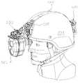
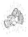
- the helmet mount assembly 530which contains a pivoting assembly for moving between an operational position and a stowed position, wherein the pivoting assembly is similar to the pivoting assembly of the helmet mounting system described in U.S. patent application Ser. No. 12/951,969 filed on Nov. 22, 2010. The aforementioned application is incorporated herein by reference in its entirety.
- the helmet mount assembly 530includes a rear plate 502 that interfaces with the connection bracket 504 .
- the connection bracket 504contains guide rails 602 , a first opening, e.g., defined by lower groove lip 592 , and a second opening, e.g., defined by upper groove lip 596 .
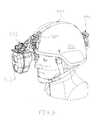
- the pivoting carriage assembly 532is manually pivotable relative to the sliding plate assembly 510 about the pivot pin 646 .
- the carriage assembly 532may be pivoted downward until the protrusions 648 engage the channel 668 b formed in the inner wall of the sleeve 528 .
- the spring washers 664urge the protrusions 648 into the channel 668 b to secure the mount in the operative deployed position wherein the associated goggle will be positioned in front of the eye(s) of the user.
- the wearerapplies a pivoting force to the goggles.
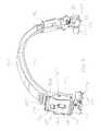
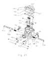
- the bottom of the slide carriage 536engages the left and right sliding arm 544 at rails 556 .
- the slide arm 544has a locking mechanism attached on its underside and the locking mechanism has a lever 558 , a lock shim 694 , a bushing 696 , and a pin or drawbar 698 .
- the usermay adjust the horizontal position of the attached optical device 512 in the left and right direction by releasing the lever 558 .
- the userpulls down the lever 558 to release the locking mechanism and in turn the lever 558 pulls pin 698 from channel 700 thereby releasing lock shim 694 from engagement with the bottom of sliding arm 544 .
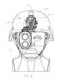
- the helmet interface assembly 546also includes a mounting shoe receiver 564 and a lever 562 .
- the mounting shoe receiver 564has a channel 710 for receiving a first interface 712 . Once the first interface 712 is inserted into the channel 710 it is secured to the mounting shoe receiver 564 via fasteners 714 .
- the optical device 512is secured to the mounting shoe receiver 564 the first interface 712 provides power to the optical device 512 through the electrical contacts (not shown) of its mounting shoe (not shown).
- the optical device 512is secured to the interface assembly 546 by releasing the lever 562 , inserting the mating mounting shoe (not shown) of the optical device 512 into the mounting shoe receiver 564 and closing the lever 562 .
- Threaded fastenersare used to secure the mounting shoe assembly 100 to a device via the openings 122 in the top cover, aligned openings 126 in the base 102 and the opening 124 in the base.
- the contacts 106are flat contacts adapted to make electrical contact with a spring contact, such as the contacts 716 on the mounting shoe receptacle 564 , described above. It will be recognized that the assembly 100 could be modified to employ spring contacts instead of flat contacts. It is preferred, however, that the mounting shoe assembly 100 adapted for generally permanent attachment on a night vision device or other device to be powered employ flat contacts to minimize the potential for damage to the contacts.
- the board 104has six contacts 106 .
- the contacts 156are flat contacts adapted to make electrical contact with a spring contact, such as the contacts 716 on the mounting shoe receptacle 564 , described above. It will be recognized that the assembly 150 could be modified to employ spring contacts instead of flat contacts. It is preferred, however, that the mounting shoe assembly 150 adapted for generally permanent attachment on a night vision device or other device to be powered employ flat contacts to minimize the potential for damage to the contacts.
- the board 154has six contacts 156 . This allows for redundant power contacts, e.g., two positive, two negative, as well as two data or signal contacts. By providing multiple positive and negative power terminals, power can still be supplied to the device, even where on of the contacts is damaged or otherwise not making electrical contact with the aligned contact on the mounting shoe receptacle.
- the device to be poweredmay be an optical device, such as, a monocular or binoculars, a monocular or binocular night vision goggle device, eNVG devices, helmet mounted display screens, head-up displays or any other helmet mounted optical, electro-optical, and/or viewing devices, attached to a helmet mounting system.
- an optical devicesuch as, a monocular or binoculars, a monocular or binocular night vision goggle device, eNVG devices, helmet mounted display screens, head-up displays or any other helmet mounted optical, electro-optical, and/or viewing devices, attached to a helmet mounting system.
- the power supply hereincan be used to provide electrical power to all manner of electrical and electronic devices.
Landscapes
- Helmets And Other Head Coverings (AREA)
Abstract
Description
Claims (22)
Priority Applications (1)
| Application Number | Priority Date | Filing Date | Title |
|---|---|---|---|
| US13/019,889US8984665B2 (en) | 2010-02-02 | 2011-02-02 | Helmet mounting system and mounting shoe interface |
Applications Claiming Priority (3)
| Application Number | Priority Date | Filing Date | Title |
|---|---|---|---|
| US30077010P | 2010-02-02 | 2010-02-02 | |
| US35108410P | 2010-06-03 | 2010-06-03 | |
| US13/019,889US8984665B2 (en) | 2010-02-02 | 2011-02-02 | Helmet mounting system and mounting shoe interface |
Publications (2)
| Publication Number | Publication Date |
|---|---|
| US20110239354A1 US20110239354A1 (en) | 2011-10-06 |
| US8984665B2true US8984665B2 (en) | 2015-03-24 |
Family
ID=44707886
Family Applications (1)
| Application Number | Title | Priority Date | Filing Date |
|---|---|---|---|
| US13/019,889Active2033-06-17US8984665B2 (en) | 2010-02-02 | 2011-02-02 | Helmet mounting system and mounting shoe interface |
Country Status (1)
| Country | Link |
|---|---|
| US (1) | US8984665B2 (en) |
Cited By (27)
| Publication number | Priority date | Publication date | Assignee | Title |
|---|---|---|---|---|
| US20150157079A1 (en)* | 2012-06-13 | 2015-06-11 | Savox Communications Oy Ab (Ltd) | Wearable chassis for a helmet |
| US9146394B1 (en)* | 2012-12-13 | 2015-09-29 | Optics 1, Inc. | Clip-on eye piece system for handheld and device-mounted digital imagers |
| CN106225573A (en)* | 2016-09-27 | 2016-12-14 | 星际控股集团有限公司 | The bulletproof halmet guide rail of a kind of ready-package connects seat |
| US20170322481A1 (en)* | 2014-11-21 | 2017-11-09 | Tormaxx Gmbh | Holding element for a camera and camera arrangement, holding element and a helmet |
| CN107736677A (en)* | 2017-11-17 | 2018-02-27 | 江西联创电声有限公司 | Helmet mounting bracket and helmet |
| US20180231404A1 (en)* | 2017-02-13 | 2018-08-16 | Lockheed Martin Corporation | Sensor system |
| US20190011702A1 (en)* | 2017-07-06 | 2019-01-10 | RAVR Incorporation Ltd. | Helmet-Mounted Visualization Device Without Parallax and its Operation Method |
| USD900407S1 (en)* | 2020-05-22 | 2020-10-27 | Gentex Corporation | Helmet accessory mounting system |
| US20210239962A1 (en)* | 2020-01-18 | 2021-08-05 | TNVC, Inc. | Modular binocular night vision device |
| US11122698B2 (en) | 2018-11-06 | 2021-09-14 | N2 Imaging Systems, LLC | Low stress electronic board retainers and assemblies |
| US11143838B2 (en) | 2019-01-08 | 2021-10-12 | N2 Imaging Systems, LLC | Optical element retainers |
| US11229252B2 (en) | 2017-03-13 | 2022-01-25 | Gentex Corporation | Helmet mounted shroud |
| US11339919B2 (en)* | 2019-07-23 | 2022-05-24 | Valeda Company, Llc | Remote release assembly for a surface mount |
| US11360309B2 (en) | 2018-06-14 | 2022-06-14 | Wilcox Industries Corp. | High speed hot shoe |
| US11382375B2 (en)* | 2017-03-13 | 2022-07-12 | Gentex Corporation | Modular shroud |
| US20220408869A1 (en)* | 2019-05-22 | 2022-12-29 | Gentex Corporation | Helmet Accessory Mounting System |
| US11612207B2 (en) | 2018-01-08 | 2023-03-28 | Wilcox Industries Corp. | Helmet with integrated sensors |
| US12068600B2 (en) | 2015-11-20 | 2024-08-20 | Galvion Soldier Power, Llc | Power manager with reconfigurable power converting circuits |
| US12119642B2 (en) | 2015-11-20 | 2024-10-15 | Galvion Soldier Power, Llc | Power manager with reconfigurable power converting circuits |
| US12155263B2 (en) | 2021-08-06 | 2024-11-26 | Galvion Ltd. | Helmet-mounted power system |
| USD1062615S1 (en) | 2021-12-21 | 2025-02-18 | Galvion Soldier Power, Llc | Power pack |
| US12253665B2 (en) | 2021-09-24 | 2025-03-18 | Swift Universal Optical Systems Llc | Mounting systems suitable for mounting vision systems |
| US12268269B2 (en) | 2021-05-12 | 2025-04-08 | Galvion Incorporated | System for forming a deep drawn helmet |
| US12285069B2 (en) | 2022-11-23 | 2025-04-29 | Wilcox Industries Corp. | Helmet accessory system |
| US12326707B2 (en) | 2022-05-16 | 2025-06-10 | Galvion Ltd. | Method and system of providing a uniform messaging platform in a heterogeneous environment |
| US12342894B2 (en) | 2022-11-15 | 2025-07-01 | Wilcox Industries Corp. | Reclining helmet mount apparatus |
| US12408718B2 (en) | 2023-07-07 | 2025-09-09 | Wilcox Industries Corp. | Powered helmet accessory rail with slot interface |
Families Citing this family (90)
| Publication number | Priority date | Publication date | Assignee | Title |
|---|---|---|---|---|
| US8656622B2 (en) | 2007-10-11 | 2014-02-25 | Ashbury International Group, Inc. | Tactical firearm systems and methods of manufacturing same |
| US10215529B2 (en)* | 2009-01-16 | 2019-02-26 | Prototype Productions Incorporated Ventures Two, Llc | Accessory mount for rifle accessory rail, communication, and power transfer system—accessory attachment |
| GB2539107B (en)* | 2009-06-01 | 2017-04-05 | Wilcox Ind Corp | Helmet mount for viewing device |
| US20110099695A1 (en)* | 2009-11-04 | 2011-05-05 | David John Siviter | Helmet Bracket System |
| US8739313B2 (en) | 2009-11-20 | 2014-06-03 | Wilcox Industries Corp. | Helmet mounting systems |
| US10337834B2 (en) | 2010-01-15 | 2019-07-02 | Colt Canada Ip Holding Partnership | Networked battle system or firearm |
| US10477618B2 (en) | 2010-01-15 | 2019-11-12 | Colt Canada Ip Holding Partnership | Networked battle system or firearm |
| US10470010B2 (en) | 2010-01-15 | 2019-11-05 | Colt Canada Ip Holding Partnership | Networked battle system or firearm |
| US10477619B2 (en) | 2010-01-15 | 2019-11-12 | Colt Canada Ip Holding Partnership | Networked battle system or firearm |
| US9823043B2 (en)* | 2010-01-15 | 2017-11-21 | Colt Canada Ip Holding Partnership | Rail for inductively powering firearm accessories |
| US9921028B2 (en)* | 2010-01-15 | 2018-03-20 | Colt Canada Ip Holding Partnership | Apparatus and method for powering and networking a rail of a firearm |
| US8984665B2 (en)* | 2010-02-02 | 2015-03-24 | Wilcox Industries Corp. | Helmet mounting system and mounting shoe interface |
| DK3165868T3 (en) | 2011-02-15 | 2018-11-26 | Colt Canada Ip Holding Partnership | Apparatus and method for inductive power supply and network connection of a firearm's rail |
| US8810482B2 (en) | 2011-06-29 | 2014-08-19 | Recon Instruments Inc. | Modular heads-up display systems |
| US8813270B2 (en)* | 2011-07-26 | 2014-08-26 | Vladimiro Pizzi | Helmet with flush aligned shield when closed |
| US9116355B2 (en)* | 2011-09-30 | 2015-08-25 | Wilcox Industries Corp. | Monocular/binocular bridge for viewing device and helmet mount employing same |
| US8908389B2 (en)* | 2011-10-07 | 2014-12-09 | Wilcox Industries Corp. | Power distribution system and helmet and method employing the same |
| US20130104297A1 (en)* | 2011-11-01 | 2013-05-02 | Brandon James Silva | Digital Device Screen Mount for a Helmet |
| US9705605B2 (en) | 2012-02-09 | 2017-07-11 | N2 Imaging Systems, LLC | Intrapersonal data communication system |
| US9042736B2 (en) | 2012-02-09 | 2015-05-26 | N2 Imaging Systems, LLC | Intrapersonal data communication systems |
| WO2013192070A1 (en) | 2012-06-18 | 2013-12-27 | Gentex Corporation | Helmet cover assembly having at least one mounting device |
| US10051908B2 (en)* | 2012-06-28 | 2018-08-21 | Revision Military S.A.R.L. | Helmet-mounted display |
| US9433252B2 (en)* | 2012-07-31 | 2016-09-06 | Revision Military S.Ar.L. | Helmet accessory attachment system |
| US10492555B2 (en)* | 2012-07-31 | 2019-12-03 | Rm Soldier Systems, Ltd. | Helmet mounting system |
| CA2881982C (en)* | 2012-08-16 | 2020-10-13 | Colt Canada Corporation | Apparatus and method for powering and networking a rail of a firearm |
| US8701212B2 (en)* | 2012-09-26 | 2014-04-22 | 3M Innovative Properties Company | Elongated guide, and visor removably mountable thereto |
| CN103791215B (en)* | 2012-10-30 | 2015-12-23 | 北京航天长峰科技工业集团有限公司 | Fixing and the regulation structure of monocular display on a kind of helmet |
| CN103791779A (en)* | 2012-10-30 | 2014-05-14 | 北京航天长峰科技工业集团有限公司 | Electrified bulletproof helmet |
| US9167859B2 (en)* | 2013-03-13 | 2015-10-27 | Exelis, Inc. | System for mounting a helmet-mounted device to a helmet |
| US9033726B2 (en) | 2013-03-13 | 2015-05-19 | Exelis, Inc. | Systems for establishing electrical interconnections for helmet-mounted devices |
| USD700928S1 (en)* | 2013-03-15 | 2014-03-11 | Bae Systems Information And Electronic Systems Integration Inc. | Goggles and thermal sensor |
| US10162168B2 (en)* | 2013-05-03 | 2018-12-25 | Wilcox Industries Corp. | Binocular bridge for thermal viewing device |
| DK3013168T3 (en) | 2013-06-27 | 2020-02-17 | Galvion Ltd | HELMET MOUNTING SYSTEM |
| US9709792B2 (en) | 2013-06-28 | 2017-07-18 | Wilcox Industries Corp. | Helmet mount with integral binocular bridge |
| US9578916B2 (en) | 2014-02-11 | 2017-02-28 | 3M Innovative Properties Company | Appliance mounting device and system for head gear |
| US10007329B1 (en) | 2014-02-11 | 2018-06-26 | Leap Motion, Inc. | Drift cancelation for portable object detection and tracking |
| AU2015201313A1 (en)* | 2014-03-14 | 2015-10-01 | Wilcox Industries Corp. | Modular camera system |
| US10021931B2 (en) | 2014-04-02 | 2018-07-17 | Sopro Mounts Inc. | Helmet-chin mount for accessories, including cameras |
| US9754167B1 (en) | 2014-04-17 | 2017-09-05 | Leap Motion, Inc. | Safety for wearable virtual reality devices via object detection and tracking |
| US20150320189A1 (en)* | 2014-05-09 | 2015-11-12 | Leap Motion, Inc. | Adapter for Attaching a Motion Capture Device to a Head Mounted Display |
| US9741169B1 (en) | 2014-05-20 | 2017-08-22 | Leap Motion, Inc. | Wearable augmented reality devices with object detection and tracking |
| US9646201B1 (en) | 2014-06-05 | 2017-05-09 | Leap Motion, Inc. | Three dimensional (3D) modeling of a complex control object |
| US10383387B2 (en)* | 2014-06-10 | 2019-08-20 | Revision Military S.A.R.L. | Apparatus and methods for securing accessories to a helmet |
| US10007350B1 (en) | 2014-06-26 | 2018-06-26 | Leap Motion, Inc. | Integrated gestural interaction and multi-user collaboration in immersive virtual reality environments |
| CN204480228U (en) | 2014-08-08 | 2015-07-15 | 厉动公司 | motion sensing and imaging device |
| US10100871B2 (en) | 2014-10-30 | 2018-10-16 | Knightvision, Lllp | Bridge mount device and system |
| US10656720B1 (en) | 2015-01-16 | 2020-05-19 | Ultrahaptics IP Two Limited | Mode switching for integrated gestural interaction and multi-user collaboration in immersive virtual reality environments |
| US10455881B2 (en)* | 2015-04-21 | 2019-10-29 | Cadequip, Inc. | Adjustable headgear mount system |
| US11771164B2 (en) | 2015-05-18 | 2023-10-03 | Arcachon Holdings Llc | System, method, and apparatus for synchronizing local flashing in a marker system |
| US11047984B2 (en)* | 2015-05-18 | 2021-06-29 | Arcachon Holdings Llc | System, method, and apparatus for synchronizing local flashing in a marker system |
| US9958667B2 (en) | 2015-06-17 | 2018-05-01 | Robert J. McCreight, Jr. | Apparatus, system, and method for a mounting shoe with locking projection |
| JP2017049762A (en)* | 2015-09-01 | 2017-03-09 | 株式会社東芝 | System and method |
| CN105138999B (en)* | 2015-09-16 | 2019-03-15 | 三峡大学 | Shadow-based monocular positioning device and method for night objects |
| USD757154S1 (en)* | 2015-10-27 | 2016-05-24 | Yoolod Inc. | Wearable light sensing device |
| US10113837B2 (en) | 2015-11-03 | 2018-10-30 | N2 Imaging Systems, LLC | Non-contact optical connections for firearm accessories |
| US9943127B2 (en) | 2015-11-30 | 2018-04-17 | Revision Military S.A.R.L. | Adjustable connector for a helmet accessory |
| EP3417338B1 (en)* | 2016-02-15 | 2024-09-25 | Advanced Material Engineering Pte Ltd | Modular add-on augmented reality head-up display, interfaces and controls |
| US10959473B2 (en)* | 2017-01-10 | 2021-03-30 | Hmount Ltd | Plastic helmet mounting assembly |
| US20180192726A1 (en)* | 2017-01-10 | 2018-07-12 | Hmount Ltd | Plastic helmet mounting assembly |
| IL250044B (en)* | 2017-01-10 | 2019-05-30 | Shlomo Chen Itay | Plastic helmet mounting assembly |
| ES2844400T3 (en)* | 2017-02-17 | 2021-07-22 | Savox Communications Oy Ab Ltd | Adaptive mounting system for mounting one or more accessory devices on a helmet |
| CA3054446C (en) | 2017-03-13 | 2022-03-15 | Gentex Corporation | Mounting rail assembly |
| US10288864B2 (en)* | 2017-04-28 | 2019-05-14 | Norotos, Inc. | Night vision goggle adapter |
| CA3063839A1 (en)* | 2017-05-15 | 2018-11-22 | T-Worx Holdings, LLC | Power system for a firearm |
| TWI626899B (en)* | 2017-06-14 | 2018-06-21 | Zhang le yan | helmet |
| US10753709B2 (en) | 2018-05-17 | 2020-08-25 | Sensors Unlimited, Inc. | Tactical rails, tactical rail systems, and firearm assemblies having tactical rails |
| US11079202B2 (en) | 2018-07-07 | 2021-08-03 | Sensors Unlimited, Inc. | Boresighting peripherals to digital weapon sights |
| US10645348B2 (en) | 2018-07-07 | 2020-05-05 | Sensors Unlimited, Inc. | Data communication between image sensors and image displays |
| US10742913B2 (en) | 2018-08-08 | 2020-08-11 | N2 Imaging Systems, LLC | Shutterless calibration |
| AU2020286175A1 (en)* | 2018-09-04 | 2021-01-07 | Designworks Defence Systems Pty Ltd | Operational mode sensing switch system and multi-orientated mounting system for a helmet mounted night vision device |
| EP3846652A4 (en)* | 2018-09-04 | 2022-09-07 | Designworks Defence Systems Pty Ltd | OPERATING MODE SENSING SWITCH SYSTEM AND MULTI-ORIENTED MOUNTING SYSTEM FOR A HELMET-MOUNTED NIGHT VISION DEVICE |
| US10921578B2 (en) | 2018-09-07 | 2021-02-16 | Sensors Unlimited, Inc. | Eyecups for optics |
| US10801813B2 (en) | 2018-11-07 | 2020-10-13 | N2 Imaging Systems, LLC | Adjustable-power data rail on a digital weapon sight |
| US10417497B1 (en)* | 2018-11-09 | 2019-09-17 | Qwake Technologies | Cognitive load reducing platform for first responders |
| US11890494B2 (en) | 2018-11-09 | 2024-02-06 | Qwake Technologies, Inc. | Retrofittable mask mount system for cognitive load reducing platform |
| US10896492B2 (en) | 2018-11-09 | 2021-01-19 | Qwake Technologies, Llc | Cognitive load reducing platform having image edge enhancement |
| US10796860B2 (en) | 2018-12-12 | 2020-10-06 | N2 Imaging Systems, LLC | Hermetically sealed over-molded button assembly |
| EP3714721A1 (en)* | 2019-03-28 | 2020-09-30 | Wilcox Industries Corp. | Interface system for a helmet mounting system |
| US20200321730A1 (en)* | 2019-06-21 | 2020-10-08 | Intel Corporation | Small form factor connection mechanism for a card to card connector |
| US11327291B2 (en) | 2019-06-24 | 2022-05-10 | Elbit Systems Of America, Llc | Single actuation goggle positioning mounting assembly |
| US11915376B2 (en) | 2019-08-28 | 2024-02-27 | Qwake Technologies, Inc. | Wearable assisted perception module for navigation and communication in hazardous environments |
| US11054628B2 (en)* | 2019-11-13 | 2021-07-06 | Norotos, Inc. | Adjustable night vision goggle adapter |
| EP3835709A1 (en)* | 2019-12-11 | 2021-06-16 | FN Herstal S.A. | Mounting rail for a firearm |
| IL302958A (en)* | 2020-11-25 | 2023-07-01 | Gentex Corp | Helmet accessories assembly system |
| CN112526758B (en)* | 2021-01-13 | 2024-12-13 | 深圳鑫宏力精密工业有限公司 | A monitoring instrument for head mounted display device and a method of using the same |
| US20220341697A1 (en)* | 2021-04-21 | 2022-10-27 | T-Worx Holdings, LLC | Electrical power source for a firearm |
| GR1010276B (en)* | 2021-08-04 | 2022-08-05 | Norotos, Inc., | Magnetic switch adapter for night vision goggles |
| US11762208B1 (en)* | 2022-03-31 | 2023-09-19 | Lenovo Global Technology (United States) Inc. | Cooling a virtual reality headset |
| US12250361B2 (en)* | 2022-08-18 | 2025-03-11 | Apple Inc. | Optical assemblies for shared experience |
| US20240365911A1 (en)* | 2023-05-01 | 2024-11-07 | Wilcox Industries Corp. | Multi-position helmet mount pivot hinge and helmet mount apparatus employing same |
Citations (43)
| Publication number | Priority date | Publication date | Assignee | Title |
|---|---|---|---|---|
| US4156292A (en) | 1978-05-23 | 1979-05-29 | The United States Of America As Represented By The Secretary Of The Army | Display carrying and protective helmet |
| US4242757A (en) | 1978-01-11 | 1981-01-06 | Nava Pier Luigi | Helmet with tiltable visor |
| US4449787A (en) | 1980-07-22 | 1984-05-22 | International Telephone And Telegraph Corporation | Night vision imaging system adapted for helmet mounting |
| US4577347A (en) | 1984-07-25 | 1986-03-25 | The United States Of America As Represented By The Secretary Of The Air Force | Direct view helmet mounted telescope |
| US4660943A (en) | 1984-12-17 | 1987-04-28 | Gec Avionics Limited | Night vision systems |
| US4689834A (en) | 1984-02-15 | 1987-09-01 | Mccarthy Brian D | Night vision goggle arrangement with automatic release |
| US4901210A (en) | 1987-12-30 | 1990-02-13 | Akira Hanabusa | Detachable rear-mounted light for a motorcycle helmet |
| US4987608A (en) | 1988-06-30 | 1991-01-29 | The United States Of America As Represented By The Secretary Of The Army | Mounting means for use of ground system type goggles as aviators goggle |
| FR2677604A1 (en) | 1991-06-12 | 1992-12-18 | Sextant Avionique | Device for fastening a head equipment item onto a pilot's helmet |
| US5265276A (en) | 1993-02-25 | 1993-11-30 | The United States Of America As Represented By The Secretary Of The Army | Helmet visor adaptor assembly |
| US5367402A (en) | 1992-12-14 | 1994-11-22 | Itt Corporation | Helmet mounted night vision apparatus and method of separation |
| US5408086A (en) | 1993-06-24 | 1995-04-18 | Litton Systems, Inc. | Head-mounted flip-up night vision device with automatic turn-off upon flip-up |
| US5412811A (en) | 1991-10-04 | 1995-05-09 | Carl-Zeiss-Stiftung | Headgear having a holding device for holding an instrument |
| US5416922A (en) | 1993-02-23 | 1995-05-23 | The United States Of America As Represented By The Secretary Of The Navy | Helmet head tracking mounting device |
| US5467479A (en) | 1993-05-07 | 1995-11-21 | Varo Inc. | Night vision goggle mount |
| US5471678A (en) | 1992-07-13 | 1995-12-05 | Litton Systems, Inc. | Flip-up mount for night vision system |
| US5506730A (en) | 1993-09-09 | 1996-04-09 | Litton Systems, Inc. | Flip-up helmet mount for night vision goggle |
| US5535053A (en) | 1994-08-15 | 1996-07-09 | Itt Corporation | Night vision goggle assembly with independant monocular devices |
| US5542627A (en) | 1994-02-17 | 1996-08-06 | Itt Corporation | Quick release coupling apparatus and method for a helmet mounted night vision goggle arrangement |
| US5581806A (en) | 1994-03-08 | 1996-12-10 | Sextant Avionique | Device for the mechanical hooking of a display system to a helmet |
| US5703354A (en) | 1996-02-28 | 1997-12-30 | Litton Systems, Inc. | Binocular night vision device and method of making and using the device |
| USD392071S (en) | 1996-08-06 | 1998-03-10 | Berke Joseph J | Industrial helmet with an extended vision optical element |
| USD402421S (en) | 1996-08-06 | 1998-12-08 | Berke Joseph J | Pair of detachable extended vision optical elements for a helmet |
| US5898472A (en) | 1997-07-08 | 1999-04-27 | Oshikawa; Hidetoshi | Automatic eyewear strap winding device |
| US5914816A (en) | 1997-11-04 | 1999-06-22 | Norotos, Inc. | Helmet mount for night vision goggle |
| US5920371A (en) | 1996-07-12 | 1999-07-06 | Chang; Byung Jin | Versatile headband optical mounting assembly |
| US20020120979A1 (en) | 2001-01-05 | 2002-09-05 | Prendergast Jonathan R. | Helmet mount for night vision device |
| US6462867B2 (en) | 2001-02-16 | 2002-10-08 | Insight Technology, Inc. | Monocular mounting for multi-channel panoramic night vision goggle having an angled mounting shoe |
| US6472776B1 (en) | 2000-03-30 | 2002-10-29 | Norotos, Inc. | Helmet mount for night vision device |
| US6560029B1 (en) | 2001-12-21 | 2003-05-06 | Itt Manufacturing Enterprises, Inc. | Video enhanced night vision goggle |
| US6662370B1 (en) | 2002-01-11 | 2003-12-16 | Itt Manufacturing Enterprises, Inc. | Night vision device helmet mount |
| US6795977B2 (en) | 2000-05-22 | 2004-09-28 | Gilles Basson | Protective helmet and means for connection of an accessory |
| US20050111097A1 (en)* | 2003-11-26 | 2005-05-26 | Iannarelli Thomas M. | Head mounted binoculars/range finder |
| US6957449B2 (en) | 2003-04-04 | 2005-10-25 | Norotos, Inc. | Rotatable helmet mount |
| WO2006065805A2 (en)* | 2004-12-17 | 2006-06-22 | Insight Technology, Inc. | Apparatus for mounting a vision system |
| US7219370B1 (en)* | 2003-10-06 | 2007-05-22 | Wilcox Industries Corp. | Helmet mounting systems |
| US20080170838A1 (en)* | 2007-01-11 | 2008-07-17 | Wilcox Industries Corp. | Head-mounted video recording system |
| US7735159B2 (en) | 2005-06-23 | 2010-06-15 | Norotos, Inc. | Monorail mount for enhanced night vision goggles |
| US20100299814A1 (en)* | 2009-06-01 | 2010-12-02 | Wilcox Industries Corp. | Helmet Mount for Viewing Device |
| US20110145981A1 (en)* | 2009-11-20 | 2011-06-23 | Wilcox Industries Corp. | Helmet Mounting Systems |
| US20110239354A1 (en)* | 2010-02-02 | 2011-10-06 | Wilcox Industries Corp. | Helmet mounting system and mounting shoe interface |
| US8209780B1 (en)* | 2007-10-25 | 2012-07-03 | Wilcox Industries Corp. | Pivoting helmet mount |
| US20130083391A1 (en)* | 2011-09-30 | 2013-04-04 | Wilcox Industries Corp. | Monocular/binocular bridge for viewing device and helmet mount employing same |
- 2011
- 2011-02-02USUS13/019,889patent/US8984665B2/enactiveActive
Patent Citations (47)
| Publication number | Priority date | Publication date | Assignee | Title |
|---|---|---|---|---|
| US4242757A (en) | 1978-01-11 | 1981-01-06 | Nava Pier Luigi | Helmet with tiltable visor |
| US4156292A (en) | 1978-05-23 | 1979-05-29 | The United States Of America As Represented By The Secretary Of The Army | Display carrying and protective helmet |
| US4449787A (en) | 1980-07-22 | 1984-05-22 | International Telephone And Telegraph Corporation | Night vision imaging system adapted for helmet mounting |
| US4689834A (en) | 1984-02-15 | 1987-09-01 | Mccarthy Brian D | Night vision goggle arrangement with automatic release |
| US4577347A (en) | 1984-07-25 | 1986-03-25 | The United States Of America As Represented By The Secretary Of The Air Force | Direct view helmet mounted telescope |
| US4660943A (en) | 1984-12-17 | 1987-04-28 | Gec Avionics Limited | Night vision systems |
| US4901210A (en) | 1987-12-30 | 1990-02-13 | Akira Hanabusa | Detachable rear-mounted light for a motorcycle helmet |
| US4987608A (en) | 1988-06-30 | 1991-01-29 | The United States Of America As Represented By The Secretary Of The Army | Mounting means for use of ground system type goggles as aviators goggle |
| FR2677604A1 (en) | 1991-06-12 | 1992-12-18 | Sextant Avionique | Device for fastening a head equipment item onto a pilot's helmet |
| US5412811A (en) | 1991-10-04 | 1995-05-09 | Carl-Zeiss-Stiftung | Headgear having a holding device for holding an instrument |
| US5471678A (en) | 1992-07-13 | 1995-12-05 | Litton Systems, Inc. | Flip-up mount for night vision system |
| US5367402A (en) | 1992-12-14 | 1994-11-22 | Itt Corporation | Helmet mounted night vision apparatus and method of separation |
| US5416922A (en) | 1993-02-23 | 1995-05-23 | The United States Of America As Represented By The Secretary Of The Navy | Helmet head tracking mounting device |
| US5265276A (en) | 1993-02-25 | 1993-11-30 | The United States Of America As Represented By The Secretary Of The Army | Helmet visor adaptor assembly |
| US5467479A (en) | 1993-05-07 | 1995-11-21 | Varo Inc. | Night vision goggle mount |
| US5408086A (en) | 1993-06-24 | 1995-04-18 | Litton Systems, Inc. | Head-mounted flip-up night vision device with automatic turn-off upon flip-up |
| US5506730A (en) | 1993-09-09 | 1996-04-09 | Litton Systems, Inc. | Flip-up helmet mount for night vision goggle |
| US5542627A (en) | 1994-02-17 | 1996-08-06 | Itt Corporation | Quick release coupling apparatus and method for a helmet mounted night vision goggle arrangement |
| US5581806A (en) | 1994-03-08 | 1996-12-10 | Sextant Avionique | Device for the mechanical hooking of a display system to a helmet |
| US5535053A (en) | 1994-08-15 | 1996-07-09 | Itt Corporation | Night vision goggle assembly with independant monocular devices |
| US5703354A (en) | 1996-02-28 | 1997-12-30 | Litton Systems, Inc. | Binocular night vision device and method of making and using the device |
| US5920371A (en) | 1996-07-12 | 1999-07-06 | Chang; Byung Jin | Versatile headband optical mounting assembly |
| USD402421S (en) | 1996-08-06 | 1998-12-08 | Berke Joseph J | Pair of detachable extended vision optical elements for a helmet |
| USD392071S (en) | 1996-08-06 | 1998-03-10 | Berke Joseph J | Industrial helmet with an extended vision optical element |
| US5898472A (en) | 1997-07-08 | 1999-04-27 | Oshikawa; Hidetoshi | Automatic eyewear strap winding device |
| US5914816A (en) | 1997-11-04 | 1999-06-22 | Norotos, Inc. | Helmet mount for night vision goggle |
| US6472776B1 (en) | 2000-03-30 | 2002-10-29 | Norotos, Inc. | Helmet mount for night vision device |
| US6795977B2 (en) | 2000-05-22 | 2004-09-28 | Gilles Basson | Protective helmet and means for connection of an accessory |
| US6457179B1 (en) | 2001-01-05 | 2002-10-01 | Norotos, Inc. | Helmet mount for night vision device |
| US20020120979A1 (en) | 2001-01-05 | 2002-09-05 | Prendergast Jonathan R. | Helmet mount for night vision device |
| US6462867B2 (en) | 2001-02-16 | 2002-10-08 | Insight Technology, Inc. | Monocular mounting for multi-channel panoramic night vision goggle having an angled mounting shoe |
| US6560029B1 (en) | 2001-12-21 | 2003-05-06 | Itt Manufacturing Enterprises, Inc. | Video enhanced night vision goggle |
| US6662370B1 (en) | 2002-01-11 | 2003-12-16 | Itt Manufacturing Enterprises, Inc. | Night vision device helmet mount |
| US6957449B2 (en) | 2003-04-04 | 2005-10-25 | Norotos, Inc. | Rotatable helmet mount |
| US20070214551A1 (en)* | 2003-10-06 | 2007-09-20 | Wilcox Industries Corp. | Helmet mounting systems |
| US7219370B1 (en)* | 2003-10-06 | 2007-05-22 | Wilcox Industries Corp. | Helmet mounting systems |
| US20050111097A1 (en)* | 2003-11-26 | 2005-05-26 | Iannarelli Thomas M. | Head mounted binoculars/range finder |
| WO2006065805A2 (en)* | 2004-12-17 | 2006-06-22 | Insight Technology, Inc. | Apparatus for mounting a vision system |
| US20080263752A1 (en)* | 2004-12-17 | 2008-10-30 | Insight Technology, Inc. | Method and Apparatus for Mounting a Vision System |
| US7735159B2 (en) | 2005-06-23 | 2010-06-15 | Norotos, Inc. | Monorail mount for enhanced night vision goggles |
| US20080170838A1 (en)* | 2007-01-11 | 2008-07-17 | Wilcox Industries Corp. | Head-mounted video recording system |
| US8209780B1 (en)* | 2007-10-25 | 2012-07-03 | Wilcox Industries Corp. | Pivoting helmet mount |
| US20100299814A1 (en)* | 2009-06-01 | 2010-12-02 | Wilcox Industries Corp. | Helmet Mount for Viewing Device |
| GB2470831A (en) | 2009-06-01 | 2010-12-08 | Marc J Celona | Helmet mount for viewing device |
| US20110145981A1 (en)* | 2009-11-20 | 2011-06-23 | Wilcox Industries Corp. | Helmet Mounting Systems |
| US20110239354A1 (en)* | 2010-02-02 | 2011-10-06 | Wilcox Industries Corp. | Helmet mounting system and mounting shoe interface |
| US20130083391A1 (en)* | 2011-09-30 | 2013-04-04 | Wilcox Industries Corp. | Monocular/binocular bridge for viewing device and helmet mount employing same |
Non-Patent Citations (4)
| Title |
|---|
| U.S. Appl. No. 12/117,704, filed May 8, 2008. |
| U.S. Appl. No. 12/259,010, filed Oct. 27, 2010. |
| U.S. Appl. No. 12/759,435, filed Apr. 13, 2010. |
| U.S. Appl. No. 12/951,969, filed Nov. 22, 2010. |
Cited By (38)
| Publication number | Priority date | Publication date | Assignee | Title |
|---|---|---|---|---|
| US9788587B2 (en)* | 2012-06-13 | 2017-10-17 | Savox Communications Oy Ab (Ltd) | Helmet system with a wearable chassis |
| US20150157079A1 (en)* | 2012-06-13 | 2015-06-11 | Savox Communications Oy Ab (Ltd) | Wearable chassis for a helmet |
| US9146394B1 (en)* | 2012-12-13 | 2015-09-29 | Optics 1, Inc. | Clip-on eye piece system for handheld and device-mounted digital imagers |
| US20170322481A1 (en)* | 2014-11-21 | 2017-11-09 | Tormaxx Gmbh | Holding element for a camera and camera arrangement, holding element and a helmet |
| US12119642B2 (en) | 2015-11-20 | 2024-10-15 | Galvion Soldier Power, Llc | Power manager with reconfigurable power converting circuits |
| US12068600B2 (en) | 2015-11-20 | 2024-08-20 | Galvion Soldier Power, Llc | Power manager with reconfigurable power converting circuits |
| CN106225573A (en)* | 2016-09-27 | 2016-12-14 | 星际控股集团有限公司 | The bulletproof halmet guide rail of a kind of ready-package connects seat |
| US11287292B2 (en)* | 2017-02-13 | 2022-03-29 | Lockheed Martin Corporation | Sensor system |
| US20180231404A1 (en)* | 2017-02-13 | 2018-08-16 | Lockheed Martin Corporation | Sensor system |
| US11382375B2 (en)* | 2017-03-13 | 2022-07-12 | Gentex Corporation | Modular shroud |
| US11229252B2 (en) | 2017-03-13 | 2022-01-25 | Gentex Corporation | Helmet mounted shroud |
| US20190011702A1 (en)* | 2017-07-06 | 2019-01-10 | RAVR Incorporation Ltd. | Helmet-Mounted Visualization Device Without Parallax and its Operation Method |
| CN107736677A (en)* | 2017-11-17 | 2018-02-27 | 江西联创电声有限公司 | Helmet mounting bracket and helmet |
| US11612207B2 (en) | 2018-01-08 | 2023-03-28 | Wilcox Industries Corp. | Helmet with integrated sensors |
| US11360309B2 (en) | 2018-06-14 | 2022-06-14 | Wilcox Industries Corp. | High speed hot shoe |
| US11122698B2 (en) | 2018-11-06 | 2021-09-14 | N2 Imaging Systems, LLC | Low stress electronic board retainers and assemblies |
| US11143838B2 (en) | 2019-01-08 | 2021-10-12 | N2 Imaging Systems, LLC | Optical element retainers |
| US20240389704A1 (en)* | 2019-05-22 | 2024-11-28 | Gentex Corporation | Helmet Accessory Mounting System |
| US20220408869A1 (en)* | 2019-05-22 | 2022-12-29 | Gentex Corporation | Helmet Accessory Mounting System |
| US11930879B2 (en)* | 2019-05-22 | 2024-03-19 | Gentex Corporation | Helmet accessory mounting system |
| US11339919B2 (en)* | 2019-07-23 | 2022-05-24 | Valeda Company, Llc | Remote release assembly for a surface mount |
| US11821575B2 (en) | 2019-07-23 | 2023-11-21 | Valeda Company, Llc | Remote release assembly for a surface mount |
| US11614612B2 (en)* | 2020-01-18 | 2023-03-28 | TNVC, Inc. | Modular binocular night vision device |
| US20230236410A1 (en)* | 2020-01-18 | 2023-07-27 | TNVC, Inc. | Modular binocular night vision device |
| US20210239962A1 (en)* | 2020-01-18 | 2021-08-05 | TNVC, Inc. | Modular binocular night vision device |
| USD1003526S1 (en) | 2020-05-22 | 2023-10-31 | Gentex Corporation | Power supply attachment surface node |
| USD974670S1 (en) | 2020-05-22 | 2023-01-03 | Gentex Corporation | Helmet accessory mounting system |
| USD900407S1 (en)* | 2020-05-22 | 2020-10-27 | Gentex Corporation | Helmet accessory mounting system |
| USD955661S1 (en) | 2020-05-22 | 2022-06-21 | Gentex Corporation | Mounting rail |
| USD922693S1 (en) | 2020-05-22 | 2021-06-15 | Gentex Corporation | Mounting rail node |
| US12268269B2 (en) | 2021-05-12 | 2025-04-08 | Galvion Incorporated | System for forming a deep drawn helmet |
| US12155263B2 (en) | 2021-08-06 | 2024-11-26 | Galvion Ltd. | Helmet-mounted power system |
| US12253665B2 (en) | 2021-09-24 | 2025-03-18 | Swift Universal Optical Systems Llc | Mounting systems suitable for mounting vision systems |
| USD1062615S1 (en) | 2021-12-21 | 2025-02-18 | Galvion Soldier Power, Llc | Power pack |
| US12326707B2 (en) | 2022-05-16 | 2025-06-10 | Galvion Ltd. | Method and system of providing a uniform messaging platform in a heterogeneous environment |
| US12342894B2 (en) | 2022-11-15 | 2025-07-01 | Wilcox Industries Corp. | Reclining helmet mount apparatus |
| US12285069B2 (en) | 2022-11-23 | 2025-04-29 | Wilcox Industries Corp. | Helmet accessory system |
| US12408718B2 (en) | 2023-07-07 | 2025-09-09 | Wilcox Industries Corp. | Powered helmet accessory rail with slot interface |
Also Published As
| Publication number | Publication date |
|---|---|
| US20110239354A1 (en) | 2011-10-06 |
Similar Documents
| Publication | Publication Date | Title |
|---|---|---|
| US8984665B2 (en) | Helmet mounting system and mounting shoe interface | |
| US10004289B2 (en) | Helmet mounting systems | |
| US7963426B2 (en) | Receptacle which can be fixed to a head covering and is intended for attachments for sighting devices | |
| US12124154B2 (en) | Extendible L-plate for camera equipment | |
| US12317431B2 (en) | Mounting system, devices, methods and uses thereof | |
| US9203063B2 (en) | Battery box and mounting shoe interface | |
| AU2014202000B2 (en) | Binocular bridge for thermal viewing device | |
| AU2013242851B2 (en) | Helmet mount with integral binocular bridge | |
| JP2811921B2 (en) | Camera mounting structure in camera waterproof case | |
| US10051908B2 (en) | Helmet-mounted display | |
| US8471917B2 (en) | Night vision camera mount quick disconnect | |
| US20080263752A1 (en) | Method and Apparatus for Mounting a Vision System | |
| US9781963B1 (en) | Helmet mount for viewing device | |
| WO2007087019A2 (en) | Headgear light | |
| US12342894B2 (en) | Reclining helmet mount apparatus | |
| US20090135479A1 (en) | Universal Mount for Night Vision Goggles | |
| US5306174A (en) | Connecting device for easy connection of separate casings for electric apparatus | |
| JP3832489B2 (en) | Battery pack, camera accessories | |
| JPH0670209A (en) | Adaptor for attachment of camera accessary | |
| US20240215674A1 (en) | Helmet mount for powered device | |
| WO2025117803A1 (en) | Battery pack | |
| KR200146057Y1 (en) | An attachable/detachable camcorder | |
| GB2514481A (en) | Binocular bridge for thermal viewing device | |
| JPH021691A (en) | Video camera |
Legal Events
| Date | Code | Title | Description |
|---|---|---|---|
| AS | Assignment | Owner name:WILCOX INDUSTRIES CORP., NEW HAMPSHIRE Free format text:ASSIGNMENT OF ASSIGNORS INTEREST;ASSIGNORS:CELONA, MARC J.;GOUPIL, DOMINIC R.;LEMIRE, GARY M.;AND OTHERS;REEL/FRAME:028653/0808 Effective date:20120726 | |
| STCF | Information on status: patent grant | Free format text:PATENTED CASE | |
| AS | Assignment | Owner name:PEOPLE'S UNITED BANK, NATIONAL ASSOCIATION, NEW HAMPSHIRE Free format text:SECURITY INTEREST;ASSIGNOR:WILCOX INDUSTRIES CORP.;REEL/FRAME:044850/0152 Effective date:20171212 Owner name:PEOPLE'S UNITED BANK, NATIONAL ASSOCIATION, NEW HA Free format text:SECURITY INTEREST;ASSIGNOR:WILCOX INDUSTRIES CORP.;REEL/FRAME:044850/0152 Effective date:20171212 | |
| AS | Assignment | Owner name:PEOPLE'S UNITED BANK, NATIONAL ASSOCIATION, NEW HAMPSHIRE Free format text:SECURITY INTEREST;ASSIGNOR:WILCOX INDUSTRIES CORP.;REEL/FRAME:045949/0608 Effective date:20180116 Owner name:PEOPLE'S UNITED BANK, NATIONAL ASSOCIATION, NEW HA Free format text:SECURITY INTEREST;ASSIGNOR:WILCOX INDUSTRIES CORP.;REEL/FRAME:045949/0608 Effective date:20180116 | |
| MAFP | Maintenance fee payment | Free format text:PAYMENT OF MAINTENANCE FEE, 4TH YR, SMALL ENTITY (ORIGINAL EVENT CODE: M2551) Year of fee payment:4 | |
| AS | Assignment | Owner name:PEOPLE'S UNITED BANK, NATIONAL ASSOCIATION, NEW HAMPSHIRE Free format text:SECURITY INTEREST;ASSIGNORS:WILCOX INDUSTRIES CORP.;TEETZEL, JAMES W.;REEL/FRAME:058672/0318 Effective date:20211228 | |
| MAFP | Maintenance fee payment | Free format text:PAYMENT OF MAINTENANCE FEE, 8TH YR, SMALL ENTITY (ORIGINAL EVENT CODE: M2552); ENTITY STATUS OF PATENT OWNER: SMALL ENTITY Year of fee payment:8 |