US8983623B2 - Inductive element for providing MRI compatibility in an implantable medical device lead - Google Patents
Inductive element for providing MRI compatibility in an implantable medical device leadDownload PDFInfo
- Publication number
- US8983623B2 US8983623B2US14/056,746US201314056746AUS8983623B2US 8983623 B2US8983623 B2US 8983623B2US 201314056746 AUS201314056746 AUS 201314056746AUS 8983623 B2US8983623 B2US 8983623B2
- Authority
- US
- United States
- Prior art keywords
- lead
- connector
- inductive element
- conductor
- coil
- Prior art date
- Legal status (The legal status is an assumption and is not a legal conclusion. Google has not performed a legal analysis and makes no representation as to the accuracy of the status listed.)
- Active
Links
- 230000001939inductive effectEffects0.000titleclaimsabstractdescription112
- 239000004020conductorSubstances0.000claimsabstractdescription56
- 238000004804windingMethods0.000claimsdescription51
- 230000001131transforming effectEffects0.000claimsdescription2
- 238000002595magnetic resonance imagingMethods0.000description17
- 229920000295expanded polytetrafluoroethylenePolymers0.000description5
- -1polytetrafluoroethylenePolymers0.000description5
- 239000004696Poly ether ether ketoneSubstances0.000description4
- 239000000560biocompatible materialSubstances0.000description4
- 238000012986modificationMethods0.000description4
- 230000004048modificationEffects0.000description4
- 229920002530polyetherether ketonePolymers0.000description4
- 229920001343polytetrafluoroethylenePolymers0.000description4
- 239000004810polytetrafluoroethyleneSubstances0.000description4
- 239000004812Fluorinated ethylene propyleneSubstances0.000description3
- 238000010438heat treatmentMethods0.000description3
- 238000003780insertionMethods0.000description3
- 230000037431insertionEffects0.000description3
- 239000000463materialSubstances0.000description3
- 238000000034methodMethods0.000description3
- 229920009441perflouroethylene propylenePolymers0.000description3
- BASFCYQUMIYNBI-UHFFFAOYSA-NplatinumChemical compound[Pt]BASFCYQUMIYNBI-UHFFFAOYSA-N0.000description3
- 229920000139polyethylene terephthalatePolymers0.000description3
- 239000005020polyethylene terephthalateSubstances0.000description3
- 229920000642polymerPolymers0.000description3
- 229920002635polyurethanePolymers0.000description3
- 239000004814polyurethaneSubstances0.000description3
- 230000002792vascularEffects0.000description3
- 239000004952PolyamideSubstances0.000description2
- 239000004642PolyimideSubstances0.000description2
- 229920003235aromatic polyamidePolymers0.000description2
- 210000003129brachiocephalic veinAnatomy0.000description2
- 230000000747cardiac effectEffects0.000description2
- 230000000694effectsEffects0.000description2
- 239000010931goldSubstances0.000description2
- 238000003384imaging methodMethods0.000description2
- 238000002513implantationMethods0.000description2
- 238000009413insulationMethods0.000description2
- 230000007246mechanismEffects0.000description2
- 229920002647polyamidePolymers0.000description2
- 229920001721polyimidePolymers0.000description2
- 229920001296polysiloxanePolymers0.000description2
- 230000004044responseEffects0.000description2
- 210000001321subclavian veinAnatomy0.000description2
- 229920002994synthetic fiberPolymers0.000description2
- 239000012209synthetic fiberSubstances0.000description2
- 239000010936titaniumSubstances0.000description2
- 239000004593EpoxySubstances0.000description1
- VGGSQFUCUMXWEO-UHFFFAOYSA-NEtheneChemical compoundC=CVGGSQFUCUMXWEO-UHFFFAOYSA-N0.000description1
- 239000005977EthyleneSubstances0.000description1
- 238000005481NMR spectroscopyMethods0.000description1
- 239000004677NylonSubstances0.000description1
- BQCADISMDOOEFD-UHFFFAOYSA-NSilverChemical compound[Ag]BQCADISMDOOEFD-UHFFFAOYSA-N0.000description1
- 239000004809TeflonSubstances0.000description1
- 229920006362Teflon®Polymers0.000description1
- RTAQQCXQSZGOHL-UHFFFAOYSA-NTitaniumChemical compound[Ti]RTAQQCXQSZGOHL-UHFFFAOYSA-N0.000description1
- QXZUUHYBWMWJHK-UHFFFAOYSA-N[Co].[Ni]Chemical compound[Co].[Ni]QXZUUHYBWMWJHK-UHFFFAOYSA-N0.000description1
- 210000001015abdomenAnatomy0.000description1
- 238000007792additionMethods0.000description1
- 229910045601alloyInorganic materials0.000description1
- 239000000956alloySubstances0.000description1
- 210000002048axillary veinAnatomy0.000description1
- 230000008901benefitEffects0.000description1
- 230000015572biosynthetic processEffects0.000description1
- 229920001577copolymerPolymers0.000description1
- 230000008878couplingEffects0.000description1
- 238000010168coupling processMethods0.000description1
- 238000005859coupling reactionMethods0.000description1
- 239000003989dielectric materialSubstances0.000description1
- 230000005672electromagnetic fieldEffects0.000description1
- 230000005670electromagnetic radiationEffects0.000description1
- HQQADJVZYDDRJT-UHFFFAOYSA-Nethene;prop-1-eneChemical groupC=C.CC=CHQQADJVZYDDRJT-UHFFFAOYSA-N0.000description1
- PCHJSUWPFVWCPO-UHFFFAOYSA-NgoldChemical compound[Au]PCHJSUWPFVWCPO-UHFFFAOYSA-N0.000description1
- 229910052737goldInorganic materials0.000description1
- 229910052741iridiumInorganic materials0.000description1
- GKOZUEZYRPOHIO-UHFFFAOYSA-Niridium atomChemical compound[Ir]GKOZUEZYRPOHIO-UHFFFAOYSA-N0.000description1
- 210000005240left ventricleAnatomy0.000description1
- HLXZNVUGXRDIFK-UHFFFAOYSA-Nnickel titaniumChemical compound[Ti].[Ti].[Ti].[Ti].[Ti].[Ti].[Ti].[Ti].[Ti].[Ti].[Ti].[Ni].[Ni].[Ni].[Ni].[Ni].[Ni].[Ni].[Ni].[Ni].[Ni].[Ni].[Ni].[Ni].[Ni]HLXZNVUGXRDIFK-UHFFFAOYSA-N0.000description1
- 229910001000nickel titaniumInorganic materials0.000description1
- 229920001778nylonPolymers0.000description1
- 229910052697platinumInorganic materials0.000description1
- 210000005245right atriumAnatomy0.000description1
- 210000005241right ventricleAnatomy0.000description1
- 229910052709silverInorganic materials0.000description1
- 239000004332silverSubstances0.000description1
- 239000010935stainless steelSubstances0.000description1
- 229910001220stainless steelInorganic materials0.000description1
- 238000007920subcutaneous administrationMethods0.000description1
- 230000001225therapeutic effectEffects0.000description1
- 229910052719titaniumInorganic materials0.000description1
- 210000002620vena cava superiorAnatomy0.000description1
Images


Classifications
- A—HUMAN NECESSITIES
- A61—MEDICAL OR VETERINARY SCIENCE; HYGIENE
- A61N—ELECTROTHERAPY; MAGNETOTHERAPY; RADIATION THERAPY; ULTRASOUND THERAPY
- A61N1/00—Electrotherapy; Circuits therefor
- A61N1/02—Details
- A61N1/08—Arrangements or circuits for monitoring, protecting, controlling or indicating
- A61N1/086—Magnetic resonance imaging [MRI] compatible leads
- A—HUMAN NECESSITIES
- A61—MEDICAL OR VETERINARY SCIENCE; HYGIENE
- A61N—ELECTROTHERAPY; MAGNETOTHERAPY; RADIATION THERAPY; ULTRASOUND THERAPY
- A61N1/00—Electrotherapy; Circuits therefor
- A61N1/02—Details
- A61N1/04—Electrodes
- A61N1/05—Electrodes for implantation or insertion into the body, e.g. heart electrode
- A61N1/0587—Epicardial electrode systems; Endocardial electrodes piercing the pericardium
- A—HUMAN NECESSITIES
- A61—MEDICAL OR VETERINARY SCIENCE; HYGIENE
- A61N—ELECTROTHERAPY; MAGNETOTHERAPY; RADIATION THERAPY; ULTRASOUND THERAPY
- A61N1/00—Electrotherapy; Circuits therefor
- A61N1/02—Details
- A61N1/08—Arrangements or circuits for monitoring, protecting, controlling or indicating
- A61N2001/086—
Definitions
- the present inventionrelates to implantable medical devices. More particularly, the present invention relates to an inductive element configured to associate with an implantable medical device to reduce MRI-induced currents in the implantable medical device.
- Magnetic resonance imagingis a non-invasive imaging procedure that utilizes nuclear magnetic resonance techniques to render images within a patient's body.
- MRI systemsemploy the use of a magnetic coil having a magnetic field strength of between about 0.2 to 3 Teslas (T).
- TMagnetic field strength
- the body tissueis briefly exposed to RF pulses of electromagnetic energy in a plane perpendicular to the magnetic field. The resultant electromagnetic energy from these pulses can be used to image the body tissue by measuring the relaxation properties of the excited atomic nuclei in the tissue.
- the electromagnetic fields produced by the MRI systemmay be picked up by implantable device leads used in implantable medical devices such as pacemakers or cardiac defibrillators. This energy may be transferred through the lead to the electrode in contact with the tissue, which may lead to elevated temperatures at the point of contact.
- the degree of tissue heatingis typically related to factors such as the length of the lead, the conductivity or impedance of the lead, and the surface area of the lead electrodes. Exposure to a magnetic field may also induce an undesired voltage on the lead.
- an inductive elementconfigured to associate with an implantable medical device lead to make the implantable medical device lead magnetic resonance (MR) conditional, as well as implantable medical device leads associated with such inductive elements.
- MRmagnetic resonance
- a systemin Example 1, includes a medical device lead including a connector at a proximal end of the lead, a conductor electrically connected to the connector at a proximal end of the conductor, and at least one electrode coupled to a distal end of the conductor.
- the systemfurther includes a device securable to the proximal end of the lead including an inductive element.
- the deviceincludes a port configured to receive the connector and position the inductive element around at least a portion of the connector.
- Example 2the system according to Example 1, wherein the device comprises a lead cap configured to cover the proximal end of the lead.
- Example 3the system according to Example 2, wherein the lead cap includes a connector block configured to electrically couple the lead cap with the connector on the lead to electrically terminate the lead.
- Example 4the system according to any of Examples 1-3, wherein the device comprises a lead adapter.
- Example 5the system according to Example 4, wherein the lead adapter further comprises a lead adapter connector configured to electrically couple with the connector on the lead, and wherein the lead adapter is configured to electrically and mechanically connect the lead to an implantable pulse generator.
- Example 6the system according to either Example 4 or Example 5, wherein the lead adapter includes a connector block configured to electrically couple the lead adapter with the connector on the lead.
- Example 7the system according to any of Examples 1-6, wherein the inductive element comprises a coil, and wherein a winding direction of the coil is same as a winding direction of the conductor.
- Example 8the system according to any of Examples 1-7, wherein the conductor defines a lumen that extends through the lead, and wherein the system further comprises an inductive lumen coil positionable within the lumen proximate to the distal end of the conductor.
- Example 9the system according to any of Examples 1-8, wherein the inductive element comprises one or more filars wound in a plurality of coil layers including a first coil layer of the one or more filars wound in a first winding direction, a second coil layer of the one or more filars coaxial with the first winding and wound in a second winding direction opposite the first winding direction, and a third coil layer of the one or more filars coaxial with the first and second windings and wound in the first winding direction.
- a device for transforming a non-MR conditional lead into an MRI conditionally safe leadincludes an insulative housing including a port configured to receive a connector of the non-MR conditional lead.
- the devicefurther includes an inductive element disposed around at least a portion of the port and positioned within the housing such that the inductive element surrounds at least a portion of the connector from the non-MR conditional lead when the connector is received in the port.
- Example 11the device according to Example 10, wherein the device is configured as a lead cap for covering the proximal end of the non-MR conditional lead.
- Example 12the device according to either Example 10 or Example, 11, and further including a connector block configured to electrically couple the device with the connector on the lead such that the connector block electrically terminates the non-MR conditional lead.
- Example 13the device according to any of Examples 10-12, wherein the device is configured as a lead adapter configured to electrically and mechanically connect the non-MR conditional lead to an implantable pulse generator, and wherein the device further comprises a lead adapter connector configured to electrically couple with the connector of the non-MR conditional lead.
- Example 14the device according to Example 13, and further comprising a connector block configured to electrically couple the device with the connector on the non-MR conditional lead.
- Example 15the device according to any of Examples 10-14, wherein the inductive element comprises a coil, and wherein a winding direction of the coil is the same as the winding direction of a conductor in the non-MR conditional lead.
- Example 16the device according to any of Examples 10-15, wherein the inductive element comprises one or more filars wound in a plurality of coil layers, a first coil layer of the one or more filars wound in a first winding direction, a second coil layer of the one or more filars coaxial with the first winding and wound in a second winding direction opposite the first winding direction, and a third coil layer of the one or more filars coaxial with the first and second windings and wound in the first winding direction.
- a lead assemblyin Example 17, includes a non-MR conditional medical device lead including a connector at a proximal end of the lead, a conductor electrically connected to the connector at a proximal end of the conductor, and at least one electrode coupled to a distal end of the conductor.
- the lead assemblyfurther comprises an inductive element secured to the proximal end of the lead and comprising a coil.
- the inductive elementincludes a port that receives the connector and positions the coil around at least a portion of the connector.
- Example 18the lead assembly according to Example 17, wherein the device comprises a lead cap that covers the proximal end of the non-MR conditional medical device lead.
- Example 19the lead assembly according to Example 17, wherein the device comprises a lead adapter, and wherein the lead adapter further comprises a lead adapter connector electrically coupled with the connector on the non-MR conditional medical device lead, and wherein the lead adapter is configured to electrically and mechanically connect the electrically coupled lead to an implantable pulse generator.
- Example 20the lead assembly according to any of Examples 17-19, wherein the inductive element comprises a coil, and wherein a winding direction of the coil is the same as a winding direction of the conductor.
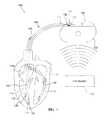
- FIG. 1is a schematic view of a system illustrating various embodiments of an inductive element for providing MRI compatibility in an implantable medical device lead.
- FIG. 2is a schematic view of an embodiment of a lead cap including an inductive element.
- FIG. 3is a schematic view of an embodiment of a lead adapter including an inductive element.
- FIG. 4is a schematic view of a proximal end of a lead illustrating an embodiment of an inductive coil insertable in an inner lumen of the lead.
- FIG. 5is a perspective view of an embodiment of a high inductance coil according to embodiments of the present disclosure.
- FIG. 1is a schematic view of a system 100 including an implantable medical device (IMD) 102 . As is shown, the IMD 102 is disposed in the vicinity of a magnetic resonance imaging (MRI) system 104 .
- the IMD 102includes a pulse generator 106 and one or more leads 110 deployed in a patient's heart H.
- FIG. 1shows three leads, referred to as leads 110 a , 110 b , and 110 c, implanted in various chambers of the heart H.
- the lead 110 ais an abandoned lead, and the leads 110 b and 110 c are active leads coupled to the pulse generator 106 .
- the pulse generator 106is typically implanted subcutaneously within an implantation location or pocket in the patient's chest or abdomen.
- the pulse generator 106may be any implantable medical device, known in the art or later developed, for delivering an electrical therapeutic stimulus to the patient.
- the pulse generator 106is a pacemaker, an implantable cardiac defibrillator, and/or includes both pacing and defibrillation capabilities. Any excess lead length, i.e., length beyond that needed to reach from the location of the pulse generator 106 to the desired intracardiac implantation site, is generally coiled up in the subcutaneous pocket near the pulse generator 106 .
- Each of the leads 110 a - 110 cincludes a distal end 112 and a proximal end 114 (shown only on lead 110 c for ease of illustration).
- Each of the leads 110 a - 110 cincludes a connector 116 at the proximal end 114 .
- a conductor 118extends through the lead body of each of the leads 110 a - 110 c , and is coupled to the connector 116 at the proximal end 114 and to one or more electrodes 120 at the distal end 112 .
- the connector 116 , conductor 118 , and electrode 120are labeled only on lead 110 c , but leads 110 a and 110 b can include similarly configured and located elements. It is noted that while one conductor 118 is shown, more than one conductor can be provided extending within each lead body.
- the conductor 118is covered by an outer insulating layer that forms the lead body. In some embodiments, the conductor 118 defines a conductor lumen 132 that extends through the lead 110 (e.g., lead 110 c ) from the proximal end 114 to the distal end 112 of the lead 110 .
- the connector 116couples each of the leads 110 b and 110 c to the pulse generator 106 to electrically connect the one or more electrodes 120 on the leads 110 b, 110 c to the pulse generator 106 via the conductor 118 .
- the connector 116 of the lead 110 ais configured for connection to the pulse generator 106 , but is disconnected.
- a leade.g., lead 110 a
- a bandoned leadthat is not connected to a pulse generator 106 and subsequently left in the heart H is termed an “abandoned lead.”
- the leads 110 b and 110 coperate to convey electrical signals and stimuli between the heart H and the pulse generator 106 .
- the lead 110 ais implanted in the right atrium
- the lead 110 bis implanted in the left ventricle
- the lead 110 cis implanted into the right ventricle.
- the leads 110 a - 110 center the vascular system through a vascular entry site formed in the wall of a left subclavian vein, extending through a brachiocephalic vein and a superior vena cava.
- the leads 110 a - 110 cmay enter the vascular system through a right subclavian vein, a left axillary vein, a left external jugular, an internal jugular, or a left brachiocephalic vein.
- the electrical signals and stimuli conveyed by the pulse generator 106are carried to the electrode 120 at the distal end 112 of the leads 110 b , 110 c by the conductor 118 .
- the electromagnetic radiation produced by the MRI system 104may be picked up by the conductor 118 of each of the leads 110 a - 110 c , regardless of whether the leads 110 a - 110 c are connected to the pulse generator 106 .
- the electromagnetic energyis transferred through the leads 110 a - 110 c to the electrode 120 in contact with the target tissue, which may lead to elevated temperatures at the point of contact.
- a device to transform a non-MR conditional lead into an MR conditional leadcan include, for example, a lead cap 140 including an inductive element secured to the proximal end 114 of the lead, as shown attached to the lead 110 a .
- a lead cap 140 according to the present disclosureis described below with regard to FIG. 2 .
- a second example device to transform a non-MR conditional lead into an MR conditional leadcan include a lead adapter 142 including an inductive element is secured to the proximal end 114 of the lead, as shown coupled to the proximal end of the lead 110 b .
- An embodiment of the lead adapter 142 according to the present disclosureis described herein with regard to FIG. 3 .
- a third example devicecan include an inductive coil 144 is positioned near the distal end 112 of the lead in the conductor lumen 132 , as shown at the distal end of the lead 110 c .
- An embodiment of the inductive coil 144 according to the present disclosureis described herein with regard to FIG. 4 .
- FIG. 2is a schematic illustration of a lead cap 140 configured to couple to the connector 116 at the proximal end 114 of the lead 110 a ( FIG. 1 ).
- the lead cap 140has a distal end portion 204 and a proximal end portion 206 .
- the lead cap 140includes an insulative housing 208 , a port 210 , and an inductive element 212 .
- the insulative housing 208extends from the distal end portion 204 to the proximal end portion 206 .
- the insulative housing 208can include an outer wall 214 and an inner wall 216 and a lumen 218 defined within the inner wall 216 and extending from the proximal end portion 206 to the distal end portion 204 of the housing 208 .
- the port 210provides an opening to the lumen 218 at the distal end portion 204 .
- the port 210 and lumen 218are configured to receive and retain the connector 116 .
- the inductive element 212can be disposed around at least a portion of the port 210 and positioned within the housing 208 such that the inductive element 212 surrounds at least a portion of the connector 116 from the non-MR conditional lead when the connector is received in the lumen 218 .
- the inductive element 212can be a high inductance coil.
- the housing 208can be formed of a polymer. In some embodiments, the housing 208 is formed of a polymeric biocompatible material. Exemplary materials that may be used for the housing 208 is include, but are not limited to, expanded polytetrafluoroethylene (ePTFE), layered ePTFE, polytetrafluoroethylene (PTFE), polyethylene terephthalate (PETE), ethylene/tetrafluoroethylene copolymer (ETFE), fluorinated ethylene propylene (FEP), polyether ether ketone (PEEK), polyamides, polyimides, para-aramid synthetic fibers, and polyurethane, among other materials.
- ePTFEexpanded polytetrafluoroethylene
- PTFEpolytetrafluoroethylene
- PETEpolyethylene terephthalate
- ETFEethylene/tetrafluoroethylene copolymer
- FEPfluorinated ethylene propylene
- PEEKpolyether ether ketone
- the lead cap 140couples with the connector 116 of the lead 110 a to electrically terminate the lead 110 a .
- the lead cap 140further includes a connector block 226 .
- the connector block 226can be electrically coupled to the inductive element 212 .
- the connector block 226is positioned around the lumen 218 within the housing 208 such that the connector block 226 is electrically connectable to a connector 116 disposed within the lumen 218 .
- the connector block 226is mechanically and electrically couplable to the connector 116 using a fixation mechanism (not shown), such as one or more set screws.
- the connector block 226operates to electrically couple the inductive element 212 to the connector 116 .
- the lead cap 140may not include the connector block 226 , which results in the inductive element 212 not being electrically connected to the connector 116 . In such embodiments, the inductive element 212 “floats” over the connector 116 .
- the inductive element 212can include a single filar 230 that is helically wound with a plurality of turns around a longitudinal axis A of the lumen 218 in a particular winding direction W, for example, a left-handed (LH) winding direction.
- the inductive element 212can include two or more filars (see, e.g., FIG. 5 ).
- the inductive element 212can also have a coil pitch, defined as a length from the center of a turn of a wire of the inductive element 212 to the center of an adjacent turn of the wire of the inductive element 212 , of between about one and two times the diameter of the filar 230 .
- the inductance of the inductive element 212can be determined, in part, by its geometric properties, including whether the inductive element 212 is straight or coiled. For a coiled or wound inductive element 212 , several parameters influence its inductance, including the coil pitch, the outer diameter, the cross-sectional area of the inductive element 212 , and the number of filars 230 in the inductive element 212 . Thus, the dimensions and characteristics of the inductive element 212 may be selected to minimize the effects of MRI fields on the performance and response of the lead 110 a.
- the inductive element 212is wound in the same direction W as the conductor 118 in the lead 110 a .
- the inductive element 212can also be coiled in the same LH winding direction.
- the inductive element 212has a higher inductance than the conductor 118 , so the overall inductance of the lead 110 a is increased by coupling the inductive element 212 to the conductor 118 . As a result, the amount of MRI induced current on the conductor 118 is reduced.
- the lead cap 140can be placed over the proximal end 114 of the lead 110 a .
- the port 210receives the connector 116 of the lead 110 a , which traverses through the lumen 218 to the proximal end 206 of the lead cap 140 until the inductive element 212 is disposed around at least a portion of the connector 116 .
- the overall inductance of the lead 110 ais increased, thereby reducing the amount of MRI-induced current that is picked up and transmitted by the conductor 118 .
- the inductive element 212prevents or reduces temperature increase at the one or more electrodes 120 .
- FIG. 3is a schematic illustration of a lead adapter 142 configured to couple to and cover the connector 116 at the proximal end 114 of the lead 110 b ( FIG. 1 ).
- the lead adapter 142has a distal end portion 304 , a proximal end portion 306 , and an intermediate portion 308 .
- the lead adapter 142can include an insulative housing 310 , a port 312 , a lead adapter connector 314 , and an inductive element 315 .
- the insulative housing 310extends from the distal end portion 304 to the intermediate portion 308 .
- the insulative housing 310includes an outer wall 316 , an inner wall 318 , and a lumen 320 defined within the inner wall 318 and extending from a proximal end portion 322 to a distal end portion 324 of the housing 310 .
- the port 312provides an opening to the lumen 320 at the distal end portion 304 of the lead adapter 142 .
- the port 312 and lumen 320are configured to receive and retain the connector 116 on the lead 110 b .
- the inductive element 315can be disposed around at least a portion of the port 312 and positioned within the housing 310 such that the inductive element 315 surrounds at least a portion of the connector 116 from the non-MR conditional lead when the connector 116 is received in the lumen 320 .
- the inductive element 315is a high inductance coil.
- the housing 310can be formed of a polymer. In some embodiments, the housing 310 is formed of a polymeric biocompatible material. Exemplary materials that may be used for the housing 310 is include, but are not limited to, expanded ePTFE, layered ePTFE, PTFE, PETE, ETFE, FEP, PEEK, polyamides, polyimides, para-aramid synthetic fibers, polyurethane, and silicone, among others.
- the lead adapter 142can further include a connector block 332 .
- the connector block 332can be electrically coupled to the inductive element 315 .
- the connector block 332is positioned around the lumen 320 within the housing 310 such that the connector block 332 is electrically connectable to a connector 116 disposed within the lumen 320 .
- the connector block 332is mechanically and electrically couplable to the connector 116 using a fixation mechanism (not shown), such as one or more set screws.
- a fixation mechanismnot shown
- the lead adapter 142may not include the connector block 332 , which results in the inductive element 315 not being electrically connected to the connector 116 . In such embodiments, the inductive element 315 “floats” over the connector 116 .
- the inductive element 315can include a single filar 340 that is helically wound with a plurality of turns around a longitudinal axis of the lumen 320 in a particular winding direction, for example, a left-handed (LH) winding direction.
- the inductive element 315includes two or more filars (see, e.g., FIG. 5 ).
- the inductive element 315can also have a coil pitch of between about one and two times the diameter of the filar 340 .
- the inductance of the inductive element 315is determined, in part, by its geometric properties, including whether the inductive element 315 is straight or coiled. For a coiled, or wound, inductive element 315 several parameters influence its inductance including: coil pitch, outer diameter, cross-sectional area of the inductive element 315 , and number of filars 340 in the inductive element 315 . Thus, the dimensions and characteristics of the inductive element 315 may be selected to minimize the effects of MRI fields on the performance and response of the lead 110 b.
- the inductive element 315can be wound in the same direction as the conductor 118 in the lead 110 b .
- the inductive element 315can also be coiled in the same LH winding direction.
- the inductive element 315can be configured to increase the overall inductance of the lead 110 b to reduce the amount of MRI induced currents on the conductor 118 .
- the lead adapter 142can be placed over the proximal end 114 of the lead 110 b .
- the port 312receives the connector 116 of the lead 110 b , which traverses through the lumen 320 to the proximal end portion 322 of the housing 310 until the inductive element 315 is disposed around at least a portion of the connector 116 .
- the lead adapter connector 314is then coupled to the pulse generator 106 .
- the overall inductance of the lead 110 bis increased, thereby reducing the amount of MRI-induced current that is picked up and transmitted by the conductor 118 .
- the inductive element 315prevents or reduces temperature increase at the one or more electrodes 120 , and can prevent or reduce the amount of current injected into the pulse generator 106 .
- FIG. 4is a schematic illustration of a portion of the lead 110 c with an embodiment of the inductive element 144 being inserted into the proximal end of the connector 116 .
- the inductive element 144can be configured to traverse through the conductor lumen 132 of the conductor 118 extending through the lead 110 c .
- the inductive element 144is positioned at the distal end portion 112 of the lead 110 c proximate to the one or more electrodes 120 .
- the inductive element 144increases the inductance of the conductor 118 , thereby reducing the heating of the one or more electrodes at the distal end 112 of the lead 110 c.
- the inductive element 144can be guided using an insertion tool (not shown) into the lumen 132 of the conductor 118 and moved toward the distal end portion 112 of the lead 110 c proximate to the electrode 120 .
- the insertion tool usedcan be a guide wire or a stylet. Other insertion tools can also be used for the purpose of guiding the inductive element 144 through the lead 110 c .
- the inductive element 144may be a high inductance coil and can include a wire or filar 402 wound into a coil with an outer diameter 404 smaller than the inner diameter of the conductor 118 .
- the inductive element 144can serve as a micro conductor for reducing the MRI field induced heating in the one or more electrodes 120 .
- the inductive element 144may be employed in lieu of or in addition to the lead cap 140 or the lead adapter 142 as discussed herein with respect to FIGS. 2 and 3 , respectively.
- FIG. 5is a perspective view of an inductive element 500 , including one or more filars 502 .
- the inductive element 500is an alternative configuration to the coiled inductive elements as described herein with regard to FIGS. 2-4 .
- one or more filars 502 of the inductive element 500are wound in a plurality of coil layers.
- a first coil layer 510can be wound in a first winding direction B 1
- a second coil layer 512can be coaxial with the first winding and wound in a second winding direction B 2 opposite the first winding direction
- a third coil layer 514can be coaxial with the first and second windings and wound in the first winding direction B 1 .
- the inductive element 500may be employed for the inductive elements described herein, including the inductive element 212 in the lead cap 140 ( FIG. 2 ), the inductive element 315 in the lead adapter 142 ( FIG. 3 ), and the inductive element 144 insertable in the conductor lumen 132 ( FIG. 4 ).
- each of the plurality of coil layershas been removed to illustrate each of the underlying layers such as 510 and 512 .
- the filars 502 of the inductive element 500are co-radially wound along a direction for example, direction B 1 to form the first coil layer 510 with a close pitch.
- the filars 502are then wound back on themselves in the reverse direction over and coaxially with the first coil layer 510 .
- the pitch of the second coil layer 512may be greater than the pitch of the first coil layer 512 , and winding in reverse direction results in the formation of second coil layer 512 over the first coil layer 510 .
- the filars 502are then wound back on themselves again, reversing direction from the second coil layer 512 (i.e., in the same direction as the inner first coil layer 510 ) to form the third coil layer 514 over the second coil layer 512 .
- the pitch of the third coil layer 514may be smaller than the pitch of the second coil layer 512 .
- the inductive element 500includes two to fifty filars 502 .
- the diameter of each filar 502can be in the range of about 0.001 inch to 0.010 inch (0.003-0.025 cm).
- the filarsmay be composed of a biocompatible material, including, but not limited to, gold (Au), silver (Ag), Nitinol, titanium (Ti), platinum (Pt), iridium (Ir), a nickel-cobalt base alloy (MP35N), or stainless steel.
- Each of the filarsmay also include an insulation layer (not shown) of a biocompatible and dielectric material, such as, for example, Teflon, nylon, polymers, PTFE, ETFE, silicone, polyurethane, PEEK, and/or epoxy.
- the thickness of the insulation layermay be less than about 0.005 inch (0.01 cm). In some embodiments, the outside diameter of the conductive assembly is less than about 0.10 inch (0.25 cm).
Landscapes
- Health & Medical Sciences (AREA)
- Heart & Thoracic Surgery (AREA)
- Radiology & Medical Imaging (AREA)
- Engineering & Computer Science (AREA)
- Biomedical Technology (AREA)
- Nuclear Medicine, Radiotherapy & Molecular Imaging (AREA)
- Life Sciences & Earth Sciences (AREA)
- Animal Behavior & Ethology (AREA)
- General Health & Medical Sciences (AREA)
- Public Health (AREA)
- Veterinary Medicine (AREA)
- Cardiology (AREA)
- Neurology (AREA)
- Electrotherapy Devices (AREA)
- Magnetic Resonance Imaging Apparatus (AREA)
Abstract
Description
This application claims the benefit of Provisional Application No. 61/715,627, filed Oct. 18, 2012, which is incorporated herein by reference in its entirety.
The present invention relates to implantable medical devices. More particularly, the present invention relates to an inductive element configured to associate with an implantable medical device to reduce MRI-induced currents in the implantable medical device.
Magnetic resonance imaging (MRI) is a non-invasive imaging procedure that utilizes nuclear magnetic resonance techniques to render images within a patient's body. Typically, MRI systems employ the use of a magnetic coil having a magnetic field strength of between about 0.2 to 3 Teslas (T). During the procedure, the body tissue is briefly exposed to RF pulses of electromagnetic energy in a plane perpendicular to the magnetic field. The resultant electromagnetic energy from these pulses can be used to image the body tissue by measuring the relaxation properties of the excited atomic nuclei in the tissue.
During imaging, the electromagnetic fields produced by the MRI system may be picked up by implantable device leads used in implantable medical devices such as pacemakers or cardiac defibrillators. This energy may be transferred through the lead to the electrode in contact with the tissue, which may lead to elevated temperatures at the point of contact. The degree of tissue heating is typically related to factors such as the length of the lead, the conductivity or impedance of the lead, and the surface area of the lead electrodes. Exposure to a magnetic field may also induce an undesired voltage on the lead.
Discussed herein are various embodiments of an inductive element configured to associate with an implantable medical device lead to make the implantable medical device lead magnetic resonance (MR) conditional, as well as implantable medical device leads associated with such inductive elements.
In Example 1, a system includes a medical device lead including a connector at a proximal end of the lead, a conductor electrically connected to the connector at a proximal end of the conductor, and at least one electrode coupled to a distal end of the conductor. The system further includes a device securable to the proximal end of the lead including an inductive element. The device includes a port configured to receive the connector and position the inductive element around at least a portion of the connector.
In Example 2, the system according to Example 1, wherein the device comprises a lead cap configured to cover the proximal end of the lead.
In Example 3, the system according to Example 2, wherein the lead cap includes a connector block configured to electrically couple the lead cap with the connector on the lead to electrically terminate the lead.
In Example 4, the system according to any of Examples 1-3, wherein the device comprises a lead adapter.
In Example 5, the system according to Example 4, wherein the lead adapter further comprises a lead adapter connector configured to electrically couple with the connector on the lead, and wherein the lead adapter is configured to electrically and mechanically connect the lead to an implantable pulse generator.
In Example 6, the system according to either Example 4 or Example 5, wherein the lead adapter includes a connector block configured to electrically couple the lead adapter with the connector on the lead.
In Example 7, the system according to any of Examples 1-6, wherein the inductive element comprises a coil, and wherein a winding direction of the coil is same as a winding direction of the conductor.
In Example 8, the system according to any of Examples 1-7, wherein the conductor defines a lumen that extends through the lead, and wherein the system further comprises an inductive lumen coil positionable within the lumen proximate to the distal end of the conductor.
In Example 9, the system according to any of Examples 1-8, wherein the inductive element comprises one or more filars wound in a plurality of coil layers including a first coil layer of the one or more filars wound in a first winding direction, a second coil layer of the one or more filars coaxial with the first winding and wound in a second winding direction opposite the first winding direction, and a third coil layer of the one or more filars coaxial with the first and second windings and wound in the first winding direction.
In Example 10, a device for transforming a non-MR conditional lead into an MRI conditionally safe lead includes an insulative housing including a port configured to receive a connector of the non-MR conditional lead. The device further includes an inductive element disposed around at least a portion of the port and positioned within the housing such that the inductive element surrounds at least a portion of the connector from the non-MR conditional lead when the connector is received in the port.
In Example 11, the device according to Example 10, wherein the device is configured as a lead cap for covering the proximal end of the non-MR conditional lead.
In Example 12, the device according to either Example 10 or Example, 11, and further including a connector block configured to electrically couple the device with the connector on the lead such that the connector block electrically terminates the non-MR conditional lead.
In Example 13, the device according to any of Examples 10-12, wherein the device is configured as a lead adapter configured to electrically and mechanically connect the non-MR conditional lead to an implantable pulse generator, and wherein the device further comprises a lead adapter connector configured to electrically couple with the connector of the non-MR conditional lead.
In Example 14, the device according to Example 13, and further comprising a connector block configured to electrically couple the device with the connector on the non-MR conditional lead.
In Example 15, the device according to any of Examples 10-14, wherein the inductive element comprises a coil, and wherein a winding direction of the coil is the same as the winding direction of a conductor in the non-MR conditional lead.
In Example 16, the device according to any of Examples 10-15, wherein the inductive element comprises one or more filars wound in a plurality of coil layers, a first coil layer of the one or more filars wound in a first winding direction, a second coil layer of the one or more filars coaxial with the first winding and wound in a second winding direction opposite the first winding direction, and a third coil layer of the one or more filars coaxial with the first and second windings and wound in the first winding direction.
In Example 17, a lead assembly includes a non-MR conditional medical device lead including a connector at a proximal end of the lead, a conductor electrically connected to the connector at a proximal end of the conductor, and at least one electrode coupled to a distal end of the conductor. The lead assembly further comprises an inductive element secured to the proximal end of the lead and comprising a coil. The inductive element includes a port that receives the connector and positions the coil around at least a portion of the connector.
In Example 18, the lead assembly according to Example 17, wherein the device comprises a lead cap that covers the proximal end of the non-MR conditional medical device lead.
In Example 19, the lead assembly according to Example 17, wherein the device comprises a lead adapter, and wherein the lead adapter further comprises a lead adapter connector electrically coupled with the connector on the non-MR conditional medical device lead, and wherein the lead adapter is configured to electrically and mechanically connect the electrically coupled lead to an implantable pulse generator.
In Example 20, the lead assembly according to any of Examples 17-19, wherein the inductive element comprises a coil, and wherein a winding direction of the coil is the same as a winding direction of the conductor.
While multiple embodiments are disclosed, still other embodiments of the present invention will become apparent to those skilled in the art from the following detailed description, which shows and describes illustrative embodiments of the invention. Accordingly, the drawings and detailed description are to be regarded as illustrative in nature and not restrictive.
While the invention is amenable to various modifications and alternative forms, specific embodiments have been shown by way of example in the drawings and are described in detail below. The intention, however, is not to limit the invention to the particular embodiments described. On the contrary, the invention is intended to cover all modifications, equivalents, and alternatives falling within the scope of the invention as defined by the appended claims.
Thepulse generator 106 is typically implanted subcutaneously within an implantation location or pocket in the patient's chest or abdomen. Thepulse generator 106 may be any implantable medical device, known in the art or later developed, for delivering an electrical therapeutic stimulus to the patient. In various embodiments, thepulse generator 106 is a pacemaker, an implantable cardiac defibrillator, and/or includes both pacing and defibrillation capabilities. Any excess lead length, i.e., length beyond that needed to reach from the location of thepulse generator 106 to the desired intracardiac implantation site, is generally coiled up in the subcutaneous pocket near thepulse generator 106.
Each of the leads110a-110cincludes adistal end 112 and a proximal end114 (shown only onlead 110cfor ease of illustration). Each of the leads110a-110cincludes aconnector 116 at theproximal end 114. Aconductor 118 extends through the lead body of each of the leads110a-110c, and is coupled to theconnector 116 at theproximal end 114 and to one ormore electrodes 120 at thedistal end 112. For ease of illustration, theconnector 116,conductor 118, andelectrode 120 are labeled only onlead 110c, but leads110aand110bcan include similarly configured and located elements. It is noted that while oneconductor 118 is shown, more than one conductor can be provided extending within each lead body.
In some embodiments, theconductor 118 is covered by an outer insulating layer that forms the lead body. In some embodiments, theconductor 118 defines aconductor lumen 132 that extends through the lead110 (e.g., lead110c) from theproximal end 114 to thedistal end 112 of the lead110.
Theconnector 116 couples each of theleads pulse generator 106 to electrically connect the one ormore electrodes 120 on theleads pulse generator 106 via theconductor 118. As shown, theconnector 116 of the lead110ais configured for connection to thepulse generator 106, but is disconnected. A lead (e.g., lead110a) that is not connected to apulse generator 106 and subsequently left in the heart H is termed an “abandoned lead.”
As shown inFIG. 1 , theleads pulse generator 106. For example, in the illustrated embodiment, thelead 110ais implanted in the right atrium, thelead 110bis implanted in the left ventricle, and thelead 110cis implanted into the right ventricle. As shown, the leads110a-110center the vascular system through a vascular entry site formed in the wall of a left subclavian vein, extending through a brachiocephalic vein and a superior vena cava. In other embodiments, the leads110a-110cmay enter the vascular system through a right subclavian vein, a left axillary vein, a left external jugular, an internal jugular, or a left brachiocephalic vein. The electrical signals and stimuli conveyed by thepulse generator 106 are carried to theelectrode 120 at thedistal end 112 of theleads conductor 118.
In an MRI environment, as shown inFIG. 1 , the electromagnetic radiation produced by theMRI system 104 may be picked up by theconductor 118 of each of the leads110a-110c, regardless of whether the leads110a-110care connected to thepulse generator 106. The electromagnetic energy is transferred through the leads110a-110cto theelectrode 120 in contact with the target tissue, which may lead to elevated temperatures at the point of contact.
The devices as described in further detail herein include inductive elements (e.g., inductive coils) and are configured to associate with non-MR conditional leads to transform the leads into MR conditional leads. An MR conditional device poses no known hazards in a specified MRI environment with specified conditions of use. In some embodiments, a device to transform a non-MR conditional lead into an MR conditional lead can include, for example, alead cap 140 including an inductive element secured to theproximal end 114 of the lead, as shown attached to the lead110a. An embodiment of thelead cap 140 according to the present disclosure is described below with regard toFIG. 2 . A second example device to transform a non-MR conditional lead into an MR conditional lead can include alead adapter 142 including an inductive element is secured to theproximal end 114 of the lead, as shown coupled to the proximal end of thelead 110b. An embodiment of thelead adapter 142 according to the present disclosure is described herein with regard toFIG. 3 . A third example device can include aninductive coil 144 is positioned near thedistal end 112 of the lead in theconductor lumen 132, as shown at the distal end of thelead 110c. An embodiment of theinductive coil 144 according to the present disclosure is described herein with regard toFIG. 4 .
In some embodiments, thehousing 208 can be formed of a polymer. In some embodiments, thehousing 208 is formed of a polymeric biocompatible material. Exemplary materials that may be used for thehousing 208 is include, but are not limited to, expanded polytetrafluoroethylene (ePTFE), layered ePTFE, polytetrafluoroethylene (PTFE), polyethylene terephthalate (PETE), ethylene/tetrafluoroethylene copolymer (ETFE), fluorinated ethylene propylene (FEP), polyether ether ketone (PEEK), polyamides, polyimides, para-aramid synthetic fibers, and polyurethane, among other materials.
Thelead cap 140 couples with theconnector 116 of the lead110ato electrically terminate the lead110a. In some embodiments, such as in a unipolar lead, thelead cap 140 further includes aconnector block 226. Theconnector block 226 can be electrically coupled to theinductive element 212. Theconnector block 226 is positioned around thelumen 218 within thehousing 208 such that theconnector block 226 is electrically connectable to aconnector 116 disposed within thelumen 218. In some embodiments, theconnector block 226 is mechanically and electrically couplable to theconnector 116 using a fixation mechanism (not shown), such as one or more set screws. Thus, theconnector block 226 operates to electrically couple theinductive element 212 to theconnector 116. In other embodiments, thelead cap 140 may not include theconnector block 226, which results in theinductive element 212 not being electrically connected to theconnector 116. In such embodiments, theinductive element 212 “floats” over theconnector 116.
In the illustrated embodiment, theinductive element 212 can include asingle filar 230 that is helically wound with a plurality of turns around a longitudinal axis A of thelumen 218 in a particular winding direction W, for example, a left-handed (LH) winding direction. In some embodiments, theinductive element 212 can include two or more filars (see, e.g.,FIG. 5 ). Theinductive element 212 can also have a coil pitch, defined as a length from the center of a turn of a wire of theinductive element 212 to the center of an adjacent turn of the wire of theinductive element 212, of between about one and two times the diameter of the filar230.
The inductance of theinductive element 212 can be determined, in part, by its geometric properties, including whether theinductive element 212 is straight or coiled. For a coiled or woundinductive element 212, several parameters influence its inductance, including the coil pitch, the outer diameter, the cross-sectional area of theinductive element 212, and the number offilars 230 in theinductive element 212. Thus, the dimensions and characteristics of theinductive element 212 may be selected to minimize the effects of MRI fields on the performance and response of the lead110a.
In some embodiments, theinductive element 212 is wound in the same direction W as theconductor 118 in the lead110a. For example, if theconductor 118 is coiled in the LH winding direction, then theinductive element 212 can also be coiled in the same LH winding direction. Theinductive element 212 has a higher inductance than theconductor 118, so the overall inductance of the lead110ais increased by coupling theinductive element 212 to theconductor 118. As a result, the amount of MRI induced current on theconductor 118 is reduced.
In operation, thelead cap 140 can be placed over theproximal end 114 of the lead110a. Theport 210 receives theconnector 116 of the lead110a, which traverses through thelumen 218 to theproximal end 206 of thelead cap 140 until theinductive element 212 is disposed around at least a portion of theconnector 116. By surrounding at least a portion of theconnector 116 with theinductive element 212, the overall inductance of the lead110ais increased, thereby reducing the amount of MRI-induced current that is picked up and transmitted by theconductor 118. As a result, theinductive element 212 prevents or reduces temperature increase at the one ormore electrodes 120.
In some embodiments, thehousing 310 can be formed of a polymer. In some embodiments, thehousing 310 is formed of a polymeric biocompatible material. Exemplary materials that may be used for thehousing 310 is include, but are not limited to, expanded ePTFE, layered ePTFE, PTFE, PETE, ETFE, FEP, PEEK, polyamides, polyimides, para-aramid synthetic fibers, polyurethane, and silicone, among others.
In some embodiments, such as when thelead adapter 142 is used in association with a unipolar lead, thelead adapter 142 can further include aconnector block 332. Theconnector block 332 can be electrically coupled to theinductive element 315. Theconnector block 332 is positioned around thelumen 320 within thehousing 310 such that theconnector block 332 is electrically connectable to aconnector 116 disposed within thelumen 320. In some embodiments, theconnector block 332 is mechanically and electrically couplable to theconnector 116 using a fixation mechanism (not shown), such as one or more set screws. Thus, theconnector block 332 operates to electrically couple theinductive element 315 to theconnector 116. In other embodiments, thelead adapter 142 may not include theconnector block 332, which results in theinductive element 315 not being electrically connected to theconnector 116. In such embodiments, theinductive element 315 “floats” over theconnector 116.
In the illustrated embodiment, theinductive element 315 can include asingle filar 340 that is helically wound with a plurality of turns around a longitudinal axis of thelumen 320 in a particular winding direction, for example, a left-handed (LH) winding direction. In other embodiments, theinductive element 315 includes two or more filars (see, e.g.,FIG. 5 ). Theinductive element 315 can also have a coil pitch of between about one and two times the diameter of the filar340.
The inductance of theinductive element 315 is determined, in part, by its geometric properties, including whether theinductive element 315 is straight or coiled. For a coiled, or wound,inductive element 315 several parameters influence its inductance including: coil pitch, outer diameter, cross-sectional area of theinductive element 315, and number offilars 340 in theinductive element 315. Thus, the dimensions and characteristics of theinductive element 315 may be selected to minimize the effects of MRI fields on the performance and response of thelead 110b.
In some embodiments, theinductive element 315 can be wound in the same direction as theconductor 118 in thelead 110b. For example, if theconductor 118 is coiled in the LH winding direction, then theinductive element 315 can also be coiled in the same LH winding direction. Theinductive element 315 can be configured to increase the overall inductance of thelead 110bto reduce the amount of MRI induced currents on theconductor 118.
In operation, thelead adapter 142 can be placed over theproximal end 114 of thelead 110b. Theport 312 receives theconnector 116 of thelead 110b, which traverses through thelumen 320 to theproximal end portion 322 of thehousing 310 until theinductive element 315 is disposed around at least a portion of theconnector 116. Thelead adapter connector 314 is then coupled to thepulse generator 106. By surrounding at least a portion of theconnector 116 with theinductive element 315, the overall inductance of thelead 110bis increased, thereby reducing the amount of MRI-induced current that is picked up and transmitted by theconductor 118. As a result, theinductive element 315 prevents or reduces temperature increase at the one ormore electrodes 120, and can prevent or reduce the amount of current injected into thepulse generator 106.
Theinductive element 144 can be guided using an insertion tool (not shown) into thelumen 132 of theconductor 118 and moved toward thedistal end portion 112 of thelead 110cproximate to theelectrode 120. The insertion tool used can be a guide wire or a stylet. Other insertion tools can also be used for the purpose of guiding theinductive element 144 through thelead 110c. Theinductive element 144 may be a high inductance coil and can include a wire orfilar 402 wound into a coil with anouter diameter 404 smaller than the inner diameter of theconductor 118. Theinductive element 144 can serve as a micro conductor for reducing the MRI field induced heating in the one ormore electrodes 120. Theinductive element 144 may be employed in lieu of or in addition to thelead cap 140 or thelead adapter 142 as discussed herein with respect toFIGS. 2 and 3 , respectively.
InFIG. 5 , portions of each of the plurality of coil layers have been removed to illustrate each of the underlying layers such as510 and512. Thefilars 502 of theinductive element 500 are co-radially wound along a direction for example, direction B1 to form thefirst coil layer 510 with a close pitch. Thefilars 502 are then wound back on themselves in the reverse direction over and coaxially with thefirst coil layer 510. The pitch of thesecond coil layer 512 may be greater than the pitch of thefirst coil layer 512, and winding in reverse direction results in the formation ofsecond coil layer 512 over thefirst coil layer 510. Thefilars 502 are then wound back on themselves again, reversing direction from the second coil layer512 (i.e., in the same direction as the inner first coil layer510) to form thethird coil layer 514 over thesecond coil layer 512. The pitch of thethird coil layer 514 may be smaller than the pitch of thesecond coil layer 512.
In some embodiments, theinductive element 500 includes two to fiftyfilars 502. In some embodiments, the diameter of each filar502 can be in the range of about 0.001 inch to 0.010 inch (0.003-0.025 cm). The filars may be composed of a biocompatible material, including, but not limited to, gold (Au), silver (Ag), Nitinol, titanium (Ti), platinum (Pt), iridium (Ir), a nickel-cobalt base alloy (MP35N), or stainless steel. Each of the filars may also include an insulation layer (not shown) of a biocompatible and dielectric material, such as, for example, Teflon, nylon, polymers, PTFE, ETFE, silicone, polyurethane, PEEK, and/or epoxy. The thickness of the insulation layer may be less than about 0.005 inch (0.01 cm). In some embodiments, the outside diameter of the conductive assembly is less than about 0.10 inch (0.25 cm).
Various modifications and additions can be made to the exemplary embodiments discussed without departing from the scope of the present invention. For example, while the embodiments described above refer to the particular features, the scope of this invention also includes embodiments having different combinations of features and embodiments that do not include all of the described features. Accordingly, the scope of the present invention is intended to embrace all such alternatives, modifications, and variations as falling within the scope of the claims, together with all equivalents thereof.
Claims (20)
1. A system comprising:
a medical device lead including:
a connector at a proximal end of the lead;
a conductor electrically connected to the connector at a proximal end of the conductor; and
at least one electrode coupled to a distal end of the conductor; and
a device securable to the proximal end of the lead and comprising an inductive element, the device including a port configured to receive the connector and position the inductive element entirely circumferentially around at least a portion of the connector, wherein the device is configured such that, when the connector of the medical device lead is received within the port, the inductive element is not directly electrically connected to the conductor of the lead.
2. The system ofclaim 1 , wherein the device comprises a lead cap configured to cover the proximal end of the lead.
3. The system ofclaim 2 , wherein the lead cap includes a connector block configured to electrically couple the lead cap with the connector on the lead to electrically terminate the lead.
4. The system ofclaim 1 , wherein the device comprises a lead adapter.
5. The system ofclaim 4 , wherein the lead adapter further comprises a lead adapter connector configured to electrically couple with the connector on the lead, and wherein the lead adapter is configured to electrically and mechanically connect the lead to an implantable pulse generator.
6. The system ofclaim 5 , wherein the lead adapter includes a connector block configured to electrically couple the lead adapter with the connector on the lead.
7. The system ofclaim 1 , wherein the inductive element comprises a coil, and wherein a winding direction of the coil is the same as a winding direction of the conductor.
8. The system ofclaim 1 , wherein the conductor defines a lumen that extends through the lead, and wherein the system further comprises:
an inductive lumen coil positionable within the lumen proximate the distal end of the conductor.
9. The system ofclaim 1 , wherein the inductive element comprises one or more filars wound in a plurality of coil layers, a first coil layer of the one or more filars wound in a first winding direction, a second coil layer of the one or more filars coaxial with the first winding and wound in a second winding direction opposite the first winding direction, and a third coil layer of the one or more filars coaxial with the first and second windings and wound in the first winding direction.
10. A device for transforming a non-MR conditional lead into an MRI conditionally safe lead, the device comprising:
an insulative housing including a port configured to receive a connector of the non-MR conditional lead; and
an inductive element disposed around at least a portion of the port and positioned within the housing such that the inductive element entirely circumferentially surrounds at least a portion of the connector from the non-MR conditional lead when the connector is received in the port, the device configured such that the inductive element does not directly electrically connect to circuitry within a pulse generator when the connector of the non-MRI conditional lead is received within the port.
11. The device ofclaim 10 , wherein the device is configured as a lead cap for covering the proximal end of the non-MR conditional lead.
12. The device ofclaim 11 , and further comprising:
a connector block configured to electrically couple the device with the connector on the lead such that the connector block electrically terminates the non-MR conditional lead.
13. The device ofclaim 10 , wherein the device is configured as a lead adapter, and further comprises:
a lead adapter connector configured to electrically couple with the connector of the non-MR conditional lead, and wherein the lead adapter is configured to electrically and mechanically connect the non-MR conditional lead to an implantable pulse generator.
14. The device ofclaim 10 , further comprising a device comprising a lead cap that is configured to cover the proximal end of the lead when the lead is not connected to a pulse generator, the lead cap containing the inductive element.
15. The device ofclaim 10 , wherein the inductive element comprises a coil, and wherein a winding direction of the coil is the same as a winding direction of a conductor in the non-MR conditional lead.
16. The device ofclaim 10 , wherein the inductive element comprises one or more filars wound in a plurality of coil layers, a first coil layer of the one or more filars wound in a first winding direction, a second coil layer of the one or more filars coaxial with the first winding and wound in a second winding direction opposite the first winding direction, and a third coil layer of the one or more filars coaxial with the first and second windings and wound in the first winding direction.
17. A lead assembly comprising:
a non-MR conditional medical device lead including a connector at a proximal end of the lead, a conductor electrically connected to the connector at a proximal end of the conductor, and at least one electrode coupled to a distal end of the conductor; and
a lead cap securable to the proximal end of the lead, the lead cap including a port configured to receive the connector of the non-MRI conditional lead, and an inductive element comprising an inductor coil defining a lumen, the lead cap configured to electrically terminate the lead and inhibit MRI-induced currents in the conductor of the lead when the lead is not connected to a pulse generator, by covering the connector and positioning the inductor coil around at least a portion of the connector disposed within the port of the lead cap such that the connector extends within the lumen of the inductor coil.
18. The lead assembly ofclaim 17 , wherein the inductive element is not electrically connected to the connector when the connector is disposed within the port of the lead cap.
19. The lead assembly ofclaim 17 , wherein the lead cap is configured to not directly electrically connect the inductive element to the conductor when the port receives the connector.
20. The lead assembly ofclaim 17 , wherein the winding direction of the inductor coil is the same as a winding direction of the conductor.
Priority Applications (2)
| Application Number | Priority Date | Filing Date | Title |
|---|---|---|---|
| US14/056,746US8983623B2 (en) | 2012-10-18 | 2013-10-17 | Inductive element for providing MRI compatibility in an implantable medical device lead |
| US14/658,234US9504822B2 (en) | 2012-10-18 | 2015-03-15 | Inductive element for providing MRI compatibility in an implantable medical device lead |
Applications Claiming Priority (2)
| Application Number | Priority Date | Filing Date | Title |
|---|---|---|---|
| US201261715627P | 2012-10-18 | 2012-10-18 | |
| US14/056,746US8983623B2 (en) | 2012-10-18 | 2013-10-17 | Inductive element for providing MRI compatibility in an implantable medical device lead |
Related Child Applications (1)
| Application Number | Title | Priority Date | Filing Date |
|---|---|---|---|
| US14/658,234ContinuationUS9504822B2 (en) | 2012-10-18 | 2015-03-15 | Inductive element for providing MRI compatibility in an implantable medical device lead |
Publications (2)
| Publication Number | Publication Date |
|---|---|
| US20140114383A1 US20140114383A1 (en) | 2014-04-24 |
| US8983623B2true US8983623B2 (en) | 2015-03-17 |
Family
ID=49486735
Family Applications (2)
| Application Number | Title | Priority Date | Filing Date |
|---|---|---|---|
| US14/056,746ActiveUS8983623B2 (en) | 2012-10-18 | 2013-10-17 | Inductive element for providing MRI compatibility in an implantable medical device lead |
| US14/658,234Active2033-10-18US9504822B2 (en) | 2012-10-18 | 2015-03-15 | Inductive element for providing MRI compatibility in an implantable medical device lead |
Family Applications After (1)
| Application Number | Title | Priority Date | Filing Date |
|---|---|---|---|
| US14/658,234Active2033-10-18US9504822B2 (en) | 2012-10-18 | 2015-03-15 | Inductive element for providing MRI compatibility in an implantable medical device lead |
Country Status (6)
| Country | Link |
|---|---|
| US (2) | US8983623B2 (en) |
| EP (1) | EP2908903B1 (en) |
| JP (1) | JP6034499B2 (en) |
| CN (1) | CN104736196B (en) |
| AU (1) | AU2013331142B2 (en) |
| WO (1) | WO2014062966A1 (en) |
Cited By (4)
| Publication number | Priority date | Publication date | Assignee | Title |
|---|---|---|---|---|
| US20120191168A1 (en)* | 2009-07-24 | 2012-07-26 | Neuronexus Technologies, Inc. | Medical Device for Electrical Stimulation |
| US9199077B2 (en) | 2009-12-31 | 2015-12-01 | Cardiac Pacemakers, Inc. | MRI conditionally safe lead with multi-layer conductor |
| US9504822B2 (en) | 2012-10-18 | 2016-11-29 | Cardiac Pacemakers, Inc. | Inductive element for providing MRI compatibility in an implantable medical device lead |
| US9504821B2 (en) | 2014-02-26 | 2016-11-29 | Cardiac Pacemakers, Inc. | Construction of an MRI-safe tachycardia lead |
Families Citing this family (5)
| Publication number | Priority date | Publication date | Assignee | Title |
|---|---|---|---|---|
| US9084883B2 (en) | 2009-03-12 | 2015-07-21 | Cardiac Pacemakers, Inc. | Thin profile conductor assembly for medical device leads |
| US9254380B2 (en) | 2009-10-19 | 2016-02-09 | Cardiac Pacemakers, Inc. | MRI compatible tachycardia lead |
| US8391994B2 (en) | 2009-12-31 | 2013-03-05 | Cardiac Pacemakers, Inc. | MRI conditionally safe lead with low-profile multi-layer conductor for longitudinal expansion |
| US8954168B2 (en) | 2012-06-01 | 2015-02-10 | Cardiac Pacemakers, Inc. | Implantable device lead including a distal electrode assembly with a coiled component |
| JP6069499B2 (en) | 2012-08-31 | 2017-02-01 | カーディアック ペースメイカーズ, インコーポレイテッド | Lead wire with low peak MRI heating |
Citations (306)
| Publication number | Priority date | Publication date | Assignee | Title |
|---|---|---|---|---|
| US3614692A (en) | 1970-06-02 | 1971-10-19 | Magnetech Ind Inc | Variable induction device |
| US4131759A (en) | 1977-08-10 | 1978-12-26 | United States Steel Corporation | Slip sleeve mechanism for a strength tapered caged armored electromechanical cable |
| US4135518A (en) | 1976-05-21 | 1979-01-23 | Medtronic, Inc. | Body implantable lead and electrode |
| US4146036A (en) | 1977-10-06 | 1979-03-27 | Medtronic, Inc. | Body-implantable lead with protector for tissue securing means |
| US4209019A (en) | 1979-01-05 | 1980-06-24 | Medtronic, Inc. | Stylet insertion guide and rotation control device for use with body implantable lead |
| US4253462A (en) | 1979-08-09 | 1981-03-03 | Medtronic, Inc. | Stylet |
| US4350169A (en) | 1979-01-05 | 1982-09-21 | Medtronic, Inc. | Flexible tip stiffening stylet for use with body implantable lead |
| US4381013A (en) | 1981-03-19 | 1983-04-26 | Medtronic, Inc. | "J" Stylet wire |
| US4404125A (en) | 1981-10-14 | 1983-09-13 | General Electric Company | Polyphenylene ether resin compositions for EMI electromagnetic interference shielding |
| US4437474A (en) | 1982-07-16 | 1984-03-20 | Cordis Corporation | Method for making multiconductor coil and the coil made thereby |
| US4484586A (en) | 1982-05-27 | 1984-11-27 | Berkley & Company, Inc. | Hollow conductive medical tubing |
| US4493329A (en) | 1982-08-19 | 1985-01-15 | Lynn Crawford | Implantable electrode having different stiffening and curvature maintaining characteristics along its length |
| US4574800A (en) | 1984-12-07 | 1986-03-11 | Cordis Corporation | Implanted lead extractor |
| US4643202A (en) | 1985-04-15 | 1987-02-17 | Cordis Corporation | Multi-material insulation sheath for pacer lead |
| US4643203A (en) | 1982-07-01 | 1987-02-17 | Molins Plc | Conveying and uniting rod-like articles of the tobacco industry |
| US4649938A (en) | 1985-04-29 | 1987-03-17 | Mcarthur William A | Tissue-stimulating electrode having sealed, low-friction extendable/retractable active fixation means |
| US4869970A (en) | 1986-07-14 | 1989-09-26 | Shipley Company Inc. | Radiation attenuation shielding |
| US5002067A (en) | 1989-08-23 | 1991-03-26 | Medtronic, Inc. | Medical electrical lead employing improved penetrating electrode |
| US5003975A (en) | 1988-04-19 | 1991-04-02 | Siemens-Pacesetter, Inc. | Automatic electrode configuration of an implantable pacemaker |
| US5020545A (en) | 1990-01-23 | 1991-06-04 | Siemens-Pacesetter, Inc. | Cardiac lead assembly and method of attaching a cardiac lead assembly |
| US5056516A (en) | 1989-11-02 | 1991-10-15 | Intermedics, Inc. | Implantable endocordial lead with torque-transmitting lanyard |
| US5074313A (en) | 1989-03-20 | 1991-12-24 | Cardiac Pacemakers, Inc. | Porous electrode with enhanced reactive surface |
| US5144960A (en) | 1991-03-20 | 1992-09-08 | Medtronic, Inc. | Transvenous defibrillation lead and method of use |
| US5201865A (en) | 1991-10-28 | 1993-04-13 | Medtronic, Inc. | Medical lead impedance measurement system |
| US5217010A (en) | 1991-05-28 | 1993-06-08 | The Johns Hopkins University | Ecg amplifier and cardiac pacemaker for use during magnetic resonance imaging |
| US5222506A (en) | 1991-07-29 | 1993-06-29 | Medtronic, Inc. | Implantable medical lead with electrical cross-over adaptor |
| US5231996A (en) | 1992-01-28 | 1993-08-03 | Medtronic, Inc. | Removable endocardial lead |
| US5241957A (en) | 1991-11-18 | 1993-09-07 | Medtronic, Inc. | Bipolar temporary pacing lead and connector and permanent bipolar nerve wire |
| US5243911A (en) | 1990-09-18 | 1993-09-14 | Dow Robert L | Attenuator for protecting electronic equipment from undesired exposure to RF energy and/or lightning |
| US5246014A (en) | 1991-11-08 | 1993-09-21 | Medtronic, Inc. | Implantable lead system |
| US5259395A (en) | 1992-01-15 | 1993-11-09 | Siemens Pacesetter, Inc. | Pacemaker lead with extendable retractable lockable fixing helix |
| US5300108A (en) | 1993-01-05 | 1994-04-05 | Telectronics Pacing Systems, Inc. | Active fixation lead with a dual-pitch, free spinning compound screw |
| US5324322A (en) | 1992-04-20 | 1994-06-28 | Case Western Reserve University | Thin film implantable electrode and method of manufacture |
| US5330522A (en) | 1992-12-29 | 1994-07-19 | Siemens Pacesetter, Inc. | Ring electrode for a multilumen lead and method of constructing a multilumen lead |
| US5354327A (en) | 1993-04-07 | 1994-10-11 | Medtronic, Inc. | Conductor coil with specific ratio of torque to bending stiffness |
| US5370666A (en) | 1992-06-05 | 1994-12-06 | Siemens-Elema Ab | Pacemaker with power-consuming component inhibited during storage |
| US5378234A (en) | 1993-03-15 | 1995-01-03 | Pilot Cardiovascular Systems, Inc. | Coil polymer composite |
| US5387199A (en) | 1992-02-24 | 1995-02-07 | Baxter International Inc. | Polymer blends for torque transmitting catheters |
| US5417208A (en) | 1993-10-12 | 1995-05-23 | Arrow International Investment Corp. | Electrode-carrying catheter and method of making same |
| US5425755A (en) | 1992-12-04 | 1995-06-20 | Pacesetter, Inc. | Rotatable pin, screw-in pacing and sensing lead having Teflon-coated conductor coil |
| US5456707A (en) | 1993-10-22 | 1995-10-10 | Vitatron Medical Bv | Pacing lead with improved torsion characteristics |
| US5476485A (en) | 1993-09-21 | 1995-12-19 | Pacesetter, Inc. | Automatic implantable pulse generator |
| US5483022A (en) | 1994-04-12 | 1996-01-09 | Ventritex, Inc. | Implantable conductor coil formed from cabled composite wire |
| WO1996006655A1 (en) | 1994-08-29 | 1996-03-07 | Angeion Corporation | Low profile defibrillation catheter |
| US5522872A (en) | 1994-12-07 | 1996-06-04 | Ventritex, Inc. | Electrode-conductor sleeve joint for cardiac lead |
| US5522875A (en) | 1994-07-28 | 1996-06-04 | Medtronic, Inc. | Medical electrical lead system having a torque transfer stylet |
| US5534018A (en) | 1994-11-30 | 1996-07-09 | Medtronic, Inc. | Automatic lead recognition for implantable medical device |
| US5542173A (en) | 1993-09-24 | 1996-08-06 | Ventritex, Inc. | Method of making flexible defibrillation electrode |
| US5545205A (en) | 1989-12-08 | 1996-08-13 | Cardiac Pacemakers, Inc. | Unitary intravascular defibrillating catheter with bipolar sensing |
| US5549646A (en) | 1994-12-06 | 1996-08-27 | Pacesetter, Inc. | Periodic electrical lead intergrity testing system and method for implantable cardiac stimulating devices |
| US5554139A (en) | 1993-12-24 | 1996-09-10 | Terumo Kabushiki Kaisha | Catheter |
| US5574249A (en) | 1994-07-18 | 1996-11-12 | Lindsay Audiophile Inc. | High resistivity inner shields for cabinets housing electronic circuitry |
| US5584873A (en) | 1995-05-08 | 1996-12-17 | Medtronic, Inc. | Medical lead with compression lumens |
| US5599576A (en) | 1995-02-06 | 1997-02-04 | Surface Solutions Laboratories, Inc. | Medical apparatus with scratch-resistant coating and method of making same |
| US5609622A (en) | 1993-02-01 | 1997-03-11 | W. L. Gore & Associates, Inc. | Implantable electrode with conductive polytetrafluoroethylene elecrode |
| US5618208A (en) | 1994-06-03 | 1997-04-08 | Siemens Medical Systems, Inc. | Fully insulated, fully shielded electrical connector arrangement |
| US5727552A (en) | 1996-01-11 | 1998-03-17 | Medtronic, Inc. | Catheter and electrical lead location system |
| US5727553A (en) | 1996-03-25 | 1998-03-17 | Saad; Saad A. | Catheter with integral electromagnetic location identification device |
| US5728149A (en) | 1995-12-20 | 1998-03-17 | Medtronic, Inc. | Integral spiral band electrode for transvenous defibrillation leads |
| US5755742A (en) | 1996-11-05 | 1998-05-26 | Medtronic, Inc. | Cardioversion/defibrillation lead impedance measurement system |
| US5760341A (en) | 1996-09-10 | 1998-06-02 | Medtronic, Inc. | Conductor cable for biomedical lead |
| US5766227A (en) | 1997-03-04 | 1998-06-16 | Nappholz; Tibor A. | EMI detection in an implantable pacemaker and the like |
| US5800496A (en) | 1996-06-24 | 1998-09-01 | Medtronic, Inc. | Medical electrical lead having a crush resistant lead body |
| US5810887A (en) | 1996-08-23 | 1998-09-22 | Rhythm Technologies, Inc. | Temporary catheter |
| US5817136A (en) | 1997-05-02 | 1998-10-06 | Pacesetter, Inc. | Rate-responsive pacemaker with minute volume determination and EMI protection |
| US5824026A (en) | 1996-06-12 | 1998-10-20 | The Spectranetics Corporation | Catheter for delivery of electric energy and a process for manufacturing same |
| US5833715A (en) | 1992-09-03 | 1998-11-10 | Pacesetter, Inc. | Implantable stimulation lead having an advanceable therapeutic drug delivery system |
| US5849031A (en) | 1997-12-16 | 1998-12-15 | Medtronic, Inc. | Method and apparatus for termination of tachyarrhythmias |
| US5891114A (en) | 1997-09-30 | 1999-04-06 | Target Therapeutics, Inc. | Soft-tip high performance braided catheter |
| US5891179A (en) | 1997-11-20 | 1999-04-06 | Paceseter, Inc. | Method and apparatus for monitoring and displaying lead impedance in real-time for an implantable medical device |
| US5935159A (en) | 1996-12-19 | 1999-08-10 | Medtronic, Inc. | Medical electrical lead |
| US5957970A (en) | 1998-02-18 | 1999-09-28 | Medtronic, Inc. | Method of fabricating a medical electrical lead |
| US5957966A (en) | 1998-02-18 | 1999-09-28 | Intermedics Inc. | Implantable cardiac lead with multiple shape memory polymer structures |
| US5968087A (en) | 1996-12-19 | 1999-10-19 | Medtronic, Inc. | Multi-component lead body for medical electrical leads |
| US6016447A (en) | 1998-10-27 | 2000-01-18 | Medtronic, Inc. | Pacemaker implant recognition |
| US6057031A (en) | 1997-08-21 | 2000-05-02 | Gfe Metalle Und Materialien Gmbh. | Plastic substrate with thin metal-containing layer |
| US6078840A (en) | 1997-04-30 | 2000-06-20 | Medtronic, Inc. | Medical electrical lead having improved fixation |
| US6083216A (en) | 1999-01-05 | 2000-07-04 | Intermedics Inc. | Bent cardiac lead with shape memory torque coil |
| US6101417A (en) | 1998-05-12 | 2000-08-08 | Pacesetter, Inc. | Implantable electrical device incorporating a magnetoresistive magnetic field sensor |
| US6106522A (en) | 1993-10-14 | 2000-08-22 | Ep Technologies, Inc. | Systems and methods for forming elongated lesion patterns in body tissue using straight or curvilinear electrode elements |
| US6141593A (en) | 1998-11-10 | 2000-10-31 | Intermedics Inc. | Cardiac lead with ETEE coated DBS coil |
| US6143013A (en) | 1995-04-28 | 2000-11-07 | Target Therapeutics, Inc. | High performance braided catheter |
| US6178355B1 (en) | 1997-04-29 | 2001-01-23 | Medtronic, Inc. | Intracardiac defibrillation leads |
| US6192280B1 (en) | 1999-06-02 | 2001-02-20 | Medtronic, Inc. | Guidewire placed implantable lead with tip seal |
| US6208881B1 (en) | 1998-10-20 | 2001-03-27 | Micropure Medical, Inc. | Catheter with thin film electrodes and method for making same |
| US6249708B1 (en) | 1997-08-26 | 2001-06-19 | Angeion Corporation | Fluted channel construction for a multi-conductor catheter lead |
| US6256541B1 (en) | 1998-04-17 | 2001-07-03 | Cardiac Pacemakers, Inc. | Endocardial lead having defibrillation and sensing electrodes with septal anchoring |
| US6259954B1 (en) | 1999-02-18 | 2001-07-10 | Intermedics Inc. | Endocardial difibrillation lead with strain-relief coil connection |
| US6289250B1 (en) | 1998-05-27 | 2001-09-11 | Kabushiki Kaisha Cardio-Pacing Research Laboratory | Implantable electrode lead |
| US6295476B1 (en) | 1999-11-01 | 2001-09-25 | Medtronic, Inc. | Medical lead conductor fracture visualization method and apparatus |
| US6304784B1 (en) | 1999-06-15 | 2001-10-16 | Arizona Board Of Regents, Acting For And On Behalf Of Arizona State University | Flexible probing device and methods for manufacturing the same |
| US6317633B1 (en) | 1999-01-19 | 2001-11-13 | Medtronic, Inc. | Implantable lead functional status monitor and method |
| US6360129B1 (en) | 1999-12-13 | 2002-03-19 | Cardiac Pacemakers, Inc. | Mannitol/hydrogel cap for tissue-insertable connections |
| US20020065544A1 (en) | 1999-11-29 | 2002-05-30 | Medtronic, Inc. | Medical electrical lead having variable bending stiffness |
| US6400992B1 (en) | 1999-03-18 | 2002-06-04 | Medtronic, Inc. | Co-extruded, multi-lumen medical lead |
| US20020072769A1 (en) | 2000-12-11 | 2002-06-13 | Sergiu Silvian | System and method of protecting transformer-driven switches from external magnetic fields |
| US6428537B1 (en) | 1998-05-22 | 2002-08-06 | Scimed Life Systems, Inc. | Electrophysiological treatment methods and apparatus employing high voltage pulse to render tissue temporarily unresponsive |
| US20020111664A1 (en) | 1999-09-29 | 2002-08-15 | Cardiac Pacemakers, Inc. | Low profile, ventricular, transvenous, epicardial defibrillation lead |
| US20020128689A1 (en) | 2001-02-20 | 2002-09-12 | Connelly Patrick R. | Electromagnetic interference immune tissue invasive system |
| US6456888B1 (en) | 2000-08-18 | 2002-09-24 | Cardiac Pacemakers, Inc. | Geometry for coupling and electrode to a conductor |
| US20020144720A1 (en) | 1997-08-20 | 2002-10-10 | Zahorik Russell C. | Method and apparatus for selective removal of material from wafer alignment marks |
| US6493591B1 (en) | 2000-07-19 | 2002-12-10 | Medtronic, Inc. | Implantable active fixation lead with guidewire tip |
| US6501994B1 (en) | 1997-12-24 | 2002-12-31 | Cardiac Pacemakers, Inc. | High impedance electrode tip |
| US6501991B1 (en) | 2000-06-21 | 2002-12-31 | Medtronic, Inc. | Electrically-isolated multiple conductor lead body |
| US6510345B1 (en) | 2000-04-24 | 2003-01-21 | Medtronic, Inc. | System and method of bridging a transreceiver coil of an implantable medical device during non-communication periods |
| US6516230B2 (en) | 2000-04-26 | 2003-02-04 | Medtronic, Inc. | Medical electrical lead with fiber core |
| US20030028231A1 (en) | 2001-08-01 | 2003-02-06 | Cardiac Pacemakers, Inc. | Radiopaque drug collar for implantable endocardial leads |
| US6526321B1 (en) | 1998-06-05 | 2003-02-25 | Intermedics, Inc. | Method for making cardiac leads with zone insulated electrodes |
| US20030050680A1 (en) | 2001-09-07 | 2003-03-13 | Gibson Scott R. | Electronic lead for a medical implant device, method of making same, and method and apparatus for inserting same |
| US20030063946A1 (en) | 2000-12-18 | 2003-04-03 | Janet Williams | Disposable lotion applicator |
| US20030083726A1 (en) | 2001-10-31 | 2003-05-01 | Medtronic, Inc. | Method and apparatus for shunting induced currents in an electrical lead |
| US20030083723A1 (en) | 2001-10-31 | 2003-05-01 | Wilkinson Jeffrey D. | Apparatus and method for shunting induced currents in an electrical lead |
| US6564107B1 (en) | 2000-08-21 | 2003-05-13 | Cardiac Pacemakers, Inc. | Coil-less lead system |
| US20030093138A1 (en) | 2001-11-09 | 2003-05-15 | Osypka Thomas P. | High impedance drug eluting cardiac lead |
| US20030092303A1 (en) | 2001-11-09 | 2003-05-15 | Osypka Thomas P. | Multifilar conductor for cardiac leads |
| US20030139794A1 (en) | 2002-01-18 | 2003-07-24 | Jenney Christopher R. | Body implantable lead including one or more conductive polymer electrodes and methods for fabricating same |
| US20030140931A1 (en) | 2002-01-29 | 2003-07-31 | Zeijlemaker Volkert A. | Medical implantable system for reducing magnetic resonance effects |
| US20030144716A1 (en) | 2002-01-29 | 2003-07-31 | Reinke James D. | Method and apparatus for shunting induced currents in an electrical lead |
| US20030144718A1 (en) | 2002-01-29 | 2003-07-31 | Zeijlemaker Volkert A. | Method and apparatus for shielding coating for MRI resistant electrode systems |
| US20030144705A1 (en) | 2002-01-29 | 2003-07-31 | Medtronic, Inc. | Methods and apparatus for controlling a pacing system in the presence of EMI |
| US20030144720A1 (en) | 2002-01-29 | 2003-07-31 | Villaseca Eduardo H. | Electromagnetic trap for a lead |
| US20030144719A1 (en) | 2002-01-29 | 2003-07-31 | Zeijlemaker Volkert A. | Method and apparatus for shielding wire for MRI resistant electrode systems |
| US20030204217A1 (en) | 2002-04-25 | 2003-10-30 | Wilson Greatbatch | MRI-safe cardiac stimulation device |
| WO2003089045A2 (en) | 2002-04-11 | 2003-10-30 | Medtronic, Inc. | Implantable medical lead conductor insulation |
| US20040014355A1 (en) | 2002-07-10 | 2004-01-22 | Osypka Thomas P. | Low profile cardiac leads |
| US6701191B2 (en) | 2001-05-30 | 2004-03-02 | Cardiac Pacemakers, Inc. | Lead having composite tubing |
| US20040064174A1 (en) | 2002-09-27 | 2004-04-01 | Belden Elisabeth L. | Methods and apparatus for joining small diameter conductors within medical electrical leads |
| US20040064173A1 (en) | 2002-09-27 | 2004-04-01 | Hine Douglas S. | Cardiac vein lead with flexible anode and method for forming same |
| US20040064161A1 (en) | 2002-09-30 | 2004-04-01 | Gunderson Bruce D. | Method and apparatus for identifying lead-related conditions using lead impedance measurements |
| US6721604B1 (en) | 2000-07-27 | 2004-04-13 | Micronet Medical, Inc. | Reduced diameter, low resistance medical electrical lead |
| US6721600B2 (en) | 2000-01-19 | 2004-04-13 | Medtronic, Inc. | Implantable lead functional status monitor and method |
| US20040088033A1 (en) | 2002-10-31 | 2004-05-06 | Smits Karel F.A.A. | Implantable medical lead designs |
| JP2004141679A (en) | 1996-04-30 | 2004-05-20 | Target Therapeutics Inc | Superelastic alloy braiding structure |
| US20040097965A1 (en) | 2002-11-19 | 2004-05-20 | Gardeski Kenneth C. | Multilumen body for an implantable medical device |
| US20040122490A1 (en) | 2002-09-25 | 2004-06-24 | Medtronic, Inc. | Implantable medical device communication system with pulsed power biasing |
| US20040153049A1 (en) | 2002-10-10 | 2004-08-05 | Hewitt Todd J. | Wire braid-reinforced microcatheter |
| US20040162600A1 (en) | 2003-02-14 | 2004-08-19 | Medtronic, Inc. | Reverse wound electrodes |
| US20040167442A1 (en) | 2003-02-26 | 2004-08-26 | Shireman Brice L. | Elongated intracorporal medical device |
| US20040172117A1 (en) | 2001-03-29 | 2004-09-02 | Rolf Hill | Electrically conductive lead and a method of producing such a lead |
| US20040193140A1 (en) | 2003-03-27 | 2004-09-30 | Scimed Life Systems,Inc. | Medical device |
| US6813521B2 (en) | 2001-04-17 | 2004-11-02 | Medtronic, Inc. | Medical electrical lead |
| US6813251B1 (en) | 1999-07-27 | 2004-11-02 | Intel Corporation | Split Transaction protocol for a bus system |
| US20040243210A1 (en) | 2003-05-30 | 2004-12-02 | Morgan Kevin L. | Fixation of a left heart medical lead in the coronary sinus |
| US20040267107A1 (en) | 2003-06-24 | 2004-12-30 | Medtronic, Inc. | Medical electrical lead conductor formed from modified MP35N alloy |
| US6850803B1 (en) | 2000-06-16 | 2005-02-01 | Medtronic, Inc. | Implantable medical device with a recharging coil magnetic shield |
| US20050030322A1 (en) | 1998-06-25 | 2005-02-10 | Gardos Thomas R. | Perceptually based display |
| US6854994B2 (en) | 2001-04-19 | 2005-02-15 | Medtronic, Inc. | Medical electrical lead connector arrangement including anti-rotation means |
| US6866044B2 (en) | 2000-09-18 | 2005-03-15 | Cameron Health, Inc. | Method of insertion and implantation of implantable cardioverter-defibrillator canisters |
| US20050070972A1 (en) | 2003-09-26 | 2005-03-31 | Wahlstrand Carl D. | Energy shunt for producing an MRI-safe implantable medical device |
| US20050090886A1 (en) | 2001-02-20 | 2005-04-28 | Biophan Technologies, Inc. | Medical device with an electrically conductive anti-antenna geometrical shaped member |
| US20050113873A1 (en) | 2003-04-02 | 2005-05-26 | Biophan Technologies, Inc. | Device and method for preventing magnetic-resonance imaging induced damage |
| JP2005515854A (en) | 2002-01-29 | 2005-06-02 | メドトロニック・インコーポレーテッド | Medical electrical leads |
| US6906256B1 (en) | 2002-01-22 | 2005-06-14 | Nanoset, Llc | Nanomagnetic shielding assembly |
| US20050136385A1 (en) | 2003-12-19 | 2005-06-23 | Brian Mann | Flexible lead for digital cardiac rhythm management |
| US6925334B1 (en) | 2003-08-04 | 2005-08-02 | Pacesetter, Inc. | Implantable medical lead having multiple, jointly insulated electrical conductors |
| US20050177135A1 (en) | 2004-02-06 | 2005-08-11 | Hildebrand Keith R. | Delivery of a sympatholytic cardiovascular agent to the central nervous system to counter heart failure and pathologies associated with heart failure |
| US20050182471A1 (en) | 2002-01-22 | 2005-08-18 | Xingwu Wang | Magnetically shielded conductor |
| US20050197677A1 (en) | 2004-02-12 | 2005-09-08 | Stevenson Robert A. | Apparatus and process for reducing the susceptability of active implantable medical devices to medical procedures such as magnetic resonance imaging |
| US6949929B2 (en) | 2003-06-24 | 2005-09-27 | Biophan Technologies, Inc. | Magnetic resonance imaging interference immune device |
| US20050222657A1 (en) | 2004-03-30 | 2005-10-06 | Wahlstrand Carl D | MRI-safe implantable lead |
| US20050222659A1 (en) | 2004-03-30 | 2005-10-06 | Medtronic, Inc. | Lead electrode for use in an MRI-safe implantable medical device |
| US20050222656A1 (en) | 2004-03-30 | 2005-10-06 | Wahlstrand Carl D | MRI-safe implantable medical device |
| US20050222642A1 (en) | 2004-03-30 | 2005-10-06 | Medtronic, Inc. | Lead electrode for use in an MRI-safe implantable medical device |
| US20050222658A1 (en) | 2004-03-30 | 2005-10-06 | Medtronic, Inc. | Lead electrode for use in an MRI-safe implantable medical device |
| US20050246007A1 (en) | 2004-04-28 | 2005-11-03 | Medtronic, Inc. | Novel lead body assemblies |
| US20050267556A1 (en) | 2004-05-28 | 2005-12-01 | Allan Shuros | Drug eluting implants to prevent cardiac apoptosis |
| US20050272280A1 (en) | 2001-10-22 | 2005-12-08 | Osypka Thomas P | Lead adaptor having low resistance conductors and/or encapsulated housing |
| US20050283167A1 (en) | 2003-08-25 | 2005-12-22 | Biophan Technologies, Inc. | Medical device with an electrically conductive anti-antenna member |
| US6985755B2 (en) | 2002-04-17 | 2006-01-10 | Broadcom Corporation | Reduced power consumption wireless interface device |
| US20060009819A1 (en) | 2004-07-12 | 2006-01-12 | Medtronic, Inc. | Medical electrical device including novel means for reducing high frequency electromagnetic field-induced tissue heating |
| US6993373B2 (en) | 2000-11-24 | 2006-01-31 | Koninklijke Philips Electronics, N.V. | Invasive device provided with a segmented electrical connection conductor |
| US20060030774A1 (en) | 2003-06-24 | 2006-02-09 | Biophan Technologies, Inc. | Magnetic resonance imaging interference immune device |
| US6999818B2 (en) | 2003-05-23 | 2006-02-14 | Greatbatch-Sierra, Inc. | Inductor capacitor EMI filter for human implant applications |
| US20060037461A1 (en) | 2003-08-21 | 2006-02-23 | Masayuki Yasumura | Switching power supply circuit |
| US20060041293A1 (en) | 2004-08-19 | 2006-02-23 | Mehdizadeh Bruce R | Novel lead body-to-connector transition zone |
| US20060041294A1 (en) | 2004-08-20 | 2006-02-23 | Biophan Technologies, Inc. | Magnetic resonance imaging interference immune device |
| US20060041296A1 (en) | 2004-08-23 | 2006-02-23 | Medtronic, Inc. | Novel medical electrode configurations |
| US7013182B1 (en) | 2000-05-04 | 2006-03-14 | Cardiac Pacemakers, Inc. | Conductive polymer sheath on defibrillator shocking coils |
| CN1762510A (en) | 2004-09-02 | 2006-04-26 | 巨佰-雪莱公司 | Apparatus and process for reducing the susceptability of active implantable medical devices to medical procedures such as magnetic resonance imaging |
| US20060089691A1 (en) | 2004-10-21 | 2006-04-27 | Medtronic, Inc. | Implantable medical lead with axially oriented coiled wire conductors |
| US20060089696A1 (en) | 2004-10-21 | 2006-04-27 | Medtronic, Inc. | Implantable medical lead with reinforced outer jacket |
| US20060089695A1 (en) | 2004-10-21 | 2006-04-27 | Medtronic, Inc. | Implantable medical lead with helical reinforcement |
| US20060093685A1 (en) | 2004-10-28 | 2006-05-04 | Mower Thomas W | High mineral content dietary supplement |
| US7047075B2 (en) | 2003-04-17 | 2006-05-16 | Cardiac Pacemakers, Inc. | Apparatus for actively monitoring device for lead fixation in implantable tissue stimulators |
| US20060105066A1 (en) | 2003-07-22 | 2006-05-18 | Avoca, Inc. | Compounds for altering food intake in humans |
| US20060106442A1 (en) | 2004-05-19 | 2006-05-18 | The Board Of Trustees Of The Leland Stanford Junior University | Devices and methods for treating cardiac pathologies |
| US20060118758A1 (en) | 2004-09-15 | 2006-06-08 | Xingwu Wang | Material to enable magnetic resonance imaging of implantable medical devices |
| US20060129043A1 (en) | 2002-11-06 | 2006-06-15 | Ramot At Tel Aviv University Ltd. | System for and method of positioning cells and determing cellular activity thereof |
| US20060167536A1 (en) | 2005-01-25 | 2006-07-27 | Nygren Lea A | Method for fabrication of low-polarization implantable stimulation electrode |
| US20060200218A1 (en) | 2005-02-01 | 2006-09-07 | Wahlstrand Carl D | Extensible implantable medical lead |
| US7113827B2 (en) | 2003-01-17 | 2006-09-26 | Ela Medical S.A.S. | Determining the presence and type of probe associated with an active implantable medical device, in particular a cardiac pacemaker |
| WO2006105066A2 (en) | 2005-03-31 | 2006-10-05 | Medtronic. Inc. | Medical electrical lead with co-radial multi-conductor coil |
| US7127294B1 (en) | 2002-12-18 | 2006-10-24 | Nanoset Llc | Magnetically shielded assembly |
| US20060247748A1 (en) | 2005-04-29 | 2006-11-02 | Medtronic, Inc. | Lead electrode for use in an MRI-safe implantable medical device |
| US20060247747A1 (en) | 2005-04-29 | 2006-11-02 | Medtronic, Inc. | Lead electrode for use in an MRI-safe implantable medical device |
| US20060252314A1 (en) | 2005-05-04 | 2006-11-09 | Ergin Atalar | Electrical lead for an electronic device such as an implantable device |
| US20060253180A1 (en) | 2005-05-06 | 2006-11-09 | Cardiac Pacemakers, Inc. | Cable electrode assembly for a lead terminal and method therefor |
| US7135978B2 (en) | 2001-09-14 | 2006-11-14 | Calypso Medical Technologies, Inc. | Miniature resonating marker assembly |
| US20060271138A1 (en) | 2005-05-27 | 2006-11-30 | Biophan Technologies, Inc. | Electromagnetic interference immune pacing/defibrillation lead |
| US20060293737A1 (en) | 2005-06-22 | 2006-12-28 | Cardiac Pacemakers, Inc. | Multiple electrode implantable lead |
| US20070010702A1 (en) | 2003-04-08 | 2007-01-11 | Xingwu Wang | Medical device with low magnetic susceptibility |
| CN1905789A (en) | 2005-07-26 | 2007-01-31 | 严立贤 | Electromagnetic wave absorbing thin film structure and manufacturing method thereof |
| US20070027532A1 (en) | 2003-12-22 | 2007-02-01 | Xingwu Wang | Medical device |
| US7174220B1 (en) | 2004-03-16 | 2007-02-06 | Pacesetter, Inc. | Construction of a medical electrical lead |
| US7174219B2 (en) | 2004-03-30 | 2007-02-06 | Medtronic, Inc. | Lead electrode for use in an MRI-safe implantable medical device |
| US7205768B2 (en) | 2002-10-23 | 2007-04-17 | Koninklijke Philips Electronics N.V. | Connection lead for an electrical accessory device of an MRI system |
| WO2007047966A2 (en) | 2005-10-21 | 2007-04-26 | Surgi-Vision, Inc. | Mri-safe high impedance lead systems |
| US20070106332A1 (en) | 2005-11-04 | 2007-05-10 | Stephen Denker | MRI Compatible Implanted Electronic Medical Device |
| US20070112398A1 (en) | 2005-11-11 | 2007-05-17 | Greatbatch Ltd. | Tank filters placed in series with the lead wires or circuits of active medical devices to enhance mri compatibility |
| US7239916B2 (en) | 2001-07-17 | 2007-07-03 | Medtronic, Inc. | Method and apparatus for automatic implantable medical lead recognition and configuration |
| US20070156205A1 (en) | 2006-01-05 | 2007-07-05 | Larson Dennis E | Implantable medical device with inductive coil configurable for mechanical fixation |
| US7242987B2 (en) | 2003-06-19 | 2007-07-10 | Medtronic, Inc. | Medical lead adaptor |
| US20070179582A1 (en) | 2006-01-31 | 2007-08-02 | Marshall Mark T | Polymer reinforced coil conductor for torque transmission |
| US20070179577A1 (en) | 2006-01-31 | 2007-08-02 | Marshall Mark T | Medical electrical lead having improved inductance |
| US7257449B2 (en) | 2001-05-30 | 2007-08-14 | Cardiac Pacemakers, Inc. | Extendable/retractable lead having downsized lead body |
| US20070191914A1 (en) | 2006-02-16 | 2007-08-16 | Stessman Nicholas J | Mri detector for implantable medical device |
| US20070208383A1 (en) | 2002-04-11 | 2007-09-06 | Williams Terrell M | Medical electrical lead body designs incorporating energy dissipating shunt |
| CN101039619A (en) | 2004-08-09 | 2007-09-19 | 约翰斯·霍普金斯大学 | Implantable mri compatible stimulation leads and antennas and related systems and methods |
| WO2007118194A2 (en) | 2006-04-07 | 2007-10-18 | Biophan Technologies, Inc. | Resonance circuit for implantable devices and leads |
| US7289851B2 (en) | 2003-12-04 | 2007-10-30 | Medtronic, Inc. | Method and apparatus for identifying lead-related conditions using impedance trends and oversensing criteria |
| US20070255378A1 (en) | 2006-05-01 | 2007-11-01 | Polkinghorne Jeannette C | Lead with fibrous matrix coating and methods related thereto |
| US20080009905A1 (en) | 2006-06-23 | 2008-01-10 | Zeijlemaker Volkert A | Electrode system with shunt electrode |
| US20080033497A1 (en) | 2005-11-04 | 2008-02-07 | Cherik Bulkes | Mri compatible implanted electronic medical device and lead |
| US20080049376A1 (en) | 1998-11-04 | 2008-02-28 | Greatbatch Ltd. | Non-ferromagnetic tank filters in lead wires of active implantable medical devices to enhance mri compatibility |
| US20080051854A1 (en) | 2005-11-04 | 2008-02-28 | Cherik Bulkes | Mri compatible implanted electronic medical device with power and data communication capability |
| US20080058902A1 (en) | 2006-04-07 | 2008-03-06 | Biophan Technologies, Inc. | Resonance tuning module for implantable devices and leads |
| US20080057784A1 (en) | 2006-08-31 | 2008-03-06 | Cardiac Pacemakers, Inc. | Lead assembly including a polymer interconnect and methods related thereto |
| US7363090B2 (en) | 2001-04-13 | 2008-04-22 | Greatbatch Ltd. | Band stop filter employing a capacitor and an inductor tank circuit to enhance MRI compatibility of active implantable medical devices |
| WO2008051122A1 (en) | 2006-10-25 | 2008-05-02 | St. Jude Medical Ab | A medical implantable lead |
| US7369898B1 (en) | 2004-12-22 | 2008-05-06 | Pacesetter, Inc. | System and method for responding to pulsed gradient magnetic fields using an implantable medical device |
| US20080119917A1 (en) | 2006-11-17 | 2008-05-22 | Wolfgang Geistert | Electrode catheter for intervention purposes |
| US7378931B2 (en) | 2005-09-29 | 2008-05-27 | Murata Manufacturing Co., Ltd. | Multilayer coil component |
| US20080125754A1 (en) | 2006-07-17 | 2008-05-29 | Beer Lawrence P | Polymer tube with embedded electrically conductive patterns and method for providing electrically conductive paths in polymer tubing |
| US20080132985A1 (en) | 2006-11-30 | 2008-06-05 | Cardiac Pacemakers, Inc. | Rf rejecting lead |
| US20080129435A1 (en) | 2003-06-24 | 2008-06-05 | Medtronic, Inc. | Magnetic resonance imaging interference immune device |
| US20080140152A1 (en) | 2006-12-06 | 2008-06-12 | Spinal Modulation, Inc. | Implantable flexible circuit leads and methods of use |
| US7389148B1 (en) | 2004-05-05 | 2008-06-17 | Pacesetter, Inc. | Electrode design for defibrillation and/or sensing capabilities |
| US20080154348A1 (en) | 2006-12-18 | 2008-06-26 | Ergin Atalar | Mri compatible implantable devices |
| US20080208290A1 (en) | 2007-01-18 | 2008-08-28 | Medtronic, Inc. | Bi-directional connector assembly for an implantable medical device |
| US20080243218A1 (en) | 2007-03-19 | 2008-10-02 | Bottomley Paul A | Mri and rf compatible leads and related methods of operating and fabricating leads |
| US20080262584A1 (en) | 2007-03-19 | 2008-10-23 | Bottomley Paul A | Methods and apparatus for fabricating leads with conductors and related flexible lead configurations |
| US20080269831A1 (en)* | 2007-04-25 | 2008-10-30 | Erickson John H | Implantable pulse generator comprising mri current limiting windings in header structure |
| US7453344B2 (en) | 2005-10-14 | 2008-11-18 | Murata Manufacturing Co., Ltd. | Multilayer coil component |
| US20090005825A1 (en) | 2007-06-27 | 2009-01-01 | Medtronic, Inc. | Mri-safe defibrillator electrodes |
| US20090024197A1 (en) | 2007-07-18 | 2009-01-22 | Cardiac Pacemakers, Inc. | Elution control via geometric features of an implantable substance matrix |
| US20090024180A1 (en) | 2006-01-13 | 2009-01-22 | Universitat Duisburg-Essen | Stimulation system, in particular a cardiac pacemaker |
| US20090099440A1 (en) | 2007-10-11 | 2009-04-16 | Ingmar Viohl | Reduction of rf induced tissue heating using discrete winding patterns |
| US20090099555A1 (en) | 2007-10-11 | 2009-04-16 | Ingmar Viohl | Reduction of rf induced tissue heating using conductive surface pattern |
| US20090118610A1 (en) | 2005-11-29 | 2009-05-07 | Karmarkar Parag V | Mri-guided localization and/or lead placement systems, related methods, devices and computer program products |
| US20090149920A1 (en) | 2007-12-06 | 2009-06-11 | Yingbo Li | Leads with high surface resistance |
| US20090149933A1 (en) | 2007-12-06 | 2009-06-11 | Cardiac Pacemakers, Inc. | Implantable lead having a variable coil conductor pitch |
| US20090149934A1 (en) | 2007-12-06 | 2009-06-11 | Cardiac Pacemakers, Inc. | Implantable lead with shielding |
| US20090198314A1 (en) | 2008-02-06 | 2009-08-06 | Foster Arthur J | Lead with mri compatible design features |
| US20090204171A1 (en) | 2008-02-11 | 2009-08-13 | Masoud Ameri | Mri shielding in electrodes using ac pacing |
| US20090210022A1 (en) | 2006-05-16 | 2009-08-20 | Koninklijke Philips Electronics, N.V. | Simplified biphasic defibrillator circuit with make-only switching |
| US20090270948A1 (en) | 2008-04-23 | 2009-10-29 | Enteromedics, Inc. | Antenna arrangements for implantable therapy device |
| US20090270956A1 (en) | 2008-04-25 | 2009-10-29 | Pacesetter, Inc. | Implantable medical lead configured for improved mri safety |
| WO2009137186A1 (en) | 2008-05-09 | 2009-11-12 | Cardiac Pacemakers, Inc. | Medical lead coil conductor with spacer element |
| US7630761B2 (en) | 2005-11-04 | 2009-12-08 | Cardiac Pacemakers, Inc. | Method and apparatus for modifying tissue to improve electrical stimulation efficacy |
| US20100106215A1 (en) | 2008-10-23 | 2010-04-29 | Stubbs Scott R | Systems and methods to detect implantable medical device configuaration changes affecting mri conditional safety |
| US20100103215A1 (en) | 2005-11-28 | 2010-04-29 | Akira Iriguchi | Jetting timing determining method, liquid-droplet jetting method and ink-jet printer |
| US20100114277A1 (en) | 2008-10-30 | 2010-05-06 | Pacesetter, Inc. | Mri compatible implantable medical lead and method of making same |
| US20100125320A1 (en) | 2008-11-20 | 2010-05-20 | Polkinghorne Jeannette C | Overmolded components for implantable medical leads and related methods |
| US20100137928A1 (en) | 2008-11-07 | 2010-06-03 | Duncan Jeffrey B | Implantable lead |
| WO2010078552A1 (en) | 2009-01-05 | 2010-07-08 | Kenergy, Inc. | Mri compatible electrical lead for an implantable electronic medical device |
| US20100174349A1 (en)* | 2001-04-13 | 2010-07-08 | Greatbatch Ltd. | System for terminating abandoned implanted leads to minimize heating in high power electromagnetic field environments |
| US20100234929A1 (en) | 2009-03-12 | 2010-09-16 | Torsten Scheuermann | Thin profile conductor assembly for medical device leads |
| US20100249892A1 (en) | 2009-03-26 | 2010-09-30 | Cherik Bulkes | Mri compatible implanted lead-electrode interface |
| US20100292744A1 (en) | 2007-11-14 | 2010-11-18 | St. Jude Medical Ab | A method of producing a ring electrode of an implantable lead |
| US20100331936A1 (en) | 2009-06-26 | 2010-12-30 | Christopher Perrey | Medical device lead including a unifilar coil with improved torque transmission capacity and reduced mri heating |
| US20110060394A1 (en) | 2009-09-10 | 2011-03-10 | Pacesetter, Inc. | Mri rf rejection module for implantable lead |
| US20110079423A1 (en)* | 2009-10-06 | 2011-04-07 | Pacesetter, Inc. | Mri compatible implantable lead |
| US20110087299A1 (en) | 2009-10-08 | 2011-04-14 | Masoud Ameri | Medical device lead including a flared conductive coil |
| US20110087302A1 (en) | 2009-10-09 | 2011-04-14 | Masoud Ameri | Mri compatible medical device lead including transmission line notch filters |
| US20110093054A1 (en) | 2009-10-19 | 2011-04-21 | Masoud Ameri | Mri compatible tachycardia lead |
| US7933662B2 (en) | 2006-04-26 | 2011-04-26 | Marshall Mark T | Medical electrical lead including an inductance augmenter |
| EP1852810B1 (en) | 2006-05-05 | 2011-05-25 | Quality Electro Dynamics, LLC. | IC tags/RFID tags for magnetic resonance imaging applications |
| US7953499B2 (en) | 2003-09-30 | 2011-05-31 | Cardiac Pacemakers, Inc. | Drug-eluting electrode |
| US20110160817A1 (en) | 2009-12-31 | 2011-06-30 | Foster Arthur J | Mri safe, multipolar active fixation stimulation lead with co-radial construction |
| US20110160829A1 (en) | 2009-12-31 | 2011-06-30 | Foster Arthur J | Mri conditionally safe lead with multi-layer conductor |
| US20110160828A1 (en) | 2009-12-31 | 2011-06-30 | Foster Arthur J | Mri conditionally safe lead with low-profile multi-layer conductor for longitudinal expansion |
| US20110160805A1 (en) | 2009-12-30 | 2011-06-30 | Blair Erbstoeszer | Implantable electrical lead including a cooling assembly to dissipate mri induced electrode heat |
| US20110160816A1 (en) | 2009-12-30 | 2011-06-30 | Stubbs Scott R | Apparatus to selectively increase medical device lead inner conductor inductance |
| US20110160818A1 (en)* | 2009-12-30 | 2011-06-30 | Roger Struve | Mri-conditionally safe medical device lead |
| US7991484B1 (en) | 2007-05-15 | 2011-08-02 | Pacesetter, Inc. | Active fixation medical lead and related method and system |
| US20110208280A1 (en) | 2010-02-19 | 2011-08-25 | Yingbo Li | Lead including conductors configured for reduced mri-induced currents |
| US8032230B1 (en) | 2007-10-09 | 2011-10-04 | Advanced Neuromodulation Systems, Inc. | Stimulation lead, stimulation system, and method for limiting MRI induced current in a stimulation lead |
| US20110288403A1 (en) | 2006-11-09 | 2011-11-24 | Greatbatch Ltd. | Multilayer helical wave filter for mri applications |
| US8099177B2 (en) | 2006-03-02 | 2012-01-17 | St. Jude Medical Ab | Implantable medical lead and method for the manufacture thereof |
| US20120016451A1 (en) | 2010-07-13 | 2012-01-19 | Roger Struve | Torque enhancement for mri-conditionally safe medical device lead |
| US20120022356A1 (en) | 2009-03-31 | 2012-01-26 | St Jude Medical Ab | implantable mri compatible medical lead with a rotatable control member |
| US8108054B2 (en) | 2009-02-04 | 2012-01-31 | Pacesetter, Inc. | Active fixation implantable medical lead configured to indicate via fluoroscopy embedment of helical anchor in cardiac tissue |
| US20120035698A1 (en) | 2006-11-09 | 2012-02-09 | Greatbatch Ltd. | Capacitor and inductor elements physically disposed in series whose lumped parameters are electrically connected in parallel to form a bandstop filter |
| US20120053662A1 (en) | 2010-08-30 | 2012-03-01 | Foster Arthur J | Lead conductor with pitch and torque control for mri conditionally safe use |
| US8145324B1 (en) | 2001-04-13 | 2012-03-27 | Greatbatch Ltd. | Implantable lead bandstop filter employing an inductive coil with parasitic capacitance to enhance MRI compatibility of active medical devices |
| US20120143273A1 (en) | 2010-12-07 | 2012-06-07 | Stubbs Scott R | Implantable lead including a spark gap to reduce heating in mri environments |
| US20120161901A1 (en) | 2006-06-08 | 2012-06-28 | Greatbatch Ltd. | Method of tuning bandstop filters for implantable medical leads |
| US20120253340A1 (en) | 2009-02-04 | 2012-10-04 | Greatbatch Ltd. | Composite rf current attenuator for a medical lead |
| US20130116764A1 (en) | 2011-11-04 | 2013-05-09 | Joseph Walker | Implantable medical device lead including inner coil reverse-wound relative to shocking coil |
| US8543209B2 (en) | 2011-03-07 | 2013-09-24 | Greatbatch Ltd. | Secondary header for an implantable medical device incorporating an ISO DF4 connector and connector cavity and/or an IS4 connector and connector cavity |
| US20130282093A1 (en) | 2012-04-20 | 2013-10-24 | Cardiac Pacemakers, Inc. | Implantable medical device lead including a unifilar coiled cable |
| US20130325093A1 (en) | 2012-06-01 | 2013-12-05 | Cardiac Pacemakers, Inc. | Implantable device lead including a distal electrode assembly with a coiled component |
| US20140067030A1 (en) | 2012-08-31 | 2014-03-06 | Cardiac Pacemakers, Inc. | Mri compatible lead coil |
| US8670828B2 (en) | 2009-05-26 | 2014-03-11 | Cardiac Pacemakers, Inc. | Method and devices for coupling a lead conductor member to a functional component |
| US8676344B2 (en) | 2009-09-02 | 2014-03-18 | Cardiac Pacemakers Inc. | Polyisobutylene urethane, urea and urethane/urea copolymers and medical leads containing the same |
| US8682451B2 (en) | 2006-06-28 | 2014-03-25 | Cardiac Pacemakers, Inc. | Lead system having a non-stationary to stationary electrical interconnect and method therefor |
Family Cites Families (19)
| Publication number | Priority date | Publication date | Assignee | Title |
|---|---|---|---|---|
| US5649974A (en) | 1992-07-27 | 1997-07-22 | Angeion Corporation | Low profile defibrillation catheter |
| US5466253A (en) | 1993-04-27 | 1995-11-14 | Pacesetter, Inc. | Crush resistant multi-conductor lead body |
| US5580699A (en) | 1994-08-16 | 1996-12-03 | Ventritex, Inc. | Method for manufacturing implantable cardiac defibrillation electrodes using a laser beam material removal process |
| US5542174A (en) | 1994-09-15 | 1996-08-06 | Intel Corporation | Method and apparatus for forming solder balls and solder columns |
| US5676694A (en) | 1996-06-07 | 1997-10-14 | Medtronic, Inc. | Medical electrical lead |
| CA2309428A1 (en) | 1997-11-07 | 1999-05-20 | Prolifix Medical, Inc. | Methods and systems for treating obstructions in a body lumen |
| US6635069B1 (en) | 2000-10-18 | 2003-10-21 | Scimed Life Systems, Inc. | Non-overlapping spherical three-dimensional coil |
| AUPR090300A0 (en) | 2000-10-20 | 2000-11-16 | AMC Technologies Pty Limited | An electrical lead |
| JP2004271782A (en) | 2003-03-07 | 2004-09-30 | Alps Electric Co Ltd | Optical device with holder |
| JP4235482B2 (en) | 2003-04-22 | 2009-03-11 | オリエンタルモーター株式会社 | Control device for position control motor |
| US9203648B2 (en) | 2004-05-02 | 2015-12-01 | Thomson Reuters Global Resources | Online fraud solution |
| WO2007067632A2 (en) | 2005-12-06 | 2007-06-14 | Epi-Sci, Llc | Method and system for detecting electrophysiological changes in pre-cancerous and cancerous tissue and epithelium |
| US7584005B1 (en) | 2006-04-12 | 2009-09-01 | Pacesetter, Inc. | Steroid eluting pacing tip electrode |
| US8244375B2 (en) | 2008-08-25 | 2012-08-14 | Pacesetter, Inc. | MRI compatible lead |
| WO2010044019A1 (en)* | 2008-10-15 | 2010-04-22 | Koninklijke Philips Electronics N.V. | Probe for an implantable medical device |
| WO2012039654A1 (en) | 2010-09-20 | 2012-03-29 | St. Jude Medical Ab | Mri-compatible implantable medical lead |
| US20120101558A1 (en) | 2010-10-26 | 2012-04-26 | Pacesetter, Inc. | Implantable leads having coiled conductors to reduce rf-induced current |
| US8983623B2 (en) | 2012-10-18 | 2015-03-17 | Cardiac Pacemakers, Inc. | Inductive element for providing MRI compatibility in an implantable medical device lead |
| WO2015130753A1 (en) | 2014-02-26 | 2015-09-03 | Cardiac Pacemakers, Inc | Construction of an mri-safe tachycardia lead |
- 2013
- 2013-10-17USUS14/056,746patent/US8983623B2/enactiveActive
- 2013-10-17EPEP13783213.5Apatent/EP2908903B1/ennot_activeNot-in-force
- 2013-10-17CNCN201380053673.7Apatent/CN104736196B/ennot_activeExpired - Fee Related
- 2013-10-17WOPCT/US2013/065517patent/WO2014062966A1/enactiveApplication Filing
- 2013-10-17AUAU2013331142Apatent/AU2013331142B2/ennot_activeCeased
- 2013-10-17JPJP2015533322Apatent/JP6034499B2/ennot_activeExpired - Fee Related
- 2015
- 2015-03-15USUS14/658,234patent/US9504822B2/enactiveActive
Patent Citations (382)
| Publication number | Priority date | Publication date | Assignee | Title |
|---|---|---|---|---|
| US3614692A (en) | 1970-06-02 | 1971-10-19 | Magnetech Ind Inc | Variable induction device |
| US4135518A (en) | 1976-05-21 | 1979-01-23 | Medtronic, Inc. | Body implantable lead and electrode |
| US4131759A (en) | 1977-08-10 | 1978-12-26 | United States Steel Corporation | Slip sleeve mechanism for a strength tapered caged armored electromechanical cable |
| US4146036A (en) | 1977-10-06 | 1979-03-27 | Medtronic, Inc. | Body-implantable lead with protector for tissue securing means |
| US4209019A (en) | 1979-01-05 | 1980-06-24 | Medtronic, Inc. | Stylet insertion guide and rotation control device for use with body implantable lead |
| US4350169A (en) | 1979-01-05 | 1982-09-21 | Medtronic, Inc. | Flexible tip stiffening stylet for use with body implantable lead |
| US4253462A (en) | 1979-08-09 | 1981-03-03 | Medtronic, Inc. | Stylet |
| US4381013A (en) | 1981-03-19 | 1983-04-26 | Medtronic, Inc. | "J" Stylet wire |
| US4404125A (en) | 1981-10-14 | 1983-09-13 | General Electric Company | Polyphenylene ether resin compositions for EMI electromagnetic interference shielding |
| US4484586A (en) | 1982-05-27 | 1984-11-27 | Berkley & Company, Inc. | Hollow conductive medical tubing |
| US4643203A (en) | 1982-07-01 | 1987-02-17 | Molins Plc | Conveying and uniting rod-like articles of the tobacco industry |
| US4437474A (en) | 1982-07-16 | 1984-03-20 | Cordis Corporation | Method for making multiconductor coil and the coil made thereby |
| US4493329A (en) | 1982-08-19 | 1985-01-15 | Lynn Crawford | Implantable electrode having different stiffening and curvature maintaining characteristics along its length |
| US4574800A (en) | 1984-12-07 | 1986-03-11 | Cordis Corporation | Implanted lead extractor |
| US4643202A (en) | 1985-04-15 | 1987-02-17 | Cordis Corporation | Multi-material insulation sheath for pacer lead |
| US4649938A (en) | 1985-04-29 | 1987-03-17 | Mcarthur William A | Tissue-stimulating electrode having sealed, low-friction extendable/retractable active fixation means |
| US4869970A (en) | 1986-07-14 | 1989-09-26 | Shipley Company Inc. | Radiation attenuation shielding |
| US5003975A (en) | 1988-04-19 | 1991-04-02 | Siemens-Pacesetter, Inc. | Automatic electrode configuration of an implantable pacemaker |
| US5074313A (en) | 1989-03-20 | 1991-12-24 | Cardiac Pacemakers, Inc. | Porous electrode with enhanced reactive surface |
| US5002067A (en) | 1989-08-23 | 1991-03-26 | Medtronic, Inc. | Medical electrical lead employing improved penetrating electrode |
| US5056516A (en) | 1989-11-02 | 1991-10-15 | Intermedics, Inc. | Implantable endocordial lead with torque-transmitting lanyard |
| US5545205A (en) | 1989-12-08 | 1996-08-13 | Cardiac Pacemakers, Inc. | Unitary intravascular defibrillating catheter with bipolar sensing |
| US5020545A (en) | 1990-01-23 | 1991-06-04 | Siemens-Pacesetter, Inc. | Cardiac lead assembly and method of attaching a cardiac lead assembly |
| US5243911A (en) | 1990-09-18 | 1993-09-14 | Dow Robert L | Attenuator for protecting electronic equipment from undesired exposure to RF energy and/or lightning |
| US5144960A (en) | 1991-03-20 | 1992-09-08 | Medtronic, Inc. | Transvenous defibrillation lead and method of use |
| US5217010A (en) | 1991-05-28 | 1993-06-08 | The Johns Hopkins University | Ecg amplifier and cardiac pacemaker for use during magnetic resonance imaging |
| US5222506A (en) | 1991-07-29 | 1993-06-29 | Medtronic, Inc. | Implantable medical lead with electrical cross-over adaptor |
| US5201865A (en) | 1991-10-28 | 1993-04-13 | Medtronic, Inc. | Medical lead impedance measurement system |
| US5246014A (en) | 1991-11-08 | 1993-09-21 | Medtronic, Inc. | Implantable lead system |
| US5241957A (en) | 1991-11-18 | 1993-09-07 | Medtronic, Inc. | Bipolar temporary pacing lead and connector and permanent bipolar nerve wire |
| US5259395A (en) | 1992-01-15 | 1993-11-09 | Siemens Pacesetter, Inc. | Pacemaker lead with extendable retractable lockable fixing helix |
| US5231996A (en) | 1992-01-28 | 1993-08-03 | Medtronic, Inc. | Removable endocardial lead |
| US5387199A (en) | 1992-02-24 | 1995-02-07 | Baxter International Inc. | Polymer blends for torque transmitting catheters |
| US5324322A (en) | 1992-04-20 | 1994-06-28 | Case Western Reserve University | Thin film implantable electrode and method of manufacture |
| US5370666A (en) | 1992-06-05 | 1994-12-06 | Siemens-Elema Ab | Pacemaker with power-consuming component inhibited during storage |
| US5833715A (en) | 1992-09-03 | 1998-11-10 | Pacesetter, Inc. | Implantable stimulation lead having an advanceable therapeutic drug delivery system |
| US5425755A (en) | 1992-12-04 | 1995-06-20 | Pacesetter, Inc. | Rotatable pin, screw-in pacing and sensing lead having Teflon-coated conductor coil |
| US5330522A (en) | 1992-12-29 | 1994-07-19 | Siemens Pacesetter, Inc. | Ring electrode for a multilumen lead and method of constructing a multilumen lead |
| US5300108A (en) | 1993-01-05 | 1994-04-05 | Telectronics Pacing Systems, Inc. | Active fixation lead with a dual-pitch, free spinning compound screw |
| US5609622A (en) | 1993-02-01 | 1997-03-11 | W. L. Gore & Associates, Inc. | Implantable electrode with conductive polytetrafluoroethylene elecrode |
| US5378234A (en) | 1993-03-15 | 1995-01-03 | Pilot Cardiovascular Systems, Inc. | Coil polymer composite |
| US5354327A (en) | 1993-04-07 | 1994-10-11 | Medtronic, Inc. | Conductor coil with specific ratio of torque to bending stiffness |
| US5476485A (en) | 1993-09-21 | 1995-12-19 | Pacesetter, Inc. | Automatic implantable pulse generator |
| US5542173A (en) | 1993-09-24 | 1996-08-06 | Ventritex, Inc. | Method of making flexible defibrillation electrode |
| US5417208A (en) | 1993-10-12 | 1995-05-23 | Arrow International Investment Corp. | Electrode-carrying catheter and method of making same |
| US6106522A (en) | 1993-10-14 | 2000-08-22 | Ep Technologies, Inc. | Systems and methods for forming elongated lesion patterns in body tissue using straight or curvilinear electrode elements |
| US5456707A (en) | 1993-10-22 | 1995-10-10 | Vitatron Medical Bv | Pacing lead with improved torsion characteristics |
| US5554139A (en) | 1993-12-24 | 1996-09-10 | Terumo Kabushiki Kaisha | Catheter |
| US5483022A (en) | 1994-04-12 | 1996-01-09 | Ventritex, Inc. | Implantable conductor coil formed from cabled composite wire |
| US5618208A (en) | 1994-06-03 | 1997-04-08 | Siemens Medical Systems, Inc. | Fully insulated, fully shielded electrical connector arrangement |
| US5574249A (en) | 1994-07-18 | 1996-11-12 | Lindsay Audiophile Inc. | High resistivity inner shields for cabinets housing electronic circuitry |
| US5522875A (en) | 1994-07-28 | 1996-06-04 | Medtronic, Inc. | Medical electrical lead system having a torque transfer stylet |
| WO1996006655A1 (en) | 1994-08-29 | 1996-03-07 | Angeion Corporation | Low profile defibrillation catheter |
| US5534018A (en) | 1994-11-30 | 1996-07-09 | Medtronic, Inc. | Automatic lead recognition for implantable medical device |
| US5549646A (en) | 1994-12-06 | 1996-08-27 | Pacesetter, Inc. | Periodic electrical lead intergrity testing system and method for implantable cardiac stimulating devices |
| US5522872A (en) | 1994-12-07 | 1996-06-04 | Ventritex, Inc. | Electrode-conductor sleeve joint for cardiac lead |
| US5599576A (en) | 1995-02-06 | 1997-02-04 | Surface Solutions Laboratories, Inc. | Medical apparatus with scratch-resistant coating and method of making same |
| US6143013A (en) | 1995-04-28 | 2000-11-07 | Target Therapeutics, Inc. | High performance braided catheter |
| US5584873A (en) | 1995-05-08 | 1996-12-17 | Medtronic, Inc. | Medical lead with compression lumens |
| US5728149A (en) | 1995-12-20 | 1998-03-17 | Medtronic, Inc. | Integral spiral band electrode for transvenous defibrillation leads |
| US5727552A (en) | 1996-01-11 | 1998-03-17 | Medtronic, Inc. | Catheter and electrical lead location system |
| US5727553A (en) | 1996-03-25 | 1998-03-17 | Saad; Saad A. | Catheter with integral electromagnetic location identification device |
| JP2004141679A (en) | 1996-04-30 | 2004-05-20 | Target Therapeutics Inc | Superelastic alloy braiding structure |
| US5824026A (en) | 1996-06-12 | 1998-10-20 | The Spectranetics Corporation | Catheter for delivery of electric energy and a process for manufacturing same |
| US5800496A (en) | 1996-06-24 | 1998-09-01 | Medtronic, Inc. | Medical electrical lead having a crush resistant lead body |
| US5810887A (en) | 1996-08-23 | 1998-09-22 | Rhythm Technologies, Inc. | Temporary catheter |
| US5760341A (en) | 1996-09-10 | 1998-06-02 | Medtronic, Inc. | Conductor cable for biomedical lead |
| US5755742A (en) | 1996-11-05 | 1998-05-26 | Medtronic, Inc. | Cardioversion/defibrillation lead impedance measurement system |
| US5968087A (en) | 1996-12-19 | 1999-10-19 | Medtronic, Inc. | Multi-component lead body for medical electrical leads |
| US5935159A (en) | 1996-12-19 | 1999-08-10 | Medtronic, Inc. | Medical electrical lead |
| US5766227A (en) | 1997-03-04 | 1998-06-16 | Nappholz; Tibor A. | EMI detection in an implantable pacemaker and the like |
| US6178355B1 (en) | 1997-04-29 | 2001-01-23 | Medtronic, Inc. | Intracardiac defibrillation leads |
| US6078840A (en) | 1997-04-30 | 2000-06-20 | Medtronic, Inc. | Medical electrical lead having improved fixation |
| US5817136A (en) | 1997-05-02 | 1998-10-06 | Pacesetter, Inc. | Rate-responsive pacemaker with minute volume determination and EMI protection |
| US20020144720A1 (en) | 1997-08-20 | 2002-10-10 | Zahorik Russell C. | Method and apparatus for selective removal of material from wafer alignment marks |
| EP0897997B1 (en) | 1997-08-21 | 2003-02-26 | GfE Metalle und Materialien GmbH | Composite material |
| US6057031A (en) | 1997-08-21 | 2000-05-02 | Gfe Metalle Und Materialien Gmbh. | Plastic substrate with thin metal-containing layer |
| US6249708B1 (en) | 1997-08-26 | 2001-06-19 | Angeion Corporation | Fluted channel construction for a multi-conductor catheter lead |
| US5891114A (en) | 1997-09-30 | 1999-04-06 | Target Therapeutics, Inc. | Soft-tip high performance braided catheter |
| US5891179A (en) | 1997-11-20 | 1999-04-06 | Paceseter, Inc. | Method and apparatus for monitoring and displaying lead impedance in real-time for an implantable medical device |
| US5849031A (en) | 1997-12-16 | 1998-12-15 | Medtronic, Inc. | Method and apparatus for termination of tachyarrhythmias |
| US6501994B1 (en) | 1997-12-24 | 2002-12-31 | Cardiac Pacemakers, Inc. | High impedance electrode tip |
| US5957966A (en) | 1998-02-18 | 1999-09-28 | Intermedics Inc. | Implantable cardiac lead with multiple shape memory polymer structures |
| US5957970A (en) | 1998-02-18 | 1999-09-28 | Medtronic, Inc. | Method of fabricating a medical electrical lead |
| US6256541B1 (en) | 1998-04-17 | 2001-07-03 | Cardiac Pacemakers, Inc. | Endocardial lead having defibrillation and sensing electrodes with septal anchoring |
| US6101417A (en) | 1998-05-12 | 2000-08-08 | Pacesetter, Inc. | Implantable electrical device incorporating a magnetoresistive magnetic field sensor |
| US6428537B1 (en) | 1998-05-22 | 2002-08-06 | Scimed Life Systems, Inc. | Electrophysiological treatment methods and apparatus employing high voltage pulse to render tissue temporarily unresponsive |
| US6289250B1 (en) | 1998-05-27 | 2001-09-11 | Kabushiki Kaisha Cardio-Pacing Research Laboratory | Implantable electrode lead |
| US6526321B1 (en) | 1998-06-05 | 2003-02-25 | Intermedics, Inc. | Method for making cardiac leads with zone insulated electrodes |
| US20050030322A1 (en) | 1998-06-25 | 2005-02-10 | Gardos Thomas R. | Perceptually based display |
| US6208881B1 (en) | 1998-10-20 | 2001-03-27 | Micropure Medical, Inc. | Catheter with thin film electrodes and method for making same |
| US6016447A (en) | 1998-10-27 | 2000-01-18 | Medtronic, Inc. | Pacemaker implant recognition |
| US20080049376A1 (en) | 1998-11-04 | 2008-02-28 | Greatbatch Ltd. | Non-ferromagnetic tank filters in lead wires of active implantable medical devices to enhance mri compatibility |
| US6141593A (en) | 1998-11-10 | 2000-10-31 | Intermedics Inc. | Cardiac lead with ETEE coated DBS coil |
| US6083216A (en) | 1999-01-05 | 2000-07-04 | Intermedics Inc. | Bent cardiac lead with shape memory torque coil |
| US6317633B1 (en) | 1999-01-19 | 2001-11-13 | Medtronic, Inc. | Implantable lead functional status monitor and method |
| US6259954B1 (en) | 1999-02-18 | 2001-07-10 | Intermedics Inc. | Endocardial difibrillation lead with strain-relief coil connection |
| US6434430B2 (en) | 1999-03-18 | 2002-08-13 | Medtronic, Inc. | Co-extruded, multi-lumen medical lead |
| US6400992B1 (en) | 1999-03-18 | 2002-06-04 | Medtronic, Inc. | Co-extruded, multi-lumen medical lead |
| US6192280B1 (en) | 1999-06-02 | 2001-02-20 | Medtronic, Inc. | Guidewire placed implantable lead with tip seal |
| US6304784B1 (en) | 1999-06-15 | 2001-10-16 | Arizona Board Of Regents, Acting For And On Behalf Of Arizona State University | Flexible probing device and methods for manufacturing the same |
| US6813251B1 (en) | 1999-07-27 | 2004-11-02 | Intel Corporation | Split Transaction protocol for a bus system |
| US20020111664A1 (en) | 1999-09-29 | 2002-08-15 | Cardiac Pacemakers, Inc. | Low profile, ventricular, transvenous, epicardial defibrillation lead |
| US6295476B1 (en) | 1999-11-01 | 2001-09-25 | Medtronic, Inc. | Medical lead conductor fracture visualization method and apparatus |
| US20020065544A1 (en) | 1999-11-29 | 2002-05-30 | Medtronic, Inc. | Medical electrical lead having variable bending stiffness |
| US6360129B1 (en) | 1999-12-13 | 2002-03-19 | Cardiac Pacemakers, Inc. | Mannitol/hydrogel cap for tissue-insertable connections |
| US6721600B2 (en) | 2000-01-19 | 2004-04-13 | Medtronic, Inc. | Implantable lead functional status monitor and method |
| US6510345B1 (en) | 2000-04-24 | 2003-01-21 | Medtronic, Inc. | System and method of bridging a transreceiver coil of an implantable medical device during non-communication periods |
| US6516230B2 (en) | 2000-04-26 | 2003-02-04 | Medtronic, Inc. | Medical electrical lead with fiber core |
| US7013182B1 (en) | 2000-05-04 | 2006-03-14 | Cardiac Pacemakers, Inc. | Conductive polymer sheath on defibrillator shocking coils |
| US6850803B1 (en) | 2000-06-16 | 2005-02-01 | Medtronic, Inc. | Implantable medical device with a recharging coil magnetic shield |
| US6501991B1 (en) | 2000-06-21 | 2002-12-31 | Medtronic, Inc. | Electrically-isolated multiple conductor lead body |
| US6493591B1 (en) | 2000-07-19 | 2002-12-10 | Medtronic, Inc. | Implantable active fixation lead with guidewire tip |
| US6721604B1 (en) | 2000-07-27 | 2004-04-13 | Micronet Medical, Inc. | Reduced diameter, low resistance medical electrical lead |
| US6456888B1 (en) | 2000-08-18 | 2002-09-24 | Cardiac Pacemakers, Inc. | Geometry for coupling and electrode to a conductor |
| US6564107B1 (en) | 2000-08-21 | 2003-05-13 | Cardiac Pacemakers, Inc. | Coil-less lead system |
| US6866044B2 (en) | 2000-09-18 | 2005-03-15 | Cameron Health, Inc. | Method of insertion and implantation of implantable cardioverter-defibrillator canisters |
| US6993373B2 (en) | 2000-11-24 | 2006-01-31 | Koninklijke Philips Electronics, N.V. | Invasive device provided with a segmented electrical connection conductor |
| US20020072769A1 (en) | 2000-12-11 | 2002-06-13 | Sergiu Silvian | System and method of protecting transformer-driven switches from external magnetic fields |
| US20030063946A1 (en) | 2000-12-18 | 2003-04-03 | Janet Williams | Disposable lotion applicator |
| US20050090886A1 (en) | 2001-02-20 | 2005-04-28 | Biophan Technologies, Inc. | Medical device with an electrically conductive anti-antenna geometrical shaped member |
| US20020128689A1 (en) | 2001-02-20 | 2002-09-12 | Connelly Patrick R. | Electromagnetic interference immune tissue invasive system |
| US20040172117A1 (en) | 2001-03-29 | 2004-09-02 | Rolf Hill | Electrically conductive lead and a method of producing such a lead |
| US8000801B2 (en) | 2001-04-13 | 2011-08-16 | Greatbatch Ltd. | System for terminating abandoned implanted leads to minimize heating in high power electromagnetic field environments |
| US20100174349A1 (en)* | 2001-04-13 | 2010-07-08 | Greatbatch Ltd. | System for terminating abandoned implanted leads to minimize heating in high power electromagnetic field environments |
| US8200342B2 (en) | 2001-04-13 | 2012-06-12 | Greatbatch Ltd. | Methodology and apparatus to terminate abandoned active implantable medical device leads |
| US8145324B1 (en) | 2001-04-13 | 2012-03-27 | Greatbatch Ltd. | Implantable lead bandstop filter employing an inductive coil with parasitic capacitance to enhance MRI compatibility of active medical devices |
| US7363090B2 (en) | 2001-04-13 | 2008-04-22 | Greatbatch Ltd. | Band stop filter employing a capacitor and an inductor tank circuit to enhance MRI compatibility of active implantable medical devices |
| US6813521B2 (en) | 2001-04-17 | 2004-11-02 | Medtronic, Inc. | Medical electrical lead |
| US6854994B2 (en) | 2001-04-19 | 2005-02-15 | Medtronic, Inc. | Medical electrical lead connector arrangement including anti-rotation means |
| US8046084B2 (en) | 2001-05-30 | 2011-10-25 | Cardiac Pacemakers, Inc. | Extendable/retractable lead having downsized lead body |
| US7257449B2 (en) | 2001-05-30 | 2007-08-14 | Cardiac Pacemakers, Inc. | Extendable/retractable lead having downsized lead body |
| US6701191B2 (en) | 2001-05-30 | 2004-03-02 | Cardiac Pacemakers, Inc. | Lead having composite tubing |
| US7239916B2 (en) | 2001-07-17 | 2007-07-03 | Medtronic, Inc. | Method and apparatus for automatic implantable medical lead recognition and configuration |
| US20030028231A1 (en) | 2001-08-01 | 2003-02-06 | Cardiac Pacemakers, Inc. | Radiopaque drug collar for implantable endocardial leads |
| US20030050680A1 (en) | 2001-09-07 | 2003-03-13 | Gibson Scott R. | Electronic lead for a medical implant device, method of making same, and method and apparatus for inserting same |
| JP2005501673A (en) | 2001-09-07 | 2005-01-20 | メドトロニック ミニメド インコーポレイテッド | ELECTRONIC LEAD FOR MEDICAL IMPLEMENTATION DEVICE, ITS MANUFACTURING METHOD, AND INSERTION METHOD AND DEVICE |
| US6671554B2 (en) | 2001-09-07 | 2003-12-30 | Medtronic Minimed, Inc. | Electronic lead for a medical implant device, method of making same, and method and apparatus for inserting same |
| US7535363B2 (en) | 2001-09-14 | 2009-05-19 | Calypso Medical Technologies, Inc. | Miniature resonating marker assembly |
| US7135978B2 (en) | 2001-09-14 | 2006-11-14 | Calypso Medical Technologies, Inc. | Miniature resonating marker assembly |
| US20050272280A1 (en) | 2001-10-22 | 2005-12-08 | Osypka Thomas P | Lead adaptor having low resistance conductors and/or encapsulated housing |
| US20030083726A1 (en) | 2001-10-31 | 2003-05-01 | Medtronic, Inc. | Method and apparatus for shunting induced currents in an electrical lead |
| US6944489B2 (en) | 2001-10-31 | 2005-09-13 | Medtronic, Inc. | Method and apparatus for shunting induced currents in an electrical lead |
| US20030083723A1 (en) | 2001-10-31 | 2003-05-01 | Wilkinson Jeffrey D. | Apparatus and method for shunting induced currents in an electrical lead |
| US20030093138A1 (en) | 2001-11-09 | 2003-05-15 | Osypka Thomas P. | High impedance drug eluting cardiac lead |
| US20030092303A1 (en) | 2001-11-09 | 2003-05-15 | Osypka Thomas P. | Multifilar conductor for cardiac leads |
| US20030093136A1 (en) | 2001-11-09 | 2003-05-15 | Osypka Thomas P. | Cardiac lead with steroid eluting ring |
| US6978185B2 (en) | 2001-11-09 | 2005-12-20 | Oscor Inc. | Multifilar conductor for cardiac leads |
| US20030139794A1 (en) | 2002-01-18 | 2003-07-24 | Jenney Christopher R. | Body implantable lead including one or more conductive polymer electrodes and methods for fabricating same |
| US6999821B2 (en) | 2002-01-18 | 2006-02-14 | Pacesetter, Inc. | Body implantable lead including one or more conductive polymer electrodes and methods for fabricating same |
| US6906256B1 (en) | 2002-01-22 | 2005-06-14 | Nanoset, Llc | Nanomagnetic shielding assembly |
| US20050182471A1 (en) | 2002-01-22 | 2005-08-18 | Xingwu Wang | Magnetically shielded conductor |
| US20030144705A1 (en) | 2002-01-29 | 2003-07-31 | Medtronic, Inc. | Methods and apparatus for controlling a pacing system in the presence of EMI |
| US20030144720A1 (en) | 2002-01-29 | 2003-07-31 | Villaseca Eduardo H. | Electromagnetic trap for a lead |
| US7013180B2 (en) | 2002-01-29 | 2006-03-14 | Medtronic, Inc. | Conditioning of coupled electromagnetic signals on a lead |
| US20030140931A1 (en) | 2002-01-29 | 2003-07-31 | Zeijlemaker Volkert A. | Medical implantable system for reducing magnetic resonance effects |
| US20030144716A1 (en) | 2002-01-29 | 2003-07-31 | Reinke James D. | Method and apparatus for shunting induced currents in an electrical lead |
| US7050855B2 (en) | 2002-01-29 | 2006-05-23 | Medtronic, Inc. | Medical implantable system for reducing magnetic resonance effects |
| US20030144718A1 (en) | 2002-01-29 | 2003-07-31 | Zeijlemaker Volkert A. | Method and apparatus for shielding coating for MRI resistant electrode systems |
| US6985775B2 (en) | 2002-01-29 | 2006-01-10 | Medtronic, Inc. | Method and apparatus for shunting induced currents in an electrical lead |
| US20030144719A1 (en) | 2002-01-29 | 2003-07-31 | Zeijlemaker Volkert A. | Method and apparatus for shielding wire for MRI resistant electrode systems |
| US20030144721A1 (en) | 2002-01-29 | 2003-07-31 | Villaseca Eduardo H. | Conditioning of coupled electromagnetic signals on a lead |
| WO2003063946A2 (en) | 2002-01-29 | 2003-08-07 | Medtronic,Inc. | Apparatus and method for shunting induced currents in an electrical lead |
| JP2005515852A (en) | 2002-01-29 | 2005-06-02 | メドトロニック・インコーポレーテッド | Method and apparatus for shielding coating for MRI-resistant electrode system |
| JP2005515854A (en) | 2002-01-29 | 2005-06-02 | メドトロニック・インコーポレーテッド | Medical electrical leads |
| WO2003063953A2 (en) | 2002-01-29 | 2003-08-07 | Medtronic,Inc. | Method and apparatus for shunting induced currents in an electrical lead |
| US20070208383A1 (en) | 2002-04-11 | 2007-09-06 | Williams Terrell M | Medical electrical lead body designs incorporating energy dissipating shunt |
| WO2003089045A2 (en) | 2002-04-11 | 2003-10-30 | Medtronic, Inc. | Implantable medical lead conductor insulation |
| US6985755B2 (en) | 2002-04-17 | 2006-01-10 | Broadcom Corporation | Reduced power consumption wireless interface device |
| US20030204217A1 (en) | 2002-04-25 | 2003-10-30 | Wilson Greatbatch | MRI-safe cardiac stimulation device |
| US7158837B2 (en) | 2002-07-10 | 2007-01-02 | Oscor Inc. | Low profile cardiac leads |
| US20040014355A1 (en) | 2002-07-10 | 2004-01-22 | Osypka Thomas P. | Low profile cardiac leads |
| US20040122490A1 (en) | 2002-09-25 | 2004-06-24 | Medtronic, Inc. | Implantable medical device communication system with pulsed power biasing |
| US20040064174A1 (en) | 2002-09-27 | 2004-04-01 | Belden Elisabeth L. | Methods and apparatus for joining small diameter conductors within medical electrical leads |
| US20040064173A1 (en) | 2002-09-27 | 2004-04-01 | Hine Douglas S. | Cardiac vein lead with flexible anode and method for forming same |
| US7047083B2 (en) | 2002-09-30 | 2006-05-16 | Medtronic, Inc. | Method and apparatus for identifying lead-related conditions using lead impedance measurements |
| US20040064161A1 (en) | 2002-09-30 | 2004-04-01 | Gunderson Bruce D. | Method and apparatus for identifying lead-related conditions using lead impedance measurements |
| US20040153049A1 (en) | 2002-10-10 | 2004-08-05 | Hewitt Todd J. | Wire braid-reinforced microcatheter |
| US7205768B2 (en) | 2002-10-23 | 2007-04-17 | Koninklijke Philips Electronics N.V. | Connection lead for an electrical accessory device of an MRI system |
| US20040088033A1 (en) | 2002-10-31 | 2004-05-06 | Smits Karel F.A.A. | Implantable medical lead designs |
| US20060129043A1 (en) | 2002-11-06 | 2006-06-15 | Ramot At Tel Aviv University Ltd. | System for and method of positioning cells and determing cellular activity thereof |
| US20040097965A1 (en) | 2002-11-19 | 2004-05-20 | Gardeski Kenneth C. | Multilumen body for an implantable medical device |
| US7127294B1 (en) | 2002-12-18 | 2006-10-24 | Nanoset Llc | Magnetically shielded assembly |
| US7113827B2 (en) | 2003-01-17 | 2006-09-26 | Ela Medical S.A.S. | Determining the presence and type of probe associated with an active implantable medical device, in particular a cardiac pacemaker |
| US20040162600A1 (en) | 2003-02-14 | 2004-08-19 | Medtronic, Inc. | Reverse wound electrodes |
| EP1594564A1 (en) | 2003-02-14 | 2005-11-16 | Medtronic, Inc. | Reverse wound electrodes |
| US6920361B2 (en) | 2003-02-14 | 2005-07-19 | Medtronic, Inc. | Reverse wound electrodes |
| WO2004073791A1 (en) | 2003-02-14 | 2004-09-02 | Medtronic, Inc. | Reverse wound electrodes |
| US20040167442A1 (en) | 2003-02-26 | 2004-08-26 | Shireman Brice L. | Elongated intracorporal medical device |
| US20040193140A1 (en) | 2003-03-27 | 2004-09-30 | Scimed Life Systems,Inc. | Medical device |
| US20050113676A1 (en) | 2003-04-02 | 2005-05-26 | Biophan Technologies, Inc. | Device and method for preventing magnetic-resonance imaging induced damage |
| US20050113876A1 (en) | 2003-04-02 | 2005-05-26 | Biophan Technologies, Inc. | Device and method for preventing magnetic-resonance imaging induced damage |
| US20050113873A1 (en) | 2003-04-02 | 2005-05-26 | Biophan Technologies, Inc. | Device and method for preventing magnetic-resonance imaging induced damage |
| US20070010702A1 (en) | 2003-04-08 | 2007-01-11 | Xingwu Wang | Medical device with low magnetic susceptibility |
| US7047075B2 (en) | 2003-04-17 | 2006-05-16 | Cardiac Pacemakers, Inc. | Apparatus for actively monitoring device for lead fixation in implantable tissue stimulators |
| US6999818B2 (en) | 2003-05-23 | 2006-02-14 | Greatbatch-Sierra, Inc. | Inductor capacitor EMI filter for human implant applications |
| US20040243210A1 (en) | 2003-05-30 | 2004-12-02 | Morgan Kevin L. | Fixation of a left heart medical lead in the coronary sinus |
| US7242987B2 (en) | 2003-06-19 | 2007-07-10 | Medtronic, Inc. | Medical lead adaptor |
| US7388378B2 (en) | 2003-06-24 | 2008-06-17 | Medtronic, Inc. | Magnetic resonance imaging interference immune device |
| US7123013B2 (en) | 2003-06-24 | 2006-10-17 | Biophan Technologies, Inc. | Magnetic resonance imaging interference immune device |
| US6949929B2 (en) | 2003-06-24 | 2005-09-27 | Biophan Technologies, Inc. | Magnetic resonance imaging interference immune device |
| US20080129435A1 (en) | 2003-06-24 | 2008-06-05 | Medtronic, Inc. | Magnetic resonance imaging interference immune device |
| US20040267107A1 (en) | 2003-06-24 | 2004-12-30 | Medtronic, Inc. | Medical electrical lead conductor formed from modified MP35N alloy |
| US20060030774A1 (en) | 2003-06-24 | 2006-02-09 | Biophan Technologies, Inc. | Magnetic resonance imaging interference immune device |
| US7138582B2 (en) | 2003-06-24 | 2006-11-21 | Medtronic, Inc. | Medical electrical lead conductor formed from modified MP35N alloy |
| US20060105066A1 (en) | 2003-07-22 | 2006-05-18 | Avoca, Inc. | Compounds for altering food intake in humans |
| US6925334B1 (en) | 2003-08-04 | 2005-08-02 | Pacesetter, Inc. | Implantable medical lead having multiple, jointly insulated electrical conductors |
| US20060037461A1 (en) | 2003-08-21 | 2006-02-23 | Masayuki Yasumura | Switching power supply circuit |
| US20050283167A1 (en) | 2003-08-25 | 2005-12-22 | Biophan Technologies, Inc. | Medical device with an electrically conductive anti-antenna member |
| US20050070972A1 (en) | 2003-09-26 | 2005-03-31 | Wahlstrand Carl D. | Energy shunt for producing an MRI-safe implantable medical device |
| WO2005030322A1 (en) | 2003-09-26 | 2005-04-07 | Medtronic, Inc. | Energy shunt for producing an mri-safe implantable medical device |
| US7953499B2 (en) | 2003-09-30 | 2011-05-31 | Cardiac Pacemakers, Inc. | Drug-eluting electrode |
| US7289851B2 (en) | 2003-12-04 | 2007-10-30 | Medtronic, Inc. | Method and apparatus for identifying lead-related conditions using impedance trends and oversensing criteria |
| US20050136385A1 (en) | 2003-12-19 | 2005-06-23 | Brian Mann | Flexible lead for digital cardiac rhythm management |
| US20070027532A1 (en) | 2003-12-22 | 2007-02-01 | Xingwu Wang | Medical device |
| US20050177135A1 (en) | 2004-02-06 | 2005-08-11 | Hildebrand Keith R. | Delivery of a sympatholytic cardiovascular agent to the central nervous system to counter heart failure and pathologies associated with heart failure |
| US20050197677A1 (en) | 2004-02-12 | 2005-09-08 | Stevenson Robert A. | Apparatus and process for reducing the susceptability of active implantable medical devices to medical procedures such as magnetic resonance imaging |
| US7765005B2 (en) | 2004-02-12 | 2010-07-27 | Greatbatch Ltd. | Apparatus and process for reducing the susceptability of active implantable medical devices to medical procedures such as magnetic resonance imaging |
| US7174220B1 (en) | 2004-03-16 | 2007-02-06 | Pacesetter, Inc. | Construction of a medical electrical lead |
| US7877150B2 (en) | 2004-03-30 | 2011-01-25 | Medtronic, Inc. | Lead electrode for use in an MRI-safe implantable medical device |
| US20050222656A1 (en) | 2004-03-30 | 2005-10-06 | Wahlstrand Carl D | MRI-safe implantable medical device |
| US20050222659A1 (en) | 2004-03-30 | 2005-10-06 | Medtronic, Inc. | Lead electrode for use in an MRI-safe implantable medical device |
| US20050222658A1 (en) | 2004-03-30 | 2005-10-06 | Medtronic, Inc. | Lead electrode for use in an MRI-safe implantable medical device |
| US20050222642A1 (en) | 2004-03-30 | 2005-10-06 | Medtronic, Inc. | Lead electrode for use in an MRI-safe implantable medical device |
| US20050222657A1 (en) | 2004-03-30 | 2005-10-06 | Wahlstrand Carl D | MRI-safe implantable lead |
| US7174219B2 (en) | 2004-03-30 | 2007-02-06 | Medtronic, Inc. | Lead electrode for use in an MRI-safe implantable medical device |
| US20050246007A1 (en) | 2004-04-28 | 2005-11-03 | Medtronic, Inc. | Novel lead body assemblies |
| US7389148B1 (en) | 2004-05-05 | 2008-06-17 | Pacesetter, Inc. | Electrode design for defibrillation and/or sensing capabilities |
| US20060106442A1 (en) | 2004-05-19 | 2006-05-18 | The Board Of Trustees Of The Leland Stanford Junior University | Devices and methods for treating cardiac pathologies |
| US20050267556A1 (en) | 2004-05-28 | 2005-12-01 | Allan Shuros | Drug eluting implants to prevent cardiac apoptosis |
| US20060009819A1 (en) | 2004-07-12 | 2006-01-12 | Medtronic, Inc. | Medical electrical device including novel means for reducing high frequency electromagnetic field-induced tissue heating |
| US7912552B2 (en) | 2004-07-12 | 2011-03-22 | Medtronic, Inc. | Medical electrical device including novel means for reducing high frequency electromagnetic field-induced tissue heating |
| US20080039709A1 (en) | 2004-08-09 | 2008-02-14 | Karmarkar Parag V | Implantable Mri compatible Stimulation Leads And Antennas And Related Systems And Methods |
| CN101039619A (en) | 2004-08-09 | 2007-09-19 | 约翰斯·霍普金斯大学 | Implantable mri compatible stimulation leads and antennas and related systems and methods |
| US20060041293A1 (en) | 2004-08-19 | 2006-02-23 | Mehdizadeh Bruce R | Novel lead body-to-connector transition zone |
| US20060041294A1 (en) | 2004-08-20 | 2006-02-23 | Biophan Technologies, Inc. | Magnetic resonance imaging interference immune device |
| US20060041296A1 (en) | 2004-08-23 | 2006-02-23 | Medtronic, Inc. | Novel medical electrode configurations |
| CN1762510A (en) | 2004-09-02 | 2006-04-26 | 巨佰-雪莱公司 | Apparatus and process for reducing the susceptability of active implantable medical devices to medical procedures such as magnetic resonance imaging |
| US20060118758A1 (en) | 2004-09-15 | 2006-06-08 | Xingwu Wang | Material to enable magnetic resonance imaging of implantable medical devices |
| US20060089696A1 (en) | 2004-10-21 | 2006-04-27 | Medtronic, Inc. | Implantable medical lead with reinforced outer jacket |
| US20060089695A1 (en) | 2004-10-21 | 2006-04-27 | Medtronic, Inc. | Implantable medical lead with helical reinforcement |
| US20060089691A1 (en) | 2004-10-21 | 2006-04-27 | Medtronic, Inc. | Implantable medical lead with axially oriented coiled wire conductors |
| US20060093685A1 (en) | 2004-10-28 | 2006-05-04 | Mower Thomas W | High mineral content dietary supplement |
| US7369898B1 (en) | 2004-12-22 | 2008-05-06 | Pacesetter, Inc. | System and method for responding to pulsed gradient magnetic fields using an implantable medical device |
| US20060167536A1 (en) | 2005-01-25 | 2006-07-27 | Nygren Lea A | Method for fabrication of low-polarization implantable stimulation electrode |
| US20060200218A1 (en) | 2005-02-01 | 2006-09-07 | Wahlstrand Carl D | Extensible implantable medical lead |
| WO2006093685A1 (en) | 2005-02-25 | 2006-09-08 | Medtronic, Inc. | Lead electrode for use in an mri-safe implantable medical device |
| US20060229693A1 (en) | 2005-03-31 | 2006-10-12 | Bauer Ryan T | Medical electrical lead with co-radial multi-conductor coil |
| WO2006105066A2 (en) | 2005-03-31 | 2006-10-05 | Medtronic. Inc. | Medical electrical lead with co-radial multi-conductor coil |
| US20060247747A1 (en) | 2005-04-29 | 2006-11-02 | Medtronic, Inc. | Lead electrode for use in an MRI-safe implantable medical device |
| US8027736B2 (en) | 2005-04-29 | 2011-09-27 | Medtronic, Inc. | Lead electrode for use in an MRI-safe implantable medical device |
| US7853332B2 (en) | 2005-04-29 | 2010-12-14 | Medtronic, Inc. | Lead electrode for use in an MRI-safe implantable medical device |
| US20060247748A1 (en) | 2005-04-29 | 2006-11-02 | Medtronic, Inc. | Lead electrode for use in an MRI-safe implantable medical device |
| US20060252314A1 (en) | 2005-05-04 | 2006-11-09 | Ergin Atalar | Electrical lead for an electronic device such as an implantable device |
| US20110218422A1 (en) | 2005-05-04 | 2011-09-08 | Surgivision, Inc. | Electrical lead for an electronic device such as an implantable device |
| US20060253180A1 (en) | 2005-05-06 | 2006-11-09 | Cardiac Pacemakers, Inc. | Cable electrode assembly for a lead terminal and method therefor |
| US7571010B2 (en) | 2005-05-06 | 2009-08-04 | Cardiac Pacemakers, Inc. | Cable electrode assembly for a lead terminal and method therefor |
| US20060271138A1 (en) | 2005-05-27 | 2006-11-30 | Biophan Technologies, Inc. | Electromagnetic interference immune pacing/defibrillation lead |
| US20060293737A1 (en) | 2005-06-22 | 2006-12-28 | Cardiac Pacemakers, Inc. | Multiple electrode implantable lead |
| CN1905789A (en) | 2005-07-26 | 2007-01-31 | 严立贤 | Electromagnetic wave absorbing thin film structure and manufacturing method thereof |
| US7378931B2 (en) | 2005-09-29 | 2008-05-27 | Murata Manufacturing Co., Ltd. | Multilayer coil component |
| US7453344B2 (en) | 2005-10-14 | 2008-11-18 | Murata Manufacturing Co., Ltd. | Multilayer coil component |
| WO2007047966A2 (en) | 2005-10-21 | 2007-04-26 | Surgi-Vision, Inc. | Mri-safe high impedance lead systems |
| US7917213B2 (en) | 2005-11-04 | 2011-03-29 | Kenergy, Inc. | MRI compatible implanted electronic medical lead |
| US7630761B2 (en) | 2005-11-04 | 2009-12-08 | Cardiac Pacemakers, Inc. | Method and apparatus for modifying tissue to improve electrical stimulation efficacy |
| US20080033497A1 (en) | 2005-11-04 | 2008-02-07 | Cherik Bulkes | Mri compatible implanted electronic medical device and lead |
| US20080051854A1 (en) | 2005-11-04 | 2008-02-28 | Cherik Bulkes | Mri compatible implanted electronic medical device with power and data communication capability |
| US20070106332A1 (en) | 2005-11-04 | 2007-05-10 | Stephen Denker | MRI Compatible Implanted Electronic Medical Device |
| US20070112398A1 (en) | 2005-11-11 | 2007-05-17 | Greatbatch Ltd. | Tank filters placed in series with the lead wires or circuits of active medical devices to enhance mri compatibility |
| US20100103215A1 (en) | 2005-11-28 | 2010-04-29 | Akira Iriguchi | Jetting timing determining method, liquid-droplet jetting method and ink-jet printer |
| US20090118610A1 (en) | 2005-11-29 | 2009-05-07 | Karmarkar Parag V | Mri-guided localization and/or lead placement systems, related methods, devices and computer program products |
| US20070156205A1 (en) | 2006-01-05 | 2007-07-05 | Larson Dennis E | Implantable medical device with inductive coil configurable for mechanical fixation |
| US20090024180A1 (en) | 2006-01-13 | 2009-01-22 | Universitat Duisburg-Essen | Stimulation system, in particular a cardiac pacemaker |
| US20070179577A1 (en) | 2006-01-31 | 2007-08-02 | Marshall Mark T | Medical electrical lead having improved inductance |
| US20070179582A1 (en) | 2006-01-31 | 2007-08-02 | Marshall Mark T | Polymer reinforced coil conductor for torque transmission |
| WO2007089986A1 (en) | 2006-01-31 | 2007-08-09 | Medtronic, Inc. | Polymer reinforced coil conductor for torque transmission |
| US20070191914A1 (en) | 2006-02-16 | 2007-08-16 | Stessman Nicholas J | Mri detector for implantable medical device |
| US8099177B2 (en) | 2006-03-02 | 2012-01-17 | St. Jude Medical Ab | Implantable medical lead and method for the manufacture thereof |
| US20080132986A1 (en) | 2006-04-07 | 2008-06-05 | Medtronic, Inc. | Resonance tuning module for implantable devices and leads |
| US20080058902A1 (en) | 2006-04-07 | 2008-03-06 | Biophan Technologies, Inc. | Resonance tuning module for implantable devices and leads |
| WO2007118194A2 (en) | 2006-04-07 | 2007-10-18 | Biophan Technologies, Inc. | Resonance circuit for implantable devices and leads |
| US7933662B2 (en) | 2006-04-26 | 2011-04-26 | Marshall Mark T | Medical electrical lead including an inductance augmenter |
| US20070255378A1 (en) | 2006-05-01 | 2007-11-01 | Polkinghorne Jeannette C | Lead with fibrous matrix coating and methods related thereto |
| US7689291B2 (en) | 2006-05-01 | 2010-03-30 | Cardiac Pacemakers, Inc. | Lead with fibrous matrix coating and methods related thereto |
| EP1852810B1 (en) | 2006-05-05 | 2011-05-25 | Quality Electro Dynamics, LLC. | IC tags/RFID tags for magnetic resonance imaging applications |
| US20090210022A1 (en) | 2006-05-16 | 2009-08-20 | Koninklijke Philips Electronics, N.V. | Simplified biphasic defibrillator circuit with make-only switching |
| US20120161901A1 (en) | 2006-06-08 | 2012-06-28 | Greatbatch Ltd. | Method of tuning bandstop filters for implantable medical leads |
| US20080009905A1 (en) | 2006-06-23 | 2008-01-10 | Zeijlemaker Volkert A | Electrode system with shunt electrode |
| US8682451B2 (en) | 2006-06-28 | 2014-03-25 | Cardiac Pacemakers, Inc. | Lead system having a non-stationary to stationary electrical interconnect and method therefor |
| US20080125754A1 (en) | 2006-07-17 | 2008-05-29 | Beer Lawrence P | Polymer tube with embedded electrically conductive patterns and method for providing electrically conductive paths in polymer tubing |
| US20080057784A1 (en) | 2006-08-31 | 2008-03-06 | Cardiac Pacemakers, Inc. | Lead assembly including a polymer interconnect and methods related thereto |
| WO2008051122A1 (en) | 2006-10-25 | 2008-05-02 | St. Jude Medical Ab | A medical implantable lead |
| US20100016935A1 (en) | 2006-10-25 | 2010-01-21 | Hans Strandberg | Medical implantable lead |
| US20110288403A1 (en) | 2006-11-09 | 2011-11-24 | Greatbatch Ltd. | Multilayer helical wave filter for mri applications |
| US20120035698A1 (en) | 2006-11-09 | 2012-02-09 | Greatbatch Ltd. | Capacitor and inductor elements physically disposed in series whose lumped parameters are electrically connected in parallel to form a bandstop filter |
| US20080119917A1 (en) | 2006-11-17 | 2008-05-22 | Wolfgang Geistert | Electrode catheter for intervention purposes |
| US7610101B2 (en) | 2006-11-30 | 2009-10-27 | Cardiac Pacemakers, Inc. | RF rejecting lead |
| US20080132985A1 (en) | 2006-11-30 | 2008-06-05 | Cardiac Pacemakers, Inc. | Rf rejecting lead |
| US20100010602A1 (en) | 2006-11-30 | 2010-01-14 | Wedan Steven R | Rf rejecting lead |
| US8401671B2 (en) | 2006-11-30 | 2013-03-19 | Cardiac Pacemakers, Inc. | RF rejecting lead |
| US7986999B2 (en) | 2006-11-30 | 2011-07-26 | Cardiac Pacemakers, Inc. | RF rejecting lead |
| US20120179233A1 (en) | 2006-11-30 | 2012-07-12 | Wedan Steven R | Rf rejecting lead |
| US20130190850A1 (en) | 2006-11-30 | 2013-07-25 | Cardiac Pacemakers, Inc. | Rf rejecting lead |
| US20110238146A1 (en) | 2006-11-30 | 2011-09-29 | Wedan Steven R | Rf rejecting lead |
| US8170688B2 (en) | 2006-11-30 | 2012-05-01 | Cardiac Pacemakers, Inc. | RF rejecting lead |
| US8670840B2 (en) | 2006-11-30 | 2014-03-11 | Cardiac Pacemakers, Inc. | RF rejecting lead |
| US20080140152A1 (en) | 2006-12-06 | 2008-06-12 | Spinal Modulation, Inc. | Implantable flexible circuit leads and methods of use |
| US20080154348A1 (en) | 2006-12-18 | 2008-06-26 | Ergin Atalar | Mri compatible implantable devices |
| US20080208290A1 (en) | 2007-01-18 | 2008-08-28 | Medtronic, Inc. | Bi-directional connector assembly for an implantable medical device |
| US20080262584A1 (en) | 2007-03-19 | 2008-10-23 | Bottomley Paul A | Methods and apparatus for fabricating leads with conductors and related flexible lead configurations |
| US20080243218A1 (en) | 2007-03-19 | 2008-10-02 | Bottomley Paul A | Mri and rf compatible leads and related methods of operating and fabricating leads |
| US8214055B2 (en)* | 2007-04-25 | 2012-07-03 | Advanced Neuromodulation Systems, Inc. | Implantable pulse generator comprising MRI current limiting windings in header structure |
| US8315715B2 (en)* | 2007-04-25 | 2012-11-20 | Advanced Neuromodulation Systems, Inc. | Implantable pulse generator comprising MRI current limiting windings in header structure |
| US8543218B2 (en)* | 2007-04-25 | 2013-09-24 | Advanced Neuromodulation Sytems, Inc. | Implantable pulse generator comprising MRI current limiting windings in header structure |
| US20080269831A1 (en)* | 2007-04-25 | 2008-10-30 | Erickson John H | Implantable pulse generator comprising mri current limiting windings in header structure |
| US7991484B1 (en) | 2007-05-15 | 2011-08-02 | Pacesetter, Inc. | Active fixation medical lead and related method and system |
| US20090005825A1 (en) | 2007-06-27 | 2009-01-01 | Medtronic, Inc. | Mri-safe defibrillator electrodes |
| US20090024197A1 (en) | 2007-07-18 | 2009-01-22 | Cardiac Pacemakers, Inc. | Elution control via geometric features of an implantable substance matrix |
| US8032230B1 (en) | 2007-10-09 | 2011-10-04 | Advanced Neuromodulation Systems, Inc. | Stimulation lead, stimulation system, and method for limiting MRI induced current in a stimulation lead |
| US20090099555A1 (en) | 2007-10-11 | 2009-04-16 | Ingmar Viohl | Reduction of rf induced tissue heating using conductive surface pattern |
| US20090099440A1 (en) | 2007-10-11 | 2009-04-16 | Ingmar Viohl | Reduction of rf induced tissue heating using discrete winding patterns |
| US20100292744A1 (en) | 2007-11-14 | 2010-11-18 | St. Jude Medical Ab | A method of producing a ring electrode of an implantable lead |
| US20090149934A1 (en) | 2007-12-06 | 2009-06-11 | Cardiac Pacemakers, Inc. | Implantable lead with shielding |
| US20090149933A1 (en) | 2007-12-06 | 2009-06-11 | Cardiac Pacemakers, Inc. | Implantable lead having a variable coil conductor pitch |
| US20090149920A1 (en) | 2007-12-06 | 2009-06-11 | Yingbo Li | Leads with high surface resistance |
| US8666508B2 (en) | 2008-02-06 | 2014-03-04 | Cardiac Pacemakers, Inc. | Lead with MRI compatible design features |
| US20120271394A1 (en) | 2008-02-06 | 2012-10-25 | Foster Arthur J | Lead with mri compatible design features |
| US8244346B2 (en) | 2008-02-06 | 2012-08-14 | Cardiac Pacemakers, Inc. | Lead with MRI compatible design features |
| US20090198314A1 (en) | 2008-02-06 | 2009-08-06 | Foster Arthur J | Lead with mri compatible design features |
| US20090204171A1 (en) | 2008-02-11 | 2009-08-13 | Masoud Ameri | Mri shielding in electrodes using ac pacing |
| US8255055B2 (en) | 2008-02-11 | 2012-08-28 | Cardiac Pacemakers, Inc. | MRI shielding in electrodes using AC pacing |
| US20090270948A1 (en) | 2008-04-23 | 2009-10-29 | Enteromedics, Inc. | Antenna arrangements for implantable therapy device |
| US20090270956A1 (en) | 2008-04-25 | 2009-10-29 | Pacesetter, Inc. | Implantable medical lead configured for improved mri safety |
| US8103360B2 (en) | 2008-05-09 | 2012-01-24 | Foster Arthur J | Medical lead coil conductor with spacer element |
| US20120109270A1 (en) | 2008-05-09 | 2012-05-03 | Foster Arthur J | Medical lead coil conductor with spacer element |
| US20090281608A1 (en) | 2008-05-09 | 2009-11-12 | Cardiac Pacemakers, Inc. | Medical lead coil conductor with spacer element |
| WO2009137186A1 (en) | 2008-05-09 | 2009-11-12 | Cardiac Pacemakers, Inc. | Medical lead coil conductor with spacer element |
| US8688236B2 (en) | 2008-05-09 | 2014-04-01 | Cardiac Pacemakers, Inc. | Medical lead coil conductor with spacer element |
| US20100106215A1 (en) | 2008-10-23 | 2010-04-29 | Stubbs Scott R | Systems and methods to detect implantable medical device configuaration changes affecting mri conditional safety |
| US20100114277A1 (en) | 2008-10-30 | 2010-05-06 | Pacesetter, Inc. | Mri compatible implantable medical lead and method of making same |
| US20100137928A1 (en) | 2008-11-07 | 2010-06-03 | Duncan Jeffrey B | Implantable lead |
| US20100125320A1 (en) | 2008-11-20 | 2010-05-20 | Polkinghorne Jeannette C | Overmolded components for implantable medical leads and related methods |
| US20100174348A1 (en) | 2009-01-05 | 2010-07-08 | Cherik Bulkes | Mri compatible electrical lead for an implanted electronic medical device |
| WO2010078552A1 (en) | 2009-01-05 | 2010-07-08 | Kenergy, Inc. | Mri compatible electrical lead for an implantable electronic medical device |
| US20120253340A1 (en) | 2009-02-04 | 2012-10-04 | Greatbatch Ltd. | Composite rf current attenuator for a medical lead |
| US8108054B2 (en) | 2009-02-04 | 2012-01-31 | Pacesetter, Inc. | Active fixation implantable medical lead configured to indicate via fluoroscopy embedment of helical anchor in cardiac tissue |
| US20100234929A1 (en) | 2009-03-12 | 2010-09-16 | Torsten Scheuermann | Thin profile conductor assembly for medical device leads |
| US20100249892A1 (en) | 2009-03-26 | 2010-09-30 | Cherik Bulkes | Mri compatible implanted lead-electrode interface |
| US20120022356A1 (en) | 2009-03-31 | 2012-01-26 | St Jude Medical Ab | implantable mri compatible medical lead with a rotatable control member |
| US8670828B2 (en) | 2009-05-26 | 2014-03-11 | Cardiac Pacemakers, Inc. | Method and devices for coupling a lead conductor member to a functional component |
| US20100331936A1 (en) | 2009-06-26 | 2010-12-30 | Christopher Perrey | Medical device lead including a unifilar coil with improved torque transmission capacity and reduced mri heating |
| US8332050B2 (en) | 2009-06-26 | 2012-12-11 | Cardiac Pacemakers, Inc. | Medical device lead including a unifilar coil with improved torque transmission capacity and reduced MRI heating |
| US20130190849A1 (en) | 2009-06-26 | 2013-07-25 | Christopher Perrey | Medical device lead including a unifilar coil with improved torque transmission capacity and reduced mri heating |
| US8676344B2 (en) | 2009-09-02 | 2014-03-18 | Cardiac Pacemakers Inc. | Polyisobutylene urethane, urea and urethane/urea copolymers and medical leads containing the same |
| US20110060394A1 (en) | 2009-09-10 | 2011-03-10 | Pacesetter, Inc. | Mri rf rejection module for implantable lead |
| US20110079423A1 (en)* | 2009-10-06 | 2011-04-07 | Pacesetter, Inc. | Mri compatible implantable lead |
| US8335572B2 (en) | 2009-10-08 | 2012-12-18 | Cardiac Pacemakers, Inc. | Medical device lead including a flared conductive coil |
| US20110087299A1 (en) | 2009-10-08 | 2011-04-14 | Masoud Ameri | Medical device lead including a flared conductive coil |
| US20110087302A1 (en) | 2009-10-09 | 2011-04-14 | Masoud Ameri | Mri compatible medical device lead including transmission line notch filters |
| US20110093054A1 (en) | 2009-10-19 | 2011-04-21 | Masoud Ameri | Mri compatible tachycardia lead |
| US20110160816A1 (en) | 2009-12-30 | 2011-06-30 | Stubbs Scott R | Apparatus to selectively increase medical device lead inner conductor inductance |
| US8306630B2 (en) | 2009-12-30 | 2012-11-06 | Cardiac Pacemakers, Inc. | Apparatus to selectively increase medical device lead inner conductor inductance |
| US20110160818A1 (en)* | 2009-12-30 | 2011-06-30 | Roger Struve | Mri-conditionally safe medical device lead |
| US20110160805A1 (en) | 2009-12-30 | 2011-06-30 | Blair Erbstoeszer | Implantable electrical lead including a cooling assembly to dissipate mri induced electrode heat |
| US8391994B2 (en) | 2009-12-31 | 2013-03-05 | Cardiac Pacemakers, Inc. | MRI conditionally safe lead with low-profile multi-layer conductor for longitudinal expansion |
| US20110160829A1 (en) | 2009-12-31 | 2011-06-30 | Foster Arthur J | Mri conditionally safe lead with multi-layer conductor |
| US20130158641A1 (en) | 2009-12-31 | 2013-06-20 | Cardiac Pacemakers, Inc. | Mri conditionally safe lead with low-profile multi-layer conductor for longitudinal expansion |
| US20110160828A1 (en) | 2009-12-31 | 2011-06-30 | Foster Arthur J | Mri conditionally safe lead with low-profile multi-layer conductor for longitudinal expansion |
| US20110160817A1 (en) | 2009-12-31 | 2011-06-30 | Foster Arthur J | Mri safe, multipolar active fixation stimulation lead with co-radial construction |
| US8798767B2 (en) | 2009-12-31 | 2014-08-05 | Cardiac Pacemakers, Inc. | MRI conditionally safe lead with multi-layer conductor |
| US20140155972A1 (en) | 2009-12-31 | 2014-06-05 | Cardiac Pacemakers, Inc. | Mri conditionally safe lead with low-profile conductor for longitudinal expansion |
| US8676351B2 (en) | 2009-12-31 | 2014-03-18 | Cardiac Pacemakers, Inc. | MRI conditionally safe lead with low-profile multi-layer conductor for longitudinal expansion |
| US20110208280A1 (en) | 2010-02-19 | 2011-08-25 | Yingbo Li | Lead including conductors configured for reduced mri-induced currents |
| US20120016451A1 (en) | 2010-07-13 | 2012-01-19 | Roger Struve | Torque enhancement for mri-conditionally safe medical device lead |
| US20120053662A1 (en) | 2010-08-30 | 2012-03-01 | Foster Arthur J | Lead conductor with pitch and torque control for mri conditionally safe use |
| US20120143273A1 (en) | 2010-12-07 | 2012-06-07 | Stubbs Scott R | Implantable lead including a spark gap to reduce heating in mri environments |
| US8543209B2 (en) | 2011-03-07 | 2013-09-24 | Greatbatch Ltd. | Secondary header for an implantable medical device incorporating an ISO DF4 connector and connector cavity and/or an IS4 connector and connector cavity |
| US20130116764A1 (en) | 2011-11-04 | 2013-05-09 | Joseph Walker | Implantable medical device lead including inner coil reverse-wound relative to shocking coil |
| US8666512B2 (en) | 2011-11-04 | 2014-03-04 | Cardiac Pacemakers, Inc. | Implantable medical device lead including inner coil reverse-wound relative to shocking coil |
| US20130282093A1 (en) | 2012-04-20 | 2013-10-24 | Cardiac Pacemakers, Inc. | Implantable medical device lead including a unifilar coiled cable |
| US20130325093A1 (en) | 2012-06-01 | 2013-12-05 | Cardiac Pacemakers, Inc. | Implantable device lead including a distal electrode assembly with a coiled component |
| US20140067030A1 (en) | 2012-08-31 | 2014-03-06 | Cardiac Pacemakers, Inc. | Mri compatible lead coil |
Non-Patent Citations (31)
| Title |
|---|
| "High Voltage Engineering and Testing, 2nd Edition", edited by Hugh M. Ryan, Institution of Engineering and Technology, 2001, 15 pages. |
| Avalanche Breakdown, Wikipedia Article, captured Apr. 6, 2010, [http://en.wikipedia.org/wiki/Avalanche-breakdown]. |
| Avalanche Breakdown, Wikipedia Article, captured Apr. 6, 2010, [http://en.wikipedia.org/wiki/Avalanche—breakdown]. |
| Basso, Christophe, "SPICE Model Simulates Spark-Gap Arrestor", Electronics Design, Strategy, and News (EDN), Jul. 3, 1997, 4 pages. |
| Citel Inc., Data Sheet, BH Series 2 Electrode Miniature Gas Discharge Tube Surge Arrester-8mm, May 14, 2009, 2 pages. |
| Citel Inc., Data Sheet, BH Series 2 Electrode Miniature Gas Discharge Tube Surge Arrester—8mm, May 14, 2009, 2 pages. |
| File History for U.S. Appl. No. 11/015,807, filed Dec. 17, 2004 to Cooke, Daniel J. et al. |
| Gray, Rober W. et al., "Simple design changes to wires to subsantially reduce MRI-induced heating at 1.5 T: implications for implanted leads", Magnetic Resonance Imaging 23 (2005) 887-891. |
| Hayes, David L., Chapter 4, "Generator and Lead Selection" from book entitled "Cardiac Pacing and Defibrillation a Clinical Approach", John Wiley & Sons, (c) 2000 Mayo Foundation, p. 129-157. |
| International Search Report and Written Opinion issued in PCT/US2008/085518 on Oct. 29, 2009, 15 pages. |
| International Search Report and Written Opinion issued in PCT/US2009/038629, mailed Jun. 29, 2009, 11 pages. |
| International Search Report and Written Opinion issued in PCT/US2009/056843, mailed Dec. 29, 2009, 13 pages. |
| International Search Report and Written Opinion issued in PCT/US2010/024062, mailed Sep. 27, 2010. |
| International Search Report and Written Opinion issued in PCT/US2010/033686 on Aug. 10, 2010, 12 pages. |
| International Search Report and Written Opinion issued in PCT/US2010/048620, mailed Apr. 5, 2011, 10 pages. |
| International Search Report and Written Opinion issued in PCT/US2010/053223, mailed Dec. 27, 2010, 11 pages |
| International Search Report and Written Opinion issued in PCT/US2010/055130, mailed Mar. 10, 2011, 11 pages. |
| International Search Report and Written Opinion issued in PCT/US2010/055653, mailed Feb. 1, 2011, 14 pages. |
| International Search Report and Written Opinion issued in PCT/US2011/052541, dated Mar. 9, 2012, 22 pages. |
| International Search Report and Written Opinion issued in PCT/US2012/055673, mailed Dec. 13, 2012, 10 pages. |
| International Search Report and Written Opinion issued in PCT/US2013/037432, mailed Nov. 19, 2013, 17 pages. |
| International Search Report and Written Opinion issued in PCT/US2013/057732, mailed Dec. 13, 2013, 11 pages. |
| International Search Report and Written Opinion issued in PCT/US2013/065517, mailed Dec. 20, 2013, 11 pgs. |
| International Search Report and Written Opinion issued in PGT/US2009/032838, mailed May 4, 2009, 14 pages. |
| Invitation to Pay Additional Fees and Partial Search Report, dated Aug. 17, 2009, issued in PCT/US2008/085533, 6 pages. |
| Invitation to Pay Additional Fees and Partial Search Report, issued in PCT/US2010/024062, mailed May 7, 2010. |
| Partial International Search Report issued in PCT/US2011/052541, mailed Dec. 6, 2011, 4 pages. |
| Partial International Search Report issued in PCT/US2013/013432, mailed Jul. 17, 2013, 6 pages. |
| Partial International Search Report issued in PCT/US2013/037432, mailed Jul. 17, 2013, 6 pages. |
| Static Spark Gap Analysis, captured Dec. 24, 2002, [http://www.richieburnett.co.uk/static.html]. |
| Third Party Submission Under 37 CFR 1.290 in U.S. Appl. No. 14/056,746, filed May 20, 2014, 13 pages. |
Cited By (6)
| Publication number | Priority date | Publication date | Assignee | Title |
|---|---|---|---|---|
| US20120191168A1 (en)* | 2009-07-24 | 2012-07-26 | Neuronexus Technologies, Inc. | Medical Device for Electrical Stimulation |
| US9205252B2 (en)* | 2009-07-24 | 2015-12-08 | Medtronic Bakken Research Center | Medical device for electrical stimulation |
| US9199077B2 (en) | 2009-12-31 | 2015-12-01 | Cardiac Pacemakers, Inc. | MRI conditionally safe lead with multi-layer conductor |
| US9504822B2 (en) | 2012-10-18 | 2016-11-29 | Cardiac Pacemakers, Inc. | Inductive element for providing MRI compatibility in an implantable medical device lead |
| US9504821B2 (en) | 2014-02-26 | 2016-11-29 | Cardiac Pacemakers, Inc. | Construction of an MRI-safe tachycardia lead |
| US9682231B2 (en) | 2014-02-26 | 2017-06-20 | Cardiac Pacemakers, Inc. | Construction of an MRI-safe tachycardia lead |
Also Published As
| Publication number | Publication date |
|---|---|
| EP2908903B1 (en) | 2016-08-31 |
| WO2014062966A1 (en) | 2014-04-24 |
| JP2015529152A (en) | 2015-10-05 |
| AU2013331142B2 (en) | 2016-07-28 |
| CN104736196A (en) | 2015-06-24 |
| US20150182744A1 (en) | 2015-07-02 |
| EP2908903A1 (en) | 2015-08-26 |
| US9504822B2 (en) | 2016-11-29 |
| AU2013331142A1 (en) | 2015-03-05 |
| CN104736196B (en) | 2017-06-16 |
| JP6034499B2 (en) | 2016-11-30 |
| US20140114383A1 (en) | 2014-04-24 |
Similar Documents
| Publication | Publication Date | Title |
|---|---|---|
| US9504822B2 (en) | Inductive element for providing MRI compatibility in an implantable medical device lead | |
| US9254380B2 (en) | MRI compatible tachycardia lead | |
| AU2010337309B2 (en) | MRI-conditionally safe medical device lead | |
| US8666508B2 (en) | Lead with MRI compatible design features | |
| US8306630B2 (en) | Apparatus to selectively increase medical device lead inner conductor inductance | |
| US8666512B2 (en) | Implantable medical device lead including inner coil reverse-wound relative to shocking coil | |
| JP5905611B2 (en) | Implantable medical device lead with Unifilar coiled cable | |
| AU2012200067B2 (en) | Lead with MRI compatible design features |
Legal Events
| Date | Code | Title | Description |
|---|---|---|---|
| AS | Assignment | Owner name:CARDIAC PACEMAKERS, INC., MINNESOTA Free format text:ASSIGNMENT OF ASSIGNORS INTEREST;ASSIGNORS:FOSTER, ARTHUR J.;EVERT, LINDA L.;GROVER, JOEL P.;AND OTHERS;SIGNING DATES FROM 20130920 TO 20131004;REEL/FRAME:031561/0256 | |
| FEPP | Fee payment procedure | Free format text:PAYOR NUMBER ASSIGNED (ORIGINAL EVENT CODE: ASPN); ENTITY STATUS OF PATENT OWNER: LARGE ENTITY | |
| STCF | Information on status: patent grant | Free format text:PATENTED CASE | |
| MAFP | Maintenance fee payment | Free format text:PAYMENT OF MAINTENANCE FEE, 4TH YEAR, LARGE ENTITY (ORIGINAL EVENT CODE: M1551); ENTITY STATUS OF PATENT OWNER: LARGE ENTITY Year of fee payment:4 | |
| MAFP | Maintenance fee payment | Free format text:PAYMENT OF MAINTENANCE FEE, 8TH YEAR, LARGE ENTITY (ORIGINAL EVENT CODE: M1552); ENTITY STATUS OF PATENT OWNER: LARGE ENTITY Year of fee payment:8 |