US8983098B2 - Substantially planate parametric emitter and associated methods - Google Patents
Substantially planate parametric emitter and associated methodsDownload PDFInfo
- Publication number
- US8983098B2 US8983098B2US13/801,718US201313801718AUS8983098B2US 8983098 B2US8983098 B2US 8983098B2US 201313801718 AUS201313801718 AUS 201313801718AUS 8983098 B2US8983098 B2US 8983098B2
- Authority
- US
- United States
- Prior art keywords
- radiating element
- emitter
- speaker
- planate
- ultrasonic
- Prior art date
- Legal status (The legal status is an assumption and is not a legal conclusion. Google has not performed a legal analysis and makes no representation as to the accuracy of the status listed.)
- Active
Links
Images


Classifications
- H—ELECTRICITY
- H04—ELECTRIC COMMUNICATION TECHNIQUE
- H04R—LOUDSPEAKERS, MICROPHONES, GRAMOPHONE PICK-UPS OR LIKE ACOUSTIC ELECTROMECHANICAL TRANSDUCERS; DEAF-AID SETS; PUBLIC ADDRESS SYSTEMS
- H04R7/00—Diaphragms for electromechanical transducers; Cones
- H04R7/02—Diaphragms for electromechanical transducers; Cones characterised by the construction
- H04R7/04—Plane diaphragms
- H—ELECTRICITY
- H04—ELECTRIC COMMUNICATION TECHNIQUE
- H04R—LOUDSPEAKERS, MICROPHONES, GRAMOPHONE PICK-UPS OR LIKE ACOUSTIC ELECTROMECHANICAL TRANSDUCERS; DEAF-AID SETS; PUBLIC ADDRESS SYSTEMS
- H04R17/00—Piezoelectric transducers; Electrostrictive transducers
- H—ELECTRICITY
- H04—ELECTRIC COMMUNICATION TECHNIQUE
- H04R—LOUDSPEAKERS, MICROPHONES, GRAMOPHONE PICK-UPS OR LIKE ACOUSTIC ELECTROMECHANICAL TRANSDUCERS; DEAF-AID SETS; PUBLIC ADDRESS SYSTEMS
- H04R2217/00—Details of magnetostrictive, piezoelectric, or electrostrictive transducers covered by H04R15/00 or H04R17/00 but not provided for in any of their subgroups
- H04R2217/03—Parametric transducers where sound is generated or captured by the acoustic demodulation of amplitude modulated ultrasonic waves
- H—ELECTRICITY
- H04—ELECTRIC COMMUNICATION TECHNIQUE
- H04R—LOUDSPEAKERS, MICROPHONES, GRAMOPHONE PICK-UPS OR LIKE ACOUSTIC ELECTROMECHANICAL TRANSDUCERS; DEAF-AID SETS; PUBLIC ADDRESS SYSTEMS
- H04R2307/00—Details of diaphragms or cones for electromechanical transducers, their suspension or their manufacture covered by H04R7/00 or H04R31/003, not provided for in any of its subgroups
- H04R2307/023—Diaphragms comprising ceramic-like materials, e.g. pure ceramic, glass, boride, nitride, carbide, mica and carbon materials
- H—ELECTRICITY
- H04—ELECTRIC COMMUNICATION TECHNIQUE
- H04R—LOUDSPEAKERS, MICROPHONES, GRAMOPHONE PICK-UPS OR LIKE ACOUSTIC ELECTROMECHANICAL TRANSDUCERS; DEAF-AID SETS; PUBLIC ADDRESS SYSTEMS
- H04R2307/00—Details of diaphragms or cones for electromechanical transducers, their suspension or their manufacture covered by H04R7/00 or H04R31/003, not provided for in any of its subgroups
- H04R2307/025—Diaphragms comprising polymeric materials
- H—ELECTRICITY
- H04—ELECTRIC COMMUNICATION TECHNIQUE
- H04R—LOUDSPEAKERS, MICROPHONES, GRAMOPHONE PICK-UPS OR LIKE ACOUSTIC ELECTROMECHANICAL TRANSDUCERS; DEAF-AID SETS; PUBLIC ADDRESS SYSTEMS
- H04R7/00—Diaphragms for electromechanical transducers; Cones
- H04R7/16—Mounting or tensioning of diaphragms or cones
- H04R7/18—Mounting or tensioning of diaphragms or cones at the periphery
Definitions
- the present inventionrelates generally to the field of parametric loudspeakers and signal processing systems for use in audio reproduction. More particularly, the present invention relates to parametric emitters formed of substantially rigid plates or generally planate emitter structures.
- Non-linear transductionsuch as a parametric array in air
- Self demodulation, or down-conversionoccurs along the air column resulting in the production of an audible acoustic signal.
- This processoccurs because of the known physical principle that when two sufficiently intense sound waves with different frequencies are radiated simultaneously in the same medium, a modulated waveform including the sum and difference of the two frequencies is produced by the non-linear (parametric) interaction of the two sound waves.
- the two original sound wavesare ultrasonic waves and the difference between them is selected to be an audio frequency
- an audible soundcan be generated by the parametric interaction. Emitters suitable for producing such an effect are referred to herein as “parametric emitters.”
- the emitteris a piezoelectric emitter or PVDF film
- conventional systemsin order to achieve volume levels of useful magnitude, conventional systems often require that the emitter be driven at intense levels. These intense levels have been often greater than the physical limitations of the emitter device, resulting in high levels of distortion or high rates of emitter failure, or both, and without achieving the magnitude required for many commercial applications.
- a parametric speakerincluding a generally planate radiating element, suitable for radiating ultrasonic vibrations into a nonlinear medium.
- An emitterhaving an output frequency in the ultrasonic audio range, can be intimately coupled to the radiating element.
- the radiating elementis physically configured to have a mechanical resonance that substantially matches the output frequency of the emitter.
- a parametric speakerincluding a generally planate radiating element, suitable for radiating ultrasonic vibrations into a nonlinear medium.
- An emitterhaving an output frequency in the ultrasonic audio range, can be intimately coupled to the radiating element.
- the radiating elementcan be physically configured to have a mechanical resonance that substantially matches the output frequency of the emitter.
- a mechanical stiffening systemcan serve to alter a mechanical resonance of the radiating element to substantially match or correspond to the output frequency of the emitter.
- a method of forming a parametric speakerincluding: obtaining a generally planate radiating element; intimately bonding an emitter to the radiating element, the emitter having an ultrasonic output frequency; physically altering the radiating element such that it exhibits a mechanical resonance that substantially matches the resonant frequency of the emitter, if the radiating element does not already exhibit a mechanical resonance that substantially matches the resonant frequency of the emitter; and electronically coupling to the emitter a signal processing system suitable for delivering to the emitter an ultrasonic signal having an audio signal modulated thereon.
- a method of providing an audible audio signalincluding: obtaining a generally planate radiating element having an emitter intimately bonded thereto, the radiating element having a mechanical resonance that substantially matches a resonant, ultrasonic frequency of the emitter; and providing to the emitter an ultrasonic signal modulated by an audio signal to cause the radiating element to radiate the modulated ultrasonic signal to thereby cause an audible difference signal being produced in a fluid medium adjacent the radiating element.
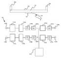
- FIG. 1is a perspective view of an exemplary speaker arrangement in accordance with an embodiment of the invention
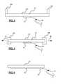
- FIG. 2is a schematic end view of an exemplary speaker system arrangement in accordance with an embodiment of the invention.
- FIG. 3is a schematic end view of an exemplary speaker system arrangement in accordance with another embodiment of the invention.
- FIG. 4is a schematic end view of an exemplary speaker system arrangement in accordance with another embodiment of the invention.
- FIG. 5is a block diagram of an exemplary signal processing system in accordance with one embodiment of the invention.
- FIG. 6is a block diagram of an exemplary amplifier and emitter arrangement in accordance with an embodiment of the invention.
- planate radiating elementis to be understood to refer to a radiating element that is generally planar in nature, but that can vary in a number of manners from a strictly planar object.
- radiating elementscan be substantially flat, rectangular or square elements which include a generally much greater width and height than a thickness.
- Planate radiating elementscan also be curvilinear in nature, for example, they may appear similar in shape to arcuate sections of cylindrical or spherical bodies.
- Planate radiating elementscan include relatively flat surfaces, or they can include ridged, ribbed, textured, or surfaces that otherwise deviate from completely flat.
- the term “substantially”refers to the complete, or nearly complete, extent or degree of an action, characteristic, property, state, structure, item, or result.
- an object that is “substantially” enclosedwould mean that the object is either completely enclosed or nearly completely enclosed.
- the exact allowable degree of deviation from absolute completenessmay in some cases depend on the specific context. However, generally speaking the nearness of completion will be so as to have the same overall result as if absolute and total completion were obtained.
- compositions that is “substantially free of” particleswould either completely lack particles, or so nearly completely lack particles that the effect would be the same as if it completely lacked particles.
- a composition that is “substantially free of” an ingredient or elementmay still actually contain such item as long as there is no measurable effect thereof.
- the term “about”is used to provide flexibility to a numerical range endpoint by providing that a given value may be “a little above” or “a little below” the endpoint.
- a numerical range of “about 1 inch to about 5 inches”should be interpreted to include not only the explicitly recited values of about 1 inch to about 5 inches, but also include individual values and sub-ranges within the indicated range. Thus, included in this numerical range are individual values such as 2, 3, and 4 and sub-ranges such as from 1-3, from 2-4, and from 3-5, etc.
- the speaker 10can include a generally planate radiating member 12 , which can be suitable for radiating ultrasonic vibrations into a fluid medium adjacent the radiating element (e.g., air or other gas or liquid adjacent the unit).
- the systemcan include an emitter 14 that can be predesigned to have an output frequency (and, in some embodiments, a resonant frequency) that is in the ultrasonic audio range.
- the emittercan be intimately coupled to the radiating element in a variety of manners, as will be discussed in further detail below.
- the radiating elementis physically configured to have a mechanical resonance that substantially matches the output or resonant frequency of the emitter.
- a signal processing systemcan be electronically coupled to the emitter 14 via input 15 .
- the signal processing systemwill be suitable to deliver to the emitter an ultrasonic signal (carrier wave) onto which is modulated an audio signal that will be reproduced parametrically in the fluid (e.g., air) adjacent the planate radiator.
- the emitter 14 of the present inventionis not used to emit pressure waves into a fluid medium. Instead, the emitter is intimately bonded to the radiating member 12 and the ultrasonic signal is transmitted into the radiating member.
- the radiating memberwhich can have a mechanical resonance tuned to substantially match the output frequency, and/or the resonant frequency, of the emitter, then radiates pressure waves into the fluid medium adjacent the radiating element. Radiation of the pressure waves by the radiating element results in creation of an audible signal in the fluid medium. Notably, in most cases neither the radiating element nor the emitter produce signals which are audible by the human ear.
- the radiating elementcan be mechanically “tuned” in a variety of manners so as to exhibit a mechanical resonance that substantially matches the output frequency and/or the resonant frequency of the emitter.
- the mechanical resonance of the radiating elementcan be influenced by a number of factors, including, without limitation, material selection, geometry of the radiating element (e.g., thickness, width, height, etc.), surface treatment of the radiating element (e.g., ribbed or otherwise textured surface applied thereto), physically restraining or tensioning the radiating element, etc.
- the radiating elementcan include a body portion (e.g., 24 , 26 in FIGS. 2 and 3 , respectively) and some manner of mechanical stiffening system or mechanism.
- the radiator 12 aincludes a base 24 and a pair of stiffening members 16 a , 16 b coupled to edges of the base to increase a stiffness of the base (and thereby increase the mechanical resonant frequency of the radiator to more closely match that of the emitter).
- FIG. 2shows the stiffening members coupled to or atop side edges of the base, in other embodiments the stiffening members can be coupled along all sides (including the ends) of the base.
- the stiffening memberscan themselves be selected from differing materials, and differing thicknesses, widths, etc. to achieve the desired tuning of the radiating element.
- radiating element 12 bcan include base 26 to which members 18 a and 18 b are coupled.
- Members 18 a , 18 bcan serve as stiffening members in and of themselves, or can serve as elements by which tension can be applied to the base 26 .
- clamps or similar grasping mechanismscan engage members 18 a , 18 b and apply tension by applying force to the members in the directions shown by indicators 28 .
- the radiating element 12 bcan either be fixed in this tensioned state after tensioning (and the mechanical stiffening system can be removed), or it can be held in the tensioned state by the mechanical stiffening system during operation.
- the radiating elementcan be at least partially translucent or transparent.
- the radiating elementcan be formed of a material such a relatively clear polymer or a ceramic glass.
- the radiating elementcan be used as a component of a device in which visual information is provided to a user through the radiating element.
- visual informationFor example, computer display screens, ATM display screens, cell phone screens, etc., can all be provided with a radiating element that is clear enough to allow the user to view visual information presented by the device, while at the same time the radiating element provides highly directional audio information to the user.
- the radiating elementis formed at least partially of an alumino silicate glass.
- an alumino silicate glassOne such material that has been found to be effective is a product sold under the tradename Gorilla Glass. Such a glass is not only very transparent, but is strong and scratch resistant and has the ability to withstand a relatively high degree of tensioning. Thus, in the event the size of the glass selected for a desired application does not possess the desired mechanical resonance, it can be mechanically tuned (e.g., tensioned) until it does.
- the radiating elementcan be formed from a generally sheet-like metallic material, or a variety of polymeric materials, as would be appreciated by one of ordinary skill in the art having possession of this disclosure.
- the emitter 14can be of a variety of types. Suitable examples include, without limitation, piezoelectric emitters, magnetostrictive emitters, and the like. Generally speaking, the emitter must be capable of creating vibrations in the radiating element 12 and so must, typically, include some moveable component that is capable of doing so.
- the emittercan be positioned adjacent the radiating element in a number of places.
- a single emitter 14can be intimately bonded to the radiating element near a center of the radiating element, so as to evenly send vibrations through the entire radiating element.
- a plurality of emitterse.g., 14 a , 14 b , 14 c , 14 d , etc., can be positioned at strategic locations across a surface of the radiating element.
- Various emitter and radiating element pairingswill dictate which relationship is optimal to result in the radiating element radiating the desired ultrasonic pressure waves.
- some degree of transparency or translucencemay be desired in the radiating element.
- the emitter or emitters usedcan be desirable to vary the location of the emitter or emitters used so as to not interfere with the visual effect desired by the emitter system as a whole (e.g., if the radiating element is used as a cell phone “glass,” it may be advantageous to position the emitters out of line of sight of most or all of the input functions in the glass.
- the emittercan be intimately bonded to the radiating element in a number of manners. Suitable ways of bonding the emitter to the radiator include, without limitation, use of adhesives, adhesive tapes, ultrasonic welding (where materials allow), and the like. The choice of which bonding technique (and bonding material) to utilize will often depend upon the type of emitter selected and the material (and surface finish) of the radiating element. It will typically be desired, however, to reduce or limit as much as possible any impedance between the emitter and the bonding material and the radiating element, so as to lose as little power from the signal as is possible.
- the speakercan include a sensing system 20 disposed adjacent the radiating element 12 .
- the sensing systemcan be operable to sense contact with the radiating element by a user to allow the user to input data through the sensing system.
- This aspect of the inventioncan be particularly advantageous for use in devices such as PDAs, cell phones, computer screens, and the like.
- the radiating elementcan simultaneously serve three purposes: it can provide highly directional audio information to the user; it can provide visual information to the user; and it can provide a method by which the user can input data into the device with which the radiating element is associated.
- the sensing system 20can be selected from a variety of such systems known by those of ordinary skill in such arts.
- the present inventionalso provides various methods for arranging, manufacturing or using speakers. These include, without limitation, a method of forming a parametric speaker, including the steps of obtaining a generally planate radiating element and intimately bonding an emitter to the radiating element.
- the emittercan have an ultrasonic output and/or resonant frequency.
- the methodcan include physically altering the radiating element such that it exhibits a mechanical resonance that substantially matches the output and/or resonant frequency of the emitter, if the radiating element does not already exhibit a mechanical resonance that substantially matches the output and/or resonant frequency of the emitter.
- a signal processing systemcan be electronically coupled to the emitter that is suitable for delivering to the emitter a modulated ultrasonic signal carrying an audio signal thereon.
- a method of providing an audible audio signalincluding the steps of obtaining a generally planate radiating element having an emitter intimately bonded thereto, the radiating element having a mechanical resonance that substantially matches an output and/or resonant, ultrasonic frequency of the emitter.
- An ultrasonic signal having an audible signal modulated thereoncan be applied to the emitter to cause the radiating element to radiate the modulated ultrasonic signal to thereby cause an audible difference signal to be produced in a fluid medium adjacent the radiating element.
- FIGS. 5 and 6One an exemplary, non-limiting signal processing system that can be utilized with the present system is illustrated schematically in FIGS. 5 and 6 .
- various processing circuits or componentsare illustrated in the order (relative to the processing path of the signal) in which they are arranged according to one implementation of the invention. It is to be understood that the components of the processing circuit can vary, as can the order in which the input signal is processed by each circuit or component. Also, depending upon the embodiment, the processing system 110 can include more or fewer components or circuits than those shown.
- the example shown in FIG. 5is optimized for use in processing multiple input and output channels (e.g., a “stereo” signal), with various components or circuits including substantially matching components for each channel of the signal. It is to be understood that the system can be equally effectively implemented on a single signal channel (e.g., a “mono” signal), in which case a single channel of components or circuits may be used in place of the multiple channels shown.
- multiple input and output channelse.g., a “stereo” signal
- components or circuitsincluding substantially matching components for each channel of the signal.
- the systemcan be equally effectively implemented on a single signal channel (e.g., a “mono” signal), in which case a single channel of components or circuits may be used in place of the multiple channels shown.
- a multiple channel signal processing system 110can include audio inputs that can correspond to left 112 a and right 112 b channels of an audio input signal.
- Compressor circuits 114 a , 114 bcan compress the dynamic range of the incoming signal, effectively raising the amplitude of certain portions of the incoming signals and lowering the amplitude of certain other portions of the incoming signals resulting in a narrower range of emitted amplitudes.
- the compressorslessen the peak-to-peak amplitude of the input signals by a ratio of not less than about 2:1. Adjusting the input signals to a narrower range of amplitude is important to minimize distortion which is characteristic of the limited dynamic range of this class of modulation systems.
- equalizing networks 116 a , 116 bcan provide equalization of the signal.
- the equalization networkscan advantageously boost lower frequencies to increase the benefit provided naturally by the emitter/inductor combination of the parametric emitter assembly 132 a , 132 b ( FIG. 6 ).
- Low pass filter circuits 118 a , 118 bcan be utilized to provide a hard cutoff of high portions of the signal, with high pass filter circuits 120 a , 120 b providing a hard cutoff of low portions of the audio signals.
- low pass filters 118 a , 118 bare used to cut signals higher than 15 kHz
- high pass filters 120 a , 120 bare used to cut signals lower than 200 Hz (these cutoff points are exemplary and based on a system utilizing an emitter having on the order of 50 square inches of emitter face).
- the high pass filters 120 a , 120 bcan advantageously cut low frequencies that, after modulation, result in nominal deviation of carrier frequency. These low frequencies are very difficult for the system to reproduce efficiently (as a result, much energy can be wasted trying to reproduce these frequencies), and attempting to reproduce them can greatly stress the emitter(s) or radiating element.
- the low pass filtercan advantageously cut higher frequencies that, after modulation, could result in the creation of an audible beat signal with the carrier.
- a low pass filtercuts frequencies above 15 kHz, with a carrier frequency of around 44 kHz, the difference signal will not be lower than around 29 kHz, which is still outside of the audible range for humans.
- frequencies as high as 25 kHzwere allowed to pass the filter circuit, the difference signal generated could be in the range of 19 kHz, which is well within the range of human hearing.
- the audio signalsare modulated by modulators 122 a and 122 b , where they are combined with a carrier signal generated by oscillator 123 .
- a single oscillator(which in one embodiment is driven at a selected frequency of 40 kHz to 50 kHz, which range corresponds to readily available crystals that can be used in the oscillator) is used to drive both modulators 122 a , 122 b .
- an identical carrier frequencyis provided to multiple channels being output at 124 a , 124 b from the modulators. This aspect of the invention can negate the generation of any audible beat frequencies that might otherwise appear between the channels while at the same time reducing overall component count.
- high-pass filters 127 a , 127 bcan be included after modulation that serve to filter out signals below about 25 kHz. In this manner, the system can ensure that no audible frequencies enter the amplifier via outputs 124 a , 124 b . In this manner, only the modulated carrier wave is fed to the amplifier(s), with any audio artifacts being removed prior to the signal being fed to the amplifier(s).
- the signal processing system 10receives audio input at 112 a , 112 b and processes these signals prior to feeding them to modulators 122 a , 122 b .
- An oscillating signalis provided at 123 , with the resultant outputs at 124 a , 124 b then including both a carrier (typically ultrasonic) wave and the audio signals that are being reproduced, typically modulated onto the carrier wave.
- the resulting signal(s)once emitted in a non-linear medium such as air, produce highly directional parametric sound within the non-linear medium.
Landscapes
- Engineering & Computer Science (AREA)
- Physics & Mathematics (AREA)
- Acoustics & Sound (AREA)
- Signal Processing (AREA)
- Multimedia (AREA)
- Circuit For Audible Band Transducer (AREA)
Abstract
Description
Claims (19)
Priority Applications (2)
| Application Number | Priority Date | Filing Date | Title |
|---|---|---|---|
| US13/801,718US8983098B2 (en) | 2012-08-14 | 2013-03-13 | Substantially planate parametric emitter and associated methods |
| PCT/US2014/018654WO2014163894A2 (en) | 2013-03-13 | 2014-02-26 | Substantially planate parametric emitter and associated methods |
Applications Claiming Priority (2)
| Application Number | Priority Date | Filing Date | Title |
|---|---|---|---|
| US201261682959P | 2012-08-14 | 2012-08-14 | |
| US13/801,718US8983098B2 (en) | 2012-08-14 | 2013-03-13 | Substantially planate parametric emitter and associated methods |
Publications (2)
| Publication Number | Publication Date |
|---|---|
| US20140161282A1 US20140161282A1 (en) | 2014-06-12 |
| US8983098B2true US8983098B2 (en) | 2015-03-17 |
Family
ID=50880992
Family Applications (1)
| Application Number | Title | Priority Date | Filing Date |
|---|---|---|---|
| US13/801,718ActiveUS8983098B2 (en) | 2012-08-14 | 2013-03-13 | Substantially planate parametric emitter and associated methods |
Country Status (2)
| Country | Link |
|---|---|
| US (1) | US8983098B2 (en) |
| WO (1) | WO2014163894A2 (en) |
Cited By (9)
| Publication number | Priority date | Publication date | Assignee | Title |
|---|---|---|---|---|
| US20140269207A1 (en)* | 2013-03-15 | 2014-09-18 | Elwha Llc | Portable Electronic Device Directed Audio Targeted User System and Method |
| US20140269196A1 (en)* | 2013-03-15 | 2014-09-18 | Elwha Llc | Portable Electronic Device Directed Audio Emitter Arrangement System and Method |
| US9332344B2 (en) | 2013-06-13 | 2016-05-03 | Turtle Beach Corporation | Self-bias emitter circuit |
| US20160227329A1 (en)* | 2015-01-15 | 2016-08-04 | Frank Joseph Pompei | Modulation systems and methods for parametric loudspeaker systems |
| US10181314B2 (en) | 2013-03-15 | 2019-01-15 | Elwha Llc | Portable electronic device directed audio targeted multiple user system and method |
| US10291983B2 (en) | 2013-03-15 | 2019-05-14 | Elwha Llc | Portable electronic device directed audio system and method |
| US10531190B2 (en) | 2013-03-15 | 2020-01-07 | Elwha Llc | Portable electronic device directed audio system and method |
| US10575093B2 (en) | 2013-03-15 | 2020-02-25 | Elwha Llc | Portable electronic device directed audio emitter arrangement system and method |
| US11167375B2 (en) | 2018-08-10 | 2021-11-09 | The Research Foundation For The State University Of New York | Additive manufacturing processes and additively manufactured products |
Families Citing this family (7)
| Publication number | Priority date | Publication date | Assignee | Title |
|---|---|---|---|---|
| EP2580922B1 (en) | 2010-06-14 | 2019-03-20 | Turtle Beach Corporation | Improved parametric signal processing and emitter systems and related methods |
| US9036831B2 (en) | 2012-01-10 | 2015-05-19 | Turtle Beach Corporation | Amplification system, carrier tracking systems and related methods for use in parametric sound systems |
| US8958580B2 (en) | 2012-04-18 | 2015-02-17 | Turtle Beach Corporation | Parametric transducers and related methods |
| US8934650B1 (en) | 2012-07-03 | 2015-01-13 | Turtle Beach Corporation | Low profile parametric transducers and related methods |
| US8903104B2 (en) | 2013-04-16 | 2014-12-02 | Turtle Beach Corporation | Video gaming system with ultrasonic speakers |
| US8988911B2 (en) | 2013-06-13 | 2015-03-24 | Turtle Beach Corporation | Self-bias emitter circuit |
| CN110521217B (en) | 2017-03-29 | 2021-10-19 | Agc株式会社 | glass plate structure |
Citations (20)
| Publication number | Priority date | Publication date | Assignee | Title |
|---|---|---|---|---|
| WO1997009842A2 (en) | 1995-09-02 | 1997-03-13 | New Transducers Limited | Acoustic device |
| US5889870A (en)* | 1996-07-17 | 1999-03-30 | American Technology Corporation | Acoustic heterodyne device and method |
| US6108433A (en)* | 1998-01-13 | 2000-08-22 | American Technology Corporation | Method and apparatus for a magnetically induced speaker diaphragm |
| US6229899B1 (en)* | 1996-07-17 | 2001-05-08 | American Technology Corporation | Method and device for developing a virtual speaker distant from the sound source |
| US6278787B1 (en) | 1996-09-03 | 2001-08-21 | New Transducers Limited | Loudspeakers |
| US6372066B1 (en) | 1999-05-06 | 2002-04-16 | New Transducers Limited | Vibration exciter |
| US6546106B2 (en) | 1996-09-03 | 2003-04-08 | New Transducers Limited | Acoustic device |
| US6606390B2 (en) | 1996-09-03 | 2003-08-12 | New Transducer Limited | Loudspeakers |
| US6606389B1 (en)* | 1997-03-17 | 2003-08-12 | American Technology Corporation | Piezoelectric film sonic emitter |
| US6865277B2 (en) | 2000-01-27 | 2005-03-08 | New Transducers Limited | Passenger vehicle |
| US6871149B2 (en) | 2002-12-06 | 2005-03-22 | New Transducers Limited | Contact sensitive device |
| US6885753B2 (en) | 2000-01-27 | 2005-04-26 | New Transducers Limited | Communication device using bone conduction |
| US20050100181A1 (en) | 1998-09-24 | 2005-05-12 | Particle Measuring Systems, Inc. | Parametric transducer having an emitter film |
| US6922642B2 (en) | 2001-07-04 | 2005-07-26 | New Transducers Limited | Contact sensitive device |
| US6925187B2 (en)* | 2000-03-28 | 2005-08-02 | American Technology Corporation | Horn array emitter |
| US6965678B2 (en) | 2000-01-27 | 2005-11-15 | New Transducers Limited | Electronic article comprising loudspeaker and touch pad |
| US7149318B2 (en) | 2000-01-24 | 2006-12-12 | New Transducers Limited | Resonant element transducer |
| US7151837B2 (en) | 2000-01-27 | 2006-12-19 | New Transducers Limited | Loudspeaker |
| US7157649B2 (en) | 1999-12-23 | 2007-01-02 | New Transducers Limited | Contact sensitive device |
| US7635941B2 (en) | 2002-05-20 | 2009-12-22 | New Transducers Limited | Transducer |
Family Cites Families (4)
| Publication number | Priority date | Publication date | Assignee | Title |
|---|---|---|---|---|
| IL136820A0 (en)* | 1998-01-20 | 2001-06-14 | New Transducers Ltd | Active acoustic devices comprising panel members |
| JP2000050387A (en)* | 1998-07-16 | 2000-02-18 | Massachusetts Inst Of Technol <Mit> | Parametric audio system |
| US8797721B2 (en)* | 2010-02-02 | 2014-08-05 | Apple Inc. | Portable electronic device housing with outer glass surfaces |
| EP2580922B1 (en)* | 2010-06-14 | 2019-03-20 | Turtle Beach Corporation | Improved parametric signal processing and emitter systems and related methods |
- 2013
- 2013-03-13USUS13/801,718patent/US8983098B2/enactiveActive
- 2014
- 2014-02-26WOPCT/US2014/018654patent/WO2014163894A2/enactiveApplication Filing
Patent Citations (23)
| Publication number | Priority date | Publication date | Assignee | Title |
|---|---|---|---|---|
| WO1997009842A2 (en) | 1995-09-02 | 1997-03-13 | New Transducers Limited | Acoustic device |
| US6229899B1 (en)* | 1996-07-17 | 2001-05-08 | American Technology Corporation | Method and device for developing a virtual speaker distant from the sound source |
| US5889870A (en)* | 1996-07-17 | 1999-03-30 | American Technology Corporation | Acoustic heterodyne device and method |
| US6546106B2 (en) | 1996-09-03 | 2003-04-08 | New Transducers Limited | Acoustic device |
| US6278787B1 (en) | 1996-09-03 | 2001-08-21 | New Transducers Limited | Loudspeakers |
| US6606390B2 (en) | 1996-09-03 | 2003-08-12 | New Transducer Limited | Loudspeakers |
| US6606389B1 (en)* | 1997-03-17 | 2003-08-12 | American Technology Corporation | Piezoelectric film sonic emitter |
| US6108433A (en)* | 1998-01-13 | 2000-08-22 | American Technology Corporation | Method and apparatus for a magnetically induced speaker diaphragm |
| US20050100181A1 (en) | 1998-09-24 | 2005-05-12 | Particle Measuring Systems, Inc. | Parametric transducer having an emitter film |
| US6372066B1 (en) | 1999-05-06 | 2002-04-16 | New Transducers Limited | Vibration exciter |
| US7157649B2 (en) | 1999-12-23 | 2007-01-02 | New Transducers Limited | Contact sensitive device |
| US7684576B2 (en) | 2000-01-24 | 2010-03-23 | New Transducers Limited | Resonant element transducer |
| US7149318B2 (en) | 2000-01-24 | 2006-12-12 | New Transducers Limited | Resonant element transducer |
| US6965678B2 (en) | 2000-01-27 | 2005-11-15 | New Transducers Limited | Electronic article comprising loudspeaker and touch pad |
| US6885753B2 (en) | 2000-01-27 | 2005-04-26 | New Transducers Limited | Communication device using bone conduction |
| US7151837B2 (en) | 2000-01-27 | 2006-12-19 | New Transducers Limited | Loudspeaker |
| US6865277B2 (en) | 2000-01-27 | 2005-03-08 | New Transducers Limited | Passenger vehicle |
| US6925187B2 (en)* | 2000-03-28 | 2005-08-02 | American Technology Corporation | Horn array emitter |
| US6922642B2 (en) | 2001-07-04 | 2005-07-26 | New Transducers Limited | Contact sensitive device |
| US7635941B2 (en) | 2002-05-20 | 2009-12-22 | New Transducers Limited | Transducer |
| US6871149B2 (en) | 2002-12-06 | 2005-03-22 | New Transducers Limited | Contact sensitive device |
| US7184898B2 (en) | 2002-12-06 | 2007-02-27 | New Transducers Limited | Contact sensitive device |
| US7376523B2 (en) | 2002-12-06 | 2008-05-20 | New Transducers Limited | Contact sensitive device |
Cited By (12)
| Publication number | Priority date | Publication date | Assignee | Title |
|---|---|---|---|---|
| US20140269207A1 (en)* | 2013-03-15 | 2014-09-18 | Elwha Llc | Portable Electronic Device Directed Audio Targeted User System and Method |
| US20140269196A1 (en)* | 2013-03-15 | 2014-09-18 | Elwha Llc | Portable Electronic Device Directed Audio Emitter Arrangement System and Method |
| US10181314B2 (en) | 2013-03-15 | 2019-01-15 | Elwha Llc | Portable electronic device directed audio targeted multiple user system and method |
| US10291983B2 (en) | 2013-03-15 | 2019-05-14 | Elwha Llc | Portable electronic device directed audio system and method |
| US10531190B2 (en) | 2013-03-15 | 2020-01-07 | Elwha Llc | Portable electronic device directed audio system and method |
| US10575093B2 (en) | 2013-03-15 | 2020-02-25 | Elwha Llc | Portable electronic device directed audio emitter arrangement system and method |
| US9332344B2 (en) | 2013-06-13 | 2016-05-03 | Turtle Beach Corporation | Self-bias emitter circuit |
| US20160227329A1 (en)* | 2015-01-15 | 2016-08-04 | Frank Joseph Pompei | Modulation systems and methods for parametric loudspeaker systems |
| US9681225B2 (en)* | 2015-01-15 | 2017-06-13 | Frank Joseph Pompei | Modulation systems and methods for parametric loudspeaker systems |
| US11167375B2 (en) | 2018-08-10 | 2021-11-09 | The Research Foundation For The State University Of New York | Additive manufacturing processes and additively manufactured products |
| US11426818B2 (en) | 2018-08-10 | 2022-08-30 | The Research Foundation for the State University | Additive manufacturing processes and additively manufactured products |
| US12122120B2 (en) | 2018-08-10 | 2024-10-22 | The Research Foundation For The State University Of New York | Additive manufacturing processes and additively manufactured products |
Also Published As
| Publication number | Publication date |
|---|---|
| WO2014163894A2 (en) | 2014-10-09 |
| US20140161282A1 (en) | 2014-06-12 |
| WO2014163894A3 (en) | 2015-10-29 |
Similar Documents
| Publication | Publication Date | Title |
|---|---|---|
| US8983098B2 (en) | Substantially planate parametric emitter and associated methods | |
| US8958580B2 (en) | Parametric transducers and related methods | |
| US20040052387A1 (en) | Piezoelectric film emitter configuration | |
| EP2597892A1 (en) | Vibration device | |
| US8903116B2 (en) | Parametric transducers and related methods | |
| CN101262712A (en) | A voice directional spreading sound system | |
| WO2003032678A2 (en) | Ultrasonic transducer for parametric array | |
| CN102986249A (en) | Vibration device and electronic device | |
| CA2536390A1 (en) | Parametric tranducer having an emitter film | |
| US11076242B2 (en) | Ultrasonic transducer | |
| KR20020079767A (en) | Piezoelectric film sonic emitter | |
| KR101809714B1 (en) | Piezoelectric transducer including the piezoelectric unit and directive speaker including the transducer | |
| CN104918193A (en) | Piezoelectric electroacoustic transducer | |
| US5325439A (en) | Loudspeaker apparatus | |
| CN114173261B (en) | Ultrasonic sound generator, display and electronic equipment | |
| US20060233404A1 (en) | Horn array emitter | |
| CN103262575A (en) | Oscillator device and electronic instrument | |
| KR101386009B1 (en) | Ultrasonic transducer for super-directional speaker and method for manufacturing the same | |
| KR101765006B1 (en) | Piezoelectric transducer for a directive speaker and directive speaker including the transducer | |
| JP2009118093A (en) | Electrostatic transducer and ultrasonic speaker | |
| JP2009038637A (en) | Electrostatic speaker | |
| US11837213B2 (en) | Ultrasonic transducer with perforated baseplate | |
| EP2590435A1 (en) | Vibration device | |
| Kuroda et al. | Design of an ultrasonic piezoelectric transducer having double-linked diaphragms for parametric speakers | |
| WO2018079583A1 (en) | Electroacoustic transducer and electroacoustic transducer device |
Legal Events
| Date | Code | Title | Description |
|---|---|---|---|
| AS | Assignment | Owner name:PARAMETRIC SOUND CORPORATION, CALIFORNIA Free format text:ASSIGNMENT OF ASSIGNORS INTEREST;ASSIGNOR:NORRIS, ELWOOD G.;REEL/FRAME:030267/0124 Effective date:20130404 | |
| AS | Assignment | Owner name:TURTLE BEACH CORPORATION, CALIFORNIA Free format text:CHANGE OF NAME;ASSIGNOR:PARAMETRIC SOUND CORPORATION;REEL/FRAME:033868/0840 Effective date:20140520 | |
| STCF | Information on status: patent grant | Free format text:PATENTED CASE | |
| AS | Assignment | Owner name:CRYSTAL FINANCIAL LLC, AS AGENT, MASSACHUSETTS Free format text:SECURITY INTEREST;ASSIGNOR:TURTLE BEACH CORPORATION;REEL/FRAME:036159/0952 Effective date:20150722 | |
| AS | Assignment | Owner name:BANK OF AMERICA, N.A., AS AGENT, CALIFORNIA Free format text:SECURITY INTEREST;ASSIGNORS:TURTLE BEACH CORPORATION;VOYETRA TURTLE BEACH, INC.;REEL/FRAME:036189/0326 Effective date:20150722 | |
| AS | Assignment | Owner name:CRYSTAL FINANCIAL LLC, AS AGENT, MASSACHUSETTS Free format text:SECURITY INTEREST;ASSIGNOR:TURTLE BEACH CORPORATION;REEL/FRAME:045573/0722 Effective date:20180305 | |
| AS | Assignment | Owner name:BANK OF AMERICA, N.A., AS AGENT, CALIFORNIA Free format text:SECURITY INTEREST;ASSIGNORS:TURTLE BEACH CORPORATION;VOYETRA TURTLE BEACH, INC.;REEL/FRAME:045776/0648 Effective date:20180305 | |
| MAFP | Maintenance fee payment | Free format text:PAYMENT OF MAINTENANCE FEE, 4TH YR, SMALL ENTITY (ORIGINAL EVENT CODE: M2551); ENTITY STATUS OF PATENT OWNER: SMALL ENTITY Year of fee payment:4 | |
| AS | Assignment | Owner name:TURTLE BEACH CORPORATION, CALIFORNIA Free format text:TERMINATION AND RELEASE OF INTELLECTUAL PROPERTY SECURITY AGREEMENTS;ASSIGNOR:CRYSTAL FINANCIAL LLC;REEL/FRAME:048965/0001 Effective date:20181217 Owner name:TURTLE BEACH CORPORATION, CALIFORNIA Free format text:TERMINATION AND RELEASE OF INTELLECTUAL PROPERTY SECURITY AGREEMENTS;ASSIGNOR:CRYSTAL FINANCIAL LLC;REEL/FRAME:047954/0007 Effective date:20181217 | |
| MAFP | Maintenance fee payment | Free format text:PAYMENT OF MAINTENANCE FEE, 8TH YR, SMALL ENTITY (ORIGINAL EVENT CODE: M2552); ENTITY STATUS OF PATENT OWNER: SMALL ENTITY Year of fee payment:8 | |
| AS | Assignment | Owner name:BLUE TORCH FINANCE LLC, AS THE COLLATERAL AGENT, NEW YORK Free format text:SECURITY INTEREST;ASSIGNORS:VOYETRA TURTLE BEACH, INC.;TURTLE BEACH CORPORATION;PERFORMANCE DESIGNED PRODUCTS LLC;REEL/FRAME:066797/0517 Effective date:20240313 | |
| AS | Assignment | Owner name:TURTLE BEACH CORPORATION, CALIFORNIA Free format text:RELEASE BY SECURED PARTY;ASSIGNOR:BLUE TORCH FINANCE LLC, AS THE COLLATERAL AGENT;REEL/FRAME:072337/0391 Effective date:20250801 Owner name:VOYETRA TURTLE BEACH, INC., CALIFORNIA Free format text:RELEASE BY SECURED PARTY;ASSIGNOR:BLUE TORCH FINANCE LLC, AS THE COLLATERAL AGENT;REEL/FRAME:072337/0391 Effective date:20250801 Owner name:PERFORMANCE DESIGNED PRODUCTS LLC, CALIFORNIA Free format text:RELEASE BY SECURED PARTY;ASSIGNOR:BLUE TORCH FINANCE LLC, AS THE COLLATERAL AGENT;REEL/FRAME:072337/0391 Effective date:20250801 | |
| AS | Assignment | Owner name:BANK OF AMERICA, N.A., AS ADMINISTRATIVE AGENT, NORTH CAROLINA Free format text:ASSIGNMENT OF SECURITY AGREEMENT;ASSIGNORS:TURTLE BEACH CORPORATION;VOYETRA TURTLE BEACH, INC.;PERFORMANCE DESIGNED PRODUCTS LLC;REEL/FRAME:072338/0059 Effective date:20250801 |