US8982933B2 - Communications system including jammer using continuous phase modulation (CPM) and associated methods - Google Patents
Communications system including jammer using continuous phase modulation (CPM) and associated methodsDownload PDFInfo
- Publication number
- US8982933B2 US8982933B2US13/169,347US201113169347AUS8982933B2US 8982933 B2US8982933 B2US 8982933B2US 201113169347 AUS201113169347 AUS 201113169347AUS 8982933 B2US8982933 B2US 8982933B2
- Authority
- US
- United States
- Prior art keywords
- jammer
- interfering
- signal
- controller
- receiver
- Prior art date
- Legal status (The legal status is an assumption and is not a legal conclusion. Google has not performed a legal analysis and makes no representation as to the accuracy of the status listed.)
- Active, expires
Links
- 238000000034methodMethods0.000titleclaimsdescription20
- 230000002452interceptive effectEffects0.000claimsabstractdescription67
- 230000008901benefitEffects0.000description3
- 238000011161developmentMethods0.000description2
- 238000010586diagramMethods0.000description2
- 238000012986modificationMethods0.000description2
- 230000004048modificationEffects0.000description2
- 238000001228spectrumMethods0.000description2
- 238000003491arrayMethods0.000description1
- 230000005540biological transmissionEffects0.000description1
- 230000015572biosynthetic processEffects0.000description1
- 239000000969carrierSubstances0.000description1
- 238000005516engineering processMethods0.000description1
- 238000012544monitoring processMethods0.000description1
- 230000000135prohibitive effectEffects0.000description1
- 230000001172regenerating effectEffects0.000description1
- 230000004044responseEffects0.000description1
Images


Classifications
- G—PHYSICS
- G01—MEASURING; TESTING
- G01S—RADIO DIRECTION-FINDING; RADIO NAVIGATION; DETERMINING DISTANCE OR VELOCITY BY USE OF RADIO WAVES; LOCATING OR PRESENCE-DETECTING BY USE OF THE REFLECTION OR RERADIATION OF RADIO WAVES; ANALOGOUS ARRANGEMENTS USING OTHER WAVES
- G01S7/00—Details of systems according to groups G01S13/00, G01S15/00, G01S17/00
- G01S7/02—Details of systems according to groups G01S13/00, G01S15/00, G01S17/00 of systems according to group G01S13/00
- G01S7/38—Jamming means, e.g. producing false echoes
- H—ELECTRICITY
- H04—ELECTRIC COMMUNICATION TECHNIQUE
- H04K—SECRET COMMUNICATION; JAMMING OF COMMUNICATION
- H04K3/00—Jamming of communication; Counter-measures
- H04K3/40—Jamming having variable characteristics
- H04K3/44—Jamming having variable characteristics characterized by the control of the jamming waveform or modulation type
- H—ELECTRICITY
- H04—ELECTRIC COMMUNICATION TECHNIQUE
- H04K—SECRET COMMUNICATION; JAMMING OF COMMUNICATION
- H04K3/00—Jamming of communication; Counter-measures
- H04K3/40—Jamming having variable characteristics
- H04K3/45—Jamming having variable characteristics characterized by including monitoring of the target or target signal, e.g. in reactive jammers or follower jammers for example by means of an alternation of jamming phases and monitoring phases, called "look-through mode"
Definitions
- the present inventionrelates to the field of communications systems, and more particularly, to communications systems including jammers that use continuous phase modulation and similar modulation schemes.
- Jammingis usually achieved by transmitting a jamming signal at a same frequency or in a same frequency band as that used by the intended signal.
- the jamming signalmay block a single frequency, identified as “spot jamming,” or may block a band of frequencies, identified as “barrage jamming.”
- barrage jammersare typically either barrage jammers broadcasting broadband noise or continuous wave (CW) signals targeted at specific known intended signals.
- barrage jammerstend to produce a low energy density in any given communications channel, for example a 25 kHz channel, when jamming a broad band of channels.
- CWcontinuous wave
- a 200 MHz barrage jammer transmitting 100 Wattsgenerally will have 12 mWatts in any communications channel and this low power level per channel is likely to be ineffective as a jammer.
- jammersalso tend to jam wanted communications.
- a common jammer techniqueis to capture an individual local transmitter signal for a short period of time, copy the captured signal as a regenerated signal and retransmit that regenerated signal a short period of time later.
- Such a “regenerative” jammercreates false radar targets that appear as real targets thereby confusing the radar local receivers.
- a jammeruses time-division multiplexing techniques that permit monitoring received RF local transmitter signals while, in a time-division multiplexing sense, concurrently transmitting RF signals to jam selected transmissions at local receivers.
- the time-division multiplexingalternately enables the jamming system receiver and transmitter with operation at a frequency higher than the Nyquist rate. The precision required in the receiver of such a jammer may be cost prohibitive, however.
- FMfrequency modulated
- AMamplitude modulated
- pulse modulated signalspulse modulated signals
- FFTFast Fourier Transform
- FPGAsfield programmable gate arrays
- a communications systemincluding a jammer configured to jam a target receiver from receiving an intended signal.
- a communications systemmay comprise a target receiver having a passband and configured to receive an intended signal within the passband, and a jammer configured to jam the target receiver from receiving the intended signal.
- the jammermay comprise at least one antenna, a jammer receiver coupled to the at least one antenna, a jammer transmitter coupled to the at least one antenna, and a controller.
- the controllermay be configured to cooperate with the jammer receiver to detect the intended signal, and may also cooperate with the jammer transmitter to transmit an interfering signal comprising a continuous phase modulation (CPM) waveform having a constant envelope so that the interfering signal at least overlaps the intended signal.
- CCMcontinuous phase modulation
- This communications systemallows for a simpler jammer receiver than is typically used in the prior art, and provides better performance while avoiding jamming desired communications channels.
- the interfering signalmay include at least one interfering tone within the passband of the target receiver.
- the target receivermay be configured to receive the interfering signal and decode at least one interfering symbol from the at least one interfering tone.
- the controllermay be configured to selectively transmit the at least one interfering tone as an FM tone. Additionally or alternatively, the controller may be configured to transmit the at least one interfering tone as a plurality of interfering tones. Furthermore, the controller may be configured to transmit the continuous phase waveform over a selectable bandwidth.
- the controllermay be configured to detect the intended signal by performing a Fast Fourier Transform (FFT).
- the controllermay be configured to transmit the interfering signal by transmitting a continuous phase waveform with phase memory having a phase trellis structure, and adding at least one phase pulse to the phase trellis structure.
- the controllermay be configured to generate the phase pulse as a plurality of pseudo-orthogonal phase pulses.
- a method aspectis directed to a method of operating a jammer to jamming a target receiver having a passband and being configured to receive a intended signal within the passband, the jammer comprising at least one antenna, a jammer receiver coupled to the at least one antenna, a jammer transmitter coupled to the at least one antenna, and a controller configured to cooperate with the jammer receiver.
- the methodmay include detecting the intended signal, using the controller in cooperation with the jammer receiver.
- the methodmay further include generating an interfering signal comprising a continuous phase modulation (CPM) waveform having a constant envelope so that the interfering signal at least overlaps the intended signal, using the controller in cooperation with the jammer transmitter.
- CCMcontinuous phase modulation
- FIG. 1is a schematic block diagram of a communications system in accordance with the present invention.
- FIG. 2is a more detailed block diagram of a communications system in accordance with the present invention.
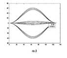
- FIG. 3is a graph of an interfering signal generated by the jammer of FIG. 2 showing the phase trellis structure.
- FIG. 4is another graph of the interfering signal generated by the jammer of FIG. 2
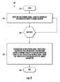
- FIG. 5is a method of operating the jammer of FIG. 1 .
- the communications system 20includes a target receiver 22 and a jammer 24 .
- An intended signal source 23transmits an intended signal.
- the target receiver 22has a passband, and is configured to receive the intended signal within the passband.
- the target receiver 22may be a typical receiver known to those of skill in the art, operating at suitable frequencies, and according to suitable modulation schemes, such as FM, AM, and pulse modulation. Therefore, specifics of the target receiver 22 need not be addressed herein.
- the jammer 24includes at least one antenna 26 coupled to a jammer receiver 28 and a jammer transmitter 30 .
- the jammer receiver 28 and jammer transmitter 30are each coupled to a controller 32 .
- the controller 32is configured to cooperate with the jammer receiver 28 to detect the intended signal.
- the controller 32is further configured to cooperate with the jammer transmitter 30 to generate an interfering signal comprising a continuous phase modulation (CPM) waveform having a constant envelope so that the interfering signal at least partially overlaps the passband of the target receiver.
- CCMcontinuous phase modulation
- This interfering signalmay have a greater transmitted power than the intended signal, and therefore the target receiver 22 may receive the interfering signal instead of the intended signal. Therefore, the interfering signal “jams” the target receiver 22 from receiving the intended signal.
- the CPM waveformis a constant envelope modulation that provides an inherent phase and frequency diversity which has some similar properties to the standard spread-spectrum modulation.
- the CPM equationstarts with:
- Ethe symbol energy
- Tthe symbol time
- fthe carrier frequency
- ⁇ iare M-ary data symbols taken from the alphabet ⁇ +/ ⁇ 1, +/ ⁇ 3, . . .
- q n ( t )( ⁇ 1) n r c , with 0 ⁇ t ⁇ T/ 2
- q n ( t )( ⁇ 1) n +(1 ⁇ ( ⁇ 1) n ) r c , with T/ 2 ⁇ t ⁇ T where r c is defined as (1 ⁇ cos(( ⁇ /2)(t/T))/2, with 0 ⁇ t ⁇ T.
- the controller 32 ′cooperates with the jammer receiver 28 ′ to detect the intended signal by performing a Fast Fourier Transform (FFT).
- the controller 32 ′may cooperate with the jammer transmitter 30 ′ to generate the CPM waveform to have at least one interfering tone within the passband.
- the interfering tonemay be generated as an FM tone or other tone, for example.
- the target receiver 22 ′receives the interfering signal, it then decodes at least one interfering symbol from the at least one interfering tone.
- a particularly advantageous property of the interfering signalis that the at least one tone may be decoded into at least one interfering symbol, thereby avoiding attenuation by filters in the target receiver 22 ′ that might otherwise defeat an interfering signal that acts as noise and may not be decoded into at least one interfering symbol.
- the CPM waveformmay have a phase memory with a phase trellis structure, and at least one phase pulse may be added to the phase trellis structure.
- the phase pulsemay be a plurality of pseudo-orthogonal phase pulses, for example. Any phase pulse can be used as long as the start and end position of phase pulses is the same (or modulo 2PI), as will be appreciated by those of skill in the art.
- An example CPM waveform with the phase trellis structure and having 64 phase pulsesis shown in FIG. 3 .
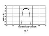
- Another example CPM waveformis shown in FIG. 5 .
- the interfering signalmay include a plurality of interfering tones and that the number of interfering tones in the interfering signal may be selectable based upon an input device coupled to the controller 32 ′. Similarly, the interfering signal may be generated over a bandwidth selectable based upon an input device.
- the controller 32 ′ and jammer transmitter 30 ′adjust the bandwidth by increasing the number of phase pulses added to the phase trellis structure (e.g. 128 phase pulses, 256 phase pulses, 512 phase pulses).
- the bandwidthmay also be adjusted by increasing the number of data signals (e.g. going from a 4-ary system to a 16-ary system).
- the number of data signalsmay be increased without the formation of such undesirable side lobes.
- Another advantage of the interfering signal generated by the jammer 24 ′is that, due to the adjustability of the bandwidth, the FFT performed need not be a high resolution FFT. Consequently, the circuitry in the jammer receiver 28 ′ that performs the FFT, which is preferably a field programmable gate array (FPGA), can be simpler than that used in prior art jammer receivers, thereby saving power and reducing the cost of the jammer 24 ′.
- FPGAfield programmable gate array
- the methodincludes detecting the intended signal, using the controller in cooperation with the jammer receiver (Block 104 ).
- Block 105if the intended signal is detected, the method proceeds to Block 106 , and therefore includes transmitting an interfering signal comprising a continuous phase modulation (CPM) waveform having a constant envelope so that the interfering signal at least overlaps the intended signal, using the controller in cooperation with the jammer transmitter (Block 106 ). If the intended signal is not detected, then, at Block 105 , the method returns to detecting at Block 104 . Block 108 indicates the end of the method.
- CCMcontinuous phase modulation
Landscapes
- Engineering & Computer Science (AREA)
- Computer Networks & Wireless Communication (AREA)
- Signal Processing (AREA)
- Physics & Mathematics (AREA)
- General Physics & Mathematics (AREA)
- Radar, Positioning & Navigation (AREA)
- Remote Sensing (AREA)
- Noise Elimination (AREA)
Abstract
Description
where E is the symbol energy, T is the symbol time, f is the carrier frequency, αiare M-ary data symbols taken from the alphabet {+/−1, +/−3, . . . , (M−1)}, M being an even number, hi is a modulation index, q(t) is the phase response and is normalized such that q(t)=0 for t≦0 q(t)=½ for t≧LT, L being the memory of the CPM modulation scheme. In addition:
qn(t)=(−1)nrc, with 0<t≦T/2
qn(t)=(−1)n+(1−(−1)n)rc, withT/2<t≦T
where rcis defined as (1−cos((π/2)(t/T))/2, with 0<t≦T.
Claims (21)
Priority Applications (1)
| Application Number | Priority Date | Filing Date | Title |
|---|---|---|---|
| US13/169,347US8982933B2 (en) | 2011-06-27 | 2011-06-27 | Communications system including jammer using continuous phase modulation (CPM) and associated methods |
Applications Claiming Priority (1)
| Application Number | Priority Date | Filing Date | Title |
|---|---|---|---|
| US13/169,347US8982933B2 (en) | 2011-06-27 | 2011-06-27 | Communications system including jammer using continuous phase modulation (CPM) and associated methods |
Publications (2)
| Publication Number | Publication Date |
|---|---|
| US20120327985A1 US20120327985A1 (en) | 2012-12-27 |
| US8982933B2true US8982933B2 (en) | 2015-03-17 |
Family
ID=47361829
Family Applications (1)
| Application Number | Title | Priority Date | Filing Date |
|---|---|---|---|
| US13/169,347Active2032-03-30US8982933B2 (en) | 2011-06-27 | 2011-06-27 | Communications system including jammer using continuous phase modulation (CPM) and associated methods |
Country Status (1)
| Country | Link |
|---|---|
| US (1) | US8982933B2 (en) |
Families Citing this family (4)
| Publication number | Priority date | Publication date | Assignee | Title |
|---|---|---|---|---|
| US8604965B2 (en)* | 2010-02-26 | 2013-12-10 | Federal Aviation Administration/Department of Transportation | Apparatus and method to generate and detect virtual targets |
| EP3174230B1 (en)* | 2014-07-22 | 2022-03-30 | Nec Corporation | Radio wave interference system, radio wave interference apparatus, and radio wave interference method |
| FR3047566B1 (en)* | 2016-02-05 | 2020-03-06 | Thales | METHOD OF INTERFERING RADARS OF THE SYNTHETIC OPENING TYPE AND ASSOCIATED DEVICE |
| CN112203350B (en)* | 2019-06-19 | 2024-04-12 | 华为技术有限公司 | Signal sending method and device |
Citations (14)
| Publication number | Priority date | Publication date | Assignee | Title |
|---|---|---|---|---|
| US5832022A (en)* | 1995-06-02 | 1998-11-03 | Omnipoint Corporation | Method and apparatus for controlling the modulation index of continuous phase modulated (CPM) signals |
| US6476755B1 (en)* | 1980-04-28 | 2002-11-05 | Bae Systems Information And Electronic Systems Integration Inc. | Communications jamming receiver |
| US6834073B1 (en)* | 2000-05-26 | 2004-12-21 | Freescale Semiconductor, Inc. | System and method for baseband removal of narrowband interference in ultra wideband signals |
| US20050181823A1 (en)* | 2004-02-12 | 2005-08-18 | Haartsen Jacobus C. | Coexistence of multiple radio systems in unlicensed bands |
| US20060098753A1 (en)* | 2004-11-05 | 2006-05-11 | Harris Corporation | Continuous phase modulation system and method with added phase pulse |
| US7072414B1 (en)* | 1999-09-07 | 2006-07-04 | The Aerospace Corporation | Gaussian minimum shift keying (GMSK) precoding communication method |
| US20080123578A1 (en)* | 2002-11-07 | 2008-05-29 | Matsushita Electric Industrial Co., Ltd. | Method Of Determining Feedback In A Communication System |
| US20080191924A1 (en)* | 2005-01-26 | 2008-08-14 | Duff William G | Method and apparatus for protecting personnel and materiel from rf-based threats using ultra-wideband (uwb) transmission |
| US20090061759A1 (en)* | 2006-03-24 | 2009-03-05 | Robert Eugene Stoddard | Regenerative jammer with multiple jamming algorithms |
| US20090279422A1 (en)* | 2005-10-20 | 2009-11-12 | Trellis Phase Communications, Lp | Single sideband and quadrature multiplexed continuous phase modulation |
| US7728755B1 (en)* | 2005-03-16 | 2010-06-01 | Damjan Jocic | Reactive parallel processing jamming system |
| US20110223851A1 (en)* | 2006-09-15 | 2011-09-15 | Robert Eugene Stoddard | Multi-band jammer including airborne systems |
| US20110274216A1 (en)* | 2010-05-04 | 2011-11-10 | Hughes Network Systems, LLC. | Continuous phase modulation for satellite communications |
| US20120309288A1 (en)* | 2011-05-31 | 2012-12-06 | Itt Manufacturing Enterprises, Inc. | System and Method for Allocating Jamming Energy Based on Three-Dimensional Geolocation of Emitters |
- 2011
- 2011-06-27USUS13/169,347patent/US8982933B2/enactiveActive
Patent Citations (15)
| Publication number | Priority date | Publication date | Assignee | Title |
|---|---|---|---|---|
| US6476755B1 (en)* | 1980-04-28 | 2002-11-05 | Bae Systems Information And Electronic Systems Integration Inc. | Communications jamming receiver |
| US5832022A (en)* | 1995-06-02 | 1998-11-03 | Omnipoint Corporation | Method and apparatus for controlling the modulation index of continuous phase modulated (CPM) signals |
| US7072414B1 (en)* | 1999-09-07 | 2006-07-04 | The Aerospace Corporation | Gaussian minimum shift keying (GMSK) precoding communication method |
| US6834073B1 (en)* | 2000-05-26 | 2004-12-21 | Freescale Semiconductor, Inc. | System and method for baseband removal of narrowband interference in ultra wideband signals |
| US20080123578A1 (en)* | 2002-11-07 | 2008-05-29 | Matsushita Electric Industrial Co., Ltd. | Method Of Determining Feedback In A Communication System |
| US20050181823A1 (en)* | 2004-02-12 | 2005-08-18 | Haartsen Jacobus C. | Coexistence of multiple radio systems in unlicensed bands |
| US20060098753A1 (en)* | 2004-11-05 | 2006-05-11 | Harris Corporation | Continuous phase modulation system and method with added phase pulse |
| US7539257B2 (en) | 2004-11-05 | 2009-05-26 | Harris Corporation | Continuous phase modulation system and method with added phase pulse |
| US20080191924A1 (en)* | 2005-01-26 | 2008-08-14 | Duff William G | Method and apparatus for protecting personnel and materiel from rf-based threats using ultra-wideband (uwb) transmission |
| US7728755B1 (en)* | 2005-03-16 | 2010-06-01 | Damjan Jocic | Reactive parallel processing jamming system |
| US20090279422A1 (en)* | 2005-10-20 | 2009-11-12 | Trellis Phase Communications, Lp | Single sideband and quadrature multiplexed continuous phase modulation |
| US20090061759A1 (en)* | 2006-03-24 | 2009-03-05 | Robert Eugene Stoddard | Regenerative jammer with multiple jamming algorithms |
| US20110223851A1 (en)* | 2006-09-15 | 2011-09-15 | Robert Eugene Stoddard | Multi-band jammer including airborne systems |
| US20110274216A1 (en)* | 2010-05-04 | 2011-11-10 | Hughes Network Systems, LLC. | Continuous phase modulation for satellite communications |
| US20120309288A1 (en)* | 2011-05-31 | 2012-12-06 | Itt Manufacturing Enterprises, Inc. | System and Method for Allocating Jamming Energy Based on Three-Dimensional Geolocation of Emitters |
Non-Patent Citations (3)
| Title |
|---|
| Moustakas et al., "Optimizing Multi-Transmitter-Single-Receiver (MISO) Antenna Systems With Partial Channel Knowledge," mars.belllabs.com/cm/ms/what/mars/papers/physics/index3.html, pp. 1-34, May 17, 2002. |
| Norris, et al., "Evaluation of a Novel Constant Envelope Spread-Spectrum Modulation Technique," Harris Corporation, pp. 1-7, 2008, IEEE. |
| Sahai, et al., "Effective Relaying in Two-user Interference Channel with Different Models of Channel Output Feedback," pp. 1-45, IEEE Information Theory Workshop, 2009 and IEEE International Symposium on Information Theory, 2010. |
Also Published As
| Publication number | Publication date |
|---|---|
| US20120327985A1 (en) | 2012-12-27 |
Similar Documents
| Publication | Publication Date | Title |
|---|---|---|
| CN109194365B (en) | A two-dimensional pattern modulation frequency hopping communication method | |
| US8472863B2 (en) | Method and apparatus for heavy-tailed waveform generation used for communication disruption | |
| US8982933B2 (en) | Communications system including jammer using continuous phase modulation (CPM) and associated methods | |
| US12407559B2 (en) | Signal sending method, signal receiving method, electronic device, and storage medium | |
| CN1754319A (en) | Sub-banded ultra-wideband communication system | |
| JP4618082B2 (en) | Transmitting apparatus, receiving apparatus, and communication system | |
| US7295606B2 (en) | Transmission method for transmitting data symbols to or from users of an ultra bandwidth telecommunication system | |
| CN103954959A (en) | Stepping frequency radar system based on chaotic signal source, and channel construction method thereof | |
| US11585914B2 (en) | System and methods for generating and receiving doppler tolerant multipurpose communication waveform | |
| US8238406B2 (en) | Time-hopping sequence for burst mode communications | |
| JP2004274769A (en) | Method for using modulation scheme for communication, offset chirp modulation transmitter-receiver, method for using offset chirp modulation for communication, and generation system of modulation scheme for communication | |
| RU2705357C1 (en) | Method of transmitting information over a short-wave communication channel using frequency-shift keyed signals | |
| JP4488190B2 (en) | Method for generating FSK symbols in a communication network and OFDM transmitter | |
| JP2010060520A (en) | Modulating/demodulating method for ultrasonic waves, distance detecting method, and communication method | |
| CN108449158B (en) | Multi-subband random gating pressing type interference source generation device and method | |
| US4068235A (en) | Frequency diversity radar system | |
| US6430211B1 (en) | Frequency hopping for baseband transmitters | |
| Wright et al. | P2I-9 multi-channel data transfer using air-coupled capacitive ultrasonic transducers | |
| JP2004015762A (en) | Underwater communication system | |
| Jiang et al. | Evaluation of multiple-channel OFDM based airborne ultrasonic communications | |
| KR20190016342A (en) | Method and apparatus for improving a detection rate of frequency hopping signals | |
| KR102139192B1 (en) | Frequency sweep type jamming signal generator | |
| RU2619766C1 (en) | Method of data transmission | |
| Kebkal et al. | A frequency-modulated-carrier digital communication technique for multipath underwater acoustic channels | |
| RU2647656C1 (en) | Method of transmission of digital information over a multipath channel |
Legal Events
| Date | Code | Title | Description |
|---|---|---|---|
| AS | Assignment | Owner name:HARRIS CORPORATION, FLORIDA Free format text:ASSIGNMENT OF ASSIGNORS INTEREST;ASSIGNOR:NORRIS, JAMES A.;REEL/FRAME:026608/0361 Effective date:20110614 | |
| STCF | Information on status: patent grant | Free format text:PATENTED CASE | |
| MAFP | Maintenance fee payment | Free format text:PAYMENT OF MAINTENANCE FEE, 4TH YEAR, LARGE ENTITY (ORIGINAL EVENT CODE: M1551); ENTITY STATUS OF PATENT OWNER: LARGE ENTITY Year of fee payment:4 | |
| AS | Assignment | Owner name:HARRIS GLOBAL COMMUNICATIONS, INC., NEW YORK Free format text:CHANGE OF NAME;ASSIGNOR:HARRIS SOLUTIONS NY, INC.;REEL/FRAME:047598/0361 Effective date:20180417 Owner name:HARRIS SOLUTIONS NY, INC., NEW YORK Free format text:ASSIGNMENT OF ASSIGNORS INTEREST;ASSIGNOR:HARRIS CORPORATION;REEL/FRAME:047600/0598 Effective date:20170127 | |
| MAFP | Maintenance fee payment | Free format text:PAYMENT OF MAINTENANCE FEE, 8TH YEAR, LARGE ENTITY (ORIGINAL EVENT CODE: M1552); ENTITY STATUS OF PATENT OWNER: LARGE ENTITY Year of fee payment:8 |