US8982710B2 - Ethernet operation and maintenance (OAM) with flexible forwarding - Google Patents
Ethernet operation and maintenance (OAM) with flexible forwardingDownload PDFInfo
- Publication number
- US8982710B2 US8982710B2US13/631,145US201213631145AUS8982710B2US 8982710 B2US8982710 B2US 8982710B2US 201213631145 AUS201213631145 AUS 201213631145AUS 8982710 B2US8982710 B2US 8982710B2
- Authority
- US
- United States
- Prior art keywords
- oam
- network device
- pdu
- mep
- packet processing
- Prior art date
- Legal status (The legal status is an assumption and is not a legal conclusion. Google has not performed a legal analysis and makes no representation as to the accuracy of the status listed.)
- Active, expires
Links
- 238000012423maintenanceMethods0.000titleclaimsdescription17
- 238000012545processingMethods0.000claimsabstractdescription104
- 238000000034methodMethods0.000claimsabstractdescription24
- 230000008569processEffects0.000claimsdescription4
- 201000000760cerebral cavernous malformationDiseases0.000description45
- 210000003311CFU-EMAnatomy0.000description21
- 230000006870functionEffects0.000description11
- 239000005711Benzoic acidSubstances0.000description9
- 238000005538encapsulationMethods0.000description9
- 239000004744fabricSubstances0.000description6
- 238000001514detection methodMethods0.000description5
- 230000008901benefitEffects0.000description3
- 238000005516engineering processMethods0.000description3
- 238000002347injectionMethods0.000description3
- 239000007924injectionSubstances0.000description3
- 230000005540biological transmissionEffects0.000description2
- 230000008859changeEffects0.000description2
- 238000010586diagramMethods0.000description2
- 238000002955isolationMethods0.000description2
- 230000007246mechanismEffects0.000description2
- 238000012986modificationMethods0.000description2
- 230000004048modificationEffects0.000description2
- 238000012546transferMethods0.000description2
- 230000006978adaptationEffects0.000description1
- 230000002457bidirectional effectEffects0.000description1
- 239000000969carrierSubstances0.000description1
- 238000004891communicationMethods0.000description1
- 238000007796conventional methodMethods0.000description1
- 230000007547defectEffects0.000description1
- 230000000977initiatory effectEffects0.000description1
- 238000012544monitoring processMethods0.000description1
- 230000011664signalingEffects0.000description1
- 238000012795verificationMethods0.000description1
Images


Classifications
- H—ELECTRICITY
- H04—ELECTRIC COMMUNICATION TECHNIQUE
- H04L—TRANSMISSION OF DIGITAL INFORMATION, e.g. TELEGRAPHIC COMMUNICATION
- H04L43/00—Arrangements for monitoring or testing data switching networks
- H04L43/08—Monitoring or testing based on specific metrics, e.g. QoS, energy consumption or environmental parameters
- H04L43/0805—Monitoring or testing based on specific metrics, e.g. QoS, energy consumption or environmental parameters by checking availability
- H04L43/0811—Monitoring or testing based on specific metrics, e.g. QoS, energy consumption or environmental parameters by checking availability by checking connectivity
- H—ELECTRICITY
- H04—ELECTRIC COMMUNICATION TECHNIQUE
- H04L—TRANSMISSION OF DIGITAL INFORMATION, e.g. TELEGRAPHIC COMMUNICATION
- H04L41/00—Arrangements for maintenance, administration or management of data switching networks, e.g. of packet switching networks
- H04L41/02—Standardisation; Integration
- H04L41/0213—Standardised network management protocols, e.g. simple network management protocol [SNMP]
- H—ELECTRICITY
- H04—ELECTRIC COMMUNICATION TECHNIQUE
- H04L—TRANSMISSION OF DIGITAL INFORMATION, e.g. TELEGRAPHIC COMMUNICATION
- H04L41/00—Arrangements for maintenance, administration or management of data switching networks, e.g. of packet switching networks
- H04L41/06—Management of faults, events, alarms or notifications
- H04L41/0654—Management of faults, events, alarms or notifications using network fault recovery
- H04L41/0659—Management of faults, events, alarms or notifications using network fault recovery by isolating or reconfiguring faulty entities
- H—ELECTRICITY
- H04—ELECTRIC COMMUNICATION TECHNIQUE
- H04L—TRANSMISSION OF DIGITAL INFORMATION, e.g. TELEGRAPHIC COMMUNICATION
- H04L43/00—Arrangements for monitoring or testing data switching networks
- H04L43/10—Active monitoring, e.g. heartbeat, ping or trace-route
Definitions
- Embodiments of this inventionare related to packet processing devices.
- Ethernetwhich was initially a local area network (LAN) technology in relatively small geographic areas, has evolved to become the default data link layer (i.e. layer 2 of the Open System Interconnection (OSI) protocol model) protocol for data transport. Over time, Ethernet was extended beyond the customer LAN across provider (carrier) networks. As Ethernet evolved as a carrier grade technology, accompanying operations, administration and maintenance (OAM) frameworks have been developed to support aspects such as high levels of resiliency and ease of deployment. Several standards, including IEEE 802.1ag have been adopted by equipment manufacturers, carriers, and service providers.
- IEEE 802.1ag Ethernet Connectivity Fault Managementis an OAM standard used to perform fault detection, isolation, and verification on virtual bridge LANs. It defines protocols and practices for OAM for paths through 802.3 bridges and local area networks (LANs). For example, CFM defines protocols to manage geographically-dispersed customer networks that are interconnected through provider bridged networks.
- MDsare management spaces in a network, typically owned and operated by a single entity.
- Example MDsare operator domain, provider domain, and customer domain.
- Each maintenance domainis assigned a unique level number ranging from 0 to 7.
- MEPis a point at the edge of the MD, and defines the boundary for the MD.
- CFMoperates at the connectivity layer of OAM monitoring paths between non-adjacent devices in an MD.
- a MEPsends and receives CFM frames through the relay function, drops all CFM frames of its level or lower that come from the wire side.
- a MIPis a point internal to a domain, not at the boundary. CFM frames received from MEPs and other MIPs are cataloged and forwarded, all CFM frames at a lower level are stopped and dropped.
- An MAis a set of MEPs, all of which are configured with the same MAID (Maintenance Association Identifier) and MD Level.
- FIG. 1illustrates the Ethernet OAM domains and levels.
- FIG. 1illustrates a network layout 100 between customer networks 101 and 103 .
- a router 102 in customer network 101 and a router 104 in customer network 103are in a MA in a customer level MD.
- Routers 102 and 104are each an MEP at the customer level.
- Routers 102 and 104are coupled to routers 106 and 108 , respectively, of operator networks 105 and 107 .
- Operator networks 105 and 107are coupled through core network 111 by routers 110 and 112 , facilitating the end-to-end connection from 102 to 104 .
- the providermay implement a technology such as, but not limited to, Multiprotocol Label Switching (MPLS)/Internet Protocol (IP) or Virtual Private LAN Service (VPLS) which encapsulate the customer Ethernet packets over the provider networks.
- MPLSMultiprotocol Label Switching
- IPInternet Protocol
- VPLSVirtual Private LAN Service
- This encapsulating networkmay extend from the edge of one customer network to another (e.g. operator-facing edge of network 101 to the operator-facing edge of network 103 ).
- a provider level MDextends from the customer-side interface of router 106 .
- the outer (e.g. customer network facing) interfaces of routers 106 and 108are each an MEP at the provider level.
- Operator level MDsare between non-provider interfaces of the router pair 106 - 110 and 108 - 112 .
- Customer level MIPscan be located in customer-network facing interfaces of routers 106 and 108 .
- Provider level MIPscan be located in core network facing interfaces of routers 110 and 112
- operator level MIPscan be located in operator network facing interfaces of routers 106 , 108 , 110 , and 112 .
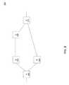
- FIG. 2illustrates a network 200 having network devices (e.g. routers, bridges, switches, hubs) A 202 , B 204 , C 206 , D 208 , and E 210 .
- Routers A 202 and E 210have MEPs at the same level belonging to the same MA.
- the MEP in A 202may communicate with the MEP in E 210 by transmitting OAM packets out of A 202 through the interface coupled to D 208 , and then packet is forwarded by D 208 to destination MEP at E 210 .
- Messagessuch as keep alive messages (also referred to as Continuity Check Messages or CCM), may be sent from the customer level MEP at A 202 to destination MEP at E 210 .
- OAM messagessuch as CCM may be locally generated by an OAM client.
- the data traffic other than OAM traffic between A and Emay continue by transiting through a new route such as through B 204 and C 206 .
- the data traffic other than OAM trafficwhich can be referred to as “routed traffic” relatively quickly adapts to a new route to E 210 because a routing protocol (e.g. Border Gateway Protocol (BGP), Open Shortest Path First (OSPF)) would update the routing table (also referred to herein as “forwarding table”) at A 202 , where the routed packets rely upon the routing table in order to determine the interface through which to exit the router (i.e. “egress interface”).
- Border Gateway ProtocolBGP
- OSPFOpen Shortest Path First
- OAM packets which are locally generated, however,are injected into an egress packet processing pipeline below the network layer and rely upon an MEP database to determine the egress interface.
- the MEP databaseis a database dedicated for OAM use.
- the MEP databaseis updated based upon received CCM that are received on an interface.
- the OAM packetsmay continue to use the failed route to the destination MEP (e.g. E 210 ) and incorrectly report failure of the destination MEP as well as fail to protect the actual path (in this case, the new path through B 204 and C 206 to E 210 ) through which the routed traffic reached E 210 .
- Embodimentsare directed to improving conventional OAM operations by ensuring OAM packets, such as, for example, Ethernet OAM packets exchanged between MEP down entities (e.g. MEPs protecting a network between two network devices) in a MA, are forwarded using the latest reachability information.
- OAM packetssuch as, for example, Ethernet OAM packets exchanged between MEP down entities (e.g. MEPs protecting a network between two network devices) in a MA
- MEP down entitiese.g. MEPs protecting a network between two network devices
- Embodimentsimprove upon the conventional OAM operations by, for example, more quickly and flexibly protecting the traffic paths when a change in a path between MEP down entities occur. Further, false alarms, caused by incorrect detection of a network device failure, are reduced during network reachability changes.
- Methods, systems, and computer readable media for transmitting an OAM packet from a source network device to a destination network deviceinclude generating an OAM protocol data unit (PDU) at the source network device, injecting the OAM PDU in an ingress packet processing pipeline, determining an egress interface of the source network device through which to transmit the OAM PDU to the destination network device, encapsulating the OAM PDU in one or more protocol headers in an egress packet processing pipeline, and transmitting the encapsulated OAM PDU from the egress interface as the OAM packet.
- the injected OAM PDUis associated with an indication to bypass at least a portion of ingress packet processing.
- FIG. 1illustrates an exemplary network diagram showing OAM entities in network devices.
- FIG. 2illustrates a network diagram illustrating two alternate paths between OAM entities.
- FIG. 3illustrates OAM entities, MEP up and MEP down in network devices.
- FIG. 4Aillustrates a layered network packet processing logic stack, in accordance with an embodiment.
- FIG. 4Billustrates a OAM protocol data unit format, in accordance with an embodiment.
- FIG. 4Cillustrates a OAM protocol data unit format in accordance with an embodiment.
- FIG. 5illustrates a network device, in accordance with an embodiment.
- FIG. 6illustrates a flowchart of a method to transmit an OAM packet in accordance with an embodiment.
- Embodimentsprovide for transmitting OAM packets in a manner that is highly responsive to the dynamic topology and reachability changes between two management entities in a network. For example, CCM is injected below the network layer at MEP down entities, so as to be transmitted over the same network paths that are taken by routed traffic.
- FIG. 3illustrates OAM entities, “MEP up” and “MEP down” in network devices.
- Each MEP up entitymonitors the path between itself and another MEP, and the monitored path (e.g. 324 in FIG. 3 , below) includes the packet forwarding and relay functions in the two entities.
- Each MEP down entityalso monitors the path between itself and another MEP, but the monitored path (e.g. 330 in FIG. 3 , below) extends from the egress interface of one MEP down entity to the egress interface of the other MEP down entity.
- Network device 300may be a router, bridge, switch, hub or other packet/frame forwarding entity at the edge of a network, such as any of devices 102 , 104 , 106 , 108 , 110 and 112 in FIG. 1 .
- Network device 300has at least one interface at the edge of the network in which it is located.
- customer router 102includes an internal interface 122 and an edge interface 124 .
- Edge interface 124couples customer router 102 and its network 101 to operator network 105 .
- MEPsprovides for OAM over a MA in a single MD.
- a service instance or MAcan span more than one interconnected provider bridged network in order to represent a service to a customer.
- a unique virtual LAN identifier (VLAN ID)identifies each MA over the network.
- MEP upis designed to manage the connection between two MEP entities, where the connection includes the path within each of the network devices hosting the respective MEPs.
- an MEP up managed connection 324includes the path between an MEP up 320 in an ingress interface 306 of network device 302 and an MEP up 322 in an ingress interface 312 of network device 304 .
- the MEP up path 324includes ingress interfaces 320 and 322 , the switching fabrics 310 and 316 , egress interfaces 308 and 314 , and the intervening network path between network devices 302 and 304 .
- Thisalso includes the protocol processing, including network layer protocol processing, that is performed in forwarding routed packets through by a network device.
- the MEP down managed connection 330extends between an MEP down entity 326 in egress interface 308 of network device 302 and MEP down entity 328 in egress interface 314 of network device 304 .
- the MEP down association 330concerns the network between the edges of two selected network devices, and in particular, does not concern the switching fabrics of the respective network devices.
- the MEP down associationas described below, does not concern network layer packet processing at the respective network devices having the MEPs.
- FIG. 4Aillustrates a layered network packet processing logic stack including facilities for processing Ethernet OAM protocol packets.
- Network packet processing logic stack 400represents the general sequence of operations applied to packet processing in an Ethernet OAM-enabled network device.
- Protocol stack 400illustrates the lower protocol layers (e.g. network layer and below) represented in network protocol models such as the OSI network protocol stack, with the addition of a special sub-layer (also referred to as a “shim layer”) for Ethernet OAM functions.
- a special sub-layeralso referred to as a “shim layer”
- a network devicesuch as network device 106 may include protocol stack 400 .
- a packet 422 from a networke.g. networks 102 or 105 coupled to network device 106 ) that enters (i.e. an ingress packet) network device 106 through an ingress interface would traverse, in order, a physical layer (layer 1) 402 protocol processing, data link layer (layer 2) 404 processing, and OAM layer 408 (also referred to as a “shim layer”) processing.
- OAM packetsmay be processed entirely at the OAM layer 408 and layers below.
- Other ingress packetse.g. non-OAM packets
- non-OAM packetsmay entirely bypass the OAM layer.
- Packets that are to exitare processed from higher to lower protocol layers. For example, packet 424 which may have been generated by an application on network device 106 or which may be handled by network device 106 to be forwarded, may begin processing at network layer 410 or above. Accordingly, many non-OAM packets may enter protocol processing at network layer 410 or higher layers 412 . These egress packets, after being processed by network layer 410 , proceed through link layer 404 , and physical 402 layers before exiting the network device. OAM packets being transmitted from the network device enter protocol processing at OAM layer 408 , and are processed through link 404 , and physical 402 layers before exiting the device. Non-OAM packets may completely bypass OAM layer processing.
- An OAM client 416interacts with the OAM layer 408 to facilitate OAM processing.
- OAM packetis received by an OAM-enabled link layer, the packet is passed to the OAM client for processing.
- the packetmay be discarded if received by a link layer that does not support OAM.
- OAM client 416may operate to provide fault management functions defined for an MEP in an Ethernet OAM-enabled network.
- MEPsperiodically exchange CCM to detect loss of continuity or incorrect network connections.
- a CCMis multicast to each MEP in a MA at each administrative level.
- MEPssend loopback messages (LBM) to verify connectivity with another MEP or MIP for a specific MA.
- Loopbackis a ping-like request/reply function.
- a MEPsends a loopback request message to another MEP or MIP, which generates a subsequent Loopback Reply (LRM).
- LBMs/LRMsare used to verify bidirectional connectivity. They are typically initiated by operator command. However, an MEP can be provisioned to send LBMs periodically.
- LTMLink Trace Messages
- MEPsmulticast Link Trace Messages (LTMs) on a particular MA to identify adjacency relationships with remote MEPs and MIPs at the same administrative level.
- LTMcan also be used for fault isolation.
- the message body of an LTMincludes a destination MAC address of a target MEP that terminates the link trace.
- LTRLink Trace Reply
- An LTMeffectively traces the path to the target MEP.
- an MEPWhen an MEP detects a connectivity failure at level N, for example, due to an absence of CCM from an MEP, it will multicast Alarm Indication Signals (AIS) in the direction away from the detected failure at the next most superior level to inform clients that a transport path and/or a service instance has failed.
- AISAlarm Indication Signals
- FIG. 4Billustrates an OAM protocol data unit (PDU) 430 , according to an embodiment.
- the OAM PDUcan contain any of the OAM messages defined according to protocols, for example, such as IEEE 802.1ag.
- CCMis an exemplary OAM message that can be in the form of OAM PDU 430 .
- OAM PDU 430includes destination address 432 , source address 434 , Ethertype 436 , OAM payload 438 and FCS 439 fields.
- the destination address 432 and source address 434may be in the form of data link layer addresses such as Ethernet addresses.
- Ethertypeindicates the type of payload.
- OAM payload 438includes the OAM message content, such as, CCM, LBM, and the like.
- FCS 439is a trailer and can include a frame check sequence.
- a special header(e.g. traffic management header) 431 can be associated with OAM PDU 430 .
- Special header 431may be associated with the PDU as an attached header field as shown, or by being associated via a pointer.
- Special header 431includes an indication to the ingress packet processing pipeline that the associated OAM PDU does not require farther packet processing, and only requires forwarding table lookup for the packet destination.
- Special header 431includes a pointer to an entry in the forwarding table. Specifically, the pointer refers to the entry that corresponds to the destination MEP for the PDU.
- FIG. 4Cillustrates an OAM packet (referred to herein interchangeably as an OAM frame) 440 in the form after Ethernet encapsulation.
- OAM PDU 430is encapsulated by adding a MPLS/IP header 444 to form a MPLS/IP packet including the OAM PDU 430 .
- the MPLS/IP packetis then again encapsulated by adding an Ethernet header 442 , in order to be transmitted to the nexthop over an Ethernet WAN link.
- the term OAM packetis used to refer to a packet of the form shown in 440 , and also an OAM PDU 430 encapsulated by adding MPLS/IP header 444 .
- the MPLS/IP encapsulationis one of many encapsulations that can be used in embodiments.
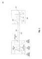
- FIG. 5illustrates a network device 500 , according to an embodiment.
- Network device 500may be a router, bridge, switch, huh or other device which operates to forward data and control packets (or frames).
- Network device 500may, in various embodiments, operate as a packet (or frame) forwarding device located in various network locations, such as, but not limited to, locations corresponding to packet forwarding devices 102 , 104 , 106 , 108 , 110 and 112 , illustrated in FIG. 1 .
- Network device 500includes a plurality of line cards 502 and 504 , a switch fabric 506 , an OAM processing module 508 , an MEP table 510 , a forwarding table 512 , routing protocol processing 560 , higher layer protocol processing 570 , OAM client 580 , and an interconnection infrastructure 514 .
- Interconnection infrastructure 514provides interconnection among components of network device 500 .
- Switch fabric 506operates to transfer a packet between line cards.
- Each line card 502 and 504includes some or all of the logic to perform packet processing on ingress and egress packets.
- ingress packetscan enter network device 500 through ingress interface 532 and are processed in an ingress packet processing logic 542 (also referred to as “ingress packet processing pipeline”).
- Ingress packet processing logic 542includes lower layer protocols 544 (e.g. physical and data link layers), an OAM processing shim layer 546 , and higher layer protocols 548 (e.g. network layer and above).
- An egress packetcan enter line card 502 from switch fabric 506 , and is subject to egress packet processing logic 552 (also referred to as “egress packet processing pipeline”). As discussed above, switch fabric 506 operates to transfer a packet between line cards. After completion of egress packet processing, the packet exits network device 500 through egress interface 534 .
- Egress packet processing logic 552can include higher layer protocols 558 (network and higher layers). OAM shim layer 556 , and lower layer protocols 554 (e.g. data link and physical layers).
- the ingress packet processing 542 and egress packet processing 552may employ a protocol stack such as protocol stack 400 described above.
- ingress packet processing 542 and egress packet processing 552implement the layers 1-3 shown in protocol stack 400 , and the OAM shim layer.
- Line card 502may also implement the OAM client 580 , such as OAM client 416 , in order to provide Ethernet OAM functionality to network device 500 .
- Network device 500may include a bypass packet processing block 522 .
- a packet in the ingress packet processing pipeline 542can be processed in bypass packet processing block 522 .
- Bypass packet processing block 522may either completely bypass any ingress packet processing.
- bypass packet processing blockmay access the forwarding table based upon the pointer to an entry of the forwarding table that is included in the special header of the packet. The packet then enters into egress packet processing.
- an ingress packet from the OAM shim layer 546 or early in the processing of the network layer 548may enter bypass processing 522 .
- the packetafter accessing the forwarding table using the pointer included in the special header, the packet is entered into the egress processing pipeline 552 at the OAM shim layer 556 or later stages of egress network layer processing 558 . Therefore, one or more layers of ingress and/or egress are bypassed for packets with the mentioned indication.
- Network device 500includes a forwarding table 512 .
- Forwarding table 512can include forwarding entries to destination nodes and networks reachable from network device 500 . Each entry may include a destination, a nexthop, an egress interface, and protocol or encapsulation information for that egress interface. Forwarding table 512 is updated based upon routing protocols 560 implemented in network device 500 . For example, when a topology change occurs in the network, an entry associated with a particular destination may be updated with a new nexthop and egress interface as determined by routing protocols 560 .
- a packetis processed based upon one or more of a source and a destination address, such as for example, a source Internet Protocol (IP) address and a destination IP address.
- a source and a destination addresssuch as for example, a source Internet Protocol (IP) address and a destination IP address.
- forwarding table 512includes information needed to identify a nexthop (e.g., a network device that is next in the path to the destination as indicated by the destination IP address) and the interface of network device 500 through which the packet is to be transmitted.
- One or more routing protocols 560such as, but not limited to, BGP, OSPF or Routing Information Protocol (RIP), are used to maintain forwarding table 512 .
- forwarding table 512is updated by dynamic routing protocols, any changes to reachability of networks and/or other network devices from network device 500 are relatively quickly reflected in the forwarding table 512 . As a result, routed packets that either originates from, or are forwarded by, network device 500 can quickly start using an alternative egress interface and/or nexthop to reach the respective destinations.
- Higher layer protocols 570such as, but not limited to, transport protocols and/or application layer protocols can be implemented in network device 500 .
- Higher layer protocolscan provide transport layer (e.g. Transmission Control Protocol (TCP), User Datagram Protocol (UDP)) and other services at layers higher than the network layer.
- Transport layere.g. Transmission Control Protocol (TCP), User Datagram Protocol (UDP)
- UDPUser Datagram Protocol
- Network management protocolssuch as, Simple Network Management Protocol (SNMP).
- SNMPSimple Network Management Protocol
- OAM client 580in association with ingress and egress packet processing logic, 542 and 552 respectively, and shim OAM layers 546 and 556 between link layer and network layer in the protocol processing logic, operates to provide Ethernet OAM functionality to network device 500 .
- an OAM clientsuch as OAM client 580 communicates with other Ethernet OAM entities in network devices to maintain associations known as MA.
- One of the functions, or protocols, performed by the OAM clientis to periodically issue CCM messages (also referred to as “heartbeat messages”).
- network device 500When network device 500 includes OAM MEP functions, then network device 500 includes an MEP table 510 .
- MEP table 510includes information that may be configured or learned.
- MEP table 510includes an entry for each of the other MEPs in a corresponding MA.
- OAM processing 508 and OAM client 580operate to update the MEP table 510 based upon CCM received from other entities in the MA. For example, when a CCM is received from a peer MEP down entity, the egress interface and next hop to reach that peer MEP may be updated in an entry in the MEP table 510 .
- OAM client 580maintains one or more pointers to entries in the forwarding table 512 that correspond to MEPs listed in MEP table 510 .
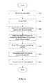
- FIG. 6illustrates a flowchart of a method 600 to transmit a packet from a network device, in accordance with an embodiment.
- Method 600operates to transmit packets generated at a network device at a protocol layer below the network layer in a manner that takes advantage of routing protocols that operate at the network layer.
- the packet transmittedis an Ethernet OAM packet.
- the packetis an Ethernet OAM containing a CCM (“CCM packet”).
- the CCM packetis generated (e.g. originated) by the transmitting network device (e.g. network device 500 ).
- CCM packetsare multicast to all MIPs and MEPs associated with a given MA. Use of a multicast address allows for discovery of remote MEP MAC addresses and the detection of network misconnections. A unicast MAC address may be used if the detection of misconnections is not required.
- a network device operating as an MEPtransmits CCM packets on its associated Ethernet connections at a configured transmission rate.
- OAM packets to other MEPsare transmitted through the egress interface indicated in the MEP database.
- the MEP databaseis updated based upon CCM received from peer MEPs, the MEP database may not be updated sufficiently quickly to reflect changes in network reachability to one or more peer MEPs. Therefore, relying upon the MEP database to select the egress interface for CCM packets can result in the network device transmitting CCM packets on already failed paths. Moreover, it may result in false alarms being generated signaling the failure of peer MEPs, based on faulty message paths that are being used.
- Method 600in contrast to the conventional techniques of transmitting locally-generated Ethernet OAM messages, is directed to select the egress interface using the forwarding table, thereby taking advantage of routing protocols that are more responsive to network reachability changes in order to select the best egress interface to reach each peer MEP for locally-generated packets injected below the network layer.
- the destination to which to send the CCM packetis determined.
- Each network device that is configured as an MEPperiodically transmits a CCM to every MEP known to it.
- the respective MEPs to which the network device transmits CCMmay be determined based upon the MEP database.
- the MEP databaseincludes an entry for each MEP that is currently known to the network device.
- the MEP databaseis updated in accordance with CCMs received by the network device.
- CCMsreceived by the network device.
- itcatalogues them in the MEP database indexed by a unique ID of the MEP, e.g. MEP ID.
- MEP IDe.g. MEP ID.
- network device 500receives a CCM message from another MEP A at particular OAM domain level
- the OAM client on the network devicefirst determines if MEP A is already in the MEP database. If MEP is already in the database, then the entry may be updated to indicate the latest time of the last CCM at which it was confirmed that MEP A is alive and reachable.
- a protocol data unitis generated for OAM message.
- the OAM PDUis a CCM PDU.
- Transmitted Ethernet OAM messages or OAM PDUsare of standard length, untagged Ethernet frames within the normal frame length limits in the range 64-1518 bytes.
- the PDUmay include the destination MAC address, the source MAC address, an ethertype value, an OAM message portion, and a frame check sequence.
- the ethertype valueis used to identify the message as an OAM message.
- the OAM message portionincludes the CCM information.
- CCM messagesare one of several messages transmitted by a MEP entity in a network device, in accordance with embodiments.
- Other OAM messagesinclude Loopback Message/Loopback Reply, Linktrace Message/Linktrace Reply, Alarm Indication Signal (AIS), and other messages that can be used for detecting conditions of the network connection between network devices.
- AISAlarm Indication Signal
- the locally-generated PDUis injected into an ingress processing pipeline in the network device.
- the PDUis injected into the ingress processing pipeline in order that it would be transmitted to the determined destination address.
- the PDU that is injectedis an OAM CCM PDU.
- Other locally-generated OAM messages as well as non-OAM messagescan be injected to the ingress processing pipeline in order to be transmitted to a determined destination, and are contemplated as embodiments.
- the injection of the PDU to the ingress processing pipelinemay be performed by an OAM client.
- the injectionmay be to the OAM shim layer that is in between the network layer and link layer of a protocol processing stack.
- OAM client 416may inject a CCM PDU to OAM shim layer 408 .
- Injecting the PDU at the OAM shim layermay be accomplished in any of several techniques.
- a PDUWhen a PDU is injected at the shim layer in the ingress processing pipeline, it is intended that the packet would not be subjected to ingress processing at lower protocol layers than the layer at which it was injected (e.g. OAM shim layer below network layer).
- OAM shim layerbelow network layer.
- by injecting the CCM packet at the shim layerit avoids processing at layers 1-2 (e.g. 402 and 404 , respectively, in FIG. 4 a ) to which any ingress packets that enter the network device from the network through the ingress interface would be subject to.
- the OAM clientmay use an application programming interface (API) of the OAM shim layer to inject the packet.
- APIapplication programming interface
- the generation of the PDU and injection of the PDU to the ingress processing pipelinemay be hardcoded in the OAM shim layer.
- the PDUis injected to the ingress processing pipeline along with a “special header” such as special header 431 illustrated in FIG. 4B .
- the special headerincludes a pointer to an entry in the forwarding table that corresponds to the destination of the PDU.
- the pointer to the corresponding entry in the forwarding tableis determined by the OAM client, which may maintain a list of such corresponding pointers for one or more known MEPs.
- the special headeroperates as an indication to the ingress packet processing pipeline that the injected PDU is to be treated differently than other ingress packets. For example, in subsequent processing of the injected packet through the ingress processing pipeline, no packet processing (e.g. reassembly, other protocol processing etc.) other than forwarding table lookup using the pointer in the special header is required.
- the injected PDUis already in an Ethernet packet format and does not have additional protocol headers encapsulating the PDU. Therefore, conventional ingress packet processing directed at recovering the PDU and placing it in an Ethernet format is unnecessary, and therefore can be bypassed.
- IPInternet Protocol
- MPLSMulti-Protocol Label Switching
- VPLSVirtual Private LAN Service
- the special header injected with the CCM PDUis recognized by protocol logic in the network device as an indication to bypass packet processing in the ingress pipeline except for the forwarding table lookup based upon the pointer to an entry in the forwarding table included in the special header of the PDU.
- a traffic management headersuch as that used in MPLS may be used for the special header.
- the CCM PDUis injected into the ingress processing pipeline at the interface (of the local network device) that is currently shown in the MEP database as being associated with the destination MEP. What is currently shown in the MEP database may be read at the time of selecting an MEP to which the OAM PDU is to be sent.
- the egress interfaceis identified based on the forwarding table entry referenced by the pointer in the special header of the PDU.
- the forwarding tableis accessed based upon the pointer in the special header.
- the destination addresscorresponds to an address of the peer MEP.
- the address or other identity of the destination MEPmay be known from the local MEP database.
- the forwarding table lookupyields the egress interface through which to transmit the packet to the destination MEP.
- the forwarding table lookupcan also yield the nexthop along the path from the egress interface to the destination MEP, and any encapsulation that is required. For example, in addition to indicating the particular egress interface of the network device that is to be used, the corresponding entry in the forwarding table may also indicate the encapsulation that is to be used on the selected egress interface.
- the OAM PDUenters egress packet processing pipeline.
- the OAM PDUenters the egress packet processing pipeline at the egress OAM shim layer or at the network layer layers 408 or 410 illustrated in FIG. 4 ).
- the OAM PDUenters the egress processing pipeline with information indicating the selected egress interface.
- the information indicating the selected egress interfaceincludes the pointer to the corresponding entry or data structure in the forwarding table that was in the special header of the PDU when the PDU was injected to the ingress pipeline.
- the egress processing pipelineencapsulates the OAM PDU by adding one or more headers.
- the forwarding tableindicates the type of encapsulation required for packets exiting the selected egress interface.
- the encapsulationmay be IP.
- the encapsulationmay include one or more of MPLS, VPLS, and the like.
- the encapsulated OAM CCM PDUis transmitted out of the egress interface.
- the encapsulated OAM CCM PDUis transmitted as an Ethernet packet.
- method 600provides for a locally-generated packet by a protocol entity at a protocol layer that occurs before the network layer, where the generated packet is injected into the ingress processing pipeline in order to be transmitted using the forwarding table of the network device.
- the egress interfaceis selected using the forwarding table, thereby enabling that the selection is responsive to any topology and/or reachability changes in the network.
- a locally-generated OAM PDUCCM, for example
- the network deviceimproves the chances that the CCM can reach the destination peer MEP over a valid path. This improves the reliability of CCM as a mechanism to monitor the status of non-adjacent OAM entities, reducing false alarms and providing that the actual path through which packets travel is being protected via the CCM mechanism.
- process 600can be implemented using computer processors, computer logic, ASIC, FPGA, DSP, etc., as will be understood by those skilled in the arts based on the discussion given herein. Accordingly, any processor that performs the processing functions described herein is within the scope and spirit of the present disclosure. Moreover, instructions for process 600 can be encoded in any of a hardware description language, computer programming language, and can be stored in a disk, flash memory, or any other type of tangible computer readable medium.
Landscapes
- Engineering & Computer Science (AREA)
- Computer Networks & Wireless Communication (AREA)
- Signal Processing (AREA)
- Environmental & Geological Engineering (AREA)
- Health & Medical Sciences (AREA)
- Cardiology (AREA)
- General Health & Medical Sciences (AREA)
- Data Exchanges In Wide-Area Networks (AREA)
Abstract
Description
Claims (20)
Priority Applications (1)
| Application Number | Priority Date | Filing Date | Title |
|---|---|---|---|
| US13/631,145US8982710B2 (en) | 2012-09-28 | 2012-09-28 | Ethernet operation and maintenance (OAM) with flexible forwarding |
Applications Claiming Priority (1)
| Application Number | Priority Date | Filing Date | Title |
|---|---|---|---|
| US13/631,145US8982710B2 (en) | 2012-09-28 | 2012-09-28 | Ethernet operation and maintenance (OAM) with flexible forwarding |
Publications (2)
| Publication Number | Publication Date |
|---|---|
| US20140092751A1 US20140092751A1 (en) | 2014-04-03 |
| US8982710B2true US8982710B2 (en) | 2015-03-17 |
Family
ID=50385078
Family Applications (1)
| Application Number | Title | Priority Date | Filing Date |
|---|---|---|---|
| US13/631,145Active2033-02-17US8982710B2 (en) | 2012-09-28 | 2012-09-28 | Ethernet operation and maintenance (OAM) with flexible forwarding |
Country Status (1)
| Country | Link |
|---|---|
| US (1) | US8982710B2 (en) |
Cited By (19)
| Publication number | Priority date | Publication date | Assignee | Title |
|---|---|---|---|---|
| US20140280717A1 (en)* | 2013-03-13 | 2014-09-18 | Cisco Technology, Inc. | Framework for Dynamically Programmed Network Packet Processing |
| US10044606B2 (en) | 2015-06-01 | 2018-08-07 | Ciena Corporation | Continuity check systems and methods using hardware native down maintenance end points to emulate hardware up maintenance end points |
| US20180375748A1 (en)* | 2015-09-29 | 2018-12-27 | Amazon Technologies, Inc. | Network traffic tracking using encapsulation protocol |
| US10212076B1 (en) | 2012-12-27 | 2019-02-19 | Sitting Man, Llc | Routing methods, systems, and computer program products for mapping a node-scope specific identifier |
| US10367737B1 (en) | 2012-12-27 | 2019-07-30 | Sitting Man, Llc | Routing methods, systems, and computer program products |
| US10374938B1 (en) | 2012-12-27 | 2019-08-06 | Sitting Man, Llc | Routing methods, systems, and computer program products |
| US10397101B1 (en) | 2012-12-27 | 2019-08-27 | Sitting Man, Llc | Routing methods, systems, and computer program products for mapping identifiers |
| US10397100B1 (en) | 2012-12-27 | 2019-08-27 | Sitting Man, Llc | Routing methods, systems, and computer program products using a region scoped outside-scope identifier |
| US10404582B1 (en) | 2012-12-27 | 2019-09-03 | Sitting Man, Llc | Routing methods, systems, and computer program products using an outside-scope indentifier |
| US10404583B1 (en) | 2012-12-27 | 2019-09-03 | Sitting Man, Llc | Routing methods, systems, and computer program products using multiple outside-scope identifiers |
| US10411997B1 (en) | 2012-12-27 | 2019-09-10 | Sitting Man, Llc | Routing methods, systems, and computer program products for using a region scoped node identifier |
| US10411998B1 (en) | 2012-12-27 | 2019-09-10 | Sitting Man, Llc | Node scope-specific outside-scope identifier-equipped routing methods, systems, and computer program products |
| US10419334B1 (en) | 2012-12-27 | 2019-09-17 | Sitting Man, Llc | Internet protocol routing methods, systems, and computer program products |
| US10419335B1 (en) | 2012-12-27 | 2019-09-17 | Sitting Man, Llc | Region scope-specific outside-scope indentifier-equipped routing methods, systems, and computer program products |
| US10447575B1 (en) | 2012-12-27 | 2019-10-15 | Sitting Man, Llc | Routing methods, systems, and computer program products |
| US10476787B1 (en) | 2012-12-27 | 2019-11-12 | Sitting Man, Llc | Routing methods, systems, and computer program products |
| US10567179B1 (en)* | 2018-08-31 | 2020-02-18 | Nxp B.V. | Network device and method for performing network operations in a communications network |
| US20200076630A1 (en)* | 2018-08-31 | 2020-03-05 | Nxp B.V. | Network device and method for performing network operations in a communications network |
| US10587505B1 (en) | 2012-12-27 | 2020-03-10 | Sitting Man, Llc | Routing methods, systems, and computer program products |
Families Citing this family (19)
| Publication number | Priority date | Publication date | Assignee | Title |
|---|---|---|---|---|
| US8982710B2 (en)* | 2012-09-28 | 2015-03-17 | Broadcom Corporation | Ethernet operation and maintenance (OAM) with flexible forwarding |
| US9276833B2 (en)* | 2013-07-24 | 2016-03-01 | Cisco Technology, Inc. | Path-ping and ECMP-traceroute for IPv6 overlay virtualized networks |
| EP3152871B1 (en)* | 2014-07-08 | 2018-09-19 | Huawei Technologies Co., Ltd. | Generic operations, administration, and management (oam) function |
| US9923756B2 (en)* | 2014-09-11 | 2018-03-20 | Adva Optical Networking Se | Maintenance entity group end point of a subnetwork within a multi-domain network |
| CN105515807B (en)* | 2014-09-25 | 2020-09-08 | 中兴通讯股份有限公司 | Up cfm message processing method, system and network data exchange device |
| US9838290B2 (en) | 2015-06-30 | 2017-12-05 | Ciena Corporation | Flexible ethernet operations, administration, and maintenance systems and methods |
| US9913116B2 (en)* | 2016-02-24 | 2018-03-06 | Robert D. Pedersen | Multicast expert system information dissemination system and method |
| EP3729735B1 (en) | 2017-12-22 | 2022-07-06 | Telefonaktiebolaget Lm Ericsson (Publ) | Methods and apparatus for configuring a flex ethernet node |
| US10516551B2 (en)* | 2018-01-15 | 2019-12-24 | Futurewei Technologies, Inc. | In-band telemetry with limited extra bytes |
| US10887230B2 (en)* | 2018-02-27 | 2021-01-05 | Cisco Technology, Inc. | In-situ operations, administration, and management (IOAM) and network event correlation for internet of things (IOT) |
| US10785139B1 (en)* | 2018-06-27 | 2020-09-22 | Amazon Technologies, Inc. | Network devices using probes to test forwarding rules |
| US10700957B1 (en) | 2018-06-27 | 2020-06-30 | Amazon Technologies, Inc. | Network devices using probes to test forwarding rules |
| US11563668B1 (en) | 2018-06-27 | 2023-01-24 | Amazon Technologies, Inc. | Network devices using probes to test forwarding rules |
| US10812364B1 (en) | 2018-06-27 | 2020-10-20 | Amazon Technologies, Inc. | Testing forwarding states of a network device using probe detection and reflection |
| US10805199B1 (en) | 2018-06-27 | 2020-10-13 | Amazon Technologies, Inc. | Testing forwarding information in a network switch |
| US10868748B1 (en) | 2018-09-27 | 2020-12-15 | Amazon Technologies, Inc. | Testing forwarding states on multiple pipelines of a network device |
| CN113824608A (en)* | 2020-06-18 | 2021-12-21 | 华为技术有限公司 | BIER OAM detection method, equipment and system |
| CN115914173A (en)* | 2022-11-30 | 2023-04-04 | 苏州盛科通信股份有限公司 | Chip implementation method and application of OAM (operation administration and maintenance) under multi-core architecture |
| US20250097148A1 (en)* | 2023-09-19 | 2025-03-20 | Cisco Technology, Inc. | Service routing using ip encapsulation |
Citations (24)
| Publication number | Priority date | Publication date | Assignee | Title |
|---|---|---|---|---|
| US5903559A (en)* | 1996-12-20 | 1999-05-11 | Nec Usa, Inc. | Method for internet protocol switching over fast ATM cell transport |
| US6069895A (en)* | 1997-08-29 | 2000-05-30 | Nortel Networks Corporation | Distributed route server |
| US20010009549A1 (en)* | 2000-01-24 | 2001-07-26 | International Business Machines Corporation | Method of injecting/extracting control cells in an asynchronous transfer mode (ATM) network |
| US6850520B1 (en)* | 1998-11-04 | 2005-02-01 | Fujitsu Limited | ATM layer cell processing apparatus |
| US20070097857A1 (en)* | 2005-04-15 | 2007-05-03 | Huawei Technologies Co., Ltd. | Method and Apparatus for Fault Management in Ethernet and Multi-Protocol Label Switching Network Interworking Network |
| US20070133564A1 (en)* | 2005-12-09 | 2007-06-14 | Chun Kyung G | Method for propagating maintenance signal in VPWS network using SDH/SONET |
| US20080144657A1 (en)* | 2005-09-15 | 2008-06-19 | Huawei Technologies Co., Ltd. | Method and Apparatus For Realizing the Interworking of Oam Function Between the Ethernet and the Mpls Network |
| US20090238084A1 (en)* | 2008-03-18 | 2009-09-24 | Cisco Technology, Inc. | Network monitoring using a proxy |
| US20100061252A1 (en)* | 2008-09-09 | 2010-03-11 | Sriganesh Kini | Reducing CC Message Transmission in a Provider Network |
| US20100278048A1 (en)* | 2009-05-01 | 2010-11-04 | Hitachi Cable, Ltd. | Network relay device, network, and network maintenance and operation method |
| US20100316103A1 (en)* | 2009-06-15 | 2010-12-16 | Infineon Technologies Ag | Power saving in a communication device |
| US20110080836A1 (en)* | 2009-10-01 | 2011-04-07 | Nortel Networks Limited | Method and Apparatus for Providing Bypass Connectivity Between Routers |
| US20110116385A1 (en)* | 2009-11-13 | 2011-05-19 | Verizon Patent And Licensing Inc. | Network connectivity management |
| US20110116384A1 (en)* | 2009-11-13 | 2011-05-19 | Verizon Patent And Licensing Inc. | Network connectivity management |
| US20110211827A1 (en)* | 2003-03-03 | 2011-09-01 | Soto Alexander I | System and method for performing in-service optical fiber network certification |
| US20120020206A1 (en)* | 2009-04-16 | 2012-01-26 | Italo Busi | Method for Client Data Transmission Through a Packet Switched Provider Network |
| US20120120955A1 (en)* | 2009-09-09 | 2012-05-17 | Maarten Vissers | Method, device and system for interconnecting a multi-protocol label switching network and an ethernet |
| US20120163189A1 (en)* | 2010-12-27 | 2012-06-28 | David Ian Allan | Internetworking Framework for Multi-Protocol Label Switching-Transport Profile and Operation Administration and Maintenance Protocols |
| US20120230207A1 (en)* | 2011-03-07 | 2012-09-13 | Broadcom Corporation | Early detection of loss of continuity in a maintenance association |
| US8385353B2 (en)* | 2009-03-23 | 2013-02-26 | Cisco Technology, Inc. | Connectivity fault management (CFM) auto-provisioning using virtual private LAN service (VPLS) auto-discovery |
| US20130054565A1 (en)* | 2010-05-04 | 2013-02-28 | Mingoa Limited | Identification and verification in communication systems |
| US20140016926A1 (en)* | 2003-03-03 | 2014-01-16 | Alexander Ivan Soto | System and method for performing in-service optical network certification |
| US20140025794A1 (en)* | 2010-07-14 | 2014-01-23 | Domanicom Corporation | Devices, systems, and methods for enabling reconfiguration of services supported by a network of devices |
| US20140092751A1 (en)* | 2012-09-28 | 2014-04-03 | Broadcom Corporation | Ethernet Operation and Maintenance (OAM) with Flexible Forwarding |
- 2012
- 2012-09-28USUS13/631,145patent/US8982710B2/enactiveActive
Patent Citations (24)
| Publication number | Priority date | Publication date | Assignee | Title |
|---|---|---|---|---|
| US5903559A (en)* | 1996-12-20 | 1999-05-11 | Nec Usa, Inc. | Method for internet protocol switching over fast ATM cell transport |
| US6069895A (en)* | 1997-08-29 | 2000-05-30 | Nortel Networks Corporation | Distributed route server |
| US6850520B1 (en)* | 1998-11-04 | 2005-02-01 | Fujitsu Limited | ATM layer cell processing apparatus |
| US20010009549A1 (en)* | 2000-01-24 | 2001-07-26 | International Business Machines Corporation | Method of injecting/extracting control cells in an asynchronous transfer mode (ATM) network |
| US20110211827A1 (en)* | 2003-03-03 | 2011-09-01 | Soto Alexander I | System and method for performing in-service optical fiber network certification |
| US20140016926A1 (en)* | 2003-03-03 | 2014-01-16 | Alexander Ivan Soto | System and method for performing in-service optical network certification |
| US20070097857A1 (en)* | 2005-04-15 | 2007-05-03 | Huawei Technologies Co., Ltd. | Method and Apparatus for Fault Management in Ethernet and Multi-Protocol Label Switching Network Interworking Network |
| US20080144657A1 (en)* | 2005-09-15 | 2008-06-19 | Huawei Technologies Co., Ltd. | Method and Apparatus For Realizing the Interworking of Oam Function Between the Ethernet and the Mpls Network |
| US20070133564A1 (en)* | 2005-12-09 | 2007-06-14 | Chun Kyung G | Method for propagating maintenance signal in VPWS network using SDH/SONET |
| US20090238084A1 (en)* | 2008-03-18 | 2009-09-24 | Cisco Technology, Inc. | Network monitoring using a proxy |
| US20100061252A1 (en)* | 2008-09-09 | 2010-03-11 | Sriganesh Kini | Reducing CC Message Transmission in a Provider Network |
| US8385353B2 (en)* | 2009-03-23 | 2013-02-26 | Cisco Technology, Inc. | Connectivity fault management (CFM) auto-provisioning using virtual private LAN service (VPLS) auto-discovery |
| US20120020206A1 (en)* | 2009-04-16 | 2012-01-26 | Italo Busi | Method for Client Data Transmission Through a Packet Switched Provider Network |
| US20100278048A1 (en)* | 2009-05-01 | 2010-11-04 | Hitachi Cable, Ltd. | Network relay device, network, and network maintenance and operation method |
| US20100316103A1 (en)* | 2009-06-15 | 2010-12-16 | Infineon Technologies Ag | Power saving in a communication device |
| US20120120955A1 (en)* | 2009-09-09 | 2012-05-17 | Maarten Vissers | Method, device and system for interconnecting a multi-protocol label switching network and an ethernet |
| US20110080836A1 (en)* | 2009-10-01 | 2011-04-07 | Nortel Networks Limited | Method and Apparatus for Providing Bypass Connectivity Between Routers |
| US20110116385A1 (en)* | 2009-11-13 | 2011-05-19 | Verizon Patent And Licensing Inc. | Network connectivity management |
| US20110116384A1 (en)* | 2009-11-13 | 2011-05-19 | Verizon Patent And Licensing Inc. | Network connectivity management |
| US20130054565A1 (en)* | 2010-05-04 | 2013-02-28 | Mingoa Limited | Identification and verification in communication systems |
| US20140025794A1 (en)* | 2010-07-14 | 2014-01-23 | Domanicom Corporation | Devices, systems, and methods for enabling reconfiguration of services supported by a network of devices |
| US20120163189A1 (en)* | 2010-12-27 | 2012-06-28 | David Ian Allan | Internetworking Framework for Multi-Protocol Label Switching-Transport Profile and Operation Administration and Maintenance Protocols |
| US20120230207A1 (en)* | 2011-03-07 | 2012-09-13 | Broadcom Corporation | Early detection of loss of continuity in a maintenance association |
| US20140092751A1 (en)* | 2012-09-28 | 2014-04-03 | Broadcom Corporation | Ethernet Operation and Maintenance (OAM) with Flexible Forwarding |
Cited By (49)
| Publication number | Priority date | Publication date | Assignee | Title |
|---|---|---|---|---|
| US10757010B1 (en) | 2012-12-27 | 2020-08-25 | Sitting Man, Llc | Routing methods, systems, and computer program products |
| US10841198B1 (en) | 2012-12-27 | 2020-11-17 | Sitting Man, Llc | Routing methods, systems, and computer program products |
| US12058042B1 (en) | 2012-12-27 | 2024-08-06 | Morris Routing Technologies, Llc | Routing methods, systems, and computer program products |
| US11784914B1 (en) | 2012-12-27 | 2023-10-10 | Morris Routing Technologies, Llc | Routing methods, systems, and computer program products |
| US10212076B1 (en) | 2012-12-27 | 2019-02-19 | Sitting Man, Llc | Routing methods, systems, and computer program products for mapping a node-scope specific identifier |
| US10367737B1 (en) | 2012-12-27 | 2019-07-30 | Sitting Man, Llc | Routing methods, systems, and computer program products |
| US10374938B1 (en) | 2012-12-27 | 2019-08-06 | Sitting Man, Llc | Routing methods, systems, and computer program products |
| US10382327B1 (en) | 2012-12-27 | 2019-08-13 | Sitting Man, Llc | Methods, systems, and computer program products for routing using headers including a sequence of node scope-specific identifiers |
| US10389624B1 (en) | 2012-12-27 | 2019-08-20 | Sitting Man, Llc | Scoped identifier space routing methods, systems, and computer program products |
| US10389625B1 (en) | 2012-12-27 | 2019-08-20 | Sitting Man, Llc | Routing methods, systems, and computer program products for using specific identifiers to transmit data |
| US10397101B1 (en) | 2012-12-27 | 2019-08-27 | Sitting Man, Llc | Routing methods, systems, and computer program products for mapping identifiers |
| US10397100B1 (en) | 2012-12-27 | 2019-08-27 | Sitting Man, Llc | Routing methods, systems, and computer program products using a region scoped outside-scope identifier |
| US10404582B1 (en) | 2012-12-27 | 2019-09-03 | Sitting Man, Llc | Routing methods, systems, and computer program products using an outside-scope indentifier |
| US10404583B1 (en) | 2012-12-27 | 2019-09-03 | Sitting Man, Llc | Routing methods, systems, and computer program products using multiple outside-scope identifiers |
| US10411997B1 (en) | 2012-12-27 | 2019-09-10 | Sitting Man, Llc | Routing methods, systems, and computer program products for using a region scoped node identifier |
| US10411998B1 (en) | 2012-12-27 | 2019-09-10 | Sitting Man, Llc | Node scope-specific outside-scope identifier-equipped routing methods, systems, and computer program products |
| US10419334B1 (en) | 2012-12-27 | 2019-09-17 | Sitting Man, Llc | Internet protocol routing methods, systems, and computer program products |
| US10419335B1 (en) | 2012-12-27 | 2019-09-17 | Sitting Man, Llc | Region scope-specific outside-scope indentifier-equipped routing methods, systems, and computer program products |
| US10447575B1 (en) | 2012-12-27 | 2019-10-15 | Sitting Man, Llc | Routing methods, systems, and computer program products |
| US10476788B1 (en) | 2012-12-27 | 2019-11-12 | Sitting Man, Llc | Outside-scope identifier-equipped routing methods, systems, and computer program products |
| US10476787B1 (en) | 2012-12-27 | 2019-11-12 | Sitting Man, Llc | Routing methods, systems, and computer program products |
| US10498642B1 (en) | 2012-12-27 | 2019-12-03 | Sitting Man, Llc | Routing methods, systems, and computer program products |
| US11196660B1 (en) | 2012-12-27 | 2021-12-07 | Sitting Man, Llc | Routing methods, systems, and computer program products |
| US10574562B1 (en) | 2012-12-27 | 2020-02-25 | Sitting Man, Llc | Routing methods, systems, and computer program products |
| US11012344B1 (en) | 2012-12-27 | 2021-05-18 | Sitting Man, Llc | Routing methods, systems, and computer program products |
| US10587505B1 (en) | 2012-12-27 | 2020-03-10 | Sitting Man, Llc | Routing methods, systems, and computer program products |
| US10862791B1 (en) | 2012-12-27 | 2020-12-08 | Sitting Man, Llc | DNS methods, systems, and computer program products |
| US10805204B1 (en) | 2012-12-27 | 2020-10-13 | Sitting Man, Llc | Routing methods, systems, and computer program products |
| US10594594B1 (en) | 2012-12-27 | 2020-03-17 | Sitting Man, Llc | Routing methods, systems, and computer program products |
| US10785143B1 (en) | 2012-12-27 | 2020-09-22 | Sitting Man, Llc | Routing methods, systems, and computer program products |
| US10652150B1 (en) | 2012-12-27 | 2020-05-12 | Sitting Man, Llc | Routing methods, systems, and computer program products |
| US10652133B1 (en) | 2012-12-27 | 2020-05-12 | Sitting Man, Llc | Routing methods, systems, and computer program products |
| US10652134B1 (en) | 2012-12-27 | 2020-05-12 | Sitting Man, Llc | Routing methods, systems, and computer program products |
| US10708168B1 (en) | 2012-12-27 | 2020-07-07 | Sitting Man, Llc | Routing methods, systems, and computer program products |
| US10721164B1 (en) | 2012-12-27 | 2020-07-21 | Sitting Man, Llc | Routing methods, systems, and computer program products with multiple sequences of identifiers |
| US10735306B1 (en) | 2012-12-27 | 2020-08-04 | Sitting Man, Llc | Routing methods, systems, and computer program products |
| US10764171B1 (en) | 2012-12-27 | 2020-09-01 | Sitting Man, Llc | Routing methods, systems, and computer program products |
| US10757020B2 (en) | 2012-12-27 | 2020-08-25 | Sitting Man, Llc | Routing methods, systems, and computer program products |
| US20140280717A1 (en)* | 2013-03-13 | 2014-09-18 | Cisco Technology, Inc. | Framework for Dynamically Programmed Network Packet Processing |
| US9462043B2 (en)* | 2013-03-13 | 2016-10-04 | Cisco Technology, Inc. | Framework for dynamically programmed network packet processing |
| US10044606B2 (en) | 2015-06-01 | 2018-08-07 | Ciena Corporation | Continuity check systems and methods using hardware native down maintenance end points to emulate hardware up maintenance end points |
| US10917322B2 (en)* | 2015-09-29 | 2021-02-09 | Amazon Technologies, Inc. | Network traffic tracking using encapsulation protocol |
| US20180375748A1 (en)* | 2015-09-29 | 2018-12-27 | Amazon Technologies, Inc. | Network traffic tracking using encapsulation protocol |
| US10615992B2 (en)* | 2018-08-31 | 2020-04-07 | Nxp B.V. | Network device and method for performing network operations in a communications network |
| CN110875866A (en)* | 2018-08-31 | 2020-03-10 | 恩智浦有限公司 | Network device and method for performing network operations in a communication network |
| US20200076630A1 (en)* | 2018-08-31 | 2020-03-05 | Nxp B.V. | Network device and method for performing network operations in a communications network |
| US20200076629A1 (en)* | 2018-08-31 | 2020-03-05 | Nxp B.V. | Network device and method for performing network operations in a communications network |
| US10567179B1 (en)* | 2018-08-31 | 2020-02-18 | Nxp B.V. | Network device and method for performing network operations in a communications network |
| CN110875866B (en)* | 2018-08-31 | 2022-08-19 | 恩智浦有限公司 | Network device and method for performing network operations in a communication network |
Also Published As
| Publication number | Publication date |
|---|---|
| US20140092751A1 (en) | 2014-04-03 |
Similar Documents
| Publication | Publication Date | Title |
|---|---|---|
| US8982710B2 (en) | Ethernet operation and maintenance (OAM) with flexible forwarding | |
| EP3223461B1 (en) | Communicating network path and status information in multi-homed networks | |
| US9019840B2 (en) | CFM for conflicting MAC address notification | |
| US8908537B2 (en) | Redundant network connections | |
| EP2933977B1 (en) | Method, network element and network for integrity check in live connectivity frames | |
| US20160041888A1 (en) | Link state relay for physical layer emulation | |
| US8605603B2 (en) | Route convergence based on ethernet operations, administration, and maintenance protocol | |
| US20180091445A1 (en) | Evpn designated forwarder state propagation to customer edge devices using connectivity fault management | |
| EP3675431B1 (en) | Core isolation for logical tunnels stitching multi-homed evpn and l2 circuit | |
| US20150372901A1 (en) | Pseudowire control channel for signaling events | |
| CN101800662A (en) | Double-returning protection switching method based on VPLS and system | |
| US11601335B2 (en) | Methods and systems for neighbor-acknowledged graceful insertion/removal protocol | |
| CN101826990A (en) | Method, device and system for detecting connectedness of virtual pseudo wires | |
| US8483069B1 (en) | Tracing Ethernet frame delay between network devices | |
| US8670299B1 (en) | Enhanced service status detection and fault isolation within layer two networks | |
| US8724454B2 (en) | System and method for summarizing alarm indications in a network environment | |
| US12095642B2 (en) | Remote reachability checks in a distributed tunnel fabric | |
| US9565054B2 (en) | Fate sharing segment protection | |
| Saini | Implementation of the OAM (Operations, Administration, and Maintenance) over Provider Backbone Bridge (802.1 ah) Network |
Legal Events
| Date | Code | Title | Description |
|---|---|---|---|
| AS | Assignment | Owner name:BROADCOM CORPORATION, CALIFORNIA Free format text:ASSIGNMENT OF ASSIGNORS INTEREST;ASSIGNOR:MEILIK, ISRAEL;REEL/FRAME:029800/0087 Effective date:20130103 | |
| AS | Assignment | Owner name:BROADCOM CORPORATION, CALIFORNIA Free format text:ASSIGNMENT OF ASSIGNORS INTEREST;ASSIGNORS:MEILIK, ISRAEL;STERN, YORAM;SIGNING DATES FROM 20130131 TO 20130203;REEL/FRAME:034784/0204 | |
| STCF | Information on status: patent grant | Free format text:PATENTED CASE | |
| AS | Assignment | Owner name:BANK OF AMERICA, N.A., AS COLLATERAL AGENT, NORTH CAROLINA Free format text:PATENT SECURITY AGREEMENT;ASSIGNOR:BROADCOM CORPORATION;REEL/FRAME:037806/0001 Effective date:20160201 Owner name:BANK OF AMERICA, N.A., AS COLLATERAL AGENT, NORTH Free format text:PATENT SECURITY AGREEMENT;ASSIGNOR:BROADCOM CORPORATION;REEL/FRAME:037806/0001 Effective date:20160201 | |
| AS | Assignment | Owner name:AVAGO TECHNOLOGIES GENERAL IP (SINGAPORE) PTE. LTD., SINGAPORE Free format text:ASSIGNMENT OF ASSIGNORS INTEREST;ASSIGNOR:BROADCOM CORPORATION;REEL/FRAME:041706/0001 Effective date:20170120 Owner name:AVAGO TECHNOLOGIES GENERAL IP (SINGAPORE) PTE. LTD Free format text:ASSIGNMENT OF ASSIGNORS INTEREST;ASSIGNOR:BROADCOM CORPORATION;REEL/FRAME:041706/0001 Effective date:20170120 | |
| AS | Assignment | Owner name:BROADCOM CORPORATION, CALIFORNIA Free format text:TERMINATION AND RELEASE OF SECURITY INTEREST IN PATENTS;ASSIGNOR:BANK OF AMERICA, N.A., AS COLLATERAL AGENT;REEL/FRAME:041712/0001 Effective date:20170119 | |
| MAFP | Maintenance fee payment | Free format text:PAYMENT OF MAINTENANCE FEE, 4TH YEAR, LARGE ENTITY (ORIGINAL EVENT CODE: M1551); ENTITY STATUS OF PATENT OWNER: LARGE ENTITY Year of fee payment:4 | |
| AS | Assignment | Owner name:AVAGO TECHNOLOGIES INTERNATIONAL SALES PTE. LIMITE Free format text:MERGER;ASSIGNOR:AVAGO TECHNOLOGIES GENERAL IP (SINGAPORE) PTE. LTD.;REEL/FRAME:047229/0408 Effective date:20180509 | |
| AS | Assignment | Owner name:AVAGO TECHNOLOGIES INTERNATIONAL SALES PTE. LIMITE Free format text:CORRECTIVE ASSIGNMENT TO CORRECT THE EFFECTIVE DATE PREVIOUSLY RECORDED ON REEL 047229 FRAME 0408. ASSIGNOR(S) HEREBY CONFIRMS THE THE EFFECTIVE DATE IS 09/05/2018;ASSIGNOR:AVAGO TECHNOLOGIES GENERAL IP (SINGAPORE) PTE. LTD.;REEL/FRAME:047349/0001 Effective date:20180905 | |
| AS | Assignment | Owner name:AVAGO TECHNOLOGIES INTERNATIONAL SALES PTE. LIMITE Free format text:CORRECTIVE ASSIGNMENT TO CORRECT THE PATENT NUMBER 9,385,856 TO 9,385,756 PREVIOUSLY RECORDED AT REEL: 47349 FRAME: 001. ASSIGNOR(S) HEREBY CONFIRMS THE MERGER;ASSIGNOR:AVAGO TECHNOLOGIES GENERAL IP (SINGAPORE) PTE. LTD.;REEL/FRAME:051144/0648 Effective date:20180905 | |
| MAFP | Maintenance fee payment | Free format text:PAYMENT OF MAINTENANCE FEE, 8TH YEAR, LARGE ENTITY (ORIGINAL EVENT CODE: M1552); ENTITY STATUS OF PATENT OWNER: LARGE ENTITY Year of fee payment:8 |