US8982360B2 - Apparatus and method of using a light conduit in a position detector - Google Patents
Apparatus and method of using a light conduit in a position detectorDownload PDFInfo
- Publication number
- US8982360B2 US8982360B2US13/778,927US201313778927AUS8982360B2US 8982360 B2US8982360 B2US 8982360B2US 201313778927 AUS201313778927 AUS 201313778927AUS 8982360 B2US8982360 B2US 8982360B2
- Authority
- US
- United States
- Prior art keywords
- source
- detector
- control circuits
- sensor
- radiant energy
- Prior art date
- Legal status (The legal status is an assumption and is not a legal conclusion. Google has not performed a legal analysis and makes no representation as to the accuracy of the status listed.)
- Active, expires
Links
- 238000000034methodMethods0.000titledescription9
- 230000003287optical effectEffects0.000claimsabstractdescription6
- 239000007787solidSubstances0.000claimsabstract2
- 239000000835fiberSubstances0.000claimsdescription12
- 230000008878couplingEffects0.000claims1
- 238000010168coupling processMethods0.000claims1
- 238000005859coupling reactionMethods0.000claims1
- 230000005540biological transmissionEffects0.000description6
- 238000010586diagramMethods0.000description6
- 235000014676Phragmites communisNutrition0.000description2
- 238000004891communicationMethods0.000description2
- 238000012986modificationMethods0.000description2
- 230000004048modificationEffects0.000description2
- 238000012544monitoring processMethods0.000description2
- 238000001208nuclear magnetic resonance pulse sequenceMethods0.000description2
- 239000004020conductorSubstances0.000description1
- 230000003247decreasing effectEffects0.000description1
- 238000001514detection methodMethods0.000description1
- 238000005516engineering processMethods0.000description1
- 230000001747exhibiting effectEffects0.000description1
Images


Classifications
- G—PHYSICS
- G08—SIGNALLING
- G08B—SIGNALLING OR CALLING SYSTEMS; ORDER TELEGRAPHS; ALARM SYSTEMS
- G08B13/00—Burglar, theft or intruder alarms
- G08B13/02—Mechanical actuation
- G08B13/08—Mechanical actuation by opening, e.g. of door, of window, of drawer, of shutter, of curtain, of blind
- G—PHYSICS
- G01—MEASURING; TESTING
- G01J—MEASUREMENT OF INTENSITY, VELOCITY, SPECTRAL CONTENT, POLARISATION, PHASE OR PULSE CHARACTERISTICS OF INFRARED, VISIBLE OR ULTRAVIOLET LIGHT; COLORIMETRY; RADIATION PYROMETRY
- G01J1/00—Photometry, e.g. photographic exposure meter
- G01J1/10—Photometry, e.g. photographic exposure meter by comparison with reference light or electric value provisionally void
- G01J1/16—Photometry, e.g. photographic exposure meter by comparison with reference light or electric value provisionally void using electric radiation detectors
- G01J1/18—Photometry, e.g. photographic exposure meter by comparison with reference light or electric value provisionally void using electric radiation detectors using comparison with a reference electric value
- G—PHYSICS
- G08—SIGNALLING
- G08B—SIGNALLING OR CALLING SYSTEMS; ORDER TELEGRAPHS; ALARM SYSTEMS
- G08B13/00—Burglar, theft or intruder alarms
- G08B13/18—Actuation by interference with heat, light, or radiation of shorter wavelength; Actuation by intruding sources of heat, light, or radiation of shorter wavelength
- G08B13/181—Actuation by interference with heat, light, or radiation of shorter wavelength; Actuation by intruding sources of heat, light, or radiation of shorter wavelength using active radiation detection systems
- G08B13/183—Actuation by interference with heat, light, or radiation of shorter wavelength; Actuation by intruding sources of heat, light, or radiation of shorter wavelength using active radiation detection systems by interruption of a radiation beam or barrier
- G08B13/186—Actuation by interference with heat, light, or radiation of shorter wavelength; Actuation by intruding sources of heat, light, or radiation of shorter wavelength using active radiation detection systems by interruption of a radiation beam or barrier using light guides, e.g. optical fibres
Definitions
- the applicationpertains to position detectors, such as door or window intrusion sensors. More particularly, the application pertains to such detectors which incorporate a fiber optic element, or other type of light pipe, to return light transmitted from a detector mounted on a movable door or window through a portion of an adjacent non-movable frame to the detector for analysis.
- position detectorssuch as door or window intrusion sensors. More particularly, the application pertains to such detectors which incorporate a fiber optic element, or other type of light pipe, to return light transmitted from a detector mounted on a movable door or window through a portion of an adjacent non-movable frame to the detector for analysis.
- Mechanical contactscan be easily defeated from the outside by using an additional magnet to keep the reed switch actuated while the window or door is being opened.
- Known intrusion sensors based on IR transmissionhave constantly transmitted the IR. Such devices may be defeated by shining a light, such as flashlight, at the IR sensor, or using a thin mirror as a reflector to defeat the device.
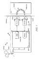
- FIG. 1illustrates a block diagram of a detector in accordance herewith
- FIG. 2is a flow diagram of an exemplary method of operating a detector as in FIG. 1 ;
- FIG. 3illustrates a timing diagram of a transmitted and a received signal of an embodiment hereof
- FIG. 4illustrates a variation of the detector of FIG. 1 ;
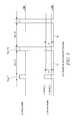
- FIG. 5is a timing diagram of a coded transmitted and received signal.
- embodiments hereofinclude a door, or window detector, mountable on one of a frame, or a door or a window, transmits a coded beam of radiant energy, for example, infrared light toward a second element, such as a door or window or a frame.
- a fiber optic membercan be installed in the second element, such as the adjacent door or window, or frame.
- the beam of radiant energycan be transmitted from a source, via the fiber optic member, back to a sensor.
- the detector and the fiber optic memberare in alignment only when the door, or window, is in a predetermined position relative to the adjacent member, such as the respective frame.
- the detectorwill receive the returned, coded, beam of radiant energy transmitted via the fiber optic member only when the door or window is closed. If the door or window is moved relative to the frame, the transmission through the fiber optic member will be disrupted and the detector will immediately be able to detect the movement and transmit an alarm indictor to an associated security monitoring system.
- the fiber optic membercan have either a constant radius, or be tapered and have a variable, increasing or decreasing, radius from input end to output end.
- a security codecan be used to pulse modulate the transmitted light.
- the transmitted lightcan be modulated by phase shifting, frequency modulation, pulse duration modulation, or the like to increase the security of the transmitted signal. An attacker would have great difficulty, and probably not be able to replicate the transmitted, modulated sequence.
- FIG. 1illustrates a detector 10 which solves the problems mentioned above.
- Embodiments hereofadvantageously use a light transmitting conduit, such as member 12 , to securely transmit a beam of radiant energy, for example infrared light.
- the arrows in conduit 12 in FIG. 1represent the direction of transmission of radiant energy as further discussed below.
- Detector 10includes a housing 16 which can be attached to a door frame, a window frame, a door or a window without limitation.
- Housing 16carries control circuits 18 which could be implemented, at least in part by a programmable processor 18 - 1 and executable instructions, software, 18 - 2 .
- the control circuits 18include an input/output interface 18 - 3 which can be in wired or wireless communication via a medium W displaced monitoring system M.
- a plurality of detectors, 10 - 1 . . . 10 -n, corresponding to detector 10can be in communication with system M.
- control circuits 18can activate drive circuits 20 a , via a modulated signal, for example a pulse sequence, to energize emitter, source 20 b .
- Emitter 20 bin turn outputs a modulated beam of radiant energy, such as infrared, which is coupled to conduit or light pipe 12 when the housing 16 exhibits a predetermined relationship with the conduit or light pipe 12 . For example, when the door is closed against the frame or the window is closed against the frame.
- the light beamtravels through the conduit 12 and is then coupled to detector 22 a , processed by receiving circuits 22 b , and then made available to control circuits 18 . If the transmission path of the beam is disrupted, by opening the door or window; for example, the control circuits can respond to the loss of radiant energy by forwarding an alarm indicator to the system M.
- FIG. 1provides a new and low cost solution to door/window position sensing using a radiant energy conductor 12 , such as a light pipe or fiber optic member for transmission.
- the fiber optic member 12provides a high efficiency transmission medium which promotes detection of received radiant energy.
- the detector 10can be expected to be more reliable and more difficult to be defeated. Since embodiments hereof exhibit both low cost and low power consumption, they can be powered by a batter 26 and are suitable for wireless door/window applications.
- FIG. 2illustrates an exemplary method 200 of operating a detector as in FIG. 1 .
- Process 200is exemplary and is not a limitation hereof. Other processes come within the spirit and scope hereof.
- FIG. 3illustrates a timing diagram of transmitted radiant energy pulses and received radiant energy pulses in accordance with the method of FIG. 2 .
- the detector 10is initialized, as at 210 .
- a pulseis emitted by source 20 b and received at sensor 22 a . If the received optical signal exceeds a predetermined threshold, such as threshold 1 , as at 230 , the next portion of the received pulse sequence is evaluated, as at 240 . If the received value is below a predetermined threshold, such as threshold 2 , as at 250 the process 200 is repeated since the respective door and frame, or window and frame are exhibiting the predetermined, closed state. Otherwise, an alarm can be output, as at 260 .
- FIG. 4illustrates an alternate, variable diameter, tapered fiber optic member 12 - 1 usable with the detector of FIG. 1 .
- FIG. 5illustrates an exemplary timing diagram of coded output control pulses, illustrated at C1, which can be produced by control circuits 18 and which generate coded radiant energy pulses at emitter 20 b .
- the output pulses from emitter 20 bare transmitted, via the fiber optic member 12 to the sensor 22 a .
- Coded, radiant energy signals, illustrated at C2received by sensor 22 a can be converted to electrical waveforms and analyzed in the circuitry 18 of the detector 10 of FIG. 1 .
- control circuits, and instructions 18 - 2can present a time varying modulated sequence of optical signals, to be transmitted by conduit 12 and subsequently received at sensor 22 a and analyzed by the control circuits 18 .
- Such time varying modulated signal packetscan be expected to provide enhanced security for the detector 10 as well as the other members of the plurality 10 -i.
Landscapes
- Physics & Mathematics (AREA)
- General Physics & Mathematics (AREA)
- Spectroscopy & Molecular Physics (AREA)
- Burglar Alarm Systems (AREA)
- Geophysics And Detection Of Objects (AREA)
Abstract
Description
Claims (15)
Priority Applications (5)
| Application Number | Priority Date | Filing Date | Title |
|---|---|---|---|
| US13/778,927US8982360B2 (en) | 2013-02-27 | 2013-02-27 | Apparatus and method of using a light conduit in a position detector |
| EP14154570.7AEP2772889B1 (en) | 2013-02-27 | 2014-02-10 | Apparatus and method of using a light conduit in a position detector |
| ES14154570.7TES2674937T3 (en) | 2013-02-27 | 2014-02-10 | Equipment and method of using a light conduit in a position detector |
| CA2842633ACA2842633A1 (en) | 2013-02-27 | 2014-02-12 | Apparatus and method of using a light conduit in a position detector |
| CN201410066156.XACN104008620B (en) | 2013-02-27 | 2014-02-26 | The apparatus and method of light guide are used in position detector |
Applications Claiming Priority (1)
| Application Number | Priority Date | Filing Date | Title |
|---|---|---|---|
| US13/778,927US8982360B2 (en) | 2013-02-27 | 2013-02-27 | Apparatus and method of using a light conduit in a position detector |
Publications (2)
| Publication Number | Publication Date |
|---|---|
| US20140240717A1 US20140240717A1 (en) | 2014-08-28 |
| US8982360B2true US8982360B2 (en) | 2015-03-17 |
Family
ID=50071489
Family Applications (1)
| Application Number | Title | Priority Date | Filing Date |
|---|---|---|---|
| US13/778,927Active2033-06-02US8982360B2 (en) | 2013-02-27 | 2013-02-27 | Apparatus and method of using a light conduit in a position detector |
Country Status (5)
| Country | Link |
|---|---|
| US (1) | US8982360B2 (en) |
| EP (1) | EP2772889B1 (en) |
| CN (1) | CN104008620B (en) |
| CA (1) | CA2842633A1 (en) |
| ES (1) | ES2674937T3 (en) |
Cited By (8)
| Publication number | Priority date | Publication date | Assignee | Title |
|---|---|---|---|---|
| US20150226637A1 (en)* | 2013-07-31 | 2015-08-13 | Jorge Sanchez | Method and Optical Shield for Detecting Tampering |
| US9990866B2 (en) | 2013-07-31 | 2018-06-05 | Opticallock, Inc. | Container tamper-proof protection by use of printed fiber optics manufacturing and integrated sensors |
| US10107014B2 (en) | 2015-08-30 | 2018-10-23 | Opticallock, Inc. | Security system with anti-tampering sensors and cybersecurity |
| US10341015B1 (en)* | 2015-10-19 | 2019-07-02 | National Technology & Engineering Solutions Of Sandia, Llc | Secure fiber optic seals enabled by quantum optical communication concepts |
| CN111352426A (en)* | 2020-03-17 | 2020-06-30 | 广西柳工机械股份有限公司 | Vehicle obstacle avoidance method, vehicle obstacle avoidance device, vehicle obstacle avoidance system and vehicle |
| US10851562B2 (en)* | 2017-04-28 | 2020-12-01 | The Regents Of The University Of Colorado, A Body Corporate | Passive continuity monitoring device with active features |
| US11881092B1 (en)* | 2023-06-22 | 2024-01-23 | The Adt Security Corporation | Sensor alignment indicator for premises devices of a premises monitoring system |
| US12288452B1 (en)* | 2024-10-17 | 2025-04-29 | Birdie Love Inc. | Portable alarm |
Families Citing this family (2)
| Publication number | Priority date | Publication date | Assignee | Title |
|---|---|---|---|---|
| DE202014104195U1 (en) | 2014-09-05 | 2014-09-17 | Elv Elektronik Ag | sensor device |
| US11293782B2 (en)* | 2016-05-26 | 2022-04-05 | Essence Security International (E.S.I.) Ltd. | Intrusion detecting sensors and method |
Citations (25)
| Publication number | Priority date | Publication date | Assignee | Title |
|---|---|---|---|---|
| US3735353A (en)* | 1971-10-28 | 1973-05-22 | Johnson Service Co | Alarm transmission line security system utilizing pseudo random encoding |
| US3854792A (en)* | 1973-03-22 | 1974-12-17 | Atomic Energy Commission | Fiber optic security seal |
| GB2013332A (en) | 1978-01-28 | 1979-08-08 | Plessey Co Ltd | Improvements in or relating to optical detecting arrangements |
| US4262284A (en)* | 1978-06-26 | 1981-04-14 | Stieff Lorin R | Self-monitoring seal |
| US4447123A (en)* | 1981-07-29 | 1984-05-08 | Ensco Inc. | Fiber optic security system including a fiber optic seal and an electronic verifier |
| US4507654A (en) | 1981-10-30 | 1985-03-26 | A. R. F. Products | Security system with infrared optical position detector |
| US4829174A (en)* | 1986-09-29 | 1989-05-09 | General Motors Corporation | Flexible tube optical intrusion detector |
| US5189396A (en)* | 1990-06-16 | 1993-02-23 | Anatoli Stobbe | Electronic seal |
| US5912619A (en) | 1997-12-31 | 1999-06-15 | Wells Fargo Alarm Systems, Inc. | Security system using optical sensors |
| US5936523A (en)* | 1998-04-24 | 1999-08-10 | West; Joe F. | Device and method for detecting unwanted disposition of the contents of an enclosure |
| US6175675B1 (en)* | 1998-09-14 | 2001-01-16 | Samsung Electronics Co., Ltd. | Apparatus for aligning and method of bonding optical waveguide device to optical fiber block |
| US6420971B1 (en)* | 1999-06-23 | 2002-07-16 | Tripseal Limited | Electronic seal, methods and security system |
| US20030123838A1 (en)* | 2001-10-31 | 2003-07-03 | Chung-Chih Wang | Optical loop-back attenuator |
| US6654523B1 (en)* | 2001-08-10 | 2003-11-25 | Lightwave Microsystems Corporation | Optical alignment guide and method for aligning an optical fiber array with an optical integrated circuit |
| US20040233054A1 (en)* | 2003-03-31 | 2004-11-25 | Neff Raymond Lynn | Wireless monitoring device |
| US20060257092A1 (en)* | 2005-04-19 | 2006-11-16 | Yu Lu | Loop back plug and method |
| US20070146131A1 (en) | 2005-12-23 | 2007-06-28 | Siemens Vdo Automotive | Method for detecting characteristic movements of a vehicle driver for the purpose of diagnosing a lowering of vigilance by said driver |
| US7471203B2 (en)* | 2005-04-26 | 2008-12-30 | Rf Code, Inc. | Tamper monitoring system and method |
| EP2019377A1 (en) | 2007-07-25 | 2009-01-28 | Robert Bosch GmbH | Offset optical security sensor for a door |
| US7714718B2 (en) | 2007-07-25 | 2010-05-11 | Robert Bosch Gmbh | Optical security sensor for a door |
| US7986232B2 (en) | 2006-08-03 | 2011-07-26 | Tyco Safety Products Canada Ltd. | Method and apparatus for using an infrared reflectivity sensor in a security system |
| US8334773B2 (en)* | 2009-08-28 | 2012-12-18 | Deal Magic, Inc. | Asset monitoring and tracking system |
| US8432274B2 (en)* | 2009-07-31 | 2013-04-30 | Deal Magic, Inc. | Contextual based determination of accuracy of position fixes |
| US8456302B2 (en)* | 2009-07-14 | 2013-06-04 | Savi Technology, Inc. | Wireless tracking and monitoring electronic seal |
| US8511911B2 (en)* | 2009-07-28 | 2013-08-20 | Adc Telecommunications, Inc. | Multi-fiber loop back plug |
Family Cites Families (6)
| Publication number | Priority date | Publication date | Assignee | Title |
|---|---|---|---|---|
| CN2446532Y (en)* | 2000-09-07 | 2001-09-05 | 东盈光电科技股份有限公司 | Fiber Path Conditioner |
| AU2002335551A1 (en)* | 2002-08-30 | 2004-04-23 | Kwan-Suk Yang | Fiber optic security system and control method thereof |
| US20070146132A1 (en)* | 2005-12-22 | 2007-06-28 | Florian Krug | Tamper detection system, method and apparatus |
| CN202177957U (en)* | 2011-08-11 | 2012-03-28 | 马强 | Optical fiber conduction foreign matter intrusion monitoring device |
| CN102759211A (en)* | 2012-02-22 | 2012-10-31 | 梁宝利 | Conical light guide pipe energy accumulation emitter |
| CN202584331U (en)* | 2012-05-25 | 2012-12-05 | 南京业祥科技发展有限公司 | Optical fiber on/off active detector |
- 2013
- 2013-02-27USUS13/778,927patent/US8982360B2/enactiveActive
- 2014
- 2014-02-10ESES14154570.7Tpatent/ES2674937T3/enactiveActive
- 2014-02-10EPEP14154570.7Apatent/EP2772889B1/enactiveActive
- 2014-02-12CACA2842633Apatent/CA2842633A1/ennot_activeAbandoned
- 2014-02-26CNCN201410066156.XApatent/CN104008620B/enactiveActive
Patent Citations (27)
| Publication number | Priority date | Publication date | Assignee | Title |
|---|---|---|---|---|
| US3735353A (en)* | 1971-10-28 | 1973-05-22 | Johnson Service Co | Alarm transmission line security system utilizing pseudo random encoding |
| US3854792A (en)* | 1973-03-22 | 1974-12-17 | Atomic Energy Commission | Fiber optic security seal |
| GB2013332A (en) | 1978-01-28 | 1979-08-08 | Plessey Co Ltd | Improvements in or relating to optical detecting arrangements |
| US4262284A (en)* | 1978-06-26 | 1981-04-14 | Stieff Lorin R | Self-monitoring seal |
| US4447123A (en)* | 1981-07-29 | 1984-05-08 | Ensco Inc. | Fiber optic security system including a fiber optic seal and an electronic verifier |
| US4507654A (en) | 1981-10-30 | 1985-03-26 | A. R. F. Products | Security system with infrared optical position detector |
| US4829174A (en)* | 1986-09-29 | 1989-05-09 | General Motors Corporation | Flexible tube optical intrusion detector |
| US5189396A (en)* | 1990-06-16 | 1993-02-23 | Anatoli Stobbe | Electronic seal |
| US5912619A (en) | 1997-12-31 | 1999-06-15 | Wells Fargo Alarm Systems, Inc. | Security system using optical sensors |
| US5936523A (en)* | 1998-04-24 | 1999-08-10 | West; Joe F. | Device and method for detecting unwanted disposition of the contents of an enclosure |
| US6175675B1 (en)* | 1998-09-14 | 2001-01-16 | Samsung Electronics Co., Ltd. | Apparatus for aligning and method of bonding optical waveguide device to optical fiber block |
| US6420971B1 (en)* | 1999-06-23 | 2002-07-16 | Tripseal Limited | Electronic seal, methods and security system |
| US6654523B1 (en)* | 2001-08-10 | 2003-11-25 | Lightwave Microsystems Corporation | Optical alignment guide and method for aligning an optical fiber array with an optical integrated circuit |
| US20030123838A1 (en)* | 2001-10-31 | 2003-07-03 | Chung-Chih Wang | Optical loop-back attenuator |
| US6707979B2 (en)* | 2001-10-31 | 2004-03-16 | Hon Hai Precision Ind. Co., Ltd. | Optical loop-back attenuator |
| US20040233054A1 (en)* | 2003-03-31 | 2004-11-25 | Neff Raymond Lynn | Wireless monitoring device |
| US20060257092A1 (en)* | 2005-04-19 | 2006-11-16 | Yu Lu | Loop back plug and method |
| US7471203B2 (en)* | 2005-04-26 | 2008-12-30 | Rf Code, Inc. | Tamper monitoring system and method |
| US20070146131A1 (en) | 2005-12-23 | 2007-06-28 | Siemens Vdo Automotive | Method for detecting characteristic movements of a vehicle driver for the purpose of diagnosing a lowering of vigilance by said driver |
| US7986232B2 (en) | 2006-08-03 | 2011-07-26 | Tyco Safety Products Canada Ltd. | Method and apparatus for using an infrared reflectivity sensor in a security system |
| US7714718B2 (en) | 2007-07-25 | 2010-05-11 | Robert Bosch Gmbh | Optical security sensor for a door |
| US7834309B2 (en) | 2007-07-25 | 2010-11-16 | Robert Bosch Security Systems, Inc. | Offset optical security sensor for a door |
| EP2019377A1 (en) | 2007-07-25 | 2009-01-28 | Robert Bosch GmbH | Offset optical security sensor for a door |
| US8456302B2 (en)* | 2009-07-14 | 2013-06-04 | Savi Technology, Inc. | Wireless tracking and monitoring electronic seal |
| US8511911B2 (en)* | 2009-07-28 | 2013-08-20 | Adc Telecommunications, Inc. | Multi-fiber loop back plug |
| US8432274B2 (en)* | 2009-07-31 | 2013-04-30 | Deal Magic, Inc. | Contextual based determination of accuracy of position fixes |
| US8334773B2 (en)* | 2009-08-28 | 2012-12-18 | Deal Magic, Inc. | Asset monitoring and tracking system |
Non-Patent Citations (1)
| Title |
|---|
| European Search Report from corresponding EP application 14154570.7, date of search completion Jun. 4, 2014. |
Cited By (13)
| Publication number | Priority date | Publication date | Assignee | Title |
|---|---|---|---|---|
| US9329098B2 (en)* | 2013-07-31 | 2016-05-03 | Opticallock, Inc. | Method and optical shield for detecting tampering |
| US9618421B2 (en) | 2013-07-31 | 2017-04-11 | Opticallock, Inc. | Method and optical shield for detecting tampering |
| US9990866B2 (en) | 2013-07-31 | 2018-06-05 | Opticallock, Inc. | Container tamper-proof protection by use of printed fiber optics manufacturing and integrated sensors |
| US20150226637A1 (en)* | 2013-07-31 | 2015-08-13 | Jorge Sanchez | Method and Optical Shield for Detecting Tampering |
| US10107014B2 (en) | 2015-08-30 | 2018-10-23 | Opticallock, Inc. | Security system with anti-tampering sensors and cybersecurity |
| US10341015B1 (en)* | 2015-10-19 | 2019-07-02 | National Technology & Engineering Solutions Of Sandia, Llc | Secure fiber optic seals enabled by quantum optical communication concepts |
| US10851562B2 (en)* | 2017-04-28 | 2020-12-01 | The Regents Of The University Of Colorado, A Body Corporate | Passive continuity monitoring device with active features |
| CN111352426A (en)* | 2020-03-17 | 2020-06-30 | 广西柳工机械股份有限公司 | Vehicle obstacle avoidance method, vehicle obstacle avoidance device, vehicle obstacle avoidance system and vehicle |
| CN111352426B (en)* | 2020-03-17 | 2021-03-02 | 广西柳工机械股份有限公司 | A vehicle obstacle avoidance method, a vehicle obstacle avoidance device, a vehicle obstacle avoidance system, and a vehicle |
| US11881092B1 (en)* | 2023-06-22 | 2024-01-23 | The Adt Security Corporation | Sensor alignment indicator for premises devices of a premises monitoring system |
| US20240428668A1 (en)* | 2023-06-22 | 2024-12-26 | The Adt Security Corporation | Sensor alignment indicator for premises devices of a premises monitoring system |
| US12380786B2 (en)* | 2023-06-22 | 2025-08-05 | The Adt Security Corporation | Sensor alignment indicator for premises devices of a premises monitoring system |
| US12288452B1 (en)* | 2024-10-17 | 2025-04-29 | Birdie Love Inc. | Portable alarm |
Also Published As
| Publication number | Publication date |
|---|---|
| US20140240717A1 (en) | 2014-08-28 |
| CN104008620B (en) | 2016-12-07 |
| ES2674937T3 (en) | 2018-07-05 |
| EP2772889A1 (en) | 2014-09-03 |
| CN104008620A (en) | 2014-08-27 |
| CA2842633A1 (en) | 2014-08-27 |
| EP2772889B1 (en) | 2018-05-16 |
Similar Documents
| Publication | Publication Date | Title |
|---|---|---|
| US8982360B2 (en) | Apparatus and method of using a light conduit in a position detector | |
| EP3260890B1 (en) | System and method for pulsed based receiver photo sensor | |
| CN104915178B (en) | Optical random number generator and method for generating random numbers | |
| US20160328936A1 (en) | Open Scattered Light Smoke Detector And Testing Device For An Open Scattered Light Smoke Detector Of This Type | |
| US4462022A (en) | Security system with radio frequency coupled remote sensors | |
| US9536413B2 (en) | Verifying and monitoring stove operation | |
| CN108291967A (en) | Use the site safety device of laser radar | |
| WO2011011405A3 (en) | Theft detection systems and methods | |
| RU2015111198A (en) | PRESENCE DETECTOR AND METHOD OF PRESENCE DETECTOR OPERATION | |
| CN102797501B (en) | Wireless portable gas detection alarm control method | |
| EP2942883A1 (en) | Tandem, visible light and rf communication system | |
| JP4430863B2 (en) | Photoelectric proximity switch | |
| US20150372761A1 (en) | Photoelectric sensor with tone modulation | |
| EP3535875A1 (en) | Method and apparatus for free-space optical transmission | |
| CN205426185U (en) | Measure circuit of light curtain | |
| CN106205017A (en) | Open scattered light smoke detector and the mobile communications device for this open scattered light smoke detector | |
| EP2993652B1 (en) | Flame detector using nearband ir temporal signal processing | |
| KR20150132693A (en) | Method And Apparatus for Security Surveillance | |
| JP4467254B2 (en) | Monitoring device | |
| CN202584344U (en) | Smoke sensor of safety protection monitoring system | |
| RU2573261C2 (en) | Infrared active system for monitoring extended security boundaries | |
| KR101469531B1 (en) | Detection Anti-Intruder by using Infrared Sensing Device | |
| RU2720216C2 (en) | Method for remote control of operability of security alarm devices and device for implementation thereof | |
| KR102039569B1 (en) | Method Of Identifying Human Being And Animal Using Microwave Motion Sensor | |
| CN202650173U (en) | Infrared signal detection system |
Legal Events
| Date | Code | Title | Description |
|---|---|---|---|
| AS | Assignment | Owner name:HONEYWELL INTERNATIONAL INC., NEW JERSEY Free format text:ASSIGNMENT OF ASSIGNORS INTEREST;ASSIGNORS:ZHAO, TIANFENG;JIANG, ZHONGYA;POPOWSKI, PAUL M.;AND OTHERS;SIGNING DATES FROM 20130125 TO 20130128;REEL/FRAME:029888/0070 | |
| STCF | Information on status: patent grant | Free format text:PATENTED CASE | |
| MAFP | Maintenance fee payment | Free format text:PAYMENT OF MAINTENANCE FEE, 4TH YEAR, LARGE ENTITY (ORIGINAL EVENT CODE: M1551); ENTITY STATUS OF PATENT OWNER: LARGE ENTITY Year of fee payment:4 | |
| AS | Assignment | Owner name:JPMORGAN CHASE BANK, N.A., AS ADMINISTRATIVE AGENT, NEW YORK Free format text:SECURITY INTEREST;ASSIGNOR:ADEMCO INC.;REEL/FRAME:047337/0577 Effective date:20181025 Owner name:JPMORGAN CHASE BANK, N.A., AS ADMINISTRATIVE AGENT Free format text:SECURITY INTEREST;ASSIGNOR:ADEMCO INC.;REEL/FRAME:047337/0577 Effective date:20181025 | |
| AS | Assignment | Owner name:ADEMCO INC., MINNESOTA Free format text:ASSIGNMENT OF ASSIGNORS INTEREST;ASSIGNOR:HONEYWELL INTERNATIONAL INC.;REEL/FRAME:047909/0425 Effective date:20181029 | |
| AS | Assignment | Owner name:ADEMCO INC., MINNESOTA Free format text:CORRECTIVE ASSIGNMENT TO CORRECT THE PREVIOUS RECORDING BY NULLIFICATION. THE INCORRECTLY RECORDED PATENT NUMBERS 8545483, 8612538 AND 6402691 PREVIOUSLY RECORDED AT REEL: 047909 FRAME: 0425. ASSIGNOR(S) HEREBY CONFIRMS THE ASSIGNMENT;ASSIGNOR:HONEYWELL INTERNATIONAL INC.;REEL/FRAME:050431/0053 Effective date:20190215 | |
| MAFP | Maintenance fee payment | Free format text:PAYMENT OF MAINTENANCE FEE, 8TH YEAR, LARGE ENTITY (ORIGINAL EVENT CODE: M1552); ENTITY STATUS OF PATENT OWNER: LARGE ENTITY Year of fee payment:8 |