US8979744B2 - Tunneling system - Google Patents
Tunneling systemDownload PDFInfo
- Publication number
- US8979744B2 US8979744B2US12/206,391US20639108AUS8979744B2US 8979744 B2US8979744 B2US 8979744B2US 20639108 AUS20639108 AUS 20639108AUS 8979744 B2US8979744 B2US 8979744B2
- Authority
- US
- United States
- Prior art keywords
- catheter
- tunneling
- coupling
- elongate
- longitudinal
- Prior art date
- Legal status (The legal status is an assumption and is not a legal conclusion. Google has not performed a legal analysis and makes no representation as to the accuracy of the status listed.)
- Active, expires
Links
Images


Classifications
- A—HUMAN NECESSITIES
- A61—MEDICAL OR VETERINARY SCIENCE; HYGIENE
- A61M—DEVICES FOR INTRODUCING MEDIA INTO, OR ONTO, THE BODY; DEVICES FOR TRANSDUCING BODY MEDIA OR FOR TAKING MEDIA FROM THE BODY; DEVICES FOR PRODUCING OR ENDING SLEEP OR STUPOR
- A61M25/00—Catheters; Hollow probes
- A61M25/01—Introducing, guiding, advancing, emplacing or holding catheters
- A61M25/0194—Tunnelling catheters
- A—HUMAN NECESSITIES
- A61—MEDICAL OR VETERINARY SCIENCE; HYGIENE
- A61B—DIAGNOSIS; SURGERY; IDENTIFICATION
- A61B17/00—Surgical instruments, devices or methods
- A61B17/32—Surgical cutting instruments
- A—HUMAN NECESSITIES
- A61—MEDICAL OR VETERINARY SCIENCE; HYGIENE
- A61B—DIAGNOSIS; SURGERY; IDENTIFICATION
- A61B17/00—Surgical instruments, devices or methods
- A61B2017/00477—Coupling
- A—HUMAN NECESSITIES
- A61—MEDICAL OR VETERINARY SCIENCE; HYGIENE
- A61B—DIAGNOSIS; SURGERY; IDENTIFICATION
- A61B17/00—Surgical instruments, devices or methods
- A61B17/32—Surgical cutting instruments
- A61B2017/320056—Tunnelers
- A—HUMAN NECESSITIES
- A61—MEDICAL OR VETERINARY SCIENCE; HYGIENE
- A61M—DEVICES FOR INTRODUCING MEDIA INTO, OR ONTO, THE BODY; DEVICES FOR TRANSDUCING BODY MEDIA OR FOR TAKING MEDIA FROM THE BODY; DEVICES FOR PRODUCING OR ENDING SLEEP OR STUPOR
- A61M25/00—Catheters; Hollow probes
- A61M25/01—Introducing, guiding, advancing, emplacing or holding catheters
- A61M25/0102—Insertion or introduction using an inner stiffening member, e.g. stylet or push-rod
Definitions
- the present disclosurerelates generally to a tunneling system, and, more particularly, relates to a tunneling system connectable to a catheter.
- Cathetersare flexible instruments intended for the withdrawal and introduction of fluids relative to body cavities, ducts, and vessels. Catheters have particular application in hemodialysis procedures where blood is withdrawn from a blood vessel for treatment and subsequently returned to the blood vessel for circulation.
- Known hemodialysis cathetersinclude multiple lumens, such as dual lumen or triple-lumen catheters, permitting bi-directional fluid flow within the catheter whereby one lumen is dedicated for withdrawal of blood and the other lumen is dedicated for returning the treated blood to the vessel.
- a multiple lumen catheteris inserted into a body and blood is withdrawn through an arterial lumen of the catheter.
- the removed bloodis directed to a hemodialysis unit which dialyzes, or purifies, the blood to remove waste, and toxins.
- the dialyzed bloodis returned to the subject through a venous lumen of the catheter.
- Various devicesare employed for the insertion of hemodialysis catheters including, e.g., tunnelers, introduction stylets or the like.
- a known technique of inserting a catheterincludes forming a subcutaneous tunnel between two spaced openings in the skin with the use of a trocar or the like. The catheter end is attached to the insertion stylet or trocar and pulled though the tunnel to expose the catheter which is subsequently inserted into, e.g., the jugular vein or other vessel, and routed to the heart. The catheter end must be secured to the trocar in a manner which prevents detachment during passage through the tissue.
- the profile of the insertion devices and cathetermay need to be minimized for ease of passage through the subcutaneous tissue. Adaptability of a broad range of catheters, tunnelers and sheaths is also a consideration.
- the present disclosureis directed to a tunneling system for use with a catheter having at least one longitudinal lumen.
- the tunneling systemincludes an elongate tunneling member defining a longitudinal axis along at least a portion of a longitudinal length thereof.
- the elongate tunneling memberhas a first end and a second end.
- the second end of the elongate tubular memberincludes a coupling segment adapted for securely engaging a catheter.
- the second end of the elongate tubular membermay incorporate different embodiments of couplings segments.
- the coupling segmentmay include at least one pin extending radially with respect to the longitudinal axis. The pin is adapted to be received within at least one hole of the catheter.
- Other embodimentsare also envisioned.
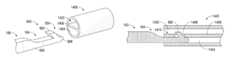
- FIG. 1Ais a perspective view of a tunneling system illustrating an elongate tunneling member and a coupling for releasably connecting a catheter;
- FIG. 1Bis an enlarged perspective view of the tunneling system shown in FIG. 1A with a coupling having two radially depending pins and a catheter;
- FIG. 1Cis an enlarged perspective view of the coupling depicted in FIG. 1B attached to the catheter;
- FIG. 1Dis an enlarged perspective view of the tunneling system shown in FIG. 1A with a coupling having three radially depending pins;
- FIG. 1Eis an enlarged perspective view of a portion of an alternative embodiment of the tunneling system incorporating an end adapted to create or a enlarge a subcutaneous tunnel;
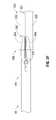
- FIG. 2is an enlarged perspective view of an alternate embodiment of the tunneling system incorporating a coupling with a thread for releasably connecting a catheter;
- FIG. 3Ais a perspective view of another alternate embodiment of the tunneling system including a clamping member with a pair of jaws;
- FIG. 3Bis a side plan view of the tunneling system shown in FIG. 3A with a sheath covering the coupling;
- FIG. 3Cis a side plan view of the tunneling system of FIG. 3A illustrating the jaws of the coupling in the closed position;
- FIG. 3Dis a side plan view of the tunneling system of FIG. 3A illustrating the jaws of the coupling in an open position with a catheter positioned adjacent the coupling;
- FIG. 3Eis a side plan view of the tunneling system of FIG. 3A depicting the jaws of the coupling clasping the catheter;
- FIG. 3Fis a side plan view of the tunneling system of FIG. 3A depicting the jaws of the coupling clasping a septum of the catheter;
- FIG. 4Ais an enlarged perspective view of another embodiment of the tunneling system illustrating a coupling incorporating a pointed end and a barb extending radially therefrom;
- FIG. 4Bis a side plan view of the dual-lumen catheter and the coupling of FIG. 4A separated from each other;
- FIG. 4Cis a side plan view of the dual-lumen catheter and the coupling of FIG. 4A coupled to each other;
- FIG. 5Ais a perspective view of an alternate embodiment of a tunneling system including a coupling having a tapered tip, a peripheral recess, and a compression ring;
- FIG. 5Bis a side plan view of the coupling of FIG. 5A with the tapered tip positioned inside a longitudinal lumen of a catheter;
- FIG. 5Cis a side cross-sectional view of the coupling of FIG. 5A with the compression ring positioned with the peripheral recess;
- FIG. 5Dis a perspective view of another alternate embodiment of the tunneling system including a coupling having a tapered tip, a recess, and a compression sleeve;
- FIG. 5Eis a side plan view of the tunneling system of FIG. 5D with the tapered tip inserted in a longitudinal lumen of the catheter;
- FIG. 5Fis a side plan view of the tunneling system of FIG. 5D with locking detents of the compression sleeve engaging the catheter adjacent the recess;
- FIG. 6Ais a perspective view of another embodiment tunneling system including a coupling having a hook for releasably connecting a dual-lumen catheter;
- FIG. 6Bis a side cross-sectional view of the coupling shown in FIG. 6A attached to the dual-lumen catheter;
- FIG. 7Ais a perspective view of another embodiment of the tunneling system including a coupling having an expansion ring disposed in an annular groove and a tapered tip dimensioned for reception within a longitudinal bore of a catheter;
- FIG. 7Bis a side cross-sectional view of the tunneling system of FIG. 7A and the catheter;
- FIG. 7Cis a side cross-sectional view of the tunneling system of FIG. 7A connected to a catheter;
- FIG. 7Dis a side cross-sectional view of a tunneling system according to another embodiment of the present disclosure.
- FIG. 8is a perspective view of a tunneling system having a pneumatic system configured to hold a portion of the catheter;
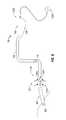
- FIGS. 9-10are front plan views of the chest area of a subject illustrating the steps of a reverse tunneling procedure.
- FIGS. 11-12are front plan views of the chest area of a subject showing the steps of an alternative reverse tunneling procedure.
- the exemplary embodiments of the present disclosureare directed to a tunneling system incorporating a coupling adapted for connection to a catheter.
- the tunneling system of the present disclosuremay have various applications. During a hemodialysis catheter implantation procedure, the tunneling system creates or enlarges a subcutaneous tunnel within a subject and positions a catheter in the target site. It is envisioned, however, that the presently disclosed tunneling system may be employed in other suitable medical procedures. For instance, the tunneling system of the present disclosure may be utilized for subcutaneously implanting a stent, a vascular graft, or the like, inside a subject's body.
- proximalwill refer to the portion of a structure that is closer to a clinician, whereas the term “distal” will refer to the portion that is farther from the clinician.
- FIG. 1Agenerally illustrates the tunneling system 10 of the present disclosure.
- tunneling system 10includes an elongate tunneling member 100 operatively connected to or integrally formed with a coupling 200 .
- the elongate tunneling member 100serves to create or enlarge subcutaneous tunnel within a subject.
- the coupling 200is capable of securely engaging a catheter 300 . Once coupling 200 has been secured to catheter 300 , a clinician can maneuver catheter 300 within the subcutaneous tunnel formed by elongate tunneling member 100 through cooperative movement of the elongate tunneling member 100 .
- tunneling system 10facilitates the placement of the catheter 300 inside a subject at any predetermined location.
- a clinician employing tunneling system 10may use the antegrade and reverse tunneling methods disclosed in U.S. Pat. No. 5,509,897 to Twardowski to situate catheter 300 in the desired location. The entire contents of U.S. Pat. No. 5,509,897 are incorporated by reference herein.
- Elongate tunneling member 100 of tunneling system 10defines a longitudinal axis along at least a portion of a longitudinal length thereof and has first end 102 and second end 104 .
- First end 102 of elongate tunneling member 100is adapted for grasping engagement and handling by a clinician.
- Second end 104 of elongate tunneling member 100incorporates or is connected to coupling 200 , which is connectable to catheter 300 .
- elongate tunneling member 100includes first end 108 configured for passage through tissue to create and/or enlarge a subcutaneous tunnel within a subject, as shown in FIG. 1E .
- First end 108includes offset segment 110 dimensioned to facilitate passage through the subcutaneous tunnel.
- Offset segment 110may incorporate any angular or arcuate arrangement suitable to facilitate insertion and/or passage through the tissue when elongate tunneling member 100 is manipulated by the clinician.
- offset segment 110is obliquely arranged with respect to the longitudinal axis of the elongate tunneling member 100 at a relatively small angle. Other arrangements and angular relationships of offset segment 110 are also envisioned.
- coupling 200includes body 202 dimensioned for reception inside longitudinal bore 302 of catheter 300 .
- Body 202which may have a substantially cylindrical cross-section, includes a tapered distal portion 204 and at least one pin 206 extending radially with respect to coupling 200 .
- Tapered distal portion 204facilitates insertion of coupling 200 within the longitudinal bore 302 of catheter 300 .
- Pins 206are adapted to be received by holes 304 of catheter 300 .
- body 202includes two pins 206 positioned in a diametrically opposed relation to each other.
- body 202may include fewer or more pins arranged in any suitable configuration, insofar as the pins are capable of permanently or temporarily facilitating connection between coupling 200 and catheter 300 .
- body 202may include third pin 206 radially spaced apart from remaining pins 206 , as illustrated in FIG. 1D .
- Third pin 206is also adapted to be received by hole 304 of catheter 300 .
- clinicianinserts at least a portion of body 202 inside longitudinal bore 302 . While the clinician introduces body 202 into longitudinal bore 302 , pins 206 bend to permit insertion of body 202 . When pins 206 are aligned with holes 304 of catheter 300 , the pins 206 return to their original radially outward positions and extend through holes 304 . In this arrangement, coupling 200 establishes a secured coupling with catheter 300 .
- the clinicianmay move or maneuver catheter 300 through a subcutaneous tunnel by controlling the movement of elongate tunneling member 100 .
- another embodiment of tunneling system 10includes a coupling 400 having tapered tip 402 dimensioned for insertion into longitudinal bore 302 of catheter 300 .
- Tapered tip 402defines external thread 404 .
- Thread 404may define a helical configuration and may be relatively sharp to “bite into” the internal surface portions defining longitudinal bore 302 of catheter 300 . As such, thread 404 frictionally engages the internal surfaces portion defining longitudinal bore 302 when inserted into catheter 300 .
- the pitch, shape, and general configuration of tapered tip 402controls the force needed to connect or disconnect coupling 400 from catheter 300 .
- the configuration of tapered tip 402allows the clinician to disconnect coupling 400 from catheter 300 by pulling tunneling member 100 away from catheter 300 .
- Thread 404may alternatively define an undulating configuration to facilitate engagement with the internal surface portions defining longitudinal bore 302 of catheter 300 .
- catheter 300may include an internal thread for engaging thread 404 .
- the clinicianpositions tapered tip 402 within longitudinal bore 302 of catheter 300 .
- the clinicianmay rotate elongate tunneling member 100 during this insertion.
- thread 404frictionally engages or bites the internal surfaces defined by the longitudinal lumen 302 .
- coupling 400secures catheter 300 to elongate tunneling member 100 .
- the cliniciancan maneuver catheter 300 within a subcutaneous tunnel by directing the motion of elongate tunneling member 100 .
- FIGS. 3A-3Eanother embodiment of tunneling system 10 includes coupling 500 located on second end 104 of elongate tunneling member 100 .
- Coupling 500incorporates clamping member 502 configured for holding an end of catheter 300 .
- Clamping member 502contains first and second jaws 504 , 506 which are pivotally connected to each other. Pivot pin 508 , or any other suitable means, connects first jaw 504 to second jaw 506 .
- First jaw 504moves relative to second jaw 506 between an open position (see FIG. 3D ) and a closed position (see FIG. 3E ). In the depicted embodiment, first jaw 504 pivots with respect to second jaw 506 , while second jaw 506 remains stationary.
- clamping member 502may include stationary first jaw 504 and pivotable second jaw 506 , two movable jaws 504 , 506 , or any other suitable apparatus capable of clamping an end of catheter 300 or a portion of a septum internally dividing catheter 300 .
- a protective sheath or wrap 510may cover clamping member 502 to protect coupling 500 from contamination before usage. The clinician may remove wrap 510 before employing tunneling system 10 .
- Any mechanisms for effecting relative pivotal movement of first and second jaws 502 , 504are envisioned including the embodiments disclosed in commonly assigned U.S. Pat. Nos. 5,358,506, 7,087,071 and 7,144,409, the entire contents of each being hereby incorporated herein by reference.
- first and second jaws 504 , 506repositions first and second jaws 504 , 506 from a closed position (see FIG. 3C ) to an open position (see FIG. 3D ). While the jaws 504 , 506 are in the open position, the clinician approximates clamping member 502 to an end of catheter 300 until the end of the catheter 300 is positioned between first and second jaws 504 , 506 , as seen in FIG. 3D . Thereafter, the clinician moves first and second jaws 504 , 506 to the closed position to clamp the end of catheter 300 , as shown in FIG. 3E . At this moment, coupling 500 properly secures elongate tunneling member 100 to catheter 300 .
- the secured interconnection between elongate tunneling member 100 and catheter 300allows the clinician to direct the movement of catheter 300 through elongate tunneling system 100 .
- at least a portion of coupling 500may be inserted within the lumens 303 , 305 of a dual-lumen catheter 300 to secure elongate tunneling member 100 to catheter 300 , as illustrated in FIG. 3F .
- the clinicianintroduces each jaw 504 , 506 inside one lumen 303 , 305 while jaws are located in the open position. Subsequently, the clinician moves jaws 504 , 506 to the closed position to grasp septum 301 dividing lumens 303 , 305 of catheter 300 .
- FIGS. 4A-4Cillustrate another embodiment of the present disclosure.
- Coupling 600is configured for connection to dual-lumen catheter 1300 .
- Dual-lumen catheter 1300includes first lumen 1302 and second lumen 1304 extending along at least a portion of the length thereof. Septum 1306 divides first and second longitudinal bores 1302 , 1304 .
- first longitudinal bore 1302has sealed proximal end 1308
- second longitudinal bore 1304has opening 1312 on the proximal end 1310 thereof.
- Dual-lumen catheter 1304additionally includes abutments walls 1314 adapted to support annular supporting wall 610 of coupling 600 and hole 1316 dimensioned to receive barb 604 of coupling 600 .
- Coupling 600includes at least one barb 604 extending radially therefrom and pointed end 602 for facilitating insertion into second lumen 1304 of dual-lumen catheter 1300 .
- Pointed end 602includes proximal end 606 and distal end 608 and has a frustoconical shape.
- the cross-section of distal end 608 of pointed end 602is larger than the cross-section of proximal end 606 .
- the cross-section of proximal end 606 of pointed end 602is larger than the cross-section of elongate tunneling member 100 .
- Proximal end 606 of pointed end 602defines an annular supporting wall 610 adapted to abut at least one abutment wall 1314 of dual-lumen catheter 1300 .
- Barb 604is located proximally with respect to proximal end 606 of pointed end 602 and is dimensioned for reception within hole 1316 of dual-lumen catheter 1300 .
- coupling 600securely connects elongate tunneling member 100 to dual-lumen catheter 1300 .
- a cliniciancouples elongate tunneling member 100 to dual-lumen catheter 1300 by inserting coupling 600 into second longitudinal lumen 1304 through opening 1312 .
- supporting wall 610engages abutment walls 1314 and barb 604 protrudes out of dual-lumen catheter 1300 through hole 1316 .
- barb 604passes through hole 1316 and supporting wall 610 adjoins abutment walls 1314
- coupling 600securely couples dual-lumen catheter 1300 to elongate tunneling member 100 .
- the cliniciancan then dictate the movement of dual-lumen catheter 1300 through elongate tunneling member 100 .
- another embodiment of elongate tunneling member 100includes coupling 700 for attaching catheter 300 to elongate tunneling member 100 using compression forces.
- the force needed to connect coupling 700 to catheter 300is less than the force required to disconnect coupling 700 from catheter 300 .
- Coupling 700is located on the second longitudinal end 104 of elongate tunneling member 100 and incorporates compression ring 702 , recess 704 and tapered end 706 .
- Compression ring 702is biased inwardly toward the longitudinal axis of elongate tunneling member 100 and is slidably positioned on second longitudinal end 104 of elongate tunneling member 100 .
- Recess 704is located proximally with respect to tapered end 706 and is adapted to receive compression ring 702 .
- Tapered end 706assists in the insertion of coupling 700 into the longitudinal bore 302 of catheter 300 .
- a clinicianconnects elongate tunneling member 100 to catheter 300 by initially positioning coupling 700 inside longitudinal bore 302 .
- at least a portion of recess 704has to be situated in longitudinal bore 302 .
- the clinicianslides compression ring 702 toward catheter 300 .
- compression ring 702travels along a portion of the outer surface 306 of catheter 300 until it reaches recess 704 .
- recess 704it compresses a portion of outer surface 306 of catheter 300 against recess 704 , thereby securing catheter 300 to elongate tunneling member 100 through coupling 700 .
- the cliniciancan maneuver catheter 300 by controlling the movement of elongate tunneling member 100 .
- second longitudinal end 104 of elongate tunneling member 100includes coupling 800 adapted to compress a portion of catheter 300 .
- Coupling 800contains recess 804 , tapered end 806 , and compression sleeve 802 slidably positioned on the elongate tunneling member 100 .
- Tapered end 806has frustoconical shape and facilitates the insertion of coupling 800 into longitudinal bore 302 of catheter 300 .
- Recess 804is dimensioned to receive at least a portion of compression sleeve 802 and at least a portion of catheter 300 .
- Compression sleeve 802contains collar 808 and a plurality of axially extending legs 810 .
- Each leg 810has proximal end 812 and distal end 814 .
- Distal ends 814 of each leg 810have pressing portions or detents 816 for compressing a portion of a catheter 300 against recess 804 .
- Each distal end 814is inwardly biased toward the longitudinal axis of elongate tunneling member 100 .
- compression sleeve 802may have other components.
- compression sleeve 802may include a cylindrical elongate structure extending from collar 808 and having inwardly biased detents at a distal end thereof.
- the clinicianintroduces at least tapered end 806 and recess 805 inside longitudinal bore 302 of catheter 300 . Subsequently, the clinician slides compression sleeve 802 toward the recess 804 . As compression sleeve 802 moves toward recess 804 , detents 816 move along a portion of the outer surface 306 of catheter 300 until they reach the recess 804 . When detents 816 reach recess 804 , the detents 816 move inwardly toward the recess 804 and press a portion of the outer surface 306 of catheter 300 .
- detents 816The compression exerted by detents 816 on the portion of outer surface 306 adjacent to recess 804 effectively secures catheter 300 to elongate tunneling member 100 .
- the clinicianmay control the movement of catheter 300 through elongate tunneling member 100 .
- an alternative embodiment of elongate tunneling member 100includes coupling 900 located on second longitudinal end thereof 104 .
- Coupling 900is adapted to connect elongate tunneling member 100 to a dual-lumen catheter 1400 .
- Dual-lumen catheter 1400includes septum 1406 separating first and second longitudinal lumens 1402 , 1404 .
- Septum 1406extends along the length of dual-lumen catheter 1400 and includes aperture 1408 located on proximal portion 1410 thereof.
- Aperture 1408forms a passage between first and second longitudinal lumens 1402 , 1404 and is dimensioned to receive hook 902 of coupling 900 .
- Coupling 900further includes rod 906 with hook 902 positioned at distal end 904 of rod 906 .
- Rod 906includes distal tip 908 and its cross-section is smaller than the cross-section of elongate tunneling member 100 .
- the cross-section of rod 906is dimensioned for reception within at least one of the longitudinal lumens 1402 , 1404 of dual-lumen catheter 1400 .
- Hook 902extends radially from rod 906 and is configured to be received in aperture 1408 of dual-lumen catheter 1400 . Additionally, hook 902 defines an acute angle with respect to the longitudinal axis of rod 906 .
- a clinicianpositions rod 906 in either of the longitudinal lumens 1402 , 1404 of catheter 1400 . While rod 906 enters the longitudinal lumen 1402 , 1404 , hook 902 passes through aperture 1408 thereby coupling elongate tunneling member 100 to dual-lumen catheter 1400 . Then, the clinician can maneuver dual-lumen catheter 1400 through a subcutaneous tunnel by directing the movement of elongate tunneling member 100 .
- tunneling member 100incorporates coupling 1000 for connecting elongate tunneling member 100 to catheter 300 by applying pressure to an inner surface 308 of catheter 300 .
- Coupling 1000is disposed adjacent second longitudinal end 104 of elongate tunneling member 100 and includes lumen 1008 extending therethrough, tapered distal tip 1002 , expanding ring 1004 , and annular groove 1006 adapted to receive the expanding ring 1002 .
- Tapered distal tip 1002is located distally with respect to annular groove 1006 and assists the insertion of coupling 1000 into longitudinal bore 302 of catheter 300 .
- Annular groove 1006spans the circumference of coupling 1000 and is configured to receive expanding ring 1004 .
- Expanding ring 1004is securely positioned in annular groove 1006 but is biased outwardly relative to the longitudinal axis of elongate tunneling member 100 .
- Expanding ring 1004may be fabricated from a suitable elastomer, foam, bladder, etc. It is further envisioned that expandable ring may be adapted to swell in the presence of liquids, e.g., have absorption characteristics which causes ring 1004 to expand when exposed to fluids such as blood or other bodily fluids.
- Lumen 1008may be used to flush catheter 300 subsequent to mounting to the catheter 300 and may be in fluid communication with a fluid source. Fluid flow is represented schematically as flow “F”. It is further envisioned that the fluids transferred through lumen 1008 may assist in the expansion of expanding ring 1004 .
- the clinicianinserts coupling 1000 into longitudinal bore 302 of catheter 300 . While coupling 1000 advances through longitudinal bore 302 , expanding ring 1004 applies pressure to the inner surface 308 of catheter 300 . The pressure applied to inner surface 308 by expanding ring 1004 establishes a secured relation between elongate tunneling member 100 and catheter 300 . Once catheter 300 has been properly secured to elongate tunneling member 100 , the clinician can maneuver catheter 300 through elongate tunneling member 100 .
- coupling 1000incorporates an inflatable member or balloon 1005 in lieu of expanding ring 1004 .
- Inflatable balloon 1005may be disposed within annular groove 1006 , or, in the absence of the groove 1006 , mounted about the outer surface of the coupling 1000 .
- Inflatable member 1005is in fluid communication with lumen 1008 extending the length of tunneling member 100 .
- the clinicianintroduces coupling 1000 within catheter 300 .
- fluidis passed through lumen 1008 to inflate inflatable member 1005 . (see phantom lines)
- inflatable member 1005expands, the outer surfaces of inflatable member 1005 engage the inner surfaces of catheter 300 , thereby securing tunneling member 100 to catheter 300 .
- an embodiment of tunneling system 10contains pneumatic system 1200 configured to hold catheter 300 .
- Pneumatic system 1200includes suction source 1202 operatively connected to elongate tunneling member 100 and a plurality of ports 1204 disposed about coupling 1100 .
- a tube 1206or any other suitable apparatus, interconnects suction source 1202 and elongate tunneling member 100 , and maintains fluid communication between suction source 1202 and a longitudinal bore 101 (shown in phantom) extending through elongate tunneling member 100 .
- Elongate tunneling member 100includes handle 106 on its first longitudinal end 102 and coupling 1100 on its second longitudinal end 104 .
- Coupling 1100incorporates ports 1204 and is dimensioned for reception within longitudinal bore 302 of catheter 300 . Ports 1204 are in fluid communication with the longitudinal bore (not shown) of elongate tunneling member 100 and suction source 1202 . During use, suction source 1202 supplies suction force to pneumatic system 1200 .
- the clinicianinitially positions coupling 1110 along with ports 1204 inside longitudinal bore 302 of catheter 300 . Then, the clinician turns on suction source 1202 to provide ports 1202 with the suction force needed to hold catheter 300 .
- suction source 1202When suction source 1202 is activated, pneumatic system 1200 sucks fluid from within catheter 300 through ports 1204 and the suction forces exerted in longitudinal bore 302 draw the internal wall surfaces of the catheter 300 onto coupling 1110 to thereby secure the catheter 300 to elongate tunneling member 100 .
- tunneling system 10creates or enlarges a subcutaneous tunnel for deploying any suitable catheter inside the right atrium through the right jugular vein.
- the catheter 2000may be implanted in the right atrium via the left jugular vein, the right atrium through the right subclavian vein, the right atrium through the left subclavian vein, or implanted in the femoral vein of the subject.
- the internal jugular vein 1502is punctured using known techniques.
- a guide wiremay be positioned to access the heart to facilitate insertion of the leading end 2080 of catheter 2000 within the heart through techniques known in the art.
- An entry opening or venotomy 1500is made above the clavicle, through the skin and the subcutaneous tissue.
- Distal end 2080 of catheter 2000is inserted through the internal jugular vein 1502 , the superior vena cava 1504 and into the right atrium 1506 .
- the positioning of leading end 2080 of catheter 2000may be confirmed with an x-ray if desired.
- Proximal trailing end 2100 of the catheter 2000may extend from the venotomy site 1500 .
- Exit opening 1508is made adjacent to the chest wall below the venotomy site 1500 to define one base of the tunnel.
- an optional dilator elementmay be mounted to the tunneling system 10 .
- Offset segment 108 of tunneling system 10may be introduced within the venotomy site 1500 and advanced toward exit opening 1508 .
- the dilator elementengages internal tissue beneath the venotomy site 1500 .
- An enlarged tissue tractis thereby made to create a shelf for accommodating a cuff of the catheter by advancing the dilation element a predetermined distance through the venotomy site 1500 toward the exit opening 508 .
- the predetermined distancecorresponding to the desired location of the cuff 210 .
- Tunneling system 10is then retracted to the venotomy site 1500 and the dilator element is removed from the tunneling system 10 .
- coupling 200is then connected to the catheter 2000 to secure the catheter 200 to the tunneling system 10 .
- tunneling system 10is readvanced in the direction of directional arrow “j” from the venotomy site 1500 toward the exit opening 1508 until the ends of catheter 2000 is exposed from the exit opening 1508 .
- the relatively small profile of the coupling 200facilitates passage of the coupling 200 through tissue.
- the catheter 2000is removed from its mounting to tunneling system 10 and assembled in order to be connected to a hemodialysis machine.
- catheter 2000is released from its mounting to coupling 200 by exerting a linear force on catheter 2000 .
- the catheter 2000is severed or cut adjacent the coupling 200 to expose the catheter ends.
- clinicianmay also perform an alternative reverse tunneling procedure with elongate tunneling system 10 .
- the clinicianpunctures the internal jugular vein 1502 with any conventional surgical tool.
- a guide wiremay be positioned to access the heart to facilitate insertion of the leading end 2080 of catheter 20000 within the heart through techniques known in the art.
- the clinicianmakes an entry opening or venotomy 1500 above the clavicle.
- the entry opening 1500should extend through the skin and the subcutaneous tissue of the subject.
- the clinicianinserts the leading end 2080 of the catheter 2000 in the right atrium 1506 as explained above for the other reverse tunneling procedure.
- the trailing end 2100 of the catheter 2000may extend from the venotomy site 1500 .
- the cliniciancreates an exit opening 1508 below the venotomy site 1500 .
- the exit opening 1508should extend through the skin and the subcutaneous tissue of the subject.
- the clinicianmay place releasable cover 1600 over the coupling 200 of the elongate tunneling system 10 .
- the cliniciansubsequently grabs the elongate tunneling system 10 by the handle 1602 and advances the elongate tunneling system 10 from the exit opening 1508 toward the entry opening 1500 as indicated by arrow “b.” While the clinician moves the elongate tunneling system 10 from exit opening 1508 toward entry opening 1500 , the elongate tunneling member 100 creates or enlarges a subcutaneous tunnel between the two openings.
- the clinicianmay subcutaneously advance elongate tunneling member 10 until the releasable cover 1600 is exposed through entry opening 1500 . Afterwards, the clinician removes the releasable cover 1600 and couples the trailing end 2100 of the catheter 2000 to the elongated tunneling system 10 with coupling 200 .
- the elongate tunneling system 10is the retracted, along with the catheter 200 , from the entry opening 1500 toward the exit opening 1508 , in the direction indicated by arrow “j,” until the trailing end 2100 of the catheter 2000 is exposed through exit opening 1508 .
- the catheter 2000is removed from its mounting to tunneling system 10 and assembled to be connected to a hemodialysis machine.
- catheter 2000is released from its mounting to coupling 200 by exerting a linear force on catheter 2000 .
- the catheter 2000is severed or cut adjacent the coupling 200 to expose the catheter ends. Further details of the reverse tunneling procedures may be ascertained by reference to U.S. patent application Ser. No. 12/041,422, filed Mar. 3, 2008, the entire contents of which is hereby incorporated by reference herein.
Landscapes
- Health & Medical Sciences (AREA)
- Life Sciences & Earth Sciences (AREA)
- Veterinary Medicine (AREA)
- Animal Behavior & Ethology (AREA)
- Engineering & Computer Science (AREA)
- Biomedical Technology (AREA)
- Heart & Thoracic Surgery (AREA)
- Public Health (AREA)
- General Health & Medical Sciences (AREA)
- Surgery (AREA)
- Molecular Biology (AREA)
- Medical Informatics (AREA)
- Nuclear Medicine, Radiotherapy & Molecular Imaging (AREA)
- Biophysics (AREA)
- Pulmonology (AREA)
- Anesthesiology (AREA)
- Hematology (AREA)
- Media Introduction/Drainage Providing Device (AREA)
Abstract
Description
Claims (6)
Priority Applications (1)
| Application Number | Priority Date | Filing Date | Title |
|---|---|---|---|
| US12/206,391US8979744B2 (en) | 2008-09-08 | 2008-09-08 | Tunneling system |
Applications Claiming Priority (1)
| Application Number | Priority Date | Filing Date | Title |
|---|---|---|---|
| US12/206,391US8979744B2 (en) | 2008-09-08 | 2008-09-08 | Tunneling system |
Publications (2)
| Publication Number | Publication Date |
|---|---|
| US20100063513A1 US20100063513A1 (en) | 2010-03-11 |
| US8979744B2true US8979744B2 (en) | 2015-03-17 |
Family
ID=41799887
Family Applications (1)
| Application Number | Title | Priority Date | Filing Date |
|---|---|---|---|
| US12/206,391Active2032-09-01US8979744B2 (en) | 2008-09-08 | 2008-09-08 | Tunneling system |
Country Status (1)
| Country | Link |
|---|---|
| US (1) | US8979744B2 (en) |
Cited By (10)
| Publication number | Priority date | Publication date | Assignee | Title |
|---|---|---|---|---|
| US20140088564A1 (en)* | 2012-09-24 | 2014-03-27 | James Augustine | Tunneler device including a separation prevention device |
| USD746445S1 (en)* | 2014-06-27 | 2015-12-29 | Harrison M. Lazarus | Placement tool for a body cavity drainage device |
| US10029036B2 (en) | 2014-06-27 | 2018-07-24 | Merit Medical Systems, Inc. | Placement tools for body cavity drainage devices and related methods |
| US10232150B2 (en) | 2010-03-11 | 2019-03-19 | Merit Medical Systems, Inc. | Body cavity drainage devices and related methods |
| US10286183B2 (en) | 2015-11-25 | 2019-05-14 | Merit Medical Systems, Inc. | Steerable sheath catheter and methods of use |
| USD861858S1 (en)* | 2017-10-25 | 2019-10-01 | Terumo Kabushiki Kaisha | Catheter |
| USD870880S1 (en)* | 2018-05-29 | 2019-12-24 | Device Therapeutics, Inc. | Indwelling catheter with an archimedean spiral |
| US11058806B2 (en) | 2014-06-27 | 2021-07-13 | The Seaberg Company, Inc. | Body cavity drainage devices including drainage tubes having inline portions and related methods |
| US11559662B2 (en) | 2018-04-13 | 2023-01-24 | Merit Medical Systems, Inc. | Steerable drainage devices |
| USD990677S1 (en)* | 2018-10-30 | 2023-06-27 | Hi-Lex Corporation | Medical tunneling instrument |
Families Citing this family (8)
| Publication number | Priority date | Publication date | Assignee | Title |
|---|---|---|---|---|
| EP2451512A1 (en) | 2009-07-07 | 2012-05-16 | C.R. Bard Inc. | Extensible internal bolster for a medical device |
| US9308013B2 (en) | 2010-11-03 | 2016-04-12 | Gyrus Ent, L.L.C. | Surgical tool with sheath |
| US20140188148A1 (en) | 2012-12-27 | 2014-07-03 | Pieter W.C.J. le Blanc | Surgical tunneler |
| AU2015204805B2 (en)* | 2014-01-09 | 2018-10-25 | Hollister Incorporated | Catheter cartridge assemblies and methods of using the same for intermittent catheterization |
| JP6286688B2 (en)* | 2014-03-28 | 2018-03-07 | テルモ・クリニカルサプライ株式会社 | Subcutaneous penetration tool for catheter guidance |
| EP3215211A4 (en) | 2014-11-07 | 2018-07-04 | C. R. Bard, Inc. | Connection system for tunneled catheters |
| US11896782B2 (en) | 2017-08-23 | 2024-02-13 | C. R. Bard, Inc. | Priming and tunneling system for a retrograde catheter assembly |
| FR3103109B1 (en) | 2019-11-18 | 2024-11-29 | Novaflow | Bidirectional arterial cannula for extracorporeal membrane oxygenation and method of using such a cannula |
Citations (74)
| Publication number | Priority date | Publication date | Assignee | Title |
|---|---|---|---|---|
| US4299228A (en) | 1979-07-11 | 1981-11-10 | Peters Joseph L | Safety device for use with a cannula |
| US4490136A (en) | 1981-10-14 | 1984-12-25 | Aktiebolaget Meteve | Trocar |
| US4574806A (en)* | 1984-10-01 | 1986-03-11 | Cordis Corporation | Tunnelling device for peripheral vascular reconstruction |
| US4674496A (en) | 1986-09-30 | 1987-06-23 | Albert Einstein College Of Medicine Of Yeshiva University | Double-lumen tube adaptor |
| US4705041A (en) | 1984-07-06 | 1987-11-10 | Kim Il G | Dilator for Sphincter of Oddi |
| US4819694A (en) | 1987-09-21 | 1989-04-11 | Ling Nan Flexible & Shaft Factory Of Guang Zhou | Water control valve |
| US4832687A (en) | 1987-12-31 | 1989-05-23 | Smith Iii Ray C | Subcutaneous tunneling instrument and method |
| US5059170A (en) | 1990-02-02 | 1991-10-22 | Mallinckrodt Medical, Inc. | Connection adapter for catheters |
| US5129891A (en) | 1989-05-19 | 1992-07-14 | Strato Medical Corporation | Catheter attachment device |
| US5207643A (en) | 1991-05-08 | 1993-05-04 | Ballard Medical Products | Multi-lumen-catheter flow valve system |
| US5209723A (en) | 1990-01-08 | 1993-05-11 | The Curators Of The University Of Missouri | Multiple lumen catheter for hemodialysis |
| US5279597A (en) | 1992-01-13 | 1994-01-18 | Arrow International Investment Corp. | Catheter compression clamp |
| US5358506A (en) | 1991-03-14 | 1994-10-25 | United States Surgical Corporation | Approximating apparatus for surgical jaw structure |
| US5405320A (en) | 1990-01-08 | 1995-04-11 | The Curators Of The University Of Missouri | Multiple lumen catheter for hemodialysis |
| US5478318A (en) | 1990-07-26 | 1995-12-26 | Yoon; Inbae | Multiluminal endoscopic portal |
| US5562618A (en) | 1994-01-21 | 1996-10-08 | Sims Deltec, Inc. | Portal assembly and catheter connector |
| US5624413A (en) | 1996-02-23 | 1997-04-29 | Medical Components, Inc. | Method for inserting a multiple catheter assembly |
| US5637102A (en) | 1995-05-24 | 1997-06-10 | C. R. Bard, Inc. | Dual-type catheter connection system |
| US5718678A (en) | 1996-06-26 | 1998-02-17 | Medical Components, Inc. | Multi-lumen coaxial catheter and method for making same |
| US5797869A (en)* | 1987-12-22 | 1998-08-25 | Vas-Cath Incorporated | Multiple lumen catheter |
| US5944732A (en) | 1997-08-27 | 1999-08-31 | Medical Components, Inc. | Subcutaneous tunnelling device and methods of forming a subcutaneous tunnel |
| US6099519A (en) | 1994-07-29 | 2000-08-08 | Tyco Healthcare Group Lp | Catheter sleeve connecting assembly |
| US6113572A (en) | 1995-05-24 | 2000-09-05 | C. R. Bard, Inc. | Multiple-type catheter connection systems |
| US6126631A (en) | 1994-04-04 | 2000-10-03 | Wake Forest University | Multi-lumen catheter system used in a blood treatment process |
| US6423053B1 (en) | 2000-01-12 | 2002-07-23 | Han-Pin Lee | Releasable tube assembly |
| US6453185B1 (en) | 2000-03-17 | 2002-09-17 | Integra Lifesciences, Inc. | Ventricular catheter with reduced size connector and method of use |
| US6638242B2 (en) | 2001-01-24 | 2003-10-28 | Jon S. Wilson | Multi-lumen catheter with attachable hub |
| US20040034324A1 (en) | 2002-08-19 | 2004-02-19 | Seese Timothy M. | User-friendly catheter connection adapters for optimized connection to multiple lumen catheters |
| US20040044330A1 (en)* | 2002-02-19 | 2004-03-04 | Changqing Li | Medical catheter assembly including multi-piece connector |
| US20040167478A1 (en) | 1996-11-26 | 2004-08-26 | Mooney Charles R. | Multiple lumen access device having a multifunction adapter and method of use |
| US20040171997A1 (en) | 2001-01-24 | 2004-09-02 | Wilson Jon S. | Double-y-shaped multi-lumen catheter with selectively attachable hubs |
| US20040176788A1 (en)* | 2003-03-07 | 2004-09-09 | Nmt Medical, Inc. | Vacuum attachment system |
| US20040176739A1 (en) | 2002-12-18 | 2004-09-09 | John Stephens | Catheter tunneler and adapter |
| US20040210187A1 (en)* | 2002-02-07 | 2004-10-21 | Zawacki John A. | Split tip dialysis catheter |
| USD498844S1 (en) | 2003-08-29 | 2004-11-23 | C. R. Bard, Inc. | Dual lumen catheter winged bifurcation |
| US6858019B2 (en) | 2001-01-09 | 2005-02-22 | Rex Medical, L.P. | Dialysis catheter and methods of insertion |
| US20050085765A1 (en) | 2003-10-20 | 2005-04-21 | Medical Components, Inc. | Multi-lumen catheter |
| US20050107770A1 (en) | 2003-11-19 | 2005-05-19 | Medical Components, Inc. | Luer with integrated clamp |
| US20050137580A1 (en) | 2003-12-19 | 2005-06-23 | Medical Components, Inc. | Catheter button hub |
| US6911014B2 (en) | 2001-10-05 | 2005-06-28 | Medical Components, Inc. | Continuous flow peritoneal dialysis catheter |
| US6916051B2 (en) | 2003-02-13 | 2005-07-12 | Medical Components, Inc. | Coupler for a flexible tube |
| US6921396B1 (en) | 2002-08-30 | 2005-07-26 | Arrow International, Inc. | Multi-lumen catheter with integrated connector |
| US6939328B2 (en) | 2002-02-27 | 2005-09-06 | Medical Components, Inc. | Dissolvable subcutaneous catheter cover |
| US20050209584A1 (en) | 2004-03-18 | 2005-09-22 | Guy Rome | Multifunction adaptor for an open-ended catheter |
| US20050209583A1 (en) | 2004-03-18 | 2005-09-22 | Powers Kelly B | Connector system for a proximally trimmable catheter |
| US20050228364A1 (en) | 2004-04-09 | 2005-10-13 | Richard Braga | Tunneler device |
| US20050256461A1 (en)* | 2004-05-12 | 2005-11-17 | Difiore Attilio E | Catheter with removable extension |
| US20050261665A1 (en) | 2002-12-18 | 2005-11-24 | Medical Components, Inc. | Method of using a multi-lumen catheter |
| US6979339B2 (en) | 2001-10-25 | 2005-12-27 | Smiths Group Plc | Medico-surgical instruments |
| US20060009783A1 (en) | 2004-07-08 | 2006-01-12 | Guy Rome | Tunneler with gripping mechanisms |
| US20060015086A1 (en) | 2004-04-01 | 2006-01-19 | Kelly Rasmussen | Catheter connector system |
| US20060015130A1 (en)* | 2004-07-14 | 2006-01-19 | Medical Components, Inc. | Catheter tunneler adapter |
| US7008395B1 (en) | 1994-04-04 | 2006-03-07 | Wake Forset University Health Sciences | Multi-lumen catheter system used in a blood treatment process |
| US20060095062A1 (en) | 2004-11-01 | 2006-05-04 | Medical Components, Inc. | Universal catheter tunneler |
| US20060135949A1 (en) | 2004-12-21 | 2006-06-22 | Rome Guy T | Tunneler with an expandable attachment mechanism |
| US7087071B2 (en) | 1992-02-12 | 2006-08-08 | United States Surgical Corporation | Articulating endoscopic surgical apparatus |
| US20060224110A1 (en) | 2005-03-17 | 2006-10-05 | Scott Michael J | Methods for minimally invasive vascular access |
| US7128734B1 (en) | 2002-09-20 | 2006-10-31 | Arrow International, Inc. | Apparatus and method for reverse tunneling a multi-lumen catheter in a patient |
| US7144409B2 (en) | 2001-03-05 | 2006-12-05 | Tyco Healthcare Group Lp | Surgical grasping instrument |
| US20060276773A1 (en) | 2001-01-24 | 2006-12-07 | Wilson Jon S | Multi-lumen catheter with attachable hub |
| US20070016167A1 (en) | 2005-03-29 | 2007-01-18 | Smith A D | Implantable cathether and method of using same |
| US20070060866A1 (en) | 2002-10-31 | 2007-03-15 | Medical Components, Inc. | Method of attaching a hub to a multiple catheter assembly |
| US20070078396A1 (en)* | 2005-09-16 | 2007-04-05 | Kristin Feeley | Tunneler for use dual lumen tip catheter |
| US7261708B2 (en) | 2002-10-31 | 2007-08-28 | Medical Components, Inc. | Removable catheter hub |
| US20070260221A1 (en) | 2006-05-05 | 2007-11-08 | Medical Components, Inc. | Hub for triple lumen catheter assembly |
| US20070265597A1 (en) | 2003-07-17 | 2007-11-15 | Timothy Schweikert | Catheter Tunneler adapter |
| US20070282274A1 (en) | 2006-06-02 | 2007-12-06 | Medical Components, Inc. | Catheter tunneler |
| US20080009832A1 (en) | 2005-06-20 | 2008-01-10 | C. R. Bard, Inc. | Connection system for multi-lumen catheter |
| US20080051863A1 (en)* | 2003-07-25 | 2008-02-28 | Integrated Sensing Systems, Inc. | Method and anchor for medical implant placement, and method of anchor manufacture |
| US20080086161A1 (en) | 2006-05-05 | 2008-04-10 | I-Flow Corporation | Soft tissue tunneling device |
| US20080097409A1 (en) | 2006-10-19 | 2008-04-24 | Medical Components, Inc. | Catheter tunneler adapter and methods of assembly to a catheter and use |
| US20080214992A1 (en) | 2007-03-02 | 2008-09-04 | Brett Haarala | Catheter tunneling systems, instruments and methods |
| US7578803B2 (en)* | 2004-03-18 | 2009-08-25 | C. R. Bard, Inc. | Multifunction adaptor for an open-ended catheter |
| US7955318B1 (en)* | 2004-07-16 | 2011-06-07 | Schultz Joseph P | Multipurpose large bore medical suction systems |
Family Cites Families (1)
| Publication number | Priority date | Publication date | Assignee | Title |
|---|---|---|---|---|
| US6363381B1 (en)* | 1998-11-03 | 2002-03-26 | Ricoh Co., Ltd. | Compressed document matching |
- 2008
- 2008-09-08USUS12/206,391patent/US8979744B2/enactiveActive
Patent Citations (85)
| Publication number | Priority date | Publication date | Assignee | Title |
|---|---|---|---|---|
| US4299228A (en) | 1979-07-11 | 1981-11-10 | Peters Joseph L | Safety device for use with a cannula |
| US4490136A (en) | 1981-10-14 | 1984-12-25 | Aktiebolaget Meteve | Trocar |
| US4705041A (en) | 1984-07-06 | 1987-11-10 | Kim Il G | Dilator for Sphincter of Oddi |
| US4574806A (en)* | 1984-10-01 | 1986-03-11 | Cordis Corporation | Tunnelling device for peripheral vascular reconstruction |
| US4674496A (en) | 1986-09-30 | 1987-06-23 | Albert Einstein College Of Medicine Of Yeshiva University | Double-lumen tube adaptor |
| US4819694A (en) | 1987-09-21 | 1989-04-11 | Ling Nan Flexible & Shaft Factory Of Guang Zhou | Water control valve |
| US5797869A (en)* | 1987-12-22 | 1998-08-25 | Vas-Cath Incorporated | Multiple lumen catheter |
| US4832687A (en) | 1987-12-31 | 1989-05-23 | Smith Iii Ray C | Subcutaneous tunneling instrument and method |
| US5129891A (en) | 1989-05-19 | 1992-07-14 | Strato Medical Corporation | Catheter attachment device |
| US5509897A (en) | 1990-01-08 | 1996-04-23 | The Curators Of The University Of Missouri | Multiple lumen catheter for hemodialysis |
| US5209723A (en) | 1990-01-08 | 1993-05-11 | The Curators Of The University Of Missouri | Multiple lumen catheter for hemodialysis |
| US5405320A (en) | 1990-01-08 | 1995-04-11 | The Curators Of The University Of Missouri | Multiple lumen catheter for hemodialysis |
| US5059170A (en) | 1990-02-02 | 1991-10-22 | Mallinckrodt Medical, Inc. | Connection adapter for catheters |
| US5478318A (en) | 1990-07-26 | 1995-12-26 | Yoon; Inbae | Multiluminal endoscopic portal |
| US5358506A (en) | 1991-03-14 | 1994-10-25 | United States Surgical Corporation | Approximating apparatus for surgical jaw structure |
| US5207643A (en) | 1991-05-08 | 1993-05-04 | Ballard Medical Products | Multi-lumen-catheter flow valve system |
| US5505714A (en) | 1992-01-13 | 1996-04-09 | Arrow International Investment Corp. | Non-rotational catheter compression clamp |
| US5279597A (en) | 1992-01-13 | 1994-01-18 | Arrow International Investment Corp. | Catheter compression clamp |
| US7087071B2 (en) | 1992-02-12 | 2006-08-08 | United States Surgical Corporation | Articulating endoscopic surgical apparatus |
| US5562618A (en) | 1994-01-21 | 1996-10-08 | Sims Deltec, Inc. | Portal assembly and catheter connector |
| US5613945A (en) | 1994-01-21 | 1997-03-25 | Sims Deltec, Inc. | Portal assembly |
| US5632729A (en) | 1994-01-21 | 1997-05-27 | Sims Deltec, Inc. | Catheter connector |
| US5743873A (en) | 1994-01-21 | 1998-04-28 | Sims Deltec, Inc. | Methods for using catheter connectors and portals, and methods of assembly |
| US7008395B1 (en) | 1994-04-04 | 2006-03-07 | Wake Forset University Health Sciences | Multi-lumen catheter system used in a blood treatment process |
| US6126631A (en) | 1994-04-04 | 2000-10-03 | Wake Forest University | Multi-lumen catheter system used in a blood treatment process |
| US6099519A (en) | 1994-07-29 | 2000-08-08 | Tyco Healthcare Group Lp | Catheter sleeve connecting assembly |
| US5637102A (en) | 1995-05-24 | 1997-06-10 | C. R. Bard, Inc. | Dual-type catheter connection system |
| US6113572A (en) | 1995-05-24 | 2000-09-05 | C. R. Bard, Inc. | Multiple-type catheter connection systems |
| US5624413A (en) | 1996-02-23 | 1997-04-29 | Medical Components, Inc. | Method for inserting a multiple catheter assembly |
| US5718678A (en) | 1996-06-26 | 1998-02-17 | Medical Components, Inc. | Multi-lumen coaxial catheter and method for making same |
| US20040167478A1 (en) | 1996-11-26 | 2004-08-26 | Mooney Charles R. | Multiple lumen access device having a multifunction adapter and method of use |
| US5944732A (en) | 1997-08-27 | 1999-08-31 | Medical Components, Inc. | Subcutaneous tunnelling device and methods of forming a subcutaneous tunnel |
| US6423053B1 (en) | 2000-01-12 | 2002-07-23 | Han-Pin Lee | Releasable tube assembly |
| US6453185B1 (en) | 2000-03-17 | 2002-09-17 | Integra Lifesciences, Inc. | Ventricular catheter with reduced size connector and method of use |
| US6858019B2 (en) | 2001-01-09 | 2005-02-22 | Rex Medical, L.P. | Dialysis catheter and methods of insertion |
| US6872198B1 (en) | 2001-01-24 | 2005-03-29 | Arrow International, Inc. | Double-y-shaped multi-lumen catheter with selectively attachable hubs |
| US7300430B2 (en) | 2001-01-24 | 2007-11-27 | Arrow International, Inc. | Multi-lumen catheter with attachable hub |
| US20040171997A1 (en) | 2001-01-24 | 2004-09-02 | Wilson Jon S. | Double-y-shaped multi-lumen catheter with selectively attachable hubs |
| US20060276773A1 (en) | 2001-01-24 | 2006-12-07 | Wilson Jon S | Multi-lumen catheter with attachable hub |
| US20040065333A1 (en) | 2001-01-24 | 2004-04-08 | Wilson Jon S. | Multi-lumen catheter with attachable hub |
| US6638242B2 (en) | 2001-01-24 | 2003-10-28 | Jon S. Wilson | Multi-lumen catheter with attachable hub |
| US7144409B2 (en) | 2001-03-05 | 2006-12-05 | Tyco Healthcare Group Lp | Surgical grasping instrument |
| US6911014B2 (en) | 2001-10-05 | 2005-06-28 | Medical Components, Inc. | Continuous flow peritoneal dialysis catheter |
| US6979339B2 (en) | 2001-10-25 | 2005-12-27 | Smiths Group Plc | Medico-surgical instruments |
| US20040210187A1 (en)* | 2002-02-07 | 2004-10-21 | Zawacki John A. | Split tip dialysis catheter |
| US20040044330A1 (en)* | 2002-02-19 | 2004-03-04 | Changqing Li | Medical catheter assembly including multi-piece connector |
| US6939328B2 (en) | 2002-02-27 | 2005-09-06 | Medical Components, Inc. | Dissolvable subcutaneous catheter cover |
| US20040034324A1 (en) | 2002-08-19 | 2004-02-19 | Seese Timothy M. | User-friendly catheter connection adapters for optimized connection to multiple lumen catheters |
| US7163531B2 (en) | 2002-08-19 | 2007-01-16 | Baxter International, Inc. | User-friendly catheter connection adapters for optimized connection to multiple lumen catheters |
| US6921396B1 (en) | 2002-08-30 | 2005-07-26 | Arrow International, Inc. | Multi-lumen catheter with integrated connector |
| US7128734B1 (en) | 2002-09-20 | 2006-10-31 | Arrow International, Inc. | Apparatus and method for reverse tunneling a multi-lumen catheter in a patient |
| US7261708B2 (en) | 2002-10-31 | 2007-08-28 | Medical Components, Inc. | Removable catheter hub |
| US20070060866A1 (en) | 2002-10-31 | 2007-03-15 | Medical Components, Inc. | Method of attaching a hub to a multiple catheter assembly |
| US20050261665A1 (en) | 2002-12-18 | 2005-11-24 | Medical Components, Inc. | Method of using a multi-lumen catheter |
| US20040176739A1 (en) | 2002-12-18 | 2004-09-09 | John Stephens | Catheter tunneler and adapter |
| US6969381B2 (en) | 2002-12-18 | 2005-11-29 | Medical Components, Inc. | Multi-lumen catheter with detachable locking hub |
| US20070049960A1 (en) | 2002-12-18 | 2007-03-01 | Medical Components, Inc. | Method of implanting a multi-lumen catheter |
| US6916051B2 (en) | 2003-02-13 | 2005-07-12 | Medical Components, Inc. | Coupler for a flexible tube |
| US20040176788A1 (en)* | 2003-03-07 | 2004-09-09 | Nmt Medical, Inc. | Vacuum attachment system |
| US20070265597A1 (en) | 2003-07-17 | 2007-11-15 | Timothy Schweikert | Catheter Tunneler adapter |
| US20080051863A1 (en)* | 2003-07-25 | 2008-02-28 | Integrated Sensing Systems, Inc. | Method and anchor for medical implant placement, and method of anchor manufacture |
| USD498844S1 (en) | 2003-08-29 | 2004-11-23 | C. R. Bard, Inc. | Dual lumen catheter winged bifurcation |
| US20050085765A1 (en) | 2003-10-20 | 2005-04-21 | Medical Components, Inc. | Multi-lumen catheter |
| US20050107770A1 (en) | 2003-11-19 | 2005-05-19 | Medical Components, Inc. | Luer with integrated clamp |
| US20050137580A1 (en) | 2003-12-19 | 2005-06-23 | Medical Components, Inc. | Catheter button hub |
| US7578803B2 (en)* | 2004-03-18 | 2009-08-25 | C. R. Bard, Inc. | Multifunction adaptor for an open-ended catheter |
| US20050209583A1 (en) | 2004-03-18 | 2005-09-22 | Powers Kelly B | Connector system for a proximally trimmable catheter |
| US20050209584A1 (en) | 2004-03-18 | 2005-09-22 | Guy Rome | Multifunction adaptor for an open-ended catheter |
| US20060015086A1 (en) | 2004-04-01 | 2006-01-19 | Kelly Rasmussen | Catheter connector system |
| US20050228364A1 (en) | 2004-04-09 | 2005-10-13 | Richard Braga | Tunneler device |
| US20050256461A1 (en)* | 2004-05-12 | 2005-11-17 | Difiore Attilio E | Catheter with removable extension |
| US20060009783A1 (en) | 2004-07-08 | 2006-01-12 | Guy Rome | Tunneler with gripping mechanisms |
| US20060015130A1 (en)* | 2004-07-14 | 2006-01-19 | Medical Components, Inc. | Catheter tunneler adapter |
| US7955318B1 (en)* | 2004-07-16 | 2011-06-07 | Schultz Joseph P | Multipurpose large bore medical suction systems |
| US20060095062A1 (en) | 2004-11-01 | 2006-05-04 | Medical Components, Inc. | Universal catheter tunneler |
| US20060135949A1 (en) | 2004-12-21 | 2006-06-22 | Rome Guy T | Tunneler with an expandable attachment mechanism |
| US20060224110A1 (en) | 2005-03-17 | 2006-10-05 | Scott Michael J | Methods for minimally invasive vascular access |
| US20070016167A1 (en) | 2005-03-29 | 2007-01-18 | Smith A D | Implantable cathether and method of using same |
| US20080009832A1 (en) | 2005-06-20 | 2008-01-10 | C. R. Bard, Inc. | Connection system for multi-lumen catheter |
| US20070078396A1 (en)* | 2005-09-16 | 2007-04-05 | Kristin Feeley | Tunneler for use dual lumen tip catheter |
| US20070260221A1 (en) | 2006-05-05 | 2007-11-08 | Medical Components, Inc. | Hub for triple lumen catheter assembly |
| US20080086161A1 (en) | 2006-05-05 | 2008-04-10 | I-Flow Corporation | Soft tissue tunneling device |
| US20070282274A1 (en) | 2006-06-02 | 2007-12-06 | Medical Components, Inc. | Catheter tunneler |
| US20080097409A1 (en) | 2006-10-19 | 2008-04-24 | Medical Components, Inc. | Catheter tunneler adapter and methods of assembly to a catheter and use |
| US20080214992A1 (en) | 2007-03-02 | 2008-09-04 | Brett Haarala | Catheter tunneling systems, instruments and methods |
Non-Patent Citations (6)
| Title |
|---|
| "Aspira* Pleural Drainage Catheter", Bard Access Systems, Inc., Product Description and Instruction Manual (undated). |
| "Aspira* Pleural Drainage System Product Features", Bard Access Systems, from website http://www.myaspira.com/pages/clinchoose.html. |
| "Aspira* Pleural Drainage System", Bard Access Systems, Inc., Salt Lake City, Utah, Instruction Manual dated Oct. 2007. |
| "Aspira* Pleural Drainage System-Compassionate Treatment", Bard Access Systems, Inc., Product Description Article (undated). |
| European Patent Search Report dated Dec. 21, 2011 issued in European Patent Application No. EP 11 183 344. |
| Polycath, Polyurethane Central Venous Catheter CVC 100-50, CVC 100-65, CVC 200-60, CVC 200-68. |
Cited By (11)
| Publication number | Priority date | Publication date | Assignee | Title |
|---|---|---|---|---|
| US10232150B2 (en) | 2010-03-11 | 2019-03-19 | Merit Medical Systems, Inc. | Body cavity drainage devices and related methods |
| US20140088564A1 (en)* | 2012-09-24 | 2014-03-27 | James Augustine | Tunneler device including a separation prevention device |
| US10098659B2 (en)* | 2012-09-24 | 2018-10-16 | Covidien Lp | Tunneler device including a separation prevention device |
| USD746445S1 (en)* | 2014-06-27 | 2015-12-29 | Harrison M. Lazarus | Placement tool for a body cavity drainage device |
| US10029036B2 (en) | 2014-06-27 | 2018-07-24 | Merit Medical Systems, Inc. | Placement tools for body cavity drainage devices and related methods |
| US11058806B2 (en) | 2014-06-27 | 2021-07-13 | The Seaberg Company, Inc. | Body cavity drainage devices including drainage tubes having inline portions and related methods |
| US10286183B2 (en) | 2015-11-25 | 2019-05-14 | Merit Medical Systems, Inc. | Steerable sheath catheter and methods of use |
| USD861858S1 (en)* | 2017-10-25 | 2019-10-01 | Terumo Kabushiki Kaisha | Catheter |
| US11559662B2 (en) | 2018-04-13 | 2023-01-24 | Merit Medical Systems, Inc. | Steerable drainage devices |
| USD870880S1 (en)* | 2018-05-29 | 2019-12-24 | Device Therapeutics, Inc. | Indwelling catheter with an archimedean spiral |
| USD990677S1 (en)* | 2018-10-30 | 2023-06-27 | Hi-Lex Corporation | Medical tunneling instrument |
Also Published As
| Publication number | Publication date |
|---|---|
| US20100063513A1 (en) | 2010-03-11 |
Similar Documents
| Publication | Publication Date | Title |
|---|---|---|
| US8979744B2 (en) | Tunneling system | |
| US10016578B2 (en) | Tunneling system | |
| US10806895B2 (en) | Methods and apparatus for inserting multi-lumen split-tip catheters into a blood vessel | |
| US10751522B2 (en) | Bi-directional cannula | |
| JP5307275B2 (en) | Combination of guide sheath and catheter | |
| EP2077775B1 (en) | Catheter tunneler adapter and method of assembly to a catheter | |
| US9381037B2 (en) | Catheter tunneling systems, instruments and methods | |
| US7875049B2 (en) | Expandable guide sheath with steerable backbone and methods for making and using them | |
| EP2002857B1 (en) | Retention sleeve having cuff for insertion into subcutaneous region | |
| AU2005306828B2 (en) | Catheter insertion apparatus | |
| US7713281B2 (en) | Expandable guide sheath and apparatus and methods for making them | |
| US20060009783A1 (en) | Tunneler with gripping mechanisms | |
| US20040097973A1 (en) | Transvascular bybass method and system | |
| US20060135949A1 (en) | Tunneler with an expandable attachment mechanism | |
| JP2012531266A (en) | Catheterization system | |
| WO2001070091A2 (en) | Transvascular bypass method and system | |
| US20050228364A1 (en) | Tunneler device | |
| CA2677349A1 (en) | Sheathless insertion stylet system for catheter placement | |
| JP2024511626A (en) | Apparatus and method for implant treatment of arteriovenous grafts | |
| CN115916315A (en) | Access kit including steerable cannula and articulating or steerable needle and method thereof | |
| CN117157020A (en) | Apparatus and method for implantation of arteriovenous grafts |
Legal Events
| Date | Code | Title | Description |
|---|---|---|---|
| AS | Assignment | Owner name:TYCO HEALTHCARE GROUP LP,MASSACHUSETTS Free format text:ASSIGNMENT OF ASSIGNORS INTEREST;ASSIGNORS:BRAGA, RICHARD;CALLAHAN, MARK;CHELAK, TODD;AND OTHERS;SIGNING DATES FROM 20080904 TO 20080908;REEL/FRAME:021506/0129 Owner name:TYCO HEALTHCARE GROUP LP, MASSACHUSETTS Free format text:ASSIGNMENT OF ASSIGNORS INTEREST;ASSIGNORS:BRAGA, RICHARD;CALLAHAN, MARK;CHELAK, TODD;AND OTHERS;SIGNING DATES FROM 20080904 TO 20080908;REEL/FRAME:021506/0129 | |
| AS | Assignment | Owner name:COVIDIEN LP, MASSACHUSETTS Free format text:CHANGE OF NAME;ASSIGNOR:TYCO HEALTHCARE GROUP LP;REEL/FRAME:029595/0101 Effective date:20120928 | |
| STCF | Information on status: patent grant | Free format text:PATENTED CASE | |
| MAFP | Maintenance fee payment | Free format text:PAYMENT OF MAINTENANCE FEE, 4TH YEAR, LARGE ENTITY (ORIGINAL EVENT CODE: M1551); ENTITY STATUS OF PATENT OWNER: LARGE ENTITY Year of fee payment:4 | |
| MAFP | Maintenance fee payment | Free format text:PAYMENT OF MAINTENANCE FEE, 8TH YEAR, LARGE ENTITY (ORIGINAL EVENT CODE: M1552); ENTITY STATUS OF PATENT OWNER: LARGE ENTITY Year of fee payment:8 | |
| AS | Assignment | Owner name:MOZARC MEDICAL US LLC, MINNESOTA Free format text:ASSIGNMENT OF ASSIGNORS INTEREST;ASSIGNOR:COVIDIEN LP;REEL/FRAME:063375/0641 Effective date:20230328 |