US8978234B2 - Methods of manufacturing devices for generating skin grafts - Google Patents
Methods of manufacturing devices for generating skin graftsDownload PDFInfo
- Publication number
- US8978234B2 US8978234B2US13/346,329US201213346329AUS8978234B2US 8978234 B2US8978234 B2US 8978234B2US 201213346329 AUS201213346329 AUS 201213346329AUS 8978234 B2US8978234 B2US 8978234B2
- Authority
- US
- United States
- Prior art keywords
- plates
- plate
- coupling members
- skin
- frangible
- Prior art date
- Legal status (The legal status is an assumption and is not a legal conclusion. Google has not performed a legal analysis and makes no representation as to the accuracy of the status listed.)
- Active, expires
Links
Images


Classifications
- A—HUMAN NECESSITIES
- A61—MEDICAL OR VETERINARY SCIENCE; HYGIENE
- A61B—DIAGNOSIS; SURGERY; IDENTIFICATION
- A61B17/00—Surgical instruments, devices or methods
- A61B17/32—Surgical cutting instruments
- A61B17/322—Skin grafting apparatus
- A—HUMAN NECESSITIES
- A61—MEDICAL OR VETERINARY SCIENCE; HYGIENE
- A61B—DIAGNOSIS; SURGERY; IDENTIFICATION
- A61B90/00—Instruments, implements or accessories specially adapted for surgery or diagnosis and not covered by any of the groups A61B1/00 - A61B50/00, e.g. for luxation treatment or for protecting wound edges
- A61B90/03—Automatic limiting or abutting means, e.g. for safety
- A—HUMAN NECESSITIES
- A61—MEDICAL OR VETERINARY SCIENCE; HYGIENE
- A61B—DIAGNOSIS; SURGERY; IDENTIFICATION
- A61B17/00—Surgical instruments, devices or methods
- A61B2017/00526—Methods of manufacturing
- A—HUMAN NECESSITIES
- A61—MEDICAL OR VETERINARY SCIENCE; HYGIENE
- A61B—DIAGNOSIS; SURGERY; IDENTIFICATION
- A61B90/00—Instruments, implements or accessories specially adapted for surgery or diagnosis and not covered by any of the groups A61B1/00 - A61B50/00, e.g. for luxation treatment or for protecting wound edges
- A61B90/03—Automatic limiting or abutting means, e.g. for safety
- A61B2090/037—Automatic limiting or abutting means, e.g. for safety with a frangible part, e.g. by reduced diameter
- A—HUMAN NECESSITIES
- A61—MEDICAL OR VETERINARY SCIENCE; HYGIENE
- A61B—DIAGNOSIS; SURGERY; IDENTIFICATION
- A61B90/00—Instruments, implements or accessories specially adapted for surgery or diagnosis and not covered by any of the groups A61B1/00 - A61B50/00, e.g. for luxation treatment or for protecting wound edges
- A61B90/08—Accessories or related features not otherwise provided for
- A61B2090/0814—Preventing re-use
- F—MECHANICAL ENGINEERING; LIGHTING; HEATING; WEAPONS; BLASTING
- F04—POSITIVE - DISPLACEMENT MACHINES FOR LIQUIDS; PUMPS FOR LIQUIDS OR ELASTIC FLUIDS
- F04C—ROTARY-PISTON, OR OSCILLATING-PISTON, POSITIVE-DISPLACEMENT MACHINES FOR LIQUIDS; ROTARY-PISTON, OR OSCILLATING-PISTON, POSITIVE-DISPLACEMENT PUMPS
- F04C2270/00—Control; Monitoring or safety arrangements
- F04C2270/04—Force
- F04C2270/041—Controlled or regulated
- Y—GENERAL TAGGING OF NEW TECHNOLOGICAL DEVELOPMENTS; GENERAL TAGGING OF CROSS-SECTIONAL TECHNOLOGIES SPANNING OVER SEVERAL SECTIONS OF THE IPC; TECHNICAL SUBJECTS COVERED BY FORMER USPC CROSS-REFERENCE ART COLLECTIONS [XRACs] AND DIGESTS
- Y10—TECHNICAL SUBJECTS COVERED BY FORMER USPC
- Y10T—TECHNICAL SUBJECTS COVERED BY FORMER US CLASSIFICATION
- Y10T156/00—Adhesive bonding and miscellaneous chemical manufacture
- Y10T156/10—Methods of surface bonding and/or assembly therefor
- Y—GENERAL TAGGING OF NEW TECHNOLOGICAL DEVELOPMENTS; GENERAL TAGGING OF CROSS-SECTIONAL TECHNOLOGIES SPANNING OVER SEVERAL SECTIONS OF THE IPC; TECHNICAL SUBJECTS COVERED BY FORMER USPC CROSS-REFERENCE ART COLLECTIONS [XRACs] AND DIGESTS
- Y10—TECHNICAL SUBJECTS COVERED BY FORMER USPC
- Y10T—TECHNICAL SUBJECTS COVERED BY FORMER US CLASSIFICATION
- Y10T29/00—Metal working
- Y10T29/49—Method of mechanical manufacture
- Y10T29/49826—Assembling or joining
- Y10T29/49885—Assembling or joining with coating before or during assembling
- Y—GENERAL TAGGING OF NEW TECHNOLOGICAL DEVELOPMENTS; GENERAL TAGGING OF CROSS-SECTIONAL TECHNOLOGIES SPANNING OVER SEVERAL SECTIONS OF THE IPC; TECHNICAL SUBJECTS COVERED BY FORMER USPC CROSS-REFERENCE ART COLLECTIONS [XRACs] AND DIGESTS
- Y10—TECHNICAL SUBJECTS COVERED BY FORMER USPC
- Y10T—TECHNICAL SUBJECTS COVERED BY FORMER US CLASSIFICATION
- Y10T29/00—Metal working
- Y10T29/49—Method of mechanical manufacture
- Y10T29/49826—Assembling or joining
- Y10T29/49945—Assembling or joining by driven force fit
- Y—GENERAL TAGGING OF NEW TECHNOLOGICAL DEVELOPMENTS; GENERAL TAGGING OF CROSS-SECTIONAL TECHNOLOGIES SPANNING OVER SEVERAL SECTIONS OF THE IPC; TECHNICAL SUBJECTS COVERED BY FORMER USPC CROSS-REFERENCE ART COLLECTIONS [XRACs] AND DIGESTS
- Y10—TECHNICAL SUBJECTS COVERED BY FORMER USPC
- Y10T—TECHNICAL SUBJECTS COVERED BY FORMER US CLASSIFICATION
- Y10T29/00—Metal working
- Y10T29/49—Method of mechanical manufacture
- Y10T29/49826—Assembling or joining
- Y10T29/49947—Assembling or joining by applying separate fastener
- Y10T29/49966—Assembling or joining by applying separate fastener with supplemental joining
- Y10T29/49968—Metal fusion joining
- Y—GENERAL TAGGING OF NEW TECHNOLOGICAL DEVELOPMENTS; GENERAL TAGGING OF CROSS-SECTIONAL TECHNOLOGIES SPANNING OVER SEVERAL SECTIONS OF THE IPC; TECHNICAL SUBJECTS COVERED BY FORMER USPC CROSS-REFERENCE ART COLLECTIONS [XRACs] AND DIGESTS
- Y10—TECHNICAL SUBJECTS COVERED BY FORMER USPC
- Y10T—TECHNICAL SUBJECTS COVERED BY FORMER US CLASSIFICATION
- Y10T29/00—Metal working
- Y10T29/49—Method of mechanical manufacture
- Y10T29/4998—Combined manufacture including applying or shaping of fluent material
Definitions
- the inventiongenerally relates to devices for generating and transferring substantially planar skin grafts.
- Skinis the largest organ of the human body, representing approximately 16% of a person's total body weight. Because it interfaces with the environment, skin acts as an anatomical barrier to pathogens and other environmental substances. Skin also provides a semi-permeable barrier that prevents excessive fluid loss while ensuring that essential nutrients are not washed out of the body. Other functions of skin include insulation, temperature regulation, and sensation. Skin tissue may be subject to many forms of damage, including burns, trauma, disease, and depigmentation (e.g., vitiligo).
- Skin graftsare often used to repair skin damage.
- Traditional skin graftingis a surgical procedure in which a section of skin is removed from one area of a person's body (autograft), removed from another human source (allograft), or removed from another animal (xenograft), and transplanted to a recipient site of a patient, such as a wound site.
- autografta surgical procedure in which a section of skin is removed from one area of a person's body
- allografthuman source
- xenograftxenograft
- Complicationsmay include graft failure, rejection of the skin graft, infections at donor or recipient site, or autograft donor sites oozing fluid and blood as they heal. Certain of these complications (e.g., graft failure and rejection of the skin graft) may be mitigated by using an autograft instead of an allograft or a xenograft.
- a problem encountered when using an autograftis that skin is taken from another area of a person's body to produce the graft, resulting in trauma and wound generation at the donor site.
- the size of the graftmatches the size of the recipient site, and thus a large recipient site requires removal of a large section of skin from a donor site, leading to increased pain and discomfort and longer healing time. Additionally, as the size of the section of skin removed from the donor site increases, so does the possibility of infection.
- skin graftsare often difficult to obtain due to the tendency of the skin layer being cut to curl or fold over onto itself or the surgical instrument (e.g., dermatome), thereby comprising the integrity of the graft and making it unsuitable for use.
- This folding/curling tendencyis particularly problematic the thinner the layer is that is being obtained, such as the epidermal layer.
- micrograftsWhile techniques have been developed for obtaining smaller micrografts that can be transferred onto a substrate for expansion prior to transplantation, such micrografts tend to clump together or can flip or fold during cutting, thereby comprising the integrity of the micrograft such that it will not properly grow on the substrate. As such, multiple cutting attempts are often necessary before a suitable, planar graft or micrograft is obtained, thereby producing multiple wound sites, leading to extreme discomfort, longer healing time, and a greater risk of infection.
- the inventionprovides methods for manufacturing components for use in devices for producing skin graft material.
- the inventionprovides manufacturing methods for creating plates, preferably metallic plates, for use in preparing skin grafts. Manufacturing methods as described herein are useful to fabricate plates for use in devices as described below.
- Methods of the inventionresult in plates for use in harvesting skin grafts produced by the application of blistering to a donor site.
- Methods of the inventioninvolve the generation of a plurality of plates having substantially planar mating surfaces from a material, preferably a metallic material.
- a materialpreferably a metallic material.
- at least one of the plateshas substantially uniform thickness throughout the plate.
- each of the plurality of plateshas a substantially uniform thickness throughout each plate and/or with respect to each other.
- the plurality of platescan be generated from the same material, or different materials.
- a plurality of coupling members for coupling the plurality of plates together in a stacked configurationare preferably generated from the same material as at least one or more of the plate members such that the coupling members are substantially uniform in thickness with respect to each other and the at least one plate member, and contain substantially the same planar surface with respect to each other and the at least one of the plate member.
- a plurality platesare manufactured from the same sheet stock of material.
- a single sheet stock of materialis divided into a plurality of sections having uniform shape and size with respect to each other, each section corresponding to an individual plate member.
- At least one openingis formed in each of the plate members such that the openings are in concentric alignment when the plate members are assembled in a stacked configuration.
- the plurality of coupling members for coupling the plate members together in a stacked configurationare also formed from the same sheet stock from which the plate members are generated. Fabrication of the coupling members does not substantially change the planar surface of the plates, such that the plates are stackable in a form-fitting manner and subsequently movable with respect to one another.
- the coupling membersare disposed between the plate members.
- the coupling memberscan be disposed along the outer surface of the plate members, or between one or more openings (e.g., holes or slots) formed within each plate.
- the coupling membersform a frangible section between the plates that is broken upon movement of the plates with respect to each other in operation, as described below.
- a portion of the plate material at or around the site of the couplingis removed to accommodate at least a portion of the coupling member and forming a depression at or around the frangible section.
- Preferred methods for fabricating plates for use in skin graft generator devicesinvolve obtaining one or more plates of substantially uniform thickness and forming holes in the plates that align upon stacking. Plates preferably have integrated coupling members that do not substantially alter the thickness of the plates and allow for coupling of the plates via a frangible linkage.
- the platesare moved in order to break the coupling and to cut a graft from a skin blister formed by the device into which the plates are placed.
- the platesare moved such that the cutting surface interacts with blisters protruding through aligned openings in a plate below.
- coupling membersare substantially uniform in shape and size and the frangible linkage is laser welded, but may also be a mechanical stamp, a mechanical punch, a weld, epoxy or other adhesive, formed via mechanical compression, snap fit, tongue and groove, post and bar, frangible pin or other known connectors.
- Plates manufactured as described hereinare useful in a device for reliably generating skin micrografts in a single attempt.
- a device of the inventionis configured to generate a plurality of substantially planar micrografts in a single cutting motion.
- Devices of the inventionare further capable of simultaneously transferring generated micrografts onto a substrate.
- Devices of the inventionare particularly well-suited for generating and transferring a plurality of substantially planar epidermal micrografts.
- the inventionprovides a device that includes a body having a bottom surface configured for placement on skin, a mechanism for raising at least one blister on the skin, and a cutter configured to cut formed blisters in order to produce grafts for transplantation.
- the cuttermay include a plurality of plates, each plate having an array of openings (e.g., an array of holes or slots).
- the openingsare substantially cylindrical in shape.
- the openings in the arraysare of a size to facilitate production of a plurality of grafts from formed blisters.
- the openingscan range in size from about 1 mm to about 12 mm diameter. In a particular embodiment, the openings are no greater than about 2 mm in diameter.
- At least one of the platesis movable relative to the other plates.
- the plurality of plates in the cutterare configured such that a substantially planar graft (i.e., one that is not curled, folded or clumped) is produced.
- the mechanism for raising the at least one skin blistercan be a vacuum source, a heat source (e.g., a light source or warm air), or a combination of both.
- a removable substrateis applied to the blister simultaneously transfer/retain the blister upon cutting.
- the substratecan include an adhesive to facilitate attachment of the blister to the substrate.
- the device of the inventionmay further include a strap for securely coupling the device against a skin surface such as the inner thigh or buttocks.
- the strapmay be adjustable in size, or may be a fixed size.
- the strapis a belt/loop fastener.
- the strapis a metal or plastic cuff configured to for attachment around the upper thigh.
- the inventionprovides a device for obtaining a skin graft that includes a hollow body having a bottom surface configured for placement on skin, a mechanism for raising at least one blister, and a plurality of plates, each plate including an array of holes configured so as to maintain the integrity of a graft produced by cutting the raised blister.
- the openings in the hole array of each plateare substantially cylindrical in shape and are of a size to facilitate production of a substantially planar graft.
- the holescan range in size from 1 mm to a 12 mm diameter, or any specific value in between such range.
- the openings in the hole arraysare no greater than about 2 mm in diameter.
- the mechanism for raising the at least one skin blistercan be a vacuum source, a heat source (e.g., a light source or warm air), or a combination of both.
- a substrate removably connected to the body of the devicedirectly contacts the generated blister(s) such that upon cutting of the blister, the cut portion of skin is attached to the substrate.
- the substratecan include an adhesive to facilitate attachment of the blister to the substrate.
- the devicemay further include a strap for securely coupling the device against a skin surface such as the inner thigh or buttocks.
- the strapmay be adjustable in size, or may be a fixed size.
- the strapis a belt/loop fastener.
- the strapis a metal or plastic cuff configured to for attachment around the upper thigh.
- the inventionprovides a cutting device that includes a first plate having at least one opening, a second plate having at least one opening, the second plate being attached to said first plate, and a third plate having at least one opening, the third plate being attached to said second plate.
- At least one of the platesis movable with respect to the other plates.
- the second platemay be movable with respect to the first and/or third plates.
- the third platemay be stationary in operation with respect to at least one of said first and second plates.
- the second plateis attached to said first plate via at least one frangible section. The frangible section is broken upon movement of said plates with respect to each other.
- the frangible coupling of the plate members to each othercan be accomplished using a mechanical stamping technique, a mechanical punch technique, spot welding, an epoxy, an adhesive, mechanical compression, a snap-fit assembly, a tongue and groove assembly, a post and bar assembly, a frangible pin, or any combination thereof.
- At least one of the openings in the first, second or third platedefines a cutting surface.
- the cutting surface on one of the platesengages a cutting surface on at least one other of said plates in operation (i.e., when at least one of the plates is moved with respect to the other plates).
- the opening in at least one of the platesmoves with respect to the openings in at least another of said plates, thereby to perform a cutting action.
- the first, second and third plateseach include a plurality of openings that are concentrically aligned with respect to each other in a home position, and offset with respect to each other in an operating position (i.e., when at least one of the plates moves respect to the other plates).
- FIG. 1is a drawing showing the anatomy of skin.
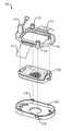
- FIG. 2Ais a schematic depicting the components of an exemplary embodiment of a blister harvesting device according to the invention
- FIG. 2Bis a schematic depicting the components of an exemplary embodiment of a blister generation module for coupling with the blister harvesting device of FIG. 2A .
- FIGS. 3A-3Care schematics depicting the assembly procedure of the components depicted in FIGS. 2A and 2B .
- FIG. 4is a schematic depicting the components of an exemplary embodiment of a cutter assembly for use in the devices according to the invention.
- FIG. 5Ais a schematic depicting an exemplary embodiment of a device according to the invention in a blister generation mode
- FIG. 5Bis a schematic depicting an exemplary embodiment of a device according to the invention in a blister harvesting mode.
- FIGS. 6A-6Fare schematics depicting the blister generation steps using the device mode depicted in FIG. 5A .
- FIGS. 7A-7Fare schematics depicting the blister harvesting steps using the device mode depicted in FIG. 5B .
- the skinconsists of 2 layers.
- the outer layer, or epidermisis derived from ectoderm, and the thicker inner layer, or dermis, is derived from mesoderm.
- the epidermisconstitutes about 5% of the skin, and the remaining 95% is dermis.
- FIG. 1provides a diagram showing the anatomy of skin. The skin varies in thickness depending on anatomic location, gender, and age of the individual.
- the epidermisthe more external of the two layers, is a stratified squamous epithelium consisting primarily of melanocytes and keratinocytes in progressive stages of differentiation from deeper to more superficial layers.
- the epidermishas no blood vessels; thus, it must receive nutrients by diffusion from the underlying dermis through the basement membrane, which separates the two layers.
- epidermal layerhas been demonstrated in the literature to have significant applications in a number of different indications, including wound-care and vitiligo.
- epidermal graftingis difficult to perform in practice due to the extreme thinness (100 microns) and wet consistency of the tissue, as well as concerns regarding donor-site morbidity.
- the dermisis a more complex structure. It is composed of 2 layers, the more superficial papillary dermis and the deeper reticular dermis.
- the papillary dermisis thinner, including loose connective tissue that contains capillaries, elastic fibers, reticular fibers, and some collagen.
- the reticular dermisincludes a thicker layer of dense connective tissue containing larger blood vessels, closely interlaced elastic fibers, and coarse, branching collagen fibers arranged in layers parallel to the surface.
- the reticular layeralso contains fibroblasts, mast cells, nerve endings, lymphatics, and some epidermal appendages.
- Surrounding the components of the dermisis the gel-like ground substance composed of mucopolysaccharides (primarily hyaluronic acid), chondroitin sulfates, and glycoproteins.
- the characteristics of the donor site that are more likely to be maintained after grafting to a recipient siteis a function of the thickness of the dermal component of the graft.
- thicker graftsrequire more favorable conditions for survival due to the requirement for increased revascularization.
- a substantially epidermal graft according to the inventionis more likely to adapt to the characteristics of the recipient site, presumably due to the presence of pluripotent stem cells in the epidermal layer.
- the inventionrelates to an integrated device for generating micrografts and transferring micrografts. More specifically, the invention relates to a device for generating substantially planar micrografts and for preparing a surgical dressing to facilitate presentation of the micrografts to a patient in need thereof.
- the device of the inventioncan be used to prepare any type of skin graft, such as an epidermal skin graft, a split thickness graft, or a full thickness graft.
- the device of the inventionis particularly well suited for preparing skin grafts including only or substantially only the epidermal layer of skin.
- the device of the inventioncan be used for autografts, allografts, or xenografts. In preferred embodiments, the grafts are autografts.
- device 200includes a top housing 201 , a cutter assembly 202 and a base housing 203 .
- the top housingincludes a rotatable handle 213 that is coupled to the cutter assembly 202 .
- the top housingfurther includes a strap 211 for coupling the device 200 (once assembled) against a skin surface.
- the strapmay be adjustable in size, or may be a fixed size.
- the top housing 201is configured to removably receive a blister generation module 210 that includes a blister generation device 204 and an adaptor plate 205 ( FIG. 2B ).
- FIGS. 3A-3Cdepict the assembly of device 200 .
- cutter assembly 202is inserted into top housing 201 .
- Top housing 201is then coupled to base housing 203 via one or more threaded screws 212 that are received by a corresponding threaded holes 218 in base housing 203 , such that cutter assembly 202 is disposed in between top housing 201 and bottom housing 203 ( FIG. 3B ).
- the blister generation module 210is then inserted into top housing 201 .
- the bottom of adaptor plate 205 that interfaces with top housing 201includes a gasket around the bottom perimeter of the plate 205 to create an airtight seal between adaptor plate 205 and top housing 201 when coupled together.
- the blister generation device 204 of the blister generation module 210is coupled to an opening 205 a within adaptor plate 205 .
- a gasketis disposed within opening 205 a to form an airtight seal between blister generation device 204 and adaptor plate 205 when coupled together.
- the cutter assembly 202includes a bottom plate 202 a , a middle plate 202 b , and a top plate 202 c , each of which include an array of openings 214 (e.g., holes or slots) (sometimes referred to herein as hole array 214 ).
- One or more openings of the hole array 214 in the bottom 202 a , middle 202 b and/or top 202 c platesdefine a cutting edge or surface 215 .
- one or more openings in the hole array 214 of at least the middle plate 202 bdefine a cutting edge or surface 215 ( FIG. 4 ).
- the three platesare assembled in a stacked configuration with the middle plate 202 b being coupled to the bottom plate 202 a , and the top plate 202 c being coupled to the middle plate 202 b .
- One or more of plates 202 a , 202 b and 202 care configured to be movable in a lateral direction relative to each other.
- the middle plate 202 bmay be laterally movable relative to the bottom plate 202 a , the top plate 202 c , or both.
- the top plate 202 cmay be movable relative to the middle plate 202 b , the bottom plate 202 a , or both.
- the one of more of plates 202 a , 202 b and 202 care configured to laterally move within a fixed distance relative to each other.
- the middle plate 202 b and/or top plate 202 ccan be coupled to their respective plates in the stacked configuration via at least one frangible section which serves to keep the plates in alignment until a lateral force is applied to the middle 202 b and/or top 202 c plate, which breaks the frangible section(s) and allows lateral movement of the plates relative to each other.
- at least the middle plate 202 bis coupled to the bottom plate 202 a via at least one frangible section.
- the at least one frangible sectionis configured to break when a lateral force is applied to the middle plate 202 b , allowing the middle plate 202 b to move in a lateral direction relative to the bottom plate 202 a , the top plate 202 c , or both.
- middle plate 202 bis configured to laterally move within a fixed distance relative to the bottom plate 202 a and/or top plate 202 c .
- the middle plate 202 bincludes one or more grooves or channels 216 that are configured to receive a pin 217 vertically extending from bottom plate 202 a .
- Pin 217is received at one end of channel 216 when the frangible section is intact, and laterally slides within channel 216 to the opposite end when the frangible section is broken, such that the lateral movement of plate 202 b relative to plate 202 a and/or 202 c is fixed by the movement of pin 217 within channel 216 .
- One or more coupling memberscan be disposed between the plates to form the frangible sections, as described in further detail below.
- the one or more coupling membersare disposed between the openings within hole array 214 .
- the one or more coupling membersare disposed between the plates outside of hole array 214 .
- the frangible coupling of the plate members to each othercan be accomplished using a mechanical stamping technique, a mechanical punch technique, spot welding, photo etching, an epoxy, an adhesive, mechanical compression, a snap-fit assembly, a tongue and groove assembly, a post and bar assembly, a frangible pin, or any combination thereof.
- the middle plate 202 b and/or top plate 202 ccan be coupled to their respective plates in the stacked configuration via at least one elastic member or spring member which serves to keep the plates in alignment until a lateral force is applied to the middle 202 b and/or top 202 c plate, which allows the elastic/spring section(s) to flex and allows lateral movement of the plates relative to each other. Upon removal of the lateral force, the elastic/spring sections relax, which allows the plates to return to their original positions such that the hole arrays 214 between the plates are once again in concentric alignment.
- the one or more elastic coupling members or spring memberscan be disposed between the openings within hole array 214 . Alternatively, the one or more elastic coupling members or spring members can be disposed between the plates outside of hole array 214 .
- the hole arrays 214 of the bottom 202 a , middle 202 b and top 202 c platesinclude holes that are substantially similar in size and substantially cylindrical in shape.
- the size of the holes in each hole array 214will depend on the size of the graft needed, with larger holes being used in each plate to produce larger grafts. In certain embodiments, the holes in the hole array 214 range between 1 mm and 12 mm in diameter, or any specific value in between.
- the diameter of the holes in the hole array 214 of one or more of plates 202 a , 202 b and 202 ccan be 1 mm, 1.5 mm, 2 mm, 2.5 mm, 3 mm, 3.5 mm, 4 mm, 4.5 mm, 5 mm, 5.5 mm, 6 mm, 6.5 mm, 7 mm, 7.5 mm, 8 mm, 8.5 mm, 9 mm, 9.5 mm, 10 mm, 10.5 mm, 11 mm, 11.5 mm or 12 mm.
- the holes in hole array 214vary in size and/or shape between the bottom plate 202 a , middle plate 202 b and/or top plate 202 c .
- the device 200has two modes of operation: 1) a blister generation mode ( FIG. 5A ); and 2) a blister harvesting mode ( FIG. 5B ).
- the blister generation modeincludes the assembly with the blister generation module 210 .
- the blister generation module 210is removed from the device assembly for blister harvesting mode ( FIG. 5B ).
- device 200 in the blister generation modei.e., with blister generation module 210 , as shown in FIG. 5A
- a donor site 220such as an inner thigh of a patient ( FIGS. 6A and 6B ).
- Strap 211is used to keep the device 200 in place against the skin surface of donor site 220 .
- the blister generation device 204is activated by turning/cranking handle 204 a of blister generation device 204 .
- the blister generation device 204utilizes a vacuum component, a heating component, or a combination thereof, for raising skin blisters.
- An exemplary heating componentis a light source.
- mechanismis a combination of a vacuum component and a heating component.
- the blister generation device 204is a suction blister device for suction blister grafting.
- Suction blister graftinginvolves raising a skin blister, and then cutting off the raised blister.
- An exemplary suction blister grafting techniqueis shown in Awad, (Dermatol Surg, 34(9):1186-1193, 2008), the content of which is incorporated by reference herein in its entirety.
- This articlealso shows various devices used to form suction blisters.
- a suction blister deviceis also described in Kennedy et al. (U.S. Pat. No. 6,071,247), the content of which is incorporated by reference herein in its entirety.
- An exemplary deviceis the commercially available Negative Pressure Cutaneous Suction System from Electronic Diversities (Finksburg, Md.).
- a device for raising a suction blistertypically operates by use of suction chambers that are attached to a patient's skin.
- An instrumenttypically contains a power source, a vacuum pump, temperature controls and all related controls to operate multiple suction chambers.
- the suction chambersare connected to the console by a flexible connection.
- Each of the chambersis controlled by a preset temperature control to provide an optimal skin warming temperature. Both chambers share an adjustable common vacuum source that affects all chambers equally.
- the chamber heating systemprovides a slight warming of an orifice plate of the device, which is in direct contact with the patient's skin surface.
- the negative pressure chamberis fabricated of mostly plastic components, with two removable threaded caps. The upper cap is fitted with a clear viewing lens so that the actual blister formation can be observed.
- the opposite end of the chamberis fitted with a removable orifice plate that is placed on the patient's skin. Since this plate is simply threaded onto the chamber end, multiple plates with different opening patterns can be interchanged as desired.
- the interior of the deviceis warmed and illuminated by an array of low voltage incandescent lamps.
- This lamp arrayis controlled from the instrument console temperature controller, cycling as needed, to maintain the set point temperature.
- the heat from these lampsis radiated and conducted to the orifice plate, which then warms the patient's skin.
- the chamberis connected to the console via a composite vacuum and low voltage electrical system. Quick connections are used for the vacuum and electrical system to facilitate removal and storage.
- the Negative Pressure Instrument consoleis a self-contained fan cooled unit which is designed to operate on 120 VAC 60 Hz power. Vacuum is supplied by an industrial quality diaphragm type vacuum pump, capable of a typical vacuum of 20 in Hg (0-65 kpa) at 0 CFM. An analog controller that is preset to 40° C. provides the temperature control for each suction chamber. This provides accurate control of the orifice plate temperature.
- the instrument consolehas internal adjustments that allow the user to recalibrate the temperature setting if desired. Other temperatures can be preset if desired.
- the front panelincludes a vacuum gauge and vacuum bleeder adjustment to regulate the vacuum to both chambers. The console front panel also contains the connections for the chamber assemblies.
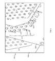
- the application of a moderate negative pressure from the blister generation device 204causes the patients skin to be gently drawn through the concentrically aligned hole arrays 214 of plates 202 a , 202 b and 202 c in cutter assembly 202 ( FIGS. 6C and 6D ).
- Such actionresults in generation of a plurality of raised microblisters 221 , particularly epidermal microblisters.
- the blisters 221may or may not be fluid-filled.
- the plurality of suction blisters 221 generatedare of uniform size, approximately the size of the openings/holes in the hole arrays 214 of the three plates of cutter assembly 202 , and are uniformly spaced in accordance with the configuration of the holes in hole array 214 , such that a plurality of substantially planar microblisters 221 are generated.
- the skin and blister areais generally not damaged and patient discomfort is minimal.
- the deviceis converted into the blister harvesting mode by removing the blister generation module 210 from the top housing 201 , thereby exposing the hole array 214 in the top plate 202 c of cutter assembly 202 . At least a portion of the raised microblisters 221 protrude through the top of the hole array 214 , as shown in FIGS. 6B and 6C .
- a substrate 219is applied to the surface of hole array 214 , as shown in FIGS. 5B and 7A , such that the substrate 219 is in direct contact with the raised blisters 221 .
- handle 213is rotated in a clockwise or counterclockwise direction ( FIG. 7C ).
- Handle 213is coupled to the middle plate 202 b of cutter assembly 202 in a configuration that translates the rotational movement of the handle 213 into lateral movement of middle plate 202 b .
- the lateral force applied to middle plate 202 b by handle 213causes middle plate 202 b to move in a lateral direction relative to bottom plate 202 a and/or top plate 202 c , thereby disrupting the alignment of the hole arrays 214 between plates 202 a , 202 b and 202 c .
- the lateral displacement of the hole array 214 of middle plate 202 bcauses the cutting surface 215 defined by one or more holes in the hole array 214 to cut the raised blisters 221 .
- the raised blisters 221are simultaneously transferred/retained on substrate 219 in the same configuration as generated within hole array 214 , resulting in a substrate containing a plurality of micrografts that are uniformly spaced and oriented on the substrate 219 (i.e., a substrate containing a plurality of substantially planar micrografts).
- device 200integrate consumable/single-use components (e.g., substrate 219 and/or cutter assembly 202 ) and re-usable, sterilizable or cleaned components (e.g., top housing 201 , base housing 203 and blister generation module 210 ), thereby providing a reliable system that is easy to maintain. All components of device 200 that come into contact with the donor and/or recipient tissue (both single-use and reusable components) must be sterile/sterilized to reduce the risk of infection.
- consumable/single-use componentse.g., substrate 219 and/or cutter assembly 202
- re-usable, sterilizable or cleaned componentse.g., top housing 201 , base housing 203 and blister generation module 210
- substrate 219includes an adhesive on one side that facilitates attachment of the blisters to the substrate.
- the substrate materialmay have intrinsic adhesive properties, or alternatively, a side of the substrate may be treated with an adhesive material, e.g., an adhesive spray such as LEUKOSPRAY (Beiersdoerf GmbH, Germany).
- the substratemay be a deformable non-resilient material.
- a deformable non-resilient materialrefers to a material that may be manipulated, e.g., stretched or expanded, from a first configuration to a second configuration, and once in the second configuration, there is no residual stress on the substrate. Such materials may be stretched to an expanded configuration without returning to their original size.
- Such deformable non-resilient materialstend to be soft, stiff or both soft and stiff. Softness is measured on the durometer scale.
- An example of such a materialis a soft polyurethane.
- a soft polyurethaneis produced is as follows. Polyurethanes in general usually have soft and hard segments. The hard segments are due to the presence of phenyl bridges. In a soft polyurethane, the phenyl bridge is switched out for an aliphatic, which is more flexible as its 6 carbon ring has no double bonds. Therefore, all the segments are soft. On the Durometer Scale, a soft polyethylene is rated about Shore 80A.
- the substrate 219is TegadermTM, which is a transparent medical dressing manufactured by 3M Company, U.S.A.
- the substrate containing the plurality of uniformly spaced and oriented (i.e., substantially planar) micrograftsis applied to a recipient of site of a patient.
- the sitePrior to applying the grafts to the recipient site, the site is prepared to receive the grafts using any technique known in the art. Necrotic, fibrotic or avascular tissue should be removed. The technique used to prepare the site will depend on damage to the recipient site. For example, epidermal tissue, if present at the recipient site, can be removed to prepare the area for receiving the micrografts. Burned or ulcerated sites may not need removal of epidermal tissue, although some cleaning of the site or other preparation of the site may be performed.
- Woundsshould be debrided and then allowed to granulate for several days prior to applying the graft. Most of the granulation tissue should be removed since it has a tendency to harbor bacteria. Applying silver sulfadiazine to the wound for 10 days prior to grafting reduces the bacterial count greatly.
- the size of the area at the recipient sitecan be about the same size as the area of the substrate having micrografts adhered thereto. This size generally will be greater than the area of the original graft tissue that was removed from the donor site to form the micrografts.
- the depigmented or damaged skincan be dermabraded with sandpaper or another rough material.
- the epidermal tissuecan be removed from the recipient site by forming one or more blisters over the area to be treated, e.g., a suction blister or a freezing blister, and the raised epidermal blister tissue can then be removed by cutting or another procedure.
- the substrate having the substantially planar micrograftscan be placed over the area to be treated to form a dressing.
- a portion of the substrate having the micrograftscan be positioned over the area to be repaired, e.g., the area from which the epidermal tissue has been abraded or removed for repigmentation.
- the substratecan be fixed in place over the treatment area, e.g., using tape or the like.
- the substratecan be removed after sufficient time has elapsed to allow attachment and growth of the micrografts in the treatment area, e.g., several days to a few weeks.
- the inventionfurther relates to methods for manufacturing uniform components for use in the integrated devices of the invention.
- the components within cutter assembly 202must be substantially uniform with respect to one another.
- the planar surfaces of the components within cutter assembly 202must be substantially uniform.
- one or more coupling membersare used to create a frangible coupling between at least two of plate members 202 a , 202 b and 202 c .
- the coupling membersare disposed between two or more of the plate members to form a frangible section that is broken upon movement of said plates with respect to each other, as previously described.
- the tolerance for any inconsistencies between the planar surfaces of the coupling members and one or more of the plate members and/or inconsistent dimensions (e.g., width) between the coupling members and one or more of the plate membersis very low and could result in non-planar, non-uniform micrografts and device malfunction.
- Inconsistencies between the planar surfaces of different stocks of sheet material, manufacturing methods of blanks for the coupling members and/or plates, and finishing methods of the coupling members and/or platescan each increase tolerance stackups beyond an acceptable level, thereby decreasing the efficiency and function of device and resulting in micrografts that are unusable, and increase patient discomfort/distress.
- the plurality of coupling membersare preferably formed from the same sheet stock of material as at least one plate member in the cutter assembly 202 .
- the plurality of coupling members and at least middle plate member 202 b in cutter assembly 202are preferably formed from the same sheet stock of material (e.g., a single sheet stock of material).
- Forming the coupling members and the middle plate member 202 b from the same sheet stockensures a uniform thickness between the coupling members and between the coupling members and plate member 202 b , and ensures uniform, planar mating surfaces between the coupling members and plate member 202 b , thereby decreasing tolerance stackups within cutter assembly 202 and ensuring proper device function.
- Plate members 202 a , 202 b , and 202 ccan be formed from the same material, or different materials with respect to each other, so long as the materials used result in substantially planar mating surfaces between the three plates.
- plate members 202 a , 202 b , and 202 care formed from a metallic material (e.g., the same metallic material, or different metallic materials).
- each of plate member 202 a , 202 b , and 202 cis formed from the same sheet stock of material, preferably a single sheet stock of material.
- One or more openingsare formed within each plate member to form hole arrays 214 that align when the plate members are assembled, as previously described.
- the coupling membersare formed from the same sheet stock from which the plurality of plate members are generated. Forming the coupling members and plate members from the same sheet stock ensures uniformity in the thickness among and between the coupling members and plate members, and uniformly planar mating surfaces between the coupling members and plate members, thereby decreasing tolerance stackups within cutter assembly 202 and ensuring proper device function.
- the coupling memberscan be any shape or dimension sufficient to couple the plates together without obstructing the holes in the hole arrays 214 through which the suction blisters are raised.
- the coupling memberscan be substantially square or rectangular in shape.
- the coupling membersare substantially circular in shape.
- the coupling membersare of a sufficient shape and size for location between the holes of the hole arrays 214 of the plate members.
- the coupling membersare of a sufficient shape and size for location along the edges of the plurality of plates.
- any methodcan be used to manufacture the plates and/or coupling members, such as drilling, milling, laser etching, lithographic processing, photo etching, laser ablation and the like.
- a photo etching processis used to manufacture the plates and/or coupling members.
- the frangible coupling between the coupling members and plate memberscan be accomplished using a variety of techniques.
- the coupling memberscan be frangibly coupled between the plate members via spot welding techniques (e.g., laser spot welding), via an adhesive such as epoxy, polyurethane, acrylic or a resin, via a frangible pin, a snap-fit or tongue and groove assembly.
- frangible coupling techniquescan be accomplished using one or more manufacturing processes such as cold-heading, multiple-die forming, multiple-die progression, multiple-die headers, casting, stamping, punching, atomic hydrogen welding, bare metal arc welding, carbon arc welding, flux cored arc welding, gas metal arc welding, gas tungsten arc welding, plasma arc welding, shielded metal arc welding, submerged arc welding, air acetylene welding, oxyacetylene welding, oxygen/propane welding, oxy hydrogen welding, pressure gas welding, resistance spot welding, resistance seam welding, projection welding, flash welding, upset welding, co-extrusion welding, cold pressure welding, diffusion welding, explosion welding, electromagnetic pulse welding, forge welding, friction welding, friction stir welding, hot pressure welding, hot isostatic pressure welding, roll welding, ultrasonic welding, electron beam welding, electroslag welding, flow welding, induction welding, laser beam welding, percussion welding, thermite welding, electrogas welding, and stud arc welding.
- manufacturing processessuch as cold-head
- a portion of the plate material at or around the site of the frangible couplingis removed to accommodate at least a portion of the coupling member by forming a depression at or around the frangible section.
- laser etching or photo etching on the plate memberis used to circumscribe the coupling point at or proximal to the frangible coupling.
- a depression at or proximal to the plate membercan be removed with any method known in the art, for example drilling, milling, laser etching, photo etching, laser ablation and the like.
- the devices of the inventioncan be used to prepare a skin graft to repair numerous different types of skin damage.
- the devices of the inventionmay be used to prepare grafts to treat burns (e.g., both thermal and chemical burns), blistering, dermatological conditions (e.g., epidermolysis bullosa or pyoderma gangrenosum), radiation therapy ulcers, diabetic ulcers, ischemic ulcers, trophic ulcers, trauma, or depigmentation (e.g., vitiligo).
- devices 200 of the inventionare used to prepare a skin graft(s) for treating vitiligo.
- Vitiligois a chronic disorder that causes depigmentation of patches of skin. It occurs when melanocytes, the cells responsible for skin pigmentation, die or are unable to function. Although patches are initially small, they often enlarge and change shape. When skin lesions occur, they are most prominent on the face, hands and wrists. Some lesions have hyper-pigmentation around the edges. Depigmentation is particularly noticeable around body orifices, such as the mouth, eyes, nostrils, genitalia and umbilicus.
- Vitiligois generally classified into two categories, non-segmental vitiligo and Segmental vitiligo.
- non-segmental vitiligoNSV
- Vitiligo where little pigmented skin remainsis referred to as vitiligo universalis.
- Non-segmental vitiligocan come about at any age, unlike segmental vitiligo which is far more prevalent in teenage years.
- Segmental vitiligodiffers in appearance, aetiology and prevalence from associated illnesses. Its treatment is different from that of non-segmental vitiligo. It tends to affect areas of skin that are associated with dorsal roots from the spine. It spreads much more rapidly than non-segmental vitiligo and, without treatment, it is much more stable/static in course and not associated with auto-immune diseases.
Landscapes
- Health & Medical Sciences (AREA)
- Surgery (AREA)
- Life Sciences & Earth Sciences (AREA)
- Molecular Biology (AREA)
- General Health & Medical Sciences (AREA)
- Veterinary Medicine (AREA)
- Engineering & Computer Science (AREA)
- Biomedical Technology (AREA)
- Heart & Thoracic Surgery (AREA)
- Medical Informatics (AREA)
- Public Health (AREA)
- Animal Behavior & Ethology (AREA)
- Nuclear Medicine, Radiotherapy & Molecular Imaging (AREA)
- Plastic & Reconstructive Surgery (AREA)
- Transplantation (AREA)
- Oral & Maxillofacial Surgery (AREA)
- Pathology (AREA)
- Surgical Instruments (AREA)
- Media Introduction/Drainage Providing Device (AREA)
- Treatment Of Fiber Materials (AREA)
- Materials For Medical Uses (AREA)
Abstract
Description
Claims (16)
Priority Applications (12)
| Application Number | Priority Date | Filing Date | Title |
|---|---|---|---|
| US13/346,329US8978234B2 (en) | 2011-12-07 | 2012-01-09 | Methods of manufacturing devices for generating skin grafts |
| PCT/US2012/068551WO2013086400A1 (en) | 2011-12-07 | 2012-12-07 | Methods of manufacturing devices for generating skin grafts |
| EP18174326.1AEP3420981B1 (en) | 2011-12-07 | 2012-12-07 | Devices for generating skin grafts |
| BR112014013363-8ABR112014013363B1 (en) | 2011-12-07 | 2012-12-07 | method of fabricating a plurality of plates for use in one device to obtain a skin graft |
| EP12855127.2AEP2787905B1 (en) | 2011-12-07 | 2012-12-07 | Methods of manufacturing devices for generating skin grafts |
| CA2857995ACA2857995C (en) | 2011-12-07 | 2012-12-07 | Methods of manufacturing devices for generating skin grafts |
| AU2012347592AAU2012347592A1 (en) | 2011-12-07 | 2012-12-07 | Methods of manufacturing devices for generating skin grafts |
| US13/839,518US9610093B2 (en) | 2010-08-06 | 2013-03-15 | Microblister skin grafting |
| US14/657,964US9848908B2 (en) | 2011-12-07 | 2015-03-13 | Devices for generating skin grafts |
| US15/439,289US10537355B2 (en) | 2010-08-06 | 2017-02-22 | Microblister skin grafting |
| AU2017279616AAU2017279616B2 (en) | 2011-12-07 | 2017-12-19 | Methods of manufacturing devices for generating skin grafts |
| US16/748,756US20200155187A1 (en) | 2010-08-06 | 2020-01-21 | Microblister skin grafting |
Applications Claiming Priority (2)
| Application Number | Priority Date | Filing Date | Title |
|---|---|---|---|
| US201161567946P | 2011-12-07 | 2011-12-07 | |
| US13/346,329US8978234B2 (en) | 2011-12-07 | 2012-01-09 | Methods of manufacturing devices for generating skin grafts |
Related Parent Applications (2)
| Application Number | Title | Priority Date | Filing Date |
|---|---|---|---|
| US13/346,318Continuation-In-PartUS9173674B2 (en) | 2010-08-06 | 2012-01-09 | Devices for harvesting a skin graft |
| US13436318Continuation-In-Part | 2012-03-30 |
Related Child Applications (2)
| Application Number | Title | Priority Date | Filing Date |
|---|---|---|---|
| US13/839,518Continuation-In-PartUS9610093B2 (en) | 2010-08-06 | 2013-03-15 | Microblister skin grafting |
| US14/657,964ContinuationUS9848908B2 (en) | 2011-12-07 | 2015-03-13 | Devices for generating skin grafts |
Publications (2)
| Publication Number | Publication Date |
|---|---|
| US20130145596A1 US20130145596A1 (en) | 2013-06-13 |
| US8978234B2true US8978234B2 (en) | 2015-03-17 |
Family
ID=48570702
Family Applications (2)
| Application Number | Title | Priority Date | Filing Date |
|---|---|---|---|
| US13/346,329Active2032-05-12US8978234B2 (en) | 2010-08-06 | 2012-01-09 | Methods of manufacturing devices for generating skin grafts |
| US14/657,964ActiveUS9848908B2 (en) | 2011-12-07 | 2015-03-13 | Devices for generating skin grafts |
Family Applications After (1)
| Application Number | Title | Priority Date | Filing Date |
|---|---|---|---|
| US14/657,964ActiveUS9848908B2 (en) | 2011-12-07 | 2015-03-13 | Devices for generating skin grafts |
Country Status (6)
| Country | Link |
|---|---|
| US (2) | US8978234B2 (en) |
| EP (2) | EP3420981B1 (en) |
| AU (2) | AU2012347592A1 (en) |
| BR (1) | BR112014013363B1 (en) |
| CA (1) | CA2857995C (en) |
| WO (1) | WO2013086400A1 (en) |
Cited By (6)
| Publication number | Priority date | Publication date | Assignee | Title |
|---|---|---|---|---|
| WO2017143229A1 (en) | 2016-02-19 | 2017-08-24 | Kci Licensing, Inc. | Transfected epidermal grafts and methods of making the same |
| USD796671S1 (en)* | 2016-01-21 | 2017-09-05 | Roger Khouri | Tissue mesher |
| WO2018102342A1 (en) | 2016-11-29 | 2018-06-07 | Kci Licensing, Inc. | Identification and visualization of micrografts for monitoring epithelialization |
| US10278724B2 (en) | 2008-09-24 | 2019-05-07 | The General Hospital Corporation | Method and apparatus for grafting of skin tissue |
| US11006974B2 (en) | 2015-11-03 | 2021-05-18 | Kci Licensing, Inc. | Devices for creating an epidermal graft sheet |
| US12133662B2 (en) | 2020-08-19 | 2024-11-05 | Timothy Chen | Skin graft harvester |
Families Citing this family (14)
| Publication number | Priority date | Publication date | Assignee | Title |
|---|---|---|---|---|
| US9173674B2 (en) | 2010-08-06 | 2015-11-03 | MoMelan Technologies, Inc. | Devices for harvesting a skin graft |
| US8978234B2 (en) | 2011-12-07 | 2015-03-17 | MoMelan Technologies, Inc. | Methods of manufacturing devices for generating skin grafts |
| US9610093B2 (en) | 2010-08-06 | 2017-04-04 | Kci Licensing, Inc. | Microblister skin grafting |
| US9597111B2 (en) | 2010-08-06 | 2017-03-21 | Kci Licensing, Inc. | Methods for applying a skin graft |
| EP3289988A1 (en) | 2013-03-14 | 2018-03-07 | KCI Licensing, Inc. | Absorbent substrates for harvesting skin grafts |
| US9814485B2 (en) | 2013-12-31 | 2017-11-14 | Kci Licensing, Inc. | Hydraulically actuated skin graft harvesting |
| US10463392B2 (en) | 2013-12-31 | 2019-11-05 | Kci Licensing, Inc. | Fluid-assisted skin graft harvesting |
| WO2015103043A1 (en)* | 2013-12-31 | 2015-07-09 | Kci Licensing, Inc. | Sensor systems for skin graft harvesting |
| US10912861B2 (en) | 2015-04-09 | 2021-02-09 | Kci Licensing, Inc. | Soft-tack, porous substrates for harvesting skin grafts |
| RU2614100C1 (en)* | 2016-02-04 | 2017-03-22 | Федеральное государственное бюджетное образовательное учреждение высшего образования "Кубанский государственный медицинский университет" Министерства здравоохранения Российской Федерации (ФГБОУ ВО КубГМУ Минздрава России) | Method for hand skin plastics |
| RU2618166C1 (en)* | 2016-02-05 | 2017-05-02 | Государственное Бюджетное Образовательное Учреждение Высшего Профессионального Образования "Кубанский государственный медицинский университет" Министерства здравоохранения Российской Федерации (ГБОУ ВПО КубГМУ Минздрава России) | Method of cutting out skin autotransplant |
| RU2622979C1 (en)* | 2016-02-05 | 2017-06-21 | Сергей Борисович Богданов | Method for surgical treatment of deep skin defects |
| DE102017106310B4 (en) | 2017-03-23 | 2018-10-11 | Lavenir Bioscience Ag | Apparatus and method for producing a micrograft matrix from full skin |
| US20220183712A1 (en)* | 2020-12-11 | 2022-06-16 | 3D Systems, Inc. | Carrier Matrix for Facilitating Transfer of Skin Cores from Donor Site to Wound Site |
Citations (87)
| Publication number | Priority date | Publication date | Assignee | Title |
|---|---|---|---|---|
| US2379574A (en) | 1943-11-05 | 1945-07-03 | Claude R Wickard | Method of producing surgical bandages with improved elastic properties |
| US3054404A (en) | 1961-08-14 | 1962-09-18 | Cicero P Meek | Skin graft applicator |
| US3782387A (en) | 1972-02-29 | 1974-01-01 | R Falabella | Apparatus and methods for obtaining and making skin grafts |
| US4345374A (en)* | 1974-01-14 | 1982-08-24 | The Gillette Company | Razor with means to adjust blade geometry |
| US4666447A (en) | 1985-01-30 | 1987-05-19 | Mentor Corporation | Skin expansion device and method of making the same |
| US4679324A (en)* | 1984-11-15 | 1987-07-14 | The Gillette Company | Safety razor blades |
| US4773418A (en)* | 1982-12-22 | 1988-09-27 | Rolf Hettich | Method for manufacturing a transplant |
| US4917086A (en)* | 1988-05-26 | 1990-04-17 | Snyder Laboratories, Inc. | Dermatome blade assembly |
| US5015584A (en) | 1987-10-14 | 1991-05-14 | Board Of Regents, The University Of Texas System | Epidermal graft system |
| WO1992011879A1 (en) | 1991-01-09 | 1992-07-23 | Principal Ab | Transdermal perfusion of fluids |
| US5386633A (en)* | 1993-12-27 | 1995-02-07 | Kanno; Yukio | Hamburger patty knife with blade attachment |
| US5460939A (en) | 1986-04-18 | 1995-10-24 | Advanced Tissue Sciences, Inc. | Temporary living skin replacement |
| WO1995028886A1 (en) | 1994-04-21 | 1995-11-02 | Medchem Products, Inc. | Skin stretching device |
| US5476478A (en) | 1994-04-18 | 1995-12-19 | Providence Hospital | Preoperative skin stretching apparatus and method |
| US5489304A (en) | 1994-04-19 | 1996-02-06 | Brigham & Women's Hospital | Method of skin regeneration using a collagen-glycosaminoglycan matrix and cultured epithelial autograft |
| US5496339A (en)* | 1994-05-17 | 1996-03-05 | Koepnick; Russell G. | Universal automated keratectomy apparatus and method |
| WO1996018432A1 (en) | 1994-12-16 | 1996-06-20 | Gelbfish Gary A | Method and associated device for removing material from body |
| US5545222A (en) | 1991-08-12 | 1996-08-13 | Bonutti; Peter M. | Method using human tissue |
| WO1996033768A2 (en) | 1995-04-27 | 1996-10-31 | Svedman Paul | Suction blister sampling |
| US5571098A (en) | 1994-11-01 | 1996-11-05 | The General Hospital Corporation | Laser surgical devices |
| US5595570A (en)* | 1994-12-06 | 1997-01-21 | S.C.M.D., Ltd. | Keratome with spring loaded adjustable plate, cutting length adjustment plate, method of cutting a corneal flap, and gauge-mounted bracket for adjusting plate on keratome head |
| WO1997020509A2 (en) | 1995-12-07 | 1997-06-12 | L.R. Surgical Instruments Ltd. | An adjustable skin mesher device and a system for using the same |
| US5686303A (en) | 1994-12-30 | 1997-11-11 | Korman; Joshua | Method of growing vertebrate skin in vitro |
| WO1998016158A1 (en) | 1996-10-15 | 1998-04-23 | Burncare Bv | Method and instruments for forming skin grafts |
| US5817115A (en)* | 1995-12-04 | 1998-10-06 | Chiron Vision Corporation | Apparatus for resecting corneal tissue |
| US5914261A (en) | 1990-06-01 | 1999-06-22 | Regeneron Pharmaceuticals, Inc. | Family of MAP2 protein kinases |
| US5921980A (en) | 1997-12-03 | 1999-07-13 | University Of Kentucky Research Foundation | Laser skin graft harvesting apparatus and related method |
| US5972476A (en)* | 1997-11-21 | 1999-10-26 | Means Industries, Inc. | Laminated parts and method of making same |
| US6056738A (en) | 1997-01-31 | 2000-05-02 | Transmedica International, Inc. | Interstitial fluid monitoring |
| US6071247A (en) | 1996-07-21 | 2000-06-06 | Kennedy; William R. | Skin blister biopsy apparatus and method |
| US6080166A (en)* | 1995-12-05 | 2000-06-27 | Mcewen; James Allen | Direct linear drive dermatome |
| US6358260B1 (en) | 1998-04-20 | 2002-03-19 | Med-Logics, Inc. | Automatic corneal shaper with two separate drive mechanisms |
| US20020052614A1 (en)* | 2000-10-16 | 2002-05-02 | Gebauer Detlev P. | Blade with amorphous cutting edge |
| US6402770B1 (en) | 1998-06-01 | 2002-06-11 | Avatar Design & Development, Inc. | Method and apparatus for placing and maintaining a percutaneous tube into a body cavity |
| US6436078B1 (en) | 1994-12-06 | 2002-08-20 | Pal Svedman | Transdermal perfusion of fluids |
| WO2003020333A2 (en) | 2001-08-29 | 2003-03-13 | Artemis Medical, Inc. | Undamaged tissue collection assembly and method |
| WO2003039382A2 (en) | 2001-11-05 | 2003-05-15 | Medgenics, Inc. | System for processing tissue |
| US6585939B1 (en)* | 1999-02-26 | 2003-07-01 | Orchid Biosciences, Inc. | Microstructures for use in biological assays and reactions |
| US6623498B1 (en) | 1999-02-10 | 2003-09-23 | Sis Ltd. | Cutting instrument |
| US20040097967A1 (en) | 2000-10-27 | 2004-05-20 | Ignon Roger G. | Method for skin/surface abrasion |
| WO2004071313A2 (en) | 2003-02-10 | 2004-08-26 | Applied Tissue Technologies, Llc | Apparatus for dermal tissue harvesting |
| US20040172045A1 (en) | 2002-09-28 | 2004-09-02 | Elof Eriksson | System and method for transplantation of dermal tissue |
| WO2004075764A1 (en) | 2003-02-27 | 2004-09-10 | Applied Tissue Technologies Llc | Method and apparatus for processing dermal tissue |
| WO2004078032A2 (en) | 2003-03-03 | 2004-09-16 | Kci Licensing, Inc. | Tissue processing system |
| US20040186498A1 (en)* | 2003-03-17 | 2004-09-23 | Barnes Stephen Matthew | Microkeratome blade with blade separation notch |
| US6800282B1 (en) | 1997-06-26 | 2004-10-05 | Smith & Nephew, Plc | Cell culture products |
| US20040215217A1 (en) | 2001-10-01 | 2004-10-28 | The Cleveland Clinic Foundation | Skin lesion exciser and skin-closure device therefor |
| US20040237744A1 (en) | 2003-06-02 | 2004-12-02 | Chien-Fu Lin | Photo cutting apparatus |
| WO2004105576A2 (en) | 2003-05-21 | 2004-12-09 | Kci Licensing, Inc. | Tissue harvesting device and method |
| US20050038520A1 (en) | 2003-08-11 | 2005-02-17 | Francois Binette | Method and apparatus for resurfacing an articular surface |
| US6860904B2 (en) | 1991-08-12 | 2005-03-01 | Bonutti 2003 Trust-A | Method for tissue grafting |
| US20050101972A1 (en) | 2003-11-06 | 2005-05-12 | University Of Florida Research Foundation, Inc. | Devices and systems for separating and preparing skin |
| US20050221276A1 (en)* | 2002-10-11 | 2005-10-06 | Case Western Reserve University | Sensor system |
| US20050234485A1 (en) | 2001-02-16 | 2005-10-20 | Charles Seegert | Skin grafting devices and methods |
| US7056327B2 (en)* | 1997-10-24 | 2006-06-06 | Becton, Dickinson & Company | Keratome with suspended stabilized blade, applanator and guided engagement with keratome cutter head |
| US20060141616A1 (en) | 2004-12-28 | 2006-06-29 | Yeou-Bin Guu | Cell colonies dissecting and transplanting apparatus |
| US7078582B2 (en) | 2001-01-17 | 2006-07-18 | 3M Innovative Properties Company | Stretch removable adhesive articles and methods |
| US7137979B2 (en) | 2003-05-31 | 2006-11-21 | Tyrell, Inc. | Methods and devices for the treatment of skin lesions |
| US20060271070A1 (en) | 2003-02-27 | 2006-11-30 | Elof Eriksson | Method and apparatus for processing dermal tissue |
| US7208006B2 (en) | 2002-03-01 | 2007-04-24 | Wilhelm Fleischmann | Process and instrument for stretching tissue of skin |
| US7207998B2 (en)* | 1998-08-12 | 2007-04-24 | Biovision Ag | Intracorneal lens placement method and apparatus |
| US7244444B2 (en) | 2004-03-31 | 2007-07-17 | Cook Incorporated | Graft material, stent graft and method |
| US20090085286A1 (en)* | 2007-09-26 | 2009-04-02 | T.E. Brangs, Inc. | Mechanical ball projection game devices |
| US7540875B2 (en) | 1998-06-01 | 2009-06-02 | Avatar Design & Development, Inc. | Surgical cutting tool with automatically retractable blade assembly |
| US20100012311A1 (en) | 2006-07-18 | 2010-01-21 | Airbus France | Heat flow device |
| WO2010036788A2 (en) | 2008-09-24 | 2010-04-01 | The General Hospital Corporation | Method and apparatus for grafting of skin tissue |
| US20100152750A1 (en) | 2006-09-14 | 2010-06-17 | Omeed Memar | Apparatus and Methods for Repairing Tissue Defects |
| US20100152651A1 (en)* | 2008-10-31 | 2010-06-17 | Searete Llc, A Limited Liability Corporation Of The State Of Delaware | Frozen compositions and methods for piercing a substrate |
| US20100310823A1 (en)* | 2007-10-03 | 2010-12-09 | Acell Group Limited | Composite products |
| WO2011038326A1 (en) | 2009-09-28 | 2011-03-31 | Wright Medical Technology, Inc. | Device for processing dermal tissue |
| WO2011059441A1 (en) | 2009-11-13 | 2011-05-19 | Smith & Nephew, Inc. | Mesher |
| WO2011075676A2 (en) | 2009-12-18 | 2011-06-23 | Knowlton Edward W | A skin treatment and drug delivery device |
| US8002779B2 (en)* | 2007-12-13 | 2011-08-23 | Zimmer Surgical, Inc. | Dermatome blade assembly |
| US20110251602A1 (en) | 2008-04-01 | 2011-10-13 | The General Hospital Corporation | Method and apparatus for tissue expansion |
| US20120021186A1 (en)* | 2010-06-07 | 2012-01-26 | Uwe Schneider | Seam structure and method for making a seam |
| WO2012019094A2 (en) | 2010-08-06 | 2012-02-09 | MoMelan Technologies, Inc. | Methods for preparing a skin graft |
| WO2012019098A1 (en) | 2010-08-06 | 2012-02-09 | MoMelan Technologies, Inc. | Methods for preparing a skin graft without culturing or use of biologics |
| WO2012019095A2 (en) | 2010-08-06 | 2012-02-09 | MoMelan Technologies, Inc. | Devices for harvesting a skin graft |
| WO2012019096A1 (en) | 2010-08-06 | 2012-02-09 | MoMelan Technologies, Inc. | Methods for applying a skin graft |
| US20120041430A1 (en) | 2008-04-01 | 2012-02-16 | The General Hospital Corporation | Method and apparatus for tissue grafting |
| US20120125798A1 (en) | 2009-05-30 | 2012-05-24 | Bayer Innovation Gmbh | Product having bioresorbable carrier materials and packaging |
| US20120172894A1 (en) | 2010-08-06 | 2012-07-05 | MoMelan Technologies, Inc. | Devices for harvesting a skin graft |
| US20120197267A1 (en) | 2011-01-27 | 2012-08-02 | MoMelan Technologies, Inc. | Devices for generating and transferring micrografts and methods of use thereof |
| US20120201793A1 (en) | 2001-11-05 | 2012-08-09 | Bellomo Stephen F | Dermal micro-organs, methods and apparatuses for producing and using the same |
| US20120244623A1 (en)* | 2008-08-20 | 2012-09-27 | Patel Gordhanbhai N | Tamper evident indicating devices |
| US20120271320A1 (en) | 2011-04-20 | 2012-10-25 | Kci Licensing, Inc. | Skin graft devices and methods |
| US20130041385A1 (en) | 2011-08-10 | 2013-02-14 | Joseph Giovannoli | Apparatus for skin reduction |
Family Cites Families (54)
| Publication number | Priority date | Publication date | Assignee | Title |
|---|---|---|---|---|
| US2579039A (en) | 1943-05-17 | 1951-12-18 | Us Electrical Motors Inc | Lubricating system |
| US2721555A (en) | 1952-12-03 | 1955-10-25 | John A Jenney | Dermatome |
| SU772544A1 (en) | 1979-01-04 | 1980-10-23 | Тартусский Ордена Трудового Красного Знамени Государственный Университет | Dermatome |
| DE3371743D1 (en) | 1982-07-21 | 1987-07-02 | Smith & Nephew Ass | Adhesive wound dressing |
| US4605010A (en)* | 1984-05-17 | 1986-08-12 | Western Clinical Engineering Ltd. | Pressurizing cuff |
| US4600533A (en) | 1984-12-24 | 1986-07-15 | Collagen Corporation | Collagen membranes for medical use |
| US5163955A (en) | 1991-01-24 | 1992-11-17 | Autogenics | Rapid assembly, concentric mating stent, tissue heart valve with enhanced clamping and tissue alignment |
| CN2125374U (en) | 1992-06-12 | 1992-12-23 | 王诚 | Negative pressure type skin auto-grafting apparatus |
| US5624451A (en)* | 1993-10-18 | 1997-04-29 | American Safety Razor | Flexible blade for removing skin lesions |
| US5433221A (en) | 1994-10-05 | 1995-07-18 | Adair; Edwin L. | Windowed self-centering drape for surgical camera |
| US20030152909A1 (en) | 1994-11-16 | 2003-08-14 | Mitrani Eduardo N. | In vitro micro-organs, and uses related thereto |
| US6693077B1 (en) | 1995-02-14 | 2004-02-17 | Human Genome Sciences, Inc. | Keratinocyte growth factor-2 |
| US6626901B1 (en) | 1997-03-05 | 2003-09-30 | The Trustees Of Columbia University In The City Of New York | Electrothermal instrument for sealing and joining or cutting tissue |
| US6080188A (en) | 1997-06-16 | 2000-06-27 | Medtronic, Inc. | Setscrew less lead connector system for medical devices |
| US6071267A (en) | 1998-02-06 | 2000-06-06 | Kinetic Concepts, Inc. | Medical patient fluid management interface system and method |
| US6083236A (en)* | 1998-08-12 | 2000-07-04 | Feingold; Vladimir | Keratome method and apparatus |
| GB9821575D0 (en) | 1998-10-02 | 1998-11-25 | Diametrics Medical Limited | Cranial bolt |
| IL138710A0 (en)* | 1999-10-15 | 2001-10-31 | Newman Martin H | Atomically sharp edge cutting blades and method for making same |
| US6612310B2 (en) | 2000-06-22 | 2003-09-02 | Oec Medical Systems, Inc. | Windowed medical drape |
| CA2415102C (en)* | 2000-06-30 | 2010-09-14 | I.V. House, Inc. | Infusion site guard |
| WO2003059154A2 (en)* | 2002-01-15 | 2003-07-24 | I.V. House, Inc. | Site guard for intravenous sites and other sensitive areas |
| WO2003049763A1 (en) | 2001-12-12 | 2003-06-19 | Fh Faulding & Co Limited | Composition for the preservation of viruses |
| US8466116B2 (en) | 2001-12-20 | 2013-06-18 | The Unites States Of America As Represented By The Secretary Of The Department Of Health And Human Services | Use of CpG oligodeoxynucleotides to induce epithelial cell growth |
| AU2002254183A1 (en) | 2002-01-18 | 2003-09-04 | John M. Levin | Force-transmission-control system and devices employing same |
| EP1549738B1 (en) | 2002-04-30 | 2010-04-21 | Stratatech Corporation | Keratinocytes expressing exogenous angiogenic growth factors |
| US20030212357A1 (en) | 2002-05-10 | 2003-11-13 | Pace Edgar Alan | Method and apparatus for treating wounds with oxygen and reduced pressure |
| US7976519B2 (en) | 2002-12-31 | 2011-07-12 | Kci Licensing, Inc. | Externally-applied patient interface system and method |
| CN2596950Y (en) | 2003-02-24 | 2004-01-07 | 孙文红 | Epiderm extraction apparatus |
| US7285576B2 (en) | 2003-03-12 | 2007-10-23 | 3M Innovative Properties Co. | Absorbent polymer compositions, medical articles, and methods |
| US7207508B1 (en) | 2003-06-06 | 2007-04-24 | Ephraim Golshevsky | Wedding glass housing |
| US7790945B1 (en) | 2004-04-05 | 2010-09-07 | Kci Licensing, Inc. | Wound dressing with absorption and suction capabilities |
| US20050244967A1 (en)* | 2004-05-03 | 2005-11-03 | Pearlman Andrew L | Closed automated system for tissue based therapy |
| US8932233B2 (en) | 2004-05-21 | 2015-01-13 | Devicor Medical Products, Inc. | MRI biopsy device |
| US8079969B2 (en)* | 2004-06-09 | 2011-12-20 | Benny Rousso | Portable self-contained device for enhancing circulation |
| US20060206126A1 (en)* | 2005-02-01 | 2006-09-14 | Masahiro Sugimura | Blade for use in corneal surgery and corneal surgical apparatus having the same |
| US20060287696A1 (en) | 2005-06-21 | 2006-12-21 | Wright David W | Heat and light therapy treatment device and method |
| US20090036795A1 (en) | 2005-09-26 | 2009-02-05 | Koninklijke Philips Electronics, N.V. | Substance sampling and/or substance delivery via skin |
| US8568333B2 (en) | 2006-05-01 | 2013-10-29 | Devicor Medical Products, Inc. | Grid and rotatable cube guide localization fixture for biopsy device |
| CN101053528A (en)* | 2007-06-01 | 2007-10-17 | 张磊 | Suction nozzle capable of separating large surface of skin |
| JP4899019B2 (en) | 2007-10-17 | 2012-03-21 | アルケア株式会社 | Wound dressing and its manufacturing method |
| US20110130678A1 (en)* | 2008-07-31 | 2011-06-02 | Clevex, Inc. | Unitary shave biopsy blade |
| DE102009000044A1 (en) | 2009-01-07 | 2010-07-08 | Robert Bosch Gmbh | Method and device for operating a vehicle, in particular a hybrid vehicle |
| CN102695528B (en) | 2009-08-21 | 2016-07-13 | 诺万公司 | Wound dressing, its using method and forming method thereof |
| US20120167962A1 (en) | 2009-09-11 | 2012-07-05 | Ramot At Tel-Aviv University Ltd. | System and method for generating a beam of particles |
| US9061095B2 (en) | 2010-04-27 | 2015-06-23 | Smith & Nephew Plc | Wound dressing and method of use |
| US9610093B2 (en) | 2010-08-06 | 2017-04-04 | Kci Licensing, Inc. | Microblister skin grafting |
| US8978234B2 (en) | 2011-12-07 | 2015-03-17 | MoMelan Technologies, Inc. | Methods of manufacturing devices for generating skin grafts |
| PT2780073T (en)* | 2011-11-15 | 2017-12-18 | Neurometrix Inc | Apparatus for relieving pain using transcutaneous electrical nerve stimulation |
| CN103402468A (en) | 2012-03-01 | 2013-11-20 | 爱乐康株式会社 | wound care supplies |
| EP2846871A4 (en)* | 2012-05-09 | 2016-01-27 | Medoc Ltd | Improved thermal stimulation probe and method |
| USD729386S1 (en)* | 2012-07-13 | 2015-05-12 | MoMelan Technologies, Inc. | Dermatological system |
| US10039567B2 (en)* | 2012-09-07 | 2018-08-07 | Exsurco Medical, Inc. | Power operated dermatome with shielded rotary knife blade |
| EP3289988A1 (en) | 2013-03-14 | 2018-03-07 | KCI Licensing, Inc. | Absorbent substrates for harvesting skin grafts |
| US10463392B2 (en)* | 2013-12-31 | 2019-11-05 | Kci Licensing, Inc. | Fluid-assisted skin graft harvesting |
- 2012
- 2012-01-09USUS13/346,329patent/US8978234B2/enactiveActive
- 2012-12-07EPEP18174326.1Apatent/EP3420981B1/enactiveActive
- 2012-12-07EPEP12855127.2Apatent/EP2787905B1/enactiveActive
- 2012-12-07AUAU2012347592Apatent/AU2012347592A1/ennot_activeAbandoned
- 2012-12-07WOPCT/US2012/068551patent/WO2013086400A1/enunknown
- 2012-12-07CACA2857995Apatent/CA2857995C/enactiveActive
- 2012-12-07BRBR112014013363-8Apatent/BR112014013363B1/enactiveIP Right Grant
- 2015
- 2015-03-13USUS14/657,964patent/US9848908B2/enactiveActive
- 2017
- 2017-12-19AUAU2017279616Apatent/AU2017279616B2/ennot_activeCeased
Patent Citations (129)
| Publication number | Priority date | Publication date | Assignee | Title |
|---|---|---|---|---|
| US2379574A (en) | 1943-11-05 | 1945-07-03 | Claude R Wickard | Method of producing surgical bandages with improved elastic properties |
| US3054404A (en) | 1961-08-14 | 1962-09-18 | Cicero P Meek | Skin graft applicator |
| US3782387A (en) | 1972-02-29 | 1974-01-01 | R Falabella | Apparatus and methods for obtaining and making skin grafts |
| US4345374A (en)* | 1974-01-14 | 1982-08-24 | The Gillette Company | Razor with means to adjust blade geometry |
| US4773418A (en)* | 1982-12-22 | 1988-09-27 | Rolf Hettich | Method for manufacturing a transplant |
| US4679324A (en)* | 1984-11-15 | 1987-07-14 | The Gillette Company | Safety razor blades |
| US4666447A (en) | 1985-01-30 | 1987-05-19 | Mentor Corporation | Skin expansion device and method of making the same |
| US5460939A (en) | 1986-04-18 | 1995-10-24 | Advanced Tissue Sciences, Inc. | Temporary living skin replacement |
| US5015584A (en) | 1987-10-14 | 1991-05-14 | Board Of Regents, The University Of Texas System | Epidermal graft system |
| US4917086A (en)* | 1988-05-26 | 1990-04-17 | Snyder Laboratories, Inc. | Dermatome blade assembly |
| US5914261A (en) | 1990-06-01 | 1999-06-22 | Regeneron Pharmaceuticals, Inc. | Family of MAP2 protein kinases |
| WO1992011879A1 (en) | 1991-01-09 | 1992-07-23 | Principal Ab | Transdermal perfusion of fluids |
| US5441490A (en)* | 1991-01-09 | 1995-08-15 | Principal Ab | Transdermal perfusion of fluids |
| US5441490B1 (en)* | 1991-01-09 | 1997-09-16 | Svedman Paul | Transdermal perfusion of fluids |
| US5545222A (en) | 1991-08-12 | 1996-08-13 | Bonutti; Peter M. | Method using human tissue |
| US5888219A (en) | 1991-08-12 | 1999-03-30 | Bonutti; Peter M. | Method of using human tissue with a tissue press and system |
| US6860904B2 (en) | 1991-08-12 | 2005-03-01 | Bonutti 2003 Trust-A | Method for tissue grafting |
| US5386633A (en)* | 1993-12-27 | 1995-02-07 | Kanno; Yukio | Hamburger patty knife with blade attachment |
| US5476478A (en) | 1994-04-18 | 1995-12-19 | Providence Hospital | Preoperative skin stretching apparatus and method |
| US5489304A (en) | 1994-04-19 | 1996-02-06 | Brigham & Women's Hospital | Method of skin regeneration using a collagen-glycosaminoglycan matrix and cultured epithelial autograft |
| US5759193A (en) | 1994-04-21 | 1998-06-02 | Medchem Products, Inc. | Single needle skin stretching device |
| WO1995028886A1 (en) | 1994-04-21 | 1995-11-02 | Medchem Products, Inc. | Skin stretching device |
| US5496339A (en)* | 1994-05-17 | 1996-03-05 | Koepnick; Russell G. | Universal automated keratectomy apparatus and method |
| US5571098A (en) | 1994-11-01 | 1996-11-05 | The General Hospital Corporation | Laser surgical devices |
| US5595570A (en)* | 1994-12-06 | 1997-01-21 | S.C.M.D., Ltd. | Keratome with spring loaded adjustable plate, cutting length adjustment plate, method of cutting a corneal flap, and gauge-mounted bracket for adjusting plate on keratome head |
| US6436078B1 (en) | 1994-12-06 | 2002-08-20 | Pal Svedman | Transdermal perfusion of fluids |
| WO1996018432A1 (en) | 1994-12-16 | 1996-06-20 | Gelbfish Gary A | Method and associated device for removing material from body |
| US5730717A (en) | 1994-12-16 | 1998-03-24 | Gelbfish; Gary A. | Method and associated device for removing material from body |
| US5686303A (en) | 1994-12-30 | 1997-11-11 | Korman; Joshua | Method of growing vertebrate skin in vitro |
| WO1996033768A2 (en) | 1995-04-27 | 1996-10-31 | Svedman Paul | Suction blister sampling |
| US6254580B1 (en) | 1995-04-27 | 2001-07-03 | Pal Svedman | Suction blister sampling |
| US5976163A (en)* | 1995-12-04 | 1999-11-02 | Bausch & Lomb Surgical, Inc. | Apparatus for resecting corneal tissue |
| US5817115A (en)* | 1995-12-04 | 1998-10-06 | Chiron Vision Corporation | Apparatus for resecting corneal tissue |
| US6080166A (en)* | 1995-12-05 | 2000-06-27 | Mcewen; James Allen | Direct linear drive dermatome |
| WO1997020509A2 (en) | 1995-12-07 | 1997-06-12 | L.R. Surgical Instruments Ltd. | An adjustable skin mesher device and a system for using the same |
| US6063094A (en) | 1995-12-07 | 2000-05-16 | L.R. Surgical Instruments Ltd. | Adjustable skin mesher device and a system for using the same |
| US6071247A (en) | 1996-07-21 | 2000-06-06 | Kennedy; William R. | Skin blister biopsy apparatus and method |
| US6248114B1 (en) | 1996-10-15 | 2001-06-19 | Burncare B. V. | Method for forming skin grafts |
| US20010029380A1 (en) | 1996-10-15 | 2001-10-11 | Ysebaert Willem Marie | Cutting table for forming skin grafts |
| US6364908B1 (en) | 1996-10-15 | 2002-04-02 | Burncare B.V. | Method and instruments for stretching skin grafts |
| WO1998016158A1 (en) | 1996-10-15 | 1998-04-23 | Burncare Bv | Method and instruments for forming skin grafts |
| US6056738A (en) | 1997-01-31 | 2000-05-02 | Transmedica International, Inc. | Interstitial fluid monitoring |
| US6800282B1 (en) | 1997-06-26 | 2004-10-05 | Smith & Nephew, Plc | Cell culture products |
| US7056327B2 (en)* | 1997-10-24 | 2006-06-06 | Becton, Dickinson & Company | Keratome with suspended stabilized blade, applanator and guided engagement with keratome cutter head |
| US5972476A (en)* | 1997-11-21 | 1999-10-26 | Means Industries, Inc. | Laminated parts and method of making same |
| US5921980A (en) | 1997-12-03 | 1999-07-13 | University Of Kentucky Research Foundation | Laser skin graft harvesting apparatus and related method |
| US6358260B1 (en) | 1998-04-20 | 2002-03-19 | Med-Logics, Inc. | Automatic corneal shaper with two separate drive mechanisms |
| US6402770B1 (en) | 1998-06-01 | 2002-06-11 | Avatar Design & Development, Inc. | Method and apparatus for placing and maintaining a percutaneous tube into a body cavity |
| US7540875B2 (en) | 1998-06-01 | 2009-06-02 | Avatar Design & Development, Inc. | Surgical cutting tool with automatically retractable blade assembly |
| US20030009185A1 (en) | 1998-06-01 | 2003-01-09 | Jessen John W. | Method and apparatus for placing and maintaining a percutaneous tube into a body cavity |
| US7207998B2 (en)* | 1998-08-12 | 2007-04-24 | Biovision Ag | Intracorneal lens placement method and apparatus |
| EP1614404A2 (en) | 1999-02-10 | 2006-01-11 | SIS AG, Surgical Instrument Systems | Blade assembly |
| US6623498B1 (en) | 1999-02-10 | 2003-09-23 | Sis Ltd. | Cutting instrument |
| US6585939B1 (en)* | 1999-02-26 | 2003-07-01 | Orchid Biosciences, Inc. | Microstructures for use in biological assays and reactions |
| US20020052614A1 (en)* | 2000-10-16 | 2002-05-02 | Gebauer Detlev P. | Blade with amorphous cutting edge |
| US20040097967A1 (en) | 2000-10-27 | 2004-05-20 | Ignon Roger G. | Method for skin/surface abrasion |
| US7078582B2 (en) | 2001-01-17 | 2006-07-18 | 3M Innovative Properties Company | Stretch removable adhesive articles and methods |
| US20050234485A1 (en) | 2001-02-16 | 2005-10-20 | Charles Seegert | Skin grafting devices and methods |
| US7666192B2 (en) | 2001-02-16 | 2010-02-23 | Kci Licensing, Inc. | Skin grafting devices and methods |
| WO2003020333A2 (en) | 2001-08-29 | 2003-03-13 | Artemis Medical, Inc. | Undamaged tissue collection assembly and method |
| US20040215217A1 (en) | 2001-10-01 | 2004-10-28 | The Cleveland Clinic Foundation | Skin lesion exciser and skin-closure device therefor |
| WO2003049626A1 (en) | 2001-11-05 | 2003-06-19 | Medgenics, Inc. | Method and apparatus for production of a skin graft and the graft produced thereby |
| US20070183974A1 (en) | 2001-11-05 | 2007-08-09 | Pearlman Andrew L | Method and apparatus for production of a skin graft and the graft produced thereby |
| US20120201793A1 (en) | 2001-11-05 | 2012-08-09 | Bellomo Stephen F | Dermal micro-organs, methods and apparatuses for producing and using the same |
| WO2003049783A2 (en) | 2001-11-05 | 2003-06-19 | Medgenics, Inc. | Device and methods for harvesting tissue samples of known geometry |
| WO2003039382A2 (en) | 2001-11-05 | 2003-05-15 | Medgenics, Inc. | System for processing tissue |
| US7208006B2 (en) | 2002-03-01 | 2007-04-24 | Wilhelm Fleischmann | Process and instrument for stretching tissue of skin |
| US20100145360A1 (en) | 2002-09-28 | 2010-06-10 | Kci Licensing, Inc. | System and method for transplantation of dermal tissue |
| US7666134B2 (en) | 2002-09-28 | 2010-02-23 | Kci Licensing, Inc. | System and method for transplantation of dermal tissue |
| US20040172045A1 (en) | 2002-09-28 | 2004-09-02 | Elof Eriksson | System and method for transplantation of dermal tissue |
| US20120201755A1 (en)* | 2002-10-11 | 2012-08-09 | George Rozakis | Sensor system |
| US20050221276A1 (en)* | 2002-10-11 | 2005-10-06 | Case Western Reserve University | Sensor system |
| WO2004071313A2 (en) | 2003-02-10 | 2004-08-26 | Applied Tissue Technologies, Llc | Apparatus for dermal tissue harvesting |
| US20040225309A1 (en)* | 2003-02-10 | 2004-11-11 | Elof Eriksson | Apparatus and method for dermal tissue harvesting |
| US8187285B2 (en) | 2003-02-27 | 2012-05-29 | Applied Tissue Technologies Llc | Method and apparatus for processing dermal tissue |
| US20040230215A1 (en) | 2003-02-27 | 2004-11-18 | Elof Eriksson | Method and apparatus for processing dermal tissue |
| US20100042127A1 (en) | 2003-02-27 | 2010-02-18 | Wright Medical Technology, Inc. | Method and apparatus for processing dermal tissue |
| US20060271070A1 (en) | 2003-02-27 | 2006-11-30 | Elof Eriksson | Method and apparatus for processing dermal tissue |
| WO2004075764A1 (en) | 2003-02-27 | 2004-09-10 | Applied Tissue Technologies Llc | Method and apparatus for processing dermal tissue |
| US7625384B2 (en) | 2003-02-27 | 2009-12-01 | Wright Medical Technology, Inc. | Method and apparatus for processing dermal tissue |
| US7708746B2 (en) | 2003-02-27 | 2010-05-04 | Wright Medical Technology, Inc. | Method and apparatus for processing dermal tissue |
| US8162957B2 (en) | 2003-03-03 | 2012-04-24 | Kci Licensing, Inc. | Tissue processing system |
| US7926401B2 (en) | 2003-03-03 | 2011-04-19 | Kci Licensing, Inc. | Tissue harvesting device and method |
| WO2004078032A2 (en) | 2003-03-03 | 2004-09-16 | Kci Licensing, Inc. | Tissue processing system |
| US8109187B2 (en) | 2003-03-03 | 2012-02-07 | Kci Licensing, Inc. | Tissue harvesting device and method |
| US7651507B2 (en) | 2003-03-03 | 2010-01-26 | Kci Licensing, Inc. | Tissue processing system |
| US20040186498A1 (en)* | 2003-03-17 | 2004-09-23 | Barnes Stephen Matthew | Microkeratome blade with blade separation notch |
| WO2004105576A2 (en) | 2003-05-21 | 2004-12-09 | Kci Licensing, Inc. | Tissue harvesting device and method |
| US7137979B2 (en) | 2003-05-31 | 2006-11-21 | Tyrell, Inc. | Methods and devices for the treatment of skin lesions |
| US20040237744A1 (en) | 2003-06-02 | 2004-12-02 | Chien-Fu Lin | Photo cutting apparatus |
| US20050038520A1 (en) | 2003-08-11 | 2005-02-17 | Francois Binette | Method and apparatus for resurfacing an articular surface |
| WO2005033273A2 (en) | 2003-09-29 | 2005-04-14 | Kci Licensing, Inc. | System for transplantation of dermal tissue |
| WO2005046428A2 (en) | 2003-11-06 | 2005-05-26 | University Of Florida Research Foundation, Inc. | Devices and systems for separating and preparing skin |
| US20050101972A1 (en) | 2003-11-06 | 2005-05-12 | University Of Florida Research Foundation, Inc. | Devices and systems for separating and preparing skin |
| US7244444B2 (en) | 2004-03-31 | 2007-07-17 | Cook Incorporated | Graft material, stent graft and method |
| US20060141616A1 (en) | 2004-12-28 | 2006-06-29 | Yeou-Bin Guu | Cell colonies dissecting and transplanting apparatus |
| WO2007117488A2 (en) | 2006-04-05 | 2007-10-18 | Applied Tissue Technologies, Llc | Method and apparatus for processing dermal tissue |
| US20100012311A1 (en) | 2006-07-18 | 2010-01-21 | Airbus France | Heat flow device |
| US20100152750A1 (en) | 2006-09-14 | 2010-06-17 | Omeed Memar | Apparatus and Methods for Repairing Tissue Defects |
| US20090085286A1 (en)* | 2007-09-26 | 2009-04-02 | T.E. Brangs, Inc. | Mechanical ball projection game devices |
| US20100310823A1 (en)* | 2007-10-03 | 2010-12-09 | Acell Group Limited | Composite products |
| US8002779B2 (en)* | 2007-12-13 | 2011-08-23 | Zimmer Surgical, Inc. | Dermatome blade assembly |
| US20110251602A1 (en) | 2008-04-01 | 2011-10-13 | The General Hospital Corporation | Method and apparatus for tissue expansion |
| US20120041430A1 (en) | 2008-04-01 | 2012-02-16 | The General Hospital Corporation | Method and apparatus for tissue grafting |
| US20120244623A1 (en)* | 2008-08-20 | 2012-09-27 | Patel Gordhanbhai N | Tamper evident indicating devices |
| US20110264115A1 (en)* | 2008-09-24 | 2011-10-27 | The General Hospital Corporation | Method and apparatus for grafting of skin tissue |
| WO2010036788A2 (en) | 2008-09-24 | 2010-04-01 | The General Hospital Corporation | Method and apparatus for grafting of skin tissue |
| US20100152651A1 (en)* | 2008-10-31 | 2010-06-17 | Searete Llc, A Limited Liability Corporation Of The State Of Delaware | Frozen compositions and methods for piercing a substrate |
| US20120125798A1 (en) | 2009-05-30 | 2012-05-24 | Bayer Innovation Gmbh | Product having bioresorbable carrier materials and packaging |
| WO2011038326A1 (en) | 2009-09-28 | 2011-03-31 | Wright Medical Technology, Inc. | Device for processing dermal tissue |
| US20110077664A1 (en) | 2009-09-28 | 2011-03-31 | Wright Medical Technology, Inc. | Device for processing dermal tissue |
| WO2011059441A1 (en) | 2009-11-13 | 2011-05-19 | Smith & Nephew, Inc. | Mesher |
| WO2011075676A2 (en) | 2009-12-18 | 2011-06-23 | Knowlton Edward W | A skin treatment and drug delivery device |
| US20120021186A1 (en)* | 2010-06-07 | 2012-01-26 | Uwe Schneider | Seam structure and method for making a seam |
| US20120035620A1 (en) | 2010-08-06 | 2012-02-09 | MoMelan Technologies, Inc. | Methods for preparing a skin graft without culturing or use of biologics |
| US20120035618A1 (en) | 2010-08-06 | 2012-02-09 | MoMelan Technologies, Inc. | Methods for preparing a skin graft |
| WO2012019094A2 (en) | 2010-08-06 | 2012-02-09 | MoMelan Technologies, Inc. | Methods for preparing a skin graft |
| WO2012019095A2 (en) | 2010-08-06 | 2012-02-09 | MoMelan Technologies, Inc. | Devices for harvesting a skin graft |
| US20120035599A1 (en) | 2010-08-06 | 2012-02-09 | MoMelan Technologies, Inc. | Devices for harvesting a skin graft |
| US20120172894A1 (en) | 2010-08-06 | 2012-07-05 | MoMelan Technologies, Inc. | Devices for harvesting a skin graft |
| US8562626B2 (en) | 2010-08-06 | 2013-10-22 | MoMelan Technologies, Inc. | Devices for harvesting a skin graft |
| WO2012019098A1 (en) | 2010-08-06 | 2012-02-09 | MoMelan Technologies, Inc. | Methods for preparing a skin graft without culturing or use of biologics |
| US20120035619A1 (en) | 2010-08-06 | 2012-02-09 | MoMelan Technologies, Inc. | Methods for applying a skin graft |
| WO2012019096A1 (en) | 2010-08-06 | 2012-02-09 | MoMelan Technologies, Inc. | Methods for applying a skin graft |
| WO2012102812A1 (en) | 2011-01-27 | 2012-08-02 | MoMelan Technologies, Inc. | Device for generating and transferring micrografts and methods of use thereof |
| US20120197267A1 (en) | 2011-01-27 | 2012-08-02 | MoMelan Technologies, Inc. | Devices for generating and transferring micrografts and methods of use thereof |
| US20120271320A1 (en) | 2011-04-20 | 2012-10-25 | Kci Licensing, Inc. | Skin graft devices and methods |
| WO2012145504A1 (en) | 2011-04-20 | 2012-10-26 | Kci Licensing, Inc. | Skin graft devices and methods |
| US20130041385A1 (en) | 2011-08-10 | 2013-02-14 | Joseph Giovannoli | Apparatus for skin reduction |
Non-Patent Citations (11)
| Title |
|---|
| Balaji, et al. "Isolation of a Novel Population of Multipotent Stem Cells From Epidermal Layer of Human Skin", Biology and Medicine, 2 (2): 57-67, (2010). |
| International Search Report and Written Opinion dated Dec. 16, 2011 for International Application No. PCT/US11/46737, 8 pages. |
| International Search Report and Written Opinion dated Dec. 16, 2011 for International Application No. PCT/US11/46738, 6 pages. |
| International Search Report and Written Opinion dated Dec. 23, 2011 for International Application No. PCT/US11/46739, 6 pages. |
| International Search Report and Written Opinion dated Dec. 6, 2011 for International Application No. PCT/US11/46741, 7 pages. |
| Kreis et al., Expansion techniques for skin grafts: comparison between mesh and Meek island (sandwich-) grafts, Burns, (1994), 20(1):S39-S42. |
| Lari et al., Expansion technique for skin grafts (Meek technique) in the treatment of severely burned patients, Burns, (2001), 27:61-66. |
| Meek et al., Successful Microdermagrafting Using the Meek-Wall Microdermatome, Am J Surg, (1958), 96(4):557-558. |
| Mulekar et al., Treatment of Vitiligo on Difficult-to-Treat Sites Using Autologous Noncultured Cellular Grafting, Dermatol Surg, (2009), 25(1):66-71. |
| Sherif Shoukry Awad, "Chines Cupping: A Simple Method to Obtain Epithelial Grafts for the Management of REsistant Localized Vitiligo", American Society for Dermatologic Surgery, Inc.-Dermatol Surg, 34: 1186-1193 (2008). |
| Sherif Shoukry Awad, "Chines Cupping: A Simple Method to Obtain Epithelial Grafts for the Management of REsistant Localized Vitiligo", American Society for Dermatologic Surgery, Inc.—Dermatol Surg, 34: 1186-1193 (2008). |
Cited By (7)
| Publication number | Priority date | Publication date | Assignee | Title |
|---|---|---|---|---|
| US10278724B2 (en) | 2008-09-24 | 2019-05-07 | The General Hospital Corporation | Method and apparatus for grafting of skin tissue |
| US11684388B2 (en) | 2008-09-24 | 2023-06-27 | The General Hospital Corporation | Method and apparatus for grafting of skin tissue |
| US11006974B2 (en) | 2015-11-03 | 2021-05-18 | Kci Licensing, Inc. | Devices for creating an epidermal graft sheet |
| USD796671S1 (en)* | 2016-01-21 | 2017-09-05 | Roger Khouri | Tissue mesher |
| WO2017143229A1 (en) | 2016-02-19 | 2017-08-24 | Kci Licensing, Inc. | Transfected epidermal grafts and methods of making the same |
| WO2018102342A1 (en) | 2016-11-29 | 2018-06-07 | Kci Licensing, Inc. | Identification and visualization of micrografts for monitoring epithelialization |
| US12133662B2 (en) | 2020-08-19 | 2024-11-05 | Timothy Chen | Skin graft harvester |
Also Published As
| Publication number | Publication date |
|---|---|
| BR112014013363A2 (en) | 2017-06-13 |
| CA2857995C (en) | 2019-09-17 |
| AU2017279616B2 (en) | 2019-07-18 |
| US9848908B2 (en) | 2017-12-26 |
| AU2012347592A1 (en) | 2014-06-05 |
| CA2857995A1 (en) | 2013-06-13 |
| BR112014013363B1 (en) | 2021-05-04 |
| WO2013086400A1 (en) | 2013-06-13 |
| EP2787905B1 (en) | 2018-05-30 |
| EP2787905A1 (en) | 2014-10-15 |
| EP3420981B1 (en) | 2020-06-03 |
| AU2017279616A1 (en) | 2018-01-18 |
| US20150238212A1 (en) | 2015-08-27 |
| EP3420981A1 (en) | 2019-01-02 |
| US20130145596A1 (en) | 2013-06-13 |
| EP2787905A4 (en) | 2015-05-20 |
Similar Documents
| Publication | Publication Date | Title |
|---|---|---|
| AU2017279616B2 (en) | Methods of manufacturing devices for generating skin grafts | |
| US10537355B2 (en) | Microblister skin grafting | |
| US10603072B2 (en) | Methods for preparing a skin graft without culturing or use of biologics | |
| US8617181B2 (en) | Methods for preparing a skin graft | |
| US11083487B2 (en) | Methods for preparing a skin graft | |
| JP6665257B2 (en) | Vesicle skin transplant | |
| AU2011285592B2 (en) | Methods for preparing a skin graft |
Legal Events
| Date | Code | Title | Description |
|---|---|---|---|
| AS | Assignment | Owner name:MOMELAN, INC., MASSACHUSETTS Free format text:ASSIGNMENT OF ASSIGNORS INTEREST;ASSIGNORS:SABIR, SAMEER AHMED;CERIER, JEFFREY;ZIEGLER, ANDREW;SIGNING DATES FROM 20120913 TO 20120926;REEL/FRAME:029030/0661 | |
| STCF | Information on status: patent grant | Free format text:PATENTED CASE | |
| AS | Assignment | Owner name:MOMELAN TECHNOLOGIES, INC., MASSACHUSETTS Free format text:ASSIGNMENT OF ASSIGNORS INTEREST;ASSIGNORS:SABIR, SAMEER AHMED;CERIER, JEFFREY;ZIEGLER, ANDREW;SIGNING DATES FROM 20150818 TO 20151001;REEL/FRAME:036813/0075 | |
| AS | Assignment | Owner name:KINETIC CONCEPTS, INC., TEXAS Free format text:MERGER AND CHANGE OF NAME;ASSIGNORS:MOMELAN TECHNOLOGIES, INC.;KINETIC CONCEPTS, INC.;REEL/FRAME:038163/0834 Effective date:20151222 Owner name:KCI LICENSING, INC., TEXAS Free format text:ASSIGNMENT OF ASSIGNORS INTEREST;ASSIGNOR:KCI HOLDING COMPANY, INC.;REEL/FRAME:038163/0900 Effective date:20151231 Owner name:KCI HOLDING COMPANY, INC., TEXAS Free format text:ASSIGNMENT OF ASSIGNORS INTEREST;ASSIGNOR:KINETIC CONCEPTS, INC.;REEL/FRAME:038163/0853 Effective date:20151231 | |
| AS | Assignment | Owner name:WILMINGTON TRUST, NATIONAL ASSOCIATION, AS COLLATERAL AGENT, MINNESOTA Free format text:SECOND LIEN SECURITY AGREEMENT;ASSIGNORS:KCI USA, INC.;LIFECELL CORPORATION;KCI LICENSING, INC.;REEL/FRAME:040098/0268 Effective date:20160920 Owner name:WILMINGTON TRUST, NATIONAL ASSOCIATION, AS COLLATE Free format text:SECOND LIEN SECURITY AGREEMENT;ASSIGNORS:KCI USA, INC.;LIFECELL CORPORATION;KCI LICENSING, INC.;REEL/FRAME:040098/0268 Effective date:20160920 | |
| AS | Assignment | Owner name:WILMINGTON TRUST, NATIONAL ASSOCIATION, AS COLLATERAL AGENT, MINNESOTA Free format text:LIMITED THIRD LIEN INTELLECTUAL PROPERTY SECURITY AGREEMENT;ASSIGNORS:KCI USA, INC.;LIFECELL CORPORATION;KCI LICENSING, INC.;REEL/FRAME:040291/0237 Effective date:20161006 Owner name:WILMINGTON TRUST, NATIONAL ASSOCIATION, AS COLLATE Free format text:LIMITED THIRD LIEN INTELLECTUAL PROPERTY SECURITY AGREEMENT;ASSIGNORS:KCI USA, INC.;LIFECELL CORPORATION;KCI LICENSING, INC.;REEL/FRAME:040291/0237 Effective date:20161006 | |
| AS | Assignment | Owner name:KCI USA, INC., TEXAS Free format text:RELEASE OF SECURITY INTEREST REEL/FRAME 040098/0268;ASSIGNOR:WILMINGTON TRUST;REEL/FRAME:041666/0320 Effective date:20170203 | |
| MAFP | Maintenance fee payment | Free format text:PAYMENT OF MAINTENANCE FEE, 4TH YEAR, LARGE ENTITY (ORIGINAL EVENT CODE: M1551); ENTITY STATUS OF PATENT OWNER: LARGE ENTITY Year of fee payment:4 | |
| AS | Assignment | Owner name:KCI LICENSING, INC., TEXAS Free format text:RELEASE OF SECURITY INTEREST IN PATENTS;ASSIGNOR:WILMINGTON TRUST, NATIONAL ASSOCIATION;REEL/FRAME:050966/0547 Effective date:20191011 Owner name:KCI USA, INC., TEXAS Free format text:RELEASE OF SECURITY INTEREST IN PATENTS;ASSIGNOR:WILMINGTON TRUST, NATIONAL ASSOCIATION;REEL/FRAME:050966/0547 Effective date:20191011 | |
| MAFP | Maintenance fee payment | Free format text:PAYMENT OF MAINTENANCE FEE, 8TH YEAR, LARGE ENTITY (ORIGINAL EVENT CODE: M1552); ENTITY STATUS OF PATENT OWNER: LARGE ENTITY Year of fee payment:8 | |
| AS | Assignment | Owner name:3M INNOVATIVE PROPERTIES COMPANY, MINNESOTA Free format text:ASSIGNMENT OF ASSIGNORS INTEREST;ASSIGNOR:KCI LICENSING, INC.;REEL/FRAME:064718/0544 Effective date:20230824 | |
| AS | Assignment | Owner name:SOLVENTUM INTELLECTUAL PROPERTIES COMPANY, MINNESOTA Free format text:ASSIGNMENT OF ASSIGNORS INTEREST;ASSIGNOR:3M INNOVATIVE PROPERTIES COMPANY;REEL/FRAME:066443/0513 Effective date:20240201 |