US8978085B2 - Return data path in an HFC network - Google Patents
Return data path in an HFC networkDownload PDFInfo
- Publication number
- US8978085B2 US8978085B2US11/616,951US61695106AUS8978085B2US 8978085 B2US8978085 B2US 8978085B2US 61695106 AUS61695106 AUS 61695106AUS 8978085 B2US8978085 B2US 8978085B2
- Authority
- US
- United States
- Prior art keywords
- signals
- upstream
- signal
- optical
- subscriber
- Prior art date
- Legal status (The legal status is an assumption and is not a legal conclusion. Google has not performed a legal analysis and makes no representation as to the accuracy of the status listed.)
- Active, expires
Links
Images


Classifications
- H—ELECTRICITY
- H04—ELECTRIC COMMUNICATION TECHNIQUE
- H04B—TRANSMISSION
- H04B10/00—Transmission systems employing electromagnetic waves other than radio-waves, e.g. infrared, visible or ultraviolet light, or employing corpuscular radiation, e.g. quantum communication
- H04B10/25—Arrangements specific to fibre transmission
- H04B10/2575—Radio-over-fibre, e.g. radio frequency signal modulated onto an optical carrier
- H04B10/25751—Optical arrangements for CATV or video distribution
- H—ELECTRICITY
- H04—ELECTRIC COMMUNICATION TECHNIQUE
- H04N—PICTORIAL COMMUNICATION, e.g. TELEVISION
- H04N21/00—Selective content distribution, e.g. interactive television or video on demand [VOD]
- H04N21/40—Client devices specifically adapted for the reception of or interaction with content, e.g. set-top-box [STB]; Operations thereof
- H04N21/43—Processing of content or additional data, e.g. demultiplexing additional data from a digital video stream; Elementary client operations, e.g. monitoring of home network or synchronising decoder's clock; Client middleware
- H04N21/437—Interfacing the upstream path of the transmission network, e.g. for transmitting client requests to a VOD server
- H—ELECTRICITY
- H04—ELECTRIC COMMUNICATION TECHNIQUE
- H04N—PICTORIAL COMMUNICATION, e.g. TELEVISION
- H04N7/00—Television systems
- H04N7/22—Adaptations for optical transmission
Definitions
- Hybrid Fiber Coaxuses fiber optic cable to transmit optical signals to and from a fiber optic node located near a cable subscriber, such as a residential home, subscribing to cable telecommunication services.
- the fiber optic nodereceives and converts the optical signals into Radio Frequency (RF) signals. These RF signals are then transmitted from the fiber optic node to the subscriber's home over a coaxial cable.
- RFRadio Frequency
- FIG. 1illustrates a conventional HFC network 100 .
- the HFC network 100includes a head-end 102 .
- the head-end 102is a facility for receiving, processing, and distributing media signals, including video, audio, and data signals, over the HFC network 100 .
- the head-end 102is typically maintained or managed by a media service provider, such as a cable television (CATV) provider or an Internet service provider (ISP).
- the head-end 102may include any reasonably suitable electrical equipment for receiving, storing, and re-transmitting media signals, such as media servers, satellite receivers, modulators/demodulators, edge decoders, etc.
- the head-end 102may transmit the media signals downstream to subscribers 110 , over a fiber optic link 104 to one or more fiber optic nodes 106 , each supporting any number of subscribers 110 , depicted here as residential homes. While, the subscribers 110 may include a plurality of individual residential homes or premises, a person having ordinary skill in the art will appreciate that the subscribers 110 may, of course, include multi-unit dwellings and commercial premises that subscribe to media content services. Each fiber optic node 106 receives and converts the optical signals sent from the head-end 102 into RF signals, which are then delivered to the subscribers 110 , via coaxial cables 108 .
- DOCSISdata over cable service interface specification
- MSOsmultiple-service operators
- DOCSISincludes two primary components: at least one piece of subscriber equipment, such as a cable modem and/or a multimedia terminal adapter (MTA), located at a subscriber's premises and a cable modem termination system (CMTS) located at the head-end 102 .
- MTAmultimedia terminal adapter
- CMTScable modem termination system
- the subscriber equipmentIn the upstream data path, the subscriber equipment generates a data signal, which is transmitted for interpretation by the CMTS, as described in greater detail below.
- fiber optic linkse.g., fiber optic cables
- FTTPfiber-to-the-premises
- MSOsdo not currently have a cost effective technology to deliver their RF signals over fiber in FTTP architectures and are, therefore, at a competitive disadvantage in such circumstances. Furthermore, because of the very large investment MSOs have made in DOCSIS equipment for existing HFC networks, it is desirable for the MSOs to have a FTTP solution that can leverage such equipment.
- optical signalsare delivered directly to each subscriber 110 , such as a residential home, which are then converted by the fiber optic node 106 into RF signals for transmission through one or more coaxial cables to one or more pieces of subscriber equipment therein.
- Thisis conceptually simple for the downstream signals (signals sent down or downloaded from the head-end 102 to the subscribers 110 ) and is, in fact, being utilized by known passive optical network (PON) architectures with video overlays.
- PONpassive optical network
- Such a fiber optic node at the subscriber's premisesis commonly called an optical network terminal (ONT).
- upstream or return path signalsrefer to data generated by the subscriber's equipment for transmission back to the head-end 102 or media service provider.
- Examples of common subscriber equipment, which generate upstream signalsinclude, but are not limited to, set top boxes (STBs) used for cable television services, cable modems used for high-speed internet and e-mail services, and MTAs for voice over Internet protocol (VoIP) services.
- STBsset top boxes
- MTAsvoice over Internet protocol
- upstream signalsmay include data and control information from such devices. For example, a subscriber 110 may select a particular on-demand movie or television program.
- This selectionis sent back to the head-end 102 so that the selected movie or television program may be provided to the subscriber 110 .
- upstream data signalsare sent from the subscribers 110 to the head-end 102 as digital signals modulated on analog RF carrier signals, which are produced by the subscriber equipments.
- Sending upstream signals from a subscriber 110 to the head-end 102 or hubis not as simple as sending downstream signals from the head-end 102 to the subscriber 110 .
- the RF carrier signalsare transmitted from the subscribers 110 over coaxial cables 108 to the fiber optic node 106 .
- the fiber optic node 106converts the analog RF carrier signals to analog optical signals for transmission to the head-end 102 via the fiber optic link 104 .
- the deployment of a return-path laser for generating analog optical signals to be sent back to the head-end at each subscriber's premisesis problematic for several reasons. First, these lasers are currently too expensive to be deployed at every subscriber 110 .
- analog optical signals from a large number of laserscannot be directly combined into one optical fiber link without suffering from unacceptable carrier-to-noise degradation due to the quantity of the signals being combined.
- combining the signals from a smaller number of laserswould increase the quantity of fiber optic links and fiber optic receivers required, making the overall system too expensive for deployment.
- ATMAsynchronous Transfer Mode
- ONUsoptical network units
- P2MPPoint-to-Multi-Point
- COCentral Office's
- ONTOptical Line Terminal
- a single fiber linkgoes out to a passive optical splitter where the signal is split into multiple different lines to serve multiple premises or subscribers.
- the transmit and receive signalsoperate on different optical wavelengths to allow bi-directional operation over a single fiber link.
- When transmitting data in a PONbecause all 32 lines are multiplexed to a single fiber link, only one ONU may transmit at a time. To solve this problem, each ONU is given a time slot where it can transmit a burst of data. The order of transmission is determined by the OLT.
- PONsinstead of the DOCSIS protocol used by HFC networks, PONs often utilize asynchronous transfer mode (ATM).
- ATMis a protocol which encodes data traffic into small bytes, called frames, and maintains a continuous connection between the OLT and the ONUs, periodically sending frames through the PON.
- a device for facilitating a transmission in a DOCSIS-compliant communications network of at least one upstream data signal from at least one subscriber to the DOCSIS-compliant communications networkmay include an RF demodulator operable to receive an RF signal from the at least one subscriber, wherein the RF signal includes the at least one upstream data signal and demodulate the RF signal into the at least one upstream data signal.
- the devicemay also include an optical transducer operable to convert the at least one upstream data signal into an optical signal for transmission over a fiber optic link in the HFC network.
- a method for facilitating a transmission in an HFC network of at least one upstream data signal from at least one subscriber to the HFC networkcomprising: receiving at least one upstream radio frequency (RF) signal, wherein the RF signal includes the at least one upstream data signal; demodulating the at least one upstream RF signal into the at least one upstream data signal; converting the at least one upstream data signal as demodulated into at least one optical signal; and transmitting the at least one optical signal via a fiber optic link in the HFC network.
- RFradio frequency
- FIG. 1illustrates a prior art HFC network
- FIG. 2illustrates a global diagram of the return path of an HFC network for transmitting a demodulated upstream signal, according to an embodiment
- FIGS. 3A-Billustrate further details of the HFC network depicted in FIG. 2 , according to various embodiments
- FIG. 4illustrates an optical transducer, according to an embodiment
- FIGS. 5A-Billustrate process flows for facilitating the transmission of an upstream data signal, according to various embodiments.
- an upstream data signalrefers to the return path data signal or a data signal generated at a subscriber and transmitted towards a head-end.
- a subscribermay select a video on-demand movie through an interactive cable television service provided to the subscriber. The selection of this movie may cause a piece of subscriber equipment, such as an STB, to generate a digital signal to be sent upstream to a head-end for processing, so that the user may receive the selected movie.
- the transmission of the upstream data signalmay be facilitated by a device, referred to herein as an optical network terminal (ONT).
- the ONTmay be any hardware or combination of hardware and software capable of receiving a RF signal, demodulating the RF signal, and converting the demodulated signal into an optical transmission.
- the RF signal received by the ONTmay include one or more RF bands in the RF spectrum, with the upstream data signal contained therein.
- the composite RF spectrumrefers to the entire RF spectrum designated to return path signaling in HFC networks, which typically includes RF frequencies from about five megahertz (MHz) to about 42 MHz.
- the ONTmay receive the RF signal from the subscriber equipment via coaxial cable. However, instead of further transmitting this composite RF spectrum, the ONT described herein may select the upstream data signal from within the RF signal and demodulate the selected upstream data signal. Selecting the upstream data signal may involve the use of DOCSIS protocol to select a particular channel, or frequency range, from within the RF signal. For instance, the upstream data signal may include only one RF band of the RF spectrum ranging from 5 MHz to 7 MHz. This channel, or narrow frequency range, may be demodulated, by the ONT into the baseband digital signal originally generated by the subscriber equipment and further converted into an optical signal for upstream transmission.
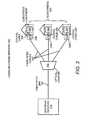
- FIG. 2illustrates a communications network 200 having a return path, in accordance with an embodiment of the present invention. While FIG. 2 depicts an HFC network, a person having ordinary skill in the art will appreciate that the embodiments described herein are applicable to other communication networks, including cable systems where fiber is provided to the subscriber's premises or any DOCSIS-compliant network.
- the communications network 200includes an upstream receiver 216 and a fiber optic link 104 .
- the upstream receiver 216may be any device for receiving an upstream transmission and may be similar to those used in a conventional HFC head-end 102 , described above with respect to FIG. 1 .
- the fiber optic link 104connects to an optical coupler 206 , which may be any multiplexer for receiving multiple inputs and combining these multiple inputs into a single output.
- the multiple inputs received by the optical coupler 206originate from the subscribers 210 via fiber optic cables 204 .
- Each subscriber 210may include at least one piece of subscriber equipment 209 for generating a digital signal and converting the digital signal to a RF signal.
- the subscriber equipment 209may include DOCSIS compliant equipment located inside the subscriber's premises, such as a STB, cable modem, or MTA that is well known in the art.
- a person having ordinary skill in the artwill appreciate that not every subscriber 110 may have subscriber equipment 209 for generating upstream signals.
- the RF signal generated by the subscriber equipment 209may be transmitted to an ONT 212 via coaxial cable 208 .
- the ONT 212may include any hardware and/or software for receiving a RF signal, demodulating the RF signal, and converting the demodulated signal into an optical transmission, as will be described in greater detail below.
- the ONT 212may be in the form of a utility box located on an outer wall of a premise of the subscriber, as depicted in FIG. 2 .
- the physical location of the ONT 212 in relation to a subscriberis not critical and that the ONT 212 may be located on the interior of a subscriber, such as a home, or may be located any reasonably suitable distance outside of the subscriber's premises. Wherever its location, the ONT 212 and the subscriber equipment 209 may be connected via the coaxial cable 208 , such that the RF signal generated by the subscriber equipment 209 may be transmitted from the subscriber equipment 209 to the ONT 212 .
- the ONT 212may select the upstream data signal from the composite RF spectrum, demodulate the upstream data signal into a baseband digital signal, and convert the baseband digital signal into an optical signal for transmission to the optical coupler 206 via the fiber optic cable link 204 .
- the ONT 212instead of having to convert a modulated RF signal into an optical signal, the ONT 212 only has to convert the baseband digital signal that has been demodulated from the RF signal. This substantially reduces the bandwidth requirement for transmission of the upstream data signal back to the head-end.
- FIG. 2depicts the optical coupler 206 receiving input signals from three ONT's 212
- the optical coupler 206is configurable to receive optical signals from any suitable number of ONT's 212
- the communications network 200 depicted in FIG. 2shows the optical coupler 206 connected directly to the upstream receiver 216 .
- the optical coupler 206may be connected to any other components in, or external to, the head-end 102 , which are capable of receiving optical signals.
- the communications network 200may not include an optical coupler 206 .
- each ONT 212may be in connection with other devices or in direct connection with the upstream receiver 216 .
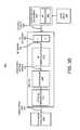
- FIGS. 3A and 3Bdepict the same communications network 200 with more detailed illustrations of the ONT 212 and the subscriber equipment 209 , in accordance with embodiments.
- data flowbegins on the right side of the communications network 200 .
- User input 302is received at the subscriber equipment 209 .
- user input 302may include the selection of a media program from an on-demand service, an email sent from a user's home computer, a VoIP phone call, etc.
- the user input 302may be received by the subscriber equipment 209 in any suitable manner, such as by infra red (IR) beam from a user's remote control, or electrical signals generated from a keyboard, mouse, computer, Internet phone, or any other user interface of the subscriber equipment 209 .
- the user input 302may also include communications which occur automatically as a normal operating function of the subscriber equipment 209 .
- the subscriber equipment 209may be any device for generating an upstream data signal.
- the subscriber equipment 209may create a baseband digital signal. This baseband digital signal may be modulated and impressed upon an RF carrier signal by the RF modulator 309 .
- the subscriber equipment 209is operable to output the upstream data signal as an RF signal on one or more frequency bands or channels.
- the upstream data signalis a baseband digital signal impressed on the 5-7 MHz frequency band.
- the RF modulator 309may be any device known in the art, which is capable of modulating and impressing a digital signal onto an RF carrier signal for transmission.
- the subscriber equipment 209may transmit the RF signal to the ONT 212 via the coaxial cable 208 .
- the ONT 212includes an RF diplexer 304 , an RF demodulator 310 , and an optical transducer 314 .
- the RF diplexer or combiner 304may be any device for receiving, combining or separating, and re-routing RF signals.
- the RF diplexer 304may separate and re-route the upstream and downstream signals in the communications network 200 based on their frequency. For example, low frequencies ranging from about 5 MHz to about 42 MHz, are generally designated for upstream signaling, while higher frequencies ranging from about 42 MHz to about 1000 MHz are designated for forward path, or downstream signaling.
- the “L” and the “H” depicted in the RF diplexer 304represent low and high frequency ranges for upstream and downstream signalings, respectively. Because the ONT 212 is operable to receiving both downstream signals from the head-end and upstream signals from the subscriber equipment 209 , the RF diplexer 304 is operable to separate the low-frequency signals as upstream signals for output to the RF demodulator 310 .
- the communication protocols already inherent in the RF signals generated by the subscriber equipment 209are used to assure proper timing.
- any RF signals that share a single return or upstream channel in the communications network 200are carried directly by the same scheme as described in the following scenario.
- their signalsmay be controlled by an existing multiple-access protocol such as time division multiple access (TDMA) for modulation, which allow them to be demodulated by a single receiver at the subscriber's premises and then transmitted as a single bit stream on the fiber optic link 204 .
- TDMAtime division multiple access
- the single receiveris the ONT 212 , with an RF demodulator 310 therein to facilitate the aforementioned demodulation.
- the RF upstream data signalis separated by the RF diplexer 304 and output to the RF demodulator 310 , it is demodulated by the RF demodulator 310 into a baseband digital signal 312 , which is the basic data or information sent by the subscriber equipment 209 .
- the RF demodulator 310may be any device for demodulating an RF signal to recover the original signal carried by the RF signal.
- the baseband digital signal 312is then converted by the optical transducer 314 into an optical signal.
- the optical transducer 312may be any device that is operable to convert a non-optical signal into an optical signal.
- the optical transducer 312may include a laser device, such as a laser diode, which is operable to convert the baseband digital signal 312 received from the RF demodulator 310 into an optical signal, which is then transmitted over the fiber optic link 204 to an upstream receiver 216 .
- the optical transducer 312is further described with reference to FIG. 4 below.
- the upstream receiver 216may be any device for receiving and processing optical upstream signals.
- the upstream receiver 216may be a part of the head-end 102 .
- the ONT 212may or may not transmit the optical signal directly to the upstream receiver 316 , because various components, such as multiplexers and optical couplers may be present in the upstream path between the upstream receiver 216 and the ONT 212 .
- FIG. 3Bdepicts another embodiment which allows for higher transmission rates at a single wavelength in the fiberoptic link 204 .
- This embodimentis similar to the aforementioned embodiment in FIG. 3A .
- the modulation rate at the optical transducer 314may be increased, for example, by some multiple.
- the ONT 214 at each subscriber 110is similar to the ONT 212 in FIG. 3A , except that it further includes a controller 308 , which may be hardware and/or software implemented so as to be operable to combine the various data streams from the RF demodulator 310 in a TDMA manner for input into the optical transducer 314 as described above with reference to FIG. 3A .
- the controller 308allows for the combining of multiple signals at different RF frequencies generated from a single subscriber 110 or multiple signals at different RF frequencies generated from multiple subscribers 110 . All incoming signals may be buffered for a certain time period, regardless of their origin and RF frequency, and the controller 308 combines the demodulated data signals from the incoming signals for transmission at a higher rate (e.g., 100 ⁇ a received rate) by the optical transducer 314 . The controller 308 may determine when to transmit this high speed signal based on the RF frequency that the original signal arrived at. While the controller 308 is depicted in FIG. 3B as an independent component, a person having ordinary skill in the art will appreciate that the controller 308 may be an integral component of either the RF demodulator 310 or the optical transducer 314 .
- the aforementioned ONTs 212 and 214allow upstream data signals, in essence, to be stripped to it's basic component, i.e., the baseband digital signal 312 as originally generated by the subscriber equipment 209 .
- the ONTs 212 and 214prevent the transmission of the RF carrier signals over the fiber optic link 204 , which would have required substantially more bandwidth for such a transmission and would require an external means for timing and control of the optical transmission.
- the ONTs 212 and 214provide a more efficient and effective scheme for upstream signaling in the communications network 200 .
- an upstream data signal of tens of megabitsmay be transmitted instead of the typical 2-3 gigabytes required to conventionally transmit the entire upstream RF spectrum.
- the adherence of such signals to DOCSIS or similar protocolsmay continue to allow for proper distance ranging and RF power control and to hand such signals directly to the baseband interface in the CMTS at the head-end.
- FIG. 4illustrates an optical transducer 314 for use in both the ONTs 212 or 214 , in accordance with one embodiment of the present invention.
- the optical transducer 314may be an optical multiplexer, such as an optical triplexer as illustrated in FIG. 4 .
- the optical transducer 314includes a first and second optical receiver 406 and 410 , respectively, and an optical transmitter 408 .
- the baseband digital signal 312may be received from the RF demodulator 310 at the optical transmitter 408 .
- the optical transmitter 408(e.g., with a laser diode therein) is operable to convert the baseband digital signal 312 into an optical signal, which is then transmitted to the upstream receiver 216 .
- the optical transducer 314may also receive optical signals that are sent from the head-end 102 for downstream signaling, for example, at the first and second optical receivers 406 and 410 .
- the first optical receiver 406may receive optical signals at one wavelength of light (e.g., 1490 nm wavelength) for downstream signaling at the ancillary 412 .
- the optical transmitter 408may transmit optical signals at a different wavelength of light (e.g., 1310 nm wavelength) for upstream signaling.
- the second optical receiver 410also may receive optical signals, which may be additional downstream signals 414 , at a wavelength different from that received by the first optical receiver 406 (e.g., 1550 nm wavelength).
- the downstream signals 412may be ancillary signals
- the downstream signals 414may include media content sent from the head-end to the subscribers 110 , such as but not limited to television, movies, and Internet data, etc.
- the optical signals from the ONTs 212 and 214 at the subscriber's premisesmay be optically combined in an optical coupler, such as the optical coupler 206 depicted in FIG. 2 , and may eventually end up at a collector node, hub, or similar device.
- the combined digital optical signalsdo not suffer from carrier-to-noise degradation or multiple optical carrier interference because only one laser or optical transducer 314 transmits at a time.
- the various embodiments described hereinprovide an “open loop” upstream return path, because no new timing information is needed to transmit the upstream signals. That is, the timing and control information for the upstream signals is already present in the downstream DOCSIS signals.
- the embodiments described hereinprovide an efficient method for MSOs to utilize existing DOCSIS-compliant networks to enhance upstream signaling.
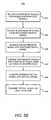
- FIGS. 5A-Bdepicts a process flows or methods 500 and 550 , respectively, for facilitating the transmission of an upstream data signal, in accordance with one embodiment of the present invention.
- the methods 500 and 550are described with respect to FIGS. 2 and 3 A-B by way of example and not limitation and it will be apparent that the methods 500 and 550 may be used in other HFC networks.
- certain steps in the method 500are optional and that an upstream data signal may be transmitted without practicing certain steps illustrated in FIGS. 5A-B .
- additional stepsmay be inherent or added to the methods 500 and 550 .
- an upstream RF signal containing an upstream data signalis received by the ONT 212 at the diplexer 304 .
- the upstream data signalmay be in a particular frequency band or channel as defined by DOCSIS.
- the baseband digital signalmay be generated by a subscriber equipment 209 , which is then impressed on an RF carrier signal by the RF modulator 309 ( FIG. 3A ), which may be in response to the receipt of a user input 302 or may be automatically generated by the subscriber equipment 209 at the subscriber's premises.
- the diplexer 304separates the upstream RF signal from any downstream RF signal based on the frequencies of the two signals, as described earlier, so as to forward the upstream RF signal to the RF demodulator 310 and the downstream RF signal to the subscriber equipment 209 .
- the RF signal received from the diplexer 304is demodulated into its original baseband digital signal.
- the baseband digital signalis then converted into an optical signal.
- the optical signalmay be generated by an optical transducer 314 , having an optical transmitter 408 .
- the optical signalis transmitted by the optical transducer 314 via the fiber optic link 204 to an upstream receiver 216 .
- the upstream receiver 216may be located at the head-end 102 and may process the upstream data signal.
- FIG. 5Bdepicts a method 550 that is similar to the method 500 in FIG. 5A , except with the addition of block 507 in between blocks 506 and 508 , for combining baseband digital signals from multiple pieces of subscriber equipment 209 .
- the multiple pieces of subscriber equipment 209may be physically located at a single subscriber 110 or the multiple pieces of subscriber equipment 209 may be located at multiple subscribers 110 .
- the controller 308combines the various digital signals from the multiple pieces of subscriber equipment 209 in a TDMA manner, or in accordance with any other multiple access protocol, for input into the optical transducer 314 .
- such signal combinationsallow the optical transducer 314 to modulate signals at rates that are different from the rates of the various subscriber equipment 209 that provide input to each ONT 214 .
- Thisallows the multiple pieces of subscriber equipment 209 to transmit at the same time at their individual lower rates, and then have those signals combined, for example, in a TDMA manner at the controller 308 .
- embodiments of the present inventionprovide effective and efficient schemes for the transmission of upstream or return-path signals, e.g., from the subscribers to the head-ends, in an HFC network.
- upstream or return-path signalse.g., from the subscribers to the head-ends
- DOCSIS-compliant protocole.g., DOCSIS-compliant protocol
Landscapes
- Engineering & Computer Science (AREA)
- Multimedia (AREA)
- Signal Processing (AREA)
- Physics & Mathematics (AREA)
- Electromagnetism (AREA)
- Computer Networks & Wireless Communication (AREA)
- Optical Communication System (AREA)
- Small-Scale Networks (AREA)
Abstract
Description
Claims (13)
Priority Applications (3)
| Application Number | Priority Date | Filing Date | Title |
|---|---|---|---|
| US11/616,951US8978085B2 (en) | 2006-12-28 | 2006-12-28 | Return data path in an HFC network |
| CA2609168ACA2609168C (en) | 2006-12-28 | 2007-11-01 | Return data path in an hfc network |
| MX2007016142AMX2007016142A (en) | 2006-12-28 | 2007-12-17 | Demodulated digital upstream transmission. |
Applications Claiming Priority (1)
| Application Number | Priority Date | Filing Date | Title |
|---|---|---|---|
| US11/616,951US8978085B2 (en) | 2006-12-28 | 2006-12-28 | Return data path in an HFC network |
Publications (2)
| Publication Number | Publication Date |
|---|---|
| US20120198510A1 US20120198510A1 (en) | 2012-08-02 |
| US8978085B2true US8978085B2 (en) | 2015-03-10 |
Family
ID=39551476
Family Applications (1)
| Application Number | Title | Priority Date | Filing Date |
|---|---|---|---|
| US11/616,951Active2031-07-06US8978085B2 (en) | 2006-12-28 | 2006-12-28 | Return data path in an HFC network |
Country Status (3)
| Country | Link |
|---|---|
| US (1) | US8978085B2 (en) |
| CA (1) | CA2609168C (en) |
| MX (1) | MX2007016142A (en) |
Families Citing this family (19)
| Publication number | Priority date | Publication date | Assignee | Title |
|---|---|---|---|---|
| US8526490B2 (en) | 2002-12-10 | 2013-09-03 | Ol2, Inc. | System and method for video compression using feedback including data related to the successful receipt of video content |
| US8711923B2 (en) | 2002-12-10 | 2014-04-29 | Ol2, Inc. | System and method for selecting a video encoding format based on feedback data |
| US9061207B2 (en) | 2002-12-10 | 2015-06-23 | Sony Computer Entertainment America Llc | Temporary decoder apparatus and method |
| US20090118019A1 (en) | 2002-12-10 | 2009-05-07 | Onlive, Inc. | System for streaming databases serving real-time applications used through streaming interactive video |
| US9077991B2 (en) | 2002-12-10 | 2015-07-07 | Sony Computer Entertainment America Llc | System and method for utilizing forward error correction with video compression |
| US10201760B2 (en) | 2002-12-10 | 2019-02-12 | Sony Interactive Entertainment America Llc | System and method for compressing video based on detected intraframe motion |
| US8549574B2 (en)* | 2002-12-10 | 2013-10-01 | Ol2, Inc. | Method of combining linear content and interactive content compressed together as streaming interactive video |
| US9192859B2 (en)* | 2002-12-10 | 2015-11-24 | Sony Computer Entertainment America Llc | System and method for compressing video based on latency measurements and other feedback |
| US9138644B2 (en) | 2002-12-10 | 2015-09-22 | Sony Computer Entertainment America Llc | System and method for accelerated machine switching |
| US8964830B2 (en) | 2002-12-10 | 2015-02-24 | Ol2, Inc. | System and method for multi-stream video compression using multiple encoding formats |
| US9446305B2 (en) | 2002-12-10 | 2016-09-20 | Sony Interactive Entertainment America Llc | System and method for improving the graphics performance of hosted applications |
| US9108107B2 (en)* | 2002-12-10 | 2015-08-18 | Sony Computer Entertainment America Llc | Hosting and broadcasting virtual events using streaming interactive video |
| US9314691B2 (en)* | 2002-12-10 | 2016-04-19 | Sony Computer Entertainment America Llc | System and method for compressing video frames or portions thereof based on feedback information from a client device |
| US8406629B2 (en) | 2006-11-22 | 2013-03-26 | General Instrument Corporation | Architecture to communicate with standard hybrid fiber coaxial RF signals over a passive optical network (HFC PON) |
| US20090049492A1 (en)* | 2007-08-17 | 2009-02-19 | Niki Pantelias | Network Architecture and Devices for Improving Performance of Hybrid Fiber Coax Cable Data Systems |
| US9168457B2 (en) | 2010-09-14 | 2015-10-27 | Sony Computer Entertainment America Llc | System and method for retaining system state |
| US8493986B2 (en)* | 2010-05-17 | 2013-07-23 | Cox Communications, Inc. | Service gateways for providing broadband communication |
| US9917648B2 (en) | 2014-10-01 | 2018-03-13 | Arris Enterprises Llc | Upstream interference eliminating transmission of digital baseband signal in an optical network |
| US10873366B2 (en)* | 2018-04-16 | 2020-12-22 | Intel Corporation | Virtual distribution point architecture |
Citations (9)
| Publication number | Priority date | Publication date | Assignee | Title |
|---|---|---|---|---|
| US5138440A (en) | 1990-10-29 | 1992-08-11 | General Instrument Corporation | Method and apparatus for communicating a plurality of asynchronous signals over a digital communication path |
| EP0840470A2 (en) | 1996-10-31 | 1998-05-06 | Alcatel | Optical network termination of a hybrid fiberoptic-coaxial access network |
| US5854703A (en) | 1997-02-28 | 1998-12-29 | Scientific-Atlanta, Inc. | Hybrid fiber coax communications network |
| WO2001095626A2 (en) | 2000-06-02 | 2001-12-13 | General Instrument Corporation | A system for improved return path performance for digital communication signals |
| US20010055319A1 (en)* | 1998-10-30 | 2001-12-27 | Broadcom Corporation | Robust techniques for optimal upstream communication between cable modem subscribers and a headend |
| US20030028897A1 (en) | 2001-08-06 | 2003-02-06 | Brooks Paul D. | Technique for reverse transport of data in a hybrid fiber coax cable system |
| US20030194241A1 (en)* | 2001-07-05 | 2003-10-16 | Wave7 Optics, Inc. | Method and system for providing a return data path for legacy terminals by using existing electrical waveguides of a structure |
| US20050022247A1 (en)* | 2003-07-24 | 2005-01-27 | Yigal Bitran | Set-top box including a single tuner for video and data over cable |
| US20080056713A1 (en)* | 2006-09-05 | 2008-03-06 | Cooper Michael J | Efficient Use of Trusted Third Parties for Additional Content-Sharing Security |
- 2006
- 2006-12-28USUS11/616,951patent/US8978085B2/enactiveActive
- 2007
- 2007-11-01CACA2609168Apatent/CA2609168C/enactiveActive
- 2007-12-17MXMX2007016142Apatent/MX2007016142A/enactiveIP Right Grant
Patent Citations (10)
| Publication number | Priority date | Publication date | Assignee | Title |
|---|---|---|---|---|
| US5138440A (en) | 1990-10-29 | 1992-08-11 | General Instrument Corporation | Method and apparatus for communicating a plurality of asynchronous signals over a digital communication path |
| EP0840470A2 (en) | 1996-10-31 | 1998-05-06 | Alcatel | Optical network termination of a hybrid fiberoptic-coaxial access network |
| US6134035A (en) | 1996-10-31 | 2000-10-17 | Alcatel | Optical network termination unit of a hybrid fiber/coax access network |
| US5854703A (en) | 1997-02-28 | 1998-12-29 | Scientific-Atlanta, Inc. | Hybrid fiber coax communications network |
| US20010055319A1 (en)* | 1998-10-30 | 2001-12-27 | Broadcom Corporation | Robust techniques for optimal upstream communication between cable modem subscribers and a headend |
| WO2001095626A2 (en) | 2000-06-02 | 2001-12-13 | General Instrument Corporation | A system for improved return path performance for digital communication signals |
| US20030194241A1 (en)* | 2001-07-05 | 2003-10-16 | Wave7 Optics, Inc. | Method and system for providing a return data path for legacy terminals by using existing electrical waveguides of a structure |
| US20030028897A1 (en) | 2001-08-06 | 2003-02-06 | Brooks Paul D. | Technique for reverse transport of data in a hybrid fiber coax cable system |
| US20050022247A1 (en)* | 2003-07-24 | 2005-01-27 | Yigal Bitran | Set-top box including a single tuner for video and data over cable |
| US20080056713A1 (en)* | 2006-09-05 | 2008-03-06 | Cooper Michael J | Efficient Use of Trusted Third Parties for Additional Content-Sharing Security |
Non-Patent Citations (7)
| Title |
|---|
| Canadian Intellectual Property Office, "Official Action-Rejection" for Canadian Application No. 2,609,168 Aug. 12, 2011, 2 pages. |
| Canadian Intellectual Property Office, "Official Action—Rejection" for Canadian Application No. 2,609,168 Aug. 12, 2011, 2 pages. |
| Notice of Allowance mailed on Aug. 8, 2013 in Canadian Patent Application CA2609168. |
| Office Action mailed on Dec. 5, 2012 in Canadian Patent Application CA2609168. |
| Office Action mailed on Mar. 1, 2012 in Mexican Patent Application MX/a/2007/016142. |
| Office Action mailed on Mar. 21, 2012 in Canadian Patent Application CA2609168. |
| Office Action mailed on Sep. 5, 2011 in Mexican Patent Application MX/a/2007/016142. |
Also Published As
| Publication number | Publication date |
|---|---|
| MX2007016142A (en) | 2009-02-23 |
| CA2609168A1 (en) | 2008-06-28 |
| CA2609168C (en) | 2013-12-24 |
| US20120198510A1 (en) | 2012-08-02 |
Similar Documents
| Publication | Publication Date | Title |
|---|---|---|
| US8978085B2 (en) | Return data path in an HFC network | |
| US6577414B1 (en) | Subcarrier modulation fiber-to-the-home/curb (FTTH/C) access system providing broadband communications | |
| US8050562B2 (en) | Apparatus for implementing electro-optical CATV network and signal processing method used by the apparatus | |
| US7088921B1 (en) | System for operating an Ethernet data network over a passive optical network access system | |
| US8406629B2 (en) | Architecture to communicate with standard hybrid fiber coaxial RF signals over a passive optical network (HFC PON) | |
| US20080310842A1 (en) | Docsis compatible pon architecture | |
| US6775433B2 (en) | Deep fiber network with high speed data and video on demand | |
| US20130125194A1 (en) | Converged Cable Access Platform for Provision of Video and Data Services | |
| US20030128983A1 (en) | Digital RF return over fiber | |
| US20250106538A1 (en) | Hybrid Fiber Coaxial Node | |
| US20050183131A1 (en) | System and method for providing integrated communications and broadcasting service | |
| US20040264974A1 (en) | Cable television passive optical network | |
| US7197205B1 (en) | Deep fiber network with high speed data and video on demand | |
| US20030063847A1 (en) | Deep fiber network architecture | |
| Wilson et al. | FiberVista: An FTTH or FTTC system delivering broadband data and CATV services | |
| van Veen et al. | An analysis of the technical and economic essentials for providing video over fiber-to-the-premises networks | |
| Jewell et al. | Cable TV technology for local access | |
| EP1314318A1 (en) | Transceiver applications in hfc networks | |
| US20190104334A1 (en) | Cable modem with embedded video transmitter | |
| US9391819B1 (en) | Systems and methods for preventing energy leakage in communications systems | |
| JPWO2007083384A1 (en) | Unidirectional transmission signal distribution method, station side apparatus and subscriber premises side apparatus in passive optical network system | |
| WO2008070441A1 (en) | Architecture to communicate with standard hybrid fiber coaxial rf signals over a passive optical network (hfc pon) | |
| Lu et al. | The evolution of Cable TV networks | |
| Arpaci et al. | Providing integrated services with broadband PON | |
| Bahr | A Comprehensive Study of Price |
Legal Events
| Date | Code | Title | Description |
|---|---|---|---|
| AS | Assignment | Owner name:GENERAL INSTRUMENT CORPORATION, PENNSYLVANIA Free format text:ASSIGNMENT OF ASSIGNORS INTEREST;ASSIGNORS:STONEBACK, DEAN A.;FREDERICK, STEVEN F.;PICARD, GARY A.;SIGNING DATES FROM 20061219 TO 20070108;REEL/FRAME:019191/0811 | |
| AS | Assignment | Owner name:BANK OF AMERICA, N.A., AS ADMINISTRATIVE AGENT, IL Free format text:SECURITY AGREEMENT;ASSIGNORS:ARRIS GROUP, INC.;ARRIS ENTERPRISES, INC.;ARRIS SOLUTIONS, INC.;AND OTHERS;REEL/FRAME:030498/0023 Effective date:20130417 Owner name:BANK OF AMERICA, N.A., AS ADMINISTRATIVE AGENT, ILLINOIS Free format text:SECURITY AGREEMENT;ASSIGNORS:ARRIS GROUP, INC.;ARRIS ENTERPRISES, INC.;ARRIS SOLUTIONS, INC.;AND OTHERS;REEL/FRAME:030498/0023 Effective date:20130417 | |
| STCF | Information on status: patent grant | Free format text:PATENTED CASE | |
| AS | Assignment | Owner name:ARRIS TECHNOLOGY, INC., GEORGIA Free format text:MERGER AND CHANGE OF NAME;ASSIGNOR:GENERAL INSTRUMENT CORPORATION;REEL/FRAME:035176/0620 Effective date:20150101 Owner name:ARRIS TECHNOLOGY, INC., GEORGIA Free format text:MERGER AND CHANGE OF NAME;ASSIGNORS:GENERAL INSTRUMENT CORPORATION;GENERAL INSTRUMENT CORPORATION;REEL/FRAME:035176/0620 Effective date:20150101 | |
| AS | Assignment | Owner name:ARRIS ENTERPRISES, INC., GEORGIA Free format text:ASSIGNMENT OF ASSIGNORS INTEREST;ASSIGNOR:ARRIS TECHNOLOGY, INC;REEL/FRAME:037328/0341 Effective date:20151214 | |
| MAFP | Maintenance fee payment | Free format text:PAYMENT OF MAINTENANCE FEE, 4TH YEAR, LARGE ENTITY (ORIGINAL EVENT CODE: M1551); ENTITY STATUS OF PATENT OWNER: LARGE ENTITY Year of fee payment:4 | |
| AS | Assignment | Owner name:ARRIS SOLUTIONS, INC., PENNSYLVANIA Free format text:TERMINATION AND RELEASE OF SECURITY INTEREST IN PATENTS;ASSIGNOR:BANK OF AMERICA, N.A., AS ADMINISTRATIVE AGENT;REEL/FRAME:048825/0294 Effective date:20190404 Owner name:ACADIA AIC, INC., PENNSYLVANIA Free format text:TERMINATION AND RELEASE OF SECURITY INTEREST IN PATENTS;ASSIGNOR:BANK OF AMERICA, N.A., AS ADMINISTRATIVE AGENT;REEL/FRAME:048825/0294 Effective date:20190404 Owner name:ARRIS ENTERPRISES, INC., PENNSYLVANIA Free format text:TERMINATION AND RELEASE OF SECURITY INTEREST IN PATENTS;ASSIGNOR:BANK OF AMERICA, N.A., AS ADMINISTRATIVE AGENT;REEL/FRAME:048825/0294 Effective date:20190404 Owner name:AEROCAST, INC., PENNSYLVANIA Free format text:TERMINATION AND RELEASE OF SECURITY INTEREST IN PATENTS;ASSIGNOR:BANK OF AMERICA, N.A., AS ADMINISTRATIVE AGENT;REEL/FRAME:048825/0294 Effective date:20190404 Owner name:POWER GUARD, INC., PENNSYLVANIA Free format text:TERMINATION AND RELEASE OF SECURITY INTEREST IN PATENTS;ASSIGNOR:BANK OF AMERICA, N.A., AS ADMINISTRATIVE AGENT;REEL/FRAME:048825/0294 Effective date:20190404 Owner name:CCE SOFTWARE LLC, PENNSYLVANIA Free format text:TERMINATION AND RELEASE OF SECURITY INTEREST IN PATENTS;ASSIGNOR:BANK OF AMERICA, N.A., AS ADMINISTRATIVE AGENT;REEL/FRAME:048825/0294 Effective date:20190404 Owner name:4HOME, INC., PENNSYLVANIA Free format text:TERMINATION AND RELEASE OF SECURITY INTEREST IN PATENTS;ASSIGNOR:BANK OF AMERICA, N.A., AS ADMINISTRATIVE AGENT;REEL/FRAME:048825/0294 Effective date:20190404 Owner name:GIC INTERNATIONAL HOLDCO LLC, PENNSYLVANIA Free format text:TERMINATION AND RELEASE OF SECURITY INTEREST IN PATENTS;ASSIGNOR:BANK OF AMERICA, N.A., AS ADMINISTRATIVE AGENT;REEL/FRAME:048825/0294 Effective date:20190404 Owner name:NEXTLEVEL SYSTEMS (PUERTO RICO), INC., PENNSYLVANI Free format text:TERMINATION AND RELEASE OF SECURITY INTEREST IN PATENTS;ASSIGNOR:BANK OF AMERICA, N.A., AS ADMINISTRATIVE AGENT;REEL/FRAME:048825/0294 Effective date:20190404 Owner name:GENERAL INSTRUMENT INTERNATIONAL HOLDINGS, INC., P Free format text:TERMINATION AND RELEASE OF SECURITY INTEREST IN PATENTS;ASSIGNOR:BANK OF AMERICA, N.A., AS ADMINISTRATIVE AGENT;REEL/FRAME:048825/0294 Effective date:20190404 Owner name:BROADBUS TECHNOLOGIES, INC., PENNSYLVANIA Free format text:TERMINATION AND RELEASE OF SECURITY INTEREST IN PATENTS;ASSIGNOR:BANK OF AMERICA, N.A., AS ADMINISTRATIVE AGENT;REEL/FRAME:048825/0294 Effective date:20190404 Owner name:QUANTUM BRIDGE COMMUNICATIONS, INC., PENNSYLVANIA Free format text:TERMINATION AND RELEASE OF SECURITY INTEREST IN PATENTS;ASSIGNOR:BANK OF AMERICA, N.A., AS ADMINISTRATIVE AGENT;REEL/FRAME:048825/0294 Effective date:20190404 Owner name:MOTOROLA WIRELINE NETWORKS, INC., PENNSYLVANIA Free format text:TERMINATION AND RELEASE OF SECURITY INTEREST IN PATENTS;ASSIGNOR:BANK OF AMERICA, N.A., AS ADMINISTRATIVE AGENT;REEL/FRAME:048825/0294 Effective date:20190404 Owner name:MODULUS VIDEO, INC., PENNSYLVANIA Free format text:TERMINATION AND RELEASE OF SECURITY INTEREST IN PATENTS;ASSIGNOR:BANK OF AMERICA, N.A., AS ADMINISTRATIVE AGENT;REEL/FRAME:048825/0294 Effective date:20190404 Owner name:GIC INTERNATIONAL CAPITAL LLC, PENNSYLVANIA Free format text:TERMINATION AND RELEASE OF SECURITY INTEREST IN PATENTS;ASSIGNOR:BANK OF AMERICA, N.A., AS ADMINISTRATIVE AGENT;REEL/FRAME:048825/0294 Effective date:20190404 Owner name:SETJAM, INC., PENNSYLVANIA Free format text:TERMINATION AND RELEASE OF SECURITY INTEREST IN PATENTS;ASSIGNOR:BANK OF AMERICA, N.A., AS ADMINISTRATIVE AGENT;REEL/FRAME:048825/0294 Effective date:20190404 Owner name:GENERAL INSTRUMENT CORPORATION, PENNSYLVANIA Free format text:TERMINATION AND RELEASE OF SECURITY INTEREST IN PATENTS;ASSIGNOR:BANK OF AMERICA, N.A., AS ADMINISTRATIVE AGENT;REEL/FRAME:048825/0294 Effective date:20190404 Owner name:GENERAL INSTRUMENT AUTHORIZATION SERVICES, INC., P Free format text:TERMINATION AND RELEASE OF SECURITY INTEREST IN PATENTS;ASSIGNOR:BANK OF AMERICA, N.A., AS ADMINISTRATIVE AGENT;REEL/FRAME:048825/0294 Effective date:20190404 Owner name:SUNUP DESIGN SYSTEMS, INC., PENNSYLVANIA Free format text:TERMINATION AND RELEASE OF SECURITY INTEREST IN PATENTS;ASSIGNOR:BANK OF AMERICA, N.A., AS ADMINISTRATIVE AGENT;REEL/FRAME:048825/0294 Effective date:20190404 Owner name:THE GI REALTY TRUST 1996, PENNSYLVANIA Free format text:TERMINATION AND RELEASE OF SECURITY INTEREST IN PATENTS;ASSIGNOR:BANK OF AMERICA, N.A., AS ADMINISTRATIVE AGENT;REEL/FRAME:048825/0294 Effective date:20190404 Owner name:TEXSCAN CORPORATION, PENNSYLVANIA Free format text:TERMINATION AND RELEASE OF SECURITY INTEREST IN PATENTS;ASSIGNOR:BANK OF AMERICA, N.A., AS ADMINISTRATIVE AGENT;REEL/FRAME:048825/0294 Effective date:20190404 Owner name:LEAPSTONE SYSTEMS, INC., PENNSYLVANIA Free format text:TERMINATION AND RELEASE OF SECURITY INTEREST IN PATENTS;ASSIGNOR:BANK OF AMERICA, N.A., AS ADMINISTRATIVE AGENT;REEL/FRAME:048825/0294 Effective date:20190404 Owner name:ARRIS GROUP, INC., PENNSYLVANIA Free format text:TERMINATION AND RELEASE OF SECURITY INTEREST IN PATENTS;ASSIGNOR:BANK OF AMERICA, N.A., AS ADMINISTRATIVE AGENT;REEL/FRAME:048825/0294 Effective date:20190404 Owner name:ARRIS HOLDINGS CORP. OF ILLINOIS, INC., PENNSYLVAN Free format text:TERMINATION AND RELEASE OF SECURITY INTEREST IN PATENTS;ASSIGNOR:BANK OF AMERICA, N.A., AS ADMINISTRATIVE AGENT;REEL/FRAME:048825/0294 Effective date:20190404 Owner name:IMEDIA CORPORATION, PENNSYLVANIA Free format text:TERMINATION AND RELEASE OF SECURITY INTEREST IN PATENTS;ASSIGNOR:BANK OF AMERICA, N.A., AS ADMINISTRATIVE AGENT;REEL/FRAME:048825/0294 Effective date:20190404 Owner name:NETOPIA, INC., PENNSYLVANIA Free format text:TERMINATION AND RELEASE OF SECURITY INTEREST IN PATENTS;ASSIGNOR:BANK OF AMERICA, N.A., AS ADMINISTRATIVE AGENT;REEL/FRAME:048825/0294 Effective date:20190404 Owner name:ARRIS KOREA, INC., PENNSYLVANIA Free format text:TERMINATION AND RELEASE OF SECURITY INTEREST IN PATENTS;ASSIGNOR:BANK OF AMERICA, N.A., AS ADMINISTRATIVE AGENT;REEL/FRAME:048825/0294 Effective date:20190404 Owner name:BIG BAND NETWORKS, INC., PENNSYLVANIA Free format text:TERMINATION AND RELEASE OF SECURITY INTEREST IN PATENTS;ASSIGNOR:BANK OF AMERICA, N.A., AS ADMINISTRATIVE AGENT;REEL/FRAME:048825/0294 Effective date:20190404 Owner name:JERROLD DC RADIO, INC., PENNSYLVANIA Free format text:TERMINATION AND RELEASE OF SECURITY INTEREST IN PATENTS;ASSIGNOR:BANK OF AMERICA, N.A., AS ADMINISTRATIVE AGENT;REEL/FRAME:048825/0294 Effective date:20190404 Owner name:UCENTRIC SYSTEMS, INC., PENNSYLVANIA Free format text:TERMINATION AND RELEASE OF SECURITY INTEREST IN PATENTS;ASSIGNOR:BANK OF AMERICA, N.A., AS ADMINISTRATIVE AGENT;REEL/FRAME:048825/0294 Effective date:20190404 Owner name:ARRIS HOLDINGS CORP. OF ILLINOIS, INC., PENNSYLVANIA Free format text:TERMINATION AND RELEASE OF SECURITY INTEREST IN PATENTS;ASSIGNOR:BANK OF AMERICA, N.A., AS ADMINISTRATIVE AGENT;REEL/FRAME:048825/0294 Effective date:20190404 Owner name:NEXTLEVEL SYSTEMS (PUERTO RICO), INC., PENNSYLVANIA Free format text:TERMINATION AND RELEASE OF SECURITY INTEREST IN PATENTS;ASSIGNOR:BANK OF AMERICA, N.A., AS ADMINISTRATIVE AGENT;REEL/FRAME:048825/0294 Effective date:20190404 Owner name:GENERAL INSTRUMENT INTERNATIONAL HOLDINGS, INC., PENNSYLVANIA Free format text:TERMINATION AND RELEASE OF SECURITY INTEREST IN PATENTS;ASSIGNOR:BANK OF AMERICA, N.A., AS ADMINISTRATIVE AGENT;REEL/FRAME:048825/0294 Effective date:20190404 Owner name:GENERAL INSTRUMENT AUTHORIZATION SERVICES, INC., PENNSYLVANIA Free format text:TERMINATION AND RELEASE OF SECURITY INTEREST IN PATENTS;ASSIGNOR:BANK OF AMERICA, N.A., AS ADMINISTRATIVE AGENT;REEL/FRAME:048825/0294 Effective date:20190404 | |
| AS | Assignment | Owner name:ARRIS ENTERPRISES LLC, GEORGIA Free format text:CHANGE OF NAME;ASSIGNOR:ARRIS ENTERPRISES, INC.;REEL/FRAME:049649/0062 Effective date:20151231 | |
| AS | Assignment | Owner name:WILMINGTON TRUST, NATIONAL ASSOCIATION, AS COLLATE Free format text:PATENT SECURITY AGREEMENT;ASSIGNOR:ARRIS ENTERPRISES LLC;REEL/FRAME:049820/0495 Effective date:20190404 Owner name:JPMORGAN CHASE BANK, N.A., NEW YORK Free format text:TERM LOAN SECURITY AGREEMENT;ASSIGNORS:COMMSCOPE, INC. OF NORTH CAROLINA;COMMSCOPE TECHNOLOGIES LLC;ARRIS ENTERPRISES LLC;AND OTHERS;REEL/FRAME:049905/0504 Effective date:20190404 Owner name:JPMORGAN CHASE BANK, N.A., NEW YORK Free format text:ABL SECURITY AGREEMENT;ASSIGNORS:COMMSCOPE, INC. OF NORTH CAROLINA;COMMSCOPE TECHNOLOGIES LLC;ARRIS ENTERPRISES LLC;AND OTHERS;REEL/FRAME:049892/0396 Effective date:20190404 Owner name:WILMINGTON TRUST, NATIONAL ASSOCIATION, AS COLLATERAL AGENT, CONNECTICUT Free format text:PATENT SECURITY AGREEMENT;ASSIGNOR:ARRIS ENTERPRISES LLC;REEL/FRAME:049820/0495 Effective date:20190404 | |
| AS | Assignment | Owner name:WILMINGTON TRUST, DELAWARE Free format text:SECURITY INTEREST;ASSIGNORS:ARRIS SOLUTIONS, INC.;ARRIS ENTERPRISES LLC;COMMSCOPE TECHNOLOGIES LLC;AND OTHERS;REEL/FRAME:060752/0001 Effective date:20211115 | |
| AS | Assignment | Owner name:ARRIS ENTERPRISES, INC., GEORGIA Free format text:ASSIGNMENT OF ASSIGNORS INTEREST;ASSIGNOR:ARRIS TECHNOLOGY, INC.;REEL/FRAME:060791/0583 Effective date:20151214 | |
| MAFP | Maintenance fee payment | Free format text:PAYMENT OF MAINTENANCE FEE, 8TH YEAR, LARGE ENTITY (ORIGINAL EVENT CODE: M1552); ENTITY STATUS OF PATENT OWNER: LARGE ENTITY Year of fee payment:8 | |
| AS | Assignment | Owner name:APOLLO ADMINISTRATIVE AGENCY LLC, NEW YORK Free format text:SECURITY INTEREST;ASSIGNORS:ARRIS ENTERPRISES LLC;COMMSCOPE TECHNOLOGIES LLC;COMMSCOPE INC., OF NORTH CAROLINA;AND OTHERS;REEL/FRAME:069889/0114 Effective date:20241217 | |
| AS | Assignment | Owner name:RUCKUS WIRELESS, LLC (F/K/A RUCKUS WIRELESS, INC.), NORTH CAROLINA Free format text:RELEASE OF SECURITY INTEREST AT REEL/FRAME 049905/0504;ASSIGNOR:JPMORGAN CHASE BANK, N.A., AS COLLATERAL AGENT;REEL/FRAME:071477/0255 Effective date:20241217 Owner name:COMMSCOPE TECHNOLOGIES LLC, NORTH CAROLINA Free format text:RELEASE OF SECURITY INTEREST AT REEL/FRAME 049905/0504;ASSIGNOR:JPMORGAN CHASE BANK, N.A., AS COLLATERAL AGENT;REEL/FRAME:071477/0255 Effective date:20241217 Owner name:COMMSCOPE, INC. OF NORTH CAROLINA, NORTH CAROLINA Free format text:RELEASE OF SECURITY INTEREST AT REEL/FRAME 049905/0504;ASSIGNOR:JPMORGAN CHASE BANK, N.A., AS COLLATERAL AGENT;REEL/FRAME:071477/0255 Effective date:20241217 Owner name:ARRIS SOLUTIONS, INC., NORTH CAROLINA Free format text:RELEASE OF SECURITY INTEREST AT REEL/FRAME 049905/0504;ASSIGNOR:JPMORGAN CHASE BANK, N.A., AS COLLATERAL AGENT;REEL/FRAME:071477/0255 Effective date:20241217 Owner name:ARRIS TECHNOLOGY, INC., NORTH CAROLINA Free format text:RELEASE OF SECURITY INTEREST AT REEL/FRAME 049905/0504;ASSIGNOR:JPMORGAN CHASE BANK, N.A., AS COLLATERAL AGENT;REEL/FRAME:071477/0255 Effective date:20241217 Owner name:ARRIS ENTERPRISES LLC (F/K/A ARRIS ENTERPRISES, INC.), NORTH CAROLINA Free format text:RELEASE OF SECURITY INTEREST AT REEL/FRAME 049905/0504;ASSIGNOR:JPMORGAN CHASE BANK, N.A., AS COLLATERAL AGENT;REEL/FRAME:071477/0255 Effective date:20241217 |