US8977366B2 - Systems and methods for therapeutic electrical stimulation - Google Patents
Systems and methods for therapeutic electrical stimulationDownload PDFInfo
- Publication number
- US8977366B2 US8977366B2US14/322,838US201414322838AUS8977366B2US 8977366 B2US8977366 B2US 8977366B2US 201414322838 AUS201414322838 AUS 201414322838AUS 8977366 B2US8977366 B2US 8977366B2
- Authority
- US
- United States
- Prior art keywords
- controller
- patch
- shoe
- electrical
- receptacle
- Prior art date
- Legal status (The legal status is an assumption and is not a legal conclusion. Google has not performed a legal analysis and makes no representation as to the accuracy of the status listed.)
- Active
Links
- 230000001225therapeutic effectEffects0.000titleclaimsabstractdescription66
- 230000000638stimulationEffects0.000titleclaimsabstractdescription50
- 238000000034methodMethods0.000titledescription10
- 239000004020conductorSubstances0.000claimsabstractdescription28
- 238000003780insertionMethods0.000claimsabstractdescription5
- 230000037431insertionEffects0.000claimsabstractdescription4
- 238000002560therapeutic procedureMethods0.000claimsdescription51
- 238000002646transcutaneous electrical nerve stimulationMethods0.000claimsdescription16
- 230000029663wound healingEffects0.000claimsdescription6
- 206010030113OedemaDiseases0.000claimsdescription4
- 238000012377drug deliveryMethods0.000claimsdescription3
- 230000008878couplingEffects0.000claimsdescription2
- 238000010168coupling processMethods0.000claimsdescription2
- 238000005859coupling reactionMethods0.000claimsdescription2
- 238000011461current therapyMethods0.000claimsdescription2
- 230000009467reductionEffects0.000claimsdescription2
- 238000004891communicationMethods0.000description46
- 238000003032molecular dockingMethods0.000description43
- 239000010410layerSubstances0.000description26
- 239000012790adhesive layerSubstances0.000description14
- 208000002193PainDiseases0.000description10
- 230000036407painEffects0.000description10
- HBBGRARXTFLTSG-UHFFFAOYSA-NLithium ionChemical compound[Li+]HBBGRARXTFLTSG-UHFFFAOYSA-N0.000description7
- 238000010586diagramMethods0.000description7
- 229910001416lithium ionInorganic materials0.000description7
- 230000006870functionEffects0.000description6
- 230000008901benefitEffects0.000description5
- 238000013500data storageMethods0.000description5
- 230000000994depressogenic effectEffects0.000description5
- 230000000694effectsEffects0.000description5
- 210000003205muscleAnatomy0.000description5
- 239000000853adhesiveSubstances0.000description4
- 230000001070adhesive effectEffects0.000description4
- 230000006378damageEffects0.000description4
- 230000007423decreaseEffects0.000description4
- 229940079593drugDrugs0.000description4
- 239000003814drugSubstances0.000description4
- 239000012530fluidSubstances0.000description4
- 210000001624hipAnatomy0.000description4
- 210000003127kneeAnatomy0.000description4
- 238000012545processingMethods0.000description4
- XLYOFNOQVPJJNP-UHFFFAOYSA-NwaterSubstancesOXLYOFNOQVPJJNP-UHFFFAOYSA-N0.000description4
- 208000027418Wounds and injuryDiseases0.000description3
- 238000005516engineering processMethods0.000description3
- 230000001939inductive effectEffects0.000description3
- 238000007726management methodMethods0.000description3
- 230000007246mechanismEffects0.000description3
- 238000000465mouldingMethods0.000description3
- 230000006855networkingEffects0.000description3
- 230000002829reductive effectEffects0.000description3
- 102000009025EndorphinsHuman genes0.000description2
- 108010049140EndorphinsProteins0.000description2
- 206010028347Muscle twitchingDiseases0.000description2
- 208000000114Pain ThresholdDiseases0.000description2
- 206010052428WoundDiseases0.000description2
- OJIJEKBXJYRIBZ-UHFFFAOYSA-Ncadmium nickelChemical compound[Ni].[Cd]OJIJEKBXJYRIBZ-UHFFFAOYSA-N0.000description2
- 239000003990capacitorSubstances0.000description2
- 230000003467diminishing effectEffects0.000description2
- 210000002683footAnatomy0.000description2
- 239000007789gasSubstances0.000description2
- 239000004973liquid crystal related substanceSubstances0.000description2
- 239000000463materialSubstances0.000description2
- 230000013011matingEffects0.000description2
- 229910052751metalInorganic materials0.000description2
- 239000002184metalSubstances0.000description2
- 229910052987metal hydrideInorganic materials0.000description2
- 238000012544monitoring processMethods0.000description2
- 229910052759nickelInorganic materials0.000description2
- PXHVJJICTQNCMI-UHFFFAOYSA-NnickelSubstances[Ni]PXHVJJICTQNCMI-UHFFFAOYSA-N0.000description2
- -1nickel metal hydrideChemical class0.000description2
- 230000037040pain thresholdEffects0.000description2
- 239000002245particleSubstances0.000description2
- 238000002360preparation methodMethods0.000description2
- 230000001681protective effectEffects0.000description2
- 230000008961swellingEffects0.000description2
- 230000001360synchronised effectEffects0.000description2
- 238000012546transferMethods0.000description2
- 210000000689upper legAnatomy0.000description2
- 238000003466weldingMethods0.000description2
- 208000006820ArthralgiaDiseases0.000description1
- 208000001294Nociceptive PainDiseases0.000description1
- 230000005856abnormalityEffects0.000description1
- 230000002745absorbentEffects0.000description1
- 239000002250absorbentSubstances0.000description1
- WYTGDNHDOZPMIW-RCBQFDQVSA-NalstonineNatural productsC1=CC2=C3C=CC=CC3=NC2=C2N1C[C@H]1[C@H](C)OC=C(C(=O)OC)[C@H]1C2WYTGDNHDOZPMIW-RCBQFDQVSA-N0.000description1
- 238000004458analytical methodMethods0.000description1
- 210000003484anatomyAnatomy0.000description1
- 210000003423ankleAnatomy0.000description1
- 238000003491arrayMethods0.000description1
- 230000000712assemblyEffects0.000description1
- 238000000429assemblyMethods0.000description1
- 239000012867bioactive agentSubstances0.000description1
- 230000005540biological transmissionEffects0.000description1
- 230000008859changeEffects0.000description1
- 230000000295complement effectEffects0.000description1
- 238000012937correctionMethods0.000description1
- 230000003247decreasing effectEffects0.000description1
- 230000006735deficitEffects0.000description1
- 230000000881depressing effectEffects0.000description1
- 238000001514detection methodMethods0.000description1
- 230000009977dual effectEffects0.000description1
- 210000001513elbowAnatomy0.000description1
- 238000001914filtrationMethods0.000description1
- 230000005484gravityEffects0.000description1
- 238000010348incorporationMethods0.000description1
- 208000014674injuryDiseases0.000description1
- 238000009434installationMethods0.000description1
- 210000002414legAnatomy0.000description1
- 230000000670limiting effectEffects0.000description1
- 238000012986modificationMethods0.000description1
- 230000004048modificationEffects0.000description1
- 230000002232neuromuscularEffects0.000description1
- 229940124641pain relieverDrugs0.000description1
- 210000001428peripheral nervous systemAnatomy0.000description1
- 230000008569processEffects0.000description1
- 230000002441reversible effectEffects0.000description1
- 238000012552reviewMethods0.000description1
- 230000035939shockEffects0.000description1
- 210000002832shoulderAnatomy0.000description1
- 208000024891symptomDiseases0.000description1
- 210000001519tissueAnatomy0.000description1
- 238000011282treatmentMethods0.000description1
- 230000000007visual effectEffects0.000description1
- 210000000707wristAnatomy0.000description1
Images


Classifications
- A—HUMAN NECESSITIES
- A61—MEDICAL OR VETERINARY SCIENCE; HYGIENE
- A61N—ELECTROTHERAPY; MAGNETOTHERAPY; RADIATION THERAPY; ULTRASOUND THERAPY
- A61N1/00—Electrotherapy; Circuits therefor
- A61N1/02—Details
- A61N1/025—Digital circuitry features of electrotherapy devices, e.g. memory, clocks, processors
- A—HUMAN NECESSITIES
- A61—MEDICAL OR VETERINARY SCIENCE; HYGIENE
- A61N—ELECTROTHERAPY; MAGNETOTHERAPY; RADIATION THERAPY; ULTRASOUND THERAPY
- A61N1/00—Electrotherapy; Circuits therefor
- A61N1/02—Details
- A61N1/04—Electrodes
- A61N1/0404—Electrodes for external use
- A61N1/0408—Use-related aspects
- A61N1/0412—Specially adapted for transcutaneous electroporation, e.g. including drug reservoirs
- A—HUMAN NECESSITIES
- A61—MEDICAL OR VETERINARY SCIENCE; HYGIENE
- A61N—ELECTROTHERAPY; MAGNETOTHERAPY; RADIATION THERAPY; ULTRASOUND THERAPY
- A61N1/00—Electrotherapy; Circuits therefor
- A61N1/02—Details
- A61N1/04—Electrodes
- A61N1/0404—Electrodes for external use
- A61N1/0408—Use-related aspects
- A61N1/0428—Specially adapted for iontophoresis, e.g. AC, DC or including drug reservoirs
- A—HUMAN NECESSITIES
- A61—MEDICAL OR VETERINARY SCIENCE; HYGIENE
- A61N—ELECTROTHERAPY; MAGNETOTHERAPY; RADIATION THERAPY; ULTRASOUND THERAPY
- A61N1/00—Electrotherapy; Circuits therefor
- A61N1/02—Details
- A61N1/04—Electrodes
- A61N1/0404—Electrodes for external use
- A61N1/0408—Use-related aspects
- A61N1/0452—Specially adapted for transcutaneous muscle stimulation [TMS]
- A—HUMAN NECESSITIES
- A61—MEDICAL OR VETERINARY SCIENCE; HYGIENE
- A61N—ELECTROTHERAPY; MAGNETOTHERAPY; RADIATION THERAPY; ULTRASOUND THERAPY
- A61N1/00—Electrotherapy; Circuits therefor
- A61N1/02—Details
- A61N1/04—Electrodes
- A61N1/0404—Electrodes for external use
- A61N1/0408—Use-related aspects
- A61N1/0456—Specially adapted for transcutaneous electrical nerve stimulation [TENS]
- A—HUMAN NECESSITIES
- A61—MEDICAL OR VETERINARY SCIENCE; HYGIENE
- A61N—ELECTROTHERAPY; MAGNETOTHERAPY; RADIATION THERAPY; ULTRASOUND THERAPY
- A61N1/00—Electrotherapy; Circuits therefor
- A61N1/02—Details
- A61N1/04—Electrodes
- A61N1/0404—Electrodes for external use
- A61N1/0408—Use-related aspects
- A61N1/0468—Specially adapted for promoting wound healing
- A—HUMAN NECESSITIES
- A61—MEDICAL OR VETERINARY SCIENCE; HYGIENE
- A61N—ELECTROTHERAPY; MAGNETOTHERAPY; RADIATION THERAPY; ULTRASOUND THERAPY
- A61N1/00—Electrotherapy; Circuits therefor
- A61N1/02—Details
- A61N1/04—Electrodes
- A61N1/0404—Electrodes for external use
- A61N1/0472—Structure-related aspects
- A61N1/048—Electrodes characterised by a specific connection between lead and electrode
- A—HUMAN NECESSITIES
- A61—MEDICAL OR VETERINARY SCIENCE; HYGIENE
- A61N—ELECTROTHERAPY; MAGNETOTHERAPY; RADIATION THERAPY; ULTRASOUND THERAPY
- A61N1/00—Electrotherapy; Circuits therefor
- A61N1/02—Details
- A61N1/04—Electrodes
- A61N1/0404—Electrodes for external use
- A61N1/0472—Structure-related aspects
- A61N1/0484—Garment electrodes worn by the patient
- A—HUMAN NECESSITIES
- A61—MEDICAL OR VETERINARY SCIENCE; HYGIENE
- A61N—ELECTROTHERAPY; MAGNETOTHERAPY; RADIATION THERAPY; ULTRASOUND THERAPY
- A61N1/00—Electrotherapy; Circuits therefor
- A61N1/02—Details
- A61N1/04—Electrodes
- A61N1/0404—Electrodes for external use
- A61N1/0472—Structure-related aspects
- A61N1/0492—Patch electrodes
- A—HUMAN NECESSITIES
- A61—MEDICAL OR VETERINARY SCIENCE; HYGIENE
- A61N—ELECTROTHERAPY; MAGNETOTHERAPY; RADIATION THERAPY; ULTRASOUND THERAPY
- A61N1/00—Electrotherapy; Circuits therefor
- A61N1/02—Details
- A61N1/08—Arrangements or circuits for monitoring, protecting, controlling or indicating
- A—HUMAN NECESSITIES
- A61—MEDICAL OR VETERINARY SCIENCE; HYGIENE
- A61N—ELECTROTHERAPY; MAGNETOTHERAPY; RADIATION THERAPY; ULTRASOUND THERAPY
- A61N1/00—Electrotherapy; Circuits therefor
- A61N1/18—Applying electric currents by contact electrodes
- A61N1/32—Applying electric currents by contact electrodes alternating or intermittent currents
- A61N1/323—Interference currents, i.e. treatment by several currents summed in the body
- A—HUMAN NECESSITIES
- A61—MEDICAL OR VETERINARY SCIENCE; HYGIENE
- A61N—ELECTROTHERAPY; MAGNETOTHERAPY; RADIATION THERAPY; ULTRASOUND THERAPY
- A61N1/00—Electrotherapy; Circuits therefor
- A61N1/18—Applying electric currents by contact electrodes
- A61N1/32—Applying electric currents by contact electrodes alternating or intermittent currents
- A61N1/325—Applying electric currents by contact electrodes alternating or intermittent currents for iontophoresis, i.e. transfer of media in ionic state by an electromotoric force into the body
- A—HUMAN NECESSITIES
- A61—MEDICAL OR VETERINARY SCIENCE; HYGIENE
- A61N—ELECTROTHERAPY; MAGNETOTHERAPY; RADIATION THERAPY; ULTRASOUND THERAPY
- A61N1/00—Electrotherapy; Circuits therefor
- A61N1/18—Applying electric currents by contact electrodes
- A61N1/32—Applying electric currents by contact electrodes alternating or intermittent currents
- A61N1/36—Applying electric currents by contact electrodes alternating or intermittent currents for stimulation
- A61N1/36014—External stimulators, e.g. with patch electrodes
- A61N1/36021—External stimulators, e.g. with patch electrodes for treatment of pain
- A—HUMAN NECESSITIES
- A61—MEDICAL OR VETERINARY SCIENCE; HYGIENE
- A61N—ELECTROTHERAPY; MAGNETOTHERAPY; RADIATION THERAPY; ULTRASOUND THERAPY
- A61N1/00—Electrotherapy; Circuits therefor
- A61N1/18—Applying electric currents by contact electrodes
- A61N1/32—Applying electric currents by contact electrodes alternating or intermittent currents
- A61N1/36—Applying electric currents by contact electrodes alternating or intermittent currents for stimulation
- A61N1/36014—External stimulators, e.g. with patch electrodes
- A61N1/3603—Control systems
- A—HUMAN NECESSITIES
- A61—MEDICAL OR VETERINARY SCIENCE; HYGIENE
- A61N—ELECTROTHERAPY; MAGNETOTHERAPY; RADIATION THERAPY; ULTRASOUND THERAPY
- A61N1/00—Electrotherapy; Circuits therefor
- A61N1/18—Applying electric currents by contact electrodes
- A61N1/32—Applying electric currents by contact electrodes alternating or intermittent currents
- A61N1/36—Applying electric currents by contact electrodes alternating or intermittent currents for stimulation
- A61N1/372—Arrangements in connection with the implantation of stimulators
- A61N1/37211—Means for communicating with stimulators
- A61N1/37252—Details of algorithms or data aspects of communication system, e.g. handshaking, transmitting specific data or segmenting data
- A61N1/37264—Changing the program; Upgrading firmware
- A—HUMAN NECESSITIES
- A61—MEDICAL OR VETERINARY SCIENCE; HYGIENE
- A61B—DIAGNOSIS; SURGERY; IDENTIFICATION
- A61B2560/00—Constructional details of operational features of apparatus; Accessories for medical measuring apparatus
- A61B2560/04—Constructional details of apparatus
- A61B2560/0456—Apparatus provided with a docking unit
- A—HUMAN NECESSITIES
- A61—MEDICAL OR VETERINARY SCIENCE; HYGIENE
- A61N—ELECTROTHERAPY; MAGNETOTHERAPY; RADIATION THERAPY; ULTRASOUND THERAPY
- A61N1/00—Electrotherapy; Circuits therefor
- A61N1/18—Applying electric currents by contact electrodes
- A61N1/32—Applying electric currents by contact electrodes alternating or intermittent currents
- A61N1/36—Applying electric currents by contact electrodes alternating or intermittent currents for stimulation
- A61N1/372—Arrangements in connection with the implantation of stimulators
- A61N1/37211—Means for communicating with stimulators
- A—HUMAN NECESSITIES
- A61—MEDICAL OR VETERINARY SCIENCE; HYGIENE
- A61N—ELECTROTHERAPY; MAGNETOTHERAPY; RADIATION THERAPY; ULTRASOUND THERAPY
- A61N1/00—Electrotherapy; Circuits therefor
- A61N1/18—Applying electric currents by contact electrodes
- A61N1/32—Applying electric currents by contact electrodes alternating or intermittent currents
- A61N1/36—Applying electric currents by contact electrodes alternating or intermittent currents for stimulation
- A61N1/372—Arrangements in connection with the implantation of stimulators
- A61N1/375—Constructional arrangements, e.g. casings
- A61N1/3756—Casings with electrodes thereon, e.g. leadless stimulators
- A—HUMAN NECESSITIES
- A61—MEDICAL OR VETERINARY SCIENCE; HYGIENE
- A61N—ELECTROTHERAPY; MAGNETOTHERAPY; RADIATION THERAPY; ULTRASOUND THERAPY
- A61N1/00—Electrotherapy; Circuits therefor
- A61N1/02—Details
- A61N1/08—Arrangements or circuits for monitoring, protecting, controlling or indicating
- A61N2001/083—Monitoring integrity of contacts, e.g. by impedance measurement
- G—PHYSICS
- G16—INFORMATION AND COMMUNICATION TECHNOLOGY [ICT] SPECIALLY ADAPTED FOR SPECIFIC APPLICATION FIELDS
- G16H—HEALTHCARE INFORMATICS, i.e. INFORMATION AND COMMUNICATION TECHNOLOGY [ICT] SPECIALLY ADAPTED FOR THE HANDLING OR PROCESSING OF MEDICAL OR HEALTHCARE DATA
- G16H40/00—ICT specially adapted for the management or administration of healthcare resources or facilities; ICT specially adapted for the management or operation of medical equipment or devices
- G16H40/60—ICT specially adapted for the management or administration of healthcare resources or facilities; ICT specially adapted for the management or operation of medical equipment or devices for the operation of medical equipment or devices
- G16H40/63—ICT specially adapted for the management or administration of healthcare resources or facilities; ICT specially adapted for the management or operation of medical equipment or devices for the operation of medical equipment or devices for local operation
Definitions
- TENStranscutaneous electrical nerve stimulation
- TENS devicestypically operate by generating low-power electrical impulses that are supplied to the skin of a patient through electrodes. The electrical impulses have been found to diminish or completely relieve pain previously felt by a patient.
- the first theoryis the Gate Control Theory.
- the mild electrical stimulationis thought to relieve pain in a similar way as when an injured area is manually rubbed. Rubbing acts to mask the pain from the injury.
- electrical impulsespass through the skin they pass through portions of the peripheral nervous system. The electrical impulses reduce the transmission of pain messages, thereby diminishing or completely relieving pain.
- a second theoryis the Endorphin Release Theory. This theory states that the electrical impulses from the TENS device cause mild to moderate muscle twitching in the body. The body responds to the muscle twitching by producing natural pain relievers called endorphins, thereby diminishing or completely relieving the pain.
- electrical stimulationhas also been found to be useful for other therapies. Examples include edema reduction, wound healing, iontophoresis drug delivery, muscle stimulation, and interferential current therapy.
- a therapeutic electrical stimulation devicecomprising a controller, the controller including a power source, an electrical signal generator, and a receptacle, wherein the electrical signal generator is electrically coupled to the power source, and wherein the electrical signal generator generates electrical signals that are provided to a conductor associated with the receptacle; and a patch arranged to convey the electrical signals from the controller, the patch including a shoe, an insulating layer, and electrodes, wherein the shoe is removably connected to the controller at the receptacle, wherein the shoe is electrically coupled to the conductor, and wherein the electrodes are electrically coupled to the shoe.
- controllers for a therapeutic electrical stimulation devicecomprising a power source including a rechargeable battery; an electrical signal generator powered by the power source and generating an electrical signal, and a receptacle including at least one conductor, the conductor electrically coupled to the electrical signal generator to receive the electrical signal, the receptacle arranged and configured to receive a portion of a patch to electrically couple a portion of the patch with the conductor.
- a patch for a therapeutic electrical stimulation devicecomprising an insulating layer having a first side and a second side; a shoe connected to the first side of the patch and including at least two conductors, wherein the shoe is configured for insertion into a receptacle of a controller of the therapeutic electrical stimulation device; at least two electrodes adjacent the second side of the patch, wherein each conductor is electrically coupled to one of the electrodes; and an adhesive layer connected to the second side of the insulating layer.
- a further aspectis a method of connecting a patch with a controller of a therapeutic electrical stimulation device, the method comprising advancing the controller in a first direction toward that patch to insert a shoe of the patch into a receptacle of the controller; and advancing the controller in a second direction to cause the controller to engage with the shoe.
- Another aspectis a method of adjusting the operation of a therapeutic electrical stimulation device, the method comprising operating the therapeutic electrical stimulation device in a first mode by executing a first firmware algorithm; downloading a second firmware algorithm; installing the second firmware algorithm onto the therapeutic electrical stimulation device; and executing the second firmware algorithm to operate the therapeutic electrical stimulation device in a second mode.
- a further aspectis a docking station comprising a housing; a slot in the housing arranged and configured to receive a therapeutic electrical stimulation device; a power source for supplying power to a therapeutic electrical stimulation device to recharge a battery; and a data communication device for communicating between the therapeutic electrical stimulation device and a communication network.
- FIG. 1is a perspective top view of an example therapeutic electrical stimulation device.
- FIG. 2is a perspective top view of the controller of the therapeutic electrical stimulation device shown in FIG. 1 .
- FIG. 3is a top plan view of the controller of the therapeutic electrical stimulation device shown in FIG. 1 .
- FIG. 4is a front view of the controller of the therapeutic electrical stimulation device shown in FIG. 1 .
- FIG. 5is an exploded perspective view of the controller of the therapeutic electrical stimulation device shown in FIG. 1 .
- FIG. 6is a perspective top view of a shoe of the therapeutic electrical stimulation device shown in FIG. 1 .
- FIG. 7is a side plan view of a shoe of the therapeutic electrical stimulation device shown in FIG. 1
- FIG. 8is a front view of a shoe of the therapeutic electrical stimulation device shown in FIG. 1
- FIG. 9is a perspective view of the therapeutic electrical stimulation device shown in FIG. 1 .
- FIG. 10is a side cross-sectional view of the therapeutic electrical stimulation device shown in FIG. 9 .
- FIG. 11is a block diagram of an example shoe of the therapeutic electrical stimulation device shown in FIG. 1 attached to a generic structure.
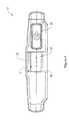
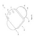
- FIG. 12is a perspective top view of another example therapeutic electrical stimulation device.
- FIG. 13is an exploded perspective view of the therapeutic electrical stimulation device shown in FIG. 12 .
- FIG. 14is a right side cross-sectional view of the device shown in FIG. 12 , including a controller that is disconnected from a patch.
- FIG. 15is a right side cross-sectional view of the device shown in FIG. 14 with the controller being arranged over the patch.
- FIG. 16is a right side cross-sectional view of the device shown in FIG. 14 with the controller being connected with the patch.
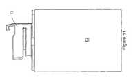
- FIG. 17is a perspective top view of the device shown in FIG. 12 in a partially assembled configuration.
- FIG. 18is a block diagram of an electrical schematic for the controller shown in FIG. 14 .
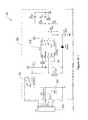
- FIG. 19is an electrical schematic of an exemplary circuit for the controller shown in FIG. 14 .
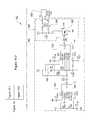
- FIG. 20is another block diagram of an electrical schematic for the controller shown in FIG. 14 .
- FIG. 21is another electrical schematic of an exemplary circuit for the controller shown in FIG. 14 .
- FIG. 22is a top perspective view of another embodiment of a patch.
- FIG. 23is a schematic illustration of possible applications and configurations for the device shown in FIG. 12 .
- FIG. 24is a perspective view of an exemplary docking station.
- FIG. 25is a block diagram of an exemplary system for communicating across a communication network including the device shown in FIG. 12 .
- device 10is a transcutaneous electrical nerve stimulation (“TENS”) device.
- Device 10includes controller 11 and shoe 13 .
- Controller 11is a device that generates electrical impulses and supplies the electrical impulses to shoe 13 .
- Shoe 13receives the electrical impulses from controller 11 and supplies the electrical impulses to a therapeutic location, such as the skin of a patient.
- controller 11includes an outer protective shell formed of upper housing 12 and lower housing 14 .
- Upper and lower housings 12 , 14are made of any suitable material such as plastic, metal, or the like.
- a lower edge of upper housing 12is configured to be connected with an upper edge of lower housing 14 .
- a fasteneris used to connect upper housing 12 to lower housing 14 .
- suitable fastenersinclude adhesive, screws, latching mechanisms, and other known fasteners.
- upper housing 12is directly connected to lower housing 14 , such as by welding or over molding.
- Upper and lower housings 12 , 14act together to enclose battery 26 and electrical circuitry 28 . As a result, upper and lower housings 12 , 14 provide protection to the enclosed components from contact with other objects that could otherwise damage the components.
- upper and lower housings 12 , 14are water resistant to protect enclosed components from water or other fluids.
- Some embodiments of upper and lower housing 12 , 14are completely sealed to resist most or all fluid, gas, or particle intrusion. Some embodiments are hermetically sealed.
- Battery 26is a power source that provides electrical power to controller 11 .
- battery 26is a rechargeable battery such as a lithium-ion battery.
- Battery 26can be charged by connecting controller 11 to a battery charger, as described further below.
- a battery chargeris a docking station described in more detail herein. Inductive charging is used in some embodiments.
- other rechargeable batteriesare used, such as a nickel cadmium battery, a nickel metal hydride battery, or a rechargeable alkaline battery.
- Yet other embodimentsinclude non-rechargeable, disposable batteries, such as alkaline batteries, or other known batteries.
- An alternate embodiment of controller 11does not include battery 26 , but rather includes a different power source such as a capacitor.
- Lower housing 14includes a controller receptacle 24 that is arranged and configured to receive a portion 42 of shoe 13 .
- lower housing 14 and portions of electrical circuitry 28are uniquely arranged and configured to mate with portion 42 and resist mating with other shoe configurations.
- a railway 28is positioned within controller receptacle 24 to receive complementary structure on show 42 .
- keyed receptacleOne benefit of a keyed receptacle is that it can be used to resist connection with inappropriate patches or other devices, such as to resist connection with a patch that would be incompatible with controller 11 .
- the keyed receptacleis also used in some embodiments to allow connection of controller 11 with various types of patches or other devices if desired.
- the electrical circuitry 28includes a PCB board 29 with a plurality of pins 31 extending therefrom. Pins 31 are sized to be received in receptacles formed in corresponding portion 42 of the shoe 13 to create an electrical connection between controller 11 and shoe 13 , as described below.
- Upper housing 12includes a member 22 that moves into and out of controller receptacle 24 to capture and release corresponding structure on the 42 of the shoe 13 .
- member 22engages structure on portion 42 to couple portion 42 to controller 11 .
- the userdepresses member 22 to disengage member 22 from portion 42 .
- Portion 42 of shoe 13can then be pulled out of controller receptacle 24 .
- controller 11includes a user interface having a power button 20 and amplitude adjustment buttons 16 and 18 .
- power button 20When power button 20 is first depressed, the controller turns ON and begins generating therapeutic electrical signals.
- power button 20When power button 20 is depressed again, the controller turns OFF and stops generating the therapeutic electrical signals.
- amplitude adjustment buttons 16 and 18are used to adjust the amplitude of the generated therapeutic electrical signals accordingly.
- Amplitude adjustment button 16provides an input to increase (“+”) the amplitude of the therapeutic electrical signals.
- Amplitude adjustment button 18provides an input to decrease (“ ⁇ ”) the amplitude of the therapeutic electrical signals.
- shoe 13is shown in greater detail.
- shoe 13includes portion 42 and a base 44 .
- a patch with an insulating layeris typically included, but not shown, and a patch with an insulating layer (see, e.g., insulating layer 122 described below).
- Portion 42is configured to engage with a receptacle (shown in FIGS. 9 and 10 ) of controller 11 .
- Portion 42is a connector used to physically and electrically connect shoe 13 with controller 11 .
- Electrodes 46 , 48extend from show 42 . Electrodes 46 , 48 are typically a sheet of electrically conductive material that, when applied to a patient, provides an electrical connection with the skin of the patient to supply electrical pulses to a desired therapeutic location.
- An adhesive layer(not show, but see adhesive layer 128 described below) is typically applied to one side of shoe 13 to allow shoe 13 to be securely, yet removably, adhered to the skin. Some embodiments of shoe 13 include additional layers.
- controller 11typically generates a voltage potential between electrodes 46 , 48 such that current enters the skin through one electrode, passes through the skin, and then returns through the other electrode. Some embodiments alternate the polarity of the electrodes during a therapy.
- a skin preparation productsuch as a conductive gel, is applied to the skin prior to application of shoe 13 .
- portion 42includes a plurality of electrical receptacles 50 on a front face 52 of portion 42 .
- Electrical receptacles 50are sized to receive pins 31 of controller 11 when portion 42 is fully inserted into connector receptacle 24 (see FIGS. 9 and 10 ). This creates an electrical connection between controller 11 and shoe 13 and allows controller 11 to deliver electrical stimulation therapy through electrodes 46 , 48 to the patient.
- Portion 42defines a channel 54 sized to receive railway 28 of controller 11 when portion 42 is inserted into controller receptacle 24 . Also, portion 42 includes a clip member 56 sized to engage a detent or lip 23 of member 22 of controller 11 when portion 42 is fully inserted into controller receptacle 24 to retain portion 42 within receptacle 24 .
- shoe 13is coupled to controller 11 .
- pins 31 of controller 11are inserted into receptacles 50 of portion 42 to create an electrical connection therebetween.
- railway 28 of controller 11is received in channel 54 of portion 42 and allows portion 42 to be slid along railway 28 as portion 42 is inserted into controller receptacle 24 .
- the engagement of railway 28 and channel 54fixes the position of controller 11 and shoe 13 in a direction Y so that shoe 13 cannot be moved out of controller receptacle 24 in the direction Y.
- lip 23 of member 22 of controller 11is engaged by clip member 56 of portion 42 .
- the engagement of lip 23 and clip member 56fixes the position of controller 11 and shoe 13 in a second dimension so that shoe 13 cannot be moved in a direction X out of controller receptacle 24 .
- the userwants to remove portion 42 from controller receptacle 24 , the user depresses member 22 in the direction Y so that lip 23 clears clip member 56 .
- Portion 42 thereuponbe slid along railway 28 in direction X out of receptacle 24 .
- a knob or knurlcan be formed on the portion 42 that engages or is seated with a detent within the receptacle when fully inserted. When the portion 42 is removed, the knob or knurl flexes slightly to bend away from the detent so that the portion can be removed.
- Other configurationsare possible.
- shoe 13is connected to a patch to deliver therapy to the user. In other examples, shoe 13 is connected to other structures to: (i) deliver therapy; (ii) charge controller 11 ; and/or (iii) program controller 11 .
- shoe 13is electrically connected to a structure 60 .
- shoe 13can be connected to a plurality of different structures so that controller 11 can be coupled thereto.
- structure 60is an apparatus that can be used to deliver therapy to the user.
- structure 60can be a patch (e.g., patch 104 ) that is attached to the skin to deliver therapy.
- structure 60is a garment such as a belt that is worn around certain anatomy of a patient, such as the waist, arm, or leg.
- One or more shoes 13can be located along the best so that one or more controllers 11 can be coupled to the shoes 13 to deliver therapy at desired locations along the belt.
- the beltcan include a single shoe 13 for one controller 11 , and can include a plurality of electrodes that are spaced along the belt to delivery therapy along an entire surface for the patient.
- structure 60is a brace or cast (e.g., air cast, knee brace, or back brace) with built-in electrodes that allow controller 11 to be connected to the shoe and delivery therapy to the desired area.
- structure 60is electrical components that are used to provide power so that controller 11 can be connected to shoe 13 to charge battery 26 in controller 11 .
- structure 60is a docking station, such as docking station 1300 described below.
- structure 60is an electrical power transformer that can be plugged into a typical wall outlet or an automobile outlet to provide power to charge battery 26 .
- controller 11can also include an auxiliary charging port, such as a USB or micro-USB port, which can be used to charge controller 11 .
- controller 11can include on-board recharge capabilities, such as solar panels or inductive coupling technologies.
- structure 60is electrical circuitry that can be used to program controller 11 .
- controller 11includes computer readable media, such as RAM or ROM.
- controller 11includes flash memory that can be rewritten with new therapy programs to enhance the functionality of controller 11 .
- structure 60can be a docking station, such as docking station 1300 described below.
- structure 60can be a component in a care giver's office that allows the care giver to modify or enhance the therapies that can be provided by controller 11 .
- Device 100is similar to device 10 described above, except that device 100 is configured differently.
- device 100is a transcutaneous electrical nerve stimulation (“TENS”) device.
- Device 100includes controller 102 and patch 104 .
- Controller 102is a device that generates electrical impulses and supplies the electrical impulses to patch 104 .
- Patch 104receives the electrical impulses from controller 102 and supplies the electrical impulses to a therapeutic location, such as the skin of a patient.
- controller 102includes a user interface having a power button 110 and amplitude adjustment buttons 112 and 114 .
- power button 110When power button 110 is first depressed, the controller turns ON and begins generating therapeutic electrical signals.
- power button 110When power button 110 is depressed again, the controller turns OFF and stops generating the therapeutic electrical signals.
- amplitude adjustment buttons 112 and 114are used to adjust the amplitude of the generated therapeutic electrical signals accordingly.
- Amplitude adjustment button 112provides an input to increase the amplitude of the therapeutic electrical signals.
- Amplitude adjustment button 114provides an input to decrease the amplitude of the therapeutic electrical signals.
- Patch 104is typically applied to the skin of a patient. The electrical signals are conducted from the controller to the skin by patch 104 .
- Patch 104includes a shoe 120 (shown in FIG. 13 ), an insulating layer 122 , and conductive electrodes 124 and 126 .
- Shoe 120is connected to one side of insulating layer 122 , and is configured to engage with a receptacle (shown in FIG. 14 ) of controller 102 .
- Shoe 120is a connector used to physically and electrically connect patch 104 with controller 102 .
- Electrodes 124 and 126are located adjacent insulating layer 122 on a side opposite shoe 120 .
- the electrodesare typically a sheet of electrically conductive material that, when applied to a patient, provides an electrical connection with the skin of the patient to supply electrical pulses to a desired therapeutic location.
- An adhesive layer 128is typically applied to one side of patch 104 to allow patch 104 to be securely, yet removably, adhered to the skin.
- Some embodiments of patch 104include additional layers.
- controller 102typically generates a voltage potential between electrodes 124 and 126 such that current enters the skin through one electrode, passes through the skin, and then returns through the other electrode. Some embodiments alternate the polarity of the electrodes during a therapy.
- a skin preparation productsuch as a conductive gel, is applied to the skin prior to application of patch 104 .
- buttons 110 , 112 , and 114are arranged with a unique tactile arrangement.
- buttons 110 , 112 , and 114are arranged at one end of controller 102 and protrude out from the housing of controller 102 .
- the tactile arrangementallows the device to be controlled by the patient or caregiver even if the device is hidden from view under clothing or in a non-visible location, such as on the back. If, for example, the device is located under a shirt on the patient's upper arm, the patient can feel controller 102 through the shirt and locate protruding buttons 110 , 112 , and 114 . Due to the unique arrangement of buttons 110 , 112 , and 114 , the user is able to identify each button, and select from them accordingly.
- buttons 110 , 112 , and 114include an elevated identifier, such as a line, square, arrow, dot, circle, or Braille character.
- buttons 110 , 112 , and 114each include a unique shape, such as a square, triangle, circle, oval, rectangle, arrow, or other desired shape.
- buttonsare located on different locations of the housing, such as on the sides or bottom of the housing.
- FIG. 13is an exploded perspective view exemplary therapeutic electrical stimulation device 100 .
- Device 100includes controller 102 and patch 104 .
- Controller 102includes upper housing 202 , battery 204 , user input devices 206 , electrical circuitry 208 , and lower housing 210 .
- Patch 104includes shoe 120 , insulating layer 212 , electrodes 124 and 126 , and adhesive layer 128 .
- Controller 102includes an outer protective shell formed of upper housing 202 and lower housing 210 .
- Upper and lower housings 202 and 210are made of any suitable material such as plastic, metal, or the like.
- a lower edge of upper housing 202is configured to be connected with an upper edge of lower housing 210 .
- a fasteneris used to connect upper housing 202 to lower housing 210 . Examples of suitable fasteners include adhesive, screws, latching mechanisms, and other known fasteners.
- upper housing 202is directly connected to lower housing 210 , such as by welding or over molding.
- Upper and lower housings 202 and 210act together to enclose battery 204 and electrical circuitry 208 and to at least partially enclose user input devices 206 . As a result, upper and lower housings 202 and 210 provide protection to the enclosed components from contact with other objects that could otherwise damage the components. In some embodiments, upper and lower housings 202 and 210 are water resistant to protect enclosed components from water or other fluids. Some embodiments of upper and lower housing 202 and 210 are completely sealed to resist most or all fluid, gas, or particle intrusion. Some embodiments are hermetically sealed.
- Lower housing 210includes a controller receptacle 211 that is arranged and configured to receive shoe 120 of patch 104 .
- lower housing 210 and portions of electrical circuitry 208are uniquely arranged and configured to mate with shoe 120 and resist mating with other shoe configurations. This is sometimes referred to as a keyed receptacle.
- a keyed receptacleOne benefit of a keyed receptacle is that it can be used to resist connection with inappropriate patches or other devices, such as to resist connection with a patch that would be incompatible with controller 102 .
- the keyed receptacleis also used in some embodiments to allow connection of controller 102 with various types of patches or other devices if desired.
- Battery 204is a power source that provides electrical power to controller 102 .
- battery 204is a rechargeable battery such as a lithium-ion battery.
- Battery 204can be charged by connecting controller 102 to a battery charger.
- a battery chargeris a docking station described in more detail herein. Inductive charging is used in some embodiments.
- other rechargeable batteriesare used, such as a nickel cadmium battery, a nickel metal hydride battery, or a rechargeable alkaline battery.
- Yet other embodimentsinclude non-rechargeable, disposable batteries, such as alkaline batteries, or other known batteries.
- An alternate embodiment of controller 102does not include battery 204 , but rather includes a different power source such as a capacitor.
- User input devices 206receive input from a user to cause controller 102 to adjust an operational mode of the device 100 .
- User input devices 206include power button 110 and amplitude adjustment buttons 112 and 114 .
- User input devices 206are arranged such that a portion of buttons 110 , 112 , and 114 protrude through upper housing 202 .
- a userprovides input to controller 102 by momentarily depressing one of buttons 110 , 112 , and 114 .
- the buttonWhen the button is depressed, the force is transferred through user input device 206 to a switch of electrical circuitry 208 .
- the switchcloses to make an electrical connection and causes current flow within electrical circuitry 208 .
- the electrical circuitry 208responds to adjust the appropriate operational mode of controller 102 .
- Electrical circuitry 208typically includes a circuit board and a plurality of electrical circuits such as a power supply circuit, pulse generator circuit, and electrical contacts for electrical connection with conductors of shoe 120 . Examples of electrical circuitry 208 are described in more detail herein.
- electrical circuitry 208includes sensors that receive electrical signals from patch 104 . In some embodiments the electrical circuitry is activated between output pulses to monitor the patient. Some embodiments of controller 102 further include sensor electronics that monitor patch 104 to be sure that patch has not become partially or fully disconnected from the patient. If the patch does become disconnected, the electronics deactivate delivery of therapeutic electrical signals from controller 102 . In some embodiments, the electronics monitor for changes in impedance between electrodes. In another embodiment, electrical circuitry 208 also includes activity monitoring, such as with an accelerometer.
- Patch 104is a device that transfers electrical impulses from controller 102 to a therapeutic location on a patient, such as the patient's skin.
- Patch 104includes shoe 120 , insulating layer 212 , electrodes 124 and 126 , and adhesive layer 128 .
- Shoe 120is arranged and configured to engage with controller 102 , such as through controller receptacle 211 .
- shoe 120includes a unique configuration that is designed to mate only with controller receptacle 211 and to resist connection with other receptacles or devices. This is sometimes referred to as a keyed shoe.
- One benefit of a keyed shoeis that it can be used to resist connection with inappropriate controllers or other devices, such as to resist connection with a controller that would be incompatible with patch 104 .
- the keyed shoeis also used in some embodiments to allow patch 104 to be connected with various types of controller 102 .
- Shoe 120includes conductors that conduct electrical signals between controller 102 and electrodes 124 and 126 .
- Patch 104includes insulating layer 212 .
- Insulating layer 212is connected to patch 104 by any suitable fastening mechanism, such as adhesive, screws, nails, or other known fasteners.
- insulating layer 212 and shoe 120are formed of a unitary piece, such as by molding. Conductors from shoe 120 pass from shoe 120 , through insulating layer 212 , and are connected to electrodes 124 and 126 .
- insulating layer 212is a primary structural layer of patch 104 . Insulating layer 212 also electrically insulates a side of patch 104 . In this way, if insulating layer 212 comes into contact with a conductive object (e.g., the hand of the patient or another electronic device), insulating layer 212 prevents or at least resists the electrical conduction between electrodes 124 and 126 and the conductive object. Inadvertent electrical shocks and unintended electrical connections are thereby reduced or entirely prevented.
- a conductive objecte.g., the hand of the patient or another electronic device
- Electrodes 124 and 126are electrical conductors that are used to introduce electrical signals to a therapeutic location of a patient, such as on to the patient's skin. Electrodes 124 and 126 are electrically connected to conductors that pass through shoe 120 . In some embodiments electrodes 124 and 126 are generally disk-shaped to distribute the electrical signals across a relatively large area of skin. In other embodiments, electrodes 124 and 126 are of a variety of other shapes including ring-shaped, circular, elliptical, serpentine, comb-shaped, or other desired shape.
- Patch 104is connected to the skin of a patient with adhesive layer 128 .
- adhesive layer 128is applied across an entire surface of patch 104 , including across electrodes 124 and 126 .
- adhesive layer 128is electrically conductive.
- adhesive layer 128is applied to the surface of patch 104 , but not on the regions of electrodes 124 and 126 .
- Other adhesive layer arrangementsare used in other embodiments.
- FIGS. 14-16illustrate an exemplary method of connecting a controller 102 to a patch 104 of a therapeutic electrical stimulation device 100 .
- FIGS. 14-16are right side cross-sectional views of device 100 .
- FIG. 14illustrates controller 102 disconnected from patch 104 .
- FIG. 15illustrates controller 102 arranged in a first position over patch 104 .
- FIG. 16illustrates controller 102 arranged in a second position and connected with patch 104 .
- a method of disconnecting controller 102 from patch 104is the reverse of that described herein.
- patch 104is typically applied to a desired therapeutic location on the patient (not shown in FIG. 14 ) such that shoe 120 extends from patch 104 in a direction generally away from the therapeutic location.
- controller 102begins as illustrated in FIG. 14 , such that controller 102 is arranged such that controller receptacle 211 is in line with shoe 120 . Controller 102 is also oriented such that rear side 301 of shoe 120 is facing toward the rear side 302 of receptacle 211 .
- shoe 120 in receptacle 211is shaped such that shoe 120 can only be inserted into receptacle 211 in a single orientation. In other embodiments, shoe 120 can be inserted within receptacle 211 in multiple orientations, but can only be fully engaged (as shown in FIG. 16 ) if shoe 120 and receptacle 211 are properly oriented.
- controller 102is moved toward patch 104 in the direction of arrow A 1 , such that shoe 120 enters receptacle 211 as shown in FIG. 15 . Controller 102 is then advanced in the direction of arrow A 2 . This movement of controller 102 causes shoe 120 to engage with controller 102 as shown in FIG. 16 .
- electrical circuitry 208makes electrical contact with conductors of shoe 120 to electrically connect electrodes of patch 104 with electrical circuitry 208 .
- Electrical connectorsare used to electrically connect conductors of shoe 120 with electrical circuitry 208 .
- male and female plug-type connectorsare included as part of shoe 120 and electrical circuitry 208 .
- surface conductorsare used to connect with protruding electrical contacts, such as used in Universal Serial Bus (USB) connectors and for connecting memory cards with memory slots.
- USBUniversal Serial Bus
- Other electrical connectorsare used in other embodiments.
- FIGS. 14-16illustrate a two-step method of connecting patch 104 and controller 102 .
- the first stepinvolves moving controller 102 in the direction of arrow A 1
- the second stepinvolves moving controller 102 in the direction of arrow A 2 .
- This method of connectionis partially a result of the “L-shape” of shoe 120 .
- Shoe 120has a first portion 304 that extends generally normal to a surface of insulating layer 212 , and a second portion 306 that extends at generally a right-angle to the first portion 304 .
- shoe 120resists unintentional disengagement of controller 102 from patch 104 , once controller 102 is properly connected (as shown in FIG. 16 ). For example, if a force is applied to controller 102 in a direction opposite arrow A 1 , the second portion of shoe 120 resists disengagement of controller 102 from patch 104 . Sideways forces (e.g., forces normal to arrow A 1 and arrow A 2 ) are also resisted, as well as a force in the direction of arrow A 2 . A force in the direction opposite arrow A 2 will result in disconnection of shoe 120 from electrical circuitry 208 .
- Sideways forcese.g., forces normal to arrow A 1 and arrow A 2
- a force in the direction opposite arrow A 2will result in disconnection of shoe 120 from electrical circuitry 208 .
- shoe 120will still provide support to receptacle 211 unless controller 102 is arranged vertically below patch 104 . This allows the user to manually grasp controller 102 before it becomes completely disconnected from patch 120 and reconnect controller 102 , if desired. If controller 102 is arranged vertically below patch 104 , then gravity will tend to pull controller 102 away from patch 104 .
- shoe 120has a generally linear shape (not shown in FIGS. 14-16 ), such that shoe 120 is plugged directly into controller 102 in a single step, namely the insertion of shoe 120 into receptacle 211 .
- electrical circuitry 208includes an electrical connector that is in line with the path of entry of shoe 120 into receptacle 211 or directly surrounds the point of entry.
- shoe 120has an “L-shape” but receptacle 211 is arranged on a side of controller 102 .
- connection of controller 102 with patch 104is accomplished in a single step—insertion of a second portion of shoe 104 into the side receptacle.
- shoe 120 and receptacle 211are arranged and configured to safely disconnect from each other upon the application of a sufficient force. If the user bumps device 100 on another object, for example, it is preferred that controller 102 electrically disconnects from patch 104 before patch 104 becomes disengaged from the patient. Shoe 120 and receptacle 211 are designed to remain connected unless a sufficient force is applied to controller 102 and before the force becomes large enough to disconnect patch 104 from the patient.
- FIG. 17is a perspective top view of an exemplary embodiment of partially assembled device 100 .
- Device 100includes controller 102 and patch 104 .
- Controller 102includes user input device 206 and electrical circuitry 208 .
- Electrical circuitry 208includes circuit board 602 and electronic components 604 .
- Electrical components 604include transformer 606 , status indicator 608 , and electrical connector 610 .
- shoe 120is shown in the fully connected position, such as shown in FIG. 16 .
- electrical connectors of shoe 120mate with electrical connectors 610 of electrical circuitry 208 .
- Circuit board traces on or within circuit board 602communicate electrical signals between electrical components 604 and shoe 120 .
- transformer 606Some embodiments of electrical circuitry 208 include transformer 606 .
- the transformeris mounted on a surface of the circuit board.
- some embodimentsinclude a hole in circuit board 602 . Transformer 606 is inserted within the hole to reduce the overall distance that transformer 606 extends above circuit board 602 . This allows upper and lower housing 202 and 210 to have a reduced profile.
- Some embodimentsinclude one or more status indicators 608 .
- Status indicatorsinform a user of the operational status of device 100 and can come in the form of visual, audible, and/or tactile indicators. Examples of suitable status indicators 608 include a light, an LED, a liquid crystal or other type of display, a speaker, a buzzer, and a vibrator. Status indicators 608 are used in some embodiments to show whether device 100 is ON or OFF. In other embodiments, status indicators 608 communicate an operational mode, such as a type of therapy being provided, or a change in operational mode, such as an increase or decrease in amplitude.
- status indicators 608are used to show battery power status (e.g., full power, percentage of full power, or low on power/in need of charge), or charging status (e.g., charging or fully charged). Other indicators are used in other possible embodiments. Speakers, buzzers, and vibrators are particularly useful for those with certain disabilities or impairments and also for communication when the device is located in an area that is not easily visible (e.g., on the back of a patient).
- FIG. 18is a block diagram of an exemplary electrical schematic for controller 102 .
- Controller 102includes power supply 700 , pulse generator 702 , power switch 704 , amplitude adjustment switches 706 , and output 708 .
- Power supply 700provides electrical power to controller 102 .
- power supply 700includes a battery and also includes power filtering and/or voltage adjustment circuitry.
- Power supply 700is electrically coupled to power switch 704 and to pulse generator 702 .
- Power switch 704receives input from a user through power button 110 (e.g., shown in FIG. 12 ) and operates with power supply 700 to turn controller 102 ON or OFF.
- Pulse generator 702generates therapeutic electrical signals. Pulse generator 702 is electrically coupled to output 708 and provides the electrical signals to output 708 . In turn, output 708 is electrically coupled to patch electrodes to deliver the electrical signals to the therapeutic location of the patient. Amplitude adjustment switches 706 are electrically coupled to pulse generator 702 and receive input from the user through amplitude adjustment buttons 112 and 114 (e.g., shown in FIG. 12 ). Amplitude adjustment switches 706 operate with pulse generator 702 to adjust the intensity of the electrical signals sent to output 708 .
- pulse generator 702are simple modulated pulse (SMP) signals. Other configurations and electrical signals are possible.
- SMPsimple modulated pulse
- FIG. 19is an electrical schematic of an exemplary circuit for controller 102 .
- Controller 102includes power supply 800 , pulse generator 802 , power switch 804 , amplitude adjustment switch 806 , and output 808 .
- Power supply 800includes battery 812 , thermistor 814 , step up converter 816 , and other electrical components.
- Power supply 800is electrically coupled to supply power to pulse generator 802 .
- power supply 804is electrically coupled to connector block 820 that is used to supply power to power supply 800 to charge battery 812 .
- battery 812is a lithium-ion battery having a voltage of about 3.7 to 4.2 volts, although other battery types and voltages are used in other embodiments.
- Thermistor 814is electrically coupled between battery 812 and connector block 820 and is used to detect the temperature of battery 812 to ensure that battery 812 is not overheated while recharging.
- Power switch 804is used to turn controller 102 ON or OFF. In one embodiment, switch 804 is a single pole double throw (SPDT) switch, as shown.
- Power supply 800also includes step up converter 816 . Step up converter 816 operates to increase the voltage of power from battery 812 to a desired voltage.
- One suitable step up converteris the LTC3401 micropower synchronous boost converter that is distributed by Linear Technology Corporation, with headquarters in Milpitas, Calif.
- Pulse generator 802receives power from power supply 700 and generates a therapeutic electrical signal.
- the therapeutic electrical signalis provided to by pulse generator 802 to output 808 .
- Pulse generator 802includes amplitude adjustment switch 806 .
- amplitude adjustment switch 806is a potentiometer. When the potentiometer is adjusted, intensity of the electrical signal generated by pulse generator 802 is increased or decreased accordingly.
- pulse generator 802includes first and second timers 830 and 832 as well as additional circuitry as shown.
- both timers 830 and 832are the TS556 low-power dual CMOS timer, distributed by STMicroelectronics, with headquarters in Geneva, Switzerland.
- Pulse generator 802also includes output stage 840 .
- Output stage 840includes MOSFET 842 and transformer 844 .
- Output stage 840acts to increase the output voltage of the electrical signal before sending the electrical signal to output 808 .
- FIG. 20is a block diagram of another exemplary electrical schematic for controller 102 .
- controller 102is formed from primarily digital circuitry.
- Controller 102includes power supply 902 , battery 904 , controller processor 906 , power switch 108 , amplitude adjustment switches 910 , data communication device 912 , data storage device 914 , output stage 916 , and output 918 .
- Controller 102can be connected to external power source 920 , such as to charge battery 904 .
- external power source 920is a home or commercial power supply, such as available through an electrical power outlet.
- external power source 920is an vehicle power supply, such as accessible through a 12V receptacle.
- power supply 902receives power from battery 904 .
- Power supply 902converts the battery power to a desired voltage before supplying the power to other components of controller 102 .
- Power supply 902also includes battery charger 930 .
- Battery charger 930receives power from an external power supply and operates to recharge battery 904 .
- Control processor 906controls the operation of controller 102 .
- Control processor 906is powered by power supply 902 .
- Control processor 906also generates electrical signals that are provided to output stage 916 .
- Control processor 906is electrically coupled to power switch 908 and amplitude adjustment switches 910 .
- Control processor 906monitors the state of power switch 908 . When control processor 906 detects that the state of power switch 908 has changed, control processor 906 turns controller 102 ON or OFF accordingly. Control processor 906 also monitors the state of amplitude adjustment switches 910 . When control processor 906 detects that the state of amplitude adjustment switches 910 has changed, control processor 906 increases or decreases the intensity of electrical signals provided to output stage 916 accordingly.
- Control processor 906includes memory 932 .
- Firmware 934is stored in memory 932 .
- Firmware 934includes software commands that are executed by control processor 906 and defines logical operations performed by control processor 906 .
- controller 102includes a data communication device 912 .
- Data communication devicesinclude wired or wireless communication devices, such as serial bus communication devices (e.g., a Universal Serial Bus communication devices), local area networking communication devices (e.g., an Ethernet communication device), a modem, a wireless area networking communication device (e.g., an 802.11x communication device), a wireless personal area networking device (e.g., a BluetoothTM communication device), or other communication device.
- Data communication device 912can be used to send and receive data with another device.
- data communication device 912can be used to download different firmware 934 to alter the operation of control processor 906 .
- Data communication device 912can also be used to upload data to another device.
- control processor 906stores a therapy log in data storage device 914 .
- the control processor 906can be used to upload the therapy log to an external device by sending the data log to data communication device 912 .
- Data storage deviceis a device capable of storing data, such as a memory card or other known data storage device.
- data storage device 914is part of memory 932 .
- control processor 906When controller 102 is ON, control processor 906 generates therapeutic electrical signals, and provides those signals to output stage 916 .
- Output stage 916converts and filters the electrical signals, and then provides the electrical signals to output 918 .
- Output 918is electrically coupled to a patch that delivers electrical signals to the patient.
- FIG. 21is an electrical schematic of another exemplary circuit for controller 102 .
- controller 102includes a control processor 1006 that controls the operation of controller 102 .
- controller 102is made from primarily digital circuitry.
- Controller 102includes power supply 1002 , battery 1004 , control processor 1006 , power switch 1008 , amplitude adjustment switches 1010 , output stage 1016 , and output 1018 .
- Controller 102can also be connected to external power source 1020 , such as to charge battery 1004 .
- power supply 1002includes a lithium-ion charge management controller 1030 and a step up converter 1032 , as well as other electrical components as shown.
- a lithium-ion charge management controller 1030is the MCP73833 stand-alone linear lithium-ion charge management controller manufactured by Microchip Technology Inc., of Chandler, Ariz.
- An example of a suitable step up converteris the LTC3401 micropower synchronous boost converter.
- Battery 1004provides power to power supply 1002 .
- battery 1004is a lithium-ion 3.7V battery.
- Power supply 1002can also be connected to external power source 1020 , such as a 5V DC power source.
- External power source 1020provides power to power supply 1002 that enables power supply 1002 to recharge battery 1004 .
- battery 1004includes a thermistor to monitor the temperature of battery 1004 during charging.
- Control processor 1006controls the operation of controller 102 .
- a suitable control processor 1006is the ATtiny44 8-bit microcontroller manufactured by Amtel Corporation, located in San Jose, Calif.
- various other processing devicesmay also be used including other microprocessors, central processing units (CPUs), microcontrollers, programmable logic devices, field programmable gate arrays, digital signal processing (DSP) devices, and the like.
- Control processor 1006may be of any general variety such as reduced instruction set computing (RISC) devices, complex instruction set computing devices (CISC), or specially designed processing devices such as an application-specific integrated circuit (ASIC) device.
- RISCreduced instruction set computing
- CISCcomplex instruction set computing devices
- ASICapplication-specific integrated circuit
- Control processor 1006is electrically coupled to power switch 1008 and amplitude adjustment switches 1010 .
- Power switch 1008provides signals to control processor 1006 that cause control processor 1006 to alternate controller 102 between ON and OFF states accordingly.
- Amplitude adjustment switches 1010instruct control processor 1006 to adjust the intensity of the electrical signals generated by controller 102 .
- Electrical signals generated by control processor 1006are passed to output stage 1016 .
- Output stage 1016converts the electrical signals received from control processor 1006 to an appropriate form and then provides the electrical signals to output 1018 .
- output stage 1016includes MOSFET 1042 and transformer 1044 .
- Other embodimentsdo not include transformer 1044 , but rather use a flyback converter or other converter to generate an appropriate output signal.
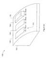
- FIG. 22is a top perspective view of another exemplary embodiment of patch 104 .
- Patch 104includes insulating layer 212 and shoe 120 .
- Shoe 120is connected to a surface of insulating layer 212 .
- shoe 120includes wires 1101 and 1103 that are electrically coupled to conductors within shoe 120 .
- Wires 1101 and 1103are also connected at an opposite end to patches 1102 and 1104 .
- patch 104includes one or more electrodes, such as shown in FIG. 13 , and an adhesive layer that allows patch 104 to be connected to a patient or other device.
- patch 104does not include an electrode, but rather passes electrical signals through wires 1101 and 1103 to patches 1102 and 1104 .
- Patches 1102 and 1104include one or more electrodes and can be adhered to the patient such as with an adhesive layer. The electrodes of patches 1102 and 1104 direct the electrical signals to desired therapeutic locations of the patient.
- Shoe 120includes an appropriate number of electrical conductors that can provide multiple electrical conduction channels for communicating electrical signals between controller 102 (such as shown in FIG. 12 ) and the patches.
- wires 1101 and 1103are formed adjacent to or within insulating layers to provide additional protection to the wires from damage.
- wires 1101 and 1103are other types of electrical conductors.
- multiple electrode sitescan be positioned in a patch 104 .
- a quad-patchcan be formed with an insulating layer have four lobes, with each lob having an electrode for delivery of therapy. Other configurations are possible.
- patches 104 , 1102 , and 1104do not include an adhesive layer, but rather are held in place by a band, strap, brace, built, garment, active wear, or other suitable supporting object.
- patchescan be formed integral with a supporting object or inserted within a pocket or recess of a supporting object.
- Some embodimentsinclude integrated hot or cold packs.
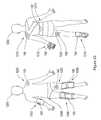
- FIG. 12schematically illustrates some of the possible applications and configurations of therapeutic electrical stimulation device 100 .
- FIG. 23illustrates a patient 1200 including a front profile (left) and a rear profile (right).
- device 100is to reduce joint pain or to reduce swelling in a joint.
- device 100is integrated into elbow brace 1202 , hip support 1204 , knee braces 1206 and 1208 , shoulder brace 1210 , glove 1212 , back support 1214 , and sock 1216 to provide relief from pain or swelling at the respective location.
- device 100can be used to treat symptoms at the patient's elbow, hip, knee, shoulder, wrist, hand, fingers, back, ankle, foot, or any other joint in the body.
- embodiments of device 100are directly adhered to the desired therapeutic location, such as shoulder 1220 , as described herein.
- device 100Another application of device 100 is to reduce muscle or other tissue pain at any desired therapeutic location on the body. For example, device 100 is adhered to thigh 1222 of patient 1200 .
- device 100can be placed on or adjacent to wound 1224 (shown on the rear left thigh of patient 1200 ). Some embodiments of device 100 act as electronic adhesive bandage to promote wound healing and reduce pain associated with wound 1224 . Some embodiments of device 100 include controller 102 and patch 104 (such as shown in FIG. 12 ) as a single non-separable unit.
- alternate patch configurationscan be used to supply therapeutic electrical signals to multiple locations of the body (e.g., a back and hip) or to multiple regions of the same body part (e.g., opposite sides of the knee or top and bottom of the foot).
- multiple devices 100are in data communication with each other to synchronize therapies provided by each respective device.
- wireless communication devicese.g., 912 shown in FIG. 20
- device 100is configured to provide interferential therapy, such as to treat pain originating within tissues deeper within the body than a typical TENS device.
- Some embodiments of device 100are configured for drug delivery. Such embodiments typically include a drug reservoir (such as absorbent pads) within patch 104 (e.g., shown in FIG. 13 ). Iontophoresis is then used to propel the drug (such as medication or bioactive-agents) transdermally by repulsive electromotive forces generated by controller 102 .
- a drug reservoirsuch as absorbent pads
- Iontophoresisis then used to propel the drug (such as medication or bioactive-agents) transdermally by repulsive electromotive forces generated by controller 102 .
- An example of a suitable device for iontophoresisis described in U.S. Pat. No. 6,167,302 by Philippe Millot, titled DEVICE FOR TRANSCUTANEOUS ADMINISTRATION OF MEDICATIONS USING IONTOPHORESIS, the disclosure of which is hereby incorporated by reference in its entirety.
- controller 100can be programmed to deliver microcurrent.
- microcurrentcan be a constant voltage that is delivered for wound healing purposes.
- Other therapiescan be delivered to address pain, edema, drop-foot, and other abnormalities.
- FIG. 24is a perspective view of an exemplary docking station 1300 .
- Docking station 1300includes housing 1302 including multiple slots 1304 , 1306 , and 1308 and status indicators 1310 associated with each slot.
- Each slot of the docking station 1300is arranged and configured to receive a controller 102 of a therapeutic electrical stimulation device 100 , such that multiple controllers 102 can be connected with docking station 1300 at any time.
- some embodiments of docking station 1300include only a single slot 1304 or other port for connection to a single controller 102 .
- Other embodimentsinclude any number of slots as desired.
- Docking station 1300includes an electrical connector similar to shoe 120 , such as shown in FIGS. 3-5 .
- shoe 120engages with receptacle 211 , such as shown in FIGS. 14-16 .
- docking station 1300is electrically coupled to controller 102 .
- docking station 1300performs two primary functions.
- the first function of docking station 1300is to recharge the battery of controller 102 .
- docking station 1300is typically electrically coupled to a power source such as an electrical wall outlet.
- Docking station 1300converts the power from the electrical wall outlet to an appropriate form and then provides the power to the power supply (e.g., 902 shown in FIG. 20 ) of controller 102 .
- the second function of docking station 1300is to communicate data between controller 102 and a communication network. Controller 102 can send to docking station 1300 and can receive data from docking station 1300 . This function is described in more detail with reference to FIG. 25 .
- docking station 1300provides only one of these functions. Other embodiments provide additional features and functionality. For example, some embodiments of docking station 1300 allow multiple devices 100 to communicate with each other when connected with docking station 1300 . In other examples, docking station 1300 is also configured to communicate with one or more computers accessible through a network, as described below.
- Docking station 1300includes status indicators 1310 associated with each slot of docking station 1300 .
- status indicators 1310include a data communication indicator and a charging indicator.
- the data communication indicatoris a light emitting diode (LED) that illuminates when the docking station 1300 is communicating with the respective controller 102 .
- the charging indicatoris an LED that illuminates when docking station 1300 is charging the respective controller 102 .
- Other embodimentsinclude additional status indicators 1310 .
- Other types of status indicatorsinclude audible status indicators (e.g., speakers, buzzers, alarms, and the like) and visible status indicators (e.g., lights, liquid crystal displays, display screens, and the like).
- Docking station 1300is not limited to connection with a single type of controller 102 . Multiple types of controllers 102 can be connected with docking station 1300 at any one time, if desired.
- controllers 102include a TENS device, an iontophoresis device, a muscle stimulation device (e.g., a neuromuscular electrical stimulation (NMES) device), a wound healing device, an interferential device, or other devices.
- NMESneuromuscular electrical stimulation
- docking station 1300is configured to be used at a patient's home, such as in a bathroom or kitchen. Docking station 1300 can include multiple stations for charging different types of devices, as well as drawers and other conveniences that allow docking station 1300 to be used for multiple purposes.
- FIG. 25is a block diagram of an exemplary system for communicating across communication network 1400 involving therapeutic electrical stimulation devices.
- the systemincludes devices 102 , 1402 , and 1404 .
- Devices 102are in data communication with docking station 1300 , such as shown in FIG. 24 .
- Device 1402includes a wireless communication device and device 1404 includes a wired network communication device.
- the systemalso includes server 1406 , caregiver computing system 1408 , and patient computing system 1410 .
- Server 1406includes database 1412 and Web server 1414 .
- Systemalso includes wireless router 1416 .
- Communication network 1400is a data communication network that communicates data signals between devices.
- communication network 1400is in data communication with docking station 1300 , device 1402 , device 1404 , server 1406 , caregiver computing system 1408 , patient computing system 1410 , and wireless router 1416 .
- Docking station 1300is in data communication with devices 102 .
- Wireless router 1416is in data communication with device 1404 .
- Examples of communication network 1400include the Internet, a local area network, an intranet, and other communication networks.
- devices 102 , 1402 , and 1404store, in memory, data relating to therapy delivery or other operational characteristics of the respective devices.
- Communication network 1400can be used to communicate that data to another device. For example, the data is transferred to patient computing system 1410 or to caregiver computing system 1408 . Once the data has been transferred to the computing system, the data is stored for review and analysis by the patient or the caregiver.
- Communication network 1400can also be used to communicate data from devices 102 , 1402 , and 1404 to server 1406 .
- Server 1406stores the data in patient record 1420 .
- server 1406includes Web server 1414 .
- Web server 1414includes caregiver interface 1430 patient interface 1432 . Additional interfaces are provided in some embodiments to third parties, such as an insurance company.
- Web server 1414generates web pages that are communicated across communication network 1400 using a standard communication protocol.
- An example of such a protocolis hypertext transfer protocol.
- the webpage datais arranged in a standard form, such as hypertext markup language.
- the webpage datais transferred across communication network 1400 and received by computing system 1408 and computing system 1410 .
- a browser operating on respective computing systemreads the webpage data and displays the webpage to the user.
- Caregiver interface 1430generates a webpage intended for use by a caregiver.
- the caregiver interface 1430allows the caregiver to access patient records 1420 and generates reports or graphs to assist the caregiver in analyzing data from patient records 1420 .
- caregiver interface 1430provides technical or medical suggestions to the caregiver.
- caregiver interface 1430also allows the caregiver to request adjustments to an operational mode of a device 102 , 1402 , or 1404 . The operational mode adjustments are then communicated from server 1406 to the device, and the device makes the appropriate mode adjustments.
- Patient interface 1432generates a webpage intended for use by a patient.
- patient interface 1432allows the patient to access patient records 1420 and generates reports or graphs that assist the patient in analyzing data from patient records 1420 .
- Patient interface 1432provides instructions to assist the patient with uploading data from device 102 , 1402 , or 1404 to patient records 1420 . Instructions or other educational information is also provided by patient interface 1432 , if desired.
- database 1412includes firmware repository 1422 .
- Firmware repository 1422includes data instructions that define the logical operation of a controller 102 (e.g. firmware 934 shown in FIG. 20 ).
- Firmware repository 1422is used in some embodiments to store various versions of firmware. For example, when a new firmware version is created, the developer stores the new version of firmware in the firmware repository 1422 . The firmware is then communicated to the appropriate devices 102 , 1402 , or 1404 . The communication of new firmware versions can be either automatically distributed, or provided as an option to a patient or caregiver through interfaces 1430 and 1432 . In some embodiments, patient interface 1432 requires that a patient agree to pay for an upgraded firmware version before the firmware is made available for installation on a device.
- firmware repository 1422includes different firmware algorithms. Each firmware algorithm is specifically tailored to provide a specific therapy when executed by devices 102 , 1402 , 1404 or to be used with a particular hardware configuration. Examples of therapies defined by separate firmware algorithms include TENS, interferential therapy, edema therapy, muscle stimulation, iontophoresis therapy, and other therapies. A different firmware algorithm can also be specifically tailored for particular hardware configurations, such as for particular electrode numbers or configurations, for particular data communication devices, for different docking stations, or to accommodate other differences in hardware configuration.
- a patientmay first obtain a TENS device including a patch shown in FIG. 12 .
- the deviceincludes a first firmware type that defines an algorithm appropriate for TENS therapy.
- the patientdesires to upgrade the device to cause the device to operate as an iontophoresis device.
- the patientuses patient computing system 1410 to access patient interface 1432 .
- the patientselects a new firmware algorithm that is designed for iontophoresis therapy.
- the patientpurchases and downloads the firmware associated with the iontophoresis therapy and loads the firmware onto the device.
- an appropriate patchcan be purchased through patient interface 1432 and delivered to the patient.
- the patchis then connected to the device controller and the new firmware algorithm is executed.
- the firmwarecauses the device to provide the desired iontophoresis therapy.
- some embodiments of controller 102are customizable to provide multiple different therapies.
- firmwareis specially tailored for providing a therapy to a particular part of the body.
- separate firmware algorithmsare available for the treatment of separate body parts and conditions associated with those body parts. Such firmware algorithms can be obtained by downloaded, as described above.
- controllers 11 , 100include graphical user interfaces that allow the user to control the controllers 11 , 100 and the therapy provided thereby.
- the controllerscan include built-in displays that are used to present the user interfaces.
- the user interfaceshave home pages that allow the user to control various aspects of the controller, such as turning the device on and off, the type of therapy provided, and the intensity of the therapy.
- a separate deviceis used to control the controllers 11 , 100 .
- This devicecan communicate with the controllers 11 , 100 through wired or wireless means (e.g., Wifi, Bluetooth).
- a docking statione.g., docking station 1300 described above
- the docking stationcan communicate wirelessly with controllers 11 , 100 .
- controllers 11 , 100can include additional functionality, such as open lead detection. If a lead looses contact with a surface that is being delivered therapy, controllers 11 , 100 are programmed to detect the open lead and to modify therapy appropriately until the lead again makes contact. For example, controllers 11 , 100 can be programmed to shut down therapy that is delivered to the open lead and to issue an alarm so that the user can replace the lead.
- additional functionalitysuch as open lead detection. If a lead looses contact with a surface that is being delivered therapy, controllers 11 , 100 are programmed to detect the open lead and to modify therapy appropriately until the lead again makes contact. For example, controllers 11 , 100 can be programmed to shut down therapy that is delivered to the open lead and to issue an alarm so that the user can replace the lead.
- controllers 11 , 100are programmed to sense feedback from the user and modify therapy accordingly.
- controllers 11 , 100can be programmed to sense electromyographic biofeedback based on muscle activity and regulate therapy accordingly.
- controllers 11 , 100are programmed to sense impedance and deliver therapy accordingly.
- other biofeedbacksuch as heart rate or activity levels can also be monitored. Other configurations are possible.
- the usercan provide specific feedback as well.
- the usercan set pain thresholds that controllers 11 , 100 are programmed to remember.
- the pain thresholdscan be set automatically by controllers 11 , 100 by monitoring capacitance levels.
- controllers 11 , 100can include accelerometers and/or gyroscopes that can be used to measure orientation and activity level of the patient. For example, therapy can be adjusted based on the orientation of the patient (e.g., lying down or upright), as well as activity level. Controllers 11 , 100 can be programmed to adjust therapy over a specific time. In yet other examples, multiple controllers can be used, and the controllers can be programmed to communicate with each other to synchronize the therapy that is delivered to the user, thereby forming a body area network. This network can be formed through wireless communication and/or conductive communication through the patient's body.
- the number of delivery channelscan be modified (e.g., 2 channel vs. 4 channel) to modify the type and intensity of therapy.
- devicescan be connected in series to deliver an increase in therapy intensity or increase the area treated.
Landscapes
- Health & Medical Sciences (AREA)
- Life Sciences & Earth Sciences (AREA)
- Engineering & Computer Science (AREA)
- Public Health (AREA)
- Nuclear Medicine, Radiotherapy & Molecular Imaging (AREA)
- Animal Behavior & Ethology (AREA)
- General Health & Medical Sciences (AREA)
- Biomedical Technology (AREA)
- Veterinary Medicine (AREA)
- Radiology & Medical Imaging (AREA)
- Biophysics (AREA)
- Heart & Thoracic Surgery (AREA)
- Bioinformatics & Cheminformatics (AREA)
- Pain & Pain Management (AREA)
- Neurology (AREA)
- Electrotherapy Devices (AREA)
- Finger-Pressure Massage (AREA)
Abstract
Description
Claims (6)
Priority Applications (8)
| Application Number | Priority Date | Filing Date | Title |
|---|---|---|---|
| US14/322,838US8977366B2 (en) | 2008-01-07 | 2014-07-02 | Systems and methods for therapeutic electrical stimulation |
| US14/617,536US9220896B2 (en) | 2008-01-07 | 2015-02-09 | Systems and methods for therapeutic electrical stimulation |
| US14/948,189US9381353B2 (en) | 2008-01-07 | 2015-11-20 | Systems and methods for therapeutic electrical stimulation |
| US15/178,468US9737705B2 (en) | 2008-01-07 | 2016-06-09 | Systems and methods for therapeutic electrical stimulation |
| US15/666,362US9943683B2 (en) | 2008-01-07 | 2017-08-01 | Systems and methods for therapeutic electrical stimulation |
| US15/923,594US10610683B2 (en) | 2008-01-07 | 2018-03-16 | Systems and methods for therapeutic electrical stimulation |
| US16/387,419US10967170B2 (en) | 2008-01-07 | 2019-04-17 | Systems and methods for therapeutic electrical stimulation |
| US16/749,834US11364379B2 (en) | 2008-01-07 | 2020-01-22 | Systems and methods for therapeutic electrical stimulation |
Applications Claiming Priority (4)
| Application Number | Priority Date | Filing Date | Title |
|---|---|---|---|
| US1948908P | 2008-01-07 | 2008-01-07 | |
| US12/276,068US8386032B2 (en) | 2008-01-07 | 2008-11-21 | Systems and methods for therapeutic electrical stimulation |
| US13/743,569US8798739B2 (en) | 2008-01-07 | 2013-01-17 | Systems and methods for therapeutic electrical stimulation |
| US14/322,838US8977366B2 (en) | 2008-01-07 | 2014-07-02 | Systems and methods for therapeutic electrical stimulation |
Related Parent Applications (1)
| Application Number | Title | Priority Date | Filing Date |
|---|---|---|---|
| US13/743,569ContinuationUS8798739B2 (en) | 2008-01-07 | 2013-01-17 | Systems and methods for therapeutic electrical stimulation |
Related Child Applications (1)
| Application Number | Title | Priority Date | Filing Date |
|---|---|---|---|
| US14/617,536ContinuationUS9220896B2 (en) | 2008-01-07 | 2015-02-09 | Systems and methods for therapeutic electrical stimulation |
Publications (2)
| Publication Number | Publication Date |
|---|---|
| US20140316507A1 US20140316507A1 (en) | 2014-10-23 |
| US8977366B2true US8977366B2 (en) | 2015-03-10 |
Family
ID=40851349
Family Applications (10)
| Application Number | Title | Priority Date | Filing Date |
|---|---|---|---|
| US12/276,068Active2029-09-21US8386032B2 (en) | 2008-01-07 | 2008-11-21 | Systems and methods for therapeutic electrical stimulation |
| US13/743,569ActiveUS8798739B2 (en) | 2008-01-07 | 2013-01-17 | Systems and methods for therapeutic electrical stimulation |
| US14/322,838ActiveUS8977366B2 (en) | 2008-01-07 | 2014-07-02 | Systems and methods for therapeutic electrical stimulation |
| US14/617,536ActiveUS9220896B2 (en) | 2008-01-07 | 2015-02-09 | Systems and methods for therapeutic electrical stimulation |
| US14/948,189ActiveUS9381353B2 (en) | 2008-01-07 | 2015-11-20 | Systems and methods for therapeutic electrical stimulation |
| US15/178,468Expired - Fee RelatedUS9737705B2 (en) | 2008-01-07 | 2016-06-09 | Systems and methods for therapeutic electrical stimulation |
| US15/666,362ActiveUS9943683B2 (en) | 2008-01-07 | 2017-08-01 | Systems and methods for therapeutic electrical stimulation |
| US15/923,594Active2029-04-10US10610683B2 (en) | 2008-01-07 | 2018-03-16 | Systems and methods for therapeutic electrical stimulation |
| US16/387,419Active2029-01-14US10967170B2 (en) | 2008-01-07 | 2019-04-17 | Systems and methods for therapeutic electrical stimulation |
| US16/749,834Active2028-12-27US11364379B2 (en) | 2008-01-07 | 2020-01-22 | Systems and methods for therapeutic electrical stimulation |
Family Applications Before (2)
| Application Number | Title | Priority Date | Filing Date |
|---|---|---|---|
| US12/276,068Active2029-09-21US8386032B2 (en) | 2008-01-07 | 2008-11-21 | Systems and methods for therapeutic electrical stimulation |
| US13/743,569ActiveUS8798739B2 (en) | 2008-01-07 | 2013-01-17 | Systems and methods for therapeutic electrical stimulation |
Family Applications After (7)
| Application Number | Title | Priority Date | Filing Date |
|---|---|---|---|
| US14/617,536ActiveUS9220896B2 (en) | 2008-01-07 | 2015-02-09 | Systems and methods for therapeutic electrical stimulation |
| US14/948,189ActiveUS9381353B2 (en) | 2008-01-07 | 2015-11-20 | Systems and methods for therapeutic electrical stimulation |
| US15/178,468Expired - Fee RelatedUS9737705B2 (en) | 2008-01-07 | 2016-06-09 | Systems and methods for therapeutic electrical stimulation |
| US15/666,362ActiveUS9943683B2 (en) | 2008-01-07 | 2017-08-01 | Systems and methods for therapeutic electrical stimulation |
| US15/923,594Active2029-04-10US10610683B2 (en) | 2008-01-07 | 2018-03-16 | Systems and methods for therapeutic electrical stimulation |
| US16/387,419Active2029-01-14US10967170B2 (en) | 2008-01-07 | 2019-04-17 | Systems and methods for therapeutic electrical stimulation |
| US16/749,834Active2028-12-27US11364379B2 (en) | 2008-01-07 | 2020-01-22 | Systems and methods for therapeutic electrical stimulation |
Country Status (8)
| Country | Link |
|---|---|
| US (10) | US8386032B2 (en) |
| EP (1) | EP2237831B1 (en) |
| AU (3) | AU2009204511B2 (en) |
| BR (1) | BRPI0907257B8 (en) |
| CA (1) | CA2711432C (en) |
| MX (1) | MX2010007503A (en) |
| WO (1) | WO2009089014A1 (en) |
| ZA (1) | ZA201005092B (en) |
Cited By (6)
| Publication number | Priority date | Publication date | Assignee | Title |
|---|---|---|---|---|
| US9737705B2 (en) | 2008-01-07 | 2017-08-22 | Djo, Llc | Systems and methods for therapeutic electrical stimulation |
| USD821595S1 (en) | 2016-11-28 | 2018-06-26 | Omron Healthcare Co., Ltd. | Nerve stimulator |
| US10071237B2 (en) | 2008-01-07 | 2018-09-11 | Djo, Llc | Systems and methods for therapeutic electrical stimulation |
| USD863573S1 (en) | 2017-10-03 | 2019-10-15 | Omron Healthcare Co., Ltd. | Electrical nerve stimulator |
| USD888971S1 (en) | 2018-04-26 | 2020-06-30 | Omron Healthcare Co., Ltd. | Belt for nerve stimulator |
| US10881849B2 (en) | 2016-03-22 | 2021-01-05 | Powerdot, Inc. | Compact muscle stimulator |
Families Citing this family (116)
| Publication number | Priority date | Publication date | Assignee | Title |
|---|---|---|---|---|
| US11297445B2 (en) | 2005-11-10 | 2022-04-05 | Electrocore, Inc. | Methods and devices for treating primary headache |
| US11351363B2 (en) | 2005-11-10 | 2022-06-07 | Electrocore, Inc. | Nerve stimulation devices and methods for treating cardiac arrhythmias |
| US8738137B2 (en)* | 2007-08-23 | 2014-05-27 | Bioness Inc. | System for transmitting electrical current to a bodily tissue |
| US20190240486A1 (en) | 2009-03-20 | 2019-08-08 | Electrocore, Inc. | Non-invasive treatment of neurodegenerative diseases |
| US10376696B2 (en) | 2009-03-20 | 2019-08-13 | Electrocore, Inc. | Medical self-treatment using non-invasive vagus nerve stimulation |
| US11229790B2 (en) | 2013-01-15 | 2022-01-25 | Electrocore, Inc. | Mobile phone for treating a patient with seizures |
| US9333347B2 (en) | 2010-08-19 | 2016-05-10 | ElectroCore, LLC | Devices and methods for non-invasive electrical stimulation and their use for vagal nerve stimulation on the neck of a patient |
| US9375571B2 (en) | 2013-01-15 | 2016-06-28 | ElectroCore, LLC | Mobile phone using non-invasive nerve stimulation |
| EP2473229B1 (en) | 2009-09-03 | 2015-08-05 | Murdoch Childrens Research Institute | Transcutaneous stimulation system |
| US8197276B2 (en)* | 2010-08-13 | 2012-06-12 | Djo, Llc | Low profile connector system |
| US11191953B2 (en) | 2010-08-19 | 2021-12-07 | Electrocore, Inc. | Systems and methods for vagal nerve stimulation |
| US12377260B2 (en) | 2010-08-19 | 2025-08-05 | Electrocord, Inc. | Vagal nerve stimulation |
| US12208263B2 (en) | 2011-01-12 | 2025-01-28 | Electrocore, Inc. | Devices and methods for non-invasive vagal nerve stimulation |
| US9669226B2 (en) | 2010-09-07 | 2017-06-06 | Empi, Inc. | Methods and systems for reducing interference in stimulation treatment |
| US12168121B2 (en) | 2010-11-19 | 2024-12-17 | Electrocore, Inc. | Devices and methods for treating or preventing development disorders |
| US9114258B2 (en)* | 2011-01-04 | 2015-08-25 | Kato Medical Systems Llc | Electrokinetic nerve stimulator |
| US11432760B2 (en) | 2011-01-12 | 2022-09-06 | Electrocore, Inc. | Devices and methods for remote therapy and patient monitoring |
| RU2609459C2 (en) | 2011-03-02 | 2017-02-01 | Мердок Чилдренз Рисерч Инститьют | Transcutaneous stimulation method and system |
| CA3061930C (en) | 2011-09-22 | 2023-09-12 | Djo, Llc | Devices and systems for treating pain with electrical stimulation |
| USD733899S1 (en)* | 2011-09-30 | 2015-07-07 | Nse Products, Inc. | Skin treatment device |
| JP5920910B2 (en)* | 2011-10-31 | 2016-05-18 | オージー技研株式会社 | Electrical stimulation device and electrical stimulation device system |
| US9681836B2 (en) | 2012-04-23 | 2017-06-20 | Cyberonics, Inc. | Methods, systems and apparatuses for detecting seizure and non-seizure states |
| AU2013296823A1 (en)* | 2012-07-28 | 2015-03-19 | Thimble Bioelectronics, Inc. | System and method for managing pain |
| US9259577B2 (en) | 2012-08-31 | 2016-02-16 | Greatbatch Ltd. | Method and system of quick neurostimulation electrode configuration and positioning |
| US9594877B2 (en) | 2012-08-31 | 2017-03-14 | Nuvectra Corporation | Virtual reality representation of medical devices |
| US10668276B2 (en) | 2012-08-31 | 2020-06-02 | Cirtec Medical Corp. | Method and system of bracketing stimulation parameters on clinician programmers |
| US9615788B2 (en) | 2012-08-31 | 2017-04-11 | Nuvectra Corporation | Method and system of producing 2D representations of 3D pain and stimulation maps and implant models on a clinician programmer |
| US8868199B2 (en) | 2012-08-31 | 2014-10-21 | Greatbatch Ltd. | System and method of compressing medical maps for pulse generator or database storage |
| US9471753B2 (en) | 2012-08-31 | 2016-10-18 | Nuvectra Corporation | Programming and virtual reality representation of stimulation parameter Groups |
| US8903496B2 (en) | 2012-08-31 | 2014-12-02 | Greatbatch Ltd. | Clinician programming system and method |
| US9375582B2 (en) | 2012-08-31 | 2016-06-28 | Nuvectra Corporation | Touch screen safety controls for clinician programmer |
| US9507912B2 (en) | 2012-08-31 | 2016-11-29 | Nuvectra Corporation | Method and system of simulating a pulse generator on a clinician programmer |
| US20150202016A1 (en)* | 2012-08-31 | 2015-07-23 | Sanofi-Aventis Deutschland Gmbh | Impact-Resistant Fastening Assembly for a Medical Device |
| US9180302B2 (en) | 2012-08-31 | 2015-11-10 | Greatbatch Ltd. | Touch screen finger position indicator for a spinal cord stimulation programming device |
| US8761897B2 (en) | 2012-08-31 | 2014-06-24 | Greatbatch Ltd. | Method and system of graphical representation of lead connector block and implantable pulse generators on a clinician programmer |
| US8983616B2 (en) | 2012-09-05 | 2015-03-17 | Greatbatch Ltd. | Method and system for associating patient records with pulse generators |
| US8812125B2 (en) | 2012-08-31 | 2014-08-19 | Greatbatch Ltd. | Systems and methods for the identification and association of medical devices |
| US9767255B2 (en) | 2012-09-05 | 2017-09-19 | Nuvectra Corporation | Predefined input for clinician programmer data entry |
| US8757485B2 (en) | 2012-09-05 | 2014-06-24 | Greatbatch Ltd. | System and method for using clinician programmer and clinician programming data for inventory and manufacturing prediction and control |
| US8903494B2 (en) | 2012-11-26 | 2014-12-02 | Thync, Inc. | Wearable transdermal electrical stimulation devices and methods of using them |
| US10537703B2 (en) | 2012-11-26 | 2020-01-21 | Thync Global, Inc. | Systems and methods for transdermal electrical stimulation to improve sleep |
| US9440070B2 (en) | 2012-11-26 | 2016-09-13 | Thyne Global, Inc. | Wearable transdermal electrical stimulation devices and methods of using them |
| US10814131B2 (en) | 2012-11-26 | 2020-10-27 | Thync Global, Inc. | Apparatuses and methods for neuromodulation |
| AT13271U1 (en)* | 2012-12-20 | 2013-09-15 | Biegler Gmbh | Electric stimulation device |
| EP2945690B1 (en)* | 2013-01-15 | 2021-05-12 | electroCore, Inc. | Medical self-treatment using non-invasive vagus nerve stimulation |
| CN105073187B (en) | 2013-03-01 | 2018-05-08 | Empi有限公司 | System and method for the wireless control of noninvasive electrotherapy |
| US9072898B2 (en) | 2013-03-14 | 2015-07-07 | CyMedica, Inc. | System and methods for treating or supporting human joints or a portion of the human body |
| US8870798B2 (en) | 2013-03-14 | 2014-10-28 | CyMedica, Inc. | Systems and methods for treating human joints |
| CN105163653B (en) | 2013-03-15 | 2018-07-06 | Empi有限公司 | Personalized image-based guidance for energy-based therapy devices |
| US11229789B2 (en) | 2013-05-30 | 2022-01-25 | Neurostim Oab, Inc. | Neuro activator with controller |
| US20180200514A1 (en)* | 2013-05-30 | 2018-07-19 | Neurostim Oab, Inc. | Non-invasive nerve stimulation |
| US20180154146A1 (en) | 2013-05-30 | 2018-06-07 | NeurostimOAB, Inc. | Non-invasive nerve stimulation |
| CA2913074C (en)* | 2013-05-30 | 2023-09-12 | Graham H. Creasey | Topical neurological stimulation |
| US11712557B2 (en)* | 2013-05-30 | 2023-08-01 | Neurostim Technologies Llc | Detection and treatment of obstructive sleep apnea |
| US10293161B2 (en) | 2013-06-29 | 2019-05-21 | Thync Global, Inc. | Apparatuses and methods for transdermal electrical stimulation of nerves to modify or induce a cognitive state |
| JP6410369B2 (en) | 2013-06-29 | 2018-10-24 | セレヴァスト メディカル インク.Cerevast Medical Inc. | Transcutaneous electrical stimulation device for correcting or inducing cognitive state |
| EP3055015A4 (en) | 2013-10-11 | 2017-05-24 | GI Therapies Pty Ltd | Stimulation device and method for transcutaneous electrical stimulation |
| USD731340S1 (en)* | 2014-01-24 | 2015-06-09 | Fluke Corporation | Electrical safety analyzer |
| WO2015131093A1 (en) | 2014-02-27 | 2015-09-03 | Thync, Inc. | Methods and apparatuses for user control of neurostimulation |
| HK1250673A1 (en) | 2014-05-17 | 2019-01-11 | 赛威医疗公司 | Methods and apparatuses for the application of ensemble waveforms using transdermal neurostimulation |
| KR20170063440A (en) | 2014-05-25 | 2017-06-08 | 하이인 에쿼티 인베스트먼트 펀드 엘.피. | Wearable transdermal neurostimulators |
| US9333334B2 (en) | 2014-05-25 | 2016-05-10 | Thync, Inc. | Methods for attaching and wearing a neurostimulator |
| KR101669181B1 (en)* | 2014-06-25 | 2016-10-25 | 주식회사 엠아이텍 | Transcutaneous Electrical Nerve Stimulation(TENS) apparatus |
| US20160190741A1 (en)* | 2014-10-23 | 2016-06-30 | Miraco, Inc. | Keyed circuit interlock for use with a rolling contact element |
| US10426945B2 (en) | 2015-01-04 | 2019-10-01 | Thync Global, Inc. | Methods and apparatuses for transdermal stimulation of the outer ear |
| US11534608B2 (en) | 2015-01-04 | 2022-12-27 | Ist, Llc | Methods and apparatuses for transdermal stimulation of the outer ear |
| US10258788B2 (en) | 2015-01-05 | 2019-04-16 | Thync Global, Inc. | Electrodes having surface exclusions |
| PL3244965T3 (en) | 2015-01-13 | 2023-07-24 | Theranica Bio-Electronics Ltd. | Treatment of headaches by electrical stimulation |
| WO2016130835A1 (en)* | 2015-02-12 | 2016-08-18 | Creasey Graham H | Non-invasive selective human and mammalian nerve stimulation apparatus, system and method |
| US11077301B2 (en) | 2015-02-21 | 2021-08-03 | NeurostimOAB, Inc. | Topical nerve stimulator and sensor for bladder control |
| US20160243356A1 (en)* | 2015-02-21 | 2016-08-25 | Neurostim Solutions LLC | Topical Nerve Stimulator and Sensor for Sexual Function |
| US10335302B2 (en) | 2015-02-24 | 2019-07-02 | Elira, Inc. | Systems and methods for using transcutaneous electrical stimulation to enable dietary interventions |
| US9956393B2 (en) | 2015-02-24 | 2018-05-01 | Elira, Inc. | Systems for increasing a delay in the gastric emptying time for a patient using a transcutaneous electro-dermal patch |
| US10864367B2 (en) | 2015-02-24 | 2020-12-15 | Elira, Inc. | Methods for using an electrical dermal patch in a manner that reduces adverse patient reactions |
| US10765863B2 (en) | 2015-02-24 | 2020-09-08 | Elira, Inc. | Systems and methods for using a transcutaneous electrical stimulation device to deliver titrated therapy |
| US10463854B2 (en) | 2015-02-24 | 2019-11-05 | Elira, Inc. | Systems and methods for managing symptoms associated with dysmenorrhea using an electro-dermal patch |
| US10118035B2 (en) | 2015-02-24 | 2018-11-06 | Elira, Inc. | Systems and methods for enabling appetite modulation and/or improving dietary compliance using an electro-dermal patch |
| US20220062621A1 (en) | 2015-02-24 | 2022-03-03 | Elira, Inc. | Electrical Stimulation-Based Weight Management System |
| US10376145B2 (en) | 2015-02-24 | 2019-08-13 | Elira, Inc. | Systems and methods for enabling a patient to achieve a weight loss objective using an electrical dermal patch |
| JP6454180B2 (en)* | 2015-02-27 | 2019-01-16 | 日本光電工業株式会社 | Magnetic stimulation coil attachment / detachment device |
| JP6517079B2 (en)* | 2015-04-30 | 2019-05-22 | 株式会社 Mtg | Muscle electrical stimulation device |
| WO2016196454A1 (en) | 2015-05-29 | 2016-12-08 | Cerevast Medical Inc. | Methods and apparatuses for transdermal electrical stimulation |
| CN107847744A (en) | 2015-06-01 | 2018-03-27 | 赛威医疗公司 | Devices and methods for neuromodulation |
| EP3352845B1 (en) | 2015-09-21 | 2022-08-17 | Theranica Bio-Electronics Ltd. | Apparatus for improving sensory nerve sensitivity |
| WO2017075359A2 (en)* | 2015-10-29 | 2017-05-04 | Elira Therapeutics Llc | Systems and methods for managing symptoms associated with dysmenorrhea using an electro-dermal patch |
| EP3383481A4 (en) | 2015-11-25 | 2019-07-31 | Virility Medical Ltd. | TRANSCUTANEOUS ELECTRIC MUSCLE STIMULATION DEVICE FOR THE TREATMENT OF EARLY EJACULATION OR DYSERENCE, AND METHODS OF USING THE SAME |
| WO2017106878A1 (en) | 2015-12-18 | 2017-06-22 | Thync Global, Inc. | Apparatuses and methods for transdermal electrical stimulation of nerves to modify or induce a cognitive state |
| US9956405B2 (en) | 2015-12-18 | 2018-05-01 | Thyne Global, Inc. | Transdermal electrical stimulation at the neck to induce neuromodulation |
| US20170172445A1 (en)* | 2015-12-21 | 2017-06-22 | International Business Machines Corporation | Transdermal sensing probes and smart patch systems using same |
| US10646708B2 (en) | 2016-05-20 | 2020-05-12 | Thync Global, Inc. | Transdermal electrical stimulation at the neck |
| US9954309B2 (en) | 2016-07-20 | 2018-04-24 | Intel Corporation | Magnetic detachable electrical connections between circuits |
| US9735893B1 (en)* | 2016-07-21 | 2017-08-15 | Intel Corporation | Patch system for in-situ therapeutic treatment |
| US10039186B2 (en) | 2016-09-16 | 2018-07-31 | Intel Corporation | Stretchable and flexible electrical substrate interconnections |
| US11357980B2 (en) | 2016-09-29 | 2022-06-14 | Theranica Bio-Electronics Ltd. | Apparatus for applying an electrical signal to a subject |
| US9893438B1 (en) | 2016-09-30 | 2018-02-13 | Intel Corporation | Electrical connectors for high density attach to stretchable boards |
| US9662489B1 (en) | 2016-12-02 | 2017-05-30 | George S. Cargill, III | Electro-hydro massage device |
| US10434014B2 (en)* | 2017-03-21 | 2019-10-08 | HaloStim, LLC | Treatment system |
| EP3630271B1 (en) | 2017-05-21 | 2023-11-01 | Theranica Bio-Electronics Ltd. | Apparatus for providing pain relief therapy |
| USD832214S1 (en)* | 2017-08-31 | 2018-10-30 | Atl Technology, Llc | Electrical connector |
| US11986645B2 (en) | 2017-11-07 | 2024-05-21 | Neurostim Technologies Llc | Restless legs syndrome treatment system |
| CN111601636A (en) | 2017-11-07 | 2020-08-28 | Oab神经电疗科技公司 | Non-invasive neural activator with adaptive circuit |
| EP3731928B1 (en) | 2017-12-27 | 2025-02-05 | Virility Medical Ltd. | Ejaculation control |
| CA3092366C (en)* | 2018-03-05 | 2022-12-06 | Neurostim Oab, Inc. | Non-invasive nerve stimulation |
| USD866778S1 (en)* | 2018-03-05 | 2019-11-12 | Biboting International Co. Ltd. | Beauty healthcare instrument |
| US11278724B2 (en) | 2018-04-24 | 2022-03-22 | Thync Global, Inc. | Streamlined and pre-set neuromodulators |
| USD866779S1 (en)* | 2018-05-01 | 2019-11-12 | Biboting International Co., Ltd. | Beauty healthcare instrument |
| WO2020264214A1 (en) | 2019-06-26 | 2020-12-30 | Neurostim Technologies Llc | Non-invasive nerve activator with adaptive circuit |
| US20220287393A1 (en)* | 2019-06-28 | 2022-09-15 | Armington Studios Inc. | Apparatuses and wearable garments including electrical sources and circuit elements |
| CN115023261A (en)* | 2019-12-04 | 2022-09-06 | 高道Iphc公司 | radio stimulation system |
| CN114728161A (en) | 2019-12-16 | 2022-07-08 | 神经科学技术有限责任公司 | Non-invasive neural activator with boosted charge delivery |
| EP4126193B1 (en) | 2020-04-03 | 2024-12-04 | NSE Products, Inc. | Modulated waveform treatment device and method |
| USD933840S1 (en) | 2020-04-21 | 2021-10-19 | Nse Products, Inc. | Microcurrent skin treatment device |
| USD972738S1 (en)* | 2020-10-01 | 2022-12-13 | Healables, Ltd. | Case for wearable electroceutical device |
| JP7024893B2 (en)* | 2021-01-07 | 2022-02-24 | 大日本印刷株式会社 | Composite preform manufacturing equipment, composite preform manufacturing method, and composite container manufacturing method |
| EP4419192A4 (en)* | 2021-10-20 | 2025-08-06 | Rehabtronics Inc | SYSTEMS AND METHODS FOR ELECTRIC MUSCLE STIMULATION |
| JP2024137560A (en)* | 2023-03-25 | 2024-10-07 | 深▲せん▼市港基電技術有限公司 | Low Frequency Therapy Device |
Citations (42)
| Publication number | Priority date | Publication date | Assignee | Title |
|---|---|---|---|---|
| US1428358A (en) | 1919-09-20 | 1922-09-05 | Walter J Burbery | Fastener |
| GB257145A (en) | 1925-12-08 | 1926-08-26 | George Evans Kent | Improvements in insulating covers for use in cold storage plants |
| FR964611A (en) | 1950-08-19 | |||
| US3895635A (en) | 1973-06-20 | 1975-07-22 | Ndm Corp | Electrosurgical grounding cable assembly |
| US4040697A (en) | 1976-04-07 | 1977-08-09 | Component Manufacturing Service, Inc. | Electrical connector |
| US4178052A (en) | 1977-10-13 | 1979-12-11 | Tronomed, Inc. | Medical terminal clip member for attachment to patient electrodes |
| US4253721A (en) | 1979-09-24 | 1981-03-03 | Kaufman John George | Cable connector |
| US4268101A (en) | 1979-08-15 | 1981-05-19 | Stone Robert D | Integral dome and collar electrical connector |
| US4390223A (en) | 1980-10-16 | 1983-06-28 | Zenex Corporation | Electrical connector |
| US4671591A (en) | 1985-07-15 | 1987-06-09 | Physio-Control Corporation | Electrical connector |
| US4690144A (en) | 1982-04-02 | 1987-09-01 | Medtronic, Inc. | Wireless transcutaneous electrical tissue stimulator |
| US5277613A (en) | 1992-05-18 | 1994-01-11 | Neward Theodore C | Electrode junction assembly |
| US5326272A (en) | 1990-01-30 | 1994-07-05 | Medtronic, Inc. | Low profile electrode connector |
| US5466017A (en) | 1993-09-17 | 1995-11-14 | Itt Corporation | Squeeze-to-release quick connector |
| US5498235A (en) | 1994-09-30 | 1996-03-12 | Becton Dickinson And Company | Iontophoresis assembly including patch/controller attachment |
| US5562607A (en) | 1995-01-18 | 1996-10-08 | Alza Corporation | Electrotransport device having reusable controller power saver |
| US5562707A (en) | 1993-10-13 | 1996-10-08 | Sim & Mcburney | Garment for applying controlled electrical stimulation to restore motor function |
| US5895369A (en) | 1994-09-30 | 1999-04-20 | Becton Dickinson And Company | Iontophoresis patch/controller interconnection using a conductive elastomer to provide noise-free electrical contact between patch and controller |
| US5895298A (en) | 1997-05-29 | 1999-04-20 | Biofield Corp. | DC biopotential electrode connector and connector condition sensor |
| WO2001003768A1 (en) | 1999-07-08 | 2001-01-18 | Cyclotec Medical Industries, Inc. | Miniature wireless transcutaneous electrical neuro or muscular-stimulation unit |
| US6687536B1 (en) | 1999-12-09 | 2004-02-03 | Iomed, Inc. | Connection system for an iontophoretic drug delivery device |
| US20040039275A1 (en) | 2002-08-23 | 2004-02-26 | Nihon Kohden Corporation | Biological electrode and connector for the same |
| US20040072475A1 (en) | 2002-07-03 | 2004-04-15 | Gmp Wireless Medicine, Inc. | Electrode connector |
| US20040106964A1 (en) | 2002-10-10 | 2004-06-03 | Fischer Elmar R. | Implantable Medical Device with Multiple Electrode Lead and Connector with Central Fastener |
| US20050107841A1 (en) | 1999-07-27 | 2005-05-19 | Meadows Paul M. | Rechargeable spinal cord stimulator system |
| US20050131506A1 (en) | 2002-02-01 | 2005-06-16 | Rezai Ali R. | Adjustable simulation device and method of using same |
| US20050181341A1 (en) | 2004-02-12 | 2005-08-18 | Ewing Donald P. | Self-contained electronic musculoskeletal stimulation apparatus and method of use |
| US7066767B2 (en) | 2004-10-01 | 2006-06-27 | Sheng-Hsin Liao | Rotatable adapter device with multiple connectors |
| US20060195152A1 (en) | 2005-02-23 | 2006-08-31 | Medtronic, Inc. | Implantable neurostimulator supporting trial and chronic modes |
| WO2006113801A2 (en) | 2005-04-19 | 2006-10-26 | Compex Technologies, Inc. | Electrical stimulation device and method for therapeutic treatment and pain management |
| US20070088419A1 (en) | 2005-10-13 | 2007-04-19 | Fiorina Mark A | Conductive pad assembly for electrical therapy device |
| US7214107B2 (en) | 2004-11-22 | 2007-05-08 | Cardiodynamics International Corporation | Electrical connector apparatus and methods |
| US7255609B1 (en) | 2005-03-07 | 2007-08-14 | Epstein Stephen T | Biomedical electrode connector device |
| US20070191912A1 (en) | 2006-02-10 | 2007-08-16 | Vision Quest Industries, Inc. | Interactive electrical stimulator device and server-based support system |
| US7270580B2 (en) | 2004-11-22 | 2007-09-18 | Cardio Dynamics International Corporation | Methods and apparatus for conducting electrical current |
| US7364440B2 (en) | 2006-01-17 | 2008-04-29 | Lifesync Corporation | Multi-lead keyhole connector |
| US20080254684A1 (en) | 2007-04-11 | 2008-10-16 | Tracy Mark S | Flexible I/O connection system and method |
| US20090149731A1 (en) | 2007-12-11 | 2009-06-11 | Tyco Healthcare Group Lp | ECG Electrode Connector |
| US20090182393A1 (en) | 2008-01-07 | 2009-07-16 | Thomas Jerome Bachinski | Systems and methods for therapeutic electrical stimulation |
| US20090182394A1 (en) | 2008-01-07 | 2009-07-16 | Thomas Jerome Bachinski | Systems and methods for therapeutic electrical stimulation |
| US7574262B2 (en) | 2002-06-21 | 2009-08-11 | Neurodan A/S | Transmitter or receiver mounting |
| WO2009148595A2 (en) | 2008-06-03 | 2009-12-10 | Jonathan Arnold Bell | Wearable electronic system |
Family Cites Families (3)
| Publication number | Priority date | Publication date | Assignee | Title |
|---|---|---|---|---|
| US62005A (en)* | 1867-02-12 | John s | ||
| US1258358A (en)* | 1917-02-17 | 1918-03-05 | Harry W E Paul | Nut-lock. |
| US6142949A (en)* | 1998-11-24 | 2000-11-07 | Ortivus Ab | Lead protection and identification system |
- 2008
- 2008-11-21USUS12/276,068patent/US8386032B2/enactiveActive
- 2009
- 2009-01-07MXMX2010007503Apatent/MX2010007503A/enactiveIP Right Grant
- 2009-01-07AUAU2009204511Apatent/AU2009204511B2/ennot_activeCeased
- 2009-01-07BRBRPI0907257Apatent/BRPI0907257B8/enactiveIP Right Grant
- 2009-01-07WOPCT/US2009/000082patent/WO2009089014A1/enactiveApplication Filing
- 2009-01-07CACA2711432Apatent/CA2711432C/enactiveActive
- 2009-01-07EPEP09700152.3Apatent/EP2237831B1/enactiveActive
- 2010
- 2010-07-16ZAZA2010/05092Apatent/ZA201005092B/enunknown
- 2013
- 2013-01-17USUS13/743,569patent/US8798739B2/enactiveActive
- 2014
- 2014-07-02AUAU2014203618Apatent/AU2014203618B2/ennot_activeCeased
- 2014-07-02USUS14/322,838patent/US8977366B2/enactiveActive
- 2015
- 2015-02-09USUS14/617,536patent/US9220896B2/enactiveActive
- 2015-11-20USUS14/948,189patent/US9381353B2/enactiveActive
- 2016
- 2016-06-09USUS15/178,468patent/US9737705B2/ennot_activeExpired - Fee Related
- 2017
- 2017-03-29AUAU2017202067Apatent/AU2017202067B9/ennot_activeCeased
- 2017-08-01USUS15/666,362patent/US9943683B2/enactiveActive
- 2018
- 2018-03-16USUS15/923,594patent/US10610683B2/enactiveActive
- 2019
- 2019-04-17USUS16/387,419patent/US10967170B2/enactiveActive
- 2020
- 2020-01-22USUS16/749,834patent/US11364379B2/enactiveActive
Patent Citations (43)
| Publication number | Priority date | Publication date | Assignee | Title |
|---|---|---|---|---|
| FR964611A (en) | 1950-08-19 | |||
| US1428358A (en) | 1919-09-20 | 1922-09-05 | Walter J Burbery | Fastener |
| GB257145A (en) | 1925-12-08 | 1926-08-26 | George Evans Kent | Improvements in insulating covers for use in cold storage plants |
| US3895635A (en) | 1973-06-20 | 1975-07-22 | Ndm Corp | Electrosurgical grounding cable assembly |
| US4040697A (en) | 1976-04-07 | 1977-08-09 | Component Manufacturing Service, Inc. | Electrical connector |
| US4178052A (en) | 1977-10-13 | 1979-12-11 | Tronomed, Inc. | Medical terminal clip member for attachment to patient electrodes |
| US4268101A (en) | 1979-08-15 | 1981-05-19 | Stone Robert D | Integral dome and collar electrical connector |
| US4253721A (en) | 1979-09-24 | 1981-03-03 | Kaufman John George | Cable connector |
| US4390223A (en) | 1980-10-16 | 1983-06-28 | Zenex Corporation | Electrical connector |
| US4690144A (en) | 1982-04-02 | 1987-09-01 | Medtronic, Inc. | Wireless transcutaneous electrical tissue stimulator |
| US4671591A (en) | 1985-07-15 | 1987-06-09 | Physio-Control Corporation | Electrical connector |
| US5326272A (en) | 1990-01-30 | 1994-07-05 | Medtronic, Inc. | Low profile electrode connector |
| US5277613A (en) | 1992-05-18 | 1994-01-11 | Neward Theodore C | Electrode junction assembly |
| US5466017A (en) | 1993-09-17 | 1995-11-14 | Itt Corporation | Squeeze-to-release quick connector |
| US5562707A (en) | 1993-10-13 | 1996-10-08 | Sim & Mcburney | Garment for applying controlled electrical stimulation to restore motor function |
| US5498235A (en) | 1994-09-30 | 1996-03-12 | Becton Dickinson And Company | Iontophoresis assembly including patch/controller attachment |
| US5895369A (en) | 1994-09-30 | 1999-04-20 | Becton Dickinson And Company | Iontophoresis patch/controller interconnection using a conductive elastomer to provide noise-free electrical contact between patch and controller |
| US5562607A (en) | 1995-01-18 | 1996-10-08 | Alza Corporation | Electrotransport device having reusable controller power saver |
| US5895298A (en) | 1997-05-29 | 1999-04-20 | Biofield Corp. | DC biopotential electrode connector and connector condition sensor |
| US6445955B1 (en) | 1999-07-08 | 2002-09-03 | Stephen A. Michelson | Miniature wireless transcutaneous electrical neuro or muscular-stimulation unit |
| WO2001003768A1 (en) | 1999-07-08 | 2001-01-18 | Cyclotec Medical Industries, Inc. | Miniature wireless transcutaneous electrical neuro or muscular-stimulation unit |
| US20050107841A1 (en) | 1999-07-27 | 2005-05-19 | Meadows Paul M. | Rechargeable spinal cord stimulator system |
| US6687536B1 (en) | 1999-12-09 | 2004-02-03 | Iomed, Inc. | Connection system for an iontophoretic drug delivery device |
| US20050131506A1 (en) | 2002-02-01 | 2005-06-16 | Rezai Ali R. | Adjustable simulation device and method of using same |
| US7574262B2 (en) | 2002-06-21 | 2009-08-11 | Neurodan A/S | Transmitter or receiver mounting |
| US20040072475A1 (en) | 2002-07-03 | 2004-04-15 | Gmp Wireless Medicine, Inc. | Electrode connector |
| US20040039275A1 (en) | 2002-08-23 | 2004-02-26 | Nihon Kohden Corporation | Biological electrode and connector for the same |
| US20040106964A1 (en) | 2002-10-10 | 2004-06-03 | Fischer Elmar R. | Implantable Medical Device with Multiple Electrode Lead and Connector with Central Fastener |
| US20050181341A1 (en) | 2004-02-12 | 2005-08-18 | Ewing Donald P. | Self-contained electronic musculoskeletal stimulation apparatus and method of use |
| US7066767B2 (en) | 2004-10-01 | 2006-06-27 | Sheng-Hsin Liao | Rotatable adapter device with multiple connectors |
| US7270580B2 (en) | 2004-11-22 | 2007-09-18 | Cardio Dynamics International Corporation | Methods and apparatus for conducting electrical current |
| US7214107B2 (en) | 2004-11-22 | 2007-05-08 | Cardiodynamics International Corporation | Electrical connector apparatus and methods |
| US20060195152A1 (en) | 2005-02-23 | 2006-08-31 | Medtronic, Inc. | Implantable neurostimulator supporting trial and chronic modes |
| US7255609B1 (en) | 2005-03-07 | 2007-08-14 | Epstein Stephen T | Biomedical electrode connector device |
| WO2006113801A2 (en) | 2005-04-19 | 2006-10-26 | Compex Technologies, Inc. | Electrical stimulation device and method for therapeutic treatment and pain management |
| US20070088419A1 (en) | 2005-10-13 | 2007-04-19 | Fiorina Mark A | Conductive pad assembly for electrical therapy device |
| US7364440B2 (en) | 2006-01-17 | 2008-04-29 | Lifesync Corporation | Multi-lead keyhole connector |
| US20070191912A1 (en) | 2006-02-10 | 2007-08-16 | Vision Quest Industries, Inc. | Interactive electrical stimulator device and server-based support system |
| US20080254684A1 (en) | 2007-04-11 | 2008-10-16 | Tracy Mark S | Flexible I/O connection system and method |
| US20090149731A1 (en) | 2007-12-11 | 2009-06-11 | Tyco Healthcare Group Lp | ECG Electrode Connector |
| US20090182393A1 (en) | 2008-01-07 | 2009-07-16 | Thomas Jerome Bachinski | Systems and methods for therapeutic electrical stimulation |
| US20090182394A1 (en) | 2008-01-07 | 2009-07-16 | Thomas Jerome Bachinski | Systems and methods for therapeutic electrical stimulation |
| WO2009148595A2 (en) | 2008-06-03 | 2009-12-10 | Jonathan Arnold Bell | Wearable electronic system |
Non-Patent Citations (6)
| Title |
|---|
| Extended European Search Report dated Dec. 14, 2010 in European Patent Application No. 09700152.3-2305 12237831. |
| International Search Report and Written Opinion dated Dec. 20, 2011 in International Application No. PCT/US2011/047398. |
| International Search Report and Written Opinion in International Application No. PCT/US2006/012270. |
| Notice of Allowance in U.S. Appl. No. 12/276,068 dated Oct. 17, 2012. |
| Notice of Allowance in U.S. Appl. No. 12/319,539 dated Jan. 29, 2013. |
| Notice of Allowance in U.S. Appl. No. 12/856,382 dated Feb. 16, 2012. |
Cited By (11)
| Publication number | Priority date | Publication date | Assignee | Title |
|---|---|---|---|---|
| US9737705B2 (en) | 2008-01-07 | 2017-08-22 | Djo, Llc | Systems and methods for therapeutic electrical stimulation |
| US9943683B2 (en) | 2008-01-07 | 2018-04-17 | Djo, Llc | Systems and methods for therapeutic electrical stimulation |
| US10071237B2 (en) | 2008-01-07 | 2018-09-11 | Djo, Llc | Systems and methods for therapeutic electrical stimulation |
| US10610683B2 (en) | 2008-01-07 | 2020-04-07 | Djo, Llc | Systems and methods for therapeutic electrical stimulation |
| US10967170B2 (en) | 2008-01-07 | 2021-04-06 | Djo, Llc | Systems and methods for therapeutic electrical stimulation |
| US11364379B2 (en) | 2008-01-07 | 2022-06-21 | Djo, Llc | Systems and methods for therapeutic electrical stimulation |
| US10881849B2 (en) | 2016-03-22 | 2021-01-05 | Powerdot, Inc. | Compact muscle stimulator |
| US11590340B2 (en) | 2016-03-22 | 2023-02-28 | Therabody, Inc. | Compact muscle stimulator |
| USD821595S1 (en) | 2016-11-28 | 2018-06-26 | Omron Healthcare Co., Ltd. | Nerve stimulator |
| USD863573S1 (en) | 2017-10-03 | 2019-10-15 | Omron Healthcare Co., Ltd. | Electrical nerve stimulator |
| USD888971S1 (en) | 2018-04-26 | 2020-06-30 | Omron Healthcare Co., Ltd. | Belt for nerve stimulator |
Also Published As
Similar Documents
| Publication | Publication Date | Title |
|---|---|---|
| US11364379B2 (en) | Systems and methods for therapeutic electrical stimulation | |
| US10071237B2 (en) | Systems and methods for therapeutic electrical stimulation | |
| US10322287B2 (en) | Systems and methods for patient control of stimulation systems |
Legal Events
| Date | Code | Title | Description |
|---|---|---|---|
| AS | Assignment | Owner name:EMPI INC., CALIFORNIA Free format text:ASSIGNMENT OF ASSIGNORS INTEREST;ASSIGNORS:BACHINSKI, THOMAS JEROME;SHINDLEY, RICHARD PAUL;LUTZ, DENNIS;SIGNING DATES FROM 20100629 TO 20100702;REEL/FRAME:033253/0466 | |
| STCF | Information on status: patent grant | Free format text:PATENTED CASE | |
| AS | Assignment | Owner name:WELLS FARGO BANK, NATIONAL ASSOCIATION, AS THE COL Free format text:SECURITY INTEREST;ASSIGNORS:DJO, LLC;EMPI, INC.;ENCORE MEDICAL ASSET CORPORATION;AND OTHERS;REEL/FRAME:035614/0001 Effective date:20150507 | |
| AS | Assignment | Owner name:MACQUARIE US TRADING LLC, AS COLLATERAL AGENT, ILL Free format text:SECURITY AGREEMENT;ASSIGNORS:DJO, LLC;EMPI, INC.;ENCORE MEDICAL ASSET CORPORATION;AND OTHERS;REEL/FRAME:035707/0398 Effective date:20150507 Owner name:THE BANK OF NEW YORK MELLON, AS THIRD LIEN AGENT, Free format text:SECURITY AGREEMENT;ASSIGNORS:DJO, LLC;EMPI, INC.;ENCORE MEDICAL ASSET CORPORATION;AND OTHERS;REEL/FRAME:035707/0498 Effective date:20150507 Owner name:THE BANK OF NEW YORK MELLON, AS SECOND LIEN AGENT, Free format text:SECURITY AGREEMENT;ASSIGNORS:DJO, LLC;EMPI, INC.;ENCORE MEDICAL ASSET CORPORATION;AND OTHERS;REEL/FRAME:035707/0454 Effective date:20150507 | |
| CC | Certificate of correction | ||
| AS | Assignment | Owner name:DJO, LLC, CALIFORNIA Free format text:ASSIGNMENT OF ASSIGNORS INTEREST;ASSIGNOR:EMPI, INC.;REEL/FRAME:039112/0370 Effective date:20160708 | |
| MAFP | Maintenance fee payment | Free format text:PAYMENT OF MAINTENANCE FEE, 4TH YEAR, LARGE ENTITY (ORIGINAL EVENT CODE: M1551); ENTITY STATUS OF PATENT OWNER: LARGE ENTITY Year of fee payment:4 | |
| AS | Assignment | Owner name:EMPI, INC., CALIFORNIA Free format text:RELEASE BY SECURED PARTY;ASSIGNOR:MACQUARIE US TRADING LLC AS COLLATERAL AGENT;REEL/FRAME:048655/0067 Effective date:20190222 Owner name:ENCORE MEDICAL, L.P., CALIFORNIA Free format text:RELEASE BY SECURED PARTY;ASSIGNOR:MACQUARIE US TRADING LLC AS COLLATERAL AGENT;REEL/FRAME:048655/0067 Effective date:20190222 Owner name:DJO, LLC, CALIFORNIA Free format text:RELEASE BY SECURED PARTY;ASSIGNOR:MACQUARIE US TRADING LLC AS COLLATERAL AGENT;REEL/FRAME:048655/0067 Effective date:20190222 Owner name:RIKCO INTERNATIONAL, LLC, CALIFORNIA Free format text:RELEASE BY SECURED PARTY;ASSIGNOR:MACQUARIE US TRADING LLC AS COLLATERAL AGENT;REEL/FRAME:048655/0067 Effective date:20190222 Owner name:ENCORE MEDICAL ASSET CORPORATION, CALIFORNIA Free format text:RELEASE BY SECURED PARTY;ASSIGNOR:MACQUARIE US TRADING LLC AS COLLATERAL AGENT;REEL/FRAME:048655/0067 Effective date:20190222 Owner name:DJO, LLC, CALIFORNIA Free format text:RELEASE BY SECURED PARTY;ASSIGNOR:THE BANK OF NEW YORK MELLON AS THIRD LIEN AGENT;REEL/FRAME:048608/0932 Effective date:20190222 Owner name:EMPI, INC., CALIFORNIA Free format text:RELEASE BY SECURED PARTY;ASSIGNOR:THE BANK OF NEW YORK MELLON AS THIRD LIEN AGENT;REEL/FRAME:048608/0932 Effective date:20190222 Owner name:ENCORE MEDICAL ASSET CORPORATION, CALIFORNIA Free format text:RELEASE BY SECURED PARTY;ASSIGNOR:THE BANK OF NEW YORK MELLON AS THIRD LIEN AGENT;REEL/FRAME:048608/0932 Effective date:20190222 Owner name:ENCORE MEDICAL, L.P., CALIFORNIA Free format text:RELEASE BY SECURED PARTY;ASSIGNOR:THE BANK OF NEW YORK MELLON AS THIRD LIEN AGENT;REEL/FRAME:048608/0932 Effective date:20190222 Owner name:RIKCO INTERNATIONAL, LLC, CALIFORNIA Free format text:RELEASE BY SECURED PARTY;ASSIGNOR:THE BANK OF NEW YORK MELLON AS THIRD LIEN AGENT;REEL/FRAME:048608/0932 Effective date:20190222 Owner name:DJO, LLC, CALIFORNIA Free format text:RELEASE BY SECURED PARTY;ASSIGNOR:THE BANK OF NEW YORK MELLON AS SECOND LIEN AGENT;REEL/FRAME:050129/0262 Effective date:20190222 Owner name:ENCORE MEDICAL ASSET CORPORATION, CALIFORNIA Free format text:RELEASE BY SECURED PARTY;ASSIGNOR:THE BANK OF NEW YORK MELLON AS SECOND LIEN AGENT;REEL/FRAME:050129/0262 Effective date:20190222 Owner name:EMPI, INC., CALIFORNIA Free format text:RELEASE BY SECURED PARTY;ASSIGNOR:THE BANK OF NEW YORK MELLON AS SECOND LIEN AGENT;REEL/FRAME:050129/0262 Effective date:20190222 Owner name:RIKCO INTERNATIONAL, LLC, CALIFORNIA Free format text:RELEASE BY SECURED PARTY;ASSIGNOR:THE BANK OF NEW YORK MELLON AS SECOND LIEN AGENT;REEL/FRAME:050129/0262 Effective date:20190222 Owner name:ENCORE MEDICAL, L.P., CALIFORNIA Free format text:RELEASE BY SECURED PARTY;ASSIGNOR:THE BANK OF NEW YORK MELLON AS SECOND LIEN AGENT;REEL/FRAME:050129/0262 Effective date:20190222 | |
| AS | Assignment | Owner name:ENCORE MEDICAL ASSET CORPORATION, CALIFORNIA Free format text:RELEASE BY SECURED PARTY;ASSIGNOR:WELLS FARGO BANK, NATIONAL ASSOCIATION AS COLLATERAL AGENT;REEL/FRAME:048672/0661 Effective date:20190222 Owner name:EMPI, INC., CALIFORNIA Free format text:RELEASE BY SECURED PARTY;ASSIGNOR:WELLS FARGO BANK, NATIONAL ASSOCIATION AS COLLATERAL AGENT;REEL/FRAME:048672/0661 Effective date:20190222 Owner name:RIKCO INTERNATIONAL, LLC, CALIFORNIA Free format text:RELEASE BY SECURED PARTY;ASSIGNOR:WELLS FARGO BANK, NATIONAL ASSOCIATION AS COLLATERAL AGENT;REEL/FRAME:048672/0661 Effective date:20190222 Owner name:DJO, LLC, CALIFORNIA Free format text:RELEASE BY SECURED PARTY;ASSIGNOR:WELLS FARGO BANK, NATIONAL ASSOCIATION AS COLLATERAL AGENT;REEL/FRAME:048672/0661 Effective date:20190222 Owner name:ENCORE MEDICAL, L.P., CALIFORNIA Free format text:RELEASE BY SECURED PARTY;ASSIGNOR:WELLS FARGO BANK, NATIONAL ASSOCIATION AS COLLATERAL AGENT;REEL/FRAME:048672/0661 Effective date:20190222 | |
| MAFP | Maintenance fee payment | Free format text:PAYMENT OF MAINTENANCE FEE, 8TH YEAR, LARGE ENTITY (ORIGINAL EVENT CODE: M1552); ENTITY STATUS OF PATENT OWNER: LARGE ENTITY Year of fee payment:8 | |
| AS | Assignment | Owner name:JPMORGAN CHASE BANK, N.A., AS ADMINISTRATIVE AGENT, ILLINOIS Free format text:SECURITY INTEREST;ASSIGNOR:DJO, LLC;REEL/FRAME:066186/0659 Effective date:20240103 |