US8977355B2 - EMI filter employing a capacitor and an inductor tank circuit having optimum component values - Google Patents
EMI filter employing a capacitor and an inductor tank circuit having optimum component valuesDownload PDFInfo
- Publication number
- US8977355B2 US8977355B2US12/707,084US70708410AUS8977355B2US 8977355 B2US8977355 B2US 8977355B2US 70708410 AUS70708410 AUS 70708410AUS 8977355 B2US8977355 B2US 8977355B2
- Authority
- US
- United States
- Prior art keywords
- lead wire
- capacitor
- segment
- inductor
- bandstop
- Prior art date
- Legal status (The legal status is an assumption and is not a legal conclusion. Google has not performed a legal analysis and makes no representation as to the accuracy of the status listed.)
- Active, expires
Links
Images


Classifications
- H—ELECTRICITY
- H03—ELECTRONIC CIRCUITRY
- H03H—IMPEDANCE NETWORKS, e.g. RESONANT CIRCUITS; RESONATORS
- H03H1/00—Constructional details of impedance networks whose electrical mode of operation is not specified or applicable to more than one type of network
- A—HUMAN NECESSITIES
- A61—MEDICAL OR VETERINARY SCIENCE; HYGIENE
- A61N—ELECTROTHERAPY; MAGNETOTHERAPY; RADIATION THERAPY; ULTRASOUND THERAPY
- A61N1/00—Electrotherapy; Circuits therefor
- A61N1/02—Details
- A61N1/04—Electrodes
- A61N1/05—Electrodes for implantation or insertion into the body, e.g. heart electrode
- A—HUMAN NECESSITIES
- A61—MEDICAL OR VETERINARY SCIENCE; HYGIENE
- A61N—ELECTROTHERAPY; MAGNETOTHERAPY; RADIATION THERAPY; ULTRASOUND THERAPY
- A61N1/00—Electrotherapy; Circuits therefor
- A61N1/18—Applying electric currents by contact electrodes
- A61N1/32—Applying electric currents by contact electrodes alternating or intermittent currents
- A61N1/36—Applying electric currents by contact electrodes alternating or intermittent currents for stimulation
- A61N1/362—Heart stimulators
- A61N1/37—Monitoring; Protecting
- A61N1/3718—Monitoring of or protection against external electromagnetic fields or currents
- G—PHYSICS
- G01—MEASURING; TESTING
- G01R—MEASURING ELECTRIC VARIABLES; MEASURING MAGNETIC VARIABLES
- G01R33/00—Arrangements or instruments for measuring magnetic variables
- G01R33/20—Arrangements or instruments for measuring magnetic variables involving magnetic resonance
- G01R33/28—Details of apparatus provided for in groups G01R33/44 - G01R33/64
- G01R33/285—Invasive instruments, e.g. catheters or biopsy needles, specially adapted for tracking, guiding or visualization by NMR
- H—ELECTRICITY
- H03—ELECTRONIC CIRCUITRY
- H03H—IMPEDANCE NETWORKS, e.g. RESONANT CIRCUITS; RESONATORS
- H03H1/00—Constructional details of impedance networks whose electrical mode of operation is not specified or applicable to more than one type of network
- H03H1/0007—Constructional details of impedance networks whose electrical mode of operation is not specified or applicable to more than one type of network of radio frequency interference filters
- A—HUMAN NECESSITIES
- A61—MEDICAL OR VETERINARY SCIENCE; HYGIENE
- A61N—ELECTROTHERAPY; MAGNETOTHERAPY; RADIATION THERAPY; ULTRASOUND THERAPY
- A61N1/00—Electrotherapy; Circuits therefor
- A61N1/02—Details
- A61N1/08—Arrangements or circuits for monitoring, protecting, controlling or indicating
- A61N1/086—Magnetic resonance imaging [MRI] compatible leads
- A—HUMAN NECESSITIES
- A61—MEDICAL OR VETERINARY SCIENCE; HYGIENE
- A61N—ELECTROTHERAPY; MAGNETOTHERAPY; RADIATION THERAPY; ULTRASOUND THERAPY
- A61N1/00—Electrotherapy; Circuits therefor
- A61N1/18—Applying electric currents by contact electrodes
- A61N1/32—Applying electric currents by contact electrodes alternating or intermittent currents
- A61N1/36—Applying electric currents by contact electrodes alternating or intermittent currents for stimulation
- A61N1/362—Heart stimulators
- A61N1/37—Monitoring; Protecting
- A61N2001/086—
- G—PHYSICS
- G01—MEASURING; TESTING
- G01R—MEASURING ELECTRIC VARIABLES; MEASURING MAGNETIC VARIABLES
- G01R33/00—Arrangements or instruments for measuring magnetic variables
- G01R33/20—Arrangements or instruments for measuring magnetic variables involving magnetic resonance
- G01R33/28—Details of apparatus provided for in groups G01R33/44 - G01R33/64
- G01R33/288—Provisions within MR facilities for enhancing safety during MR, e.g. reduction of the specific absorption rate [SAR], detection of ferromagnetic objects in the scanner room
- H—ELECTRICITY
- H03—ELECTRONIC CIRCUITRY
- H03H—IMPEDANCE NETWORKS, e.g. RESONANT CIRCUITS; RESONATORS
- H03H1/00—Constructional details of impedance networks whose electrical mode of operation is not specified or applicable to more than one type of network
- H03H2001/0092—Inductor filters, i.e. inductors whose parasitic capacitance is of relevance to consider it as filter
- H—ELECTRICITY
- H03—ELECTRONIC CIRCUITRY
- H03H—IMPEDANCE NETWORKS, e.g. RESONANT CIRCUITS; RESONATORS
- H03H7/00—Multiple-port networks comprising only passive electrical elements as network components
- H03H7/01—Frequency selective two-port networks
- H03H2007/013—Notch or bandstop filters
- H—ELECTRICITY
- H03—ELECTRONIC CIRCUITRY
- H03H—IMPEDANCE NETWORKS, e.g. RESONANT CIRCUITS; RESONATORS
- H03H7/00—Multiple-port networks comprising only passive electrical elements as network components
- H03H7/01—Frequency selective two-port networks
- H03H7/0115—Frequency selective two-port networks comprising only inductors and capacitors
- H—ELECTRICITY
- H03—ELECTRONIC CIRCUITRY
- H03H—IMPEDANCE NETWORKS, e.g. RESONANT CIRCUITS; RESONATORS
- H03H7/00—Multiple-port networks comprising only passive electrical elements as network components
- H03H7/01—Frequency selective two-port networks
- H03H7/17—Structural details of sub-circuits of frequency selective networks
- H03H7/1741—Comprising typical LC combinations, irrespective of presence and location of additional resistors
- H03H7/1766—Parallel LC in series path
Definitions
- This inventionrelates generally to novel EMI tank filter assemblies, particularly of the type used in connection with active implantable medical devices (AIMDs) such as cardiac pacemakers, cardioverter defibrillators, neurostimulators, and the like, which decouple implantable leads and/or electronic components of the implantable medical device from undesirable electromagnetic interference (EMI) signals at a selected frequency or frequencies, such as the RF pulsed fields of Magnetic Resonance Imaging (MRI) equipment.
- AIMDsactive implantable medical devices
- EMIelectromagnetic interference
- Multifunctional Interventional Devices for MRIA Combined Electrophysiology/MRI Catheter, by, Robert C. Susil, Henry R. Halperin, Christopher J. Yeung, Albert C. Lardo and Ergin Atalar, MRI in Medicine, 2002; and (8) Multifunctional Interventional Devices for Use in MRI, U.S. Patent Application Ser. No. 60/283,725, filed Apr. 13, 2001.
- MRIis indeed often used with pacemaker, neurostimulator and other active implantable medical device (AIMD) patients.
- AIMDactive implantable medical device
- the safety and feasibility of MRI in patients with cardiac pacemakersis an issue of gaining significance.
- the effects of MRI on patients' pacemaker systemshave only been analyzed retrospectively in some case reports.
- T0.5 Tesla
- MRIis one of medicine's most valuable diagnostic tools.
- MRIis, of course, extensively used for imaging, but is also used for interventional medicine (surgery).
- MRIis used in real time to guide ablation catheters, neurostimulator tips, deep brain probes and the like.
- An absolute contra-indication for pacemaker patientsmeans that pacemaker and ICD wearers are excluded from MRI. This is particularly true of scans of the thorax and abdominal areas. Because of MRI's enormous value as a diagnostic tool for imaging organs and other body tissues, many physicians simply take the risk and go ahead and perform MRI on a pacemaker patient. The literature indicates a number of precautions that physicians should take in this case, including limiting the power of the MRI RF Pulsed field (Specific Absorption Rate—SAR), programming the pacemaker to fixed or asynchronous pacing mode, and then careful reprogramming and evaluation of the pacemaker and patient after the procedure is complete. There have been reports of latent problems with cardiac pacemakers or other AIMDs after an MRI procedure sometimes occurring many days later.
- SARSpecific Absorption Rate
- the first typeis the main static magnetic field designated B 0 which is used to align protons in body tissue.
- B 0The field strength varies from 0.5 to 3.0 Tesla in most of the currently available MRI units in clinical use. Some of the newer MRI system fields can go as high as 4 to 5 Tesla.
- ISMRMInternational Society for Magnetic Resonance in Medicine
- a static magnetic fieldcan induce powerful mechanical forces and torque on any magnetic materials implanted within the patient. This would include certain components within the cardiac pacemaker itself and or lead systems.
- the second type of field produced by magnetic resonance imagingis the pulsed RF field which is generated by the body coil or head coil. This is used to change the energy state of the protons and illicit MRI signals from tissue.
- the RF fieldis homogeneous in the central region and has two main components: (1) the magnetic field is circularly polarized in the actual plane; and (2) the electric field is related to the magnetic field by Maxwell's equations.
- the RF fieldis switched on and off during measurements and usually has a frequency of 21 MHz to 64 MHz to 128 MHz depending upon the static magnetic field strength.
- the third type of electromagnetic fieldis the time-varying magnetic gradient fields designated B 1 which are used for spatial localization. These change their strength along different orientations and operating frequencies on the order of 1 kHz.
- the vectors of the magnetic field gradients in the X, Y and Z directionsare produced by three sets of orthogonally positioned coils and are switched on only during the measurements. In some cases, the gradient field has been shown to elevate natural heart rhythms (heart beat). This is not completely understood, but it is a repeatable phenomenon. The gradient field is not considered by many researchers to create any other adverse effects.
- VLFvery low frequency
- EMIEMI signals are induced only into the first area of the lead system (for example, at the header block of a cardiac pacemaker). This has to do with the wavelength of the signals involved and where they couple efficiently into the system.
- Magnetic field coupling into an implanted lead systemis based on loop areas.
- a cardiac pacemakerthere is a loop formed by the lead as it comes from the cardiac pacemaker housing to its distal TIP, for example, located in the right ventricle.
- the return pathis through body fluid and tissue generally straight from the TIP electrode in the right ventricle back up to the pacemaker case or housing.
- This forms an enclosed areawhich can be measured from patient X-rays in square centimeters.
- the average loop areais 200 to 225 square centimeters. This is an average and is subject to great statistical variation. For example, in a large adult patient with an abdominal implant, the implanted loop area is much larger (greater than 450 square centimeters).
- the magnetic gradient fieldswould be induced through enclosed loop areas.
- the pulsed RF fieldswhich are generated by the body coil, would be primarily induced into the lead system by antenna action.
- a pacemaker reed switchwhich can also be a Hall Effect device, is designed to detect a permanent magnet held close to the patient's chest. This magnet placement allows a physician or even the patient to put the implantable medical device into what is known as the “magnet mode response.”
- the “magnet mode response”varies from one manufacturer to another, however, in general, this puts the pacemaker into a fixed rate or asynchronous pacing mode. This is normally done for short times and is very useful for diagnostic and clinical purposes.
- the MRI static fieldcan make the pacemaker's internal reed switch close, which puts the pacemaker into a fixed rate or asynchronous pacing mode.
- the reed switchmay bounce or oscillate.
- Asynchronous pacingmay compete with the patient's underlying cardiac rhythm. This is one reason why patients have generally been advised not to undergo MRI. Fixed rate or asynchronous pacing for most patients is not an issue.
- the magnetic reed switchor Hall Effect device
- Pacemaker displacementSome parts of pacemakers, such as the batteries and reed switch, contain ferrous magnetic materials and are thus subject to mechanical forces during MRI. Pacemaker displacement may occur in response to magnetic force or magnetic torque. There are several recent reports on modern pacemakers and ICDs that force and torque are not of concern for MRI systems up to 3 Tesla.
- Radio frequency fieldAt the frequencies of interest in MRI, RF energy can be absorbed and converted to heat.
- the power deposited by RF pulses during MRIis complex and is dependent upon the power (Specific Absorption Rate (SAR) Level) and duration of the RF pulse, the transmitted frequency, the number of RF pulses applied per unit time, and the type of configuration of the RF transmitter coil used.
- SARSpecific Absorption Rate
- the amount of heatingalso depends upon the volume of tissue imaged, the electrical resistivity of tissue and the configuration of the anatomical region imaged. There are also a number of other variables that depend on the placement in the human body of the AIMD and its associated lead(s).
- distal TIP designis very important as the distal TIP itself can act as its own antenna wherein eddy currents can create heating. The cause of heating in an MRI environment is twofold:
- ICDsimplantable cardioverter defibrillators
- ICDsimplantable cardioverter defibrillators
- the programmable sensitivity in ICDsis normally much higher (more sensitive) than it is for pacemakers, therefore, ICDs may falsely detect a ventricular tachyarrhythmia and inappropriately deliver therapy.
- therapymight include anti-tachycardia pacing, cardio version or defibrillation (high voltage shock) therapies.
- MRI magnetic fieldsmay prevent detection of a dangerous ventricular arrhythmia or fibrillation.
- There can also be heating problems of ICD leadswhich are expected to be comparable to those of pacemaker leads. Ablation of vascular walls is another concern.
- ICDshave a sort of built-in fail-safe mechanism. That is, during an MRI procedure, if they inadvertently sense the MRI fields as a dangerous ventricular arrhythmia, the ICD will attempt to charge up and deliver a high voltage shock.
- a transformer contained within the ICDthat is necessary to function in order to charge up the high-energy storage capacitor contained within the ICD. In the presence of the main static field of the MRI the core of this transformer tends to saturate thereby preventing the high voltage capacitor from charging up. This makes it highly unlikely that an ICD patient undergoing an MRI would receive an inappropriate high voltage shock therapy.
- ICDscannot charge during MRI due to the saturation of their ferro-magnetic transformers, the battery will be effectively shorted and lose life. This is a highly undesirable condition.
- the relatively short antenna on the cell phoneis designed to efficiently couple with the very high frequency wavelengths (approximately 950 MHz) of cellular telephone signals. In a typical AM and FM radio in an automobile, these wavelength signals would not efficiently couple to the relatively short antenna of a cell phone. This is why the antenna on the automobile is relatively longer.
- Insulin drug pump systemsdo not seem to be of a major current concern due to the fact that they have no significant antenna components (such as implanted leads).
- some implantable pumpswork on magneto-peristaltic systems, and must be deactivated prior to MRI.
- novel resonant bandstop filter assemblywhich can be placed at various locations along the active implantable medical device lead system, which also prevents current from circulating at selected frequencies of the medical therapeutic device.
- such novel tank filterswould be designed to resonate at 64 MHz for use in an MRI system operating at 1.5 Tesla (or 128 MHz for a 3 Tesla system).
- the present inventionfulfills these needs and provides other related advantages.
- the present inventioncomprises resonant tank circuits/bandstop filters to be placed at one or more locations along the active implantable medical device (AIMD) lead system, including its distal Tip.
- These bandstop filtersprevent current from circulating at selected frequencies of the medical therapeutic device.
- the pulse RF frequencyis 64 MHz.
- the novel bandstop filters of the present inventioncan be designed to resonate at 64 MHz and thus create an open circuit in the implanted lead system at that selected frequency.
- the bandstop filter of the present inventionwhen placed at the distal TIP, will prevent currents from flowing through the distal TIP, prevent currents from flowing in the implanted leads and also prevent currents from flowing into body tissue.
- a capacitor in parallel with an inductoris known as a tank filter. It is also well known that when the tank filter is at its resonant frequency, it will present a very high impedance. This is a basic principle of all radio receivers. In fact, multiple tank filters are often used to improve the selectivity of a radio receiver. One can adjust the resonant frequency of the tank circuit by either adjusting the capacitor value or the inductor value or both. Since medical diagnostic equipment which is capable of producing very large fields operates at discrete frequencies, this is an ideal situation for a specific tank or bandstop filter. Bandstop filters are more efficient for eliminating one single frequency than broadband filters.
- the bandstop filteris targeted at this one frequency or range of frequencies, it can be much smaller and volumetrically efficient suitable for incorporation into an implantable medical device.
- various loops and associated loop currentsresult along various sections of the implanted lead.
- EMFelectromagnetic forces
- This current systemis largely decoupled from the currents that are induced near the active implantable medical device, for example, near the cardiac pacemaker.
- the MRImay set up a separate loop with its associated currents. Accordingly, one or more bandstop filters may be required to completely control all of the various induced EMI and associated currents in a lead system.
- the present inventionwhich resides in bandstop filters is also designed to work in concert with the EMI filter which is typically used at the point of lead ingress and egress of the active implantable medical device.
- EMI filtertypically used at the point of lead ingress and egress of the active implantable medical device.
- U.S. Pat. Nos. 5,333,095 and 6,999,818and U.S. Patent Publication Nos. US-2005-0197677-A1 and US-2007-0083244-A1; the contents of all being incorporated herein by reference. All of these patent documents describe novel inductor capacitor combinations for low pass EMI filter circuits. It is of particular interest that by increasing the number of circuit elements, one can reduce the overall capacitance value which is at the input to the implantable medical device.
- the inventionprovides a medical therapeutic device comprising an active implantable medical device (AIMD), an implantable lead extending from the AIMD to a distal TIP thereof, and a bandstop filter associated with the implantable lead for attenuating current flow through the lead at a selected frequency.
- AIMDactive implantable medical device
- a bandstop filterassociated with the implantable lead for attenuating current flow through the lead at a selected frequency.
- the AIMDmay comprise cochlear implants, piezoelectric sound bridge transducers, neurostimulators, brain stimulators, cardiac pacemakers, ventricular assist devices, artificial hearts, drug pumps, bone growth stimulators, bone fusion stimulators, urinary incontinence devices, pain relief spinal cord stimulators, anti-tremor stimulators, gastric stimulators, implantable cardioverter defibrillators, pH probes, congestive heart failure devices, neuromodulators, cardiovascular stents, orthopedic implants, and the like.
- the bandstop filteritself comprises a capacitor (and its resistance or an added resistance) in parallel with an inductor (and its parasitic resistance), said parallel capacitor and inductor combination being placed in series with the medical device implantable lead(s) wherein the values of capacitance and inductance have been selected so as to fall within the range of 0.1-20,000 picofarads (preferably 1-100 picofarads) and 1-4000 nanohenries (preferably 100-1000 nanohenries), respectively, such that the bandstop filter is resonant at a selected frequency (such as the MRI pulsed frequency).
- the overall Q factor of the bandstop filteris selected to balance impedance at the selected frequency versus frequency band width characteristics. More specifically, the Q of the inductor is relatively maximized and the Q of the capacitor is relatively minimized to reduce the overall Q of the bandstop filter.
- the Q of the inductoris relatively maximized by minimizing the parasitic resistive loss in the inductor, and the Q of the capacitor is relatively minimized by raising its equivalent series resistance (ESR) of the capacitor (or by adding resistance or a resistive element in series with the capacitor element of the bank stop tank filter). This reduces the overall Q of the bandstop filter in order to broaden its 3 dB points and thereby attenuate current flow through the lead along a range of selected frequencies.
- the range of selected frequenciesincludes a plurality of MRI pulsed frequencies.
- the equivalent series resistance of the capacitoris raised by any of the following: reducing thickness of electrode plates in the capacitor; using higher resistivity capacitor electrode materials, providing apertures, gaps, slits or spokes in the electrode plates of the capacitor; providing separate discrete resistors in series with the capacitor; utilizing resistive electrical attachment materials to the capacitor; or utilizing capacitor dielectric materials that have high dielectric loss tangents at the selected frequency.
- Methods of using higher resistivity capacitor electrode materialsinclude, for example, using platinum instead of silver electrodes. Platinum has a higher volume resistivity as compared to pure silver.
- Another way of reducing capacitor electrode plate resistivityis to add ceramic powders to the electrode ink before it is silk screened down and fired. After firing, this has the effect of separating the conductive electrode portions by insulative dielectric areas which increases the overall resistivity of the electrode plate.
- raising the capacitor ESRincludes any or all of the above described methods of adding resistance in series with the capacitive element of the bandstop filter. It should be noted that deliberately raising the capacitor ESR runs counter to conventional/prior art capacitor technologies. In fact, capacitor manufacturers generally strive to build capacitors with as low an ESR as possible. This is to minimize energy loss, etc. It is a feature of the present invention that capacitor Q is raised in a controlled manner in the tank filter circuit in order to adjust its Q and adjust the bandstop frequency width in the range of MRI pulsed frequencies.
- the bandstop filteris disposed adjacent to the distal tip of the lead and is integrated into a TIP electrode. It may also be integrated into one or more RING electrodes.
- the present inventionalso provides a novel process for attenuating current flow through an implantable lead for an active implantable medical device at a selected frequency, comprising the steps of: selecting a capacitor which is resonant at the selected frequency; selecting an inductor which is resonant at the selected frequency; using the capacitor and the inductor to form a tank filter circuit; and placing the tank filter circuit in series with the lead.
- the overall Q of the tank filter circuitmay be reduced by increasing the Q of the inductor and reducing the Q of the capacitor.
- minimizing resistive loss in the inductormaximizes the Q of the inductor, and raising the equivalent series resistance of the capacitor minimizes the Q of the capacitor.
- the net effectis to reduce the overall Q of the tank filter circuit which widens the bandstop width to attenuate current flow through the lead along a range of selected frequencies.
- the range of selected frequenciesmay include a plurality of MRI pulse frequencies.
- FIG. 1is a wire-formed diagram of a generic human body showing a number of active implantable medical devices (AIMDs);
- AIMDsactive implantable medical devices
- FIG. 2is a perspective and somewhat schematic view of a prior art active implantable medical device (AIMD) including a lead directed to the heart of a patient;
- AIMDactive implantable medical device
- FIG. 3is an enlarged sectional view taken generally along the line 3 - 3 of FIG. 2 ;
- FIG. 4is a view taken generally along the line 4 - 4 of FIG. 3 ;
- FIG. 5is a perspective/isometric view of a prior art rectangular quadpolar feedthrough capacitor of the type shown in FIGS. 3 and 4 ;
- FIG. 6is sectional view taken generally along the line 6 - 6 of FIG. 5 ;
- FIG. 7is a sectional view taken generally along the line 7 - 7 of FIG. 5 .
- FIG. 8is a diagram of a unipolar active implantable medical device
- FIG. 9is a diagram similar to FIG. 8 , illustrating a bipolar AIMD system
- FIG. 10is a diagram similar to FIGS. 8 and 9 , illustrating a biopolar lead system with a distal TIP and RING, typically used in a cardiac pacemaker;
- FIG. 11is a schematic diagram showing a parallel combination of an inductor L and a capacitor C placed in series with the lead systems of FIGS. 8-10 ;
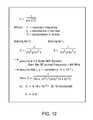
- FIG. 12is a chart illustrating calculation of frequency of resonance for the parallel tank circuit of FIG. 11 ;
- FIG. 13is a graph showing impedance versus frequency for the parallel tank bandstop circuit of FIG. 11 ;
- FIG. 14is an equation for the impedance of an inductor in parallel with a capacitor
- FIG. 15is a chart illustrating reactance equations for the inductor and the capacitor of the parallel tank circuit of FIG. 11 ;
- FIG. 16is a schematic diagram illustrating the parallel tank circuit of FIG. 11 , except in this case the inductor and the capacitor have series resistive losses;
- FIG. 17is a diagram similar to FIG. 8 , illustrating the tank circuit/bandstop filter added near a distal electrode
- FIG. 18is a schematic representation of the novel bandstop tank filter of the present invention, using switches to illustrate its function at various frequencies;
- FIG. 19is a schematic diagram similar to FIG. 18 , illustrating the low frequency model of the bandstop filter
- FIG. 20is a schematic diagram similar to FIGS. 18 and 19 , illustrating the model of the bandstop filter of the present invention at its resonant frequency;
- FIG. 21is a schematic diagram similar to FIGS. 18-20 , illustrating a model of the bandstop filter at high frequencies well above the resonant frequency;
- FIG. 22is a decision tree block diagram illustrating a process for designing the bandstop filters of the present invention.
- FIG. 23is graph of insertion loss versus frequency for bandstop filters having high Q inductors and differing quality “Q” factors;
- FIG. 24is a tracing of an exemplary patient x-ray showing an implanted pacemaker and cardioverter defibrillator and corresponding lead system;
- FIG. 25is a line drawings of an exemplary patent cardiac x-ray of a bi-ventricular lead system
- FIG. 26illustrates a bipolar cardiac pacemaker lead showing the distal TIP and the distal RING electrodes
- FIG. 27is an enlarged, fragmented schematic illustration of the area illustrated by the line 27 - 27 in FIG. 26 .
- FIG. 1illustrates of various types of active implantable medical devices 100 that are currently in use.
- FIG. 1is a wire formed diagram of a generic human body showing a number of implanted medical devices.
- 100 Ais a family of implantable hearing devices which can include the group of cochlear implants, piezoelectric sound bridge transducers and the like.
- 100 Bincludes an entire variety of neurostimulators and brain stimulators. Neurostimulators are used to stimulate the Vagus nerve, for example, to treat epilepsy, obesity and depression.
- Brain stimulatorsare similar to a pacemaker-like device and include electrodes implanted deep into the brain for sensing the onset of the seizure and also providing electrical stimulation to brain tissue to prevent the seizure from actually happening.
- 100 Cshows a cardiac pacemaker which is well-known in the art.
- 100 Dincludes the family of left ventricular assist devices (LVAD's), and artificial hearts, including the recently introduced artificial heart known as the Abiocor.
- 100 Eincludes an entire family of drug pumps which can be used for dispensing of insulin, chemotherapy drugs, pain medications and the like. Insulin pumps are evolving from passive devices to ones that have sensors and closed loop systems. That is, real time monitoring of blood sugar levels will occur. These devices tend to be more sensitive to EMI than passive pumps that have no sense circuitry or externally implanted leads.
- 100 Fincludes a variety of implantable bone growth stimulators for rapid healing of fractures.
- 100 Gincludes urinary incontinence devices.
- 100 Hincludes the family of pain relief spinal cord stimulators and anti-tremor stimulators.
- 100 Halso includes an entire family of other types of neurostimulators used to block pain.
- 100 Iincludes a family of implantable cardioverter defibrillators (ICD) devices and also includes the family of congestive heart failure devices (CHF). This is also known in the art as cardio resynchronization therapy devices, otherwise known as CRT devices.
- ICDimplantable cardioverter defibrillators
- CHFcongestive heart failure devices
- the AIMD 100could, for example, be a cardiac pacemaker 100 C which is enclosed by a titanium housing 102 as indicated.
- the titanium housingis hermetically sealed, however there is a point where leads 104 must ingress and egress the hermetic seal.
- Hermetic terminal assembliesare well known and generally consist of a ferrule 108 which is laser welded to the titanium housing 102 of the AIMD 100 .
- the hermetic terminal assembly 106 with its associated EMI filteris better shown in FIG. 3 .
- four leadsare shown consisting of lead pair 104 a and 104 b and lead pair 104 c and 104 d . This is typical of what's known as a dual chamber bipolar cardiac pacemaker.
- the ISI connectors 110 that are designed to plug into the header block 112are low voltage (pacemaker) connectors covered by an ANSI/AAMI standard IS-1. Higher voltage devices, such as implantable cardioverter defibrillators, are covered by a standard known as the ANSI/AAMI DF-1. There is a new standard under development which will integrate both high voltage and low voltage connectors into a new miniature connector series known as the IS-4 series. These connectors are typically routed in a pacemaker application down into the right ventricle and right atrium of the heart 114 . There are also new generation devices that have been introduced to the market that couple leads to the outside of the left ventricle. These are known as biventricular devices and are very effective in cardiac resynchronization therapy (CRT) and treating congestive heart failure (CHF).
- CTRcardiac resynchronization therapy
- CHFcongestive heart failure
- the bipolar leads 104 a and 104 bthat could be routed, for example, to the distal TIP and RING into the right ventricle.
- the bipolar leads 104 c and 104 dcould be routed to a distal TIP and RING in the right atrium.
- AIMDsimplantable cardioverter defibrillators
- neurostimulatorsincluding deep brain stimulators, spinal cord stimulators, cochlear implants, incontinence stimulators and the like, and drug pumps.
- ICDsimplantable cardioverter defibrillators
- neurostimulatorsincluding deep brain stimulators, spinal cord stimulators, cochlear implants, incontinence stimulators and the like, and drug pumps.
- the present inventionis also applicable to a wide variety of minimally invasive AIMDs. For example, in certain hospital cath lab procedures, one can insert an AIMD for temporary use such as an ICD. Ventricular assist devices also can fall into this type of category. This list is not meant to be limiting, but is only example of the applications of the novel technology currently described herein.
- FIG. 3is an enlarged, fragmented cross-sectional view taken generally along line 3 - 3 of FIG. 2 .
- the RF telemetry pin 116 and the bipolar leads 104 a and 104 cwhich would be routed to the cardiac chambers by connecting these leads to the internal connectors 118 of the IS-1 header block 112 ( FIG. 2 ).
- These connectorsare designed to receive the plug 110 which allows the physicians to thread leads through the venous system down into the appropriate chambers of the heart 114 . It will be obvious to those skilled in the art that tunneling of deep brain electrodes or neurostimulators are equivalent.
- feedthrough capacitor 120which has been bonded to the hermetic terminal assembly 106 .
- feedthrough capacitorsare well known in the art and are described and illustrated in U.S. Pat. Nos. 5,333,095, 5,751,539, 5,978,204, 5,905,627, 5,959,829, 5,973,906, 5,978,204, 6,008,980, 6,159,560, 6,275,369, 6,424,234, 6,456,481, 6,473,291, 6,529,103, 6,566,978, 6,567,259, 6,643,903, 6,675,779, 6,765,780 and 6,882,248.
- a rectangular quadpolar feedthrough capacitor 120which has an external metalized termination surface 122 . It includes embedded electrode plate sets 124 and 126 . Electrode plate set 124 is known as the ground electrode plate set and is terminated at the outside of the capacitor 120 at the termination surface 122 . These ground electrode plates 124 are electrically and mechanically connected to the ferrule 108 of the hermetic terminal assembly 106 using a thermosetting conductive polyimide or equivalent material 128 (equivalent materials will include solders, brazes, conductive epoxies and the like). In turn, the hermetic seal terminal assembly 106 is designed to have its titanium ferrule 108 laser welded 130 to the overall housing 102 of the AIMD 100 . This forms a continuous hermetic seal thereby preventing body fluids from penetrating into and causing damage to the electronics of the AIMD.
- the leads 104 and insulator 136be hermetically sealed, such as by the gold brazes or glass seals 132 and 134 .
- the gold braze 132wets from the titanium ferrule 108 to the alumina ceramic insulator 136 .
- the ceramic alumina insulator 136is also gold brazed at 134 to each of the leads 104 .
- the RF telemetry pin 116is also gold brazed at 138 to the alumina ceramic insulator 136 . It will be obvious to those skilled in the art that there are a variety of other ways of making such a hermetic terminal. This would include glass sealing the leads into the ferrule directly without the need for the gold brazes.
- the RF telemetry pin 116has not been included in the area of the feedthrough capacitor 120 .
- the reason for thisis the feedthrough capacitor 120 is a very broadband single element EMI filter which would eliminate the desirable telemetry frequency.
- FIG. 4is a bottom view taken generally along line 4 - 4 in FIG. 3 .
- FIG. 5is an isometric view of the feedthrough capacitor 120 .
- the termination surface 122connects to the capacitor's internal ground plate set 124 .
- ground plate set 124which is typically silk-screened onto ceramic layers, is brought out and exposed to the termination surface 122 .
- the capacitor's four (quad polar) active electrode plate sets 126are illustrated in FIG. 7 .
- the leads 104are in non-electrical communication with the ground electrode plate set 124 .
- each one of the leads 104is in electrical contact with its corresponding active electrode plate set 126 .
- the amount of capacitanceis determined by the overlap of the active electrode plate area 126 over the ground electrode plate area.
- the capacitance valueis also related to the dielectric thickness or spacing between the ground electrode set 124 and the active electrode set 126 . Reducing the dielectric thickness increases the capacitance significantly while at the same time reducing its voltage rating. This gives the designer many degrees of freedom in selecting the capacitance value.
- FIG. 8is a general diagram of a unipolar active implantable medical device system 100 .
- the housing 102 of the active implantable medical device 100is typically titanium, ceramic, stainless steel or the like. Inside of the device housing are the AIMD electronic circuits.
- AIMDsinclude a battery, but that is not always the case. For example, for a Bion, it can receive its energy from an external pulsing magnetic field.
- a lead 104is routed from the AIMD 100 to a point 140 where it is embedded in or affixed to body tissue.
- the distal TIP 140could be in the spinal cord.
- the distal electrode 140would be placed deep into the brain, etc.
- the distal electrode 140would typically be placed in the cardiac right ventricle.
- FIG. 9is very similar to FIG. 8 except that it is a bipolar system.
- the electric circuit return pathis between the two distal electrodes 140 and 140 ′.
- thiswould be known as a bipolar lead system with one of the electrodes known as the distal TIP 142 and the other electrode which would float in the blood pool known as the RING 144 (see FIG. 10 ).
- the electrical return path in FIG. 8is between the distal electrode 140 through body tissue to the conductive housing 102 of the implantable medical device 100 .
- FIG. 10illustrates a bipolar lead system with a distal TIP 142 and RING 144 typically as used in a cardiac pacemaker 100 C.
- the patientcould be exposed to the fields of an MRI scanner or other powerful emitter used during a medical diagnostic procedure.
- Currents that are directly induced in the lead system 104can cause heating by I 2 R losses in the lead system or by heating caused by current flowing in body tissue. If these currents become excessive, the associated heating can cause damage or even destructive ablation to body tissue.
- the distal TIP 142is designed to be implanted into or affixed to the actual myocardial tissue of the heart.
- the RING 144is designed to float in the blood pool. Because the blood is flowing and is thermally conductive, the RING 144 structure is substantially cooled. In theory, however, if the lead curves, the RING 144 could also touch and become encapsulated by body tissue.
- the distal TIP 142is always thermally insulated by surrounding body tissue and can readily heat up due to the RF pulse currents of an MRI field.
- FIG. 11is a schematic diagram showing a parallel combination of an inductor L and a capacitor C to be placed in the implantable lead systems 104 previously described. This combination forms a parallel tank circuit or bandstop filter 146 which will resonate at a particular frequency (f r ).
- FIG. 12gives the frequency of resonance equation f r for the parallel tank circuit 146 of FIG. 11 : where f r is the frequency of resonance in hertz, L is the inductance in henries and C is the capacitance in farads.
- MRI systemsvary in static field strength from 0.5 Tesla all the way up to 3 Tesla with newer research machines going much higher. This is the force of the main static magnetic field.
- the frequency of the pulsed RF field associated with MRIis found by multiplying the static field in Teslas times 42.45. Accordingly, a 3 Tesla MRI system has a pulsed RF field of approximately 128 MHz.
- the inductor value Lis equal to one nanohenry. The one nanohenry comes from the fact that given the small geometries involved inside of the human body, a very large inductor will not be possible.
- the relationship between the parallel inductor L and capacitor Cis also very important. It has been discovered that maximizing the inductance for the space available will change the L-C ratios and lead to a higher impedance at resonance. Accordingly, it is preferred to include as much reasonable inductance as is possible into a small space and then solve for the capacitance values. For example, a typical bandstop filter might utilize inductance of 440 nanohenries in parallel with capacitance of 15.9 picofarads. In another embodiment, where space is limited, the maximum inductance achievable is 180 nanohenries in a device designed to meet a 5-amp AED pulse rating.
- the values of capacitance and inductancebe selected within the range of 0.1-20,000 picofarads and 1-4000 nanohenries, respectively, such that the bandstop filter is resonant at the selected frequency.
- the capacitancewould be in the range from 1-100 picofarads and the inductance would be in the range from 100-1000 nanohenries.
- an air wound inductoris the ideal choice because it is not affected by MRI signals or fields. Because of the space limitations, however, the inductor will not be very volumetrically efficient. For this reason, it is preferable to keep the inductance value relatively low (in the order of 1 to 100 nanohenries).
- FIG. 13is a graph showing impedance versus frequency for the parallel tank, bandstop filter circuit 146 of FIG. 11 .
- the impedance measured between points A and B for the parallel tank circuit 146 shown in FIG. 11is very low (zero) until one approaches the resonant frequency f r .
- these ideal componentscombine together to look like a very high or, ideally, an infinite impedance. The reason for this comes from the denominator of the equation Z ab for the impedance for the inductor in parallel with the capacitor shown as FIG. 14 .
- the inductive reactanceis equal to the capacitive reactance, the two imaginary vectors cancel each other and go to zero. Referring to the equations in FIGS.
- a cardiac pacemakerit would be possible, for example, in the case of a cardiac pacemaker, to design the cardiac pacemaker for compatibility with one single popular MRI system.
- the pacemaker lead systemhas been designed to be compatible with 3 Tesla MRI systems.
- a distal TIP bandstop filter 146would be incorporated where the L and the C values have been carefully selected to be resonant at 128 MHz, presenting a high or almost infinite impedance at the MRI pulse frequency.
- FIG. 16is a schematic drawing of the parallel tank circuit 146 of FIG. 11 , except in this case the inductor L and the capacitor C are not ideal. That is, the capacitor C has its own internal resistance R C , which is otherwise known in the industry as dissipation factor or equivalent series resistance (ESR).
- the inductor Lalso has a resistance R L . For those that are experienced in passive components, one would realize that the inductor L would also have some parallel capacitance. This parasitic capacitance comes from the capacitance associated with adjacent turns. However, the inductance value contemplated is so low that one can assume that at MRI pulse frequencies, the inductor's parallel capacitance is negligible.
- the capacitor Calso has some internal inductance which would appear in series.
- the novel capacitors described beloware very small or coaxial and have negligible series inductance. Accordingly, the circuit shown in FIG. 16 is a very good approximation model for the novel parallel tank circuits 146 as described herein.
- the frequency fis close to zero (DC)
- biologic signalsare low frequency, typically between 10 Hz and 1000 Hz.
- the inductive reactance X Lwill be very close to zero ohms.
- the impedance between points A and B in FIG. 16will equal to R L .
- the resistance of the inductor (R L )should be kept as small as possible to minimize attenuation of biologic signals or attenuation of stimulation pulses to body tissues. This will allow biologic signals to pass through the bandstop filter 146 freely. It also indicates that the amount of capacitive loss R C is not particularly important.
- FIG. 17is a drawing of the unipolar AIMD lead system, previously shown in FIG. 8 , with the bandstop filter 146 of the present invention added near the distal electrode 140 .
- the presence of the tank circuit 146will present a very high impedance at one or more specific MRI RF pulse frequencies. This will prevent currents from circulating through the distal electrode 140 into body tissue at this selected frequency(s). This will provide a very high degree of important protection to the patient so that overheating does not cause tissue damage.
- FIG. 18is a representation of the novel bandstop filter 146 using switches that open and close at various frequencies to illustrate its function.
- Inductor Lhas been replaced with a switch S L .
- the switch S LWhen the impedance of the inductor is quite low, the switch S L will be closed.
- the impedance or inductive reactance of the inductorWhen the impedance or inductive reactance of the inductor is high, the switch S L will be shown open.
- the capacitor element CWhen the capacitive reactance looks like a very low impedance, the capacitor switch S C will be shown closed. When the capacitive reactance is shown as a very high impedance, the switch S C will be shown open. This analogy is best understood by referring to FIGS. 19 , 20 and 21 .
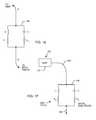
- FIG. 19is the low frequency model of the bandstop filter 146 .
- capacitorstend to look like open circuits and inductors tend to look like short circuits. Accordingly, switch S L is closed and switch S C is open. This is an indication that at frequencies below the resonant frequency of the bandstop filter 146 that currents will flow only through the inductor element and its corresponding resistance R L .
- the implantable medical deviceis also sensing biological frequencies in the same frequency range.
- FIG. 20is a model of the novel bandstop filter 146 at its resonant frequency.
- a parallel tank circuitis at resonance, it presents a very high impedance to the overall circuit. Accordingly, both switches S L and S C are shown open. For example, this is how the bandstop filter 146 prevents the flow of MRI currents through pacemaker leads and/or into body tissue at a selected MRI RF pulsed frequency.
- FIG. 21is a model of the bandstop filter 146 at high frequency.
- inductorstend to look like open circuits. Accordingly, switch S L is shown open.
- switch S Cis closed. It should be noted that real capacitors are not ideal and tend to degrade in performance at high frequency. This is due to the capacitor's equivalent series inductance and equivalent series resistance. Fortunately, for the present invention, it is not important how lossy (resistive) the capacitor element C gets at high frequency. This will only serve to attenuate unwanted electromagnetic interference from flowing in the lead system.
- the equivalent series resistance R C and resulting quality factor of the capacitor element Cis not nearly as important as the quality factor of the inductor element L.
- the equation for inductive reactance (X L )is given in FIG. 15 .
- the capacitor reactance equation (X C )is also given in FIG. 15 .
- FIG. 22is a decision tree block diagram that better illustrates the design process herein.
- Block 148is an initial decision step the designer must make.
- This value of inductanceis generally going to relate to the amount of space available in the AIMD lead system and other factors. These values for practical purposes generally range in inductance value from one nanohenry up to about 4000 nanohenries. This puts practical boundaries on the amount of inductance that can be effectively packaged within the scope of the present invention.
- onewill typically select an inductance value generally ranging from 100-1000 nanohenries, and then solve for a corresponding capacitance value required to be self-resonant at the selected MRI Lamour frequency.
- block 150one does an assessment of the overall packaging requirements of a distal TIP 142 bandstop filter 146 and then assumes a realizable capacitance value. So, in decision block 150 , we assume a capacitor value.
- f rthe required value of inductance (L).
- inductance valueis realizable, then we go on to block 154 and finalize the design. If the inductance value is not realizable within the physical and practical constraints, then we need to go back to block 150 and assume a new value of capacitance. One may go around this loop a number of times until one finally comes up with a compatible capacitor and an inductor design. In some cases, one will not be able to achieve a final design using this alone. In other words, one may have to use a custom capacitor value or design in order to achieve a result that meets all of the design criteria.
- step 160After one finds the desired amount of capacitance C, one then determines whether that custom value of capacitance will fit into the design parameters. If the capacitance value that is determined in step 160 is realizable, then one goes on and finalizes the design. However, if it is not realizable, then one can go back up to step 156 , assume a different value of L and go through the decision tree again. This is done over and over until one finds combinations of L and C that are practical for the overall design.
- the predetermined frequencywould be the MRI pulsed frequency.
- Efficiency of the overall tank circuit 146is also measured in terms of a quality factor, Q, although this factor is defined differently than the one previously mentioned for discrete capacitors and inductors.
- Qquality factor
- the “Q” or quality factor of the tank circuitis very important. As mentioned, it is desirable to have a very low loss circuit at low frequencies such that the biological signals not be undesirably attenuated.
- the quality factornot only determines the loss of the filter, but also affects its 3 dB bandwidth. If one does a plot of the filter response curve (Bode plot), the 3 dB bandwidth determines how sharply the filter will rise and fall. With reference to curve 166 of FIG. 23 , for a tank that is resonant at 128 MHz, an ideal response would be one that had infinite attenuation at 128 MHz, but had zero attenuation at low frequencies below 1 KHz.
- the performance of the circuitis directly related to the efficiency of both the inductor and the capacitor; the less efficient each component is, the more heat loss that results, and this can be expressed by the addition of resistor elements to the ideal circuit diagram.
- the effect of lower Q in the tank circuitis to broaden the resonance peak about the resonance frequency. By deliberately using a low Q capacitor, one can broaden the resonance such that a high impedance (high attenuation) is presented at multiple MRI RF frequencies, for example 64 MHz and 128 MHz.
- curve 164wherein a low resistive loss high Q inductor has been used in combination with a relatively high ESR low Q capacitor. This has a very desirable effect in that at very low frequencies, the impedance of the tank circuit 146 is essentially zero ohms (or zero dB loss). This means that biologic frequencies are not undesirably attenuated. However, one can see that the 3 db bandwidth is much larger. This is desirable as it will block multiple RF frequencies. As one goes even higher in frequency, curve 164 will desirably attenuate other high frequency EMI signals, such as those from cellular telephones, microwave ovens and the like.
- R CBy adding a separate discrete component in series with the capacitor element. For example, one could install a small capacitor chip that had a very low equivalent series resistance and place it in series with a resistor chip. This would be done to deliberately raise the value of R C in the circuit as shown in FIG. 17 . By carefully adjusting this value of R C , one could then achieve the ideal curve 164 as shown in FIG. 23 .
- FIG. 24is a tracing of an actual patient X-ray. This particular patient required both a cardiac pacemaker 100 C and an implantable cardioverter defibrillator 1001 .
- the corresponding implantable lead system 104makes for a very complicated antenna and loop coupling situation. The reader is referred to the article entitled, “Estimation of Effective Lead Loop Area for Implantable Pulse Generator and Implantable Cardioverter Defibrillators” provided by the AAMI Pacemaker EMC Task Force.
- the bandstop filters 146 of the present inventionwould need to be placed at least in the distal TIP in the right atrium and the distal TIP in the right ventricle from the cardiac pacemaker.
- ICDimplantable cardioverter defibrillator
- ICDsimplantable cardioverter defibrillators
- FIG. 25is a line drawing of an actual patient cardiac X-ray of one of the newer bi-ventricular lead systems with various types of electrode TIPS shown.
- the new bi-ventricular systemsare being used to treat congestive heart failure, and make it possible to implant leads outside of the left ventricle. This makes for a very efficient pacing system; however, the implantable lead system 104 is quite complex.
- a lead system 104such as those described in FIGS. 8 , 9 , 10 and 11 , are exposed to a time varying electromagnetic field, electric currents can be induced into such lead systems.
- bandstop filters 146would be required at each of the three distal TIPs and optionally at RING and SVC locations.
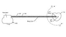
- FIG. 26illustrates a single chamber bipolar cardiac pacemaker lead showing the distal TIP 142 and the distal RING 144 electrodes. This is a spiral wound system where the RING coil 104 is wrapped around the TIP coil 104 ′. There are other types of pacemaker lead systems in which these two leads lay parallel to one another (known as a bifilar lead system).
- FIG. 27is a schematic illustration of the area 27 - 27 in FIG. 26 .
- bandstop filters 146 and 146 ′have been placed in series with each of the respective TIP and RING circuits. Accordingly, at MRI pulsed frequencies, an open circuit will be presented thereby stopping the flow of undesirable RF current.
Landscapes
- Health & Medical Sciences (AREA)
- General Health & Medical Sciences (AREA)
- Physics & Mathematics (AREA)
- Radiology & Medical Imaging (AREA)
- Biomedical Technology (AREA)
- Veterinary Medicine (AREA)
- Public Health (AREA)
- Cardiology (AREA)
- Heart & Thoracic Surgery (AREA)
- Engineering & Computer Science (AREA)
- Animal Behavior & Ethology (AREA)
- Nuclear Medicine, Radiotherapy & Molecular Imaging (AREA)
- Life Sciences & Earth Sciences (AREA)
- Pathology (AREA)
- Condensed Matter Physics & Semiconductors (AREA)
- Electromagnetism (AREA)
- General Physics & Mathematics (AREA)
- Electrotherapy Devices (AREA)
Abstract
Description
- (a) RF field coupling to the lead can occur which induces significant local heating; and
- (b) currents induced between the distal TIP and tissue during MRI RF pulse transmission sequences can cause local Ohms Law heating in tissue next to the distal TIP electrode of the implanted lead. The RF field of an MRI scanner can produce enough energy to induce lead currents sufficient to destroy some of the adjacent myocardial tissue. Tissue ablation has also been observed. The effects of this heating are not readily detectable by monitoring during the MRI. Indications that heating has occurred would include an increase in pacing threshold, venous ablation, Larynx or e ablation, myocardial perforation and lead penetration, or even arrhythmias caused by scar tissue. Such long term heating effects of MRI have not been well studied yet for all types of AIMD lead geometries. There can also be localized heating problems associated with various types of electrodes in addition to TIP electrodes. This includes RING electrodes or PAD electrodes. RING electrodes are commonly used with a wide variety of implanted devices including cardiac pacemakers, and neurostimulators, and the like. PAD electrodes are very common in neurostimulator applications. For example, spinal cord stimulators or deep brain stimulators can include a plurality of PAD electrodes to make contact with nerve tissue. A good example of this also occurs in a cochlear implant. In a typical cochlear implant there would be sixteen RING electrodes that the physician places by pushing the electrode up into the cochlea. Several of these RING electrodes make contact with auditory nerves.
- (5) Alterations of pacing rate due to the applied radio frequency field. It has been observed that the RF field may induce undesirable fast pacing (QRS complex) rates. There are various mechanisms which have been proposed to explain rapid pacing: direct tissue stimulation, interference with pacemaker electronics or pacemaker reprogramming (or reset). In all of these cases, it is very desirable to raise the lead system impedance (at the MRI RF pulsed frequency) to make an EMI filter feedthrough capacitor more effective and thereby provide a higher degree of protection to AIMD electronics. This will make alterations in pacemaker pacing rate and/or pacemaker reprogramming much more unlikely.
- (6) Time-varying magnetic gradient fields. The contribution of the time-varying gradient to the total strength of the MRI magnetic field is negligible, however, pacemaker systems could be affected because these fields are rapidly applied and removed. The time rate of change of the magnetic field is directly related to how much electromagnetic force and hence current can be induced into a lead system. Luchinger reports that even using today's gradient systems with a time-varying field up to 50 Tesla per second, the induced currents are likely to stay below the biological thresholds for cardiac fibrillation. A theoretical upper limit for the induced voltage by the time-varying magnetic gradient field is 20 volts. Such a voltage during more than 0.1 milliseconds could be enough energy to directly pace the heart.
- (7) Heating. Currents induced by time-varying magnetic gradient fields may lead to local heating. Researchers feel that the calculated heating effect of the gradient field is much less as compared to that caused by the RF field and therefore for the purposes herein may be neglected.
Where fris the resonance frequency, and Δf3dBshown as points a and b in
Claims (11)
Priority Applications (7)
| Application Number | Priority Date | Filing Date | Title |
|---|---|---|---|
| US12/707,084US8977355B2 (en) | 2001-04-13 | 2010-02-17 | EMI filter employing a capacitor and an inductor tank circuit having optimum component values |
| EP10172547AEP2357017A1 (en) | 2010-02-17 | 2010-08-11 | Emi filter employing a capacitor and an inductor tank circuit having optimum component values |
| US12/891,292US8437865B2 (en) | 2001-04-13 | 2010-09-27 | Shielded network for an active medical device implantable lead |
| US13/860,191US8670841B2 (en) | 2001-04-13 | 2013-04-10 | Implantable lead having a shielded bandstop filter comprising a self-resonant inductor for an active medical device |
| US13/860,888US8712544B2 (en) | 2001-04-13 | 2013-04-11 | Electromagnetic shield for a passive electronic component in an active medical device implantable lead |
| US14/185,085US8918189B2 (en) | 2001-04-13 | 2014-02-20 | Implantable lead having a shielded bandstop filter comprising a self-resonant inductor for an active medical device |
| US14/247,277US9008799B2 (en) | 2006-06-08 | 2014-04-08 | EMI filter employing a self-resonant inductor bandstop filter having optimum inductance and capacitance values |
Applications Claiming Priority (4)
| Application Number | Priority Date | Filing Date | Title |
|---|---|---|---|
| US28372501P | 2001-04-13 | 2001-04-13 | |
| US10/123,534US7844319B2 (en) | 1998-11-04 | 2002-04-15 | Systems and methods for magnetic-resonance-guided interventional procedures |
| US11/423,073US8244370B2 (en) | 2001-04-13 | 2006-06-08 | Band stop filter employing a capacitor and an inductor tank circuit to enhance MRI compatibility of active medical devices |
| US12/707,084US8977355B2 (en) | 2001-04-13 | 2010-02-17 | EMI filter employing a capacitor and an inductor tank circuit having optimum component values |
Related Parent Applications (4)
| Application Number | Title | Priority Date | Filing Date |
|---|---|---|---|
| US10/123,534Continuation-In-PartUS7844319B2 (en) | 1998-11-04 | 2002-04-15 | Systems and methods for magnetic-resonance-guided interventional procedures |
| US11/423,073Continuation-In-PartUS8244370B2 (en) | 1998-11-04 | 2006-06-08 | Band stop filter employing a capacitor and an inductor tank circuit to enhance MRI compatibility of active medical devices |
| US12/607,234Continuation-In-PartUS8175700B2 (en) | 2001-04-13 | 2009-10-28 | Capacitor and inductor elements physically disposed in series whose lumped parameters are electrically connected in parallel to form a bandstop filter |
| US12/891,292Continuation-In-PartUS8437865B2 (en) | 2001-04-13 | 2010-09-27 | Shielded network for an active medical device implantable lead |
Related Child Applications (4)
| Application Number | Title | Priority Date | Filing Date |
|---|---|---|---|
| US11/558,349Continuation-In-PartUS7945322B2 (en) | 1998-11-04 | 2006-11-09 | Tank filters placed in series with the lead wires or circuits of active medical devices to enhance MRI compatibility |
| US12/873,862Continuation-In-PartUS8224440B2 (en) | 2001-04-13 | 2010-09-01 | Electrically isolating electrical components in a medical electrical lead with an active fixation electrode |
| US12/891,292Continuation-In-PartUS8437865B2 (en) | 2001-04-13 | 2010-09-27 | Shielded network for an active medical device implantable lead |
| US14/247,277ContinuationUS9008799B2 (en) | 2006-06-08 | 2014-04-08 | EMI filter employing a self-resonant inductor bandstop filter having optimum inductance and capacitance values |
Publications (2)
| Publication Number | Publication Date |
|---|---|
| US20100198312A1 US20100198312A1 (en) | 2010-08-05 |
| US8977355B2true US8977355B2 (en) | 2015-03-10 |
Family
ID=44123397
Family Applications (2)
| Application Number | Title | Priority Date | Filing Date |
|---|---|---|---|
| US12/707,084Active2027-10-11US8977355B2 (en) | 2001-04-13 | 2010-02-17 | EMI filter employing a capacitor and an inductor tank circuit having optimum component values |
| US14/247,277ActiveUS9008799B2 (en) | 2006-06-08 | 2014-04-08 | EMI filter employing a self-resonant inductor bandstop filter having optimum inductance and capacitance values |
Family Applications After (1)
| Application Number | Title | Priority Date | Filing Date |
|---|---|---|---|
| US14/247,277ActiveUS9008799B2 (en) | 2006-06-08 | 2014-04-08 | EMI filter employing a self-resonant inductor bandstop filter having optimum inductance and capacitance values |
Country Status (2)
| Country | Link |
|---|---|
| US (2) | US8977355B2 (en) |
| EP (1) | EP2357017A1 (en) |
Cited By (5)
| Publication number | Priority date | Publication date | Assignee | Title |
|---|---|---|---|---|
| US10154616B2 (en) | 2012-09-05 | 2018-12-11 | Avx Corporation | Electromagnetic interference filter for implanted electronics |
| US10363425B2 (en) | 2015-06-01 | 2019-07-30 | Avx Corporation | Discrete cofired feedthrough filter for medical implanted devices |
| WO2020068859A1 (en)* | 2018-09-24 | 2020-04-02 | The Curators Of The University Of Missouri | Model-based sensor technology for detection of cardiovascular status |
| WO2020150241A1 (en)* | 2019-01-16 | 2020-07-23 | Rhythmlink International, Llc | Neurological monitoring cable for magnetic resonance environments |
| US10874865B2 (en) | 2017-11-06 | 2020-12-29 | Avx Corporation | EMI feedthrough filter terminal assembly containing a resin coating over a hermetically sealing material |
Families Citing this family (40)
| Publication number | Priority date | Publication date | Assignee | Title |
|---|---|---|---|---|
| US8244370B2 (en) | 2001-04-13 | 2012-08-14 | Greatbatch Ltd. | Band stop filter employing a capacitor and an inductor tank circuit to enhance MRI compatibility of active medical devices |
| WO2002040088A2 (en)* | 2000-11-20 | 2002-05-23 | Surgi-Vision, Inc. | Connector and guidewire connectable thereto |
| US20070088416A1 (en)* | 2001-04-13 | 2007-04-19 | Surgi-Vision, Inc. | Mri compatible medical leads |
| US8219208B2 (en) | 2001-04-13 | 2012-07-10 | Greatbatch Ltd. | Frequency selective passive component networks for active implantable medical devices utilizing an energy dissipating surface |
| US8155760B2 (en)* | 2001-04-13 | 2012-04-10 | Greatbatch Ltd. | Medical lead system utilizing electromagnetic bandstop filters |
| CA2575313C (en)* | 2004-07-27 | 2013-07-23 | Surgivision, Inc. | Mri systems having mri compatible universal delivery cannulas with cooperating mri antenna probes and related systems and methods |
| EP1776040A4 (en)* | 2004-08-09 | 2012-02-15 | Univ Johns Hopkins | IMPLANTABLE MRI-COMPATIBLE PACING AND ANTENNAS AND ASSOCIATED SYSTEMS AND METHODS |
| CA2606824C (en)* | 2005-05-04 | 2015-11-24 | Surgi-Vision, Inc. | Improved electrical lead for an electronic device such as an implantable device |
| CA2623453C (en) | 2005-10-21 | 2016-02-09 | Surgi-Vision, Inc. | Mri-safe high impedance lead systems and related methods |
| US8224462B2 (en) | 2005-11-11 | 2012-07-17 | Greatbatch Ltd. | Medical lead system utilizing electromagnetic bandstop filters |
| WO2008115426A1 (en)* | 2007-03-19 | 2008-09-25 | Boston Scientific Neuromodulation Corporation | Mri and rf compatible leads and related methods of operating and fabricating leads |
| ES2605170T3 (en) | 2007-03-19 | 2017-03-13 | Boston Scientific Neuromodulation Corporation | Cable manufacturing procedures and apparatus with conductors and related flexible cable configurations |
| CA2715015A1 (en)* | 2008-03-17 | 2009-09-24 | Surgivision, Inc. | Low profile medical devices with internal drive shafts that cooperate with releasably engageable drive tools and related methods |
| US10080889B2 (en) | 2009-03-19 | 2018-09-25 | Greatbatch Ltd. | Low inductance and low resistance hermetically sealed filtered feedthrough for an AIMD |
| US8996126B2 (en) | 2009-02-04 | 2015-03-31 | Greatbatch Ltd. | Composite RF current attenuator for a medical lead |
| US20120256704A1 (en)* | 2011-03-01 | 2012-10-11 | Greatbatch Ltd. | Rf filter for an active medical device (amd) for handling high rf power induced in an associated implanted lead from an external rf field |
| JP2012049434A (en)* | 2010-08-30 | 2012-03-08 | Sony Corp | Electronic component, feeder device, power receiver, and wireless feeder system |
| EP2486952A1 (en) | 2011-02-14 | 2012-08-15 | Greatbatch Ltd. | Medical lead system utilizing electromagnetic bandstop filters |
| US10350421B2 (en) | 2013-06-30 | 2019-07-16 | Greatbatch Ltd. | Metallurgically bonded gold pocket pad for grounding an EMI filter to a hermetic terminal for an active implantable medical device |
| US9931514B2 (en) | 2013-06-30 | 2018-04-03 | Greatbatch Ltd. | Low impedance oxide resistant grounded capacitor for an AIMD |
| US9757558B2 (en) | 2011-03-01 | 2017-09-12 | Greatbatch Ltd. | RF filter for an active medical device (AMD) for handling high RF power induced in an associated implanted lead from an external RF field |
| US11198014B2 (en) | 2011-03-01 | 2021-12-14 | Greatbatch Ltd. | Hermetically sealed filtered feedthrough assembly having a capacitor with an oxide resistant electrical connection to an active implantable medical device housing |
| US10272252B2 (en) | 2016-11-08 | 2019-04-30 | Greatbatch Ltd. | Hermetic terminal for an AIMD having a composite brazed conductive lead |
| US9427596B2 (en) | 2013-01-16 | 2016-08-30 | Greatbatch Ltd. | Low impedance oxide resistant grounded capacitor for an AIMD |
| US10596369B2 (en) | 2011-03-01 | 2020-03-24 | Greatbatch Ltd. | Low equivalent series resistance RF filter for an active implantable medical device |
| USD736383S1 (en) | 2012-11-05 | 2015-08-11 | Nevro Corporation | Implantable signal generator |
| EP2773423B1 (en) | 2011-11-04 | 2024-01-10 | Nevro Corporation | Medical device communication and charding assemblies for use with implantable signal generators |
| USRE46699E1 (en) | 2013-01-16 | 2018-02-06 | Greatbatch Ltd. | Low impedance oxide resistant grounded capacitor for an AIMD |
| WO2016081611A1 (en) | 2014-11-19 | 2016-05-26 | Advanced Cardiac Therapeutics, Inc. | High-resolution mapping of tissue with pacing |
| JP6725178B2 (en) | 2014-11-19 | 2020-07-15 | エピックス セラピューティクス,インコーポレイテッド | Ablation apparatus, systems and methods using high resolution electrode assemblies |
| JP6825789B2 (en) | 2014-11-19 | 2021-02-03 | エピックス セラピューティクス,インコーポレイテッド | Systems and methods for high resolution mapping of tissues |
| US9636511B2 (en)* | 2015-01-23 | 2017-05-02 | Medtronic, Inc. | Tissue conduction communication (TCC) transmission |
| US9636164B2 (en) | 2015-03-25 | 2017-05-02 | Advanced Cardiac Therapeutics, Inc. | Contact sensing systems and methods |
| WO2017160808A1 (en) | 2016-03-15 | 2017-09-21 | Advanced Cardiac Therapeutics, Inc. | Improved devices, systems and methods for irrigated ablation |
| US10249415B2 (en) | 2017-01-06 | 2019-04-02 | Greatbatch Ltd. | Process for manufacturing a leadless feedthrough for an active implantable medical device |
| CN110809448B (en) | 2017-04-27 | 2022-11-25 | Epix疗法公司 | Determining properties of contact between catheter tip and tissue |
| US10912945B2 (en) | 2018-03-22 | 2021-02-09 | Greatbatch Ltd. | Hermetic terminal for an active implantable medical device having a feedthrough capacitor partially overhanging a ferrule for high effective capacitance area |
| US10905888B2 (en) | 2018-03-22 | 2021-02-02 | Greatbatch Ltd. | Electrical connection for an AIMD EMI filter utilizing an anisotropic conductive layer |
| WO2020174330A1 (en)* | 2019-02-26 | 2020-09-03 | Cochlear Limited | Prosthesis operation in the face of magnetic fields |
| US12344566B2 (en) | 2021-09-10 | 2025-07-01 | Greatbatch Ltd. | Methods for making a ceramic reinforced metal composite for hermetic bodies for implantable devices |
Citations (189)
| Publication number | Priority date | Publication date | Assignee | Title |
|---|---|---|---|---|
| US3871382A (en) | 1973-02-15 | 1975-03-18 | Pacesetter Syst | Heart stimulator system for rapid implantation and removal with improved integrity |
| US3968802A (en) | 1975-01-24 | 1976-07-13 | Medtronic, Inc. | Cautery protection circuit for a heart pacemaker |
| US4295467A (en) | 1979-05-24 | 1981-10-20 | Inverness International Corp. | Electrolysis apparatus with retractable probe |
| US4431005A (en) | 1981-05-07 | 1984-02-14 | Mccormick Laboratories, Inc. | Method of and apparatus for determining very accurately the position of a device inside biological tissue |
| US4445501A (en) | 1981-05-07 | 1984-05-01 | Mccormick Laboratories, Inc. | Circuits for determining very accurately the position of a device inside biological tissue |
| JPS60141034A (en) | 1983-12-09 | 1985-07-26 | コックリアー コーポレーション | Signal transmitter |
| US4572198A (en) | 1984-06-18 | 1986-02-25 | Varian Associates, Inc. | Catheter for use with NMR imaging systems |
| JPS61181925A (en) | 1985-02-06 | 1986-08-14 | Toyo Commun Equip Co Ltd | Temperature sensor |
| US4633181A (en) | 1983-08-11 | 1986-12-30 | Regents Of The University Of Calif. | Apparatus and method for increasing the sensitivity of a nuclear magnetic resonance probe |
| US4643186A (en) | 1985-10-30 | 1987-02-17 | Rca Corporation | Percutaneous transluminal microwave catheter angioplasty |
| US4654880A (en) | 1983-12-09 | 1987-03-31 | Minnesota Mining And Manufacturing Company | Signal transmission system |
| US4672972A (en) | 1984-08-13 | 1987-06-16 | Berke Howard R | Solid state NMR probe |
| WO1987004080A2 (en) | 1986-01-13 | 1987-07-16 | Donald Bernard Longmore | Surgical catheters |
| US4689621A (en) | 1986-03-31 | 1987-08-25 | The United States Of America As Represented By The Administrator Of The National Aeronautics And Space Administration | Temperature responsive transmitter |
| US4754752A (en) | 1986-07-28 | 1988-07-05 | Robert Ginsburg | Vascular catheter |
| US4757820A (en) | 1985-03-15 | 1988-07-19 | Kabushiki Kaisha Toshiba | Ultrasound therapy system |
| US4766381A (en) | 1987-08-12 | 1988-08-23 | Vanderbilt University | Driven inversion spin echo magnetic resonance imaging |
| US4799499A (en) | 1985-08-17 | 1989-01-24 | Bisping Hans Juergen | Implantable electrode with active fixation means |
| US4813429A (en) | 1986-05-12 | 1989-03-21 | Biodan Medical Systems Ltd. | Catheter and probe |
| US4823812A (en) | 1986-05-12 | 1989-04-25 | Biodan Medical Systems Ltd. | Applicator for insertion into a body opening for medical purposes |
| US4832023A (en) | 1987-06-03 | 1989-05-23 | Mcm Laboratories, Inc. | Method and apparatus for reducing blockage in body channels |
| US4858623A (en) | 1987-07-13 | 1989-08-22 | Intermedics, Inc. | Active fixation mechanism for lead assembly of an implantable cardiac stimulator |
| US4859950A (en) | 1987-05-26 | 1989-08-22 | Elscint Ltd | Balun circuit for radio frequency coils in magnetic resonance systems |
| US4932411A (en) | 1984-08-09 | 1990-06-12 | Siemens Aktiengesellschaft | Intervivo coil for a nuclear magnetic resonance tomographic apparatus |
| US4960106A (en) | 1987-04-28 | 1990-10-02 | Olympus Optical Co., Ltd. | Endoscope apparatus |
| US4989608A (en) | 1987-07-02 | 1991-02-05 | Ratner Adam V | Device construction and method facilitating magnetic resonance imaging of foreign objects in a body |
| US5019075A (en) | 1984-10-24 | 1991-05-28 | The Beth Israel Hospital | Method and apparatus for angioplasty |
| EP0466424A1 (en) | 1990-07-06 | 1992-01-15 | Cardiometrics, Inc. | Torqueable guide wire assembly with male and female connectors |
| US5095911A (en) | 1990-05-18 | 1992-03-17 | Cardiovascular Imaging Systems, Inc. | Guidewire with imaging capability |
| US5099208A (en) | 1989-10-05 | 1992-03-24 | Vanderbilt University | Method for magnetic resonance imaging and related apparatus |
| WO1992010213A1 (en) | 1990-12-07 | 1992-06-25 | Board Of Regents, The University Of Texas System | Molecular sieve-enclosed paramagnetic ion for diagnosis |
| US5167233A (en) | 1991-01-07 | 1992-12-01 | Endosonics Corporation | Dilating and imaging apparatus |
| US5178618A (en) | 1991-01-16 | 1993-01-12 | Brigham And Womens Hospital | Method and device for recanalization of a body passageway |
| US5190046A (en) | 1992-05-01 | 1993-03-02 | Shturman Cardiology Systems, Inc. | Ultrasound imaging balloon catheter |
| US5209233A (en)* | 1985-08-09 | 1993-05-11 | Picker International, Inc. | Temperature sensing and control system for cardiac monitoring electrodes |
| US5211165A (en) | 1991-09-03 | 1993-05-18 | General Electric Company | Tracking system to follow the position and orientation of a device with radiofrequency field gradients |
| US5217010A (en) | 1991-05-28 | 1993-06-08 | The Johns Hopkins University | Ecg amplifier and cardiac pacemaker for use during magnetic resonance imaging |
| EP0557127A2 (en) | 1992-02-21 | 1993-08-25 | Scimed Life Systems, Inc. | Intravascular imaging guide wire apparatus and methods for use and manufacture |
| US5246438A (en) | 1988-11-25 | 1993-09-21 | Sensor Electronics, Inc. | Method of radiofrequency ablation |
| US5251120A (en) | 1986-07-23 | 1993-10-05 | Steve Smith | Harmonic noise isolation and power factor correction network |
| US5271400A (en) | 1992-04-01 | 1993-12-21 | General Electric Company | Tracking system to monitor the position and orientation of a device using magnetic resonance detection of a sample contained within the device |
| US5300108A (en) | 1993-01-05 | 1994-04-05 | Telectronics Pacing Systems, Inc. | Active fixation lead with a dual-pitch, free spinning compound screw |
| US5307808A (en) | 1992-04-01 | 1994-05-03 | General Electric Company | Tracking system and pulse sequences to monitor the position of a device using magnetic resonance |
| US5307814A (en) | 1991-09-17 | 1994-05-03 | Medrad, Inc. | Externally moveable intracavity probe for MRI imaging and spectroscopy |
| US5318025A (en) | 1992-04-01 | 1994-06-07 | General Electric Company | Tracking system to monitor the position and orientation of a device using multiplexed magnetic resonance detection |
| US5323778A (en) | 1991-11-05 | 1994-06-28 | Brigham & Women's Hospital | Method and apparatus for magnetic resonance imaging and heating tissues |
| US5323776A (en) | 1992-10-15 | 1994-06-28 | Picker International, Inc. | MRI compatible pulse oximetry system |
| US5333095A (en) | 1993-05-03 | 1994-07-26 | Maxwell Laboratories, Inc., Sierra Capacitor Filter Division | Feedthrough filter capacitor assembly for human implant |
| US5334193A (en) | 1992-11-13 | 1994-08-02 | American Cardiac Ablation Co., Inc. | Fluid cooled ablation catheter |
| US5348010A (en) | 1989-02-24 | 1994-09-20 | Medrea, Inc., Pennsylvania Corp., Pa. | Intracavity probe and interface device for MRI imaging and spectroscopy |
| US5352979A (en) | 1992-08-07 | 1994-10-04 | Conturo Thomas E | Magnetic resonance imaging with contrast enhanced phase angle reconstruction |
| US5358515A (en) | 1989-08-16 | 1994-10-25 | Deutsches Krebsforschungzentrum Stiftung Des Offentlichen Rechts | Microwave hyperthermia applicator |
| WO1994023782A1 (en) | 1993-04-14 | 1994-10-27 | Pharmacyclics, Inc. | Medical devices and materials having enhanced magnetic images visibility |
| US5363845A (en) | 1993-08-13 | 1994-11-15 | Medical Advances, Inc. | Breast coil for magnetic resonance imaging |
| US5365928A (en) | 1992-11-25 | 1994-11-22 | Medrad, Inc. | Endorectal probe with planar moveable MRI coil |
| US5398683A (en) | 1991-05-24 | 1995-03-21 | Ep Technologies, Inc. | Combination monophasic action potential/ablation catheter and high-performance filter system |
| US5400787A (en) | 1993-11-24 | 1995-03-28 | Magna-Lab, Inc. | Inflatable magnetic resonance imaging sensing coil assembly positioning and retaining device and method for using the same |
| US5413104A (en) | 1992-11-10 | 1995-05-09 | Drager Medical Electronics B.V. | Invasive MRI transducers |
| US5419325A (en) | 1994-06-23 | 1995-05-30 | General Electric Company | Magnetic resonance (MR) angiography using a faraday catheter |
| US5433717A (en) | 1993-03-23 | 1995-07-18 | The Regents Of The University Of California | Magnetic resonance imaging assisted cryosurgery |
| US5437277A (en) | 1991-11-18 | 1995-08-01 | General Electric Company | Inductively coupled RF tracking system for use in invasive imaging of a living body |
| US5443066A (en) | 1991-11-18 | 1995-08-22 | General Electric Company | Invasive system employing a radiofrequency tracking system |
| US5443489A (en) | 1993-07-20 | 1995-08-22 | Biosense, Inc. | Apparatus and method for ablation |
| US5447156A (en) | 1994-04-04 | 1995-09-05 | General Electric Company | Magnetic resonance (MR) active invasive devices for the generation of selective MR angiograms |
| US5451232A (en) | 1991-10-07 | 1995-09-19 | Medrad, Inc. | Probe for MRI imaging and spectroscopy particularly in the cervical region |
| EP0673621A1 (en) | 1994-03-18 | 1995-09-27 | Schneider (Europe) Ag | A medical appliance for use in magnetic resonance imaging procedures |
| US5462055A (en) | 1994-08-23 | 1995-10-31 | Northrop Grumman Corporation | MRI/hyperthermia dual function antenna system |
| US5498261A (en) | 1991-12-20 | 1996-03-12 | Advanced Cardiovascular Systems, Inc. | Thermal angioplasty system |
| US5507743A (en) | 1993-11-08 | 1996-04-16 | Zomed International | Coiled RF electrode treatment apparatus |
| US5512825A (en) | 1994-11-25 | 1996-04-30 | The Johns Hopkins University | Method of minimizing dead-periods in magnetic resonance imaging pulse sequences and associated apparatus |
| US5540679A (en) | 1992-10-05 | 1996-07-30 | Boston Scientific Corporation | Device and method for heating tissue in a patient's body |
| US5545201A (en) | 1995-03-29 | 1996-08-13 | Pacesetter, Inc. | Bipolar active fixation lead for sensing and pacing the heart |
| US5558093A (en) | 1990-05-18 | 1996-09-24 | Cardiovascular Imaging Systems, Inc. | Guidewire with imaging capability |
| US5578008A (en) | 1992-04-22 | 1996-11-26 | Japan Crescent, Inc. | Heated balloon catheter |
| US5588432A (en) | 1988-03-21 | 1996-12-31 | Boston Scientific Corporation | Catheters for imaging, sensing electrical potentials, and ablating tissue |
| US5590657A (en) | 1995-11-06 | 1997-01-07 | The Regents Of The University Of Michigan | Phased array ultrasound system and method for cardiac ablation |
| JPH0994238A (en) | 1995-09-29 | 1997-04-08 | Olympus Optical Co Ltd | High-frequency treating apparatus |
| US5623241A (en) | 1992-09-11 | 1997-04-22 | Magna-Lab, Inc. | Permanent magnetic structure |
| US5629622A (en) | 1995-07-11 | 1997-05-13 | Hewlett-Packard Company | Magnetic field sense system for the protection of connected electronic devices |
| US5662108A (en) | 1992-09-23 | 1997-09-02 | Endocardial Solutions, Inc. | Electrophysiology mapping system |
| WO1997040396A1 (en) | 1996-04-25 | 1997-10-30 | The Johns Hopkins University | Method of magnetic resonance imaging and spectroscopic analysis and associated apparatus |
| US5685878A (en) | 1995-11-13 | 1997-11-11 | C.R. Bard, Inc. | Snap fit distal assembly for an ablation catheter |
| US5697958A (en) | 1995-06-07 | 1997-12-16 | Intermedics, Inc. | Electromagnetic noise detector for implantable medical devices |
| US5699801A (en) | 1995-06-01 | 1997-12-23 | The Johns Hopkins University | Method of internal magnetic resonance imaging and spectroscopic analysis and associated apparatus |
| US5715825A (en) | 1988-03-21 | 1998-02-10 | Boston Scientific Corporation | Acoustic imaging catheter and the like |
| US5716390A (en) | 1996-08-09 | 1998-02-10 | Pacesetter, Inc. | Reduced diameter active fixation pacing lead using concentric interleaved coils |
| US5722998A (en) | 1995-06-07 | 1998-03-03 | Intermedics, Inc. | Apparatus and method for the control of an implantable medical device |
| US5741321A (en) | 1996-01-11 | 1998-04-21 | Medtronic, Inc. | Active fixation medical electrical lead having improved turning tool |
| US5751539A (en) | 1996-04-30 | 1998-05-12 | Maxwell Laboratories, Inc. | EMI filter for human implantable heart defibrillators and pacemakers |
| US5759202A (en) | 1997-04-28 | 1998-06-02 | Sulzer Intermedics Inc. | Endocardial lead with lateral active fixation |
| US5769800A (en) | 1995-03-15 | 1998-06-23 | The Johns Hopkins University Inc. | Vest design for a cardiopulmonary resuscitation system |
| US5775338A (en) | 1997-01-10 | 1998-07-07 | Scimed Life Systems, Inc. | Heated perfusion balloon for reduction of restenosis |
| US5779669A (en) | 1996-10-28 | 1998-07-14 | C. R. Bard, Inc. | Steerable catheter with fixed curve |
| US5833608A (en) | 1993-10-06 | 1998-11-10 | Biosense, Inc. | Magnetic determination of position and orientation |
| US5840031A (en) | 1993-07-01 | 1998-11-24 | Boston Scientific Corporation | Catheters for imaging, sensing electrical potentials and ablating tissue |
| US5864234A (en) | 1996-04-24 | 1999-01-26 | U.S. Philips Corporation | Image synthesizing method for forming a composite image from basic images |
| US5868674A (en) | 1995-11-24 | 1999-02-09 | U.S. Philips Corporation | MRI-system and catheter for interventional procedures |
| US5879347A (en) | 1997-04-25 | 1999-03-09 | Gynecare, Inc. | Apparatus for controlled thermal treatment of tissue |
| US5891134A (en) | 1996-09-24 | 1999-04-06 | Goble; Colin | System and method for applying thermal energy to tissue |
| WO1999019739A1 (en) | 1997-10-13 | 1999-04-22 | Andreas Melzer | Mr imaging method and medical device for use in method |
| US5905627A (en) | 1997-09-10 | 1999-05-18 | Maxwell Energy Products, Inc. | Internally grounded feedthrough filter capacitor |
| US5916162A (en) | 1996-09-02 | 1999-06-29 | U.S. Philips Corporation | Invasive device for use in a magnetic resonance imaging apparatus |
| US5928159A (en) | 1995-03-03 | 1999-07-27 | Neothermia Corporation | Apparatus and method for characterization and treatment of tumors |
| US5938692A (en) | 1996-03-26 | 1999-08-17 | Urologix, Inc. | Voltage controlled variable tuning antenna |
| JPH11239572A (en) | 1997-12-16 | 1999-09-07 | Koninkl Philips Electronics Nv | Mr system, medical treatment system and localization method |
| US5959829A (en) | 1998-02-18 | 1999-09-28 | Maxwell Energy Products, Inc. | Chip capacitor electromagnetic interference filter |
| US5964705A (en) | 1997-08-22 | 1999-10-12 | Image-Guided Drug Delivery System, Inc. | MR-compatible medical devices |
| US5973906A (en) | 1998-03-17 | 1999-10-26 | Maxwell Energy Products, Inc. | Chip capacitors and chip capacitor electromagnetic interference filters |
| US5978204A (en) | 1995-11-27 | 1999-11-02 | Maxwell Energy Products, Inc. | Capacitor with dual element electrode plates |
| US6004269A (en) | 1993-07-01 | 1999-12-21 | Boston Scientific Corporation | Catheters for imaging, sensing electrical potentials, and ablating tissue |
| US6008980A (en) | 1997-11-13 | 1999-12-28 | Maxwell Energy Products, Inc. | Hermetically sealed EMI feedthrough filter capacitor for human implant and other applications |
| US6011995A (en) | 1997-12-29 | 2000-01-04 | The Regents Of The University Of California | Endovascular device for hyperthermia and angioplasty and method for using the same |
| US6026316A (en) | 1997-05-15 | 2000-02-15 | Regents Of The University Of Minnesota | Method and apparatus for use with MR imaging |
| US6027500A (en) | 1998-05-05 | 2000-02-22 | Buckles; David S. | Cardiac ablation system |
| US6031375A (en) | 1997-11-26 | 2000-02-29 | The Johns Hopkins University | Method of magnetic resonance analysis employing cylindrical coordinates and an associated apparatus |
| WO2000010456A1 (en) | 1998-08-02 | 2000-03-02 | Super Dimension Ltd. | Intrabody navigation system for medical applications |
| US6045532A (en) | 1998-02-20 | 2000-04-04 | Arthrocare Corporation | Systems and methods for electrosurgical treatment of tissue in the brain and spinal cord |
| US6055457A (en) | 1998-03-13 | 2000-04-25 | Medtronic, Inc. | Single pass A-V lead with active fixation device |
| WO2000025672A1 (en) | 1998-11-04 | 2000-05-11 | The Johns Hopkins University | System and method for magnetic-resonance-guided electrophysiologic and ablation procedures |
| US6066136A (en) | 1997-06-13 | 2000-05-23 | Sulzer Osypka Gmbh | Ablation catheter with a plurality of poles |
| US6101417A (en) | 1998-05-12 | 2000-08-08 | Pacesetter, Inc. | Implantable electrical device incorporating a magnetoresistive magnetic field sensor |
| US6128522A (en) | 1997-05-23 | 2000-10-03 | Transurgical, Inc. | MRI-guided therapeutic unit and methods |
| US6129670A (en) | 1997-11-24 | 2000-10-10 | Burdette Medical Systems | Real time brachytherapy spatial registration and visualization system |
| US6141594A (en) | 1998-07-22 | 2000-10-31 | Cardiac Pacemakers, Inc. | Single pass lead and system with active and passive fixation elements |
| US6159560A (en) | 1998-11-25 | 2000-12-12 | Stevenson; Robert A. | Process for depositing a metal coating on a metallic component of an electrical structure |
| US6171240B1 (en) | 1996-12-05 | 2001-01-09 | Picker International, Inc. | MRI RF catheter coil |
| US6171241B1 (en) | 1997-06-12 | 2001-01-09 | The Johns Hopkins University School Of Medicine | Method for measuring myocardial motion and the like |
| US6188219B1 (en) | 1999-01-22 | 2001-02-13 | The Johns Hopkins University | Magnetic resonance imaging method and apparatus and method of calibrating the same |
| US6226545B1 (en) | 1997-10-07 | 2001-05-01 | David John Gilderdale | RF coil structure for intra-cavity use in magnetic resonance imaging |
| US6238390B1 (en) | 1998-05-27 | 2001-05-29 | Irvine Biomedical, Inc. | Ablation catheter system having linear lesion capabilities |
| US6263229B1 (en) | 1998-11-13 | 2001-07-17 | Johns Hopkins University School Of Medicine | Miniature magnetic resonance catheter coils and related methods |
| US6272370B1 (en) | 1998-08-07 | 2001-08-07 | The Regents Of University Of Minnesota | MR-visible medical device for neurological interventions using nonlinear magnetic stereotaxis and a method imaging |
| US6275369B1 (en) | 1997-11-13 | 2001-08-14 | Robert A. Stevenson | EMI filter feedthough terminal assembly having a capture flange to facilitate automated assembly |
| US6284971B1 (en) | 1998-11-25 | 2001-09-04 | Johns Hopkins University School Of Medicine | Enhanced safety coaxial cables |
| US6332089B1 (en) | 1996-02-15 | 2001-12-18 | Biosense, Inc. | Medical procedures and apparatus using intrabody probes |
| US6390996B1 (en) | 1998-11-09 | 2002-05-21 | The Johns Hopkins University | CPR chest compression monitor |
| US6408202B1 (en) | 1998-11-03 | 2002-06-18 | The Johns Hopkins University | Transesophageal magnetic resonance analysis method and apparatus |
| US6424234B1 (en) | 1998-09-18 | 2002-07-23 | Greatbatch-Sierra, Inc. | Electromagnetic interference (emi) filter and process for providing electromagnetic compatibility of an electronic device while in the presence of an electromagnetic emitter operating at the same frequency |
| US6428537B1 (en) | 1998-05-22 | 2002-08-06 | Scimed Life Systems, Inc. | Electrophysiological treatment methods and apparatus employing high voltage pulse to render tissue temporarily unresponsive |
| US6456481B1 (en) | 2001-05-31 | 2002-09-24 | Greatbatch-Sierra, Inc. | Integrated EMI filter-DC blocking capacitor |
| WO2002083016A1 (en) | 2001-04-13 | 2002-10-24 | Surgi-Vision, Inc. | Systems and methods for magnetic-resonance-guided interventional procedures |
| US6473291B1 (en) | 1999-03-16 | 2002-10-29 | Gb Aquisition Co., Inc. | Low inductance four terminal capacitor lead frame |
| US20020177771A1 (en) | 2001-02-16 | 2002-11-28 | Michael Guttman | Real-time, interactive volumetric magnetic resonance imaging |
| US6493591B1 (en) | 2000-07-19 | 2002-12-10 | Medtronic, Inc. | Implantable active fixation lead with guidewire tip |
| US20020192688A1 (en) | 2001-04-05 | 2002-12-19 | Xiaoming Yang | Imaging nucleic acid delivery |
| US20030028095A1 (en) | 1999-04-15 | 2003-02-06 | Steve Tulley | Magnetic resonance imaging probe |
| US6529103B1 (en) | 2000-09-07 | 2003-03-04 | Greatbatch-Sierra, Inc. | Internally grounded feedthrough filter capacitor with improved ground plane design for human implant and other applications |
| US20030050557A1 (en) | 1998-11-04 | 2003-03-13 | Susil Robert C. | Systems and methods for magnetic-resonance-guided interventional procedures |
| US6535766B1 (en) | 2000-08-26 | 2003-03-18 | Medtronic, Inc. | Implanted medical device telemetry using integrated microelectromechanical filtering |
| US6539253B2 (en) | 2000-08-26 | 2003-03-25 | Medtronic, Inc. | Implantable medical device incorporating integrated circuit notch filters |
| US6549800B1 (en) | 1996-04-25 | 2003-04-15 | Johns Hopkins Unversity School Of Medicine | Methods for in vivo magnetic resonance imaging |
| US6556009B2 (en) | 2000-12-11 | 2003-04-29 | The United States Of America As Represented By The Department Of Health And Human Services | Accelerated magnetic resonance imaging using a parallel spatial filter |
| US6567703B1 (en) | 2000-11-08 | 2003-05-20 | Medtronic, Inc. | Implantable medical device incorporating miniaturized circuit module |
| US6567259B2 (en) | 2001-05-31 | 2003-05-20 | Greatbatch-Sierra, Inc. | Monolithic ceramic capacitor with barium titinate dielectric curie point optimized for active implantable medical devices operating at 37° C. |
| US20030144720A1 (en)* | 2002-01-29 | 2003-07-31 | Villaseca Eduardo H. | Electromagnetic trap for a lead |
| US6606513B2 (en) | 2000-02-01 | 2003-08-12 | Surgi-Vision, Inc. | Magnetic resonance imaging transseptal needle antenna |
| US6628980B2 (en) | 2000-03-24 | 2003-09-30 | Surgi-Vision, Inc. | Apparatus, systems, and methods for in vivo magnetic resonance imaging |
| US6633780B1 (en) | 1999-06-07 | 2003-10-14 | The Johns Hopkins University | Cardiac shock electrode system and corresponding implantable defibrillator system |
| US20030208252A1 (en) | 2001-05-14 | 2003-11-06 | O' Boyle Gary S. | Mri ablation catheter |
| US6643903B2 (en) | 1997-11-13 | 2003-11-11 | Greatbatch-Sierra, Inc. | Process for manufacturing an EMI filter feedthrough terminal assembly |
| US6654628B1 (en) | 2000-11-03 | 2003-11-25 | The Johns Hopkins University | Methods to assess vascular endothelial function |
| US6675033B1 (en) | 1999-04-15 | 2004-01-06 | Johns Hopkins University School Of Medicine | Magnetic resonance imaging guidewire probe |
| US6675779B2 (en) | 2002-06-13 | 2004-01-13 | Stant Manufacturing Inc. | Dual float valve for fuel tank vent with liquid carryover filter |
| US20040015079A1 (en) | 1999-06-22 | 2004-01-22 | Teratech Corporation | Ultrasound probe with integrated electronics |
| US6687550B1 (en) | 2001-06-01 | 2004-02-03 | Pacesetter, Inc. | Active fixation electrode lead having an electrical coupling mechanism |
| US6690963B2 (en) | 1995-01-24 | 2004-02-10 | Biosense, Inc. | System for determining the location and orientation of an invasive medical instrument |
| US6714809B2 (en) | 2000-11-20 | 2004-03-30 | Surgi-Vision, Inc. | Connector and guidewire connectable thereto |
| US6765780B2 (en) | 2002-02-28 | 2004-07-20 | Greatbatch-Sierra, Inc. | EMI feedthrough filter terminal assembly having surface mounted, internally grounded hybrid capacitor |
| US6771067B2 (en) | 2001-04-03 | 2004-08-03 | The United States Of America As Represented By The Department Of Health And Human Services | Ghost artifact cancellation using phased array processing |
| US6829509B1 (en) | 2001-02-20 | 2004-12-07 | Biophan Technologies, Inc. | Electromagnetic interference immune tissue invasive system |
| US20040263174A1 (en) | 2003-06-24 | 2004-12-30 | Biophan Technologies, Inc. | Magnetic resonance imaging interference immune device |
| US6868288B2 (en) | 2000-08-26 | 2005-03-15 | Medtronic, Inc. | Implanted medical device telemetry using integrated thin film bulk acoustic resonator filtering |
| US6876885B2 (en) | 2001-01-31 | 2005-04-05 | Medtronic, Inc. | Implantable bifurcated gastrointestinal lead with active fixation |
| US6882248B2 (en) | 2000-09-07 | 2005-04-19 | Greatbatch-Sierra, Inc. | EMI filtered connectors using internally grounded feedthrough capacitors |
| US6898454B2 (en) | 1996-04-25 | 2005-05-24 | The Johns Hopkins University | Systems and methods for evaluating the urethra and the periurethral tissues |
| US6904307B2 (en) | 2002-05-29 | 2005-06-07 | Surgi-Vision, Inc. | Magnetic resonance probes |
| US6925328B2 (en) | 2000-04-20 | 2005-08-02 | Biophan Technologies, Inc. | MRI-compatible implantable device |
| US6931286B2 (en) | 2002-10-02 | 2005-08-16 | Medtronic, Inc. | Delivery of active fixation implatable lead systems |
| US20050197677A1 (en) | 2004-02-12 | 2005-09-08 | Stevenson Robert A. | Apparatus and process for reducing the susceptability of active implantable medical devices to medical procedures such as magnetic resonance imaging |
| US6952613B2 (en) | 2001-01-31 | 2005-10-04 | Medtronic, Inc. | Implantable gastrointestinal lead with active fixation |
| US6971391B1 (en) | 2002-12-18 | 2005-12-06 | Nanoset, Llc | Protective assembly |
| US6985347B2 (en) | 2002-02-28 | 2006-01-10 | Greatbatch-Sierra, Inc. | EMI filter capacitors designed for direct body fluid exposure |
| US20060009819A1 (en) | 2004-07-12 | 2006-01-12 | Medtronic, Inc. | Medical electrical device including novel means for reducing high frequency electromagnetic field-induced tissue heating |
| US6999818B2 (en) | 2003-05-23 | 2006-02-14 | Greatbatch-Sierra, Inc. | Inductor capacitor EMI filter for human implant applications |
| US7092766B1 (en) | 2003-11-19 | 2006-08-15 | Pacesetter, Inc. | Active fixation lead with multiple density |
| US20060247684A1 (en) | 2001-04-13 | 2006-11-02 | Greatbatch-Sierra, Inc. | Band stop filter employing a capacitor and an inductor tank circuit to enhance mri compatibility of active medical devices |
| US7236816B2 (en) | 1996-04-25 | 2007-06-26 | Johns Hopkins University | Biopsy and sampling needle antennas for magnetic resonance imaging-guided biopsies |
| US7422568B2 (en) | 2002-04-01 | 2008-09-09 | The Johns Hopkins University | Device, systems and methods for localized heating of a vessel and/or in combination with MR/NMR imaging of the vessel and surrounding tissue |
| US8224462B2 (en) | 2005-11-11 | 2012-07-17 | Greatbatch Ltd. | Medical lead system utilizing electromagnetic bandstop filters |
Family Cites Families (17)
| Publication number | Priority date | Publication date | Assignee | Title |
|---|---|---|---|---|
| JPS60141034U (en) | 1984-02-29 | 1985-09-18 | カシオ計算機株式会社 | keyboard |
| JPS61181925U (en) | 1985-05-07 | 1986-11-13 | ||
| US5498683A (en)* | 1994-03-15 | 1996-03-12 | Kim; Chung S. | Polymer concrete compositions and method of use |
| US5986533A (en) | 1996-06-18 | 1999-11-16 | Dale Electronics, Inc. | Monolithic thick film inductor |
| US6669909B2 (en) | 2001-03-26 | 2003-12-30 | Allegro Technologies Limited | Liquid droplet dispensing |
| US8437865B2 (en) | 2001-04-13 | 2013-05-07 | Greatbatch Ltd. | Shielded network for an active medical device implantable lead |
| US8989870B2 (en) | 2001-04-13 | 2015-03-24 | Greatbatch Ltd. | Tuned energy balanced system for minimizing heating and/or to provide EMI protection of implanted leads in a high power electromagnetic field environment |
| JP4071536B2 (en) | 2002-05-07 | 2008-04-02 | 富士通株式会社 | Test apparatus for file apparatus and test method in test apparatus for file apparatus |
| US6900708B2 (en) | 2002-06-26 | 2005-05-31 | Georgia Tech Research Corporation | Integrated passive devices fabricated utilizing multi-layer, organic laminates |
| US7372664B1 (en) | 2003-12-04 | 2008-05-13 | Maxtor Corporation | Techniques to reduce adjacent track erasure including a write pole with a tip having faces at angles |
| CA2606824C (en) | 2005-05-04 | 2015-11-24 | Surgi-Vision, Inc. | Improved electrical lead for an electronic device such as an implantable device |
| US20070083244A1 (en) | 2005-10-06 | 2007-04-12 | Greatbatch-Sierra, Inc. | Process for tuning an emi filter to reduce the amount of heat generated in implanted lead wires during medical procedures such as magnetic resonance imaging |
| EP1945297B1 (en)* | 2005-11-11 | 2016-08-10 | Greatbatch Ltd. | Tank filters placed in series with the lead wires or circuits of active medical devices to enhance mri compatibility |
| US9037257B2 (en)* | 2006-04-07 | 2015-05-19 | Medtronic, Inc. | Resonance tuning module for implantable devices and leads |
| CN102037528A (en) | 2008-03-20 | 2011-04-27 | 格瑞巴奇有限公司 | Shielded three-terminal flat-through EMI/energy dissipating filter |
| EP2291219B1 (en) | 2008-06-23 | 2017-10-25 | Greatbatch Ltd. | Frequency selective passive component networks for implantable leads of active implantable medical devices utilizing an energy dissipating surface |
| EP2349453A4 (en) | 2008-10-30 | 2015-07-01 | Greatbatch Ltd | Capacitor and inductor elements physically disposed in series whose lumped parameters are electrically connected in parallel to form a bandstop filter |
- 2010
- 2010-02-17USUS12/707,084patent/US8977355B2/enactiveActive
- 2010-08-11EPEP10172547Apatent/EP2357017A1/ennot_activeWithdrawn
- 2014
- 2014-04-08USUS14/247,277patent/US9008799B2/enactiveActive
Patent Citations (219)
| Publication number | Priority date | Publication date | Assignee | Title |
|---|---|---|---|---|
| US3871382A (en) | 1973-02-15 | 1975-03-18 | Pacesetter Syst | Heart stimulator system for rapid implantation and removal with improved integrity |
| US3968802A (en) | 1975-01-24 | 1976-07-13 | Medtronic, Inc. | Cautery protection circuit for a heart pacemaker |
| US4295467A (en) | 1979-05-24 | 1981-10-20 | Inverness International Corp. | Electrolysis apparatus with retractable probe |
| US4431005A (en) | 1981-05-07 | 1984-02-14 | Mccormick Laboratories, Inc. | Method of and apparatus for determining very accurately the position of a device inside biological tissue |
| US4445501A (en) | 1981-05-07 | 1984-05-01 | Mccormick Laboratories, Inc. | Circuits for determining very accurately the position of a device inside biological tissue |
| US4633181A (en) | 1983-08-11 | 1986-12-30 | Regents Of The University Of Calif. | Apparatus and method for increasing the sensitivity of a nuclear magnetic resonance probe |
| US4654880A (en) | 1983-12-09 | 1987-03-31 | Minnesota Mining And Manufacturing Company | Signal transmission system |
| EP0145430B1 (en) | 1983-12-09 | 1991-05-29 | Cochlear Corporation | Signal transmission system |
| JPS60141034A (en) | 1983-12-09 | 1985-07-26 | コックリアー コーポレーション | Signal transmitter |
| US4572198A (en) | 1984-06-18 | 1986-02-25 | Varian Associates, Inc. | Catheter for use with NMR imaging systems |
| US4932411A (en) | 1984-08-09 | 1990-06-12 | Siemens Aktiengesellschaft | Intervivo coil for a nuclear magnetic resonance tomographic apparatus |
| US4672972A (en) | 1984-08-13 | 1987-06-16 | Berke Howard R | Solid state NMR probe |
| US5019075A (en) | 1984-10-24 | 1991-05-28 | The Beth Israel Hospital | Method and apparatus for angioplasty |
| JPS61181925A (en) | 1985-02-06 | 1986-08-14 | Toyo Commun Equip Co Ltd | Temperature sensor |
| US4757820A (en) | 1985-03-15 | 1988-07-19 | Kabushiki Kaisha Toshiba | Ultrasound therapy system |
| US5209233A (en)* | 1985-08-09 | 1993-05-11 | Picker International, Inc. | Temperature sensing and control system for cardiac monitoring electrodes |
| US4799499A (en) | 1985-08-17 | 1989-01-24 | Bisping Hans Juergen | Implantable electrode with active fixation means |
| US4643186A (en) | 1985-10-30 | 1987-02-17 | Rca Corporation | Percutaneous transluminal microwave catheter angioplasty |
| WO1987004080A2 (en) | 1986-01-13 | 1987-07-16 | Donald Bernard Longmore | Surgical catheters |
| EP0243573A2 (en) | 1986-03-31 | 1987-11-04 | National Aeronautics And Space Administration | Temperature responsive transmitter |
| JPS62233905A (en) | 1986-03-31 | 1987-10-14 | ナシヨナル・エアロノ−テイツクス・アンド・スペ−ス・アドミニストレ−シヨン | Temperature sensitive transmitter |
| US4689621A (en) | 1986-03-31 | 1987-08-25 | The United States Of America As Represented By The Administrator Of The National Aeronautics And Space Administration | Temperature responsive transmitter |
| US4813429A (en) | 1986-05-12 | 1989-03-21 | Biodan Medical Systems Ltd. | Catheter and probe |
| US4823812A (en) | 1986-05-12 | 1989-04-25 | Biodan Medical Systems Ltd. | Applicator for insertion into a body opening for medical purposes |
| US5251120A (en) | 1986-07-23 | 1993-10-05 | Steve Smith | Harmonic noise isolation and power factor correction network |
| US4754752A (en) | 1986-07-28 | 1988-07-05 | Robert Ginsburg | Vascular catheter |
| US4960106A (en) | 1987-04-28 | 1990-10-02 | Olympus Optical Co., Ltd. | Endoscope apparatus |
| US4859950A (en) | 1987-05-26 | 1989-08-22 | Elscint Ltd | Balun circuit for radio frequency coils in magnetic resonance systems |
| US4832023A (en) | 1987-06-03 | 1989-05-23 | Mcm Laboratories, Inc. | Method and apparatus for reducing blockage in body channels |
| US4989608A (en) | 1987-07-02 | 1991-02-05 | Ratner Adam V | Device construction and method facilitating magnetic resonance imaging of foreign objects in a body |
| US4858623A (en) | 1987-07-13 | 1989-08-22 | Intermedics, Inc. | Active fixation mechanism for lead assembly of an implantable cardiac stimulator |
| US4766381A (en) | 1987-08-12 | 1988-08-23 | Vanderbilt University | Driven inversion spin echo magnetic resonance imaging |
| US5715825A (en) | 1988-03-21 | 1998-02-10 | Boston Scientific Corporation | Acoustic imaging catheter and the like |
| US5588432A (en) | 1988-03-21 | 1996-12-31 | Boston Scientific Corporation | Catheters for imaging, sensing electrical potentials, and ablating tissue |
| US5246438A (en) | 1988-11-25 | 1993-09-21 | Sensor Electronics, Inc. | Method of radiofrequency ablation |
| US5370644A (en) | 1988-11-25 | 1994-12-06 | Sensor Electronics, Inc. | Radiofrequency ablation catheter |
| US5348010A (en) | 1989-02-24 | 1994-09-20 | Medrea, Inc., Pennsylvania Corp., Pa. | Intracavity probe and interface device for MRI imaging and spectroscopy |
| US5476095A (en) | 1989-02-24 | 1995-12-19 | Medrad, Inc. | Intracavity probe and interface device for MRI imaging and spectroscopy |
| US5358515A (en) | 1989-08-16 | 1994-10-25 | Deutsches Krebsforschungzentrum Stiftung Des Offentlichen Rechts | Microwave hyperthermia applicator |
| US5099208A (en) | 1989-10-05 | 1992-03-24 | Vanderbilt University | Method for magnetic resonance imaging and related apparatus |
| US5095911A (en) | 1990-05-18 | 1992-03-17 | Cardiovascular Imaging Systems, Inc. | Guidewire with imaging capability |
| US5938609A (en) | 1990-05-18 | 1999-08-17 | Cardiovascular Imaging Systems, Inc. | Guidewire with imaging capability |
| US5682897A (en) | 1990-05-18 | 1997-11-04 | Cardiovascular Imaging Systems, Inc. | Guidewire with imaging capability |
| US5558093A (en) | 1990-05-18 | 1996-09-24 | Cardiovascular Imaging Systems, Inc. | Guidewire with imaging capability |
| EP0466424A1 (en) | 1990-07-06 | 1992-01-15 | Cardiometrics, Inc. | Torqueable guide wire assembly with male and female connectors |
| WO1992010213A1 (en) | 1990-12-07 | 1992-06-25 | Board Of Regents, The University Of Texas System | Molecular sieve-enclosed paramagnetic ion for diagnosis |
| US5167233A (en) | 1991-01-07 | 1992-12-01 | Endosonics Corporation | Dilating and imaging apparatus |
| US5178618A (en) | 1991-01-16 | 1993-01-12 | Brigham And Womens Hospital | Method and device for recanalization of a body passageway |
| EP0498996B1 (en) | 1991-02-11 | 1997-03-05 | Picker International, Inc. | Apparatus and methods for non-invasive examination |
| US5398683A (en) | 1991-05-24 | 1995-03-21 | Ep Technologies, Inc. | Combination monophasic action potential/ablation catheter and high-performance filter system |
| US5217010A (en) | 1991-05-28 | 1993-06-08 | The Johns Hopkins University | Ecg amplifier and cardiac pacemaker for use during magnetic resonance imaging |
| US5211165A (en) | 1991-09-03 | 1993-05-18 | General Electric Company | Tracking system to follow the position and orientation of a device with radiofrequency field gradients |
| US5307814A (en) | 1991-09-17 | 1994-05-03 | Medrad, Inc. | Externally moveable intracavity probe for MRI imaging and spectroscopy |
| US5451232A (en) | 1991-10-07 | 1995-09-19 | Medrad, Inc. | Probe for MRI imaging and spectroscopy particularly in the cervical region |
| US5323778A (en) | 1991-11-05 | 1994-06-28 | Brigham & Women's Hospital | Method and apparatus for magnetic resonance imaging and heating tissues |
| US5443066A (en) | 1991-11-18 | 1995-08-22 | General Electric Company | Invasive system employing a radiofrequency tracking system |
| US5437277A (en) | 1991-11-18 | 1995-08-01 | General Electric Company | Inductively coupled RF tracking system for use in invasive imaging of a living body |
| US5498261A (en) | 1991-12-20 | 1996-03-12 | Advanced Cardiovascular Systems, Inc. | Thermal angioplasty system |
| EP0557127A2 (en) | 1992-02-21 | 1993-08-25 | Scimed Life Systems, Inc. | Intravascular imaging guide wire apparatus and methods for use and manufacture |
| US5318025A (en) | 1992-04-01 | 1994-06-07 | General Electric Company | Tracking system to monitor the position and orientation of a device using multiplexed magnetic resonance detection |
| US5307808A (en) | 1992-04-01 | 1994-05-03 | General Electric Company | Tracking system and pulse sequences to monitor the position of a device using magnetic resonance |
| US5271400A (en) | 1992-04-01 | 1993-12-21 | General Electric Company | Tracking system to monitor the position and orientation of a device using magnetic resonance detection of a sample contained within the device |
| US5578008A (en) | 1992-04-22 | 1996-11-26 | Japan Crescent, Inc. | Heated balloon catheter |
| US5190046A (en) | 1992-05-01 | 1993-03-02 | Shturman Cardiology Systems, Inc. | Ultrasound imaging balloon catheter |
| US5352979A (en) | 1992-08-07 | 1994-10-04 | Conturo Thomas E | Magnetic resonance imaging with contrast enhanced phase angle reconstruction |
| US5623241A (en) | 1992-09-11 | 1997-04-22 | Magna-Lab, Inc. | Permanent magnetic structure |
| US5662108A (en) | 1992-09-23 | 1997-09-02 | Endocardial Solutions, Inc. | Electrophysiology mapping system |
| US5540679A (en) | 1992-10-05 | 1996-07-30 | Boston Scientific Corporation | Device and method for heating tissue in a patient's body |
| US5323776A (en) | 1992-10-15 | 1994-06-28 | Picker International, Inc. | MRI compatible pulse oximetry system |
| US5413104A (en) | 1992-11-10 | 1995-05-09 | Drager Medical Electronics B.V. | Invasive MRI transducers |
| US5334193A (en) | 1992-11-13 | 1994-08-02 | American Cardiac Ablation Co., Inc. | Fluid cooled ablation catheter |
| US5365928A (en) | 1992-11-25 | 1994-11-22 | Medrad, Inc. | Endorectal probe with planar moveable MRI coil |
| US5514173A (en) | 1993-01-05 | 1996-05-07 | Rebell; Allan K. | Active fixation lead with a dual-pitch, free spinning compound screw |
| US5300108A (en) | 1993-01-05 | 1994-04-05 | Telectronics Pacing Systems, Inc. | Active fixation lead with a dual-pitch, free spinning compound screw |
| US5706810A (en) | 1993-03-23 | 1998-01-13 | The Regents Of The University Of California | Magnetic resonance imaging assisted cryosurgery |
| US5433717A (en) | 1993-03-23 | 1995-07-18 | The Regents Of The University Of California | Magnetic resonance imaging assisted cryosurgery |
| WO1994023782A1 (en) | 1993-04-14 | 1994-10-27 | Pharmacyclics, Inc. | Medical devices and materials having enhanced magnetic images visibility |
| US5333095A (en) | 1993-05-03 | 1994-07-26 | Maxwell Laboratories, Inc., Sierra Capacitor Filter Division | Feedthrough filter capacitor assembly for human implant |
| US6004269A (en) | 1993-07-01 | 1999-12-21 | Boston Scientific Corporation | Catheters for imaging, sensing electrical potentials, and ablating tissue |
| US5840031A (en) | 1993-07-01 | 1998-11-24 | Boston Scientific Corporation | Catheters for imaging, sensing electrical potentials and ablating tissue |
| US5443489A (en) | 1993-07-20 | 1995-08-22 | Biosense, Inc. | Apparatus and method for ablation |
| US5363845A (en) | 1993-08-13 | 1994-11-15 | Medical Advances, Inc. | Breast coil for magnetic resonance imaging |
| US5833608A (en) | 1993-10-06 | 1998-11-10 | Biosense, Inc. | Magnetic determination of position and orientation |
| US5507743A (en) | 1993-11-08 | 1996-04-16 | Zomed International | Coiled RF electrode treatment apparatus |
| US5400787A (en) | 1993-11-24 | 1995-03-28 | Magna-Lab, Inc. | Inflatable magnetic resonance imaging sensing coil assembly positioning and retaining device and method for using the same |
| EP0673621A1 (en) | 1994-03-18 | 1995-09-27 | Schneider (Europe) Ag | A medical appliance for use in magnetic resonance imaging procedures |
| US5792055A (en) | 1994-03-18 | 1998-08-11 | Schneider (Usa) Inc. | Guidewire antenna |
| US5447156A (en) | 1994-04-04 | 1995-09-05 | General Electric Company | Magnetic resonance (MR) active invasive devices for the generation of selective MR angiograms |
| US5419325A (en) | 1994-06-23 | 1995-05-30 | General Electric Company | Magnetic resonance (MR) angiography using a faraday catheter |
| US5462055A (en) | 1994-08-23 | 1995-10-31 | Northrop Grumman Corporation | MRI/hyperthermia dual function antenna system |
| US5512825A (en) | 1994-11-25 | 1996-04-30 | The Johns Hopkins University | Method of minimizing dead-periods in magnetic resonance imaging pulse sequences and associated apparatus |
| US6690963B2 (en) | 1995-01-24 | 2004-02-10 | Biosense, Inc. | System for determining the location and orientation of an invasive medical instrument |
| US5928159A (en) | 1995-03-03 | 1999-07-27 | Neothermia Corporation | Apparatus and method for characterization and treatment of tumors |
| US5769800A (en) | 1995-03-15 | 1998-06-23 | The Johns Hopkins University Inc. | Vest design for a cardiopulmonary resuscitation system |
| US5545201A (en) | 1995-03-29 | 1996-08-13 | Pacesetter, Inc. | Bipolar active fixation lead for sensing and pacing the heart |
| US5699801A (en) | 1995-06-01 | 1997-12-23 | The Johns Hopkins University | Method of internal magnetic resonance imaging and spectroscopic analysis and associated apparatus |
| US5722998A (en) | 1995-06-07 | 1998-03-03 | Intermedics, Inc. | Apparatus and method for the control of an implantable medical device |
| US5697958A (en) | 1995-06-07 | 1997-12-16 | Intermedics, Inc. | Electromagnetic noise detector for implantable medical devices |
| US5629622A (en) | 1995-07-11 | 1997-05-13 | Hewlett-Packard Company | Magnetic field sense system for the protection of connected electronic devices |
| JPH0994238A (en) | 1995-09-29 | 1997-04-08 | Olympus Optical Co Ltd | High-frequency treating apparatus |
| US5590657A (en) | 1995-11-06 | 1997-01-07 | The Regents Of The University Of Michigan | Phased array ultrasound system and method for cardiac ablation |
| US5685878A (en) | 1995-11-13 | 1997-11-11 | C.R. Bard, Inc. | Snap fit distal assembly for an ablation catheter |
| US5868674A (en) | 1995-11-24 | 1999-02-09 | U.S. Philips Corporation | MRI-system and catheter for interventional procedures |
| US5978204A (en) | 1995-11-27 | 1999-11-02 | Maxwell Energy Products, Inc. | Capacitor with dual element electrode plates |
| US5741321A (en) | 1996-01-11 | 1998-04-21 | Medtronic, Inc. | Active fixation medical electrical lead having improved turning tool |
| US6332089B1 (en) | 1996-02-15 | 2001-12-18 | Biosense, Inc. | Medical procedures and apparatus using intrabody probes |
| US5938692A (en) | 1996-03-26 | 1999-08-17 | Urologix, Inc. | Voltage controlled variable tuning antenna |
| US5864234A (en) | 1996-04-24 | 1999-01-26 | U.S. Philips Corporation | Image synthesizing method for forming a composite image from basic images |
| WO1997040396A1 (en) | 1996-04-25 | 1997-10-30 | The Johns Hopkins University | Method of magnetic resonance imaging and spectroscopic analysis and associated apparatus |
| US6898454B2 (en) | 1996-04-25 | 2005-05-24 | The Johns Hopkins University | Systems and methods for evaluating the urethra and the periurethral tissues |
| US5928145A (en) | 1996-04-25 | 1999-07-27 | The Johns Hopkins University | Method of magnetic resonance imaging and spectroscopic analysis and associated apparatus employing a loopless antenna |
| US6549800B1 (en) | 1996-04-25 | 2003-04-15 | Johns Hopkins Unversity School Of Medicine | Methods for in vivo magnetic resonance imaging |
| US7236816B2 (en) | 1996-04-25 | 2007-06-26 | Johns Hopkins University | Biopsy and sampling needle antennas for magnetic resonance imaging-guided biopsies |
| US5751539A (en) | 1996-04-30 | 1998-05-12 | Maxwell Laboratories, Inc. | EMI filter for human implantable heart defibrillators and pacemakers |
| US5716390A (en) | 1996-08-09 | 1998-02-10 | Pacesetter, Inc. | Reduced diameter active fixation pacing lead using concentric interleaved coils |
| US5916162A (en) | 1996-09-02 | 1999-06-29 | U.S. Philips Corporation | Invasive device for use in a magnetic resonance imaging apparatus |
| US5891134A (en) | 1996-09-24 | 1999-04-06 | Goble; Colin | System and method for applying thermal energy to tissue |
| US5779669A (en) | 1996-10-28 | 1998-07-14 | C. R. Bard, Inc. | Steerable catheter with fixed curve |
| US6171240B1 (en) | 1996-12-05 | 2001-01-09 | Picker International, Inc. | MRI RF catheter coil |
| US5775338A (en) | 1997-01-10 | 1998-07-07 | Scimed Life Systems, Inc. | Heated perfusion balloon for reduction of restenosis |
| US5879347A (en) | 1997-04-25 | 1999-03-09 | Gynecare, Inc. | Apparatus for controlled thermal treatment of tissue |
| US5759202A (en) | 1997-04-28 | 1998-06-02 | Sulzer Intermedics Inc. | Endocardial lead with lateral active fixation |
| US6026316A (en) | 1997-05-15 | 2000-02-15 | Regents Of The University Of Minnesota | Method and apparatus for use with MR imaging |
| US6128522A (en) | 1997-05-23 | 2000-10-03 | Transurgical, Inc. | MRI-guided therapeutic unit and methods |
| US6171241B1 (en) | 1997-06-12 | 2001-01-09 | The Johns Hopkins University School Of Medicine | Method for measuring myocardial motion and the like |
| US6066136A (en) | 1997-06-13 | 2000-05-23 | Sulzer Osypka Gmbh | Ablation catheter with a plurality of poles |
| US5964705A (en) | 1997-08-22 | 1999-10-12 | Image-Guided Drug Delivery System, Inc. | MR-compatible medical devices |
| US5905627A (en) | 1997-09-10 | 1999-05-18 | Maxwell Energy Products, Inc. | Internally grounded feedthrough filter capacitor |
| US6226545B1 (en) | 1997-10-07 | 2001-05-01 | David John Gilderdale | RF coil structure for intra-cavity use in magnetic resonance imaging |
| US6847837B1 (en) | 1997-10-13 | 2005-01-25 | Simag Gmbh | MR imaging method and medical device for use in method |
| WO1999019739A1 (en) | 1997-10-13 | 1999-04-22 | Andreas Melzer | Mr imaging method and medical device for use in method |
| EP1021730B1 (en) | 1997-10-13 | 2003-04-02 | Simag GmbH | MR imaging system and vena cava filter therefor |
| US6280385B1 (en) | 1997-10-13 | 2001-08-28 | Simag Gmbh | Stent and MR imaging process for the imaging and the determination of the position of a stent |
| US6275369B1 (en) | 1997-11-13 | 2001-08-14 | Robert A. Stevenson | EMI filter feedthough terminal assembly having a capture flange to facilitate automated assembly |
| US6643903B2 (en) | 1997-11-13 | 2003-11-11 | Greatbatch-Sierra, Inc. | Process for manufacturing an EMI filter feedthrough terminal assembly |
| US6008980A (en) | 1997-11-13 | 1999-12-28 | Maxwell Energy Products, Inc. | Hermetically sealed EMI feedthrough filter capacitor for human implant and other applications |
| US6129670A (en) | 1997-11-24 | 2000-10-10 | Burdette Medical Systems | Real time brachytherapy spatial registration and visualization system |
| US6031375A (en) | 1997-11-26 | 2000-02-29 | The Johns Hopkins University | Method of magnetic resonance analysis employing cylindrical coordinates and an associated apparatus |
| EP0930509B1 (en) | 1997-12-16 | 2004-03-17 | Philips Intellectual Property & Standards GmbH | MR device comprising a medical instrument and method for determining the location of the medical instrument |
| US6236205B1 (en) | 1997-12-16 | 2001-05-22 | U.S. Philips Corporation | MR device provided with a medical instrument, and method of determining the position of the medical instrument |
| JPH11239572A (en) | 1997-12-16 | 1999-09-07 | Koninkl Philips Electronics Nv | Mr system, medical treatment system and localization method |
| US6011995A (en) | 1997-12-29 | 2000-01-04 | The Regents Of The University Of California | Endovascular device for hyperthermia and angioplasty and method for using the same |
| US5959829A (en) | 1998-02-18 | 1999-09-28 | Maxwell Energy Products, Inc. | Chip capacitor electromagnetic interference filter |
| US6045532A (en) | 1998-02-20 | 2000-04-04 | Arthrocare Corporation | Systems and methods for electrosurgical treatment of tissue in the brain and spinal cord |
| US6055457A (en) | 1998-03-13 | 2000-04-25 | Medtronic, Inc. | Single pass A-V lead with active fixation device |
| US5973906A (en) | 1998-03-17 | 1999-10-26 | Maxwell Energy Products, Inc. | Chip capacitors and chip capacitor electromagnetic interference filters |
| US6027500A (en) | 1998-05-05 | 2000-02-22 | Buckles; David S. | Cardiac ablation system |
| US6101417A (en) | 1998-05-12 | 2000-08-08 | Pacesetter, Inc. | Implantable electrical device incorporating a magnetoresistive magnetic field sensor |
| US6428537B1 (en) | 1998-05-22 | 2002-08-06 | Scimed Life Systems, Inc. | Electrophysiological treatment methods and apparatus employing high voltage pulse to render tissue temporarily unresponsive |
| US6238390B1 (en) | 1998-05-27 | 2001-05-29 | Irvine Biomedical, Inc. | Ablation catheter system having linear lesion capabilities |
| US6141594A (en) | 1998-07-22 | 2000-10-31 | Cardiac Pacemakers, Inc. | Single pass lead and system with active and passive fixation elements |
| WO2000010456A1 (en) | 1998-08-02 | 2000-03-02 | Super Dimension Ltd. | Intrabody navigation system for medical applications |
| US6593884B1 (en) | 1998-08-02 | 2003-07-15 | Super Dimension Ltd. | Intrabody navigation system for medical applications |
| US6272370B1 (en) | 1998-08-07 | 2001-08-07 | The Regents Of University Of Minnesota | MR-visible medical device for neurological interventions using nonlinear magnetic stereotaxis and a method imaging |
| US6424234B1 (en) | 1998-09-18 | 2002-07-23 | Greatbatch-Sierra, Inc. | Electromagnetic interference (emi) filter and process for providing electromagnetic compatibility of an electronic device while in the presence of an electromagnetic emitter operating at the same frequency |
| US6408202B1 (en) | 1998-11-03 | 2002-06-18 | The Johns Hopkins University | Transesophageal magnetic resonance analysis method and apparatus |
| US7155271B2 (en) | 1998-11-04 | 2006-12-26 | Johns Hopkins University School Of Medicine | System and method for magnetic-resonance-guided electrophysiologic and ablation procedures |
| US6701176B1 (en) | 1998-11-04 | 2004-03-02 | Johns Hopkins University School Of Medicine | Magnetic-resonance-guided imaging, electrophysiology, and ablation |
| US20060100506A1 (en) | 1998-11-04 | 2006-05-11 | Johns Hopkins University School Of Medicine | System and method for magnetic-resonance-guided electrophysiologic and ablation procedures |
| US20030050557A1 (en) | 1998-11-04 | 2003-03-13 | Susil Robert C. | Systems and methods for magnetic-resonance-guided interventional procedures |
| US7844319B2 (en) | 1998-11-04 | 2010-11-30 | Susil Robert C | Systems and methods for magnetic-resonance-guided interventional procedures |
| WO2000025672A1 (en) | 1998-11-04 | 2000-05-11 | The Johns Hopkins University | System and method for magnetic-resonance-guided electrophysiologic and ablation procedures |
| US20030199755A1 (en) | 1998-11-04 | 2003-10-23 | Johns Hopkins University School Of Medicine | System and method for magnetic-resonance-guided electrophysiologic and ablation procedures |
| US7412276B2 (en) | 1998-11-04 | 2008-08-12 | Johns Hopkins University School Of Medicine | Brain therapy |
| US6390996B1 (en) | 1998-11-09 | 2002-05-21 | The Johns Hopkins University | CPR chest compression monitor |
| US6263229B1 (en) | 1998-11-13 | 2001-07-17 | Johns Hopkins University School Of Medicine | Miniature magnetic resonance catheter coils and related methods |
| US6159560A (en) | 1998-11-25 | 2000-12-12 | Stevenson; Robert A. | Process for depositing a metal coating on a metallic component of an electrical structure |
| US6284971B1 (en) | 1998-11-25 | 2001-09-04 | Johns Hopkins University School Of Medicine | Enhanced safety coaxial cables |
| US6188219B1 (en) | 1999-01-22 | 2001-02-13 | The Johns Hopkins University | Magnetic resonance imaging method and apparatus and method of calibrating the same |
| US6473291B1 (en) | 1999-03-16 | 2002-10-29 | Gb Aquisition Co., Inc. | Low inductance four terminal capacitor lead frame |
| US6675033B1 (en) | 1999-04-15 | 2004-01-06 | Johns Hopkins University School Of Medicine | Magnetic resonance imaging guidewire probe |
| US20030028095A1 (en) | 1999-04-15 | 2003-02-06 | Steve Tulley | Magnetic resonance imaging probe |
| US6633780B1 (en) | 1999-06-07 | 2003-10-14 | The Johns Hopkins University | Cardiac shock electrode system and corresponding implantable defibrillator system |
| US20040015079A1 (en) | 1999-06-22 | 2004-01-22 | Teratech Corporation | Ultrasound probe with integrated electronics |
| US6606513B2 (en) | 2000-02-01 | 2003-08-12 | Surgi-Vision, Inc. | Magnetic resonance imaging transseptal needle antenna |
| US6628980B2 (en) | 2000-03-24 | 2003-09-30 | Surgi-Vision, Inc. | Apparatus, systems, and methods for in vivo magnetic resonance imaging |
| US6925328B2 (en) | 2000-04-20 | 2005-08-02 | Biophan Technologies, Inc. | MRI-compatible implantable device |
| US6493591B1 (en) | 2000-07-19 | 2002-12-10 | Medtronic, Inc. | Implantable active fixation lead with guidewire tip |
| US6868288B2 (en) | 2000-08-26 | 2005-03-15 | Medtronic, Inc. | Implanted medical device telemetry using integrated thin film bulk acoustic resonator filtering |
| US6535766B1 (en) | 2000-08-26 | 2003-03-18 | Medtronic, Inc. | Implanted medical device telemetry using integrated microelectromechanical filtering |
| US6539253B2 (en) | 2000-08-26 | 2003-03-25 | Medtronic, Inc. | Implantable medical device incorporating integrated circuit notch filters |
| US6882248B2 (en) | 2000-09-07 | 2005-04-19 | Greatbatch-Sierra, Inc. | EMI filtered connectors using internally grounded feedthrough capacitors |
| US6529103B1 (en) | 2000-09-07 | 2003-03-04 | Greatbatch-Sierra, Inc. | Internally grounded feedthrough filter capacitor with improved ground plane design for human implant and other applications |
| US6654628B1 (en) | 2000-11-03 | 2003-11-25 | The Johns Hopkins University | Methods to assess vascular endothelial function |
| US6567703B1 (en) | 2000-11-08 | 2003-05-20 | Medtronic, Inc. | Implantable medical device incorporating miniaturized circuit module |
| US6714809B2 (en) | 2000-11-20 | 2004-03-30 | Surgi-Vision, Inc. | Connector and guidewire connectable thereto |
| US6556009B2 (en) | 2000-12-11 | 2003-04-29 | The United States Of America As Represented By The Department Of Health And Human Services | Accelerated magnetic resonance imaging using a parallel spatial filter |
| US6952613B2 (en) | 2001-01-31 | 2005-10-04 | Medtronic, Inc. | Implantable gastrointestinal lead with active fixation |
| US6876885B2 (en) | 2001-01-31 | 2005-04-05 | Medtronic, Inc. | Implantable bifurcated gastrointestinal lead with active fixation |
| US20020177771A1 (en) | 2001-02-16 | 2002-11-28 | Michael Guttman | Real-time, interactive volumetric magnetic resonance imaging |
| US6829509B1 (en) | 2001-02-20 | 2004-12-07 | Biophan Technologies, Inc. | Electromagnetic interference immune tissue invasive system |
| US6771067B2 (en) | 2001-04-03 | 2004-08-03 | The United States Of America As Represented By The Department Of Health And Human Services | Ghost artifact cancellation using phased array processing |
| US20020192688A1 (en) | 2001-04-05 | 2002-12-19 | Xiaoming Yang | Imaging nucleic acid delivery |
| US20060247684A1 (en) | 2001-04-13 | 2006-11-02 | Greatbatch-Sierra, Inc. | Band stop filter employing a capacitor and an inductor tank circuit to enhance mri compatibility of active medical devices |
| WO2002083016A1 (en) | 2001-04-13 | 2002-10-24 | Surgi-Vision, Inc. | Systems and methods for magnetic-resonance-guided interventional procedures |
| US7363090B2 (en) | 2001-04-13 | 2008-04-22 | Greatbatch Ltd. | Band stop filter employing a capacitor and an inductor tank circuit to enhance MRI compatibility of active implantable medical devices |
| US8364283B2 (en) | 2001-04-13 | 2013-01-29 | Greatbatch Ltd. | Band stop filter employing a capacitor and an inductor tank circuit to enhance MRI compatibility of active medical devices |
| US20030208252A1 (en) | 2001-05-14 | 2003-11-06 | O' Boyle Gary S. | Mri ablation catheter |
| US6567259B2 (en) | 2001-05-31 | 2003-05-20 | Greatbatch-Sierra, Inc. | Monolithic ceramic capacitor with barium titinate dielectric curie point optimized for active implantable medical devices operating at 37° C. |
| US6456481B1 (en) | 2001-05-31 | 2002-09-24 | Greatbatch-Sierra, Inc. | Integrated EMI filter-DC blocking capacitor |
| US6687550B1 (en) | 2001-06-01 | 2004-02-03 | Pacesetter, Inc. | Active fixation electrode lead having an electrical coupling mechanism |
| US20030144720A1 (en)* | 2002-01-29 | 2003-07-31 | Villaseca Eduardo H. | Electromagnetic trap for a lead |
| US7013180B2 (en) | 2002-01-29 | 2006-03-14 | Medtronic, Inc. | Conditioning of coupled electromagnetic signals on a lead |
| US6765780B2 (en) | 2002-02-28 | 2004-07-20 | Greatbatch-Sierra, Inc. | EMI feedthrough filter terminal assembly having surface mounted, internally grounded hybrid capacitor |
| US7113387B2 (en) | 2002-02-28 | 2006-09-26 | Greatbatch-Sierra, Inc. | EMI filter capacitors designed for direct body fluid exposure |
| US6985347B2 (en) | 2002-02-28 | 2006-01-10 | Greatbatch-Sierra, Inc. | EMI filter capacitors designed for direct body fluid exposure |
| US7422568B2 (en) | 2002-04-01 | 2008-09-09 | The Johns Hopkins University | Device, systems and methods for localized heating of a vessel and/or in combination with MR/NMR imaging of the vessel and surrounding tissue |
| US6904307B2 (en) | 2002-05-29 | 2005-06-07 | Surgi-Vision, Inc. | Magnetic resonance probes |
| US6675779B2 (en) | 2002-06-13 | 2004-01-13 | Stant Manufacturing Inc. | Dual float valve for fuel tank vent with liquid carryover filter |
| US6931286B2 (en) | 2002-10-02 | 2005-08-16 | Medtronic, Inc. | Delivery of active fixation implatable lead systems |
| US6971391B1 (en) | 2002-12-18 | 2005-12-06 | Nanoset, Llc | Protective assembly |
| US6999818B2 (en) | 2003-05-23 | 2006-02-14 | Greatbatch-Sierra, Inc. | Inductor capacitor EMI filter for human implant applications |
| US6949929B2 (en) | 2003-06-24 | 2005-09-27 | Biophan Technologies, Inc. | Magnetic resonance imaging interference immune device |
| US20040263174A1 (en) | 2003-06-24 | 2004-12-30 | Biophan Technologies, Inc. | Magnetic resonance imaging interference immune device |
| US7123013B2 (en) | 2003-06-24 | 2006-10-17 | Biophan Technologies, Inc. | Magnetic resonance imaging interference immune device |
| US7092766B1 (en) | 2003-11-19 | 2006-08-15 | Pacesetter, Inc. | Active fixation lead with multiple density |
| US20050197677A1 (en) | 2004-02-12 | 2005-09-08 | Stevenson Robert A. | Apparatus and process for reducing the susceptability of active implantable medical devices to medical procedures such as magnetic resonance imaging |
| US20060009819A1 (en) | 2004-07-12 | 2006-01-12 | Medtronic, Inc. | Medical electrical device including novel means for reducing high frequency electromagnetic field-induced tissue heating |
| US8224462B2 (en) | 2005-11-11 | 2012-07-17 | Greatbatch Ltd. | Medical lead system utilizing electromagnetic bandstop filters |
Non-Patent Citations (10)
| Title |
|---|
| Ariel Roguin, et al., Modern Pacemaker and Implantable Cardioverter/Defibrillator Systems Can Be Magnetic Resonance Imaging Safe, Circulation-Journal of the American Heart Association, Aug. 4, 2004 (originally published online Jul. 26, 2004), pp. 475-482, American Heart Association, Dallas, Texas, USA. |
| C. Gabriel, S. Gabriel and E. Cortout, I. Dielectric Properties of Biological Tissues: Literature Survey. |
| Constantine A. Balanis, Advanced Engineering Electromagnetics, John Wiley & Sons, Inc., 1989. |
| Massarini, A. et al., Lumped Parameter Models for Single-and Multiple-Layer Inductors, Jun. 23-27, 1996, IEEE. |
| Massarini, Antonio et al., Modeling the Parasitic Capacitance of Inductors13 CARTS 96: 16th Capacitor and Resistor Technology Symposium, Mar. 11-15, 1996, pp. 78-84, New Orleans, Louisiana. |
| Robert C. Susil, Christopher J. Yeung, Henry R. Halperin, Albert C. Lardo, Ergin Atalar, Multifunctional Interventional Devices for MRI: A Combined Electrophysiology/MRI Catheter, Magnetic Resonance in Medicine, 2002, pp. 594-600, Wiley-Liss, Inc., Departments of Biomedical Engineering, Radiology & Medicine, Johns Hopkins University School of Medicine, Baltimore, Maryland. |
| Robert C. Susil, Ergin Atalar, Albert Lardo, Multifunctional Interventional Devices for Use in MRI, U.S. Provisional Patent Application U.S. Appl. No. 60/283,725, filed Apr. 13, 2001. |
| Roger Christoph Luchinger, Safety Aspects of Cardiac Pacemakers in Magnetic Resonance Imaging, a dissertation submitted to the Swiss Federal Institute of Technology Zurich, Zurich, Switzerland, 2002. |
| S. Gabriel, R.W. Lau and C. Gabriel, II. Dielectric Properties of Biological Tissues: Measurements and the Frequency Range 0 Hz to 20 GHz. |
| S. Gabriel, R.W. Lau and C. Gabriel, III. Dielectric Properties of Biological Tissues: Parametric Models for the Dielectric Spectrum of Tissues. |
Cited By (9)
| Publication number | Priority date | Publication date | Assignee | Title |
|---|---|---|---|---|
| US10154616B2 (en) | 2012-09-05 | 2018-12-11 | Avx Corporation | Electromagnetic interference filter for implanted electronics |
| US10363425B2 (en) | 2015-06-01 | 2019-07-30 | Avx Corporation | Discrete cofired feedthrough filter for medical implanted devices |
| US11160988B2 (en) | 2015-06-01 | 2021-11-02 | Avx Corporation | Discrete cofired feedthrough filter for medical implanted devices |
| US10874865B2 (en) | 2017-11-06 | 2020-12-29 | Avx Corporation | EMI feedthrough filter terminal assembly containing a resin coating over a hermetically sealing material |
| US11369800B2 (en) | 2017-11-06 | 2022-06-28 | KYOCERA AVX Components Corporation | EMI feedthrough filter terminal assembly containing a laminated insulative seal |
| WO2020068859A1 (en)* | 2018-09-24 | 2020-04-02 | The Curators Of The University Of Missouri | Model-based sensor technology for detection of cardiovascular status |
| WO2020150241A1 (en)* | 2019-01-16 | 2020-07-23 | Rhythmlink International, Llc | Neurological monitoring cable for magnetic resonance environments |
| US11160483B2 (en) | 2019-01-16 | 2021-11-02 | Rhythmlink International, Llc | Neurological monitoring cable for magnetic resonance environments |
| US12232875B2 (en) | 2019-01-16 | 2025-02-25 | Rhythmlink International, Llc | Neurological electrode system for magnetic resonance environments |
Also Published As
| Publication number | Publication date |
|---|---|
| US20100198312A1 (en) | 2010-08-05 |
| US20140240060A1 (en) | 2014-08-28 |
| EP2357017A1 (en) | 2011-08-17 |
| US9008799B2 (en) | 2015-04-14 |
Similar Documents
| Publication | Publication Date | Title |
|---|---|---|
| US8977355B2 (en) | EMI filter employing a capacitor and an inductor tank circuit having optimum component values | |
| US7363090B2 (en) | Band stop filter employing a capacitor and an inductor tank circuit to enhance MRI compatibility of active implantable medical devices | |
| US9248283B2 (en) | Band stop filter comprising an inductive component disposed in a lead wire in series with an electrode | |
| US8145324B1 (en) | Implantable lead bandstop filter employing an inductive coil with parasitic capacitance to enhance MRI compatibility of active medical devices | |
| US8483840B2 (en) | Dual function tuned L-C input trap passive EMI filter component network for an active implantable medical device | |
| US9002471B2 (en) | Independently actuatable switch for selection of an MRI compatible bandstop filter placed in series with a particular therapy electrode of an active implantable medical device | |
| US8903505B2 (en) | Implantable lead bandstop filter employing an inductive coil with parasitic capacitance to enhance MRI compatibility of active medical devices | |
| US7489495B2 (en) | Apparatus and process for reducing the susceptibility of active implantable medical devices to medical procedures such as magnetic resonance imaging | |
| EP2267894B1 (en) | Switched safety protection circuit for an AIMD system during exposure to high power electromagnetic fields | |
| US7702387B2 (en) | Tank filters adaptable for placement with a guide wire, in series with the lead wires or circuits of active medical devices to enhance MRI compatibility | |
| EP2273675A2 (en) | Switched diverter circuits for minimizing heating of an implanted lead and/or providing EMI protection in a high power electromagnetic field environment | |
| US9295828B2 (en) | Self-resonant inductor wound portion of an implantable lead for enhanced MRI compatibility of active implantable medical devices | |
| EP2376184B1 (en) | Switched diverter circuits for minimizing heating of an implanted lead in a high power electromagnetic field environment |
Legal Events
| Date | Code | Title | Description |
|---|---|---|---|
| AS | Assignment | Owner name:GREATBATCH LTD., NEW YORK Free format text:ASSIGNMENT OF ASSIGNORS INTEREST;ASSIGNORS:STEVENSON, ROBERT A.;DABNEY, WARREN S.;JOHNSON, ROBERT SHAWN;AND OTHERS;SIGNING DATES FROM 20100323 TO 20100414;REEL/FRAME:024238/0725 | |
| STCF | Information on status: patent grant | Free format text:PATENTED CASE | |
| AS | Assignment | Owner name:MANUFACTURERS AND TRADERS TRUST COMPANY, NEW YORK Free format text:SECURITY INTEREST;ASSIGNORS:GREATBATCH, INC.;GREATBATCH LTD.;ELECTROCHEM SOLUTIONS, INC.;AND OTHERS;REEL/FRAME:036980/0482 Effective date:20151027 | |
| MAFP | Maintenance fee payment | Free format text:PAYMENT OF MAINTENANCE FEE, 4TH YEAR, LARGE ENTITY (ORIGINAL EVENT CODE: M1551); ENTITY STATUS OF PATENT OWNER: LARGE ENTITY Year of fee payment:4 | |
| AS | Assignment | Owner name:WELLS FARGO BANK, NATIONAL ASSOCIATION, AS ADMINISTRATIVE AGENT, VIRGINIA Free format text:SECURITY INTEREST;ASSIGNORS:GREATBATCH LTD.;ELECTROCHEM SOLUTIONS, INC.;LAKE REGION MEDICAL, INC.;AND OTHERS;REEL/FRAME:057468/0056 Effective date:20210902 | |
| AS | Assignment | Owner name:MICRO POWER ELECTRONICS, INC., NEW YORK Free format text:RELEASE BY SECURED PARTY;ASSIGNOR:MANUFACTURERS AND TRADERS TRUST COMPANY (AS ADMINISTRATIVE AGENT);REEL/FRAME:060938/0069 Effective date:20210903 Owner name:PRECIMED INC., NEW YORK Free format text:RELEASE BY SECURED PARTY;ASSIGNOR:MANUFACTURERS AND TRADERS TRUST COMPANY (AS ADMINISTRATIVE AGENT);REEL/FRAME:060938/0069 Effective date:20210903 Owner name:GREATBATCH-GLOBE TOOL, INC., NEW YORK Free format text:RELEASE BY SECURED PARTY;ASSIGNOR:MANUFACTURERS AND TRADERS TRUST COMPANY (AS ADMINISTRATIVE AGENT);REEL/FRAME:060938/0069 Effective date:20210903 Owner name:NEURONEXUS TECHNOLOGIES, INC., NEW YORK Free format text:RELEASE BY SECURED PARTY;ASSIGNOR:MANUFACTURERS AND TRADERS TRUST COMPANY (AS ADMINISTRATIVE AGENT);REEL/FRAME:060938/0069 Effective date:20210903 Owner name:ELECTROCHEM SOLUTIONS, INC., NEW YORK Free format text:RELEASE BY SECURED PARTY;ASSIGNOR:MANUFACTURERS AND TRADERS TRUST COMPANY (AS ADMINISTRATIVE AGENT);REEL/FRAME:060938/0069 Effective date:20210903 Owner name:GREATBATCH LTD., NEW YORK Free format text:RELEASE BY SECURED PARTY;ASSIGNOR:MANUFACTURERS AND TRADERS TRUST COMPANY (AS ADMINISTRATIVE AGENT);REEL/FRAME:060938/0069 Effective date:20210903 Owner name:GREATBATCH, INC., NEW YORK Free format text:RELEASE BY SECURED PARTY;ASSIGNOR:MANUFACTURERS AND TRADERS TRUST COMPANY (AS ADMINISTRATIVE AGENT);REEL/FRAME:060938/0069 Effective date:20210903 | |
| MAFP | Maintenance fee payment | Free format text:PAYMENT OF MAINTENANCE FEE, 8TH YEAR, LARGE ENTITY (ORIGINAL EVENT CODE: M1552); ENTITY STATUS OF PATENT OWNER: LARGE ENTITY Year of fee payment:8 | |
| AS | Assignment | Owner name:MICRO POWER ELECTRONICS, INC., NEW YORK Free format text:RELEASE BY SECURED PARTY;ASSIGNOR:MANUFACTURERS AND TRADERS TRUST COMPANY (AS ADMINISTRATIVE AGENT);REEL/FRAME:061659/0858 Effective date:20210903 Owner name:PRECIMED INC., NEW YORK Free format text:RELEASE BY SECURED PARTY;ASSIGNOR:MANUFACTURERS AND TRADERS TRUST COMPANY (AS ADMINISTRATIVE AGENT);REEL/FRAME:061659/0858 Effective date:20210903 Owner name:GREATBATCH-GLOBE TOOL, INC., NEW YORK Free format text:RELEASE BY SECURED PARTY;ASSIGNOR:MANUFACTURERS AND TRADERS TRUST COMPANY (AS ADMINISTRATIVE AGENT);REEL/FRAME:061659/0858 Effective date:20210903 Owner name:NEURONEXUS TECHNOLOGIES, INC., NEW YORK Free format text:RELEASE BY SECURED PARTY;ASSIGNOR:MANUFACTURERS AND TRADERS TRUST COMPANY (AS ADMINISTRATIVE AGENT);REEL/FRAME:061659/0858 Effective date:20210903 Owner name:ELECTROCHEM SOLUTIONS, INC., NEW YORK Free format text:RELEASE BY SECURED PARTY;ASSIGNOR:MANUFACTURERS AND TRADERS TRUST COMPANY (AS ADMINISTRATIVE AGENT);REEL/FRAME:061659/0858 Effective date:20210903 Owner name:GREATBATCH LTD., NEW YORK Free format text:RELEASE BY SECURED PARTY;ASSIGNOR:MANUFACTURERS AND TRADERS TRUST COMPANY (AS ADMINISTRATIVE AGENT);REEL/FRAME:061659/0858 Effective date:20210903 Owner name:GREATBATCH, INC., NEW YORK Free format text:RELEASE BY SECURED PARTY;ASSIGNOR:MANUFACTURERS AND TRADERS TRUST COMPANY (AS ADMINISTRATIVE AGENT);REEL/FRAME:061659/0858 Effective date:20210903 |