US8977056B2 - Face detection using division-generated Haar-like features for illumination invariance - Google Patents
Face detection using division-generated Haar-like features for illumination invarianceDownload PDFInfo
- Publication number
- US8977056B2 US8977056B2US14/069,097US201314069097AUS8977056B2US 8977056 B2US8977056 B2US 8977056B2US 201314069097 AUS201314069097 AUS 201314069097AUS 8977056 B2US8977056 B2US 8977056B2
- Authority
- US
- United States
- Prior art keywords
- region
- value
- pixel intensity
- values
- feature
- Prior art date
- Legal status (The legal status is an assumption and is not a legal conclusion. Google has not performed a legal analysis and makes no representation as to the accuracy of the status listed.)
- Active
Links
Images


Classifications
- G—PHYSICS
- G06—COMPUTING OR CALCULATING; COUNTING
- G06V—IMAGE OR VIDEO RECOGNITION OR UNDERSTANDING
- G06V40/00—Recognition of biometric, human-related or animal-related patterns in image or video data
- G06V40/10—Human or animal bodies, e.g. vehicle occupants or pedestrians; Body parts, e.g. hands
- G06V40/16—Human faces, e.g. facial parts, sketches or expressions
- G06V40/161—Detection; Localisation; Normalisation
- G06K9/00228—
- G06K9/4642—
- G—PHYSICS
- G06—COMPUTING OR CALCULATING; COUNTING
- G06V—IMAGE OR VIDEO RECOGNITION OR UNDERSTANDING
- G06V10/00—Arrangements for image or video recognition or understanding
- G06V10/40—Extraction of image or video features
- G06V10/50—Extraction of image or video features by performing operations within image blocks; by using histograms, e.g. histogram of oriented gradients [HoG]; by summing image-intensity values; Projection analysis
Definitions
- the present inventionrelates generally to digital image processing and more particularly to techniques for face detection and recognition.
- Identifying human facesis often a necessary or desired step in various image enhancement and image alteration applications. For example, identifying human faces can be used as a step in algorithms that enhance the separation of a subject in the foreground from the background in order to enhance depth of field or to separate the face or a body from the background altogether. Identifying human faces can also be used as a step in image correction algorithms that are used to identify and correct defects in a digital image. For example, by knowing whether an object is a face or not a face, a location of eyes can be estimated and used to increase the number of true positives identified by a redeye removal algorithm and reduce the number of false positives identified by the redeye removal algorithm.
- a well-known fast face-detection algorithmis disclosed in U.S. Patent Application Publication No. 2002/0102024, which is hereby incorporated by reference in its entirety for all purposes. That patent application proposes a classifier chain consisting of a series of sequential feature detectors.
- a set of training dataincludes known face-containing images (which are tightly cropped around the faces therein, such that the faces dominate the images' areas), which have been labeled as such, and known face-omitting images, which also have been labeled as such.
- the values of various featuresdiscussed in further detail below
- the same features for each such imageare observed; in different images, different values may be observed for the same feature.
- a machine-learning mechanismprocesses the training data to learn, automatically, numerical ranges into which the values of features of known face-containing images tend to fall and outside of which the values of the corresponding features of known face-omitting images tend to fall; each different feature may be associated with a different numerical range.
- the machine-learning mechanismgenerates the classifier chain based on this processing. Each classifier in the classifier chain corresponds to a separate feature and associated numerical range. Classifiers that are more likely to filter out face-omitting images may be placed earlier in the classifier chain than classifiers that are less likely to do so.
- Unlabeled images(not in the training data) are subjected successively to the classifiers in the classifier chain in order to determine whether those images probably contain faces. For a given classifier in the classifier chain, a determination is made as to whether the value observed for that classifier's corresponding feature in the unlabeled image falls within the previously machine-learned numerical range associated with that classifier's corresponding feature. As soon as an unlabeled image (or a selected portion thereof) fails to pass a particular classifier in the classifier chain (due to a value of a feature in the image falling outside of the corresponding classifier's numerical range), it is concluded that the image (or the selected portion thereof) probably does not contain a face.
- an image (or a selected portion thereof)is only determined to be likely to contain a face if that image (or selected portion thereof) passes all of the classifiers in the classifier chain.
- an integral imageis automatically generated based on a source image (e.g., an image captured by a digital camera).
- the integral imagecan be computed from the source image using a few operations per pixel.
- image featurescalled “Haar-like” features by Viola and Jones due to those features' conceptual relatedness to Haar Basis functions
- portions of the source imagecan be determined to probably represent either facial portions or non-facial portions. If a sufficient quantity of various different Haar-like feature values fall within specified ranges for those features (each such feature's value possibly being compared to a different feature-corresponding range), then it can be reasonably concluded that the area of the image in which all of those Haar-like features occur contains a face. Generation and characteristics of an integral image are discussed in greater detail below, but Haar-like features are briefly discussed first.
- Viola and Jonespropose the use of three different types of features: two-rectangle features, three-rectangle features, and four-rectangle features.
- two-rectangle featuressome rectangular region of the source image is divided into two adjacent rectangles. These rectangles may be side-by-side or one on top of the other.
- the value of the two-rectangle featureis equal to the difference between (a) the sum of the pixel intensities within one of the rectangles and (b) the sum of the pixel intensities within the other of the rectangles.
- three-rectangle featuressome rectangular region of the source image is divided into three rectangles of equal area; again, these may be side-by-side in a row or one above the other in a column.
- the value of the three-rectangle featureis equal to (a) the sum of the pixel intensities within the center rectangle minus (b) the sum of the pixel intensities within the two outer rectangles.
- some rectangular region of the source imageis divided into four rectangular quadrants. The upper-left quadrant and the lower-right quadrant make up one diagonal quadrant pair, while the upper-right quadrant and the lower-left quadrant make up another diagonal quadrant pair.
- the value of the four-rectangle featureis the difference between (a) the sum of the pixel intensities within one of these diagonal quadrant pairs and (b) the sum of the pixel intensities within the other of these diagonal quadrant pairs.
- the process of determining features of the source imagetypically involves calculating various sums of pixel intensity values within various different rectangular regions of the source image.
- a less effective approach for computing these sumsmight involve scanning all of the pixels of each such rectangular region in the source image separately for each such rectangular region. Since such rectangular regions may overlap, this approach would detrimentally involve the probable repeated scanning of certain source image pixels multiple times—once for each separate rectangular region in which that source image pixel occurred. Fortunately, after the integral image has been generated, such repetitive scanning of source image pixels can largely be avoided.
- each pixel of the integral imagecorresponds to a similarly located (in the same column and row) pixel in the source image, such that the integral image has the same pixel height and width as the source image.
- the intensity value of that particular pixelis equal to the sum of the intensity values of all of the source image's pixels occurring within the rectangular region that occurs above and to the left of, and including, the particular pixel's corresponding position.
- That particular pixel's corresponding rectangular region's upper-left corneris the source image's pixel at the upper-left corner of the source image
- that particular pixel's corresponding rectangular region's lower-right corneris the source image's pixel that is located, in the source image, at the same position in which the particular pixel is located in the integral image.
- ii ⁇ ( x , y )⁇ x ′ ⁇ x , y ′ ⁇ y ⁇ ⁇ i ⁇ ( x ′ , y ′ ) , where ii(x,y) is the integral image, and i(x,y) is the source image.
- the integral imagemay be viewed as a two-dimensional array of intensity values in which one dimension's size is equal to the integral image's width, and in which the other dimension's size is equal to the integral image's height.
- the sum of the pixel intensity values in that rectangular regioncan be determined mathematically using just a few values from the array representation of the corresponding integral image.
- the sum of the source image's pixel intensity values in that rectangular regioncan be computed quickly by adding the values at positions A and D in the array to generate a first sum, adding the values at positions B and C in the array to generate a second sum, and then subtracting the second sum from the first sum.
- a face-recognition algorithmmay behave differently when applied to the same face under different illumination conditions.
- a face-recognition algorithmmay detect facial features (e.g., eyes) more correctly than when the same face is illuminated only partially—such as when one side of the face is illuminated by a light source to the side of that face, leaving the other side of the face in relative shadow.
- Extreme casessuch as underexposure (caused by lowlight and backlight) and overexposure will decrease contrast on the face.
- Self-shadows caused by a directional illuminant or shadows introduced by foreign objectsare more unpredictable because they can change the appearance of facial features.
- Haar-like featureswhen used to detect faces within a source image, the geometric relationships and contrast information between adjacent rectangular regions are extracted.
- the Haar-like feature functionwill translate the illumination and geometric information to a numerical value. If the same Haar-like feature function is evaluated under different lighting conditions, the numerical result will be at least slightly different.
- FIGS. 2A and 2Billustrate an example of the same face under two different lighting conditions.
- a left face 202is uniformly illuminated, having little contrast between the left and right sides of face 202 .
- a right face 204is illuminated from the right side, leaving the left side of face 204 in shadow, thus producing a high and non-uniform contrast between the left and right sides of face 204 ; right face 204 becomes progressively darker proceeding from the right side toward the left side.
- the difference computed between (a) the sum of pixel intensity values of rectangle 206 and (b) the sum of pixel intensity value of rectangle 208will be relatively small; the illumination difference between rectangles 206 and 208 is mostly due to the fact that rectangle 208 contains an eye while rectangle 206 does not.
- the difference computed between (a) the sum of pixel intensity values of rectangle 210 and (b) the sum of pixel intensity values of rectangle 212will be relatively larger; the larger difference in illumination between rectangles 210 and 212 is due not only to the fact that rectangle 212 contains an eye while rectangle 210 does not, but also due to the fact that the rectangle 210 is generally darker than rectangle 212 .
- the values of the same Haar-like featureswould be similar.
- one corrective approachdivides each source image's feature value by the statistical variance of all of the pixel intensity values within the source image's entire facial region (which might, in some cases, include all of the source image's pixels). If this statistical variance is low, as would be the case with a uniformly illuminated, low contrast face such as face 202 , then the division will have a relatively minor effect on the feature values.
- the divisionwill have a relatively major effect on the feature values.
- the divisionis performed both during the machine-learning procedure, relative to labeled images, and during the classifier-applying procedure, relative to unlabeled images.
- the divisionhas a normalizing effect on the feature values, so that feature values in non-uniformly illuminated faces will tend to fall within the same numerical ranges as corresponding feature values in uniformly illuminated faces; without such normalization, the learned numerical ranges would probably be so broad as to reduce greatly their discriminatory ability when applied to unlabeled images.
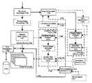
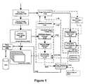
- FIG. 1shows the primary subsystems of a face tracking system in accordance with certain embodiments.
- FIGS. 2A and 2Billustrate an example of the same face under two different lighting conditions.
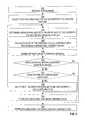
- FIG. 3is a flow diagram that illustrates an example of a ratio-based Haar-like feature value computation technique, according to an embodiment of the invention.
- FIG. 4shows a block diagram of a special purpose computing device for carrying out techniques of the present invention.
- a face-detection systeminstead of calculating a Haar-like feature value by subtracting the average pixel intensity value in one rectangular region from the average pixel intensity value in another, adjacent rectangular region, calculates that Haar-like feature value by dividing the average pixel intensity value in one such rectangular region by the average pixel intensity value in the other such adjacent rectangular region.
- each Haar-like valueis calculated as a ratio of average pixel intensity values rather than as a difference between such average pixel intensity values.
- the feature valuesmay be calculated using this ratio-based technique both during the machine-learning procedure, in which the numerical ranges for features in known face-containing images are learned based on labeled training data, and during the classifier-applying procedure, in which an unlabeled image's feature values are calculated and compared to the previously machine-learned numerical ranges.
- alternative techniquessuch as the statistical variance-based approach discussed previously, may still be during the machine-learning procedure; such alternative techniques still will produce numerical ranges that can be mathematically adapted to work in conjunction with feature values determined using the ratio-based feature value computation techniques disclosed herein.
- Various embodiments of the inventionalso include a digital image acquisition system, having no photographic film, comprising means for carrying out one or more steps of the methods described in this application.
- Alternative embodiments of the inventioninclude one or more machine-readable non-transitory storage media storing instructions which when executed by one or more computing devices cause the performance of one or more steps of the methods described in this application.
- ratio-based feature computation techniqueBefore aspects of the ratio-based feature computation technique are described in detail, a system in which the ratio-based feature computation technique may be implemented and used is discussed below.
- FIG. 1shows the primary subsystems of a face tracking system in accordance with certain embodiments.
- the solid linesindicate the flow of image data; the dashed lines indicate control inputs or information outputs (e.g. location(s) of detected faces) from a module.
- an image processing apparatuscan be a digital still camera (DSC), a video camera, a cell phone equipped with an image capturing mechanism or a hand help computer equipped with an internal or external camera, or a combination thereof.
- DSCdigital still camera
- a digital image, i(x, y),is acquired in raw format from an image sensor 105 such as a charged coupled device (CCD) sensor or complimentary metal oxide semiconductor (CMOS) sensor.
- An image subsampler 112generates a smaller copy of the main image.
- Most digital camerasalready contain dedicated hardware subsystems to perform image subsampling, for example to provide preview images to a camera display.
- the subsampled imageis provided in bitmap format (RGB or YCC).
- the normal image acquisition chainperforms post-processing on the raw image 110 which typically includes some luminance and color balancing.
- the subsamplingmay occur after such post-processing, or after certain post-processing filters are applied, but before the entire post-processing filter chain is completed.
- the subsampled imagemay be passed to an integral image generator 115 which creates an integral image from the subsampled image.
- the integral image, ii(x,y), at location (x, y)contains the sum of the pixel values above and to the left of point (x, y) from image i(x,y).
- integral image generator 115may be omitted from the system.
- This integral image, if generated (or the subsampled image, if the integral image is not generated)is next passed to a fixed size face detector 120 . If the integral image is generated, then the face detector is applied to the full integral image, but as this is an integral image of a subsampled copy of the main image, the processing involved in the face detection is proportionately reduced. If the subsampled image is 1 ⁇ 4 of the main image, e.g., has 1 ⁇ 4 the number of pixels and/or 1 ⁇ 4 the size, then the processing time involved is only about 25% of that for the full image. Alternatively, the face detector may be applied to the subsampled image under circumstances in which the integral image is not generated.
- This approachis particularly amenable to hardware embodiments where the subsampled image memory space can be scanned by a fixed size direct memory access (DMA) window and digital logic to implement a Haar-feature classifier chain can be applied to this DMA window.
- DMAdirect memory access
- Several sizes of classifiersmay alternatively be used (in a software embodiment), or multiple fixed-size classifiers may be used (in a hardware embodiment).
- any newly detected candidate face regions 141are passed onto a face tracking module 111 , where any face regions confirmed from previous analysis 145 may be merged with new candidate face regions prior to being provided 142 to a face tracker 290 .
- the face tracker 290provides a set of confirmed candidate regions 143 back to the tracking module 111 . Additional image processing filters are preferably applied by the tracking module 111 to confirm either that these confirmed regions 143 are face regions or to maintain regions as candidates if they have not been confirmed as such by the face tracker 290 .
- a final set of face regions 145can be output by the module 111 for use elsewhere in the camera or to be stored within or in association with an acquired image for later processing either within the camera or offline. Set 145 can also be used in a next iteration of face tracking.
- a full-size copy of the main image 130will normally reside in the system memory 140 of the image acquisition system. This may be accessed by a candidate region extractor 125 component of the face tracker 290 , which selects image patches based on candidate face region data 142 obtained from the face tracking module 111 .
- these image patches for each candidate regionare optionally passed to an integral image generator 115 , which passes the resulting integral images to a variable sized detector 121 —as one possible example a Viola-Jones detector—which then applies a classifier chain—preferably at least a 32-classifier chain—to the integral image (or subsampled image) for each candidate region across a range of different scales.
- the range of scales 144 employed by the face detector 121is determined and supplied by the face tracking module 111 and is based partly on statistical information relating to the history of the current candidate face regions 142 and partly on external metadata determined from other subsystems within the image acquisition system.
- the face detector 121is applied at this particular scale and/or perhaps at one scale higher (i.e. 1.25 times larger) and one scale lower (i.e. 1.25 times lower).
- the candidate face regionwill have a minimum size beyond which it should not decrease—this is in order to allow for localized movement of the camera by a user between frames. In some image acquisition systems which contain motion sensors, such localized movements may be tracked. This information may be employed to further improve the selection of scales and the size of candidate regions.
- the candidate region tracker 290provides a set of confirmed face regions 143 based on full variable size face detection of the image patches to the face tracking module 111 . Clearly, some candidate regions will have been confirmed while others will have been rejected, and these can be explicitly returned by the tracker 290 or can be calculated by the tracking module 111 by analyzing the difference between the confirmed regions 143 and the candidate regions 142 . In either case, the face tracking module 111 can then apply alternative tests to candidate regions rejected by the tracker 290 to determine whether these should be maintained as candidate regions 142 for the next cycle of tracking or whether these should indeed be removed from tracking.
- the module 111communicates with the sub-sampler 112 to determine when the next acquired image is to be sub-sampled, and so provided to the detector 280 , and also to provide the resolution 146 at which the next acquired image is to be sub-sampled.
- the candidate regions 142 provided to the extractor 125 for the next acquired imagewill be the regions 145 confirmed by the tracking module 111 from the last acquired image.
- these candidate regionsare preferably merged with the previous set of confirmed regions 145 to provide the set of candidate regions 142 to the extractor 125 for the next acquired image.
- Zoom informationmay be obtained from camera firmware. Using software techniques which analyze images in camera memory 140 or image store 150 , the degree of pan or tilt of the camera may be determined from one image to another.
- the acquisition deviceis provided with a motion sensor 180 , as illustrated at FIG. 1 , to determine the degree and direction of pan from one image to another, and avoiding the processing involved in determining camera movement in software.
- Such motion sensor for a digital cameramay be based on an accelerometer, and may be optionally based on gyroscopic principals within the camera, primarily for the purposes of warning or compensating for hand shake during main image capture.
- U.S. Pat. No. 4,448,510, to Murakoshiwhich is hereby incorporated by reference, discloses such a system for a conventional camera
- U.S. Pat. No. 6,747,690, to Molgaardwhich is also incorporated by reference, discloses accelerometer sensors applied within a modern digital camera.
- the accelerometermay incorporate a sensing module which generates a signal based on the acceleration experienced and an amplifier module which determines the range of accelerations which can effectively be measured.
- the accelerometermay allow software control of the amplifier stage which allows the sensitivity to be adjusted.
- the motion sensor 180could equally be implemented with MEMS sensors of the sort which will be incorporated in next generation consumer cameras and camera-phones.
- shake compensationwould typically not be used because image quality is lower.
- Thisprovides the opportunity to configure the motion sensor 180 to sense large movements by setting the motion sensor amplifier module to low gain.
- the size and direction of movement detected by the sensor 180is preferably provided to the face tracker 111 .
- the approximate size of faces being trackedis already known, and this enables an estimate of the distance of each face from the camera. Accordingly, knowing the approximate size of the large movement from the sensor 180 allows the approximate displacement of each candidate face region to be determined, even if they are at differing distances from the camera.
- the face tracker 111shifts the locations of candidate regions as a function of the direction and size of the movement.
- the size of the region over which the tracking algorithms are appliedmay also be enlarged (and the sophistication of the tracker may be decreased to compensate for scanning a larger image area) as a function of the direction and size of the movement.
- the amplifier gain of the motion sensor 180is returned to normal, allowing the main image acquisition chain 105 , 110 for full-sized images to employ normal shake compensation algorithms based on information from the motion sensor 180 .
- An alternative way of limiting the areas of an image to which the face detector 120 is to be appliedinvolves identifying areas of the image which include skin tones.
- U.S. Pat. No. 6,661,907which is hereby incorporated by reference, discloses one such technique for detecting skin tones and subsequently only applying face detection in regions having a predominant skin color.
- skin segmentation 190is preferably applied to a sub-sampled version of the acquired image. If the resolution of the sub-sampled version is not sufficient, then a previous image stored in image store 150 or a next sub-sampled image can be used as long as the two images are not too different in content from the current acquired image. Alternatively, skin segmentation 190 can be applied to the full size video image 130 .
- regions containing skin tonesare identified by bounding rectangles.
- the bounding rectanglesare optionally provided to the integral image generator 115 , which produces integral image patches corresponding to the rectangles in a manner similar to that used by the tracker integral image generator 115 .
- confirmed face regions 145are used to identify regions of a subsequently acquired sub-sampled image on which luminance correction may be performed to bring regions of interest of the image to be analyzed to the desired parameters.
- luminance correctionis to improve the luminance contrast within the regions of the sub-sampled image defined by confirmed face regions 145 .
- Contrast enhancementmay be used to increase local contrast of an image, especially when the usable data of the image is represented by close contrast values. Through this adjustment, intensities of pixels of a region when represented on a histogram, which would otherwise be closely distributed, can be better distributed. This allows for areas of lower local contrast to gain a higher contrast without affecting global contrast. Histogram equalization accomplishes this by effectively spreading out the most frequent intensity values.
- the methodis useful in images with backgrounds and foregrounds that are both bright or both dark.
- the methodcan lead to better detail in photographs that are over-exposed or under-exposed.
- this luminance correctioncan be included in the computation of an “adjusted” integral image in the generators 115 .
- no integral imageis generated or stored.
- the camera applicationwhen face detection is being used, is set to dynamically modify the exposure from the computed default to a higher values (from frame to frame, slightly overexposing the scene) until the face detection provides a lock onto a face.
- face detection algorithmstypically employ methods or use classifiers to detect faces in a picture at different orientations: 0, 90, 180 and 270 degrees.
- the cameramay be equipped with an orientation sensor 170 , as illustrated at FIG. 1 .
- Thiscan include a hardware sensor for determining whether the camera is being held upright, inverted or tilted clockwise or counter-clockwise.
- the orientation sensorcan comprise an image analysis module connected either to the image acquisition hardware 105 , 110 or camera memory 140 or image store 150 for quickly determining whether images are being acquired in portrait or landscape mode and whether the camera is tilted clockwise or counter-clockwise.
- the camera orientationcan be fed to one or both of the face detectors 120 , 121 .
- the detectorsmay apply face detection according to the likely orientation of faces in an image acquired with the determined camera orientation. This feature can either significantly reduce the face detection processing overhead, for example, by avoiding the employment of classifiers which are unlikely to detect faces, or increase its accuracy by running classifiers more likely to detects faces in a given orientation more often.
- FIG. 3is a flow diagram that illustrates an example of a ratio-based Haar-like feature value computation technique, according to an embodiment of the invention.
- Alternative embodiments of the inventionmay involve fewer, more, or different steps than those illustrated in FIG. 3 .
- the technique illustrated in FIG. 3begins with the assumption that a machine-learning mechanism has already evaluated a set of training data and automatically determined, for each Haar-like feature in a set of Haar-like features, a normalized numerical range corresponding to that feature; thus, the illustrated technique involves the determination of whether an unlabeled image's feature values, calculated based on ratios, fall within those numerical ranges. Additional optional enhancements to the technique illustrated in FIG. 3 will be described afterward.
- a source imageis produced.
- a digital cameramay capture an image through a system of lenses and sensors.
- the digital cameramay store this image in memory as an array of pixels.
- Each such pixelmay have a set of hue component values, such as red, green, and blue values, and an intensity value which generally indicates the brightness of that pixel regardless of its hue.
- a first Haar-like feature in a list of Haar-like featuresis selected to be the currently calculated feature.
- the first Haar-like featuremight be the two-rectangle feature shown as adjacent rectangles 206 and 208 in FIG. 2A . This is the first feature of several features for which values will be determined.
- Other features in the list of featuresmay include adjacent rectangles of different quantities, sizes, dimensions, and positions within the source image.
- the features in the listmay be ordered based on the order in which classifiers corresponding to those features occur in the previously generated classifier chain, such that the first feature in the list is the feature that is evaluated by the first classifier in the classifier chain, and so on.
- the quantity of features in the listmay correspond to the quantity of classifiers in the classifier chain.
- the average pixel intensity values of each of the currently calculated feature's rectanglesare determined.
- such a rectangle's average pixel intensity valueis calculated by summing the intensity values of each of the source image's pixels that occurs within that rectangle, and then dividing that sum by the quantity of those pixels contained within the rectangle.
- a rectangle's average pixel intensity valuemay be calculated based on an integral image that was generated for the source image; however, in one embodiment of the invention, no integral image is generated or stored.
- the number of average pixel intensity values calculated in block 306depends on the quantity of rectangles in the currently calculated feature.
- the currently calculated featuremight be a two-rectangle, three-rectangle, or four-rectangle feature.
- a ratio of the average intensity values determined in block 306is calculated. If the currently calculated feature is a two-rectangle feature, then the ratio is determined by dividing the average pixel intensity value of one of the feature's rectangles (e.g., the left rectangle) by the average pixel intensity value of the other of the feature's rectangles (e.g., the right rectangle). If the currently calculated feature is a three-rectangle feature, then the ratio is determined by dividing the average pixel intensity value of the feature's center rectangle by the sum of the average pixel intensity values of the feature's two outer rectangles.
- the ratiois determined by dividing (a) the sum of one of the feature's quadrant pairs' (e.g., the quadrant pair consisting of the feature's upper-left and lower-right rectangles) average pixel intensity values by (b) the sum of the other of the feature's quadrant pairs' (e.g., the quadrant pair consisting of the feature's upper-right and lower-left rectangles) average pixel intensity values.
- the ratiois calculated by dividing one average pixel intensity value (or sum of two such values) by another average pixel intensity value (or sum of two such values).
- the ratiois instead calculated by multiplying one average pixel intensity value by a reciprocal value located in a pre-generated look-up table.
- the result of the ratio calculated in block 308is normalized mathematically.
- the value produced by the ratio's divisionmay be normalized such that the value lies somewhere within the range of 0 to 64. This may be accomplished, for example, by multiplying the value (which will be some number between 0 and 1) by 64. This normalized value essentially is the currently calculated feature's value.
- LCDliquid crystal display
- the ratio of a feature's rectangles' average pixel intensity valuesis instead calculated by multiplying one average pixel intensity value by a reciprocal value located in a pre-generated look-up table.
- the real-time (i.e., post-image capture) division of such rectangles' average pixel intensity valuesis avoided in the calculation of the ratio.
- a look-up tablewhich correlates discrete values (e.g., integer values) within a specified range (e.g., 0 to 255) to associated reciprocal values, is generated and stored.
- the look-up tableonly needs to be generated and stored once, but can be used multiple times.
- pixel intensity valuesare integer values that fall within the range of 0 to 255.
- the average pixel intensity value of any of a feature's rectanglesnecessarily also will fall within this range of 0 to 255; an average cannot be higher than the highest value or lower than the lowest value.
- the look-up tablecontains an entry that associates that key integer value with a reciprocal value that is equal to 2 19 divided by that key integer value.
- the entry for the key integer value 1is associated with a reciprocal value of 524288 (2 19 /1), while the entry for the key integer value 255 is associated with a reciprocal value of approximately 2056 (2 19 /255).
- the entry for the key integer value 0associates that key integer value with the reciprocal value 524288 (2 19 /1), since division by zero is undefined.
- the first average pixel intensity valueis multiplied by the reciprocal value that is associated, in the look-up table, with the key integer value to which the second average pixel intensity value is closest (for purposes of simplicity, truncation of any decimal part of the second average may be performed to determine the key integer value to look up in the look-up table).
- the product of the multiplicationwhich will be a value in the range of 0 to 2 20 , then may be normalized to be somewhere with the range of 0 to 64, as is discussed above in connection with block 310 . This normalized value essentially is the currently calculated feature's value.
- the techniques described hereinare implemented by one or more special-purpose computing devices.
- the special-purpose computing devicescan be incorporated into the digital image acquisition device described in FIG. 1 or might be separate from the digital image acquisition described in FIG. 1 .
- the special-purpose computing devicesmay be hard-wired to perform the techniques, or may include digital electronic devices such as one or more application-specific integrated circuits (ASICs) or field programmable gate arrays (FPGAs) that are persistently programmed to perform the techniques, or may include one or more general purpose hardware processors programmed to perform the techniques pursuant to program instructions in firmware, memory, other storage, or a combination. Such special-purpose computing devices may also combine custom hard-wired logic, ASICs, or FPGAs with custom programming to accomplish the techniques.
- the special-purpose computing devicesmay be desktop computer systems, portable computer systems, handheld devices, networking devices or any other device that incorporates hard-wired and/or program logic to implement the techniques.
- FIG. 4is a block diagram that illustrates a computer system 400 upon which an embodiment of the invention may be implemented.
- Computer system 400includes a bus 402 or other communication mechanism for communicating information, and a hardware processor 404 coupled with bus 402 for processing information.
- Hardware processor 404may be, for example, a general purpose microprocessor.
- Computer system 400also includes a main memory 406 , such as a random access memory (RAM) or other dynamic storage device, coupled to bus 402 for storing information and instructions to be executed by processor 404 .
- Main memory 406also may be used for storing temporary variables or other intermediate information during execution of instructions to be executed by processor 404 .
- Such instructionswhen stored in storage media accessible to processor 404 , render computer system 400 into a special-purpose machine that is customized to perform the operations specified in the instructions.
- Computer system 400further includes a read only memory (ROM) 408 or other static storage device coupled to bus 402 for storing static information and instructions for processor 404 .
- ROMread only memory
- a storage device 410such as a magnetic disk or optical disk, is provided and coupled to bus 402 for storing information and instructions.
- Computer system 400may be coupled via bus 402 to a display 412 , such as a cathode ray tube (CRT), for displaying information to a computer user.
- a display 412such as a cathode ray tube (CRT)
- An input device 414is coupled to bus 402 for communicating information and command selections to processor 404 .
- cursor control 416is Another type of user input device
- cursor control 416such as a mouse, a trackball, or cursor direction keys for communicating direction information and command selections to processor 404 and for controlling cursor movement on display 412 .
- This input devicetypically has two degrees of freedom in two axes, a first axis (e.g., x) and a second axis (e.g., y), that allows the device to specify positions in a plane.
- Computer system 400may implement the techniques described herein using customized hard-wired logic, one or more ASICs or FPGAs, firmware and/or program logic which in combination with the computer system causes or programs computer system 400 to be a special-purpose machine. According to one embodiment, the techniques herein are performed by computer system 400 in response to processor 404 executing one or more sequences of one or more instructions contained in main memory 406 . Such instructions may be read into main memory 406 from another storage medium, such as storage device 410 . Execution of the sequences of instructions contained in main memory 406 causes processor 404 to perform the process steps described herein. In alternative embodiments, hard-wired circuitry may be used in place of or in combination with software instructions.
- Non-volatile, non-transitory mediaincludes, for example, optical or magnetic disks, such as storage device 410 .
- Volatile mediaincludes dynamic memory, such as main memory 406 .
- non-transitory storage mediainclude, for example, a floppy disk, a flexible disk, hard disk, solid state drive, magnetic tape, or any other magnetic data storage medium, a CD-ROM, any other optical data storage medium, any physical medium with patterns of holes, a RAM, a PROM, and EPROM, a FLASH-EPROM, NVRAM, any other memory chip or cartridge.
- Non-transitory storage mediais distinct from but may be used in conjunction with transmission media.
- Transmission mediaparticipates in transferring information between storage media.
- transmission mediaincludes coaxial cables, copper wire and fiber optics, including the wires that comprise bus 402 .
- transmission mediacan also take the form of acoustic or light waves, such as those generated during radio-wave and infra-red data communications.
- Various forms of mediamay be involved in carrying one or more sequences of one or more instructions to processor 404 for execution.
- the instructionsmay initially be carried on a magnetic disk or solid state drive of a remote computer.
- the remote computercan load the instructions into its dynamic memory and send the instructions over a telephone line using a modem.
- a modem local to computer system 400can receive the data on the telephone line and use an infra-red transmitter to convert the data to an infra-red signal.
- An infra-red detectorcan receive the data carried in the infra-red signal and appropriate circuitry can place the data on bus 402 .
- Bus 402carries the data to main memory 406 , from which processor 404 retrieves and executes the instructions.
- the instructions received by main memory 406may optionally be stored on storage device 410 either before or after execution by processor 404 .
- Computer system 400also includes a communication interface 418 coupled to bus 402 .
- Communication interface 418provides a two-way data communication coupling to a network link 420 that is connected to a local network 422 .
- communication interface 418may be an integrated services digital network (ISDN) card, cable modem, satellite modem, or a modem to provide a data communication connection to a corresponding type of telephone line.
- ISDNintegrated services digital network
- communication interface 418may be a local area network (LAN) card to provide a data communication connection to a compatible LAN.
- LANlocal area network
- Wireless linksmay also be implemented.
- communication interface 418sends and receives electrical, electromagnetic or optical signals that carry digital data streams representing various types of information.
- Network link 420typically provides data communication through one or more networks to other data devices.
- network link 420may provide a connection through local network 422 to a host computer 424 or to data equipment operated by an Internet Service Provider (ISP) 426 .
- ISP 426in turn provides data communication services through the world wide packet data communication network now commonly referred to as the “Internet” 428 .
- Internet 428uses electrical, electromagnetic or optical signals that carry digital data streams.
- the signals through the various networks and the signals on network link 420 and through communication interface 418which carry the digital data to and from computer system 400 , are example forms of transmission media.
- Computer system 400can send messages and receive data, including program code, through the network(s), network link 420 and communication interface 418 .
- a server 430might transmit a requested code for an application program through Internet 428 , ISP 426 , local network 422 and communication interface 418 .
- the received codemay be executed by processor 404 as it is received, and/or stored in storage device 410 , or other non-volatile storage for later execution.
Landscapes
- Engineering & Computer Science (AREA)
- Physics & Mathematics (AREA)
- General Physics & Mathematics (AREA)
- Multimedia (AREA)
- Theoretical Computer Science (AREA)
- Health & Medical Sciences (AREA)
- General Health & Medical Sciences (AREA)
- Oral & Maxillofacial Surgery (AREA)
- Human Computer Interaction (AREA)
- Image Analysis (AREA)
Abstract
Description
where ii(x,y) is the integral image, and i(x,y) is the source image.
Claims (24)
Priority Applications (1)
| Application Number | Priority Date | Filing Date | Title |
|---|---|---|---|
| US14/069,097US8977056B2 (en) | 2010-07-26 | 2013-10-31 | Face detection using division-generated Haar-like features for illumination invariance |
Applications Claiming Priority (2)
| Application Number | Priority Date | Filing Date | Title |
|---|---|---|---|
| US12/843,805US8971628B2 (en) | 2010-07-26 | 2010-07-26 | Face detection using division-generated haar-like features for illumination invariance |
| US14/069,097US8977056B2 (en) | 2010-07-26 | 2013-10-31 | Face detection using division-generated Haar-like features for illumination invariance |
Related Parent Applications (1)
| Application Number | Title | Priority Date | Filing Date |
|---|---|---|---|
| US12/843,805ContinuationUS8971628B2 (en) | 2010-07-26 | 2010-07-26 | Face detection using division-generated haar-like features for illumination invariance |
Publications (2)
| Publication Number | Publication Date |
|---|---|
| US20140056527A1 US20140056527A1 (en) | 2014-02-27 |
| US8977056B2true US8977056B2 (en) | 2015-03-10 |
Family
ID=45493299
Family Applications (2)
| Application Number | Title | Priority Date | Filing Date |
|---|---|---|---|
| US12/843,805Active2032-02-26US8971628B2 (en) | 2010-07-26 | 2010-07-26 | Face detection using division-generated haar-like features for illumination invariance |
| US14/069,097ActiveUS8977056B2 (en) | 2010-07-26 | 2013-10-31 | Face detection using division-generated Haar-like features for illumination invariance |
Family Applications Before (1)
| Application Number | Title | Priority Date | Filing Date |
|---|---|---|---|
| US12/843,805Active2032-02-26US8971628B2 (en) | 2010-07-26 | 2010-07-26 | Face detection using division-generated haar-like features for illumination invariance |
Country Status (1)
| Country | Link |
|---|---|
| US (2) | US8971628B2 (en) |
Cited By (1)
| Publication number | Priority date | Publication date | Assignee | Title |
|---|---|---|---|---|
| US10540697B2 (en) | 2017-06-23 | 2020-01-21 | Perfect365 Technology Company Ltd. | Method and system for a styling platform |
Families Citing this family (22)
| Publication number | Priority date | Publication date | Assignee | Title |
|---|---|---|---|---|
| US7844076B2 (en) | 2003-06-26 | 2010-11-30 | Fotonation Vision Limited | Digital image processing using face detection and skin tone information |
| CN102027505A (en) | 2008-07-30 | 2011-04-20 | 泰塞拉技术爱尔兰公司 | Automatic face and skin retouching using face detection |
| US8520089B2 (en)* | 2008-07-30 | 2013-08-27 | DigitalOptics Corporation Europe Limited | Eye beautification |
| JP5456159B2 (en)* | 2009-05-29 | 2014-03-26 | デジタルオプティックス・コーポレイション・ヨーロッパ・リミテッド | Method and apparatus for separating the top of the foreground from the background |
| US8605955B2 (en)* | 2009-06-29 | 2013-12-10 | DigitalOptics Corporation Europe Limited | Methods and apparatuses for half-face detection |
| US8379917B2 (en) | 2009-10-02 | 2013-02-19 | DigitalOptics Corporation Europe Limited | Face recognition performance using additional image features |
| US8971628B2 (en) | 2010-07-26 | 2015-03-03 | Fotonation Limited | Face detection using division-generated haar-like features for illumination invariance |
| KR20120072009A (en)* | 2010-12-23 | 2012-07-03 | 한국전자통신연구원 | Interaction recognition apparatus for multiple user and method thereof |
| KR20140013142A (en)* | 2012-07-18 | 2014-02-05 | 삼성전자주식회사 | Target detecting method of detecting target on image and image processing device |
| US9171226B2 (en)* | 2012-09-26 | 2015-10-27 | Carnegie Mellon University | Image matching using subspace-based discrete transform encoded local binary patterns |
| US10694106B2 (en)* | 2013-06-14 | 2020-06-23 | Qualcomm Incorporated | Computer vision application processing |
| US9413784B2 (en) | 2013-09-06 | 2016-08-09 | Microsoft Technology Licensing, Llc | World-driven access control |
| US9355268B2 (en)* | 2013-09-06 | 2016-05-31 | Microsoft Technology Licensing, Llc | Managing access by applications to perceptual information |
| US9424239B2 (en) | 2013-09-06 | 2016-08-23 | Microsoft Technology Licensing, Llc | Managing shared state information produced by applications |
| US9697365B2 (en) | 2013-09-06 | 2017-07-04 | Microsoft Technology Licensing, Llc | World-driven access control using trusted certificates |
| CN104240232B (en)* | 2014-07-16 | 2017-09-22 | 电子科技大学 | A kind of road damage inspection optimization method based on image procossing |
| US20240393883A1 (en)* | 2024-07-13 | 2024-11-28 | Maximilian Ralph Peter von und zu Liechtenstein | Wink Gesture Control System |
| US12093467B2 (en)* | 2023-01-13 | 2024-09-17 | Maximilian Ralph Peter von und zu Liechtenstein | Wink gesture control system |
| US9986289B2 (en)* | 2015-03-02 | 2018-05-29 | The Nielsen Company (Us), Llc | Methods and apparatus to count people |
| KR102407624B1 (en)* | 2015-10-06 | 2022-06-10 | 삼성전자주식회사 | Method for processing image of electronic device and electronic device thereof |
| KR102806686B1 (en)* | 2017-02-09 | 2025-05-16 | 한국전자통신연구원 | Apparatus and method for Object of Interest-centric Best-view Generation in Multi-camera Video |
| CN107315993A (en)* | 2017-05-10 | 2017-11-03 | 苏州天平先进数字科技有限公司 | A kind of peephole system and its face identification method based on recognition of face |
Citations (130)
| Publication number | Priority date | Publication date | Assignee | Title |
|---|---|---|---|---|
| US4299464A (en) | 1980-08-04 | 1981-11-10 | Eastman Kodak Company | Method and apparatus for reducing the incidence of eye closures during photographing of a human subject |
| US4448510A (en) | 1981-10-23 | 1984-05-15 | Fuji Photo Film Co., Ltd. | Camera shake detection apparatus |
| US5432863A (en) | 1993-07-19 | 1995-07-11 | Eastman Kodak Company | Automated detection and correction of eye color defects due to flash illumination |
| US5500671A (en) | 1994-10-25 | 1996-03-19 | At&T Corp. | Video conference system and method of providing parallax correction and a sense of presence |
| US5751836A (en) | 1994-09-02 | 1998-05-12 | David Sarnoff Research Center Inc. | Automated, non-invasive iris recognition system and method |
| US5802220A (en) | 1995-12-15 | 1998-09-01 | Xerox Corporation | Apparatus and method for tracking facial motion through a sequence of images |
| JPH10233929A (en) | 1997-02-19 | 1998-09-02 | Canon Inc | Image processing apparatus and method |
| US5805720A (en) | 1995-07-28 | 1998-09-08 | Mitsubishi Denki Kabushiki Kaisha | Facial image processing system |
| US6072903A (en) | 1997-01-07 | 2000-06-06 | Kabushiki Kaisha Toshiba | Image processing apparatus and image processing method |
| JP2000305141A (en) | 1999-04-21 | 2000-11-02 | Olympus Optical Co Ltd | Electronic camera |
| US6198505B1 (en) | 1999-07-19 | 2001-03-06 | Lockheed Martin Corp. | High resolution, high speed digital camera |
| US6246790B1 (en) | 1997-12-29 | 2001-06-12 | Cornell Research Foundation, Inc. | Image indexing using color correlograms |
| US20010012063A1 (en) | 2000-02-08 | 2001-08-09 | Masamine Maeda | Image pickup apparatus |
| JP2001216518A (en) | 2000-02-07 | 2001-08-10 | Fuji Photo Film Co Ltd | Method and device for matching and recording medium |
| US6278491B1 (en) | 1998-01-29 | 2001-08-21 | Hewlett-Packard Company | Apparatus and a method for automatically detecting and reducing red-eye in a digital image |
| EP1128316A1 (en) | 2000-02-28 | 2001-08-29 | Eastman Kodak Company | Face detecting and recognition camera and method |
| JP2001283224A (en) | 2000-03-31 | 2001-10-12 | Nec Corp | Face collating method, recording medium stored with the collating method and face collator |
| US20010038714A1 (en) | 2000-04-25 | 2001-11-08 | Daiki Masumoto | Picture recognition apparatus and method |
| US6335990B1 (en) | 1997-07-03 | 2002-01-01 | Cisco Technology, Inc. | System and method for spatial temporal-filtering for improving compressed digital video |
| US20020034337A1 (en) | 2000-05-23 | 2002-03-21 | Shekter Jonathan Martin | System for manipulating noise in digital images |
| US6407777B1 (en) | 1997-10-09 | 2002-06-18 | Deluca Michael Joseph | Red-eye filter method and apparatus |
| US20020080261A1 (en) | 2000-09-05 | 2002-06-27 | Minolta Co., Ltd. | Image processing apparatus and image sensing device |
| US20020102024A1 (en) | 2000-11-29 | 2002-08-01 | Compaq Information Technologies Group, L.P. | Method and system for object detection in digital images |
| US6456737B1 (en) | 1997-04-15 | 2002-09-24 | Interval Research Corporation | Data processing system and method |
| US20020136450A1 (en) | 2001-02-13 | 2002-09-26 | Tong-Xian Chen | Red-eye detection based on red region detection with eye confirmation |
| US20020154793A1 (en) | 2001-03-05 | 2002-10-24 | Robert Hillhouse | Method and system for adaptively varying templates to accommodate changes in biometric information |
| JP2003018398A (en) | 2001-04-20 | 2003-01-17 | Mitsubishi Electric Research Laboratories Inc | Method for generating a super-resolution image from pixel image |
| US20030044070A1 (en) | 2001-09-03 | 2003-03-06 | Manfred Fuersich | Method for the automatic detection of red-eye defects in photographic image data |
| EP1296510A2 (en) | 2001-09-20 | 2003-03-26 | Eastman Kodak Company | System and method for correcting defects in captured images |
| JP2003111041A (en) | 2001-09-28 | 2003-04-11 | Canon Inc | Image processing apparatus, image processing system, image processing method, storage medium, and program |
| US20030071908A1 (en) | 2001-09-18 | 2003-04-17 | Masato Sannoh | Image pickup device, automatic focusing method, automatic exposure method, electronic flash control method and computer program |
| US20030086134A1 (en) | 2001-09-27 | 2003-05-08 | Fuji Photo Film Co., Ltd. | Apparatus and method for image processing |
| US20030118218A1 (en) | 2001-02-16 | 2003-06-26 | Barry Wendt | Image identification system |
| JP2003179807A (en) | 2001-12-13 | 2003-06-27 | Fuji Photo Film Co Ltd | Image pickup device |
| JP2003187233A (en) | 2001-09-03 | 2003-07-04 | Agfa Gevaert Ag | Method for automatically detecting red-eye defect in photographic image data |
| US20030138143A1 (en) | 1998-08-09 | 2003-07-24 | Takafumi Noguchi | Method and apparatus for correcting the density and color of an image and storage medium having a program for executing the image correction |
| JP2003274271A (en) | 2002-03-18 | 2003-09-26 | Fuji Photo Film Co Ltd | Image photographing method, image outputting method and camera |
| US20030184671A1 (en) | 2002-03-28 | 2003-10-02 | Robins Mark N. | Glare reduction system for image capture devices |
| US6636694B1 (en) | 1999-09-14 | 2003-10-21 | Kabushiki Kaisha Toshiba | Face image photographing apparatus and face image photographing method |
| US6661907B2 (en) | 1998-06-10 | 2003-12-09 | Canon Kabushiki Kaisha | Face detection in digital images |
| JP2004005694A (en) | 2002-05-29 | 2004-01-08 | Eastman Kodak Co | Image processing method, digital image processor, digital camera, digital photograph finishing system, and program |
| JP2004023518A (en) | 2002-06-18 | 2004-01-22 | Olympus Corp | Imaging device |
| US20040042659A1 (en) | 2002-08-30 | 2004-03-04 | Guo Jinhong Katherine | Method for texture-based color document segmentation |
| KR20040034342A (en) | 2002-10-15 | 2004-04-28 | 삼성전자주식회사 | Method and apparatus for extracting feature vector for use in face recognition and retrieval |
| US6747690B2 (en) | 2000-07-11 | 2004-06-08 | Phase One A/S | Digital camera with integrated accelerometers |
| US20040213478A1 (en) | 2001-05-02 | 2004-10-28 | Vyacheslav Chesnokov | Image enhancement methods and apparatus therefor |
| US6823086B1 (en) | 2000-08-29 | 2004-11-23 | Analogic Corporation | Adaptive spatial filter |
| US20040264780A1 (en) | 2003-06-30 | 2004-12-30 | Lei Zhang | Face annotation for photo management |
| US20050013506A1 (en) | 2003-07-18 | 2005-01-20 | Canon Kabushiki Kaisha | Image processing method and apparatus |
| JP2005078158A (en) | 2003-08-28 | 2005-03-24 | Dainippon Printing Co Ltd | Image processing apparatus, image processing method, program, and recording medium |
| KR20050041772A (en) | 2003-10-31 | 2005-05-04 | 삼성전자주식회사 | Face detection method and apparatus and security system employing the same |
| JP2005164475A (en) | 2003-12-04 | 2005-06-23 | Mitsutoyo Corp | Measuring apparatus for perpendicularity |
| JP2005165984A (en) | 2003-12-05 | 2005-06-23 | Seiko Epson Corp | Human face top detection method, head top detection system, and head top detection program |
| JP2005208760A (en) | 2004-01-20 | 2005-08-04 | Fujitsu Ltd | Person image extraction apparatus and computer program |
| WO2005076217A2 (en) | 2004-02-04 | 2005-08-18 | Fotonation Vision Limited | Optimized red-eye filter method and apparatus involving subsample representations of selected image regions |
| US20050226509A1 (en) | 2004-03-30 | 2005-10-13 | Thomas Maurer | Efficient classification of three dimensional face models for human identification and other applications |
| US20050226484A1 (en) | 2004-03-31 | 2005-10-13 | Basu Samit K | Method and apparatus for efficient calculation and use of reconstructed pixel variance in tomography images |
| US20050249416A1 (en) | 2004-05-07 | 2005-11-10 | General Electric Company | Contraband detection system and method using variance data |
| US20050259185A1 (en) | 2004-05-21 | 2005-11-24 | Moon-Cheol Kim | Gamma correction apparatus and method capable of preventing noise boost-up |
| KR20060003666A (en) | 2004-07-07 | 2006-01-11 | 삼성전자주식회사 | Method and device for determining image correspondence for face recognition, Image correction method and device for achieving this |
| US20060039690A1 (en) | 2004-08-16 | 2006-02-23 | Eran Steinberg | Foreground/background segmentation in digital images with differential exposure calculations |
| JP2006072770A (en) | 2004-09-02 | 2006-03-16 | Sanyo Electric Co Ltd | Face detection device and face direction estimation device |
| US20060072815A1 (en) | 2004-10-04 | 2006-04-06 | Donghui Wu | Enhanced automatic red eye removal |
| US20060110014A1 (en) | 2002-12-13 | 2006-05-25 | Koninklijke Philips Electronics, N.V. | Expression invariant face recognition |
| US7072525B1 (en) | 2001-02-16 | 2006-07-04 | Yesvideo, Inc. | Adaptive filtering of visual image using auxiliary image information |
| US20060204052A1 (en) | 2005-03-11 | 2006-09-14 | Fuji Photo Film Co., Ltd. | Method, apparatus, and program for detecting red eye |
| JP2006259974A (en) | 2005-03-16 | 2006-09-28 | Fuji Photo Film Co Ltd | Image-processing method and device |
| US7130453B2 (en) | 2000-08-09 | 2006-10-31 | Matsushita Electric Industrial Co., Ltd. | Eye position detection method and device |
| US20060257047A1 (en) | 2005-05-11 | 2006-11-16 | Fuji Photo Film Co., Ltd. | Image processing apparatus, image processing method, and image processing program |
| JP2006319870A (en) | 2005-05-16 | 2006-11-24 | Fujifilm Holdings Corp | Photographic device, method and program |
| JP2006319534A (en) | 2005-05-11 | 2006-11-24 | Fuji Photo Film Co Ltd | Imaging apparatus, method, and program |
| US20060280380A1 (en) | 2005-06-14 | 2006-12-14 | Fuji Photo Film Co., Ltd. | Apparatus, method, and program for image processing |
| US20060285754A1 (en) | 2004-08-16 | 2006-12-21 | Eran Steinberg | Indoor/Outdoor Classification in Digital Images |
| US20060291739A1 (en) | 2005-06-24 | 2006-12-28 | Fuji Photo Film Co., Ltd. | Apparatus, method and program for image processing |
| EP1748378A1 (en) | 2005-07-26 | 2007-01-31 | Canon Kabushiki Kaisha | Image capturing apparatus and image capturing method |
| US7176975B2 (en) | 2001-06-19 | 2007-02-13 | Casio Computer Co., Ltd. | Image pick-up apparatus, image pick-up method, and storage medium that records image pick-up method program |
| US20070036429A1 (en) | 2005-08-09 | 2007-02-15 | Fuji Photo Film Co., Ltd. | Method, apparatus, and program for object detection in digital image |
| WO2007060980A1 (en) | 2005-11-25 | 2007-05-31 | Nikon Corporation | Electronic camera and image processing device |
| US20070147820A1 (en) | 2005-12-27 | 2007-06-28 | Eran Steinberg | Digital image acquisition system with portrait mode |
| US20070172126A1 (en) | 2006-01-23 | 2007-07-26 | Fujifilm Corporation | Face detection method, device and program |
| US20070177817A1 (en) | 2006-01-27 | 2007-08-02 | Microsoft Corporation | Region-based image denoising |
| US20070189609A1 (en) | 2005-03-31 | 2007-08-16 | Fuji Photo Film Co., Ltd. | Method, apparatus, and program for discriminating faces |
| US20070196019A1 (en) | 2006-02-23 | 2007-08-23 | Fujifilm Corporation | Method, apparatus, and program for judging faces facing specific directions |
| US20070195996A1 (en) | 2006-02-22 | 2007-08-23 | Fujifilm Corporation | Characteristic point detection method, apparatus, and program |
| WO2007097777A1 (en) | 2006-02-24 | 2007-08-30 | Fotonation Vision Limited | Method and apparatus for selective disqualification of digital images |
| WO2007106117A2 (en) | 2006-02-24 | 2007-09-20 | Fotonation Vision Limited | Method and apparatus for selective rejection of digital images |
| JP2007241424A (en) | 2006-03-06 | 2007-09-20 | Seiko Epson Corp | Image processing apparatus and image processing method |
| US20070216777A1 (en) | 2006-03-17 | 2007-09-20 | Shuxue Quan | Systems, methods, and apparatus for exposure control |
| US20070263119A1 (en) | 2006-05-15 | 2007-11-15 | Microsoft Corporation | Object matting using flash and no-flash images |
| US20070263928A1 (en) | 2006-05-15 | 2007-11-15 | Fujifilm Corporation | Method, apparatus, and program for processing red eyes |
| EP1858255A1 (en) | 2005-03-10 | 2007-11-21 | Fuji Photo Film Co., Ltd. | Background replacement device, background replacement program, and background replacement method |
| US20070269108A1 (en) | 2006-05-03 | 2007-11-22 | Fotonation Vision Limited | Foreground / Background Separation in Digital Images |
| US7315631B1 (en) | 2006-08-11 | 2008-01-01 | Fotonation Vision Limited | Real-time face tracking in a digital image acquisition device |
| JP2008005081A (en) | 2006-06-21 | 2008-01-10 | Mitsubishi Electric Corp | Authentication device |
| US20080025576A1 (en) | 2006-07-25 | 2008-01-31 | Arcsoft, Inc. | Method for detecting facial expressions of a portrait photo by an image capturing electronic device |
| US7352394B1 (en) | 1997-10-09 | 2008-04-01 | Fotonation Vision Limited | Image modification based on red-eye filter analysis |
| US20080112599A1 (en) | 2006-11-10 | 2008-05-15 | Fotonation Vision Limited | method of detecting redeye in a digital image |
| US7403643B2 (en) | 2006-08-11 | 2008-07-22 | Fotonation Vision Limited | Real-time face tracking in a digital image acquisition device |
| US20080205712A1 (en) | 2007-02-28 | 2008-08-28 | Fotonation Vision Limited | Separating Directional Lighting Variability in Statistical Face Modelling Based on Texture Space Decomposition |
| US20080219517A1 (en) | 2007-03-05 | 2008-09-11 | Fotonation Vision Limited | Illumination Detection Using Classifier Chains |
| US20080253651A1 (en) | 2006-12-22 | 2008-10-16 | Canon Kabushiki Kaisha | Image processing apparatus and method thereof |
| US20080310759A1 (en) | 2007-06-12 | 2008-12-18 | General Electric Company | Generic face alignment via boosting |
| US20080309617A1 (en) | 2007-06-15 | 2008-12-18 | Microsoft Corporation | Graphical communication user interface |
| US20090080795A1 (en) | 2003-07-18 | 2009-03-26 | Canon Kabushiki Kaisha | Image processing apparatus and method |
| US20090087099A1 (en) | 2007-09-28 | 2009-04-02 | Fujifilm Corporation | Image processing apparatus, image capturing apparatus, image processing method and recording medium |
| US7551755B1 (en) | 2004-01-22 | 2009-06-23 | Fotonation Vision Limited | Classification and organization of consumer digital images using workflow, and face detection and recognition |
| US20090185753A1 (en) | 2008-01-18 | 2009-07-23 | Fotonation Ireland Limited | Image processing method and apparatus |
| US7567707B2 (en) | 2005-12-20 | 2009-07-28 | Xerox Corporation | Red eye detection and correction |
| US20090190803A1 (en) | 2008-01-29 | 2009-07-30 | Fotonation Ireland Limited | Detecting facial expressions in digital images |
| US20090297044A1 (en) | 2008-05-15 | 2009-12-03 | Nikon Corporation | Image processing apparatus, method of image processing, processing apparatus, method of processing, and recording medium |
| US7630006B2 (en) | 1997-10-09 | 2009-12-08 | Fotonation Ireland Limited | Detecting red eye filter and apparatus using meta-data |
| US20090303342A1 (en) | 2006-08-11 | 2009-12-10 | Fotonation Ireland Limited | Face tracking for controlling imaging parameters |
| US20100053362A1 (en) | 2003-08-05 | 2010-03-04 | Fotonation Ireland Limited | Partial face detector red-eye filter method and apparatus |
| US20100054592A1 (en) | 2004-10-28 | 2010-03-04 | Fotonation Ireland Limited | Analyzing partial face regions for red-eye detection in acquired digital images |
| US20100053367A1 (en) | 2003-08-05 | 2010-03-04 | Fotonation Ireland Limited | Partial face tracker for red-eye filter method and apparatus |
| US20100053368A1 (en) | 2003-08-05 | 2010-03-04 | Fotonation Ireland Limited | Face tracker and partial face tracker for red-eye filter method and apparatus |
| US7783085B2 (en) | 2006-05-10 | 2010-08-24 | Aol Inc. | Using relevance feedback in face recognition |
| US7804983B2 (en) | 2006-02-24 | 2010-09-28 | Fotonation Vision Limited | Digital image acquisition control and correction method and apparatus |
| WO2010136593A2 (en) | 2009-05-29 | 2010-12-02 | Tessera Technologies Ireland Limited | Methods and apparatuses for foreground, top-of-the-head separation from background |
| WO2011000841A1 (en) | 2009-06-29 | 2011-01-06 | Tessera Technologies Ireland Limited | Methods and apparatuses for half-face detection |
| US20110044553A1 (en) | 2008-04-21 | 2011-02-24 | Pierrick Coupe | Device for processing images |
| US20110044524A1 (en) | 2008-04-28 | 2011-02-24 | Cornell University | Tool for accurate quantification in molecular mri |
| US7903870B1 (en) | 2006-02-24 | 2011-03-08 | Texas Instruments Incorporated | Digital camera and method |
| US20110058060A1 (en) | 2007-03-05 | 2011-03-10 | Tessera Technologies Ireland Limited | Face Recognition Training Method and Apparatus |
| US20110105194A1 (en) | 2008-06-27 | 2011-05-05 | Nokia Corporation | Image Navigation |
| US20110102643A1 (en) | 2004-02-04 | 2011-05-05 | Tessera Technologies Ireland Limited | Partial Face Detector Red-Eye Filter Method and Apparatus |
| US7995239B2 (en) | 2004-03-29 | 2011-08-09 | Fujifilm Corporation | Image output apparatus, method and program |
| US20120019683A1 (en) | 2010-07-26 | 2012-01-26 | George Susanu | Face Detection Using Division-Generated Haar-Like Features For Illumination Invariance |
| US20120083294A1 (en) | 2010-09-30 | 2012-04-05 | Apple Inc. | Integrated image detection and contextual commands |
| WO2012041892A1 (en) | 2010-09-28 | 2012-04-05 | DigitalOptics Corporation Europe Limited | Continuous autofocus based on face detection and tracking |
Family Cites Families (3)
| Publication number | Priority date | Publication date | Assignee | Title |
|---|---|---|---|---|
| US5550671A (en) | 1995-03-02 | 1996-08-27 | Lucent Technologies Inc. | Intra-cavity optical four-wave mixer and optical communications system using the same |
| JP3593070B2 (en) | 2001-07-18 | 2004-11-24 | 善五郎 安藤 | Foundation pile |
| GB0514704D0 (en) | 2005-07-18 | 2005-08-24 | Glaxo Group Ltd | Chemical compounds |
- 2010
- 2010-07-26USUS12/843,805patent/US8971628B2/enactiveActive
- 2013
- 2013-10-31USUS14/069,097patent/US8977056B2/enactiveActive
Patent Citations (165)
| Publication number | Priority date | Publication date | Assignee | Title |
|---|---|---|---|---|
| US4299464A (en) | 1980-08-04 | 1981-11-10 | Eastman Kodak Company | Method and apparatus for reducing the incidence of eye closures during photographing of a human subject |
| US4448510A (en) | 1981-10-23 | 1984-05-15 | Fuji Photo Film Co., Ltd. | Camera shake detection apparatus |
| US5432863A (en) | 1993-07-19 | 1995-07-11 | Eastman Kodak Company | Automated detection and correction of eye color defects due to flash illumination |
| US5748764A (en) | 1993-07-19 | 1998-05-05 | Eastman Kodak Company | Automated detection and correction of eye color defects due to flash illumination |
| US5751836A (en) | 1994-09-02 | 1998-05-12 | David Sarnoff Research Center Inc. | Automated, non-invasive iris recognition system and method |
| US5500671A (en) | 1994-10-25 | 1996-03-19 | At&T Corp. | Video conference system and method of providing parallax correction and a sense of presence |
| US5805720A (en) | 1995-07-28 | 1998-09-08 | Mitsubishi Denki Kabushiki Kaisha | Facial image processing system |
| US5802220A (en) | 1995-12-15 | 1998-09-01 | Xerox Corporation | Apparatus and method for tracking facial motion through a sequence of images |
| US6072903A (en) | 1997-01-07 | 2000-06-06 | Kabushiki Kaisha Toshiba | Image processing apparatus and image processing method |
| JPH10233929A (en) | 1997-02-19 | 1998-09-02 | Canon Inc | Image processing apparatus and method |
| US6456737B1 (en) | 1997-04-15 | 2002-09-24 | Interval Research Corporation | Data processing system and method |
| US6335990B1 (en) | 1997-07-03 | 2002-01-01 | Cisco Technology, Inc. | System and method for spatial temporal-filtering for improving compressed digital video |
| US7630006B2 (en) | 1997-10-09 | 2009-12-08 | Fotonation Ireland Limited | Detecting red eye filter and apparatus using meta-data |
| US7352394B1 (en) | 1997-10-09 | 2008-04-01 | Fotonation Vision Limited | Image modification based on red-eye filter analysis |
| US6407777B1 (en) | 1997-10-09 | 2002-06-18 | Deluca Michael Joseph | Red-eye filter method and apparatus |
| US6246790B1 (en) | 1997-12-29 | 2001-06-12 | Cornell Research Foundation, Inc. | Image indexing using color correlograms |
| US6278491B1 (en) | 1998-01-29 | 2001-08-21 | Hewlett-Packard Company | Apparatus and a method for automatically detecting and reducing red-eye in a digital image |
| US6661907B2 (en) | 1998-06-10 | 2003-12-09 | Canon Kabushiki Kaisha | Face detection in digital images |
| US20030138143A1 (en) | 1998-08-09 | 2003-07-24 | Takafumi Noguchi | Method and apparatus for correcting the density and color of an image and storage medium having a program for executing the image correction |
| JP2000305141A (en) | 1999-04-21 | 2000-11-02 | Olympus Optical Co Ltd | Electronic camera |
| US6198505B1 (en) | 1999-07-19 | 2001-03-06 | Lockheed Martin Corp. | High resolution, high speed digital camera |
| US6636694B1 (en) | 1999-09-14 | 2003-10-21 | Kabushiki Kaisha Toshiba | Face image photographing apparatus and face image photographing method |
| JP2001216518A (en) | 2000-02-07 | 2001-08-10 | Fuji Photo Film Co Ltd | Method and device for matching and recording medium |
| US20010012063A1 (en) | 2000-02-08 | 2001-08-09 | Masamine Maeda | Image pickup apparatus |
| EP1128316A1 (en) | 2000-02-28 | 2001-08-29 | Eastman Kodak Company | Face detecting and recognition camera and method |
| JP2001283224A (en) | 2000-03-31 | 2001-10-12 | Nec Corp | Face collating method, recording medium stored with the collating method and face collator |
| US20010038714A1 (en) | 2000-04-25 | 2001-11-08 | Daiki Masumoto | Picture recognition apparatus and method |
| US20020034337A1 (en) | 2000-05-23 | 2002-03-21 | Shekter Jonathan Martin | System for manipulating noise in digital images |
| US6747690B2 (en) | 2000-07-11 | 2004-06-08 | Phase One A/S | Digital camera with integrated accelerometers |
| US7130453B2 (en) | 2000-08-09 | 2006-10-31 | Matsushita Electric Industrial Co., Ltd. | Eye position detection method and device |
| US6823086B1 (en) | 2000-08-29 | 2004-11-23 | Analogic Corporation | Adaptive spatial filter |
| US20020080261A1 (en) | 2000-09-05 | 2002-06-27 | Minolta Co., Ltd. | Image processing apparatus and image sensing device |
| US20020102024A1 (en) | 2000-11-29 | 2002-08-01 | Compaq Information Technologies Group, L.P. | Method and system for object detection in digital images |
| US7099510B2 (en) | 2000-11-29 | 2006-08-29 | Hewlett-Packard Development Company, L.P. | Method and system for object detection in digital images |
| US20020136450A1 (en) | 2001-02-13 | 2002-09-26 | Tong-Xian Chen | Red-eye detection based on red region detection with eye confirmation |
| US6895112B2 (en) | 2001-02-13 | 2005-05-17 | Microsoft Corporation | Red-eye detection based on red region detection with eye confirmation |
| US20030118218A1 (en) | 2001-02-16 | 2003-06-26 | Barry Wendt | Image identification system |
| US7072525B1 (en) | 2001-02-16 | 2006-07-04 | Yesvideo, Inc. | Adaptive filtering of visual image using auxiliary image information |
| US20020154793A1 (en) | 2001-03-05 | 2002-10-24 | Robert Hillhouse | Method and system for adaptively varying templates to accommodate changes in biometric information |
| JP2003018398A (en) | 2001-04-20 | 2003-01-17 | Mitsubishi Electric Research Laboratories Inc | Method for generating a super-resolution image from pixel image |
| US20040213478A1 (en) | 2001-05-02 | 2004-10-28 | Vyacheslav Chesnokov | Image enhancement methods and apparatus therefor |
| US7176975B2 (en) | 2001-06-19 | 2007-02-13 | Casio Computer Co., Ltd. | Image pick-up apparatus, image pick-up method, and storage medium that records image pick-up method program |
| JP2003187233A (en) | 2001-09-03 | 2003-07-04 | Agfa Gevaert Ag | Method for automatically detecting red-eye defect in photographic image data |
| US20030044070A1 (en) | 2001-09-03 | 2003-03-06 | Manfred Fuersich | Method for the automatic detection of red-eye defects in photographic image data |
| US20030071908A1 (en) | 2001-09-18 | 2003-04-17 | Masato Sannoh | Image pickup device, automatic focusing method, automatic exposure method, electronic flash control method and computer program |
| EP1296510A2 (en) | 2001-09-20 | 2003-03-26 | Eastman Kodak Company | System and method for correcting defects in captured images |
| US20030095197A1 (en) | 2001-09-20 | 2003-05-22 | Eastman Kodak Company | System and method for deciding when to correct image-specific defects based on camera, scene, display and demographic data |
| US20030086134A1 (en) | 2001-09-27 | 2003-05-08 | Fuji Photo Film Co., Ltd. | Apparatus and method for image processing |
| JP2003111041A (en) | 2001-09-28 | 2003-04-11 | Canon Inc | Image processing apparatus, image processing system, image processing method, storage medium, and program |
| JP2003179807A (en) | 2001-12-13 | 2003-06-27 | Fuji Photo Film Co Ltd | Image pickup device |
| JP2003274271A (en) | 2002-03-18 | 2003-09-26 | Fuji Photo Film Co Ltd | Image photographing method, image outputting method and camera |
| US20030184671A1 (en) | 2002-03-28 | 2003-10-02 | Robins Mark N. | Glare reduction system for image capture devices |
| JP2004005694A (en) | 2002-05-29 | 2004-01-08 | Eastman Kodak Co | Image processing method, digital image processor, digital camera, digital photograph finishing system, and program |
| JP2004023518A (en) | 2002-06-18 | 2004-01-22 | Olympus Corp | Imaging device |
| US20040042659A1 (en) | 2002-08-30 | 2004-03-04 | Guo Jinhong Katherine | Method for texture-based color document segmentation |
| KR20040034342A (en) | 2002-10-15 | 2004-04-28 | 삼성전자주식회사 | Method and apparatus for extracting feature vector for use in face recognition and retrieval |
| US20060110014A1 (en) | 2002-12-13 | 2006-05-25 | Koninklijke Philips Electronics, N.V. | Expression invariant face recognition |
| US20040264780A1 (en) | 2003-06-30 | 2004-12-30 | Lei Zhang | Face annotation for photo management |
| US20090080795A1 (en) | 2003-07-18 | 2009-03-26 | Canon Kabushiki Kaisha | Image processing apparatus and method |
| US20050013506A1 (en) | 2003-07-18 | 2005-01-20 | Canon Kabushiki Kaisha | Image processing method and apparatus |
| US20100053368A1 (en) | 2003-08-05 | 2010-03-04 | Fotonation Ireland Limited | Face tracker and partial face tracker for red-eye filter method and apparatus |
| US20100053367A1 (en) | 2003-08-05 | 2010-03-04 | Fotonation Ireland Limited | Partial face tracker for red-eye filter method and apparatus |
| US20100053362A1 (en) | 2003-08-05 | 2010-03-04 | Fotonation Ireland Limited | Partial face detector red-eye filter method and apparatus |
| JP2005078158A (en) | 2003-08-28 | 2005-03-24 | Dainippon Printing Co Ltd | Image processing apparatus, image processing method, program, and recording medium |
| KR20050041772A (en) | 2003-10-31 | 2005-05-04 | 삼성전자주식회사 | Face detection method and apparatus and security system employing the same |
| JP2005164475A (en) | 2003-12-04 | 2005-06-23 | Mitsutoyo Corp | Measuring apparatus for perpendicularity |
| US20050147304A1 (en) | 2003-12-05 | 2005-07-07 | Toshinori Nagahashi | Head-top detecting method, head-top detecting system and a head-top detecting program for a human face |
| JP2005165984A (en) | 2003-12-05 | 2005-06-23 | Seiko Epson Corp | Human face top detection method, head top detection system, and head top detection program |
| JP2005208760A (en) | 2004-01-20 | 2005-08-04 | Fujitsu Ltd | Person image extraction apparatus and computer program |
| US7551755B1 (en) | 2004-01-22 | 2009-06-23 | Fotonation Vision Limited | Classification and organization of consumer digital images using workflow, and face detection and recognition |
| US20110102643A1 (en) | 2004-02-04 | 2011-05-05 | Tessera Technologies Ireland Limited | Partial Face Detector Red-Eye Filter Method and Apparatus |
| WO2005076217A2 (en) | 2004-02-04 | 2005-08-18 | Fotonation Vision Limited | Optimized red-eye filter method and apparatus involving subsample representations of selected image regions |
| US7995239B2 (en) | 2004-03-29 | 2011-08-09 | Fujifilm Corporation | Image output apparatus, method and program |
| US20050226509A1 (en) | 2004-03-30 | 2005-10-13 | Thomas Maurer | Efficient classification of three dimensional face models for human identification and other applications |
| US20050226484A1 (en) | 2004-03-31 | 2005-10-13 | Basu Samit K | Method and apparatus for efficient calculation and use of reconstructed pixel variance in tomography images |
| US20050249416A1 (en) | 2004-05-07 | 2005-11-10 | General Electric Company | Contraband detection system and method using variance data |
| US20050259185A1 (en) | 2004-05-21 | 2005-11-24 | Moon-Cheol Kim | Gamma correction apparatus and method capable of preventing noise boost-up |
| KR20060003666A (en) | 2004-07-07 | 2006-01-11 | 삼성전자주식회사 | Method and device for determining image correspondence for face recognition, Image correction method and device for achieving this |
| US20060039690A1 (en) | 2004-08-16 | 2006-02-23 | Eran Steinberg | Foreground/background segmentation in digital images with differential exposure calculations |
| US20060285754A1 (en) | 2004-08-16 | 2006-12-21 | Eran Steinberg | Indoor/Outdoor Classification in Digital Images |
| JP2006072770A (en) | 2004-09-02 | 2006-03-16 | Sanyo Electric Co Ltd | Face detection device and face direction estimation device |
| US7403654B2 (en) | 2004-10-04 | 2008-07-22 | Arcsoft, Inc. | Enhanced automatic red eye removal |
| US20060072815A1 (en) | 2004-10-04 | 2006-04-06 | Donghui Wu | Enhanced automatic red eye removal |
| US20120014600A1 (en) | 2004-10-28 | 2012-01-19 | DigitalOptics Corporation Europe Limited | Analyzing Partial Face Regions for Red-Eye Detection in Acquired Digital Images |
| US8265388B2 (en) | 2004-10-28 | 2012-09-11 | DigitalOptics Corporation Europe Limited | Analyzing partial face regions for red-eye detection in acquired digital images |
| US20100054592A1 (en) | 2004-10-28 | 2010-03-04 | Fotonation Ireland Limited | Analyzing partial face regions for red-eye detection in acquired digital images |
| US8254674B2 (en) | 2004-10-28 | 2012-08-28 | DigitalOptics Corporation Europe Limited | Analyzing partial face regions for red-eye detection in acquired digital images |
| EP1858255A1 (en) | 2005-03-10 | 2007-11-21 | Fuji Photo Film Co., Ltd. | Background replacement device, background replacement program, and background replacement method |
| US20060204052A1 (en) | 2005-03-11 | 2006-09-14 | Fuji Photo Film Co., Ltd. | Method, apparatus, and program for detecting red eye |
| JP2006259974A (en) | 2005-03-16 | 2006-09-28 | Fuji Photo Film Co Ltd | Image-processing method and device |
| US20070189609A1 (en) | 2005-03-31 | 2007-08-16 | Fuji Photo Film Co., Ltd. | Method, apparatus, and program for discriminating faces |
| US20060269270A1 (en) | 2005-05-11 | 2006-11-30 | Fuji Photo Film Co., Ltd. | Photography apparatus, photography method and photography program |
| JP2006319534A (en) | 2005-05-11 | 2006-11-24 | Fuji Photo Film Co Ltd | Imaging apparatus, method, and program |
| JP2006318103A (en) | 2005-05-11 | 2006-11-24 | Fuji Photo Film Co Ltd | Image processor, image processing method, and program |
| US20060257047A1 (en) | 2005-05-11 | 2006-11-16 | Fuji Photo Film Co., Ltd. | Image processing apparatus, image processing method, and image processing program |
| JP2006319870A (en) | 2005-05-16 | 2006-11-24 | Fujifilm Holdings Corp | Photographic device, method and program |
| US20060280380A1 (en) | 2005-06-14 | 2006-12-14 | Fuji Photo Film Co., Ltd. | Apparatus, method, and program for image processing |
| JP2006350498A (en) | 2005-06-14 | 2006-12-28 | Fujifilm Holdings Corp | Image processor and image processing method and program |
| JP2007006182A (en) | 2005-06-24 | 2007-01-11 | Fujifilm Holdings Corp | Image processing apparatus and method therefor, and program |
| US20060291739A1 (en) | 2005-06-24 | 2006-12-28 | Fuji Photo Film Co., Ltd. | Apparatus, method and program for image processing |
| EP1748378A1 (en) | 2005-07-26 | 2007-01-31 | Canon Kabushiki Kaisha | Image capturing apparatus and image capturing method |
| JP2007047965A (en) | 2005-08-09 | 2007-02-22 | Fujifilm Corp | Method, apparatus and program for detecting object of digital image |
| US20070036429A1 (en) | 2005-08-09 | 2007-02-15 | Fuji Photo Film Co., Ltd. | Method, apparatus, and program for object detection in digital image |
| WO2007060980A1 (en) | 2005-11-25 | 2007-05-31 | Nikon Corporation | Electronic camera and image processing device |
| US7567707B2 (en) | 2005-12-20 | 2009-07-28 | Xerox Corporation | Red eye detection and correction |
| US8212897B2 (en) | 2005-12-27 | 2012-07-03 | DigitalOptics Corporation Europe Limited | Digital image acquisition system with portrait mode |
| WO2007073781A1 (en) | 2005-12-27 | 2007-07-05 | Fotonation Vision Limited | Digital image acquisition system with portrait mode |
| US7692696B2 (en) | 2005-12-27 | 2010-04-06 | Fotonation Vision Limited | Digital image acquisition system with portrait mode |
| US20070147820A1 (en) | 2005-12-27 | 2007-06-28 | Eran Steinberg | Digital image acquisition system with portrait mode |
| EP1839435B1 (en) | 2005-12-27 | 2009-04-22 | Fotonation Vision Limited | Digital image acquisition system with portrait mode |
| US20070172126A1 (en) | 2006-01-23 | 2007-07-26 | Fujifilm Corporation | Face detection method, device and program |
| US20070177817A1 (en) | 2006-01-27 | 2007-08-02 | Microsoft Corporation | Region-based image denoising |
| US20070195996A1 (en) | 2006-02-22 | 2007-08-23 | Fujifilm Corporation | Characteristic point detection method, apparatus, and program |
| US20070196019A1 (en) | 2006-02-23 | 2007-08-23 | Fujifilm Corporation | Method, apparatus, and program for judging faces facing specific directions |
| US8265348B2 (en) | 2006-02-24 | 2012-09-11 | DigitalOptics Corporation Europe Limited | Digital image acquisition control and correction method and apparatus |
| US7903870B1 (en) | 2006-02-24 | 2011-03-08 | Texas Instruments Incorporated | Digital camera and method |
| WO2007106117A2 (en) | 2006-02-24 | 2007-09-20 | Fotonation Vision Limited | Method and apparatus for selective rejection of digital images |
| US7804983B2 (en) | 2006-02-24 | 2010-09-28 | Fotonation Vision Limited | Digital image acquisition control and correction method and apparatus |
| US20110279700A1 (en) | 2006-02-24 | 2011-11-17 | Tessera Technologies Ireland Limited | Digital Image Acquisition Control and Correction Method and Apparatus |
| US8005268B2 (en) | 2006-02-24 | 2011-08-23 | Tessera Technologies Ireland Limited | Digital image acquisition control and correction method and apparatus |
| WO2007097777A1 (en) | 2006-02-24 | 2007-08-30 | Fotonation Vision Limited | Method and apparatus for selective disqualification of digital images |
| WO2007106117A3 (en) | 2006-02-24 | 2007-12-27 | Fotonation Vision Ltd | Method and apparatus for selective rejection of digital images |
| JP2007241424A (en) | 2006-03-06 | 2007-09-20 | Seiko Epson Corp | Image processing apparatus and image processing method |
| US20070216777A1 (en) | 2006-03-17 | 2007-09-20 | Shuxue Quan | Systems, methods, and apparatus for exposure control |
| US20070269108A1 (en) | 2006-05-03 | 2007-11-22 | Fotonation Vision Limited | Foreground / Background Separation in Digital Images |
| US7783085B2 (en) | 2006-05-10 | 2010-08-24 | Aol Inc. | Using relevance feedback in face recognition |
| US20070263928A1 (en) | 2006-05-15 | 2007-11-15 | Fujifilm Corporation | Method, apparatus, and program for processing red eyes |
| US20070263119A1 (en) | 2006-05-15 | 2007-11-15 | Microsoft Corporation | Object matting using flash and no-flash images |
| JP2008005081A (en) | 2006-06-21 | 2008-01-10 | Mitsubishi Electric Corp | Authentication device |
| US20080025576A1 (en) | 2006-07-25 | 2008-01-31 | Arcsoft, Inc. | Method for detecting facial expressions of a portrait photo by an image capturing electronic device |
| US7403643B2 (en) | 2006-08-11 | 2008-07-22 | Fotonation Vision Limited | Real-time face tracking in a digital image acquisition device |
| US20090303342A1 (en) | 2006-08-11 | 2009-12-10 | Fotonation Ireland Limited | Face tracking for controlling imaging parameters |
| US7315631B1 (en) | 2006-08-11 | 2008-01-01 | Fotonation Vision Limited | Real-time face tracking in a digital image acquisition device |
| US20080112599A1 (en) | 2006-11-10 | 2008-05-15 | Fotonation Vision Limited | method of detecting redeye in a digital image |
| US20080253651A1 (en) | 2006-12-22 | 2008-10-16 | Canon Kabushiki Kaisha | Image processing apparatus and method thereof |
| WO2008104549A3 (en) | 2007-02-28 | 2008-10-30 | Fotonation Vision Ltd | Separating directional lighting variability in statistical face modelling based on texture space decomposition |
| WO2008104549A2 (en) | 2007-02-28 | 2008-09-04 | Fotonation Vision Limited | Separating directional lighting variability in statistical face modelling based on texture space decomposition |
| US20080205712A1 (en) | 2007-02-28 | 2008-08-28 | Fotonation Vision Limited | Separating Directional Lighting Variability in Statistical Face Modelling Based on Texture Space Decomposition |
| US20110058060A1 (en) | 2007-03-05 | 2011-03-10 | Tessera Technologies Ireland Limited | Face Recognition Training Method and Apparatus |
| WO2008107112A2 (en) | 2007-03-05 | 2008-09-12 | Fotonation Vision Limited | Illumination detection using classifier chains |
| US20080219517A1 (en) | 2007-03-05 | 2008-09-11 | Fotonation Vision Limited | Illumination Detection Using Classifier Chains |
| WO2008107112A3 (en) | 2007-03-05 | 2009-01-08 | Fotonation Vision Ltd | Illumination detection using classifier chains |
| US20080310759A1 (en) | 2007-06-12 | 2008-12-18 | General Electric Company | Generic face alignment via boosting |
| US20080309617A1 (en) | 2007-06-15 | 2008-12-18 | Microsoft Corporation | Graphical communication user interface |
| US20090087099A1 (en) | 2007-09-28 | 2009-04-02 | Fujifilm Corporation | Image processing apparatus, image capturing apparatus, image processing method and recording medium |
| EP2249556A3 (en) | 2008-01-18 | 2011-09-28 | Tessera Technologies Ireland Limited | Image processing method and apparatus |
| US8155468B2 (en) | 2008-01-18 | 2012-04-10 | DigitalOptics Corporation Europe Limited | Image processing method and apparatus |
| EP2158754A1 (en) | 2008-01-18 | 2010-03-03 | Fotonation Vision Limited | Image processing method and apparatus |
| US20090185753A1 (en) | 2008-01-18 | 2009-07-23 | Fotonation Ireland Limited | Image processing method and apparatus |
| EP2249556A2 (en) | 2008-01-18 | 2010-11-10 | Tessera Technologies Ireland Limited | Image processing method and apparatus |
| US7995855B2 (en) | 2008-01-18 | 2011-08-09 | Tessera Technologies Ireland Limited | Image processing method and apparatus |
| WO2009089847A1 (en) | 2008-01-18 | 2009-07-23 | Fotonation Vision Limited | Image processing method and apparatus |
| US20090190803A1 (en) | 2008-01-29 | 2009-07-30 | Fotonation Ireland Limited | Detecting facial expressions in digital images |
| US20110044553A1 (en) | 2008-04-21 | 2011-02-24 | Pierrick Coupe | Device for processing images |
| US20110044524A1 (en) | 2008-04-28 | 2011-02-24 | Cornell University | Tool for accurate quantification in molecular mri |
| US20090297044A1 (en) | 2008-05-15 | 2009-12-03 | Nikon Corporation | Image processing apparatus, method of image processing, processing apparatus, method of processing, and recording medium |
| US20110105194A1 (en) | 2008-06-27 | 2011-05-05 | Nokia Corporation | Image Navigation |
| WO2010025908A1 (en) | 2008-09-03 | 2010-03-11 | Fotonation Ireland Limited | Partial face detector red-eye filter method and apparatus |
| WO2010136593A3 (en) | 2009-05-29 | 2011-02-03 | Tessera Technologies Ireland Limited | Methods and apparatuses for foreground, top-of-the-head separation from background |
| WO2010136593A2 (en) | 2009-05-29 | 2010-12-02 | Tessera Technologies Ireland Limited | Methods and apparatuses for foreground, top-of-the-head separation from background |
| US20110158547A1 (en) | 2009-06-29 | 2011-06-30 | Stefan Petrescu | Methods and apparatuses for half-face detection |
| WO2011000841A1 (en) | 2009-06-29 | 2011-01-06 | Tessera Technologies Ireland Limited | Methods and apparatuses for half-face detection |
| US20120019683A1 (en) | 2010-07-26 | 2012-01-26 | George Susanu | Face Detection Using Division-Generated Haar-Like Features For Illumination Invariance |
| WO2012041892A1 (en) | 2010-09-28 | 2012-04-05 | DigitalOptics Corporation Europe Limited | Continuous autofocus based on face detection and tracking |
| US20120083294A1 (en) | 2010-09-30 | 2012-04-05 | Apple Inc. | Integrated image detection and contextual commands |
Non-Patent Citations (59)
| Title |
|---|
| A. Z. Kouzani: "Illumination-effects compensation in facial images", Systems, Man, and Cybernetics, 1999. IEEE SMC '99 Conference Proceedings. 1999 IEEE International Conference on Tokyo, Japan Oct. 12-15, 1999, Piscataway, NJ, USA, IEEE, US, vol. 6, Oct. 12, 1999, pp. 840-844, XP010363112 ISBN: 978-0-7803-5731-0 DOI: http://dx.doi.org/10.1109/ICSMC.1999.816661. |
| A. Zandifar, S.-N. Lim, R. Duraiswami, N. A. Gumerov, and L S. Davis, "Multi-level fast multipole method for thin plate spline evaluation." In ICIP, 2004, pp. 1683-1686. |
| Belle V., "Detection and Recognition of Human Faces using Random Forests for a Mobile Robot" [Online] Apr. 2008, pp. 1-104, RWTH Aachen, De Master of Science Thesis, [retrieved on Apr. 29, 2010], Retrieved from the Internet: URL:http://thomas.deselaers.de/teaching/fi les/belle-master.pdf> Section 5.7 Chapters 3-5, XP002579603. |
| Buenaposada J M, Munoz E, Baumela L, Efficiently estimating facial expression and illumination in appearance-based tracking, Proceedings of the British Machine Vision Conference, Sep. 1, 2006, pp. 1-10, XP002494036. |
| Chantler et al., Classifying surface texture while simultaneously estimating illumination direction International Journal of Computer Vision, 62(1-2), 83-96. Special Issue on Texture Analysis and Synthesis, 2005. |
| Corcoran, P. & Costache, G. (2005). Automated sorting of consumer image collections using face and peripheral region image classifiers, Consumer Electronics, IEEE Transactions on vol. 51, Issue 3, Aug. 2005, pp. 747-754. |
| Current Claims in application No. 2012-516781, dated Feb. 2014, 5 pages. |
| Current Claims in application No. PCT/ EP2010/059228, dated Nov. 2010, 8 pages. |
| Current Claims in application No. PCT/EP2010/057492, dated Nov. 2010, 11 pages. |
| Douglas M. Jesseph, "Squaring the Circle", 1999.* |
| Gaubatz M, Ulichney R., Automatic red-eye detection and correction, Proceedings / 2002 International Conference on Image Processing: Sep. 22-25, 2002, Rochester, New York, USA, IEEE Operations Center, Piscataway, NJ, vol. 1, Sep. 22, 2002, pp. 804-807, XP010607446 ISBN: 978-0-7803-7622-9. |
| Georghiades, A.S.; Belhumeur, P.N. &Kriegman, D.J., (2001). From few to many: illumination cone models for face recognition under variable lighting and pose, IEEE Trans. Pattern Anal. Mach. Intelligence, vol. 23, No. 6, pp. 643-660. |
| H. Lai, P. C. Yuen, and G. C. Feng, Face recognition using holistic Fourier invariant features, Pattern Recognition, 2001, vol. 34, pp. 95-109. |
| Harguess et al., "A Case for the Average-Half-face in 2D and 3D for a Face Recognition", IEEE, dated 2009, 6 pages. |
| International Searching Authority, "Search Report and Written Opinion", in application No. PCT/EP2010/057492, dated Nov. 19, 2010, 21 pages. |
| International Searching Authority, "Search Report and Written Opinion", in application No. PCT/EP2010/059228, dated Nov. 19, 2010, 19 pages. |
| Irene Kotsia, Ioannis Pitas: Facial Expression Recognition in Image Sequences Using Geometric Deformation Features and Support Vector Machines, IEEE Transactions on Image Processing, vol. 16, No. 1, Jan. 1, 2007. pp. 172-187. |
| Japan Patent Office, "Final Decision for Rejection" in application No. 2012-516781, dated Feb. 25, 2014, 3 pages. |
| Japanese Current Claims of 2012-516781dated Jun. 2013 (4 pages). |
| Japanese Current Claims of 512405/2012 dated Jun. 2013 (9 pages). |
| Japanese Office Action received in International Application No. 2012-516781 dated Jun. 18, 2013 (4 pages). |
| Japanese Office Action received in International Application No. 512405/2012 dated Jun. 25, 2013 (7 pages). |
| Jing Huang, Ravi Kumar, Mandar Mitra, Wei-Jing Zhu, Ramin Zabih. Image Indexing Using Color Correlograms. In 1997 Conference on Computer Vision and Pattern Recognition (CVPR 97), Jun. 17-19, 1997, San Juan, Puerto Rico. pp. 762-768, IEEE Computer Society, 1997, pp. 762-768. |
| Li and A K Jain (Eds) S, Handbook of face recognition, Modeling Facial Shape and Appearance, Handbook of Face Recognition, Jan. 1, 2005 Springer, New York, US, pp. 39-63, XP002494037. |
| Lienhart, R., Liang, L., and Kuranov, A., A Detector Tree of Boosted Classifiers for Real-Time Object Detection and Tracking, Proceedings of the 2003 International Conference on Multimedia and Expo-vol. 1, pp. 277-280 (2003), ISBN:0-7803-7965-9, Publisher IEEE Computer Society, Washington, DC, USA. |
| Longbin Chen, Baogang Hu, Lei Zhang, Mingjing Li, Hongjiang Zhang, Face Annotation for Family Photo Album Management, International Journal of Image and Graphics, 2003, pp. 1-14, vol. 3, No. 1. World Scientific Publishing Company. |
| Maricor Soriano, Elzbieta Marszalec, J. Birgitta Martinkauppi, Matti Pietikäinen: "Making saturated facial images useful again," Proceedings of the SPIE, SPIE, Bellingham, VA, vol. 3826, Jun. 17, 1999, pp. 113-121, XP002325961 ISSN: 0277-786X DOI: http://dx.doi.org/10.1117/12.364317. |
| Markus Stricker and Markus Orengo: Similarity of color images, SPIE Proc., 1995, 12 pages. |
| Matthew Turk and Alex Pentland: Eigenfaces for Recognition, Journal of Cognitive Neuroscience, 3(1), 1991, pp. 71-86. |
| Michael Braun & Georg Petschnigg: "Information fusion of Flash and Non-Flash Images." Internet Citation, (online), Dec. 31, 2002, XP002398967, Retrieved from the Internet: URL:http://graphics.stanford.edu/{georgp/vision.htm> [retrieved on Sep. 14, 2006] Section Overview, Section Object Cutout. |
| Morgan McGuire and Wojciech Matusick and Hanspeter Pfsiter and John F. Hughes and Fredo Durand: "Defocus video matting" SIGGRAPH 2005 (Online) Jul. 31, 2005, XP002406140, Retrieved from the Internet: URL: http://www.cs.brown.edu/people/morgan/DefocusVideoMatting/mcg05-DefocusVideoMatting. pdf> (retrieved on Nov. 7, 2006], 10 pages. |
| Nefian, A.V. & Hayes III, M.H. Hidden Markov Models for Face Recognition, Proc. of the IEEE International Conference on Acoustics, Speech, and Signal Processing, ICASSP'98, vol. 5, May 12-15, 1998, Seattle, Washington, USA, pp. 2721-2724. |
| Ojala, T.; Pietikäinen, M. & Mäenpää, T. A generalized Local Binary Pattern operator for multiresolution gray scale and rotation invariant texture classification, Advances in Pattern Recognition, ICAPR 2001 Proceedings, Springer, 397-406, 2001. |
| Oxford English Dictionary, definition of "Arithmetical Ratio", OED Third Edition, Mar. 2012.* |
| P. Jonathon Phillips, Patrick J. Flynn, Todd Scruggs, Kevin W. Bowyer, Jin Chang, Kevin Hoffman, Joe Marques, Jaesik Min, William Worek, Overview of the Face Recognition Grand Challenge, Proceedings of the 2005 IEEE Computer Society Conference on Computer Vision and Pattern Recognition (CVPR'05), 8 Pages. |
| Patent Application which claims priority to U.S. Appl. No. 60/773,714 filed Feb. 14, 2006 (24 pages). |
| Paul Viola and Michael Jones, Rapid Object Detection using a Boosted Cascade of Simple Features, IEEE 2001.* |
| Pawan Sinha, "Qualitative Representations for Recognition", BMCV 2002.* |
| PCT Notification of Transmittal of International Preliminary Report on Patentability Chapter I (IB/326), including the International Preliminary Report on Patentability (Chapter I of the Patent Cooperation Treaty), for PCT Application No. PCT/EP2010/057492, report dated Nov. 29, 2011, 14 pages. |
| PCT Notification of Transmittal of the International Search Report and the Written Opinion of the International Searching Authority, or the Declaration, PCT application serial No. PCT/EP2006/007573, filed Jul. 31, 2006, entitled "Digital Image Acquisition System With Portrait Mode," report dated Nov. 27, 2006, 13 pages. |
| Romdhani S, et al., Identification by Fitting a 3D Morphable Model using linear Shape and Texture Error Functions, European Conference on Computer Vision, Jan. 1, 2002; Berlin, DE, pp. 1-15, XP003018283. |
| Ronny Tjahyadi, Wanquan Liu, Svetha Venkatesh: Application of the DCT Energy Histogram for Face Recognition, Proceedings of the 2nd International Conference on Information Technology for Application, (ICITA 2004), pp. 305-310. |
| S. J. Wan, P. Prusinkiewicz, S. K. M. Wong, Variance-based color image quantization for frame buffer display, Color Research & Application, vol. 15, Issue 1, 1990. Pages 52-58, Copyright © 1990 Wiley Periodicals, Inc., A Wiley Company. |
| Saatci et al., Cascaded Classification of Gender and Facial Expression Using Active Appearance Models, dated 2006, IEEE, 6 pages. |
| Scott Kelby, "Photoshop Elements 3: Down & Dirty Tricks-Chapter 1. One Hour Photo: Portrait and Studio Effects", http://proquest.safaribooksonline.com/o321278356/ch01, Dec. 27, 2004, PEACHIT Press, XP002406719, ISBN: 0-321-27835-6, 6 pages. |
| Scott Kelby, "The Photoshop Elements 4 Book for Digital Photographers-Section: Tagging Images of People (Face Tagging)", New Riders, XP002406720, ISBN: 0-321-38483-0, http://proquest.safaribooksonline.com/0321384830/ch01lev1sec12?displayrbooks=0, Nov. 14, 2005, 4 pages. |
| Sinha et al, "Qualitative Representations for Recognition", BMCV 2002.* |
| Sinjini Mitra, Marios Savvides: "Gaussian Mixture Models Based on the Frequency Spectra for Human Identification and Illumination Classification", Automatic Identification Advanced Technologies, 2005. Fourth IEEE Work Shop on Buffalo, NY, USA Oct. 17-18, 2005, Piscataway, NJ, USA, IEEE, Oct. 17, 2005, pp. 245-250, XP010856528 ISBN: 978-0-7695-2475-7. |
| Sun, J. et al., "Flash Matting" 2006 ACM (pp. 772-778). |
| Tang et al., "Representing Images Using Nonorthogonal Haar-Like Bases", IEEE, vol. 29, No. 12, dated Dec. 2007, 15 pages. |
| Terence Sim, Simon Baker, and Maan Bsat: "The CMU Pose, Illumination, and Expression (PIE) database," Automatic Face and Gesture Recognition, 2002. Proceedings. Fifth IEEE International Conference on, IEEE, Piscataway, NJ, USA, May 20, 2002, pp. 53-58, XP010949335 ISBN: 978-0-7695-1602-8. |
| Tianhorng Chang and C.-C. Jay Kuo: Texture analysis and classification with tree-structured wavelet transform, IEEE Transactions on Image Processing, vol. 2, No. 4, 1993, pp. 429-441. |
| U.S. Appl. No. 12/843,805, filed Jul. 26, 2010, Office Action, Mailing Date May 2, 2014. |
| Viola et al, Rapid Object Detection using a Boosted Cascade of Simple Features, IEEE 2001.* |
| Viola, Paul, et al., "Rapid Object Detection using a Boosted Cascade of Simple Features", IEEE, 2001, 8 pages. |
| Viola, Paul, et al., "Robust Real-Time Face Detection", International Journal of Computer Vision, 18 pages; vol. 57: Issue 2, May 2004. |
| Whitehill et al., "Haar Features for FACS AU Recognition" IEEE, dated 2006, 5 pages. |
| Wikipedia, "Haar-like features", http://en.wikipedia.org/wiki/Haar-like-features, last accessed on Aug. 11, 2013, 1 page. |
| Zhang Lei, Lin Fuzong, Zhang Bo: A CBIR method based on color-spatial feature, IEEE Region 10th Ann. Int. Conf. 1999 (TENCON'99, Cheju, Korea, 1999). 4 Pages. |
Cited By (1)
| Publication number | Priority date | Publication date | Assignee | Title |
|---|---|---|---|---|
| US10540697B2 (en) | 2017-06-23 | 2020-01-21 | Perfect365 Technology Company Ltd. | Method and system for a styling platform |
Also Published As
| Publication number | Publication date |
|---|---|
| US20120019683A1 (en) | 2012-01-26 |
| US20140056527A1 (en) | 2014-02-27 |
| US8971628B2 (en) | 2015-03-03 |
Similar Documents
| Publication | Publication Date | Title |
|---|---|---|
| US8977056B2 (en) | Face detection using division-generated Haar-like features for illumination invariance | |
| US8605955B2 (en) | Methods and apparatuses for half-face detection | |
| US12101548B2 (en) | Photographing apparatus, method and medium using image recognition | |
| US11882357B2 (en) | Image display method and device | |
| US8861806B2 (en) | Real-time face tracking with reference images | |
| US9681040B2 (en) | Face tracking for controlling imaging parameters | |
| CN108197546B (en) | Illumination processing method and device in face recognition, computer equipment and storage medium | |
| US8983202B2 (en) | Smile detection systems and methods | |
| US20110268359A1 (en) | Foreground/Background Segmentation in Digital Images | |
| US20090285488A1 (en) | Face tracking method for electronic camera device | |
| JP2009506688A (en) | Image segmentation method and image segmentation system | |
| CN113691724A (en) | HDR scene detection method and device, terminal and readable storage medium | |
| CN109961422B (en) | Determination of contrast values for digital images | |
| JP2009258770A (en) | Image processing method, image processor, image processing program, and imaging device | |
| JP2007025901A (en) | Image processing apparatus and image processing method | |
| JP2009258771A (en) | Image processing method, image processor, image processing program ,and imaging device |
Legal Events
| Date | Code | Title | Description |
|---|---|---|---|
| AS | Assignment | Owner name:FOTONATION LIMITED, IRELAND Free format text:CHANGE OF NAME;ASSIGNOR:DIGITALOPTICS CORPORATION EUROPE LIMITED;REEL/FRAME:034512/0972 Effective date:20140609 | |
| STCF | Information on status: patent grant | Free format text:PATENTED CASE | |
| MAFP | Maintenance fee payment | Free format text:PAYMENT OF MAINTENANCE FEE, 4TH YEAR, LARGE ENTITY (ORIGINAL EVENT CODE: M1551); ENTITY STATUS OF PATENT OWNER: LARGE ENTITY Year of fee payment:4 | |
| MAFP | Maintenance fee payment | Free format text:PAYMENT OF MAINTENANCE FEE, 8TH YEAR, LARGE ENTITY (ORIGINAL EVENT CODE: M1552); ENTITY STATUS OF PATENT OWNER: LARGE ENTITY Year of fee payment:8 | |
| AS | Assignment | Owner name:TOBII TECHNOLOGY LIMITED, IRELAND Free format text:CHANGE OF NAME;ASSIGNOR:FOTONATION LIMITED;REEL/FRAME:070238/0774 Effective date:20240820 | |
| AS | Assignment | Owner name:TOBII TECHNOLOGIES LIMITED, IRELAND Free format text:CHANGE OF NAME;ASSIGNOR:FOTONATION LIMITED;REEL/FRAME:070682/0207 Effective date:20240820 | |
| AS | Assignment | Owner name:BANK OF AMERICA, N.A., AS COLLATERAL AGENT, ILLINOIS Free format text:SECURITY INTEREST;ASSIGNORS:ADEIA INC. (F/K/A XPERI HOLDING CORPORATION);ADEIA HOLDINGS INC.;ADEIA MEDIA HOLDINGS INC.;AND OTHERS;REEL/FRAME:071454/0343 Effective date:20250527 |