US8976641B2 - Systems and methods for non-linear digital self-interference cancellation - Google Patents
Systems and methods for non-linear digital self-interference cancellationDownload PDFInfo
- Publication number
- US8976641B2 US8976641B2US14/456,320US201414456320AUS8976641B2US 8976641 B2US8976641 B2US 8976641B2US 201414456320 AUS201414456320 AUS 201414456320AUS 8976641 B2US8976641 B2US 8976641B2
- Authority
- US
- United States
- Prior art keywords
- linear
- signal
- digital
- self
- interference
- Prior art date
- Legal status (The legal status is an assumption and is not a legal conclusion. Google has not performed a legal analysis and makes no representation as to the accuracy of the status listed.)
- Active
Links
Images


Classifications
- H—ELECTRICITY
- H04—ELECTRIC COMMUNICATION TECHNIQUE
- H04B—TRANSMISSION
- H04B1/00—Details of transmission systems, not covered by a single one of groups H04B3/00 - H04B13/00; Details of transmission systems not characterised by the medium used for transmission
- H04B1/38—Transceivers, i.e. devices in which transmitter and receiver form a structural unit and in which at least one part is used for functions of transmitting and receiving
- H04B1/40—Circuits
- H—ELECTRICITY
- H04—ELECTRIC COMMUNICATION TECHNIQUE
- H04L—TRANSMISSION OF DIGITAL INFORMATION, e.g. TELEGRAPHIC COMMUNICATION
- H04L5/00—Arrangements affording multiple use of the transmission path
- H04L5/14—Two-way operation using the same type of signal, i.e. duplex
- H04L5/143—Two-way operation using the same type of signal, i.e. duplex for modulated signals
- G—PHYSICS
- G06—COMPUTING OR CALCULATING; COUNTING
- G06F—ELECTRIC DIGITAL DATA PROCESSING
- G06F17/00—Digital computing or data processing equipment or methods, specially adapted for specific functions
- G06F17/10—Complex mathematical operations
- G06F17/11—Complex mathematical operations for solving equations, e.g. nonlinear equations, general mathematical optimization problems
- G—PHYSICS
- G06—COMPUTING OR CALCULATING; COUNTING
- G06F—ELECTRIC DIGITAL DATA PROCESSING
- G06F7/00—Methods or arrangements for processing data by operating upon the order or content of the data handled
- G06F7/38—Methods or arrangements for performing computations using exclusively denominational number representation, e.g. using binary, ternary, decimal representation
- G06F7/48—Methods or arrangements for performing computations using exclusively denominational number representation, e.g. using binary, ternary, decimal representation using non-contact-making devices, e.g. tube, solid state device; using unspecified devices
- G06F7/483—Computations with numbers represented by a non-linear combination of denominational numbers, e.g. rational numbers, logarithmic number system or floating-point numbers
- H—ELECTRICITY
- H04—ELECTRIC COMMUNICATION TECHNIQUE
- H04B—TRANSMISSION
- H04B1/00—Details of transmission systems, not covered by a single one of groups H04B3/00 - H04B13/00; Details of transmission systems not characterised by the medium used for transmission
- H04B1/62—Details of transmission systems, not covered by a single one of groups H04B3/00 - H04B13/00; Details of transmission systems not characterised by the medium used for transmission for providing a predistortion of the signal in the transmitter and corresponding correction in the receiver, e.g. for improving the signal/noise ratio
- H—ELECTRICITY
- H04—ELECTRIC COMMUNICATION TECHNIQUE
- H04L—TRANSMISSION OF DIGITAL INFORMATION, e.g. TELEGRAPHIC COMMUNICATION
- H04L5/00—Arrangements affording multiple use of the transmission path
- H04L5/14—Two-way operation using the same type of signal, i.e. duplex
- H—ELECTRICITY
- H04—ELECTRIC COMMUNICATION TECHNIQUE
- H04L—TRANSMISSION OF DIGITAL INFORMATION, e.g. TELEGRAPHIC COMMUNICATION
- H04L5/00—Arrangements affording multiple use of the transmission path
- H04L5/14—Two-way operation using the same type of signal, i.e. duplex
- H04L5/1461—Suppression of signals in the return path, i.e. bidirectional control circuits
Definitions
- This inventionrelates generally to the wireless communications field, and more specifically to new and useful systems and methods for non-linear digital self-interference cancellation.
- FIG. 1is a diagram representation of full-duplex radio including digital and analog self-interference cancellation
- FIG. 2is a diagram representation of a system of a preferred embodiment
- FIG. 3is a diagram representation of a system of a preferred embodiment
- FIG. 4is a diagram representation of a non-linear transformer of a system of a preferred embodiment
- FIG. 5is a diagram representation of a system of a preferred embodiment
- FIG. 6is a diagram representation of a system of a preferred embodiment
- FIG. 7is a diagram representation of a system of a preferred embodiment
- FIG. 8Ais an example signal representation of non-linear distortion in a transmit signal
- FIG. 8Bis an example signal representation of pre-distortion in a transmit signal
- FIG. 9is a flowchart representation of a method of a preferred embodiment.
- FIG. 10is a flowchart representation of a non-linear transformation step of a method of a preferred embodiment.
- Wireless communications systemshave revolutionized the way the world communicates, and the rapid growth of communication using such systems has provided increased economic and educational opportunity across all regions and industries.
- the wireless spectrum required for communicationis a finite resource, and the rapid growth in wireless communications has also made the availability of this resource a scarcer one.
- spectral efficiencyhas become increasingly important to wireless communications systems.
- full-duplex wireless communications systemshave substantial value to the wireless communications field, such systems have been known to face challenges due to self-interference; because reception and transmission occur at the same time on the same channel, the received signal at a full-duplex transceiver may include undesired signal components from the signal being transmitted from that transceiver. As a result, full-duplex wireless communications systems often include analog and/or digital self-interference cancellation circuits to reduce self-interference.
- Full-duplex transceiverspreferably sample transmission output as baseband digital signals or as RF analog signals, but full-duplex transceivers may additionally or alternatively sample transmission output in any suitable manner. This sampled transmission output may be used by full-duplex transceivers to remove interference from received wireless communications data (e.g., as RF analog signals or baseband digital signals).
- the digital cancellation systemfunctions by imposing a scaled version of the transmitted digital baseband signal on the received baseband signal and the analog cancellation system functions by imposing a scaled version of the transmitted RF analog signal on the received RF analog signal.
- This architectureis generally effective for reducing interference when transceiver components are operating in a linear regime, but fails to account for signal non-linearities arising from the conversion of data to transmitted RF signal and vice-versa. These non-linearities may become more pronounced as transmitter/receiver power are increased; as a result, a full-duplex transceiver without effective non-linear interference cancellation may be limited in power range by performance issues.
- the systems and methods described hereinincrease the performance of full-duplex transceivers as shown in FIG. 1 (and other applicable systems) by providing for non-linear digital self-interference cancellation.
- Other applicable systemsinclude active sensing systems (e.g., RADAR), wired communications systems, wireless communications systems, and/or any other suitable system, including communications systems where transmit and receive bands are close in frequency, but not overlapping.
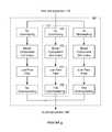
- a system 100 for non-linear digital self-interference cancellationincludes a pre-processor 110 , a non-linear transformer 120 , a transform adaptor 130 , and a post-processor 140 .
- the system 100may additionally or alternatively include a linear transformer 150 and/or an analog signal sampler 160 .
- the system 100functions to reduce self-interference in full-duplex wireless communications systems by canceling non-linear components of self-interference present in digital signals resulting from received RF transmissions.
- Non-linear digital self-interference cancellationmay improve the performance of full-duplex wireless communications systems in numerous operating modes; particularly in operating modes where components of the full-duplex wireless communications systems are operating in substantially non-linear regimes (e.g. operating modes designed to maximize transmission power, power efficiency, etc.).
- the system 100reduces non-linear digital self-interference by passing a digital transmit signal through the pre-processor 110 , which samples digital transmit signals in the transmission path and passes the sampled digital transmit signals to the non-linear transformer 120 .
- the non-linear transformer 120generates a non-linear self-interference cancellation signal based on the input transmit signal and a transform configuration set by the transform adaptor 130 .
- the non-linear cancellation signalis then combined with the digital receive signal originating from an RF receiver by the post-processor 140 to remove self-interference in the digital receive signal.
- the system 100includes a linear transformer 150
- the linear transformer 150preferably operates in parallel with the non-linear transformer 120 to remove both linear and non-linear components of self interference in the digital receive signal.
- the output of the analog signal sampler 160may be used as input to the non-linear transformer 120 and/or to tune the non-linear transformer 120 (preferably through the transform adaptor 130 ).
- the system 100may be implemented using a general purpose processor, a digital signal processor, an application specific integrated circuit (ASIC), a field programmable gate array (FPGA) and/or any suitable processor(s) or circuit(s).
- the system 100preferably includes memory to store configuration data, but may additionally or alternatively be configured using externally stored configuration data or in any suitable manner.
- the system 100is preferably implemented using a full-duplex radio. Additionally or alternatively, the system 100 may be implemented as active sensing systems (e.g., RADAR), wired communications systems, wireless communications systems, and/or any other suitable system, including communications systems where transmit and receive bands are close in frequency, but not overlapping.
- active sensing systemse.g., RADAR
- wired communications systemse.g., wired communications systems
- wireless communications systemse.g., a wireless communications systems
- any other suitable systemincluding communications systems where transmit and receive bands are close in frequency, but not overlapping.
- the pre-processor 110functions to sample digital transmit signals for further processing by the non-linear transformer 120 , as shown in FIG. 3 .
- Digital transmit signals sampled by the pre-processor 110preferably include digital signals originating from an electronic device, destined for an RF transmitter of a full-duplex radio (or other full-duplex wireless communications system).
- Digital transmit signals sampled by the pre-processor 110may additionally or alternatively include digital transmit signals from the analog signal sampler 160 or from any other suitable source.
- Digital transmit signals sampled by the pre-processor noare preferably encoded for conversion to an analog signal by an RF transmitter, (e.g., encoded via PSK, QAM, OFDM, etc.) but may additionally or alternatively be encoded in any suitable way.
- an RF transmittere.g., encoded via PSK, QAM, OFDM, etc.
- the pre-processor 110preferably samples digital transmit signals corresponding to a native sampling rate; that is, the pre-processor no preferably passes all digital transmit data to the non-linear transformer 120 . Additionally or alternatively, the pre-processor 110 may sample a subset of digital transmit signal data; for instance, if a digital transmit signal has a native sample rate of 40 MHz, the pre-processor 110 might discard every other sample before passing to the non-linear transformer 120 , corresponding to a sample rate of 20 MHz (while the RF transmitter may still receiver all samples, corresponding to a sample rate of 40 MHz).
- the pre-processor nomay additionally or alternatively interpolate digital transmit signals to increase or decrease sampling rate. In one instance, the pre-processor 110 modifies the sampling rate of a digital transmit signal to match a sampling rate of an RF receiver of a full-duplex radio.
- the pre-processor nomay perform pre-processing to prepare sampled digital transmit signals for processing by the non-linear transformer 120 .
- the pre-processor nomay include various operators for pre-processing such as scaling, shifting, and/or otherwise modifying the digital transmit signals.
- the pre-processor 110modifies sampled digital transmit signals by removing information unlikely to substantially affect the output of the non-linear transformer 120 . This may include, for instance, dropping samples if the samples do not represent a change above some change threshold from previous samples. As another example, if digital transmit signals correspond to a particular amplitude of an output analog signal, only digital signal data corresponding to an amplitude above some amplitude threshold may be passed to the non-linear transformer 120 .
- the pre-processor nomay additionally or alternatively combine the signals in any suitable way or may select one signal over another.
- the pre-processor 110may pass the average of the two signals to the non-linear transformer 120 .
- the pre-processor 110may prefer the analog signal sampler originating digital transmit signal over the transmit-path digital transmit signal above a certain transmitter power, and vice versa at or below that transmitter power. The selection and combination of the two signals may be dependent on any suitable condition.
- the pre-processor 110may provide different versions of the sampled digital transmit signals to the different inputs.
- the pre-processor nomay pass identical signals to both a non-linear transformer 120 and a linear transformer 150 .
- the pre-processor 110may pass every fourth sample of a digital signal to the non-linear transformer 120 and every sample of a digital signal to the linear transformer 150 (this might be useful if the non-linear distortions of the signal change more slowly than the linear distortions).
- the pre-processor nomay split the sampled digital signal into “linear” and “non-linear” components, where “linear” and “non-linear” components correspond to components of the digital signal more likely to have an effect on linear distortions in received self-interference and non-linear distortions in received self-interference respectively.
- the non-linear transformer 120functions to transform sampled digital transmit signals into non-linear self-interference signals; that is, signals that represent a hypothesized contribution of non-linear self-interference to a received digital signal.
- Non-linear self-interference contributionsmay result from a variety of sources, including components in both RF receivers and RF transmitters of full-duplex radios (e.g., mixers, power amplifiers, ADCs, DACs, etc.). Further, non-linear self-interference contributions may vary randomly, or with environmental or input conditions (e.g. transmission power, ambient temperature, etc.).
- the non-linear transformer 120preferably transforms sampled digital transmit signals through the use of mathematical models adapted to model non-linear self-interference contributions of the RF transmitter, RF receiver, and/or other sources.
- mathematical modelsthat may be used by the non-linear transformer 120 include generalized memory polynomial (GMP) models, Volterra models, and Wiener-Hammerstein models; the non-linear transformer 120 may additionally or alternatively use any combination or set of models.
- the non-linear transformer 120may additionally or alternatively generate mathematical models for modeling non-linear self-interference contributions based on comparisons of sampled digital transmit signals to received signals (from the analog signal sampler 150 , the receive path, or any other suitable source). These models may be generated from previously known models or may be created using neural network and/or machine learning techniques.
- GMP modelsmodel non-linear self-interference contributions as a sum or product of signals having different order; for example, a general form of a GMP is as follows:
- the bandwidth of terms of order kare generally k times larger than the bandwidth of the input signal; for example, if an input signal x[n] has a bandwidth of 40 MHz, the third order terms (e.g., x[n]
- the input signalis preferably sampled at a sampling rate of 120 MHz (three times more than an initial Nyquist sampling rate of 40 MHz). As the number of terms increase, so does the ability to model non-linear self-interference effects, but so also does the minimum sampling rate to avoid aliasing.
- the RF transmittermay also have to match this increased sampling rate in order to subtract non-linear digital interference signals from received signals. For example, if a GMP model uses 7 th order terms, for the same 40 MHz transmit signal the RF receiver may have to sample the received signal at a rate of 280 MHz to avoid aliasing issues (and likewise, the transmit signal may have to be sampled at the same rate).
- the non-linear transformer 120addresses these issues by separating the model used to generate non-linear interference signals into components, each components corresponding to an output order (e.g., one component containing x[n] terms, another component containing x[n]
- the non-linear transformerincludes a number of transform paths 121 , each of which may include an upsampler 122 , a model component 123 , a filter 124 , and a downsampler 125 , as shown in FIG. 4 .
- Each transform path 121corresponds to a model component 123 of a particular order; when a digital transmit signal is passed to a transform path 121 , the transform path 121 first upsamples the digital transmit signal by passing it to the upsampler 122 .
- the upsampler 122functions to increase the number of samples contained within the digital transmit signal in order to reduce aliasing effects. Note that for the first order term of the model, upsampling may not be necessary.
- the upsampler 122preferably increases the number of samples contained within a digital transmit signal according to linear interpolation, but may additionally or alternatively use any suitable method.
- the upsampler 122upsamples the digital transmit signal by creating a sequence comprising the original samples separated by L ⁇ 1 zeroes (where L the upsampling factor) and then passing the new signal through a finite impulse response (FIR) lowpass filter.
- FIRfinite impulse response
- the upsampler 122creates a sequence comprising the original samples separated from each other by L ⁇ 1 new samples, where each new sample is modeled on how a DAC converts digital samples to an analog signal (e.g. if the output of the DAC is not exactly linear between outputs).
- the upsampler 122For a transmit path 121 (and model component 123 ) of order k, the upsampler 122 preferably upsamples the digital transmit signal with an upsampling factor of k, but may additionally or alternatively upsample the digital transmit signal by any suitable factor.
- the model component 123represents the part of the model producing an output of a particular signal order; for instance, a model component 123 of order 3 corresponding to a GMP model might be represented as c n3 x[n]
- the model component 123preferably includes model terms of a single order only, but may additionally or alternatively include model terms of more than one order.
- the model component 123preferably comprises a set of expressions from a generalized memory polynomial (GMP) model, Volterra model, Wiener-Hammerstein model, or neural network model, but may additionally or alternatively comprise a part or whole of any suitable model or combination of models.
- GMPgeneralized memory polynomial
- the model component 123preferably takes the correspondingly upsampled digital transmit signal as input and outputs a non-linear interference signal component.
- the filter 124functions to reduce the bandwidth of non-linear interference signal components to prepare the non-linear interference signal components for combination with digital signals received from the RF receiver (or other suitable source).
- the filter 124is preferably a digitally implemented FIR lowpass filter, but may additionally or alternatively be any suitable type of filter (e.g., infinite impulse response (IIR) fillers, fourier-transform based fillers).
- the filter 124preferably reduces the bandwidth of non-linear interference signal components to match the bandwidth of the digital baseband signal received from the RF transmitter, but may additionally or alternatively function to cap the bandwidth of non-linear interference signal components at any value below the maximum bandwidth of all non-linear interference signal components produced by model components 123 .
- the filter 124preferably functions both to prepare the non-linear interference signal components for downsampling and to remove non-linear interference signal components not found in the received baseband signal (e.g., if the RF receiver has a corresponding lowpass filter for the baseband analog or digital signals or potentially a corresponding bandpass filter for the RF signal).
- the downsampler 125functions to reduce the number of samples contained within a non-linear interference signal component generated by a model component 123 (and preferably filtered by a filter 124 ).
- the downsampler 125preferably downsamples non-linear interference signal components by simply removing signals at a particular interval (e.g., throwing away every other sample to halve the number of samples) but may additionally or alternatively downsample non-linear interference signal components by any suitable method.
- the downsampler 125preferably downsamples non-linear interference signal components to match the sampling rate of the received digital baseband signal, but may additionally or alternatively downsample non-linear interference signal components to any suitable sampling rate.
- the non-linear interference signal componentsare preferably combined by the non-linear transformer 120 before being sent to the post-processor 140 ; additionally or alternatively, the non-linear transformer 120 may pass the non-linear interference signal components to the post-processor 140 without combining them.
- the non-linear transformer 120preferably combines non-linear interference signal components by adding them, but may additionally or alternatively combine them in any suitable way (e.g. scaling components before adding them and/or combining components multiplicatively).
- the transform adaptor 130functions to set the transform configuration of the non-linear transformer 120 .
- the transform adaptor 130may additionally set the transform configuration of the linear transformer 150 if present; the details below discussing the transform configuration of the non-linear transformer 120 are preferably also applicable to the transform configuration of the linear transformer 150 unless otherwise stated.
- the transform configurationpreferably includes the type of model or models used by the non-linear transformer 120 as well as configuration details pertaining to the models (each individual model is a model type paired with a particular set of configuration details). For example, one transform configuration might set the non-linear transformer 120 to use a GMP model with a particular set of coefficients. If the model type is static, the transform configuration may simply include model configuration details; for example, if the model is always a GMP model, the transform configuration may include only coefficients for the model, and not data designating the model type.
- the transform configurationmay additionally or alternatively include other configuration details related to the non-linear transformer 120 .
- the transform adaptor 130may set the number of these transform paths 121 , which model order their respective model components 123 correspond to, the type of filtering used by the filter 124 , and/or any other suitable details.
- the transform configurationmay include any details relating to the computation or structure of the non-linear transformer 120 .
- Transform configurationsare preferably selected and/or generated by the transform adaptor 130 .
- the transform adaptor 130may set an appropriate transform configuration by selecting from stored static configurations, from generating configurations dynamically, or by any other suitable manner or combination of manners.
- the transform adaptor 130may choose from three static transform configurations based on their applicability to particular signal and/or environmental conditions (the first is appropriate for low transmitter power, the second for medium transmitter power, and the third for high transmitter power).
- the transform adaptor 130may dynamically generate configurations based on signal and/or environmental conditions; the coefficients of a GMP model are set by a formula that takes transmitter power, temperature, and receiver power as input.
- the transform adaptor 130preferably sets transform configurations based on a variety of input data (whether transform configurations are selected from a set of static configurations or generated according to a formula or model).
- Input data used by the transform adaptor 130may include static environmental and system data (e.g. receiver operating characteristics, transmitter operating characteristics, receiver elevation above sea-level), dynamic environmental and system data (e.g. current ambient temperature, current receiver temperature, average transmitter power, ambient humidity), and/or system configuration data (e.g. receiver/transmitter settings), signal data (e.g., digital transmit signal, RF transmit signal, RF receive signal, digital receive signal). If the system 100 uses an analog signal sampler 160 , the transform adaptor 130 may additionally or alternatively use output of the analog signal sampler 160 as input for setting transform configurations.
- static environmental and system datae.g. receiver operating characteristics, transmitter operating characteristics, receiver elevation above sea-level
- dynamic environmental and system datae.g. current ambient temperature, current receiver temperature, average transmitter power, ambient humidity
- system configuration datae.g
- the transform adaptor 130may additionally or alternatively generate and/or use models based on this input data to set transform configurations; for example, a transmitter manufacturer may give a model to predict internal temperature of the transmitter based on transmitter power, and the transform adaptor 130 may use the output of this model (given transmitter power) as input data for setting transform configurations.
- the transform adaptor 130may set transform configurations at any time, but preferably sets transform configurations in response to either a time threshold or other input data threshold being crossed. For example, the transform adaptor 130 may re-set transform configurations every ten seconds according to changed input data values. As another example, the transform adaptor 130 may re-set transform configurations whenever transmitter power thresholds are crossed (e.g. whenever transmitter power increases by ten percent since the last transform configuration setting, or whenever transmitter power increases over some static value).
- the transform adaptor 130may cooperate with the analog canceller (for instance, setting transform configurations based on data from the analog canceller, or coordinating transform configuration setting times with the analog canceller) to reduce overall self-interference (or for any other suitable reason).
- the transform adapter 130preferably adapts transform configurations and/or transform-configuration-generating algorithms (i.e., algorithms that dynamically generate transform configurations) to reduce self-interference for a given transmit signal and set of system/environmental conditions.
- the transform adapter 130may adapt transform configurations and/or transform-configuration-generating algorithms using analytical methods, online gradient-descent methods (e.g., LMS, RLMS), and/or any other suitable methods.
- Adapting transform configurationspreferably includes changing transform configurations based on learning. In the case of a neural-network model, this might include altering the structure and/or weights of a neural network based on test inputs. In the case of a GMP polynomial model, this might include optimizing GMP polynomial coefficients according to a gradient-descent method.
- the transform adaptor 130may adapt transform configurations based on test input scenarios (e.g. scenarios when the signal received by the RF receiver is known), scenarios where there is no input (e.g. the only signal received at the RF receiver is the signal transmitted by the RF transmitter), or scenarios where the received signal is unknown. In cases where the received signal is an unknown signal, the transform adaptor 130 may adapt transform configurations based on historical received data (e.g. what the signal looked like ten seconds ago) or any other suitable information.
- test input scenariose.g. scenarios when the signal received by the RF receiver is known
- scenarios where there is no inpute.g. the only signal received at the RF receiver is the signal transmitted by the RF transmitter
- scenarios where the received signalis unknown.
- the transform adaptor 130may adapt transform configurations based on historical received data (e.g. what the signal looked like ten seconds ago) or any other suitable information.
- the transform adaptor 130may additionally or alternatively adapt transform configurations based on the content of the transmitted signal; for instance, if the transmitted signal is modulated in a particular way, the transform adaptor 130 may look for that same modulation in the self-interference signal; more specifically, the transform adaptor 130 may adapt transform configurations such that when the self-interference signal is combined with the digital receive signal the remaining modulation (as an indicator of self-interference) is reduced (compared to a previous transform configuration).
- the post-processor 140functions to combine non-linear self interference signals generated by the non-linear transformer 120 with digital signals received by the RF receiver, as shown in FIG. 5 .
- the post-processor 140preferably combines non-linear self-interference signals from the non-linear transformer 120 with digital receive signals from an RF receiver of a full-duplex wireless communications system. Additionally or alternatively, the post-processor 140 may combine linear self-interference signals from the linear transformer 150 with digital receive signals from an RF receiver of a full-duplex wireless communications system.
- the post-processor 140may additionally or alternatively combine linear or non-linear self-interference signals with any suitable digital receive signal.
- Digital receive signals entering the post-processor 140are preferably encoded for conversion to an analog signal by an RF transmitter, (e.g., encoded via PSK, QAM, OFDM, etc.) but may additionally or alternatively be encoded in any suitable way.
- the post-processor 140may perform post-processing to prepare self-interference signals for combination with digital receive signals; this may include scaling, shifting, filtering, and/or otherwise modifying the self-interference signals.
- the post-processor 140may include a lowpass filter designed to filter out high-frequency components of generated self-interference signals (e.g., to match a corresponding bandwidth of the RF transmitter). If the system 100 includes a linear transformer 150 , the post-processor may combine the output of the linear transformer 150 and the non-linear transformer 120 before combining the (potentially weighted) combination of the two signals with digital receive signals.
- the post-processor 140preferably matches the sampling rate of self-interference signals output by the non-linear transformer 120 and the linear transformer 150 with the sampling rate of the output of the RF receiver through upsampling and/or downsampling as previously described, but may additionally or alternatively not alter the sampling rate of self-interference signals or set the sampling rate of self-interference signals to a sampling rate other than that of RF receiver output.
- the post-processor 140may combine output from the non-linear transformer 120 and the linear transformer 150 (if present) in any suitable way, including combining non-linear or linear self-interference signal components.
- the post-processor 140may combine output from the non-linear transformer 120 and the linear transformer 150 as a weighted sum.
- the post-processor 140may select output from one of the two transformers (or may select subsets of output from either or both; e.g., two of five non-linear self-interference signal components). If the pre-processor no splits digital transmit signals between the linear transformer 150 and the non-linear transformer 120 , the post-processor 140 may rejoin said digital signals based on the split (e.g. by performing a joining operation that is an approximate inverse of the splitting operation).
- the linear transformer 150functions to transform sampled digital transmit signals into linear self-interference signals; that is, signals that represent a hypothesized contribution of linear self-interference to a received digital signal.
- linear self-interference contributionsmay result from a variety of sources. Non-linearity often stems from non-linear behavior of typical wireless transmitter components, while the actual wireless channel may often be very linear in response.
- split modelsallows for the simpler linear self-interference model to be tuned and adjusted at a fast rate without having to also tune and adjust the more computationally complex non-linear self-interference model. This concept may be extended to having separate non-linear models for the transmitter and receiver, as shown in FIG. 6 .
- the linear transformer 150preferably transforms sampled digital transmit signals through the use of mathematical models adapted to model linear self-interference contributions of the RF transmitter, RF receiver, the wireless channel, and/or other sources.
- mathematical modelsthat may be used by the linear transformer 150 include generalized memory polynomial (GMP) models, Volterra models, and Wiener-Hammerstein models; the non-linear transformer 120 may additionally or alternatively use any combination or set of models.
- the linear transformer 150may additionally or alternatively generate mathematical models for modeling linear self-interference contributions based on comparisons of sampled digital transmit signals to received signals (from the analog signal sampler 150 , the receive path, or any other suitable source). These models may be generated from previously known models or may be created using neural network and/or machine learning techniques.
- the analog signal sampler 160functions to provide a digital signal converted from the RF transmit signal (and/or a baseband or intermediate frequency analog signal) to the system 100 .
- This digital signaldiffers from the digital transmit signal in that it may contain non-linearities resulting from the conversion of the digital transmit signal to an RF transmit signal (and/or baseband or intermediate frequency analog transmit signal) and back again, but also differs from the RF receive signal in that it results from a different signal path (e.g., the analog signal is sampled before reaching the antenna).
- the analog signal sampler 160may be used to provide information to the non-linear transformer 120 , linear transformer 150 , and/or transform adaptor 130 that the digital transmit signal may not contain.
- the analog signal sampler 160 outputis preferably directed to appropriate sources by the pre-processor no, but the analog signal sampler 160 may additionally or alternatively output to any suitable part of the system 100 (including the non-linear transformer 120 and/or the transform adaptor 130 ).
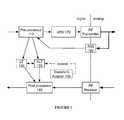
- the system 100includes a digital pre-distortion circuit (DPD) 170 , as shown in FIG. 7 .
- DPDdigital pre-distortion circuit
- FIG. 7An example of non-linear distortion occurring when converting a digital transmit signal to an RF transmit signal is as shown in FIG. 8A .
- One way to do thisinvolves pre-distorting the digital transmit signal such that the distortions in the digital transmit signal serve to correct distortions introduced by the RF transmitter in converting the digital transmit signal to an RF transmit signal, as shown in FIG. 8B .
- the DPD 170preferably takes samples (which may be digital or analog) from the output of the RF transmitter to measure the non-linearity inherent in the RF transmitter output.
- the DPD 170preferably receives samples from the analog signal sampler 160 but may additionally or alternatively receive them from any suitable source. Based on the RF transmitter output samples, the DPD 170 transforms the digital transmit signal to create ‘inverse’ non-linearity in the signal (as shown in FIG. 8B ). This ‘inverse’ non-linearity, when further transformed by the RF transmitter (in the process of converting the digital transmit signal to an RF transmit signal) reduces the non-linearity present in the final RF transmit signal.
- Pre-distortion(or other linearization techniques) provided by the DPD 170 or other suitable sources may be leveraged to reduce the complexity of digital self-interference cancellation.
- the DPD 170By placing the DPD 170 after the pre-processor no in the digital transmit signal path (as shown in FIG. 7 ), non-linearity in the receive signal path is reduced, and additionally, the non-linear transformer 120 does not need to transform the digital transmit signal to remove non-linearities introduced by the DPD 170 (as it may need to if the DPD 170 occurred before the pre-processor no in the digital transmit signal path).
- a method 200 for non-linear digital self-interference cancellationincludes receiving a digital transmit signal S 210 , transforming the digital transmit signal into a non-linear self-interference signal according to a transform configuration S 220 , and combining the non-linear self-interference signal with a digital receive signal S 230 .
- the method 200may additionally include pre-processing the digital transmit signal S 215 , transforming the digital transmit signal into a linear self-interference signal S 225 , dynamically adapting the transform configuration S 240 , and/or digitally pre-distorting the digital transmit signal S 250 .
- the method 200functions to reduce self-interference in full-duplex wireless communications systems by canceling non-linear components of self-interference present in digital signals resulting from received RF transmissions.
- Non-linear digital self-interference cancellationmay improve the performance of full-duplex wireless communications systems in numerous operating modes; particularly in operating modes where components of the full-duplex wireless communications systems are operating in substantially non-linear regimes (e.g. operating modes designed to maximize transmission power, power efficiency, etc.).
- the method 200reduces non-linear digital self-interference in full-duplex wireless communications systems by sampling a digital transmit signal (Step S 210 ).
- the received digital transmit signalmay be pre-processed (potentially into linear and non-linear components) during Step S 215 , after which point the digital transmit signal may be transformed into a non-linear self-interference signal according to a transform configuration (Step S 220 ) and optionally also into a linear self-interference signal (Step S 225 ).
- the self-interference signalsare then combined with a digital receive signal of the full-duplex wireless communication system (Step S 230 ) in order to reduce self-interference signals present in the signal received by the wireless communication system.
- the method 200may also include adapting the transform configuration dynamically (Step S 240 ) in order to increase the effectiveness of self-interference reduction due to non-linear self-interference transformation and/or digitally pre-distorting the digital transmit signal before the transmitter of the wireless communication signal (Step S 250 ) in order to reduce the amount of non-linear self-interference present in received digital transmit signals (which may reduce computational power required for computations in Steps S 220 , S 225 , and/or S 240 ).
- the method 200is preferably implemented by the system 100 , but may additionally or alternatively be implemented by any suitable system for non-linear digital self-interference cancellation used with full-duplex wireless communications systems. Additionally or alternatively, the method 200 may be implemented using active sensing systems (e.g., RADAR), wired communications systems, wireless communications systems, and/or any other suitable system, including communications systems where transmit and receive bands are close in frequency, but not overlapping.
- active sensing systemse.g., RADAR
- wired communications systemse.g., wireless communications systems
- wireless communications systemse.g., a wireless communications systems
- any other suitable systemincluding communications systems where transmit and receive bands are close in frequency, but not overlapping.
- Step S 210includes receiving a digital transmit signal.
- Step S 210functions to provide a digital signal intended for transmission by a full-duplex wireless communications system so that the signal may be used to remove self-interference at the full-duplex wireless communications system receiver.
- Digital transmit signals received in S 210preferably include digital signals originating from an electronic device, destined for an RF transmitter of a full-duplex radio (or other full-duplex wireless communications system).
- Digital transmit signals received in S 210may additionally or alternatively include digital transmit signals converted from analog transmit signals (e.g., the RF transmission signal of the RF transmitter of a full-duplex radio) or from any other suitable source.
- Digital transmit signals received in S 210are preferably encoded for conversion to an analog signal by an RF transmitter, (e.g., encoded via PSK, QAM, OFDM, etc.) but may additionally or alternatively be encoded in any suitable way.
- Step S 215includes pre-processing the digital transmit signal.
- Step S 215functions to perform initial processing on the digital transmit signal received in S 210 (if desired).
- Step S 215preferably includes pre-processing all data received in S 210 ; additionally or alternatively, S 215 may include sampling a subset of digital transmit signal data; for instance, if a digital transmit signal has a native sample rate of 40 MHz, S 215 might include discarding every other sample as part of pre-processing, corresponding to a sample rate of 20 MHz.
- Step S 215may additionally or alternatively include upsampling or downsampling digital transmit signals to increase or decrease sampling rate.
- S 215includes modifying the sampling rate of a digital transmit signal to match a sampling rate of an RF receiver of a full-duplex radio.
- S 215includes modifying digital transmit signals by removing information unlikely to substantially affect the result of non-linear transformation. This may include, for instance, removing signal components if they do not represent a change above some change threshold over previous signal components. As another example, if digital transmit signals correspond to a particular amplitude of an output analog signal, digital signal data corresponding to an amplitude below some amplitude threshold may be removed.
- S 215may include combining the signals in any suitable way or may select one signal over another. For instance, two signals may be combined by taking the average of the two signals or summing them. As another example, S 215 may include selecting an analog signal sampler originating digital transmit signal over the transmit-path digital transmit signal above a certain transmitter power, and vice versa at or below that transmitter power.
- Step S 215may additionally or alternatively perform any pre-processing to prepare digital transmit signals for non-linear and/or linear transformation. This may include scaling, shifting, and/or otherwise modifying the digital transmit signals. If digital transmit signals undergo more than one type of transformation as part of the method 200 (e.g. both linear and non-linear transformation), S 215 may include providing different versions of the digital transmit signals for different transformation types. As a first example, S 215 may include providing identical signals for linear and non-linear transformation. As a second example, S 215 may include providing every fourth sample of a digital signal for non-linear transformation and every sample of a digital signal for linear transformation (this might be useful if the non-linear distortions of the signal change more slowly than the linear distortions).
- S 215may include splitting the sampled digital signal into “linear” and “non-linear” components, where “linear” and “non-linear” components correspond to components of the digital signal more likely to have an effect on linear distortions in received self-interference and non-linear distortions in received self-interference respectively.
- Step S 220includes transforming the digital transmit signal into a non-linear self-interference signal according to a transform configuration.
- Step S 220functions to transform digital transmit signals into non-linear self-interference signals; that is, signals that represent a hypothesized contribution of non-linear self-interference to a received digital signal.
- Non-linear self-interference contributionsmay result from a variety of sources, including components in both RF receivers and RF transmitters of full-duplex radios (e.g., mixers, power amplifiers, ADCs, DACs, etc.). Further, non-linear self-interference contributions may vary randomly, or with environmental or input conditions (e.g. transmission power, ambient temperature, etc.).
- Step S 220preferably includes transforming digital transmit signals through the use of mathematical models substantially similar to those described in the description of the system 100 , but may additionally or alternatively transform digital transmit signals according to any model or set of models.
- Step S 220may additionally or alternatively include generating models for modeling non-linear self-interference contributions based on comparisons of sampled digital transmit signals to received signals (from the analog signal samples, the receive path, or any other suitable source).
- S 220transforms digital transmit signals through the use of an order-separated model similar to the one of the system 100 description as shown in FIG. 10 .
- S 220may include transforming digital transmit signals according to transform paths, where each transform path corresponds to a component of the order-separated model.
- Step S 220preferably includes transforming digital transmit signals for each transform path in parallel simultaneously, but may additionally or alternatively transform them serially and/or transform them at separate times. While S 220 preferably includes transforming identical digital transmit signals for each transform path, the digital transmit signals may additionally or alternatively be processed in any suitable way (for instance, S 220 may include splitting the digital transmit signal into components and passing separate components to each transform path).
- S 220preferably includes upsampling the digital transmit signal S 221 , transforming the digital transmit signal with a model component S 222 , filtering the transformed signal S 223 , and downsampling the transformed signal S 224 . Additionally or alternatively, S 220 may include only transforming the digital transmit signal with a model component S 222 and/or filtering the transformed signal S 223 (as with a first-order model component). Step S 220 preferably also includes combining the transformed signals to form a single non-linear self-interference signal, but may additionally or alternatively not combine the transformed signals. Step S 220 preferably combines non-linear interference signal components by adding them, but may additionally or alternatively combine them in any suitable way (e.g. scaling components before adding them and/or combining components multiplicatively).
- Upsampling the digital transmit signal S 221functions to increase the number of samples contained within the digital transmit signal in order to reduce aliasing effects. Note that for the first order term of the model, upsampling may not be necessary.
- Step S 221preferably increases the number of samples contained within a digital transmit signal according to linear interpolation, but may additionally or alternatively use any suitable method.
- S 221includes upsampling the digital transmit signal by creating a sequence comprising the original samples separated by L ⁇ 1 zeroes (where L the upsampling factor) and then passing the new signal through a finite impulse response (FIR) lowpass filter.
- FIRfinite impulse response
- S 221includes creating a sequence comprising the original samples separated from each other by L ⁇ 1 new samples, where each new sample is modeled on how a DAC converts digital samples to an analog signal (e.g. if the output of the DAC is not exactly linear between outputs).
- S 221preferably includes upsampling the digital transmit signal with an upsampling factor of k, but may additionally or alternatively upsample the digital transmit signal by any suitable factor.
- Transforming the digital transmit signal with a model component S 222functions to transform the digital transmit signal into a non-linear interference signal component based on the part of the model producing an output of a particular signal order; for instance, a model component of order 3 corresponding to a GMP model might be represented as c n3 x[n]
- Model componentspreferably include model terms of a single order only, but may additionally or alternatively include model terms of more than one order.
- Model componentspreferably comprise a set of expressions from a generalized memory polynomial (GMP) model, Volterra model, Wiener-Hammerstein model, or neural network model, but may additionally or alternatively comprise a part or whole of any suitable model or combination of models.
- GMPgeneralized memory polynomial
- Filtering the transformed signal S 223functions to reduce the bandwidth of non-linear interference signal components to prepare the non-linear interference signal components for combination with digital signals received from the RF receiver (or other suitable source). Filtering is preferably implemented using a digitally implemented FIR lowpass filter, but may additionally or alternatively use any suitable type of filter (e.g., infinite impulse response (IIR) filters, fourier-transform based filters).
- Step S 223preferably includes reducing the bandwidth of non-linear interference signal components to match the bandwidth of the digital baseband signal received from the RF transmitter, but may additionally or alternatively function to cap the bandwidth of non-linear interference signal components at any value below the maximum bandwidth of all non-linear interference signal components produced by model components.
- Step S 223preferably functions both to prepare the non-linear interference signal components for downsampling and to remove non-linear interference signal components not found in the received baseband signal (e.g., if the RF receiver has a corresponding lowpass filter for the baseband analog or digital signals or potentially a corresponding bandpass filter for the RF signal).
- Step S 224Downsampling the transformed signal S 224 functions to reduce the number of samples contained within a non-linear interference signal component.
- Step S 224preferably includes downsampling non-linear interference signal components by simply removing signals at a particular interval (e.g., throwing away every other sample to halve the number of samples) but may additionally or alternatively downsample non-linear interference signal components by any suitable method.
- Step S 224preferably downsamples non-linear interference signal components to match the sampling rate of the received digital baseband signal, but may additionally or alternatively downsample non-linear interference signal components to any suitable sampling rate.
- Step S 225includes transforming the digital transmit signal into a linear self-interference signal.
- Step S 225functions to transform sampled digital transmit signals into linear self-interference signals; that is, signals that represent a hypothesized contribution of linear self-interference to a received digital signal.
- linear self-interference contributionsmay result from a variety of sources. Non-linearity often stems from non-linear behavior of typical wireless transmitter components, while the actual wireless channel may often be very linear in response.
- split modelsallows for the simpler linear self-interference model to be tuned and adjusted at a fast rate without having to also tune and adjust the more computationally complex non-linear self-interference model. This concept may be extended to having separate non-linear models for the transmitter and receiver, as shown in FIG. 6 .
- Step S 225preferably includes transforming sampled digital transmit signals through the use of mathematical models adapted to model linear self-interference contributions of the RF transmitter, RF receiver, the wireless channel, and/or other sources.
- mathematical modelsthat may be used include generalized memory polynomial (GMP) models, Volterra models, and Wiener-Hammerstein models; S 225 may additionally or alternatively include the use of any combination or set of models.
- Step S 230includes combining the non-linear self-interference signal with a digital receive signal.
- Step S 230functions to combine non-linear self interference signals with digital signals received by the RF receiver.
- Step S 230preferably includes combining non-linear self-interference signals with digital receive signals from an RF receiver of a full-duplex wireless communications system; additionally or alternatively, S 230 may include combining linear self-interference signals with digital receive signals from an RF receiver of a full-duplex wireless communications system.
- Step S 230may additionally or alternatively include combining linear or non-linear self-interference signals with any suitable digital receive signal.
- Step S 230may include performing post-processing to prepare self-interference signals for combination with digital receive signals; this may include scaling, shifting, filtering, and/or otherwise modifying the self-interference signals.
- S 230may include processing self-interference signals with a lowpass filter designed to filter out high-frequency components (e.g., to match a corresponding bandwidth of the RF transmitter).
- Step S 230may include matching the sampling rate of self-interference signals with the sampling rate of the output of the RF receiver through upsampling and/or downsampling as previously described, but may additionally or alternatively not alter the sampling rate of self-interference signals or set the sampling rate of self-interference signals to a sampling rate other than that of RF receiver output.
- Step S 230may include combining linear and non-linear self-interference signals in any suitable way, including combining non-linear or linear self-interference signal components.
- S 230may include combining linear and non-linear self-interference signals as a weighted sum.
- Step S 240includes dynamically adapting the transform configuration.
- Step S 240functions to update and/or change the transform configuration used in non-linear transformation (and potentially also the parameters of linear transformation) based on changes in signal or environmental conditions.
- the transform configurationis preferably as described in the system 100 description, but may additionally or alternatively comprise any parameter or set of parameters corresponding to non-linear or linear signal transformation performed in S 220 and S 225 .
- Dynamically adapting the transform configuration S 240may include setting an updated transform configuration by selecting from stored static configurations, from generating a new transform configuration, or by any other suitable manner or combination of manners.
- S 240may include choosing from three static transform configurations based on their applicability to particular signal and/or environmental conditions (the first is appropriate for low transmitter power, the second for medium transmitter power, and the third for high transmitter power).
- S 240may include generating an updated configuration based on signal and/or environmental conditions; if a GMP model is used in non-linear transformation, the coefficients of a GMP model may be computed by a formula that takes transmitter power, temperature, and receiver power as input.
- Step S 240may include setting transform configurations based on a variety of input data (whether transform configurations are selected from a set of static configurations or generated according to a formula or model).
- Input datamay include static environmental and system data (e.g. receiver operating characteristics, transmitter operating characteristics, receiver elevation above sea-level), dynamic environmental and system data (e.g. current ambient temperature, current receiver temperature, average transmitter power, ambient humidity), and/or system configuration data (e.g. receiver/transmitter settings), signal data (e.g., digital transmit signal, RF transmit signal, RF receive signal, digital receive signal).
- static environmental and system datae.g. receiver operating characteristics, transmitter operating characteristics, receiver elevation above sea-level
- dynamic environmental and system datae.g. current ambient temperature, current receiver temperature, average transmitter power, ambient humidity
- system configuration datae.g. receiver/transmitter settings
- signal datae.g., digital transmit signal, RF transmit signal, RF receive signal, digital receive signal.
- Step S 240may be performed at any time, but is preferably performed in response to either a time threshold or other input data threshold being crossed.
- S 240may adapt transform configurations every ten seconds according to changed input data values.
- transform configurationsmay be re-set whenever transmitter power thresholds are crossed (e.g. whenever transmitter power increases by ten percent since the last transform configuration setting, or whenever transmitter power increases over some static value).
- Step S 240may additionally or alternatively include cooperating with analog cancellation methods of a full-duplex radio if present; for instance, adapting transform configurations based on analog cancellation data, or coordinating transform configuration setting times based on analog cancellation configurations to reduce overall self-interference (or for any other suitable reason).
- Step S 240preferably adapts transform configurations to reduce self-interference for a given transmit signal and set of system/environmental conditions.
- Step S 240may adapt transform configurations and/or transform-configuration-generating algorithms using analytical methods, online gradient-descent methods, least-mean-squares (LMS) methods, recursive-least-squares (RLS) methods, regularized and constrained solver methods (e.g. LASSO), and/or any other suitable methods.
- LMS methodsmay include regularization, one example LMS method includes leaky LMS; RLS methods may also include regularization.
- Adapting transform configurationspreferably includes changing transform configurations based on learning.
- thismight include altering the structure and/or weights of a neural network based on test inputs.
- thismight include optimizing GMP polynomial coefficients according to a gradient-descent method.
- Step S 240may additionally or alternatively include adapting transform configurations based on test input scenarios (e.g. scenarios when the signal received by the RF receiver is known), scenarios where there is no input (e.g. the only signal received at the RF receiver is the signal transmitted by the RF transmitter), or scenarios where the received signal is unknown.
- transform configurationsmay be adapted based on historical received data (e.g. what the signal looked like ten seconds ago) or any other suitable information.
- Transform configurationsmay additionally or alternatively be updated based on the content of the transmitted signal.
- Step S 250includes digitally pre-distorting the digital transmit signal using a digital pre-distortion circuit.
- Step S 250functions to increase transmitter efficiency and/or reduce the amount of non-linear self-interference cancellation required by a full-duplex radio. Because a large portion of non-linearities in full-duplex wireless communications systems arise from components of the RF transmitter, and these non-linearities may contribute to reduced power efficiency of the RF transmitter, it may be advantageous (both from the perspective of increasing transmitter efficiency and for reducing the amount of non-linear self-interference cancellation needed) to reduce the non-linear components of the RF transmit signal.
- An example of non-linear distortion occurring when converting a digital transmit signal to an RF transmit signalis as shown in FIG. 8A .
- One way to do thisinvolves pre-distorting the digital transmit signal such that the distortions in the digital transmit signal serve to correct distortions introduced by the RF transmitter in converting the digital transmit signal to an RF transmit signal, as shown in FIG. 8B .
- Step S 250preferably includes taking samples (which may be digital or analog) from the output of the RF transmitter to measure the non-linearity inherent in the RF transmitter output. Based on the RF transmitter output samples the digital transmit signal is transformed to create ‘inverse’ non-linearity in the signal (as shown in FIG. 8B ). This ‘inverse’ non-linearity, when further transformed by the RF transmitter (in the process of converting the digital transmit signal to an RF transmit signal) reduces the non-linearity present in the final RF transmit signal.
- Pre-distortionmay be leveraged to reduce the complexity of digital self-interference cancellation.
- pre-distortionafter pre-processing in the signal path, as shown in FIG. 7 , non-linearity in the receive signal path is reduced, and additionally, non-linear transformation does not need to transform the digital transmit signal to remove non-linearities introduced by digital pre-distortion.
- Step S 250may additionally or alternatively include adapting the digital pre-distortion circuit to account for changing RF transmit signal distortion characteristics.
- Adapting the digital pre-distortion circuitis preferably done using substantially similar techniques to those used to update the transform configuration, but may additionally or alternatively be performed using any suitable technique or system.
- the pre-distortion characteristics of the digital pre-distortion circuitare preferably adapted according to samples of the RF transmit signal of the full-duplex wireless communication system, but may additionally or alternatively be adapted according to any suitable input.
- the methods of the preferred embodiment and variations thereofcan be embodied and/or implemented at least in part as a machine configured to receive a computer-readable medium storing computer-readable instructions.
- the instructionsare preferably executed by computer-executable components preferably integrated with a system for non-linear self-interference cancellation.
- the computer-readable mediumcan be stored on any suitable computer-readable media such as RAMs, ROMs, flash memory, EEPROMs, optical devices (CD or DVD), hard drives, floppy drives, or any suitable device.
- the computer-executable componentis preferably a general or application specific processor, but any suitable dedicated hardware or hardware/firmware combination device can alternatively or additionally execute the instructions.
Landscapes
- Engineering & Computer Science (AREA)
- Signal Processing (AREA)
- Physics & Mathematics (AREA)
- Computer Networks & Wireless Communication (AREA)
- General Physics & Mathematics (AREA)
- Mathematical Optimization (AREA)
- Theoretical Computer Science (AREA)
- Computational Mathematics (AREA)
- Pure & Applied Mathematics (AREA)
- Mathematical Analysis (AREA)
- Mathematical Physics (AREA)
- Data Mining & Analysis (AREA)
- General Engineering & Computer Science (AREA)
- Computing Systems (AREA)
- Software Systems (AREA)
- Databases & Information Systems (AREA)
- Algebra (AREA)
- Operations Research (AREA)
- Nonlinear Science (AREA)
- Transceivers (AREA)
- Power Engineering (AREA)
- Transmitters (AREA)
- Noise Elimination (AREA)
Abstract
Description
where the input signal is represented by x[n] and cnkrepresents coefficients of the GMP. The first sum of the GMP captures non-linear self-interference effects occurring based on current values of the input signal, while the second two terms capture non-linear self-interference effects determined by past values of the input signal (known as memory effects).
cn3x[n]|x[n]|2+cn3x[n]|x[n−m]|2
cn3x[n]|x[n]|2+cn3x[n]|x[n−m]|2
Claims (14)
Priority Applications (3)
| Application Number | Priority Date | Filing Date | Title |
|---|---|---|---|
| US14/456,320US8976641B2 (en) | 2013-08-09 | 2014-08-11 | Systems and methods for non-linear digital self-interference cancellation |
| US14/607,571US9667299B2 (en) | 2013-08-09 | 2015-01-28 | Systems and methods for non-linear digital self-interference cancellation |
| US15/496,225US10050659B2 (en) | 2013-08-09 | 2017-04-25 | Systems and methods for non-linear digital self-interference cancellation |
Applications Claiming Priority (2)
| Application Number | Priority Date | Filing Date | Title |
|---|---|---|---|
| US201361864453P | 2013-08-09 | 2013-08-09 | |
| US14/456,320US8976641B2 (en) | 2013-08-09 | 2014-08-11 | Systems and methods for non-linear digital self-interference cancellation |
Related Child Applications (1)
| Application Number | Title | Priority Date | Filing Date |
|---|---|---|---|
| US14/607,571ContinuationUS9667299B2 (en) | 2013-08-09 | 2015-01-28 | Systems and methods for non-linear digital self-interference cancellation |
Publications (2)
| Publication Number | Publication Date |
|---|---|
| US20150043323A1 US20150043323A1 (en) | 2015-02-12 |
| US8976641B2true US8976641B2 (en) | 2015-03-10 |
Family
ID=52448567
Family Applications (3)
| Application Number | Title | Priority Date | Filing Date |
|---|---|---|---|
| US14/456,320ActiveUS8976641B2 (en) | 2013-08-09 | 2014-08-11 | Systems and methods for non-linear digital self-interference cancellation |
| US14/607,571Active2035-01-04US9667299B2 (en) | 2013-08-09 | 2015-01-28 | Systems and methods for non-linear digital self-interference cancellation |
| US15/496,225ActiveUS10050659B2 (en) | 2013-08-09 | 2017-04-25 | Systems and methods for non-linear digital self-interference cancellation |
Family Applications After (2)
| Application Number | Title | Priority Date | Filing Date |
|---|---|---|---|
| US14/607,571Active2035-01-04US9667299B2 (en) | 2013-08-09 | 2015-01-28 | Systems and methods for non-linear digital self-interference cancellation |
| US15/496,225ActiveUS10050659B2 (en) | 2013-08-09 | 2017-04-25 | Systems and methods for non-linear digital self-interference cancellation |
Country Status (5)
| Country | Link |
|---|---|
| US (3) | US8976641B2 (en) |
| EP (1) | EP3031141B8 (en) |
| KR (1) | KR102222353B1 (en) |
| CN (1) | CN105556860B (en) |
| WO (1) | WO2015021461A1 (en) |
Cited By (13)
| Publication number | Priority date | Publication date | Assignee | Title |
|---|---|---|---|---|
| US9413516B2 (en) | 2013-11-30 | 2016-08-09 | Amir Keyvan Khandani | Wireless full-duplex system and method with self-interference sampling |
| US9479322B2 (en) | 2013-11-30 | 2016-10-25 | Amir Keyvan Khandani | Wireless full-duplex system and method using sideband test signals |
| WO2017010623A1 (en)* | 2015-07-14 | 2017-01-19 | 엘지전자 주식회사 | Method for estimating nonlinear self-interference channel in wireless communication system and device for same |
| US9572038B2 (en) | 2012-05-13 | 2017-02-14 | Amir Keyvan Khandani | Full duplex wireless transmission with channel phase-based encryption |
| US9577690B2 (en) | 2007-05-23 | 2017-02-21 | Hypres, Inc. | Wideband digital spectrometer |
| US9820311B2 (en) | 2014-01-30 | 2017-11-14 | Amir Keyvan Khandani | Adapter and associated method for full-duplex wireless communication |
| US9997830B2 (en) | 2012-05-13 | 2018-06-12 | Amir Keyvan Khandani | Antenna system and method for full duplex wireless transmission with channel phase-based encryption |
| US10177896B2 (en) | 2013-05-13 | 2019-01-08 | Amir Keyvan Khandani | Methods for training of full-duplex wireless systems |
| US10333593B2 (en) | 2016-05-02 | 2019-06-25 | Amir Keyvan Khandani | Systems and methods of antenna design for full-duplex line of sight transmission |
| US10700766B2 (en) | 2017-04-19 | 2020-06-30 | Amir Keyvan Khandani | Noise cancelling amplify-and-forward (in-band) relay with self-interference cancellation |
| US10879995B2 (en) | 2018-04-10 | 2020-12-29 | Wilson Electronics, Llc | Feedback cancellation on multiband booster |
| US11012144B2 (en) | 2018-01-16 | 2021-05-18 | Amir Keyvan Khandani | System and methods for in-band relaying |
| US11057204B2 (en) | 2017-10-04 | 2021-07-06 | Amir Keyvan Khandani | Methods for encrypted data communications |
Families Citing this family (67)
| Publication number | Priority date | Publication date | Assignee | Title |
|---|---|---|---|---|
| WO2015021461A1 (en)* | 2013-08-09 | 2015-02-12 | Kumu Networks, Inc. | Systems and methods for non-linear digital self-interference cancellation |
| DE112016000449B4 (en) | 2015-01-23 | 2024-08-08 | Lg Electronics Inc. | Method for estimating a nonlinear self-interference signal channel by a device using an FDR scheme |
| US10333570B2 (en) | 2015-01-23 | 2019-06-25 | Lg Electronics Inc. | Method and device for removing self-interference signal in environment using FDR mode |
| US9894539B2 (en)* | 2015-04-06 | 2018-02-13 | Maxlinear Asia Singapore PTE LTD | Digital full duplex over single channel solution for small cell backhaul applications |
| US10447505B2 (en) | 2015-05-29 | 2019-10-15 | Lg Electronics Inc. | Method for performing self-interference cancellation in FDR environment and device for same |
| WO2016195204A1 (en)* | 2015-06-01 | 2016-12-08 | 엘지전자 주식회사 | Method for performing self-interference cancellation by communication device using fdr mode |
| US9912464B2 (en) | 2015-07-15 | 2018-03-06 | Cisco Technology, Inc. | Interference relationship characterization in full duplex cable network environments |
| US10033542B2 (en) | 2015-07-15 | 2018-07-24 | Cisco Technology, Inc. | Scheduling mechanisms in full duplex cable network environments |
| US9942024B2 (en) | 2015-07-15 | 2018-04-10 | Cisco Technology, Inc. | Full duplex network architecture in cable network environments |
| US9966993B2 (en) | 2015-07-15 | 2018-05-08 | Cisco Technology, Inc. | Interference suppression in full duplex cable network environments |
| US9660674B2 (en) | 2015-07-16 | 2017-05-23 | LGS Innovations LLC | Self-interference cancellation antenna systems and methods |
| US10270478B2 (en)* | 2015-07-27 | 2019-04-23 | Northrop Grumman Systems Corporation | Non-linear transmitter pre-coding |
| WO2017022961A1 (en)* | 2015-07-31 | 2017-02-09 | 엘지전자 주식회사 | Method for fdr scheme-using communication device transmitting reference signals for estimating channel of non-linear self-interference signal |
| US10404315B2 (en)* | 2015-08-25 | 2019-09-03 | Lg Electronics Inc. | Method and apparatus for performing self-interference cancellation in FDR mode |
| US9590668B1 (en) | 2015-11-30 | 2017-03-07 | NanoSemi Technologies | Digital compensator |
| US10797750B2 (en) | 2016-02-24 | 2020-10-06 | Cisco Technology, Inc. | System architecture for supporting digital pre-distortion and full duplex in cable network environments |
| GB2553183B (en)* | 2016-04-12 | 2020-08-26 | Cisco Tech Inc | System architecture for supporting digital pre-distortion and full duplex in cable network environments |
| WO2018067969A1 (en) | 2016-10-07 | 2018-04-12 | Nanosemi, Inc. | Beam steering digital predistortion |
| CN106817134B (en)* | 2016-10-25 | 2019-04-16 | 张慧 | A kind of configurable full duplex radio network radar communication system |
| TW201820832A (en)* | 2016-11-16 | 2018-06-01 | 財團法人資訊工業策進會 | Wireless communication device and digital self-interference estimation method thereof |
| CN106788579B (en)* | 2016-12-19 | 2020-01-07 | 上海交通大学 | In-band full-duplex wireless communication system and its broadband optical self-interference cancellation system |
| WO2018156932A1 (en) | 2017-02-25 | 2018-08-30 | Nanosemi, Inc. | Multiband digital predistorter |
| US10142137B2 (en)* | 2017-03-02 | 2018-11-27 | Micron Technology, Inc. | Wireless devices and systems including examples of full duplex transmission |
| WO2018183384A1 (en) | 2017-03-27 | 2018-10-04 | Kumu Networks, Inc. | Systems and methods for intelligently-tunded digital self-interference cancellation |
| CN110463047B (en)* | 2017-03-27 | 2021-08-27 | 库姆网络公司 | System and method for tunable out-of-band interference suppression |
| KR102245947B1 (en) | 2017-04-26 | 2021-04-29 | 한국전자통신연구원 | Transceiver in a wireless communication system |
| US10141961B1 (en)* | 2017-05-18 | 2018-11-27 | Nanosemi, Inc. | Passive intermodulation cancellation |
| US11115067B2 (en) | 2017-06-09 | 2021-09-07 | Nanosemi, Inc. | Multi-band linearization system |
| US10581470B2 (en) | 2017-06-09 | 2020-03-03 | Nanosemi, Inc. | Linearization system |
| US10931318B2 (en)* | 2017-06-09 | 2021-02-23 | Nanosemi, Inc. | Subsampled linearization system |
| US10050663B1 (en)* | 2017-06-21 | 2018-08-14 | Lg Electronics Inc. | Method and apparatus for canceling self-interference in wireless communication system |
| US11323188B2 (en) | 2017-07-12 | 2022-05-03 | Nanosemi, Inc. | Monitoring systems and methods for radios implemented with digital predistortion |
| US11941516B2 (en) | 2017-08-31 | 2024-03-26 | Micron Technology, Inc. | Cooperative learning neural networks and systems |
| US10554375B2 (en) | 2017-09-11 | 2020-02-04 | Micron Technology, Inc. | Full duplex device-to-device cooperative communication |
| US11303251B2 (en) | 2017-10-02 | 2022-04-12 | Nanosemi, Inc. | Digital predistortion adjustment based on determination of load condition characteristics |
| KR102102059B1 (en)* | 2017-11-30 | 2020-04-17 | 연세대학교 산학협력단 | Full-duplex communication equipment for cancelling self-interference and method for cancelling self-interference |
| KR102331100B1 (en) | 2017-12-11 | 2021-11-26 | 한국전자통신연구원 | Method for estimating self-interference signal based on iterative estimation and apparatus using the same |
| US11206050B2 (en) | 2018-02-06 | 2021-12-21 | Micron Technology, Inc. | Self interference noise cancellation to support multiple frequency bands |
| EP3759844A4 (en)* | 2018-02-27 | 2021-11-24 | Kumu Networks, Inc. | Systems and methods for configurable hybrid self-interference cancellation |
| CN108599809B (en)* | 2018-03-14 | 2019-08-16 | 中国信息通信研究院 | Full duplex self-interference signal number removing method and device |
| US10644657B1 (en) | 2018-05-11 | 2020-05-05 | Nanosemi, Inc. | Multi-band digital compensator for a non-linear system |
| KR20210008073A (en) | 2018-05-11 | 2021-01-20 | 나노세미, 인크. | Digital compensator for nonlinear systems |
| US11863210B2 (en) | 2018-05-25 | 2024-01-02 | Nanosemi, Inc. | Linearization with level tracking |
| US10931238B2 (en) | 2018-05-25 | 2021-02-23 | Nanosemi, Inc. | Linearization with envelope tracking or average power tracking |
| KR20210013714A (en) | 2018-05-25 | 2021-02-05 | 나노세미, 인크. | Digital predistortion under changing operating conditions |
| CN108614431B (en)* | 2018-06-08 | 2021-04-06 | 河海大学常州校区 | A Multi-Model Decomposition and Control Method for Hammerstein-Wiener System Based on Included Angle |
| US11387790B2 (en) | 2019-01-24 | 2022-07-12 | Analog Devices International Unlimited Company | Power semiconductor device with charge trapping compensation |
| CN109921822A (en)* | 2019-02-19 | 2019-06-21 | 哈尔滨工程大学 | The method that non-linear, digital self-interference based on deep learning is eliminated |
| US10797739B1 (en)* | 2019-03-11 | 2020-10-06 | Samsung Electronics Co., Ltd. | Nonlinear self-interference cancellation with sampling rate mismatch |
| US11719850B2 (en)* | 2019-06-20 | 2023-08-08 | Sony Interactive Entertainment Inc. | Detecting and compensating for magnetic interference in electromagnetic (EM) positional tracking |
| CN110350945B (en)* | 2019-06-28 | 2021-10-08 | 清远职业技术学院 | A high-definition full-duplex signal transceiver base station |
| CN110365362A (en)* | 2019-06-28 | 2019-10-22 | 清远职业技术学院 | A kind of intelligent terminal based on high speed full duplex transceiver base station |
| US10979097B2 (en) | 2019-09-05 | 2021-04-13 | Micron Technology, Inc. | Wireless devices and systems including examples of full duplex transmission using neural networks or recurrent neural networks |
| US11025365B1 (en)* | 2019-12-30 | 2021-06-01 | Hughes Network Systems, Llc | Satellite forward link non-linear noise and APSK I/Q imbalance error cancellation using artificial intelligence |
| US11258473B2 (en) | 2020-04-14 | 2022-02-22 | Micron Technology, Inc. | Self interference noise cancellation to support multiple frequency bands with neural networks or recurrent neural networks |
| US10992326B1 (en) | 2020-05-19 | 2021-04-27 | Nanosemi, Inc. | Buffer management for adaptive digital predistortion |
| CN114268969B (en)* | 2020-09-16 | 2024-05-28 | 维沃移动通信有限公司 | Parameter evaluation method, device and terminal |
| WO2022066255A1 (en)* | 2020-09-23 | 2022-03-31 | Intel Corporation | Self-interference canceller |
| CN113325375B (en)* | 2021-05-25 | 2022-12-13 | 哈尔滨工程大学 | An Adaptive Cancellation Method Based on Deep Neural Network |
| CN113904906B (en)* | 2021-09-30 | 2023-08-01 | 电子科技大学 | Method for realizing frequency domain nonlinear continuous interference suppression |
| CN114362788A (en)* | 2021-12-17 | 2022-04-15 | 杭州花麟科技有限公司 | A kind of interference signal suppression method, system, electronic device and computer medium |
| WO2023200614A1 (en)* | 2022-04-15 | 2023-10-19 | Qualcomm Incorporated | Self-interference cancellation for full-duplex communication |
| CN114938232B (en)* | 2022-06-15 | 2023-04-07 | 北京邮电大学 | LSTM-based simultaneous co-frequency full-duplex digital domain self-interference suppression method |
| TWI806707B (en)* | 2022-07-13 | 2023-06-21 | 緯創資通股份有限公司 | Communication method and communication device thereof |
| CN115001913B (en)* | 2022-08-02 | 2022-11-29 | 北京理工大学 | A full-duplex frequency-domain self-interference cancellation method based on digital assistance |
| KR102730258B1 (en)* | 2022-12-21 | 2024-11-15 | 고려대학교 산학협력단 | Apparatus and method for processing a received signal to cancel a self-interference signal generated by a transmitted signal of a transceiver |
| CN120049908A (en)* | 2025-02-18 | 2025-05-27 | 中山大学 | Digital self-interference cancellation method and device based on enhanced neural network structure |
Citations (40)
| Publication number | Priority date | Publication date | Assignee | Title |
|---|---|---|---|---|
| US4952193A (en)* | 1989-03-02 | 1990-08-28 | American Nucleonics Corporation | Interference cancelling system and method |
| US6215812B1 (en) | 1999-01-28 | 2001-04-10 | Bae Systems Canada Inc. | Interference canceller for the protection of direct-sequence spread-spectrum communications from high-power narrowband interference |
| US6567649B2 (en)* | 2000-08-22 | 2003-05-20 | Novatel Wireless, Inc. | Method and apparatus for transmitter noise cancellation in an RF communications system |
| US6639551B2 (en) | 1999-08-11 | 2003-10-28 | China Academy Of Telecommunications Technology | Method of interference cancellation based on smart antenna |
| US20040106381A1 (en) | 2002-09-06 | 2004-06-03 | Engim Incorporated | Transmit signal cancellation in wireless receivers |
| EP0755141B1 (en) | 1995-07-19 | 2005-10-12 | Sharp Kabushiki Kaisha | Adaptive decision feedback equalization for communication systems |
| US6965657B1 (en)* | 1999-12-01 | 2005-11-15 | Velocity Communication, Inc. | Method and apparatus for interference cancellation in shared communication mediums |
| US20050254555A1 (en) | 2004-05-17 | 2005-11-17 | Teague Edward H | Interference control via selective blanking/attenuation of interfering transmissions |
| US7336940B2 (en) | 2003-11-07 | 2008-02-26 | Andrew Corporation | Frequency conversion techniques using antiphase mixing |
| US7362257B2 (en)* | 2004-12-23 | 2008-04-22 | Radix Technology, Inc. | Wideband interference cancellation using DSP algorithms |
| US20080107046A1 (en) | 2006-11-06 | 2008-05-08 | Nokia Corporation | Analog signal path modeling for self-interference cancellation |
| US20080219377A1 (en) | 2007-03-06 | 2008-09-11 | Sige Semiconductor Inc. | Transmitter crosstalk cancellation in multi-standard wireless transceivers |
| US7426242B2 (en)* | 2003-08-04 | 2008-09-16 | Viasat, Inc. | Orthogonal frequency digital multiplexing correlation canceller |
| US20090022089A1 (en) | 2007-07-16 | 2009-01-22 | Rudrapatna Ashok N | Architecture to support network-wide multiple-in-multiple-out wireless communication |
| US20090034437A1 (en) | 2007-07-31 | 2009-02-05 | Samsung Electronics Co., Ltd. | Apparatus and method for canceling interference in relay station in a communication system |
| US20090180404A1 (en) | 2008-01-14 | 2009-07-16 | Samsung Electronics Co., Ltd. | Apparatus and method for interference cancellation and synchronization maintenance over interference channel estimation in communication system based on full-duplex relay |
| US20100022201A1 (en) | 2008-07-22 | 2010-01-28 | Patrick Vandenameele | Apparatus and method for reducing self-interference in a radio system |
| US20100150033A1 (en)* | 2008-12-16 | 2010-06-17 | General Electric Company | Software radio frequency canceller |
| US20100232324A1 (en) | 2009-03-16 | 2010-09-16 | Microsoft Corporation | Full-Duplex Wireless Communications |
| US20100279602A1 (en) | 2007-12-21 | 2010-11-04 | Telefonaktiebolaget Lm Ericsson (Publ) | Node and a Method for use in a Wireless Communications System |
| EP2267946A2 (en) | 2009-06-23 | 2010-12-29 | Uniloc Usa, Inc. | System and method for traffic information delivery |
| US20110222631A1 (en) | 2010-03-11 | 2011-09-15 | Samsung Electronics Co., Ltd. | Apparatus for receiving signal and method of compensating phase mismatch thereof |
| US20110319044A1 (en)* | 2010-06-28 | 2011-12-29 | Itt Manufacturing Enterprises, Inc. (A Subsidiary Of Itt Corporation) | Adaptive cancellation of multi-path interferences |
| US20120063369A1 (en) | 2010-09-14 | 2012-03-15 | Qualcomm Incorporated | Method and apparatus for mitigating relay interference |
| US20120063373A1 (en) | 2010-09-15 | 2012-03-15 | Interdigital Patent Holdings, Inc. | Method and apparatus for dynamic bandwidth provisioning in frequency division duplex systems |
| US8155595B2 (en)* | 2009-03-06 | 2012-04-10 | Ntt Docomo, Inc. | Method for iterative interference cancellation for co-channel multi-carrier and narrowband systems |
| US8175535B2 (en) | 2008-02-27 | 2012-05-08 | Telefonaktiebolaget Lm Ericsson (Publ) | Active cancellation of transmitter leakage in a wireless transceiver |
| US8179990B2 (en) | 2008-01-16 | 2012-05-15 | Mitsubishi Electric Research Laboratories, Inc. | Coding for large antenna arrays in MIMO networks |
| US20120147790A1 (en) | 2010-12-13 | 2012-06-14 | Nec Laboratories America, Inc. | Method for a Canceling Self Interference Signal Using Active Noise Cancellation in RF Circuits and Transmission Lines for Full Duplex Simultaneous (In Time) and Overlapping (In Space) Wireless Transmission & Reception on the Same Frequency band |
| US20120201153A1 (en)* | 2011-02-03 | 2012-08-09 | Dinesh Bharadia | Adaptive techniques for full duplex communications |
| US20130005284A1 (en) | 2010-03-23 | 2013-01-03 | Telefonaktiebolaget Lm Ericsson (Publ) | Circuit and Method for Interference Reduction |
| US8351533B2 (en) | 2009-04-16 | 2013-01-08 | Intel Corporation | Group resource allocation techniques for IEEE 802.16m |
| US20130089009A1 (en)* | 2011-09-19 | 2013-04-11 | Li Erran Li | Method and apparatus for interference cancellation for antenna arrays |
| US20130301488A1 (en)* | 2012-02-08 | 2013-11-14 | The Board Of Trustees Of The Leland Stanford Junior University | Systems and methods for cancelling interference using multiple attenuation delays |
| US20130301487A1 (en)* | 2012-05-13 | 2013-11-14 | Amir Keyvan Khandani | Full Duplex Wireless Transmission with Self-Interference Cancellation |
| WO2013185106A1 (en) | 2012-06-08 | 2013-12-12 | The Board Of Trustees Of The Leland Stanford Junior University | Systems and methods for cancelling interference using multiple attenuation delays |
| US20140050124A1 (en)* | 2012-08-14 | 2014-02-20 | Renesas Mobile Corporation | Full duplex system with self-interference cancellation |
| WO2014093916A1 (en) | 2012-12-13 | 2014-06-19 | Kumu Networks | Feed forward signal cancellation |
| US20140219139A1 (en) | 2013-02-04 | 2014-08-07 | Kumu Networks | Signal cancellation using feedforward and feedback paths |
| US8837636B2 (en)* | 2012-08-31 | 2014-09-16 | Motorola Solutions, Inc. | Method and apparatus for out-of-channel emission suppression |
Family Cites Families (139)
| Publication number | Priority date | Publication date | Assignee | Title |
|---|---|---|---|---|
| US3922617A (en) | 1974-11-18 | 1975-11-25 | Cutler Hammer Inc | Adaptive feed forward system |
| US4321624A (en) | 1978-10-30 | 1982-03-23 | Rca Corporation | AFT Circuit |
| US5212827A (en) | 1991-02-04 | 1993-05-18 | Motorola, Inc. | Zero intermediate frequency noise blanker |
| PL175948B1 (en) | 1994-02-17 | 1999-03-31 | Motorola Inc | Method of and apparatus for controlling encoding rate in a telecommunication system |
| US5818385A (en) | 1994-06-10 | 1998-10-06 | Bartholomew; Darin E. | Antenna system and method |
| US5691978A (en) | 1995-04-07 | 1997-11-25 | Signal Science, Inc. | Self-cancelling full-duplex RF communication system |
| US5930301A (en) | 1996-06-25 | 1999-07-27 | Harris Corporation | Up-conversion mechanism employing side lobe-selective pre-distortion filter and frequency replica-selecting bandpass filter respectively installed upstream and downstream of digital-to-analog converter |
| US5790658A (en) | 1996-10-28 | 1998-08-04 | Advanced Micro Devices, Inc. | High performance echo canceller for high speed modem |
| CN1204898A (en)* | 1997-06-30 | 1999-01-13 | 哈里公司 | Apparatus with reduced A/D dynamic range requirement in compensating feedback system |
| GB9718321D0 (en) | 1997-09-01 | 1997-11-05 | Cambridge Consultants | Electromagnetic sensor system |
| US6686879B2 (en) | 1998-02-12 | 2004-02-03 | Genghiscomm, Llc | Method and apparatus for transmitting and receiving signals having a carrier interferometry architecture |
| US6240150B1 (en) | 1998-05-12 | 2001-05-29 | Nortel Networks Limited | Method and apparatus for filtering interference in a modem receiver |
| US6657950B1 (en) | 1999-02-19 | 2003-12-02 | Cisco Technology, Inc. | Optimal filtering and upconversion in OFDM systems |
| US6463266B1 (en) | 1999-08-10 | 2002-10-08 | Broadcom Corporation | Radio frequency control for communications systems |
| US6539204B1 (en) | 2000-09-29 | 2003-03-25 | Mobilian Corporation | Analog active cancellation of a wireless coupled transmit signal |
| US7177341B2 (en) | 2000-10-10 | 2007-02-13 | Freescale Semiconductor, Inc. | Ultra wide bandwidth noise cancellation mechanism and method |
| US6915112B1 (en) | 2000-11-12 | 2005-07-05 | Intel Corporation | Active cancellation tuning to reduce a wireless coupled transmit signal |
| JP2002217871A (en) | 2000-12-19 | 2002-08-02 | Telefon Ab Lm Ericsson Publ | Method for setting weighting coefficient in subtractive interference canceller, interference canceller unit using weighting coefficient and the interference canceller |
| US6580771B2 (en) | 2001-03-30 | 2003-06-17 | Nokia Corporation | Successive user data multipath interference cancellation |
| US6690251B2 (en) | 2001-04-11 | 2004-02-10 | Kyocera Wireless Corporation | Tunable ferro-electric filter |
| CN1389987A (en)* | 2001-06-01 | 2003-01-08 | Lg电子株式会社 | Analogue quadrature moducator error compensating apparatus and method |
| US6859641B2 (en) | 2001-06-21 | 2005-02-22 | Applied Signal Technology, Inc. | Adaptive canceller for frequency reuse systems |
| US6907093B2 (en) | 2001-08-08 | 2005-06-14 | Viasat, Inc. | Method and apparatus for relayed communication using band-pass signals for self-interference cancellation |
| KR100906356B1 (en) | 2001-08-10 | 2009-07-06 | 히타치 긴조쿠 가부시키가이샤 | Bypass filter |
| GB0126067D0 (en) | 2001-10-31 | 2001-12-19 | Zarlink Semiconductor Ltd | Method of and apparatus for detecting impulsive noise method of operating a demodulator demodulator and radio receiver |
| US6725017B2 (en) | 2001-12-05 | 2004-04-20 | Viasat, Inc. | Multi-channel self-interference cancellation method and apparatus for relayed communication |
| US7139543B2 (en) | 2002-02-01 | 2006-11-21 | Qualcomm Incorporated | Distortion reduction in a wireless communication device |
| US8929550B2 (en) | 2013-02-01 | 2015-01-06 | Department 13, LLC | LPI/LPD communication systems |
| KR20060007445A (en) | 2003-05-27 | 2006-01-24 | 인터디지탈 테크날러지 코포레이션 | Multi-mode Radios with Interference Cancellation Circuits |
| US7266358B2 (en) | 2003-12-15 | 2007-09-04 | Agilent Technologies, Inc. | Method and system for noise reduction in measurement receivers using automatic noise subtraction |
| US7508898B2 (en) | 2004-02-10 | 2009-03-24 | Bitwave Semiconductor, Inc. | Programmable radio transceiver |
| US7327802B2 (en) | 2004-03-19 | 2008-02-05 | Sirit Technologies Inc. | Method and apparatus for canceling the transmitted signal in a homodyne duplex transceiver |
| US8027642B2 (en) | 2004-04-06 | 2011-09-27 | Qualcomm Incorporated | Transmission canceller for wireless local area network |
| US20050250466A1 (en) | 2004-04-26 | 2005-11-10 | Hellosoft Inc. | Method and apparatus for improving MLSE in the presence of co-channel interferer for GSM/GPRS systems |
| US7773950B2 (en) | 2004-06-16 | 2010-08-10 | Telefonaktiebolaget Lm Ericsson (Publ) | Benign interference suppression for received signal quality estimation |
| US7397843B2 (en) | 2004-08-04 | 2008-07-08 | Telefonaktiebolaget L L M Ericsson (Publ) | Reduced complexity soft value generation for multiple-input multiple-output (MIMO) joint detection generalized RAKE (JD-GRAKE) receivers |
| US20060058022A1 (en) | 2004-08-27 | 2006-03-16 | Mark Webster | Systems and methods for calibrating transmission of an antenna array |
| WO2006044607A1 (en) | 2004-10-13 | 2006-04-27 | Analog Devices, Inc. | Filters for communication systems |
| US7948878B2 (en) | 2005-02-07 | 2011-05-24 | British Telecommunications Plc | Policing networks |
| US8446892B2 (en) | 2005-03-16 | 2013-05-21 | Qualcomm Incorporated | Channel structures for a quasi-orthogonal multiple-access communication system |
| CN100576767C (en) | 2005-06-03 | 2009-12-30 | 株式会社Ntt都科摩 | Feedforward Amplifier for Multiband |
| EP1746720B1 (en)* | 2005-07-21 | 2008-04-16 | Alcatel Lucent | Adaptive Digital Pre-Distortion System |
| US7706755B2 (en) | 2005-11-09 | 2010-04-27 | Texas Instruments Incorporated | Digital, down-converted RF residual leakage signal mitigating RF residual leakage |
| US20070110135A1 (en) | 2005-11-15 | 2007-05-17 | Tommy Guess | Iterative interference cancellation for MIMO-OFDM receivers |
| US20070207747A1 (en) | 2006-03-06 | 2007-09-06 | Paul Johnson | Single frequency duplex radio link |
| US8060803B2 (en) | 2006-05-16 | 2011-11-15 | Nokia Corporation | Method, apparatus and computer program product providing soft iterative recursive least squares (RLS) channel estimator |
| US20080131133A1 (en) | 2006-05-17 | 2008-06-05 | Blunt Shannon D | Low sinr backscatter communications system and method |
| JP4242397B2 (en)* | 2006-05-29 | 2009-03-25 | 国立大学法人東京工業大学 | Wireless communication apparatus and wireless communication method |
| GB0615068D0 (en) | 2006-07-28 | 2006-09-06 | Ttp Communications Ltd | Digital radio systems |
| US7773759B2 (en) | 2006-08-10 | 2010-08-10 | Cambridge Silicon Radio, Ltd. | Dual microphone noise reduction for headset application |
| TW200915747A (en) | 2006-10-17 | 2009-04-01 | Interdigital Tech Corp | Transceiver with hybrid adaptive self-interference canceller for removing transmitter generated noise to prevent modem jamming |
| KR101073312B1 (en) | 2006-11-07 | 2011-10-12 | 콸콤 인코포레이티드 | Method and apparatus for reinforcement of broadcast transmissions in mbsfn inactive areas |
| US7372420B1 (en) | 2006-11-13 | 2008-05-13 | The Boeing Company | Electronically scanned antenna with secondary phase shifters |
| KR100847015B1 (en) | 2006-12-08 | 2008-07-17 | 한국전자통신연구원 | Beam forming method and apparatus |
| US8005235B2 (en) | 2006-12-14 | 2011-08-23 | Ford Global Technologies, Llc | Multi-chamber noise control system |
| EP1959625B1 (en) | 2007-02-14 | 2009-02-18 | NTT DoCoMo Inc. | Receiver apparatus for detecting narrowband interference in a multi-carrier receive signal |
| US8081695B2 (en) | 2007-03-09 | 2011-12-20 | Qualcomm, Incorporated | Channel estimation using frequency smoothing |
| JP4879083B2 (en) | 2007-05-07 | 2012-02-15 | 株式会社エヌ・ティ・ティ・ドコモ | Leakage power reduction device and reduction method |
| US8502924B2 (en) | 2007-11-05 | 2013-08-06 | Mediatek Inc. | Television signal receiver capable of cancelling linear and non-linear distortion |
| US7987363B2 (en) | 2007-12-21 | 2011-07-26 | Harris Corporation | Secure wireless communications system and related method |
| US8306480B2 (en)* | 2008-01-22 | 2012-11-06 | Texas Instruments Incorporated | System and method for transmission interference cancellation in full duplex transceiver |
| US8457549B2 (en) | 2008-02-29 | 2013-06-04 | Lingna Holdings Pte., Llc | Multi-user MIMO relay protocol with self-interference cancellation |
| US20110026509A1 (en) | 2008-04-25 | 2011-02-03 | Akio Tanaka | Wireless communication apparatus |
| US8055235B1 (en) | 2008-05-02 | 2011-11-08 | Hypres, Inc. | System and method for digital interference cancellation |
| US8509129B2 (en) | 2008-06-04 | 2013-08-13 | General Electric Company | System and method for adjusting media access control parameters in a wireless network |
| US8625686B2 (en) | 2008-07-18 | 2014-01-07 | Advanced Micro Devices, Inc. | Window position optimization for pilot-aided OFDM system |
| US8249540B1 (en)* | 2008-08-07 | 2012-08-21 | Hypres, Inc. | Two stage radio frequency interference cancellation system and method |
| US8385855B2 (en) | 2008-11-07 | 2013-02-26 | Viasat, Inc. | Dual conversion transmitter with single local oscillator |
| EP2345177B1 (en) | 2008-11-14 | 2012-09-26 | Telefonaktiebolaget L M Ericsson (publ) | Method and arrangement in a communication system |
| RU2493648C2 (en) | 2008-12-01 | 2013-09-20 | РОКСТАР КОНСОРЦИУМ ЮЭс ЛП | Method for frequency-dependent suppression of signals and apparatus for realising said method (versions) |
| JP2010135929A (en) | 2008-12-02 | 2010-06-17 | Fujitsu Ltd | Radio relay device |
| KR101108708B1 (en) | 2008-12-16 | 2012-01-30 | 한국전자통신연구원 | Sensor node with self position calculation function and its self position calculation method |
| US8090320B2 (en) | 2008-12-19 | 2012-01-03 | Telefonaktiebolaget Lm Ericsson (Publ) | Strong signal tolerant OFDM receiver and receiving methods |
| EP2381576B8 (en) | 2008-12-26 | 2019-01-02 | Taiyo Yuden Co., Ltd. | Demultiplexer and electronic device |
| US8804975B2 (en) | 2009-02-13 | 2014-08-12 | University Of Florida Research Foundation, Incorporated | Digital sound leveling device and method to reduce the risk of noise induced hearing loss |
| KR20100096324A (en) | 2009-02-24 | 2010-09-02 | 삼성전자주식회사 | Operating mehtod and apparatus for digital radio frequency receiver in wireless communication system |
| US20100226448A1 (en) | 2009-03-05 | 2010-09-09 | Paul Wilkinson Dent | Channel extrapolation from one frequency and time to another |
| EP2242184A1 (en) | 2009-04-02 | 2010-10-20 | Thales Nederland B.V. | An apparatus for emitting and receiving radio-frequency signals, comprising a circuit to cancel interferences. |
| US8755756B1 (en) | 2009-04-29 | 2014-06-17 | Qualcomm Incorporated | Active cancellation of interference in a wireless communication system |
| JP5221446B2 (en) | 2009-05-19 | 2013-06-26 | 株式会社東芝 | Interference canceler and communication device |
| US20110013684A1 (en) | 2009-07-14 | 2011-01-20 | Nokia Corporation | Channel estimates in a SIC receiver for a multi-transmitter array transmission scheme |
| TWI382672B (en) | 2009-07-16 | 2013-01-11 | Ind Tech Res Inst | Progressive parallel interference canceller and method thereof and receiver thereof |
| US8624851B2 (en)* | 2009-09-02 | 2014-01-07 | Amazon Technologies, Inc. | Touch-screen user interface |
| KR101610956B1 (en) | 2009-10-01 | 2016-04-08 | 삼성전자주식회사 | Wideband rf receiver in wireless communications systmem and control method therefor |
| US8744377B2 (en)* | 2009-12-21 | 2014-06-03 | Qualcomm Incorporated | Method and apparatus for adaptive non-linear self-jamming interference cancellation |
| US8521090B2 (en) | 2010-01-08 | 2013-08-27 | Samsung Electro-Mechanics | Systems, methods, and apparatuses for reducing interference at the front-end of a communications receiving device |
| US8724731B2 (en) | 2010-02-26 | 2014-05-13 | Intersil Americas Inc. | Methods and systems for noise and interference cancellation |
| US8611401B2 (en) | 2010-04-01 | 2013-12-17 | Adeptence, Llc | Cancellation system for millimeter-wave radar |
| US8787907B2 (en) | 2010-04-08 | 2014-07-22 | Qualcomm Incorporated | Frequency selection and transition over white space |
| US20110256857A1 (en) | 2010-04-20 | 2011-10-20 | Intersil Americas Inc. | Systems and Methods for Improving Antenna Isolation Using Signal Cancellation |
| US8565352B2 (en) | 2010-05-03 | 2013-10-22 | Telefonaktiebolaget L M Ericsson (Publ) | Digital IQ imbalance compensation for dual-carrier double conversion receiver |
| IL206008A0 (en) | 2010-05-27 | 2011-02-28 | Amir Meir Zilbershtain | Transmit receive interference cancellation |
| US8349933B2 (en) | 2010-07-21 | 2013-01-08 | Sabic Innovative Plastics Ip B.V. | Silicone polyimide compositions with improved flame retardance |
| US9042838B2 (en) | 2010-08-25 | 2015-05-26 | Intel Corporation | Transmit leakage cancellation in a wide bandwidth distributed antenna system |
| US20120140685A1 (en) | 2010-12-01 | 2012-06-07 | Infineon Technologies Ag | Simplified adaptive filter algorithm for the cancellation of tx-induced even order intermodulation products |
| EP2649614B1 (en) | 2010-12-09 | 2015-11-04 | Dolby International AB | Psychoacoustic filter design for rational resamplers |
| US10284356B2 (en)* | 2011-02-03 | 2019-05-07 | The Board Of Trustees Of The Leland Stanford Junior University | Self-interference cancellation |
| US20120224497A1 (en) | 2011-03-03 | 2012-09-06 | Telefonaktiebolaget L M Ericsson (Publ) | Signal Quality Measurement Based On Transmitter Status |
| US8711943B2 (en)* | 2011-07-21 | 2014-04-29 | Luca Rossato | Signal processing and tiered signal encoding |
| US8422540B1 (en) | 2012-06-21 | 2013-04-16 | CBF Networks, Inc. | Intelligent backhaul radio with zero division duplexing |
| US8767869B2 (en)* | 2011-08-18 | 2014-07-01 | Qualcomm Incorporated | Joint linear and non-linear cancellation of transmit self-jamming interference |
| US9019849B2 (en) | 2011-11-07 | 2015-04-28 | Telefonaktiebolaget L M Ericsson (Publ) | Dynamic space division duplex (SDD) wireless communications with multiple antennas using self-interference cancellation |
| US10243719B2 (en)* | 2011-11-09 | 2019-03-26 | The Board Of Trustees Of The Leland Stanford Junior University | Self-interference cancellation for MIMO radios |
| US20130166259A1 (en)* | 2011-11-17 | 2013-06-27 | Analog Devices, Inc. | System linearization |
| WO2013088393A1 (en)* | 2011-12-14 | 2013-06-20 | Redline Communications Inc. | Single channel full duplex wireless communication |
| JP5808870B2 (en) | 2011-12-20 | 2015-11-10 | インテル コーポレイション | Techniques for transmitting and receiving simultaneously on the same radio frequency carrier |
| CN103209415B (en) | 2012-01-16 | 2017-08-04 | 华为技术有限公司 | Full-duplex interference processing method and device |
| US9325432B2 (en) | 2012-02-08 | 2016-04-26 | The Board Of Trustees Of The Leland Stanford Junior University | Systems and methods for full-duplex signal shaping |
| WO2013120087A1 (en) | 2012-02-09 | 2013-08-15 | The Regents Of The University Of California | Methods and systems for full duplex wireless communications |
| US9112476B2 (en) | 2012-02-27 | 2015-08-18 | Intel Deutschland Gmbh | Second-order filter with notch for use in receivers to effectively suppress the transmitter blockers |
| US8879811B2 (en) | 2012-03-28 | 2014-11-04 | Siemens Aktiengesellschaft | Alternating direction of multipliers method for parallel MRI reconstruction |
| WO2013154584A1 (en) | 2012-04-13 | 2013-10-17 | Intel Corporation | Millimeter-wave transceiver with coarse and fine beamforming with interference suppression and method |
| US9184902B2 (en) | 2012-04-25 | 2015-11-10 | Nec Laboratories America, Inc. | Interference cancellation for full-duplex communications |
| US8995410B2 (en) | 2012-05-25 | 2015-03-31 | University Of Southern California | Airsync: enabling distributed multiuser MIMO with full multiplexing gain |
| CN103516407B (en)* | 2012-06-27 | 2017-02-22 | 华为技术有限公司 | Transmission mode selection method, antenna transmitting and receiving combination determination method, apparatus and system thereof |
| US20140011461A1 (en) | 2012-07-03 | 2014-01-09 | Infineon Technologies Ag | System and Method for Attenuating a Signal in a Radio Frequency System |
| US8842584B2 (en) | 2012-07-13 | 2014-09-23 | At&T Intellectual Property I, L.P. | System and method for full duplex cancellation |
| KR101941079B1 (en) | 2012-09-28 | 2019-01-23 | 삼성전자주식회사 | Appratus and method for correcting output characteristic in a power combiner |
| US9014069B2 (en) | 2012-11-07 | 2015-04-21 | Qualcomm Incorporated | Methods and apparatus for communication mode selection based on content type |
| US9031567B2 (en) | 2012-12-28 | 2015-05-12 | Spreadtrum Communications Usa Inc. | Method and apparatus for transmitter optimization based on allocated transmission band |
| US9813223B2 (en)* | 2013-04-17 | 2017-11-07 | Intel Corporation | Non-linear modeling of a physical system using direct optimization of look-up table values |
| WO2015021461A1 (en)* | 2013-08-09 | 2015-02-12 | Kumu Networks, Inc. | Systems and methods for non-linear digital self-interference cancellation |
| US9698860B2 (en) | 2013-08-09 | 2017-07-04 | Kumu Networks, Inc. | Systems and methods for self-interference canceller tuning |
| US9054795B2 (en) | 2013-08-14 | 2015-06-09 | Kumu Networks, Inc. | Systems and methods for phase noise mitigation |
| US20150139122A1 (en)* | 2013-11-21 | 2015-05-21 | Qualcomm Incorporated | Shared non-linear interference cancellation module for multiple radios coexistence and methods for using the same |
| US9461698B2 (en)* | 2013-11-27 | 2016-10-04 | Harris Corporation | Communications device with simultaneous transmit and receive and related methods |
| US9413516B2 (en) | 2013-11-30 | 2016-08-09 | Amir Keyvan Khandani | Wireless full-duplex system and method with self-interference sampling |
| US9236996B2 (en) | 2013-11-30 | 2016-01-12 | Amir Keyvan Khandani | Wireless full-duplex system and method using sideband test signals |
| US9077421B1 (en) | 2013-12-12 | 2015-07-07 | Kumu Networks, Inc. | Systems and methods for hybrid self-interference cancellation |
| US9820311B2 (en) | 2014-01-30 | 2017-11-14 | Amir Keyvan Khandani | Adapter and associated method for full-duplex wireless communication |
| US9231647B2 (en) | 2014-03-19 | 2016-01-05 | Trellisware Technologies, Inc. | Joint analog and digital interference cancellation in wireless systems |
| WO2015161508A1 (en) | 2014-04-25 | 2015-10-29 | 华为技术有限公司 | Method and device for estimating baseband self-interference channel response |
| CA2953658C (en) | 2014-06-26 | 2020-05-12 | Huawei Technologies Co., Ltd. | Interference cancellation apparatus and method |
| US9136883B1 (en) | 2014-08-20 | 2015-09-15 | Futurewei Technologies, Inc. | Analog compensation circuit and method |
| US9923705B2 (en)* | 2014-10-06 | 2018-03-20 | Parallel Wireless, Inc. | Full-duplex mesh networks |
| US10333570B2 (en) | 2015-01-23 | 2019-06-25 | Lg Electronics Inc. | Method and device for removing self-interference signal in environment using FDR mode |
| US10038471B2 (en) | 2015-01-27 | 2018-07-31 | Electronics And Telecommunications Research Institute | Method and apparatus for canceling self-interference |
| US9660674B2 (en) | 2015-07-16 | 2017-05-23 | LGS Innovations LLC | Self-interference cancellation antenna systems and methods |
| US9935757B2 (en) | 2015-11-13 | 2018-04-03 | National Instruments Corporation | Channel quality reporting for full-duplex radio |
- 2014
- 2014-08-11WOPCT/US2014/050517patent/WO2015021461A1/enactiveApplication Filing
- 2014-08-11EPEP14835113.3Apatent/EP3031141B8/enactiveActive
- 2014-08-11CNCN201480043885.1Apatent/CN105556860B/enactiveActive
- 2014-08-11KRKR1020167005912Apatent/KR102222353B1/enactiveActive
- 2014-08-11USUS14/456,320patent/US8976641B2/enactiveActive
- 2015
- 2015-01-28USUS14/607,571patent/US9667299B2/enactiveActive
- 2017
- 2017-04-25USUS15/496,225patent/US10050659B2/enactiveActive
Patent Citations (44)
| Publication number | Priority date | Publication date | Assignee | Title |
|---|---|---|---|---|
| US4952193A (en)* | 1989-03-02 | 1990-08-28 | American Nucleonics Corporation | Interference cancelling system and method |
| EP0755141B1 (en) | 1995-07-19 | 2005-10-12 | Sharp Kabushiki Kaisha | Adaptive decision feedback equalization for communication systems |
| US6215812B1 (en) | 1999-01-28 | 2001-04-10 | Bae Systems Canada Inc. | Interference canceller for the protection of direct-sequence spread-spectrum communications from high-power narrowband interference |
| US6639551B2 (en) | 1999-08-11 | 2003-10-28 | China Academy Of Telecommunications Technology | Method of interference cancellation based on smart antenna |
| US6965657B1 (en)* | 1999-12-01 | 2005-11-15 | Velocity Communication, Inc. | Method and apparatus for interference cancellation in shared communication mediums |
| US6567649B2 (en)* | 2000-08-22 | 2003-05-20 | Novatel Wireless, Inc. | Method and apparatus for transmitter noise cancellation in an RF communications system |
| US20040106381A1 (en) | 2002-09-06 | 2004-06-03 | Engim Incorporated | Transmit signal cancellation in wireless receivers |
| US7426242B2 (en)* | 2003-08-04 | 2008-09-16 | Viasat, Inc. | Orthogonal frequency digital multiplexing correlation canceller |
| US7336940B2 (en) | 2003-11-07 | 2008-02-26 | Andrew Corporation | Frequency conversion techniques using antiphase mixing |
| US20050254555A1 (en) | 2004-05-17 | 2005-11-17 | Teague Edward H | Interference control via selective blanking/attenuation of interfering transmissions |
| US7362257B2 (en)* | 2004-12-23 | 2008-04-22 | Radix Technology, Inc. | Wideband interference cancellation using DSP algorithms |
| US20080107046A1 (en) | 2006-11-06 | 2008-05-08 | Nokia Corporation | Analog signal path modeling for self-interference cancellation |
| US20080219377A1 (en) | 2007-03-06 | 2008-09-11 | Sige Semiconductor Inc. | Transmitter crosstalk cancellation in multi-standard wireless transceivers |
| US20090022089A1 (en) | 2007-07-16 | 2009-01-22 | Rudrapatna Ashok N | Architecture to support network-wide multiple-in-multiple-out wireless communication |
| US20090034437A1 (en) | 2007-07-31 | 2009-02-05 | Samsung Electronics Co., Ltd. | Apparatus and method for canceling interference in relay station in a communication system |
| US20100279602A1 (en) | 2007-12-21 | 2010-11-04 | Telefonaktiebolaget Lm Ericsson (Publ) | Node and a Method for use in a Wireless Communications System |
| US20090180404A1 (en) | 2008-01-14 | 2009-07-16 | Samsung Electronics Co., Ltd. | Apparatus and method for interference cancellation and synchronization maintenance over interference channel estimation in communication system based on full-duplex relay |
| US8179990B2 (en) | 2008-01-16 | 2012-05-15 | Mitsubishi Electric Research Laboratories, Inc. | Coding for large antenna arrays in MIMO networks |
| US8175535B2 (en) | 2008-02-27 | 2012-05-08 | Telefonaktiebolaget Lm Ericsson (Publ) | Active cancellation of transmitter leakage in a wireless transceiver |
| US20100022201A1 (en) | 2008-07-22 | 2010-01-28 | Patrick Vandenameele | Apparatus and method for reducing self-interference in a radio system |
| US20100150033A1 (en)* | 2008-12-16 | 2010-06-17 | General Electric Company | Software radio frequency canceller |
| US8155595B2 (en)* | 2009-03-06 | 2012-04-10 | Ntt Docomo, Inc. | Method for iterative interference cancellation for co-channel multi-carrier and narrowband systems |
| US20100232324A1 (en) | 2009-03-16 | 2010-09-16 | Microsoft Corporation | Full-Duplex Wireless Communications |
| US8351533B2 (en) | 2009-04-16 | 2013-01-08 | Intel Corporation | Group resource allocation techniques for IEEE 802.16m |
| EP2267946A2 (en) | 2009-06-23 | 2010-12-29 | Uniloc Usa, Inc. | System and method for traffic information delivery |
| US20110222631A1 (en) | 2010-03-11 | 2011-09-15 | Samsung Electronics Co., Ltd. | Apparatus for receiving signal and method of compensating phase mismatch thereof |
| US20130005284A1 (en) | 2010-03-23 | 2013-01-03 | Telefonaktiebolaget Lm Ericsson (Publ) | Circuit and Method for Interference Reduction |
| US20110319044A1 (en)* | 2010-06-28 | 2011-12-29 | Itt Manufacturing Enterprises, Inc. (A Subsidiary Of Itt Corporation) | Adaptive cancellation of multi-path interferences |
| US20120063369A1 (en) | 2010-09-14 | 2012-03-15 | Qualcomm Incorporated | Method and apparatus for mitigating relay interference |
| US20120063373A1 (en) | 2010-09-15 | 2012-03-15 | Interdigital Patent Holdings, Inc. | Method and apparatus for dynamic bandwidth provisioning in frequency division duplex systems |
| US20120147790A1 (en) | 2010-12-13 | 2012-06-14 | Nec Laboratories America, Inc. | Method for a Canceling Self Interference Signal Using Active Noise Cancellation in RF Circuits and Transmission Lines for Full Duplex Simultaneous (In Time) and Overlapping (In Space) Wireless Transmission & Reception on the Same Frequency band |
| US20120154249A1 (en) | 2010-12-13 | 2012-06-21 | Nec Laboratories America, Inc. | Method for antenna cancellation for wireless communication |
| US20120155335A1 (en)* | 2010-12-13 | 2012-06-21 | Nec Laboratories America, Inc. | Method for a Canceling Self Interference Signal Using Active Noise Cancellation in the Air for Full Duplex Simultaneous (In Time) and Overlapping (In Space) Wireless Transmission & Reception on the Same Frequency band |
| US20120155336A1 (en)* | 2010-12-13 | 2012-06-21 | Nec Laboratories America, Inc. | Method For A canceling Self Interference Signal Using Passive Noise Cancellation For Full-Duplex Simultaneous (in Time) and Overlapping (In Space) Wireless transmission and Reception On The Same Frequency Band |
| US20120201153A1 (en)* | 2011-02-03 | 2012-08-09 | Dinesh Bharadia | Adaptive techniques for full duplex communications |
| US20130089009A1 (en)* | 2011-09-19 | 2013-04-11 | Li Erran Li | Method and apparatus for interference cancellation for antenna arrays |
| US20130301488A1 (en)* | 2012-02-08 | 2013-11-14 | The Board Of Trustees Of The Leland Stanford Junior University | Systems and methods for cancelling interference using multiple attenuation delays |
| US20130301487A1 (en)* | 2012-05-13 | 2013-11-14 | Amir Keyvan Khandani | Full Duplex Wireless Transmission with Self-Interference Cancellation |
| WO2013185106A1 (en) | 2012-06-08 | 2013-12-12 | The Board Of Trustees Of The Leland Stanford Junior University | Systems and methods for cancelling interference using multiple attenuation delays |
| US20140050124A1 (en)* | 2012-08-14 | 2014-02-20 | Renesas Mobile Corporation | Full duplex system with self-interference cancellation |
| US8837636B2 (en)* | 2012-08-31 | 2014-09-16 | Motorola Solutions, Inc. | Method and apparatus for out-of-channel emission suppression |
| WO2014093916A1 (en) | 2012-12-13 | 2014-06-19 | Kumu Networks | Feed forward signal cancellation |
| US20140169236A1 (en) | 2012-12-13 | 2014-06-19 | Kumu Networks | Feed forward signal cancellation |
| US20140219139A1 (en) | 2013-02-04 | 2014-08-07 | Kumu Networks | Signal cancellation using feedforward and feedback paths |
Cited By (34)
| Publication number | Priority date | Publication date | Assignee | Title |
|---|---|---|---|---|
| US9577690B2 (en) | 2007-05-23 | 2017-02-21 | Hypres, Inc. | Wideband digital spectrometer |
| US9906248B2 (en) | 2007-05-23 | 2018-02-27 | Hypres, Inc. | Wideband digital spectrometer |
| US9763104B2 (en) | 2012-05-13 | 2017-09-12 | Amir Keyvan Khandani | Distributed collaborative signaling in full duplex wireless transceivers |
| US9572038B2 (en) | 2012-05-13 | 2017-02-14 | Amir Keyvan Khandani | Full duplex wireless transmission with channel phase-based encryption |
| US11757606B2 (en) | 2012-05-13 | 2023-09-12 | Amir Keyvan Khandani | Full duplex wireless transmission with self-interference cancellation |
| US9713010B2 (en) | 2012-05-13 | 2017-07-18 | Amir Keyvan Khandani | Full duplex wireless transmission with self-interference cancellation |
| US10547436B2 (en) | 2012-05-13 | 2020-01-28 | Amir Keyvan Khandani | Distributed collaborative signaling in full duplex wireless transceivers |
| US11303424B2 (en) | 2012-05-13 | 2022-04-12 | Amir Keyvan Khandani | Full duplex wireless transmission with self-interference cancellation |
| US11757604B2 (en) | 2012-05-13 | 2023-09-12 | Amir Keyvan Khandani | Distributed collaborative signaling in full duplex wireless transceivers |
| US9923708B2 (en) | 2012-05-13 | 2018-03-20 | Amir Keyvan Khandani | Full duplex wireless transmission with channel phase-based encryption |
| US9997830B2 (en) | 2012-05-13 | 2018-06-12 | Amir Keyvan Khandani | Antenna system and method for full duplex wireless transmission with channel phase-based encryption |
| US10742388B2 (en) | 2012-05-13 | 2020-08-11 | Amir Keyvan Khandani | Full duplex wireless transmission with self-interference cancellation |
| US10211965B2 (en) | 2012-05-13 | 2019-02-19 | Amir Keyvan Khandani | Full duplex wireless transmission with channel phase-based encryption |
| US10177896B2 (en) | 2013-05-13 | 2019-01-08 | Amir Keyvan Khandani | Methods for training of full-duplex wireless systems |
| US10374781B2 (en) | 2013-11-30 | 2019-08-06 | Amir Keyvan Khandani | Wireless full-duplex system and method using sideband test signals |
| US10063364B2 (en) | 2013-11-30 | 2018-08-28 | Amir Keyvan Khandani | Wireless full-duplex system and method using sideband test signals |
| US9413516B2 (en) | 2013-11-30 | 2016-08-09 | Amir Keyvan Khandani | Wireless full-duplex system and method with self-interference sampling |
| US9479322B2 (en) | 2013-11-30 | 2016-10-25 | Amir Keyvan Khandani | Wireless full-duplex system and method using sideband test signals |
| US10334637B2 (en) | 2014-01-30 | 2019-06-25 | Amir Keyvan Khandani | Adapter and associated method for full-duplex wireless communication |
| US9820311B2 (en) | 2014-01-30 | 2017-11-14 | Amir Keyvan Khandani | Adapter and associated method for full-duplex wireless communication |
| US10491429B2 (en) | 2015-07-14 | 2019-11-26 | Lg Electronics Inc. | Method for estimating nonlinear self-interference channel in wireless communication system and device for same |
| WO2017010623A1 (en)* | 2015-07-14 | 2017-01-19 | 엘지전자 주식회사 | Method for estimating nonlinear self-interference channel in wireless communication system and device for same |
| US10601569B2 (en) | 2016-02-12 | 2020-03-24 | Amir Keyvan Khandani | Methods for training of full-duplex wireless systems |
| US11515992B2 (en) | 2016-02-12 | 2022-11-29 | Amir Keyvan Khandani | Methods for training of full-duplex wireless systems |
| US11283494B2 (en) | 2016-05-02 | 2022-03-22 | Amir Keyvan Khandani | Instantaneous beamforming exploiting user physical signatures |
| US10778295B2 (en) | 2016-05-02 | 2020-09-15 | Amir Keyvan Khandani | Instantaneous beamforming exploiting user physical signatures |
| US10333593B2 (en) | 2016-05-02 | 2019-06-25 | Amir Keyvan Khandani | Systems and methods of antenna design for full-duplex line of sight transmission |
| US10700766B2 (en) | 2017-04-19 | 2020-06-30 | Amir Keyvan Khandani | Noise cancelling amplify-and-forward (in-band) relay with self-interference cancellation |
| US11265074B2 (en) | 2017-04-19 | 2022-03-01 | Amir Keyvan Khandani | Noise cancelling amplify-and-forward (in-band) relay with self-interference cancellation |
| US11212089B2 (en) | 2017-10-04 | 2021-12-28 | Amir Keyvan Khandani | Methods for secure data storage |
| US11146395B2 (en) | 2017-10-04 | 2021-10-12 | Amir Keyvan Khandani | Methods for secure authentication |
| US11057204B2 (en) | 2017-10-04 | 2021-07-06 | Amir Keyvan Khandani | Methods for encrypted data communications |
| US11012144B2 (en) | 2018-01-16 | 2021-05-18 | Amir Keyvan Khandani | System and methods for in-band relaying |
| US10879995B2 (en) | 2018-04-10 | 2020-12-29 | Wilson Electronics, Llc | Feedback cancellation on multiband booster |
Also Published As
| Publication number | Publication date |
|---|---|
| KR20160052559A (en) | 2016-05-12 |
| CN105556860B (en) | 2018-04-03 |
| EP3031141A1 (en) | 2016-06-15 |
| US20170279480A1 (en) | 2017-09-28 |
| US20150043323A1 (en) | 2015-02-12 |
| EP3031141B1 (en) | 2018-02-14 |
| CN105556860A (en) | 2016-05-04 |
| US20150139284A1 (en) | 2015-05-21 |
| KR102222353B1 (en) | 2021-03-03 |
| WO2015021461A1 (en) | 2015-02-12 |
| US9667299B2 (en) | 2017-05-30 |
| US10050659B2 (en) | 2018-08-14 |
| EP3031141B8 (en) | 2018-05-16 |
| EP3031141A4 (en) | 2017-03-22 |
Similar Documents
| Publication | Publication Date | Title |
|---|---|---|
| US10050659B2 (en) | Systems and methods for non-linear digital self-interference cancellation | |
| US9455761B2 (en) | Systems and methods for multi-rate digital self-interference cancellation | |
| US12273221B2 (en) | Integrating Volterra series model and deep neural networks to equalize nonlinear power amplifiers | |
| US10541840B2 (en) | Systems and methods for adaptively-tuned digital self-interference cancellation | |
| US9036749B2 (en) | Systems and methods for frequency independent analog self-interference cancellation | |
| US7564305B2 (en) | System and method for self-cancellation of Nth-order intermodulation products | |
| Vansebrouck et al. | Fully-digital blind compensation of non-linear distortions in wideband receivers | |
| US7917337B2 (en) | Adaptive self-linearization with separation filter | |
| US7693672B2 (en) | Adaptive self-linearization | |
| US10666307B2 (en) | Compact model nonlinear compensation of bandlimited receiver systems | |
| JPWO2018230112A1 (en) | ΔΣ modulator, transmitter, semiconductor integrated circuit, distortion compensation method, system, and computer program | |
| US10367671B2 (en) | Time domain transmitter signal shaping | |
| EP2067252B1 (en) | Adaptive self-linearization | |
| CN111656743B (en) | Hybrid multi-layer signal decomposition method and device | |
| Solovyeva | Nonlinear models of digital filters and their application fields | |
| Fatungase | Digital Predistortion for Nonlinear RF Power Amplifiers in Wideband Communication Systems | |
| Lee et al. | Training of digital predistortion based on signal-to-distortion-ratio measurements |
Legal Events
| Date | Code | Title | Description |
|---|---|---|---|
| AS | Assignment | Owner name:KUMU NETWORKS, INC., CALIFORNIA Free format text:ASSIGNMENT OF ASSIGNORS INTEREST;ASSIGNORS:CHOI, JUNG-IL;JAIN, MAYANK;MEHLMAN, JEFF;AND OTHERS;SIGNING DATES FROM 20140806 TO 20140808;REEL/FRAME:033590/0602 | |
| STCF | Information on status: patent grant | Free format text:PATENTED CASE | |
| MAFP | Maintenance fee payment | Free format text:PAYMENT OF MAINTENANCE FEE, 4TH YR, SMALL ENTITY (ORIGINAL EVENT CODE: M2551); ENTITY STATUS OF PATENT OWNER: SMALL ENTITY Year of fee payment:4 | |
| MAFP | Maintenance fee payment | Free format text:PAYMENT OF MAINTENANCE FEE, 8TH YR, SMALL ENTITY (ORIGINAL EVENT CODE: M2552); ENTITY STATUS OF PATENT OWNER: SMALL ENTITY Year of fee payment:8 | |
| AS | Assignment | Owner name:QUALCOMM INCORPORATED, CALIFORNIA Free format text:ASSIGNMENT OF ASSIGNORS INTEREST;ASSIGNOR:KUMU NETWORKS, INC.;REEL/FRAME:066090/0165 Effective date:20231219 | |
| AS | Assignment | Owner name:KUMU NETWORKS, INC., CALIFORNIA Free format text:ASSIGNMENT OF ASSIGNORS INTEREST;ASSIGNOR:MEHLMAN, JEFFREY;REEL/FRAME:066957/0267 Effective date:20120621 Owner name:KUMU NETWORKS, INC., CALIFORNIA Free format text:ASSIGNMENT OF ASSIGNORS INTEREST;ASSIGNOR:HONG, STEVEN;REEL/FRAME:066956/0854 Effective date:20120621 Owner name:KUMU NETWORKS, INC., CALIFORNIA Free format text:ASSIGNMENT OF ASSIGNORS INTEREST;ASSIGNOR:CHOI, JUNG IL;REEL/FRAME:066953/0646 Effective date:20111010 Owner name:KUMU NETWORKS, INC., CALIFORNIA Free format text:ASSIGNMENT OF ASSIGNORS INTEREST;ASSIGNOR:JAIN, MAYANK;REEL/FRAME:066953/0589 Effective date:20111010 | |
| FEPP | Fee payment procedure | Free format text:ENTITY STATUS SET TO UNDISCOUNTED (ORIGINAL EVENT CODE: BIG.); ENTITY STATUS OF PATENT OWNER: LARGE ENTITY |