US8974496B2 - Interspinous implant, tools and methods of implanting - Google Patents
Interspinous implant, tools and methods of implantingDownload PDFInfo
- Publication number
- US8974496B2 US8974496B2US11/897,282US89728207AUS8974496B2US 8974496 B2US8974496 B2US 8974496B2US 89728207 AUS89728207 AUS 89728207AUS 8974496 B2US8974496 B2US 8974496B2
- Authority
- US
- United States
- Prior art keywords
- arms
- spinous processes
- hooks
- main body
- shaft
- Prior art date
- Legal status (The legal status is an assumption and is not a legal conclusion. Google has not performed a legal analysis and makes no representation as to the accuracy of the status listed.)
- Expired - Fee Related, expires
Links
Images


Classifications
- A—HUMAN NECESSITIES
- A61—MEDICAL OR VETERINARY SCIENCE; HYGIENE
- A61B—DIAGNOSIS; SURGERY; IDENTIFICATION
- A61B17/00—Surgical instruments, devices or methods
- A61B17/56—Surgical instruments or methods for treatment of bones or joints; Devices specially adapted therefor
- A61B17/58—Surgical instruments or methods for treatment of bones or joints; Devices specially adapted therefor for osteosynthesis, e.g. bone plates, screws or setting implements
- A61B17/68—Internal fixation devices, including fasteners and spinal fixators, even if a part thereof projects from the skin
- A61B17/70—Spinal positioners or stabilisers, e.g. stabilisers comprising fluid filler in an implant
- A61B17/7062—Devices acting on, attached to, or simulating the effect of, vertebral processes, vertebral facets or ribs ; Tools for such devices
- A—HUMAN NECESSITIES
- A61—MEDICAL OR VETERINARY SCIENCE; HYGIENE
- A61B—DIAGNOSIS; SURGERY; IDENTIFICATION
- A61B17/00—Surgical instruments, devices or methods
- A61B17/56—Surgical instruments or methods for treatment of bones or joints; Devices specially adapted therefor
- A61B17/58—Surgical instruments or methods for treatment of bones or joints; Devices specially adapted therefor for osteosynthesis, e.g. bone plates, screws or setting implements
- A61B17/88—Osteosynthesis instruments; Methods or means for implanting or extracting internal or external fixation devices
- A61B17/8802—Equipment for handling bone cement or other fluid fillers
- A61B17/8805—Equipment for handling bone cement or other fluid fillers for introducing fluid filler into bone or extracting it
- A—HUMAN NECESSITIES
- A61—MEDICAL OR VETERINARY SCIENCE; HYGIENE
- A61B—DIAGNOSIS; SURGERY; IDENTIFICATION
- A61B17/00—Surgical instruments, devices or methods
- A61B17/02—Surgical instruments, devices or methods for holding wounds open, e.g. retractors; Tractors
- A61B17/025—Joint distractors
- A61B2017/0256—Joint distractors for the spine
Definitions
- spinal stenosisis one of the most frequent forms of spinal degenerative disease observed.
- One conventional treatment of spinal stenosishas been laminectomy and decompression of compressed vertebrae and additionally fusing the treated vertebrae if instability exists.
- Implantation of these implantstypically require a large incision and dissection on both sides of the spinous processes. Multiple steps of dilation and distraction are performed prior to implantation of the implant in order to finally provide a sufficient interspinous space to wedge the implant between the spinous processes. Examples of implants of these types are described in U.S. Pat. Nos. 5,496,318; 5,645,599; 5,928,232; 6,149,652; 6,514,256; 6,695,842; and 6,761,720. Further, many of these devices are rigid, inflexible and/or non-adjustable wedge-like implants that require dissection of muscle tissue and/or ligaments such as the supraspinous ligament and interspinous ligament.
- the present inventionprovides devices, tools and methods for minimally invasive implantation and distraction between spinous processes for treatment of spinous disorders, and minimally invasive devices, tools, kits, systems and methods for performing fusion procedures.
- An interspinous implant system for distracting and fusing at least one pair of adjacent spinous processesincludes a device having: a main body including a shaft having a longitudinal axis; first and second parallel arms extending transversely from the main body, wherein at least one of the first and second parallel arms is slidably mounted with respect to the shaft; the parallel arms being configured and dimensioned to extend laterally from both sides of the spinous processes when implanted therebetween and to be inserted between the spinous processes laterally from a single side thereof; the parallel arms being variably positionable between a closed configuration, in which the parallel arms are positioned close to or in contact with one another, to facilitate insertion of the parallel arms between the adjacent spinous processes, and an open configuration, in which the parallel arms are separated from one another; and a bone ingrowth enhancing agent.
- the bone ingrowth enhancing agentcomprises a particulate.
- the bone ingrowth enhancing agentcomprises a plate.
- the bone ingrowth enhancing agentcomprises a bone graft.
- a kit for treatment of spinal disordersincluding: a device including: a main body including a shaft having a longitudinal axis; first and second parallel arms extending transversely from the main body, wherein at least one of the first and second parallel arms is slidably mounted with respect to the shaft; the parallel arms being configured and dimensioned to extend laterally from both sides of spinous processes of adjacent vertebrae when implanted therebetween and to be inserted between the spinous processes laterally from a single side thereof; the parallel arms being variably positionable between a closed configuration, in which the parallel arms are positioned close to or in contact with one another, to facilitate insertion of the parallel arms between the adjacent spinous processes, and an open configuration, in which the parallel arms are separated from one another; and a component for facilitating fusion of the adjacent vertebrae while the device is implanted between the spinous processes.
- the kitincludes a tool for implanting the device.
- the tool for implanting the deviceincludes: a pair of distraction arms at a distal end portion of the tool pivotally mounted for movement towards and away from one another; distal end portions of the distraction arms configured to slide over portions of the interspinous implant device to be implanted; lock arms operable to lock the distal end portions to the interspinous implant device; and a pair of drive arms at a proximal end portion of the tool connected via the pivotal mount to the distraction arms and operable to drive the distraction arms toward each other and away from one another.
- the kitincludes a tool for delivering the component for facilitating fusion to a location of the adjacent spinous processes and the implant.
- the tool for delivering the componentincludes an elongated tube and a plunger received therein.
- the component for facilitating fusioncomprises at least one of bone morphogenetic protein, bone ingrowth enhancing protein, or bone graft.
- a device for distracting at least one pair of adjacent spinous processesincluding: a main body including a shaft having a longitudinal axis; first and second hooks extending transversely from the main body, wherein at least one of the first and second hooks is slidably mounted with respect to the shaft; the hooks being configured and dimensioned to extend laterally from both sides of the spinous processes when implanted therebetween and to be inserted between the spinous processes laterally from a single side thereof; and the hooks being variably positionable between a closed configuration, in which the parallel arms are positioned close to or in contact with one another, to facilitate insertion of the hooks between the adjacent spinous processes, and an open configuration, in which the hooks are separated from one another.
- beveled tipsextend distally from the hooks.
- each of the beveled tipsextends distally in a direction away from a curvature of one of the first and second hooks from which it extends, and toward the other of the first and second hooks.
- the hooksslide past one another so as to be positioned at least partially side-by side when in the closed configuration.
- An interspinous implant systemfor distracting and fusing at least one pair of adjacent spinous processes, comprising: a device including: a main body including a shaft having a longitudinal axis; first and second hooks extending transversely from the main body, wherein at least one of the first and second hooks is slidably mounted with respect to the shaft; the hooks being configured and dimensioned to extend laterally from both sides of the spinous processes when implanted therebetween and to be inserted between the spinous processes laterally from a single side thereof; the hooks being variably positionable between a closed configuration, in which the parallel arms are positioned close to or in contact with one another, to facilitate insertion of the hooks between the adjacent spinous processes, and an open configuration, in which the hooks are separated from one another; and the system including a bone ingrowth enhancing agent.
- the deviceincludes beveled tips extending distally from the hooks.
- each of the beveled tipsextends distally in a direction away from a curvature of one of the first and second hooks from which it extends, and toward the other of the first and second hooks.
- the hooksslide past one another so as to be positioned at least partially side-by side when in the closed configuration.
- a kit for treatment of spinal disorderscomprising: a device including: a main body including a shaft having a longitudinal axis; first and second hooked arms extending transversely from the main body, wherein at least one of the first and second hooked arms is slidably mounted with respect to the shaft; the hooked arms being configured and dimensioned to extend laterally from both sides of spinous processes of adjacent vertebrae when implanted therebetween and to be inserted between the spinous processes laterally from a single side thereof, the hooked arms being variably positionable between a closed configuration, to facilitate insertion of the parallel arms between the adjacent spinous processes, and an open configuration, in which the hooked arms are separated from one another; and the kit including a component for facilitating fusion of the adjacent vertebrae while the device is implanted between the spinous processes.
- the kitincludes a tool for implanting the device.
- the tool for implantingincludes: a pair of distraction arms at a distal end portion of the tool pivotally mounted for movement towards and away from one another; distal end portions of the distraction arms configured to slide over portions of the interspinous implant device to be implanted; lock arms operable to lock the distal end portions to the interspinous implant device; and a pair of drive arms at a proximal end portion of the tool connected via the pivotal mount to the distraction arms and operable to drive the distraction arms toward each other and away from one another.
- the kitincludes a tool for delivering the component for facilitating fusion to a location of the adjacent spinous processes and the implant.
- a method of treating spinal disorders and associated discomfort therefromincluding the steps of: inserting a pair of adjacent arms between adjacent spinous processes of adjacent vertebrae of the spinal column wherein the pair of arms are inserted laterally, from a single side of the spinous processes; separating the arms in opposite directions transverse to a direction in which the arms extend; fixing the arms in a separated, configuration resulting from the separating, the arms remaining in the separated configuration as an implant; and placing a bone ingrowth enhancement agent in contact with at least a portion of both of the adjacent vertebrae and a least a portion of a device that includes the arms.
- the placing stepincludes delivering the agent on one lateral side of the adjacent vertebrae and device.
- the placing stepincludes delivering the agent on both lateral sides of the adjacent vertebrae and device.
- the placing stepincludes delivering a slurry of bone-ingrowth enhancing material to the vertebrae and device.
- the methodincludes closing an incision in a patient through which the implant and agent were delivered, after performing the inserting, separating, fixing and placing steps.
- the armsare substantially parallel to one another both before and after the separating.
- the armscomprise hooks.
- the spinous processesare not altered.
- the supraspinous ligamentis maintained intact between the spinous processes.
- FIG. 2is an illustration showing a lateral view of adjacent spinous processes 8 , 8 and a sectional view of the vertebral bodies 2 from the lumbar portion of the spine.
- FIG. 3Ashows an embodiment of an embodiment of an interspinous implant device according to the present invention.
- FIG. 3Bis a partial view of an arm of a device according to one embodiment of the present invention.
- FIG. 3Cis an exploded view of an embodiment of an interspinous implant device according to the present invention.
- FIG. 3Dshows a device in an open or distracted configuration, in which the inferior arm has been slid away from the superior arm to form a gap therebetween.
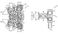
- FIG. 4shows a multi-level embodiment of an embodiment of an interspinous implant device according to the present invention.
- FIG. 5Ais a plan view of a distraction tool and locking/unlocking tool that are useable together in the performance of an implantation of a device according to the present invention.
- FIG. 5Bis a partial, cut-away view illustrating the locking functionality of lock arms of a distraction tool.
- FIG. 5Cis a perspective view of a device locked in a distraction tool and with a locking tool inserted.
- FIG. 5Dis a side view of the arrangement shown in FIG. 5C .
- FIG. 6illustrates use of tool 100 for insertion and initial placement of a device.
- FIG. 7Aillustrates a device having been inserted between the spinous processes, with the distal ends of the device arms having pierced the interspinous ligament.
- FIG. 7Billustrates a device having been successfully inserted between spinous processes, distracted to a desired height, and locked in position.
- FIG. 7Cillustrates an opposite side view of FIG. 7B .
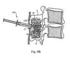
- FIG. 8Aillustrates implantation of a slurry of bone ingrowth material after placement of the device.
- FIG. 8Billustrates an optional step of placing bone ingrowth enhancing material on the opposite lateral side of the device and vertebrae.
- FIG. 9schematically illustrates another embodiment of a device according to the present invention.
- FIG. 10illustrates an alternative embodiment of a device according to the present invention.
- FIG. 11illustrates an alternative embodiment of a device according to the present invention.
- an inter-spinous spaceincludes a plurality of such inter-spinous spaces and reference to the “arm” includes reference to one or more arms and equivalents thereof known to those skilled in the art, and so forth.
- FIG. 1is a superior view of a vertebra 1 .
- the vertebral body 2is an anterior portion of the vertebra and is somewhat cylindrical in shape.
- the intervertebral disks(not shown) are interposed between adjacent vertebral bodies in the spine.
- Each vertebrahas two sets of facet joints 3 , 4 , at posterior locations. One pair faces upward (superior articular facets 3 ) and one downward (inferior articular facets 4 ). There is one joint on each side (right and left). Facet joints are hinge-like and link vertebrae together.
- a transverse process 5 and pedicle 6are located between the facets 3 , 4 and the vertebral body 2 . The transverse processes 5 serve for the attachment of muscles and ligaments.
- the laminae 7are plates of bone that form the posterior walls of each vertebra 2 , enclosing the spinal cord.
- the spinous process 8is directed backward and downward from the junction of the laminae 7 , and serves for the attachment of muscles and ligaments.
- FIG. 2is an illustration showing a lateral view of adjacent spinous processes 8 , 8 and a sectional view of the vertebral bodies 2 from the lumbar portion of the spine.
- FIG. 2further illustrates interspinous ligament 11 and supraspinous ligament 13 .
- Interspinous ligament 11connects the adjacent spinous processes and stretches vertically from the inferior border of the upper spinous process 8 shown to the superior border of the adjacent spinous process 8 below.
- Interspinous ligament 11interconnects adjacent spinous processes 8 in this manner with respect to all vertebrae, except those in the cervical spine, where it is absent.
- Supraspinous ligament 13extends along the posterior tips of the spinous processes 8 and blends with the ligamentum nuchae at its superior end. In elderly individuals and in persons who engage in heavy physical activity, the ligament can become ossified, making a midline approach to the epidural space impossible.
- FIG. 3Ashows an embodiment of an interspinous implant device 10 according to the present invention.
- Device 10includes a main body 12 .
- Main body 12includes a shaft 14 and bases 16 from which arms 18 extend transversely with respect to shaft 14 .
- Arms 18are substantially straight and typically extend perpendicularly with respect to the longitudinal axis L of shaft 14 , although slight variations in this angulation can be made for variations in the embodiment shown. In any case, arms 18 extend parallel to each other.
- FIG. 3Ashows device 10 in a closed configuration, in which the inner surfaces of arms 18 that face one another contact each other (as shown) or come into close approximation with each other, i.e., the closest configuration that arms can be positioned with respect to one another.
- arms 18can be brought together to a smallest possible height 20 to minimize the space required between spinous processes 8 , 8 to allow insertion of arms 18 , 18 therebetween, that is, to maximize the use of device 10 for one-step insertion between spinous processes in the largest percentage of cases, down to the smallest possible distances between adjacent spinous processes.
- each individual arm 18 and thus the overall height 20 of the arms in the closed configurationwill vary depending upon the location of the spine in which device 10 is to be inserted. However, the height 20 will be small enough to allow arms 18 to be inserted between the target spinous processes 8 where the device is desired to be implanted without the requirement for any distraction prior to this insertion. Further, height 20 in the closed configuration may be less than the distance between the two target spinous processes, or alternatively, equal or only slightly greater, such that the beveled tips of arms 18 slightly distract the spinous processes as arms 18 are inserted. Thus, device 10 can be provided in different sizes for application in different areas of the spine.
- the space between spinous processesis also greater in the lumbar region than in the cervical region, thereby permitting arms 18 to have greater height for devices to be implanted in the lumbar region, relative to arm heights of devices to be implanted in the cervical region.
- height 20 of arms 18 in the closed configurationis about 6 mm (i.e., each arm 18 having a height of about 3 mm), although this height may vary, as noted.
- arm heightsmay vary from about 1.5 mm to about 6 mm, or about 2 mm to about 5 mm, depending on the intended site of implantation, typically less than or equal to about 4 mm.
- cutouts 22may be formed and configured to receive the spinous processes 8 .
- cutout 22has a length 221 designed to match or slightly exceed the width of the portion of the spinous process received therein.
- the ends of cutout 22may be beveled to connect with the adjacent portions of arm 18 , or radiused or otherwise tapered to gradually transition to the full height of the arm.
- the ends of cutout 22can be substantially perpendicular to the lengthwise direction, wherein cutout 22 takes the form of a notch.
- cutouts 22are done away with altogether.
- cutouts 22are typically included to provide additional lateral stability. Regardless of the configuration that cutout 22 takes, the free end of arm 18 extends somewhat beyond the distal end of cutout 22 (end further from main body 12 ) so as to extend beyond the interspinous space when implanted, so that the protrusion extends from where the free end meets the distal end 22 d of cutout against arm 18 against the lateral surface of the spinous process 8 that is opposite the lateral surface of the spinous process 8 on the side from which device 10 is inserted. Likewise, the enlarged height of arm 18 proximal of the proximal end of cutout 22 acts as a stop or anchor against the lateral surface of the spinous process 8 that is on the side from which device 10 is inserted.
- the spinous processes 8are secured against lateral movements, and conversely, arms 18 are secured from sliding laterally with respect to the spinous processes 8 .
- Bases 16 and main body 12are positioned up against the side of spinous processes 8 to provide still further lateral stability of device 10 and the spinous processes 8 as distracted by device 10 .
- friction-enhancing surfaces 24may be provided on cutouts 22 to further facilitate anchoring the spinous processes.
- the partial view of FIG. 3Billustrates one embodiment of optional friction-enhancing surfaces 24 in the form of spikes.
- these surfaces 24could be provided as roughened surfaces, such a knurled surfaces, threaded surfaces, diamond-cut surfaces, or the like.
- the proximal end portions 18 p of arms 18can be flared, beveled or otherwise formed to have increased height, as these portions are not inserted between the spinous processes and thus do not have to be kept as thin as possible, and this provides additional support and structural rigidity where arms 18 connect to bases 16 .
- the length of arm 18will vary, depending upon the specific location where it is to be used (e.g., cervical spine, thoracic spine, or lumbar spine, for example), the size of the patient, as the vertebrae will vary in size based on this, and even the species of the patient, as device 10 is designed primarily for human patients, but could also be used in other vertebrates.
- a typical lengthwill include a length of about four mm to about six mm, for the portion extending distally from cutout 22 , plus the length of the cutout and a length of the portion of arm 18 between cutout 22 and base 16 extending about an additional ten mm to about twenty-five mm, for an overall length of about fourteen mm to about thirty-one mm, for use in the lumbar vertebrae.
- these lengthsmay be shorter for use in the cervical vertebrae as well as in the thoracic vertebrae, and may vary to be somewhat greater or lesser depending upon the anatomy of the individual patient being treated.
- Arms 18are separable from each other to form a maximum open configuration height up to about eight mm to about twenty mm, typically from about twelve mm to about fourteen mm, although, again this will vary depending upon the location of the spine into which the device 10 is implanted, among other factors. Since arms 18 are continuously variably adjustable, they can be fixed at any height between the closed configuration height and the maximum open configuration height as desired.
- the length of cutout 22will typically vary from about four mm to about eight mm for use in an adult male human patient, although these ranges could vary, with smaller ranges being normal for adult female human patients and even smaller ranges for pediatric patients.
- the free ends (also referred to as the distal ends or leading ends) 18 d of arms 18are tapered or beveled or otherwise geometrically configured to pierce the interspinous ligament 11 during insertion and to thereby facilitate installation and placement of device 10 between the spinous processes.
- the distal ends of arms 18may be tapered along more than one plane so as to resemble pencil points, or the like.
- arms 18in the closed configuration are inserted through interspinous ligament 11 and positioned between spinous processes 8 , preferably without distracting the spinal processes prior to inserting arms 18 , although a slight amount of distraction may be performed when the closed configuration height 20 is slightly greater than the height of the space between the adjacent spinous processes 8 .
- the superior base 16is integral with shaft 14
- the inferior base 16is slidable with respect to shaft 14 and lockable to fix it in a desired position with respect to shaft 14
- the superior integral base 16may be welded to shaft 16 or machined integrally therewith, or forged and machined as a single integral component.
- Shaft 14may have a flat side 14 f against which a lock can be forced to lock the position of the slidable base 16 /arm 18 relative thereto.
- the opening 16 h that is configured to slidingly mate with shaft 14may include a mating flat side 16 f so as to key base 16 to shaft 14 to prevent rotation of base 16 and arm 18 about the longitudinal axis L of shaft 14 .
- shaft 14may include depressions 14 d or through holes configured to receive a portion of a lock for enhanced prevention of sliding of the components in a vertical direction. Depressions of through holes 14 d are provided on/through the flat side 14 f when the flat side 14 f is present.
- FIG. 3Cis an exploded view of device 10 that illustrates the mating components for keying the inferior base 16 to shaft 14 .
- lock 24includes a set screw or locking screw 24 s having external threads that mate with internal threads in a threaded opening 16 t of base 16 .
- base 16is assembled (slid over) on shaft 14 , it is freely slidable along shaft 14 until locking screw 24 s is threaded into opening 16 t to an extent where the leading end of locking screw 24 s extends into opening 16 h and abuts against shaft 14 , e.g., at flat 14 f , and optionally, is received in depression or opening 14 d .
- device 10can be configured so that inferior base 16 /arm 18 is completely removable from shaft 14 when locking screw is in an unlocked position (i.e., not abutting against shaft 14 with sufficient force to prevent base 16 from being slid with respect to shaft 14 ), as base can be slid in the inferior direction until it slides off shaft 14 .
- a lip or other retainer 26may be optionally formed at the bottom end of shaft 14 to prevent base 16 from sliding off, even when in the unlocked configuration.
- tool engagement structures 28may be provided on each base for releasably locking a distraction tool thereto, as described in more detail below.
- tool engagement structures 28are formed by slots 28 .
- bosses 16 bmay be formed on the right sides of the bases 16 , such as illustrated in FIGS. 7A-7B , for example, in which case, the shaft flat 14 f and openings 16 f , if present, are also provided on the right side of the device 10 , as well as locking and tool engagement features.
- FIG. 3Dshows device 10 in an open or distracted configuration, in which the inferior arm 18 has been slid away from the superior arm 18 to form a gap therebetween and so that the contact surfaces 22 c of arms 18 (which, in the embodiment shown, are on cutouts 22 ) are separated by a distance of 20 d 1 .
- This separation distancecan be locked by locking the inferior arm 16 by torquing lock screw 24 s against shaft 14 in a manner as described above.
- inferior arm 18is continuously positionable and lockable at any location along shaft 14 (unless depressions or holes 14 d are provided, in which case a plurality of discrete, lockable positions are provided), so that the distance between contact surfaces 18 c is continuously variable and lockable between and including any distance from 20 c (see FIG. 3A) to 20 d 2 .
- device 10may be configured so that both bases 16 are slidable and lockable with respect to shaft 14 , in which case each base would include a lock 24 as described.
- These bases 16may be formed to both be completely removable by sliding them off shaft 14 , or one or both ends of shaft 14 may be provided with end stops, shoulders, lips or retainers 26 . Any of the other variations described above may also be included in these embodiments.
- FIG. 4shows a multi-level embodiment of an interspinous implant device 10 .
- main body 12is provided with an extended shaft having sufficient length on which to mount two pairs of bases 16 having arms 18 extending therefrom.
- two levels of distractionmay be implemented to the spine, a first between a first adjacent pair of spinous processes 8 , 8 and a second between a second pair of interspinous processes 8 , 8 , wherein both pairs of interspinous processes may have one member that is the same.
- the spinous process contacted on the superior surface by the inferior arm 18 of the superior pair of arms 18may be the same spinous process that is contacted on the inferior surface by the superior arm 18 of the inferior pair of arms 18 .
- the superior most base 16is integral with shaft 14 in the embodiment of FIG. 4 .
- the other three bases 16 /arms 18are slidable with respect to shaft 14 and lockable to shaft 14 via locks 24 .
- all bases 16may be slidable with respect to shaft 14 and provided with locks 24 .
- the inferior most base 16may be provided integrally with shaft 14 , while the other three bases 6 /arms 18 are slidable with respect to shaft 14 and lockable to shaft 14 via locks 24 .
- FIG. 5Ais a plan view of a distraction tool 100 and locking/unlocking tool 150 that are useable together in the performance of an implantation of a device 10 according to the present invention.
- Distraction tool 100includes first and second distraction arms 102 at a distal portion thereof, which may form a pair, and which are configured to move apart from and toward each other in the directions of the arrows shown.
- distraction arms 102are pivotally connected at a pivot joint 104 intermediate of distal and proximal ends of tool 100 .
- Driving arms 106extend proximally from distraction arms 102 at the location of pivot joint 104 and are movable toward one another by an operator in order to drive distraction arms 102 apart.
- driving arms 106are integrally formed with their respective distraction arms and form the proximal portions of the integral arms, while distraction arms 102 form the distal portions of the integral arms.
- the integral armsform a wishbone configuration when the distraction arms 102 are in the closed configuration, although toll 100 is not limited to this styling, as long as proximal driving arms are provided to drive distal distraction arms in a manner such as described.
- Driving arms 106may be biased apart to the closed configuration (wherein the closed configuration refers to the configuration of the distal, distraction arm members 102 , which, in the closed configuration shown in FIG. 5A , drive or maintain the device arms 18 to or in the closed configuration), as illustrated in FIG. 5A , by biasing mechanism 108 , which may be an arrangement of leaf springs, a single leaf spring, one or more coil springs, or other biasing arrangement, as would be apparent to those of ordinary skill in the mechanical arts.
- biasing mechanism 108which may be an arrangement of leaf springs, a single leaf spring, one or more coil springs, or other biasing arrangement, as would be apparent to those of ordinary skill in the mechanical arts.
- a distraction lock mechanism 110may be provided to maintain the distraction arms 102 apart by the distance driven by movement together of driving arms 106 .
- the driving arm 106 shown at the left sideratchets against a toothed rack 112 and is therefore held in position relative to the other driving arm as it is advanced toward it. This facilitates maintaining device 10 under the desired amount of distraction until the slidable arm or arms 18 can be locked in position by torquing lock screw 24 against shaft 14 as described above.
- the operatorcan release the driving arms 106 to allow them to be moved apart by rotating rack arm 112 about pivot joint 114 in the direction indicated by the rotational arrow in FIG. 5A .
- rack arm 112can be release wherein it counter-rotates to again perform the locking function described.
- Each distraction arm 102has an opening in its distal end of distal end portions 102 d that is configured to mate with a base 16 of device 10 .
- each basehas a portion that extends away from the shaft to form a boss 16 b .
- the distal end portions 102 d of distraction arms 102are tubular to slide over these bosses 16 b with a close fit, but still allowing the arms 102 to slide freely over the bosses 16 b .
- Lock arms 116are provided with cammed or eccentric distal end pieces 116 c that are configured to lock into tool engagement structures 28 .
- FIG. 5Bis a partial, cut-away view that illustrates this.
- FIG. 5Cis a perspective view of device 10 locked in tool 100 as described. Note that although locking tool 150 is shown in both FIGS. 5A and 5C , that it is removable from distraction tool 100 and typically will not be in place when distraction tool 100 is initially mounted on device 10 .
- locking tool 150is inserted only after distraction tool 100 has been used to distract arms 18 apart to distract the spinous processes 8 apart to, or near to, the desired amount of distraction. This provides the surgeon with maximum visualization of the spinous processes and interspinous ligament 11 , while performing piercing of the ligament, insertion/placement of device 10 and distraction of device arms 18 and spinous processes 8 .
- each distraction arm 102is offset from the longitudinal axis LD 1 of the remainder of the distraction arm along a longitudinal axis LD 2 that is parallel to LD 1 , as illustrated in FIGS. 5C-5D .
- the side view of FIG. 5Dshows the clear pathway that is established for tool 150 by offsetting the distal end portions 102 d , while still maintaining a low profile tool 100 .
- Implantation of device 10is relatively simple compared to presently available products and can be performed as a minimally invasive procedure. It can be placed using a small unilateral incision, typically where the incision is about the same length as, or less than the height of shaft 14 , and, since access to only one side of the spinal processes is required, greatly reduces the morbidity and time required to perform the implantation. Further, when a device fitted with multiple sets of arms 18 is used to treat two or three stenotic levels, for example, this results in an even greater time saving and reduction in pain, morbidity and recovery time.
- the surgeondetermines the best approach (i.e., from which side of the spinous processes 8 ), and size of device 10 to be used, typically with the aid of radiographic imaging.
- the distraction tool 100is prepared by locking closed the arms 102 relative to rack 112 .
- the device 10 selected as the correctly sized devicecan be safety-checked to ensure that the slidable body 16 is freely slidable over shaft 14 when in the unlocked configuration.
- Device 10is then locked to distraction tool 100 by inserting bosses 16 b into the cavities in distal ends 102 d and locking them therein as described herein.
- dissectionis performed to provide lateral access to the spinal processes 8 , 8 and interspinous ligament 11 from one side only.
- device 10will have been mounted on tool 100 and locked in place in the closed configuration as shown in FIG. 6 and in a manner as described above.
- Device 10is then inserted through the incision 202 , using tool 100 , and the distal/free ends of arms 18 are approximated to the interspinous ligament joining the two target spinous processes, from a lateral approach, as illustrated in FIG. 6 .
- Tool 100is then used to drive the free ends of arms 18 through the interspinous ligament 11 , thereby piercing it, but preserving the interspinous ligament intact between the processes 8 . Also, the supraspinous ligament may be left intact and need not even be pierced or altered. Thus, free ends of arms 18 extend out of the opposite side of the interspinous space between spinous processes 8 , 8 , beyond ligament 11 . It is noted that device 10 is designed to be placed between the interspinous processes without the need for any preliminary distraction, prior to insertion of device 10 . However, in the unlikely situation where there is not enough space to insert device 10 initially between spinous processes, one or more dilators may be used to perform preliminary dilation in one or more iterative dilation steps. FIG.
- FIG. 7Aillustrates device 10 having been inserted between the spinous processes 8 , with the distal ends of arms 18 having pierced the interspinous ligament.
- tool 100will still be locked to device 10 , but tool 100 is not shown in FIG. 7A for clarity of illustration of device 10 relative to the anatomy.
- locking tool 150may optionally be inserted into a distal end portion 102 that is joined with a slidably adjustable base 16 .
- insertion of locking tool 150can be inserted earlier in the process.
- distraction of the spinous processesis performed first, by distracting arms 18 apart using tool 100 , and once the desired amount of distraction has been reached or approximated, locking tool 150 is then inserted.
- tool 100is manipulated to squeeze drive arms 106 together so as to drive arms 18 of device apart, via distraction arms 102 in a manner described above.
- an indicator 120may be provided on the proximal end portion of tool 120 , that can be viewed by the user to tell the user the precise amount of distraction as the distance between arms 106 is varied to vary the amount of distraction.
- an indicator needle 120 ais provided to extend from one of the drive arms 106 to indicate the amount of distraction where it aligns with graded markings 120 b along rack 112 .
- distraction amountsmay be in the range of about three to about fifteen millimeters, or about five to about fifteen millimeters, or from the height of the arms in the closed configuration up to about twenty-two millimeters, for example, although these ranges may vary depending on, but not limited to the factors mentioned above.
- the distraction providedis a controlled, gradual retraction since the arms 18 of device 10 can be spread gradually, smoothly, and as slowly as desired.
- tool 150is used to lock movable base 16 against shaft 14 to maintain arms 18 in their current configuration. Lock arms 116 can then be reverse rotated to unlock tool 100 from device 10 and tool 100 and tool 150 can be removed together. Alternatively, tool 150 can be removed prior to removing tool 100 .
- Tool 150has a shaft 152 and a handle 154 that can be torqued by the user to effect a locking or unlocking of the lock 24 on base 16 . Shaft 152 preferably exceeds the length of tool 100 so that handle 154 can be torqued without interference from tool 100 .
- the distal end of tool 150is configured to mechanically mate with locking screw 24 s to provide the torquing forces necessary to lock locking screw against shaft 14 or to release locking screw 24 s from contact with shaft 14 , thereby unlocking base 16 and allowing it to slide with respect to shaft 14 .
- locking screwmay be provided with a female hex head and the distal end of tool 150 would then be provided with a mating hexagonal male configuration.
- Other screw head mating configurationsmay be substituted, as well as other mating mechanical configurations, as would be readily apparent to those of ordinary skill in the mechanical arts.
- FIG. 7Billustrates device 10 having been successfully inserted between spinous processes 8 , distracted to a desired height, and locked in position, in a manner as described above.
- FIG. 7Bshows device 10 after removal of the implantation tools, after which the surgical site can be closed to complete the procedure, leaving device 10 in position as shown in FIG. 7B .
- FIG. 7Cillustrates an opposite side view of FIG. 7B , wherein the distal end portions 18 d of arms 18 are shown protruding through the opposite side of the interspinous ligament and arms 18 are distracting the interspinous processes apart by a desired amount.
- the procedureis similar, although a slightly longer incision 202 may need to be placed.
- the one or more pairs of arms 18 /bases 16 that are not initially locked to tool 100must be locked against shaft 14 in the closed configuration, at a distance/distances from the pair of bases that are locked into tool 100 so as to align with the appropriate interspinous spaces into which they are to be placed.
- Each pair of arms 18can then be driven sequentially into the respective target interspinous space using tool 100 .
- Distractionmay be performed at the time of placing each respective pair of arms, or the surgeon may wait until all pairs of arms have been pierced through the interspinous ligaments 11 in the respective target interspinous spaces, and then go back and perform the distraction of each pair of arms 18 sequentially.
- a still further alternativeis to lock multiple tools to a multi level device 10 , where each pair of arms 18 are locked to an individual tool 100 .
- tool 100may have multiple sets of arms 102 , each set being lockable to a respective level (i.e., pair of arms 18 ) of the device 10 , prior to insertion of the device.
- the respective sets of armsare movable with respect to one another in a direction along the longitudinal axis of shaft 14 .
- tools 100 and 150are removed and the patient is closed up (including closing the incision 202 ) to complete the procedure.
- the sitecan be re-entered to adjust one or more distraction levels, by locking tool 100 against the bosses 16 b of the bases from which the arms 18 to be adjusted extend, and then using tool 150 to unlock a base 16 and adjust the amount of distraction as desired.
- the base 16can then be relocked and the tools can be removed and the patient closed, in the same manner as described previously.
- Device 10can also be removed, if desired, by entering the patient in the same manner described above, and locking tool 100 to device 10 .
- Tool 150is then used to unlock base 16 and tool 100 is used to retract arms 18 back together to the closed position.
- Base 16is then relocked to maintain the arms 18 in the locked configuration and tool 150 is used to pull (retract) device out from between the spinous processes 8 .
- Tool 100 and device 10can then together be removed from the patient and the patient can be closed to finish the procedure.
- another device 10may be implanted to replace the device 10 that was removed.
- device 10may be used in the performance of a fusion procedure.
- device 10is implanted in any of the same manners described above.
- the device implantation tools 100 , 150can be removed and portion of the lamina 7 and spinous processes 8 may optionally be decorticated, using a high speed burr, for example, to encourage bone growth/regeneration/healing process, and a protein substance, such as bone morphogenetic protein (BMP), one or more bone grafts (either solid or particulate) or other bone growth enhancing material or agent 30 is implanted into the surgical site to contact at least a portion of device 10 and portions of both of the vertebrae 1 spanned by device 10 as well as lamina 7 .
- BMPbone morphogenetic protein
- Portions or all of device 10may be covered/encapsulated by the bone growth enhancing material 30 , with material 30 also contacting and covering at least portions of the spinous processes 8 that are contacted by device 10 and/or laminae 7 of those same vertebrae 7 .
- the soft tissues surrounding the bone growth enhancing material 30maintains the material 30 in place to allow tissue ingrowth to proceed in the desired locations.
- FIG. 8Aillustrates implantation of a slurry of bone ingrowth material 30 after placement of device 10 .
- the slurryis delivered via a delivery device 160 having a tube 162 that contains the slurry and a piston/plunger component 164 used to drive the material 30 out of the larger bore distal end of tube 162 when the distal end has been placed in the surgical site at a location where it is desired to deliver the bone ingrowth enhancing material 30 .
- Tool 160may be very similar to a standard syringe, for example, but with an open bore at the distal end, so that the distal opening has an inside diameter the same, or only slightly smaller than the inside diameter of the tube 162 .
- the materialcan be spread using a spatula or other similar tool (not shown) if desired to facilitate further placement as desired.
- the material 130By filling the space with the material 130 , it remains packed in place once the surgical site is closed.
- solid ingrowth materials 30such as bone grafts, plates or the like may be implanted additionally, or alternatively to the particulate material. After completion of the implantation of the ingrowth enhancing material(s) 30 , the site is closed around the materials, to maintain them relatively motionless to enhance the ingrowth of bone tissue therein.
- bone ingrowth enhancing material 30may also be implanted, by opposite lateral side of the device 10 and vertebrae 1 , as illustrated in FIG. 8B .
- This placement of the material 30 on the opposite sidemay be performed similar to that performed on the first side, with the material contacting and at least partially covering the distal end portions 18 and the spinous processes 8 and/or laminae 7 .
- the placement of the materialmay be performed using minimally invasive techniques, such as by using tool 160 for delivery of slurry or particulate material 30 , with or without further spreading with a spatula or the like. Delivery of material 30 to both side of the device 10 and vertebrae 1 can be performed from the single entry incision having been established at the beginning of the implantation procedure.
- the lamina on the opposite sidewould also need to be exposed and prepared to facilitate a healing response such as with a high speed burr or the like, as described above.
- device 10after closure of the surgical site, device 10 maintains the spinal processes 8 a fixed distance apart, and by immobilizing the spinal processes by providing posterior fixation, this decreases spinal segment motion and allows bone ingrowth to occur to fuse the adjacent vertebrae and device 10 together.
- FIG. 9schematically illustrates an alternative embodiment of a device 10 . While the example shown is a multi-level distraction implant device for distracting adjacent pairs of adjacently opposed spinous processes 8 , a single level device 10 may also be provided using similar construction, but only one pair of arms 18 for distraction a single pair of spinous processes. Also, like the embodiments described previously, device 10 may be configured to distract between two or more non-adjacent pairs of adjacently opposed spinous processes 8 . Each pair of arms in this embodiment has one arm 18 that extends directly from shaft 14 of main body 12 , while the other arm 18 of the pair extends from base 16 .
- Drivers 124are provided and configured to be torqued by a driving tool (e.g., such as tool 150 , for example) to drive arms 18 toward each other or apart from each other, depending upon the direction of torquing.
- a driving toole.g., such as tool 150 , for example
- Each pair of armsis driven by a separate driver 124 , respectively.
- Driver 124may be threadably engaged with gearing 125 , such as racking and pinion, a worm gear, splines or other gearing arrangement, for example.
- Gearing 125engages with threading, rack, etc, on shaft 14 so that as driver 124 is torqued, gearing 125 translates this torque to shaft 14 to move it either up or down with respect to the base 16 into which it is inserted, and consequently either driving arms 18 apart or towards one another.
- Device 10is inserted laterally so that each pair of arms 18 pierces through the interspinous ligament 11 in the interspinous space between the spinous processes to be distracted.
- these alternative devicescan be used in the performance of a fusion, using bone ingrowth enhancing material 30 in any of the manners described above.
- FIG. 10illustrates an alternative embodiment of device 10 , in which device 10 includes bases 16 that slide on shaft 14 in the same manner and using the same mechanisms as those described above with regard to the embodiments described in FIGS. 3A-8B .
- arms 18are hooks that are substantially curved or “hook-shaped”.
- FIG. 10illustrates hooks 18 having been inserted through the interspinous ligaments 11 at adjacent levels of the vertebrae, between spinous processes 8 .
- a multi-level distractionis illustrated in FIG. 10 , with a spinous process 8 being positioned between the hooks 18 .
- one or more dilatorsmay be used to perform preliminary dilation/distraction in one or more iterative dilation steps, prior to insertion of the hooks 18 between spinous processes 8 .
- beveled tip portions 18 tmay be provided at the distal ends of hooks 18 in order to better align the distal tips of hooks 18 with the spaces between the spinous processes, and to provide a small-cross sectional area tip on each hook to perform the initial piercing through the interspinous ligament.
- Each beveled tip 18 textends in a direction away from the curvature of the hook 18 that it extends from and toward the opposite hook 18 , so that the distal end of tips 18 t are much closer to one another than the ends of the hooks from which they extend.
- the beveled portions of tips 18 tthen act to perform some distraction as tips 18 t are passed between the spinous processes, thereby guiding hooks 18 into positions between the spinous processes 8 .
- Device 10may then be adjusted to perform the desired amount of multi-level distraction using the same techniques and tools described above. The procedure can then be completed at this stage, once arms 18 have been locked at the desired relative positions.
- device 10can be used in the performance of a fusion, using bone ingrowth enhancing material 30 in any of the manners described above, as illustrated in FIG. 10 .
- FIG. 11illustrates an alternative embodiment of device 10 , in which device 10 includes bases 16 that slide on shaft 14 in the same manner and using the same mechanisms as those described above with regard to the embodiments described in FIGS. 3A-8B .
- arms 18are hooks that are substantially curved or “hook-shaped”, and rather than being aligned so that that abut one another in the closed configuration like arms 18 of FIG. 3A , hooks 18 are slightly offset to allow hooks 18 to slide past one another in the closed configuration shown in FIG. 11 . This greatly reduces the height 20 in the closed configuration, relative to what it would be if hooks 18 were aligned to abut one another in the closed configuration.
- device 10 of FIG. 11makes it possible to use device 10 at a single level, i.e., where no spinous processes 8 are positioned between the adjacent hooks.
- device 10 of FIG. 11can be inserted and used in any of the same manners described above with regard to FIGS. 3A-8B .
- one or more dilatorsmay be used to perform preliminary dilation/distraction in one or more iterative dilation steps, prior to insertion of the hooks 18 between spinous processes 8 .
- beveled tip portions 18 tmay be provided at the distal ends of hooks 18 in order to better align the distal tips of hooks 18 with the space between the spinous processes, and to provide a small-cross sectional area tip on each hook to perform the initial piercing through the interspinous ligament.
- Each beveled tip 18 textends distally in a direction away from the curvature of the hook 18 that it extends from and toward the opposite hook 18 , so that the distal ends of tips 18 t are much closer to one another than the ends of the hooks from which they extend and are very close together when hooks 18 are in the closed configuration shown in FIG.
Landscapes
- Health & Medical Sciences (AREA)
- Orthopedic Medicine & Surgery (AREA)
- Life Sciences & Earth Sciences (AREA)
- Neurology (AREA)
- Surgery (AREA)
- Heart & Thoracic Surgery (AREA)
- Engineering & Computer Science (AREA)
- Biomedical Technology (AREA)
- Nuclear Medicine, Radiotherapy & Molecular Imaging (AREA)
- Medical Informatics (AREA)
- Molecular Biology (AREA)
- Animal Behavior & Ethology (AREA)
- General Health & Medical Sciences (AREA)
- Public Health (AREA)
- Veterinary Medicine (AREA)
- Prostheses (AREA)
Abstract
Description
Claims (20)
Priority Applications (2)
| Application Number | Priority Date | Filing Date | Title |
|---|---|---|---|
| US11/897,282US8974496B2 (en) | 2007-08-30 | 2007-08-30 | Interspinous implant, tools and methods of implanting |
| PCT/US2007/026266WO2008085445A2 (en) | 2007-01-05 | 2007-12-24 | Interspinous implant, tools and methods of implanting |
Applications Claiming Priority (1)
| Application Number | Priority Date | Filing Date | Title |
|---|---|---|---|
| US11/897,282US8974496B2 (en) | 2007-08-30 | 2007-08-30 | Interspinous implant, tools and methods of implanting |
Publications (2)
| Publication Number | Publication Date |
|---|---|
| US20090062918A1 US20090062918A1 (en) | 2009-03-05 |
| US8974496B2true US8974496B2 (en) | 2015-03-10 |
Family
ID=40408714
Family Applications (1)
| Application Number | Title | Priority Date | Filing Date |
|---|---|---|---|
| US11/897,282Expired - Fee RelatedUS8974496B2 (en) | 2007-01-05 | 2007-08-30 | Interspinous implant, tools and methods of implanting |
Country Status (1)
| Country | Link |
|---|---|
| US (1) | US8974496B2 (en) |
Cited By (1)
| Publication number | Priority date | Publication date | Assignee | Title |
|---|---|---|---|---|
| US20170215926A1 (en)* | 2016-02-02 | 2017-08-03 | Globus Medical, Inc. | Expandable spinal fixation system |
Families Citing this family (41)
| Publication number | Priority date | Publication date | Assignee | Title |
|---|---|---|---|---|
| US8241330B2 (en) | 2007-01-11 | 2012-08-14 | Lanx, Inc. | Spinous process implants and associated methods |
| US9055981B2 (en) | 2004-10-25 | 2015-06-16 | Lanx, Inc. | Spinal implants and methods |
| WO2006058221A2 (en) | 2004-11-24 | 2006-06-01 | Abdou Samy M | Devices and methods for inter-vertebral orthopedic device placement |
| US9265532B2 (en) | 2007-01-11 | 2016-02-23 | Lanx, Inc. | Interspinous implants and methods |
| US9247968B2 (en) | 2007-01-11 | 2016-02-02 | Lanx, Inc. | Spinous process implants and associated methods |
| US7842074B2 (en) | 2007-02-26 | 2010-11-30 | Abdou M Samy | Spinal stabilization systems and methods of use |
| US8308767B2 (en)* | 2007-09-19 | 2012-11-13 | Pioneer Surgical Technology, Inc. | Interlaminar stabilization system |
| US8940019B2 (en)* | 2007-12-28 | 2015-01-27 | Osteomed Spine, Inc. | Bone tissue fixation device and method |
| US8313512B2 (en)* | 2008-03-26 | 2012-11-20 | Depuy Spine, Inc. | S-shaped interspinous process spacer having tight access offset hooks |
| US8343190B1 (en) | 2008-03-26 | 2013-01-01 | Nuvasive, Inc. | Systems and methods for spinous process fixation |
| US8025678B2 (en)* | 2008-03-26 | 2011-09-27 | Depuy Spine, Inc. | Interspinous process spacer having tight access offset hooks |
| EP2323574B1 (en) | 2008-08-13 | 2012-02-15 | Synthes GmbH | Interspinous spacer assembly |
| EP2445428A2 (en) | 2009-06-23 | 2012-05-02 | Osteomed Spine, Inc. | Bone tissue clamp |
| US8636772B2 (en) | 2009-06-23 | 2014-01-28 | Osteomed Llc | Bone plates, screws, and instruments |
| US8721686B2 (en)* | 2009-06-23 | 2014-05-13 | Osteomed Llc | Spinous process fusion implants and insertion, compression, and locking instrumentation |
| BR112012003050A2 (en) | 2009-08-10 | 2019-09-24 | Osteomed Llc | bone plate assembly, bone surface attachment plate, cushion and bone plate |
| US10098674B2 (en) | 2009-10-22 | 2018-10-16 | Nuvasive, Inc. | System and method for posterior cervical fusion |
| US9204906B2 (en) | 2009-10-22 | 2015-12-08 | Nuvasive, Inc. | Posterior cervical fusion system and techniques |
| US8764806B2 (en) | 2009-12-07 | 2014-07-01 | Samy Abdou | Devices and methods for minimally invasive spinal stabilization and instrumentation |
| US8876866B2 (en)* | 2010-12-13 | 2014-11-04 | Globus Medical, Inc. | Spinous process fusion devices and methods thereof |
| US9149306B2 (en) | 2011-06-21 | 2015-10-06 | Seaspine, Inc. | Spinous process device |
| USD757943S1 (en) | 2011-07-14 | 2016-05-31 | Nuvasive, Inc. | Spinous process plate |
| US8882805B1 (en) | 2011-08-02 | 2014-11-11 | Lawrence Maccree | Spinal fixation system |
| US8845728B1 (en) | 2011-09-23 | 2014-09-30 | Samy Abdou | Spinal fixation devices and methods of use |
| US11812923B2 (en) | 2011-10-07 | 2023-11-14 | Alan Villavicencio | Spinal fixation device |
| US20130226240A1 (en) | 2012-02-22 | 2013-08-29 | Samy Abdou | Spinous process fixation devices and methods of use |
| US10448977B1 (en) | 2012-03-31 | 2019-10-22 | Ali H. MESIWALA | Interspinous device and related methods |
| US8771277B2 (en) | 2012-05-08 | 2014-07-08 | Globus Medical, Inc | Device and a method for implanting a spinous process fixation device |
| US9138325B2 (en)* | 2012-07-11 | 2015-09-22 | Globus Medical, Inc. | Lamina implant and method |
| US9198767B2 (en) | 2012-08-28 | 2015-12-01 | Samy Abdou | Devices and methods for spinal stabilization and instrumentation |
| EP2722021B1 (en) | 2012-10-20 | 2017-12-13 | K2M, Inc. | Lateral distractor |
| US9320617B2 (en) | 2012-10-22 | 2016-04-26 | Cogent Spine, LLC | Devices and methods for spinal stabilization and instrumentation |
| US9668786B2 (en)* | 2012-11-16 | 2017-06-06 | Southern Spine, Llc | Linkage systems for interspinous process spacing device |
| US9168073B2 (en) | 2013-03-15 | 2015-10-27 | DePuy Synthes Products, Inc. | Spinous process fixator |
| US10857003B1 (en) | 2015-10-14 | 2020-12-08 | Samy Abdou | Devices and methods for vertebral stabilization |
| US10744000B1 (en) | 2016-10-25 | 2020-08-18 | Samy Abdou | Devices and methods for vertebral bone realignment |
| US10973648B1 (en) | 2016-10-25 | 2021-04-13 | Samy Abdou | Devices and methods for vertebral bone realignment |
| EP3579772B1 (en)* | 2017-02-10 | 2023-06-28 | Zimmer Biomet CMF And Thoracic, LLC | Pectus bar and stabilizer devices |
| AU2018230818B2 (en) | 2017-03-08 | 2020-12-17 | Zimmer Biomet CMF and Thoracic, LLC | Pectus bar support devices |
| US11179248B2 (en) | 2018-10-02 | 2021-11-23 | Samy Abdou | Devices and methods for spinal implantation |
| CN115778629B (en)* | 2023-02-07 | 2023-04-25 | 四川大学华西医院 | supraspinous interspinous compound ligament |
Citations (191)
| Publication number | Priority date | Publication date | Assignee | Title |
|---|---|---|---|---|
| US3875595A (en) | 1974-04-15 | 1975-04-08 | Edward C Froning | Intervertebral disc prosthesis and instruments for locating same |
| US4309777A (en) | 1980-11-13 | 1982-01-12 | Patil Arun A | Artificial intervertebral disc |
| US4349921A (en) | 1980-06-13 | 1982-09-21 | Kuntz J David | Intervertebral disc prosthesis |
| US4369769A (en) | 1980-06-13 | 1983-01-25 | Edwards Charles C | Spinal fixation device and method |
| US4401112A (en) | 1980-09-15 | 1983-08-30 | Rezaian Seyed M | Spinal fixator |
| US4404967A (en)* | 1982-01-18 | 1983-09-20 | Wyzsza Szkola Inzynierska Im. Jurija Gagarina | Surgical strut for treatment of the back-bone |
| US4448191A (en) | 1981-07-07 | 1984-05-15 | Rodnyansky Lazar I | Implantable correctant of a spinal curvature and a method for treatment of a spinal curvature |
| US4479491A (en) | 1982-07-26 | 1984-10-30 | Martin Felix M | Intervertebral stabilization implant |
| US4501269A (en) | 1981-12-11 | 1985-02-26 | Washington State University Research Foundation, Inc. | Process for fusing bone joints |
| US4553273A (en) | 1983-11-23 | 1985-11-19 | Henry Ford Hospital | Vertebral body prosthesis and spine stabilizing method |
| US4554914A (en) | 1983-10-04 | 1985-11-26 | Kapp John P | Prosthetic vertebral body |
| US4599084A (en) | 1983-05-24 | 1986-07-08 | American Hospital Supply Corp. | Method of using biological tissue to promote even bone growth |
| US4599086A (en) | 1985-06-07 | 1986-07-08 | Doty James R | Spine stabilization device and method |
| US4604995A (en) | 1984-03-30 | 1986-08-12 | Stephens David C | Spinal stabilizer |
| US4611582A (en) | 1983-12-27 | 1986-09-16 | Wisconsin Alumni Research Foundation | Vertebral clamp |
| US4636217A (en) | 1985-04-23 | 1987-01-13 | Regents Of The University Of Minnesota | Anterior spinal implant |
| US4643178A (en) | 1984-04-23 | 1987-02-17 | Fabco Medical Products, Inc. | Surgical wire and method for the use thereof |
| US4653481A (en) | 1985-07-24 | 1987-03-31 | Howland Robert S | Advanced spine fixation system and method |
| US4657550A (en) | 1984-12-21 | 1987-04-14 | Daher Youssef H | Buttressing device usable in a vertebral prosthesis |
| US4685447A (en) | 1985-03-25 | 1987-08-11 | Pmt Corporation | Tissue expander system |
| US4696290A (en) | 1983-12-16 | 1987-09-29 | Acromed Corporation | Apparatus for straightening spinal columns |
| US4714469A (en) | 1987-02-26 | 1987-12-22 | Pfizer Hospital Products Group, Inc. | Spinal implant |
| US4743256A (en) | 1985-10-04 | 1988-05-10 | Brantigan John W | Surgical prosthetic implant facilitating vertebral interbody fusion and method |
| US4772287A (en) | 1987-08-20 | 1988-09-20 | Cedar Surgical, Inc. | Prosthetic disc and method of implanting |
| US4790303A (en) | 1987-03-11 | 1988-12-13 | Acromed Corporation | Apparatus and method for securing bone graft |
| US4834757A (en) | 1987-01-22 | 1989-05-30 | Brantigan John W | Prosthetic implant |
| SU1484348A1 (en) | 1987-03-04 | 1989-06-07 | Белорусский научно-исследовательский институт травматологии и ортопедии | Spinal column fixing device |
| US4863476A (en) | 1986-08-29 | 1989-09-05 | Shepperd John A N | Spinal implant |
| WO1990000037A1 (en) | 1988-06-28 | 1990-01-11 | Michelson Gary K | Artificial spinal fusion implants |
| US4904261A (en) | 1987-08-06 | 1990-02-27 | A. W. Showell (Surgicraft) Limited | Spinal implants |
| US4913134A (en) | 1987-07-24 | 1990-04-03 | Biotechnology, Inc. | Spinal fixation system |
| US4932975A (en) | 1989-10-16 | 1990-06-12 | Vanderbilt University | Vertebral prosthesis |
| US4936848A (en) | 1989-09-22 | 1990-06-26 | Bagby George W | Implant for vertebrae |
| US4946378A (en) | 1987-11-24 | 1990-08-07 | Asahi Kogaku Kogyo Kabushiki Kaisha | Artificial intervertebral disc |
| US4961740A (en) | 1988-10-17 | 1990-10-09 | Surgical Dynamics, Inc. | V-thread fusion cage and method of fusing a bone joint |
| US4969888A (en) | 1989-02-09 | 1990-11-13 | Arie Scholten | Surgical protocol for fixation of osteoporotic bone using inflatable device |
| US5011484A (en) | 1987-11-16 | 1991-04-30 | Breard Francis H | Surgical implant for restricting the relative movement of vertebrae |
| US5015247A (en) | 1988-06-13 | 1991-05-14 | Michelson Gary K | Threaded spinal implant |
| US5030220A (en) | 1990-03-29 | 1991-07-09 | Advanced Spine Fixation Systems Incorporated | Spine fixation system |
| US5035716A (en) | 1987-12-07 | 1991-07-30 | Downey Ernest L | Replacement disc |
| US5047055A (en) | 1990-12-21 | 1991-09-10 | Pfizer Hospital Products Group, Inc. | Hydrogel intervertebral disc nucleus |
| US5055104A (en) | 1989-11-06 | 1991-10-08 | Surgical Dynamics, Inc. | Surgically implanting threaded fusion cages between adjacent low-back vertebrae by an anterior approach |
| US5059193A (en) | 1989-11-20 | 1991-10-22 | Spine-Tech, Inc. | Expandable spinal implant and surgical method |
| US5059194A (en) | 1990-02-12 | 1991-10-22 | Michelson Gary K | Cervical distractor |
| WO1991016018A1 (en) | 1989-02-03 | 1991-10-31 | Francis Henri Breard | Flexible intervertebral stabilizer, and method and apparatus for determining or controlling its tension before it is placed on the back bone |
| US5084049A (en) | 1989-02-08 | 1992-01-28 | Acromed Corporation | Transverse connector for spinal column corrective devices |
| US5116334A (en) | 1988-12-21 | 1992-05-26 | Zimmer, Inc. | Posterior spinal system and method |
| US5123926A (en) | 1991-02-22 | 1992-06-23 | Madhavan Pisharodi | Artificial spinal prosthesis |
| US5129899A (en) | 1991-03-27 | 1992-07-14 | Smith & Nephew Richards Inc. | Bone fixation apparatus |
| US5147359A (en) | 1988-12-21 | 1992-09-15 | Zimmer, Inc. | Spinal hook body |
| US5154718A (en) | 1988-12-21 | 1992-10-13 | Zimmer, Inc. | Spinal coupler assembly |
| US5167662A (en) | 1992-01-24 | 1992-12-01 | Zimmer, Inc. | Temporary clamp and inserter for a posterior midline spinal clamp |
| US5180381A (en) | 1991-09-24 | 1993-01-19 | Aust Gilbert M | Anterior lumbar/cervical bicortical compression plate |
| US5192327A (en) | 1991-03-22 | 1993-03-09 | Brantigan John W | Surgical prosthetic implant for vertebrae |
| FR2681525A1 (en) | 1991-09-19 | 1993-03-26 | Medical Op | Device for flexible or semi-rigid stabilisation of the spine, in particular of the human spine, by a posterior route |
| US5201734A (en) | 1988-12-21 | 1993-04-13 | Zimmer, Inc. | Spinal locking sleeve assembly |
| US5236456A (en)* | 1989-11-09 | 1993-08-17 | Osteotech, Inc. | Osteogenic composition and implant containing same |
| US5258031A (en) | 1992-01-06 | 1993-11-02 | Danek Medical | Intervertebral disk arthroplasty |
| US5263953A (en) | 1991-12-31 | 1993-11-23 | Spine-Tech, Inc. | Apparatus and system for fusing bone joints |
| US5290312A (en) | 1991-09-03 | 1994-03-01 | Alphatec | Artificial vertebral body |
| US5304178A (en) | 1992-05-29 | 1994-04-19 | Acromed Corporation | Sublaminar wire |
| US5306309A (en) | 1992-05-04 | 1994-04-26 | Calcitek, Inc. | Spinal disk implant and implantation kit |
| US5330473A (en) | 1993-03-04 | 1994-07-19 | Advanced Spine Fixation Systems, Inc. | Branch connector for spinal fixation systems |
| WO1994021185A1 (en) | 1993-03-24 | 1994-09-29 | University Of Miami | Implantable spinal assist device |
| US5352225A (en) | 1993-01-14 | 1994-10-04 | Yuan Hansen A | Dual-tier spinal clamp locking and retrieving system |
| WO1994026192A1 (en) | 1993-05-07 | 1994-11-24 | Paccagnella Jean Gilbert | Linking device for an osteosynthesis strip, especially for insertion in the spine |
| FR2707864A1 (en) | 1993-07-23 | 1995-01-27 | Taylor Jean | Surgical clamp for tensioning an osteosynthesis ligament |
| US5387213A (en) | 1991-02-05 | 1995-02-07 | Safir S.A.R.L. | Osseous surgical implant particularly for an intervertebral stabilizer |
| US5390683A (en) | 1991-02-22 | 1995-02-21 | Pisharodi; Madhavan | Spinal implantation methods utilizing a middle expandable implant |
| US5393036A (en)* | 1989-11-17 | 1995-02-28 | Sheridan; Thomas L. | Continuously engaged tangential driving tool |
| US5395372A (en) | 1993-09-07 | 1995-03-07 | Danek Medical, Inc. | Spinal strut graft holding staple |
| US5443514A (en) | 1993-10-01 | 1995-08-22 | Acromed Corporation | Method for using spinal implants |
| FR2717675A1 (en) | 1994-03-24 | 1995-09-29 | Taylor Jean | Shock-absorbing spacer block for location between adjacent vertebrae implanted during spinal surgery |
| US5458641A (en) | 1993-09-08 | 1995-10-17 | Ramirez Jimenez; Juan J. | Vertebral body prosthesis |
| US5458643A (en) | 1991-03-29 | 1995-10-17 | Kyocera Corporation | Artificial intervertebral disc |
| US5458638A (en) | 1989-07-06 | 1995-10-17 | Spine-Tech, Inc. | Non-threaded spinal implant |
| US5470333A (en) | 1993-03-11 | 1995-11-28 | Danek Medical, Inc. | System for stabilizing the cervical and the lumbar region of the spine |
| FR2722980A1 (en) | 1994-07-26 | 1996-02-02 | Samani Jacques | Spinal implant for securing adjacent pair of vertebrae |
| US5496318A (en) | 1993-01-08 | 1996-03-05 | Advanced Spine Fixation Systems, Inc. | Interspinous segmental spine fixation device |
| US5505732A (en) | 1988-06-13 | 1996-04-09 | Michelson; Gary K. | Apparatus and method of inserting spinal implants |
| US5507813A (en)* | 1993-12-09 | 1996-04-16 | Osteotech, Inc. | Shaped materials derived from elongate bone particles |
| US5514180A (en) | 1994-01-14 | 1996-05-07 | Heggeness; Michael H. | Prosthetic intervertebral devices |
| US5534029A (en) | 1992-12-14 | 1996-07-09 | Yumiko Shima | Articulated vertebral body spacer |
| US5534028A (en) | 1993-04-20 | 1996-07-09 | Howmedica, Inc. | Hydrogel intervertebral disc nucleus with diminished lateral bulging |
| US5540689A (en) | 1990-05-22 | 1996-07-30 | Sanders; Albert E. | Apparatus for securing a rod adjacent to a bone |
| US5549607A (en) | 1993-02-19 | 1996-08-27 | Alphatec Manufacturing, Inc, | Apparatus for spinal fixation system |
| US5549679A (en) | 1994-05-20 | 1996-08-27 | Kuslich; Stephen D. | Expandable fabric implant for stabilizing the spinal motion segment |
| US5562736A (en) | 1994-10-17 | 1996-10-08 | Raymedica, Inc. | Method for surgical implantation of a prosthetic spinal disc nucleus |
| US5593409A (en) | 1988-06-13 | 1997-01-14 | Sofamor Danek Group, Inc. | Interbody spinal fusion implants |
| US5609634A (en) | 1992-07-07 | 1997-03-11 | Voydeville; Gilles | Intervertebral prosthesis making possible rotatory stabilization and flexion/extension stabilization |
| US5645597A (en) | 1995-12-29 | 1997-07-08 | Krapiva; Pavel I. | Disc replacement method and apparatus |
| US5653761A (en) | 1994-03-18 | 1997-08-05 | Pisharodi; Madhavan | Method of lumbar intervertebral disk stabilization |
| US5674296A (en) | 1994-11-14 | 1997-10-07 | Spinal Dynamics Corporation | Human spinal disc prosthesis |
| US5674295A (en) | 1994-10-17 | 1997-10-07 | Raymedica, Inc. | Prosthetic spinal disc nucleus |
| US5676702A (en) | 1994-12-16 | 1997-10-14 | Tornier S.A. | Elastic disc prosthesis |
| US5702455A (en) | 1996-07-03 | 1997-12-30 | Saggar; Rahul | Expandable prosthesis for spinal fusion |
| US5725582A (en) | 1992-08-19 | 1998-03-10 | Surgicraft Limited | Surgical implants |
| US5766252A (en) | 1995-01-24 | 1998-06-16 | Osteonics Corp. | Interbody spinal prosthetic implant and method |
| US5824098A (en) | 1994-10-24 | 1998-10-20 | Stein; Daniel | Patello-femoral joint replacement device and method |
| WO1998048717A1 (en) | 1997-04-30 | 1998-11-05 | Jean Taylor | Apparatus for interlocking two contiguous, in particular lumbar, vertebrae |
| US5836948A (en) | 1997-01-02 | 1998-11-17 | Saint Francis Medical Technologies, Llc | Spine distraction implant and method |
| US5860977A (en) | 1997-01-02 | 1999-01-19 | Saint Francis Medical Technologies, Llc | Spine distraction implant and method |
| US5885299A (en) | 1994-09-15 | 1999-03-23 | Surgical Dynamics, Inc. | Apparatus and method for implant insertion |
| US5888226A (en) | 1997-11-12 | 1999-03-30 | Rogozinski; Chaim | Intervertebral prosthetic disc |
| US5888224A (en) | 1993-09-21 | 1999-03-30 | Synthesis (U.S.A.) | Implant for intervertebral space |
| US5895387A (en)* | 1996-10-09 | 1999-04-20 | Romulo Guerrero | Method of craniofacial bone distraction |
| WO1999026562A1 (en) | 1997-11-25 | 1999-06-03 | Jean Taylor | Vertebral implant adapted to be inserted from the rear in an intervertebral space |
| US5928232A (en) | 1994-11-16 | 1999-07-27 | Advanced Spine Fixation Systems, Incorporated | Spinal fixation system |
| WO1999040866A1 (en) | 1998-02-10 | 1999-08-19 | Dimso (Distribution Medicale Du Sud-Ouest) | Interspinous stabiliser to be fixed to spinous processes of two vertebrae |
| WO1999042051A1 (en) | 1998-02-20 | 1999-08-26 | Jean Taylor | Interspinous prosthesis |
| US5976186A (en) | 1994-09-08 | 1999-11-02 | Stryker Technologies Corporation | Hydrogel intervertebral disc nucleus |
| WO1999059669A1 (en) | 1998-05-18 | 1999-11-25 | Bryan Vincent E Jr | Balloon jack |
| FR2780269A1 (en) | 1998-06-26 | 1999-12-31 | Euros Sa | Spinal implant for use with linking rod to treat fractures and correct deformities |
| WO2000004851A1 (en) | 1998-07-22 | 2000-02-03 | Spinal Dynamics Corporation | Threaded cylindrical multidiscoid single or multiple array disc prosthesis |
| US6022376A (en) | 1997-06-06 | 2000-02-08 | Raymedica, Inc. | Percutaneous prosthetic spinal disc nucleus and method of manufacture |
| FR2782911A1 (en) | 1998-09-07 | 2000-03-10 | Euros Sa | Spinal osteosynthesis implant has transverse couplings with fastenings for vertebrae and lengthwise rods for treating arthroses and fractures |
| WO2000013619A1 (en) | 1998-09-04 | 2000-03-16 | Spinal Dynamics Corporation | Peanut spectacle multi discoid thoraco-lumbar disc prosthesis |
| US6048342A (en) | 1997-01-02 | 2000-04-11 | St. Francis Medical Technologies, Inc. | Spine distraction implant |
| US6068630A (en) | 1997-01-02 | 2000-05-30 | St. Francis Medical Technologies, Inc. | Spine distraction implant |
| US6080155A (en) | 1988-06-13 | 2000-06-27 | Michelson; Gary Karlin | Method of inserting and preloading spinal implants |
| WO2000013620A9 (en) | 1998-09-04 | 2000-08-17 | Spinal Dynamics Corp | Cylindrical hemi-lunar parallel array threaded disc prosthesis |
| US6113639A (en) | 1999-03-23 | 2000-09-05 | Raymedica, Inc. | Trial implant and trial implant kit for evaluating an intradiscal space |
| US6152926A (en) | 1997-01-02 | 2000-11-28 | St. Francis Medical Technologies, Inc. | Spine distraction implant and method |
| WO2001028442A1 (en) | 1999-10-15 | 2001-04-26 | Spine Next | Intervertebral implant |
| US6234705B1 (en) | 1999-04-06 | 2001-05-22 | Synthes (Usa) | Transconnector for coupling spinal rods |
| US6251140B1 (en) | 1998-05-27 | 2001-06-26 | Nuvasive, Inc. | Interlocking spinal inserts |
| US20010020170A1 (en) | 1997-01-02 | 2001-09-06 | Zucherman James F. | Spinal implants, insertion instruments, and methods of use |
| US6290724B1 (en) | 1998-05-27 | 2001-09-18 | Nuvasive, Inc. | Methods for separating and stabilizing adjacent vertebrae |
| FR2806614A1 (en) | 2000-03-21 | 2001-09-28 | Cousin Biotech | Intervertebral wedge fixing system comprises pedicular screws, and bar with thrust plate to support wedge |
| FR2806616A1 (en) | 2000-03-21 | 2001-09-28 | Cousin Biotech | INTERPINEUSE SHIM AND FASTENING DEVICE ON THE SACRUM |
| US20020091446A1 (en) | 1997-10-27 | 2002-07-11 | Zucherman James F. | Interspinous process distraction system and method with positionable wing and method |
| US20020116000A1 (en) | 1998-10-20 | 2002-08-22 | Zucherman James F. | Supplemental spine fixation device and method |
| US6451019B1 (en) | 1998-10-20 | 2002-09-17 | St. Francis Medical Technologies, Inc. | Supplemental spine fixation device and method |
| US6500116B1 (en)* | 1999-01-24 | 2002-12-31 | Genzyme Corporation | Surgical retractor having improved blades |
| US6514256B2 (en) | 1997-01-02 | 2003-02-04 | St. Francis Medical Technologies, Inc. | Spine distraction implant and method |
| US20030065330A1 (en) | 1998-10-20 | 2003-04-03 | St. Francis Medical Technologies, Inc. | Deflectable spacer for use as an interspinous process implant and method |
| US20030139814A1 (en) | 2000-09-15 | 2003-07-24 | Bryan Donald W. | Spinal vertebral implant and methods of insertion |
| US20030158557A1 (en) | 2000-02-16 | 2003-08-21 | Cragg Andrew H. | Method and apparatus for spinal distraction and fusion |
| US20030204189A1 (en) | 2000-02-16 | 2003-10-30 | Cragg Andrew H. | Axial spinal implant and method and apparatus for implanting an axial spinal implant within the vertebrae of the spine |
| US20040181282A1 (en) | 2002-10-29 | 2004-09-16 | Zucherman James F. | Interspinous process apparatus and method with a selectably expandable spacer |
| US20040220668A1 (en) | 2003-02-12 | 2004-11-04 | Sdgi Holdings, Inc. | Method and device for correcting spondylolisthesis from the lateral approach |
| US20040220582A1 (en)* | 2001-01-12 | 2004-11-04 | Arnold Keller | Surgical instrument for inserting an intervertebral endoprosthesis |
| US20040236331A1 (en) | 1988-06-13 | 2004-11-25 | Michelson Gary Karlin | Methods for distraction of a disc space |
| US20040249379A1 (en) | 2003-02-12 | 2004-12-09 | Winslow Charles J. | System and method for immobilizing adjacent spinous processes |
| US20050010298A1 (en) | 2003-05-22 | 2005-01-13 | St. Francis Medical Technologies, Inc. | Cervical interspinous process distraction implant and method of implantation |
| US20050033291A1 (en) | 2003-05-22 | 2005-02-10 | Sohei Ebara | Surgical device for correction of spinal deformity and method for using same |
| US20050075634A1 (en) | 2002-10-29 | 2005-04-07 | Zucherman James F. | Interspinous process implant with radiolucent spacer and lead-in tissue expander |
| US20050125065A1 (en) | 2003-11-05 | 2005-06-09 | St. Francis Medical Technologies Inc. | Laterally insertable artificial vertebral disk replacement implant with crossbar spacer |
| US20050165398A1 (en) | 2004-01-26 | 2005-07-28 | Reiley Mark A. | Percutaneous spine distraction implant systems and methods |
| US20050203512A1 (en) | 2004-03-09 | 2005-09-15 | Depuy Spine, Inc. | Posterior process dynamic spacer |
| US20050203529A1 (en) | 2004-03-03 | 2005-09-15 | Boehm Frank H.Jr. | Minimally-invasive method for performing spinal fusion and bone graft capsule for facilitating the same |
| US20050203624A1 (en) | 2004-03-06 | 2005-09-15 | Depuy Spine, Inc. | Dynamized interspinal implant |
| US20050216017A1 (en) | 2004-03-09 | 2005-09-29 | Louie Fielding | Spinal implant and method for restricting spinal flexion |
| US20050245929A1 (en) | 2004-04-28 | 2005-11-03 | St. Francis Medical Technologies, Inc. | System and method for an interspinous process implant as a supplement to a spine stabilization implant |
| US20050245937A1 (en) | 2004-04-28 | 2005-11-03 | St. Francis Medical Technologies, Inc. | System and method for insertion of an interspinous process implant that is rotatable in order to retain the implant relative to the spinous processes |
| US20050261768A1 (en) | 2004-05-21 | 2005-11-24 | Trieu Hai H | Interspinous spacer |
| US20060004447A1 (en) | 2004-06-30 | 2006-01-05 | Depuy Spine, Inc. | Adjustable posterior spinal column positioner |
| US20060015181A1 (en) | 2004-07-19 | 2006-01-19 | Biomet Merck France (50% Interest) | Interspinous vertebral implant |
| US20060036324A1 (en) | 2004-08-03 | 2006-02-16 | Dan Sachs | Adjustable spinal implant device and method |
| US20060036258A1 (en) | 2004-06-08 | 2006-02-16 | St. Francis Medical Technologies, Inc. | Sizing distractor and method for implanting an interspinous implant between adjacent spinous processes |
| US20060036259A1 (en) | 2004-08-03 | 2006-02-16 | Carl Allen L | Spine treatment devices and methods |
| US20060058790A1 (en) | 2004-08-03 | 2006-03-16 | Carl Allen L | Spinous process reinforcement device and method |
| US7014633B2 (en) | 2000-02-16 | 2006-03-21 | Trans1, Inc. | Methods of performing procedures in the spine |
| US20060064165A1 (en) | 2004-09-23 | 2006-03-23 | St. Francis Medical Technologies, Inc. | Interspinous process implant including a binder and method of implantation |
| US20060064166A1 (en) | 2004-09-23 | 2006-03-23 | St. Francis Medical Technologies, Inc. | Interspinous process implant including a binder and method of implantation |
| US20060079898A1 (en) | 2003-10-23 | 2006-04-13 | Trans1 Inc. | Spinal motion preservation assemblies |
| US20060084983A1 (en) | 2004-10-20 | 2006-04-20 | The Board Of Trustees Of The Leland Stanford Junior University | Systems and methods for posterior dynamic stabilization of the spine |
| US20060084985A1 (en) | 2004-10-20 | 2006-04-20 | The Board Of Trustees Of The Leland Stanford Junior University | Systems and methods for posterior dynamic stabilization of the spine |
| US20060085069A1 (en) | 2004-10-20 | 2006-04-20 | The Board Of Trustees Of The Leland Stanford Junior University | Systems and methods for posterior dynamic stabilization of the spine |
| US20060085075A1 (en) | 2004-10-04 | 2006-04-20 | Archus Orthopedics, Inc. | Polymeric joint complex and methods of use |
| US20060084988A1 (en) | 2004-10-20 | 2006-04-20 | The Board Of Trustees Of The Leland Stanford Junior University | Systems and methods for posterior dynamic stabilization of the spine |
| US20060084987A1 (en) | 2004-10-20 | 2006-04-20 | Kim Daniel H | Systems and methods for posterior dynamic stabilization of the spine |
| US20060085070A1 (en) | 2004-10-20 | 2006-04-20 | Vertiflex, Inc. | Systems and methods for posterior dynamic stabilization of the spine |
| US20060084992A1 (en) | 1988-06-13 | 2006-04-20 | Michelson Gary K | Tubular member having a passage and opposed bone contacting extensions |
| US20060089718A1 (en) | 2003-05-22 | 2006-04-27 | St. Francis Medical Technologies, Inc. | Interspinous process implant and method of implantation |
| US20060089654A1 (en) | 2004-10-25 | 2006-04-27 | Lins Robert E | Interspinous distraction devices and associated methods of insertion |
| US20060089646A1 (en) | 2004-10-26 | 2006-04-27 | Bonutti Peter M | Devices and methods for stabilizing tissue and implants |
| US20060095134A1 (en) | 2004-10-28 | 2006-05-04 | Sdgi Holdings, Inc. | Materials, devices and methods for implantation of transformable implants |
| US20060106381A1 (en) | 2004-11-18 | 2006-05-18 | Ferree Bret A | Methods and apparatus for treating spinal stenosis |
| US20060106397A1 (en) | 2004-10-25 | 2006-05-18 | Lins Robert E | Interspinous distraction devices and associated methods of insertion |
| US20060122620A1 (en) | 2004-10-20 | 2006-06-08 | The Board Of Trustees Of The Leland Stanford Junior University | Systems and methods for stabilizing the motion or adjusting the position of the spine |
| US20060136060A1 (en) | 2002-09-10 | 2006-06-22 | Jean Taylor | Posterior vertebral support assembly |
| US20060142762A1 (en) | 1993-06-10 | 2006-06-29 | Michelson Gary K | Apparatus and method for sequential distraction |
| US20060149374A1 (en) | 2004-12-13 | 2006-07-06 | St. Francis Medical Technologies, Inc. | Inter-cervical facet implant and method |
| US20060149239A1 (en) | 2004-12-13 | 2006-07-06 | St. Francis Medical Technologies, Inc. | Inter-cervical facet implant with locking screw and method |
| US20060161154A1 (en) | 2004-12-10 | 2006-07-20 | Mcafee Paul | Prosthetic spinous process and method |
| WO2006084444A2 (en)* | 2005-02-08 | 2006-08-17 | Henning Kloss | Device for forcing apart spinous processes |
| US20060264939A1 (en)* | 2003-05-22 | 2006-11-23 | St. Francis Medical Technologies, Inc. | Interspinous process implant with slide-in distraction piece and method of implantation |
| US20070162000A1 (en) | 2005-11-22 | 2007-07-12 | Richard Perkins | Adjustable spinous process spacer device and method of treating spinal stenosis |
| US20070270827A1 (en)* | 2006-04-28 | 2007-11-22 | Warsaw Orthopedic, Inc | Adjustable interspinous process brace |
| US8097021B1 (en)* | 2006-12-22 | 2012-01-17 | Kornel Ezriel E | Percutaneous spinous process and inter-spinous process stapler and plate stabilizing systems |
- 2007
- 2007-08-30USUS11/897,282patent/US8974496B2/ennot_activeExpired - Fee Related
Patent Citations (241)
| Publication number | Priority date | Publication date | Assignee | Title |
|---|---|---|---|---|
| US3875595A (en) | 1974-04-15 | 1975-04-08 | Edward C Froning | Intervertebral disc prosthesis and instruments for locating same |
| US4349921A (en) | 1980-06-13 | 1982-09-21 | Kuntz J David | Intervertebral disc prosthesis |
| US4369769A (en) | 1980-06-13 | 1983-01-25 | Edwards Charles C | Spinal fixation device and method |
| US4401112A (en) | 1980-09-15 | 1983-08-30 | Rezaian Seyed M | Spinal fixator |
| US4309777A (en) | 1980-11-13 | 1982-01-12 | Patil Arun A | Artificial intervertebral disc |
| US4448191A (en) | 1981-07-07 | 1984-05-15 | Rodnyansky Lazar I | Implantable correctant of a spinal curvature and a method for treatment of a spinal curvature |
| US4501269A (en) | 1981-12-11 | 1985-02-26 | Washington State University Research Foundation, Inc. | Process for fusing bone joints |
| US4404967A (en)* | 1982-01-18 | 1983-09-20 | Wyzsza Szkola Inzynierska Im. Jurija Gagarina | Surgical strut for treatment of the back-bone |
| US4479491A (en) | 1982-07-26 | 1984-10-30 | Martin Felix M | Intervertebral stabilization implant |
| US4599084A (en) | 1983-05-24 | 1986-07-08 | American Hospital Supply Corp. | Method of using biological tissue to promote even bone growth |
| US4554914A (en) | 1983-10-04 | 1985-11-26 | Kapp John P | Prosthetic vertebral body |
| US4553273A (en) | 1983-11-23 | 1985-11-19 | Henry Ford Hospital | Vertebral body prosthesis and spine stabilizing method |
| US4696290A (en) | 1983-12-16 | 1987-09-29 | Acromed Corporation | Apparatus for straightening spinal columns |
| US4611582A (en) | 1983-12-27 | 1986-09-16 | Wisconsin Alumni Research Foundation | Vertebral clamp |
| US4604995A (en) | 1984-03-30 | 1986-08-12 | Stephens David C | Spinal stabilizer |
| US4643178A (en) | 1984-04-23 | 1987-02-17 | Fabco Medical Products, Inc. | Surgical wire and method for the use thereof |
| US4657550A (en) | 1984-12-21 | 1987-04-14 | Daher Youssef H | Buttressing device usable in a vertebral prosthesis |
| US4685447A (en) | 1985-03-25 | 1987-08-11 | Pmt Corporation | Tissue expander system |
| US4636217A (en) | 1985-04-23 | 1987-01-13 | Regents Of The University Of Minnesota | Anterior spinal implant |
| US4599086A (en) | 1985-06-07 | 1986-07-08 | Doty James R | Spine stabilization device and method |
| US4653481A (en) | 1985-07-24 | 1987-03-31 | Howland Robert S | Advanced spine fixation system and method |
| US4743256A (en) | 1985-10-04 | 1988-05-10 | Brantigan John W | Surgical prosthetic implant facilitating vertebral interbody fusion and method |
| US4863476A (en) | 1986-08-29 | 1989-09-05 | Shepperd John A N | Spinal implant |
| US4878915A (en) | 1987-01-22 | 1989-11-07 | Brantigan John W | Surgical prosthetic implant facilitating vertebral interbody fusion |
| US4834757A (en) | 1987-01-22 | 1989-05-30 | Brantigan John W | Prosthetic implant |
| US4714469A (en) | 1987-02-26 | 1987-12-22 | Pfizer Hospital Products Group, Inc. | Spinal implant |
| SU1484348A1 (en) | 1987-03-04 | 1989-06-07 | Белорусский научно-исследовательский институт травматологии и ортопедии | Spinal column fixing device |
| US4790303A (en) | 1987-03-11 | 1988-12-13 | Acromed Corporation | Apparatus and method for securing bone graft |
| US4913134A (en) | 1987-07-24 | 1990-04-03 | Biotechnology, Inc. | Spinal fixation system |
| US4904261A (en) | 1987-08-06 | 1990-02-27 | A. W. Showell (Surgicraft) Limited | Spinal implants |
| US4772287A (en) | 1987-08-20 | 1988-09-20 | Cedar Surgical, Inc. | Prosthetic disc and method of implanting |
| US4904260A (en) | 1987-08-20 | 1990-02-27 | Cedar Surgical, Inc. | Prosthetic disc containing therapeutic material |
| US5011484A (en) | 1987-11-16 | 1991-04-30 | Breard Francis H | Surgical implant for restricting the relative movement of vertebrae |
| US4946378A (en) | 1987-11-24 | 1990-08-07 | Asahi Kogaku Kogyo Kabushiki Kaisha | Artificial intervertebral disc |
| US5035716A (en) | 1987-12-07 | 1991-07-30 | Downey Ernest L | Replacement disc |
| US6080155A (en) | 1988-06-13 | 2000-06-27 | Michelson; Gary Karlin | Method of inserting and preloading spinal implants |
| US5505732A (en) | 1988-06-13 | 1996-04-09 | Michelson; Gary K. | Apparatus and method of inserting spinal implants |
| US20040236331A1 (en) | 1988-06-13 | 2004-11-25 | Michelson Gary Karlin | Methods for distraction of a disc space |
| US5015247A (en) | 1988-06-13 | 1991-05-14 | Michelson Gary K | Threaded spinal implant |
| US20060084992A1 (en) | 1988-06-13 | 2006-04-20 | Michelson Gary K | Tubular member having a passage and opposed bone contacting extensions |
| US5593409A (en) | 1988-06-13 | 1997-01-14 | Sofamor Danek Group, Inc. | Interbody spinal fusion implants |
| WO1990000037A1 (en) | 1988-06-28 | 1990-01-11 | Michelson Gary K | Artificial spinal fusion implants |
| US4961740A (en) | 1988-10-17 | 1990-10-09 | Surgical Dynamics, Inc. | V-thread fusion cage and method of fusing a bone joint |
| US5026373A (en) | 1988-10-17 | 1991-06-25 | Surgical Dynamics, Inc. | Surgical method and apparatus for fusing adjacent bone structures |
| US4961740B1 (en) | 1988-10-17 | 1997-01-14 | Surgical Dynamics Inc | V-thread fusion cage and method of fusing a bone joint |
| US5154718A (en) | 1988-12-21 | 1992-10-13 | Zimmer, Inc. | Spinal coupler assembly |
| US5147359A (en) | 1988-12-21 | 1992-09-15 | Zimmer, Inc. | Spinal hook body |
| US5116334A (en) | 1988-12-21 | 1992-05-26 | Zimmer, Inc. | Posterior spinal system and method |
| US5201734A (en) | 1988-12-21 | 1993-04-13 | Zimmer, Inc. | Spinal locking sleeve assembly |
| WO1991016018A1 (en) | 1989-02-03 | 1991-10-31 | Francis Henri Breard | Flexible intervertebral stabilizer, and method and apparatus for determining or controlling its tension before it is placed on the back bone |
| US5092866A (en) | 1989-02-03 | 1992-03-03 | Breard Francis H | Flexible inter-vertebral stabilizer as well as process and apparatus for determining or verifying its tension before installation on the spinal column |
| US5084049A (en) | 1989-02-08 | 1992-01-28 | Acromed Corporation | Transverse connector for spinal column corrective devices |
| US4969888A (en) | 1989-02-09 | 1990-11-13 | Arie Scholten | Surgical protocol for fixation of osteoporotic bone using inflatable device |
| US5458638A (en) | 1989-07-06 | 1995-10-17 | Spine-Tech, Inc. | Non-threaded spinal implant |
| US4936848A (en) | 1989-09-22 | 1990-06-26 | Bagby George W | Implant for vertebrae |
| US4932975A (en) | 1989-10-16 | 1990-06-12 | Vanderbilt University | Vertebral prosthesis |
| US5055104A (en) | 1989-11-06 | 1991-10-08 | Surgical Dynamics, Inc. | Surgically implanting threaded fusion cages between adjacent low-back vertebrae by an anterior approach |
| US5236456A (en)* | 1989-11-09 | 1993-08-17 | Osteotech, Inc. | Osteogenic composition and implant containing same |
| US5393036A (en)* | 1989-11-17 | 1995-02-28 | Sheridan; Thomas L. | Continuously engaged tangential driving tool |
| US5059193A (en) | 1989-11-20 | 1991-10-22 | Spine-Tech, Inc. | Expandable spinal implant and surgical method |
| US5059194A (en) | 1990-02-12 | 1991-10-22 | Michelson Gary K | Cervical distractor |
| US5030220A (en) | 1990-03-29 | 1991-07-09 | Advanced Spine Fixation Systems Incorporated | Spine fixation system |
| US5540689A (en) | 1990-05-22 | 1996-07-30 | Sanders; Albert E. | Apparatus for securing a rod adjacent to a bone |
| US5047055A (en) | 1990-12-21 | 1991-09-10 | Pfizer Hospital Products Group, Inc. | Hydrogel intervertebral disc nucleus |
| US5387213A (en) | 1991-02-05 | 1995-02-07 | Safir S.A.R.L. | Osseous surgical implant particularly for an intervertebral stabilizer |
| US5390683A (en) | 1991-02-22 | 1995-02-21 | Pisharodi; Madhavan | Spinal implantation methods utilizing a middle expandable implant |
| US5123926A (en) | 1991-02-22 | 1992-06-23 | Madhavan Pisharodi | Artificial spinal prosthesis |
| US5192327A (en) | 1991-03-22 | 1993-03-09 | Brantigan John W | Surgical prosthetic implant for vertebrae |
| US5129899A (en) | 1991-03-27 | 1992-07-14 | Smith & Nephew Richards Inc. | Bone fixation apparatus |
| US5458643A (en) | 1991-03-29 | 1995-10-17 | Kyocera Corporation | Artificial intervertebral disc |
| US5290312A (en) | 1991-09-03 | 1994-03-01 | Alphatec | Artificial vertebral body |
| FR2681525A1 (en) | 1991-09-19 | 1993-03-26 | Medical Op | Device for flexible or semi-rigid stabilisation of the spine, in particular of the human spine, by a posterior route |
| US5180381A (en) | 1991-09-24 | 1993-01-19 | Aust Gilbert M | Anterior lumbar/cervical bicortical compression plate |
| US5263953A (en) | 1991-12-31 | 1993-11-23 | Spine-Tech, Inc. | Apparatus and system for fusing bone joints |
| US5258031A (en) | 1992-01-06 | 1993-11-02 | Danek Medical | Intervertebral disk arthroplasty |
| US5167662A (en) | 1992-01-24 | 1992-12-01 | Zimmer, Inc. | Temporary clamp and inserter for a posterior midline spinal clamp |
| US5306309A (en) | 1992-05-04 | 1994-04-26 | Calcitek, Inc. | Spinal disk implant and implantation kit |
| US5304178A (en) | 1992-05-29 | 1994-04-19 | Acromed Corporation | Sublaminar wire |
| US5609634A (en) | 1992-07-07 | 1997-03-11 | Voydeville; Gilles | Intervertebral prosthesis making possible rotatory stabilization and flexion/extension stabilization |
| US5725582A (en) | 1992-08-19 | 1998-03-10 | Surgicraft Limited | Surgical implants |
| US5534029A (en) | 1992-12-14 | 1996-07-09 | Yumiko Shima | Articulated vertebral body spacer |
| US5496318A (en) | 1993-01-08 | 1996-03-05 | Advanced Spine Fixation Systems, Inc. | Interspinous segmental spine fixation device |
| US5352225A (en) | 1993-01-14 | 1994-10-04 | Yuan Hansen A | Dual-tier spinal clamp locking and retrieving system |
| US5549607A (en) | 1993-02-19 | 1996-08-27 | Alphatec Manufacturing, Inc, | Apparatus for spinal fixation system |
| US5330473A (en) | 1993-03-04 | 1994-07-19 | Advanced Spine Fixation Systems, Inc. | Branch connector for spinal fixation systems |
| US5470333A (en) | 1993-03-11 | 1995-11-28 | Danek Medical, Inc. | System for stabilizing the cervical and the lumbar region of the spine |
| US5415661A (en) | 1993-03-24 | 1995-05-16 | University Of Miami | Implantable spinal assist device |
| WO1994021185A1 (en) | 1993-03-24 | 1994-09-29 | University Of Miami | Implantable spinal assist device |
| US5534028A (en) | 1993-04-20 | 1996-07-09 | Howmedica, Inc. | Hydrogel intervertebral disc nucleus with diminished lateral bulging |
| WO1994026192A1 (en) | 1993-05-07 | 1994-11-24 | Paccagnella Jean Gilbert | Linking device for an osteosynthesis strip, especially for insertion in the spine |
| US20060142762A1 (en) | 1993-06-10 | 2006-06-29 | Michelson Gary K | Apparatus and method for sequential distraction |
| FR2707864A1 (en) | 1993-07-23 | 1995-01-27 | Taylor Jean | Surgical clamp for tensioning an osteosynthesis ligament |
| US5395372A (en) | 1993-09-07 | 1995-03-07 | Danek Medical, Inc. | Spinal strut graft holding staple |
| US5458641A (en) | 1993-09-08 | 1995-10-17 | Ramirez Jimenez; Juan J. | Vertebral body prosthesis |
| US5888224A (en) | 1993-09-21 | 1999-03-30 | Synthesis (U.S.A.) | Implant for intervertebral space |
| US5443514A (en) | 1993-10-01 | 1995-08-22 | Acromed Corporation | Method for using spinal implants |
| US5507813A (en)* | 1993-12-09 | 1996-04-16 | Osteotech, Inc. | Shaped materials derived from elongate bone particles |
| US5514180A (en) | 1994-01-14 | 1996-05-07 | Heggeness; Michael H. | Prosthetic intervertebral devices |
| US5653761A (en) | 1994-03-18 | 1997-08-05 | Pisharodi; Madhavan | Method of lumbar intervertebral disk stabilization |
| FR2717675A1 (en) | 1994-03-24 | 1995-09-29 | Taylor Jean | Shock-absorbing spacer block for location between adjacent vertebrae implanted during spinal surgery |
| US5549679A (en) | 1994-05-20 | 1996-08-27 | Kuslich; Stephen D. | Expandable fabric implant for stabilizing the spinal motion segment |
| US5645599A (en) | 1994-07-26 | 1997-07-08 | Fixano | Interspinal vertebral implant |
| FR2722980A1 (en) | 1994-07-26 | 1996-02-02 | Samani Jacques | Spinal implant for securing adjacent pair of vertebrae |
| US5976186A (en) | 1994-09-08 | 1999-11-02 | Stryker Technologies Corporation | Hydrogel intervertebral disc nucleus |
| US5885299A (en) | 1994-09-15 | 1999-03-23 | Surgical Dynamics, Inc. | Apparatus and method for implant insertion |
| US5562736A (en) | 1994-10-17 | 1996-10-08 | Raymedica, Inc. | Method for surgical implantation of a prosthetic spinal disc nucleus |
| US5674295A (en) | 1994-10-17 | 1997-10-07 | Raymedica, Inc. | Prosthetic spinal disc nucleus |
| US5824098A (en) | 1994-10-24 | 1998-10-20 | Stein; Daniel | Patello-femoral joint replacement device and method |
| US6001130A (en) | 1994-11-14 | 1999-12-14 | Bryan; Vincent | Human spinal disc prosthesis with hinges |
| US5865846A (en) | 1994-11-14 | 1999-02-02 | Bryan; Vincent | Human spinal disc prosthesis |
| US5674296A (en) | 1994-11-14 | 1997-10-07 | Spinal Dynamics Corporation | Human spinal disc prosthesis |
| US6156067A (en) | 1994-11-14 | 2000-12-05 | Spinal Dynamics Corporation | Human spinal disc prosthesis |
| US5928232A (en) | 1994-11-16 | 1999-07-27 | Advanced Spine Fixation Systems, Incorporated | Spinal fixation system |
| US5676702A (en) | 1994-12-16 | 1997-10-14 | Tornier S.A. | Elastic disc prosthesis |
| US5766252A (en) | 1995-01-24 | 1998-06-16 | Osteonics Corp. | Interbody spinal prosthetic implant and method |
| US5645597A (en) | 1995-12-29 | 1997-07-08 | Krapiva; Pavel I. | Disc replacement method and apparatus |
| US5702455A (en) | 1996-07-03 | 1997-12-30 | Saggar; Rahul | Expandable prosthesis for spinal fusion |
| US5895387A (en)* | 1996-10-09 | 1999-04-20 | Romulo Guerrero | Method of craniofacial bone distraction |
| US20010020170A1 (en) | 1997-01-02 | 2001-09-06 | Zucherman James F. | Spinal implants, insertion instruments, and methods of use |
| US6902566B2 (en) | 1997-01-02 | 2005-06-07 | St. Francis Medical Technologies, Inc. | Spinal implants, insertion instruments, and methods of use |
| US6699246B2 (en) | 1997-01-02 | 2004-03-02 | St. Francis Medical Technologies, Inc. | Spine distraction implant |
| US6699247B2 (en) | 1997-01-02 | 2004-03-02 | St. Francis Medical Technologies, Inc. | Spine distraction implant |
| US6514256B2 (en) | 1997-01-02 | 2003-02-04 | St. Francis Medical Technologies, Inc. | Spine distraction implant and method |
| US20040167520A1 (en) | 1997-01-02 | 2004-08-26 | St. Francis Medical Technologies, Inc. | Spinous process implant with tethers |
| US5876404A (en) | 1997-01-02 | 1999-03-02 | St. Francis Medical Technologies, Llc | Spine distraction implant and method |
| US6500178B2 (en) | 1997-01-02 | 2002-12-31 | St. Francis Medical Technologies, Inc. | Spine distraction implant and method |
| US6478796B2 (en) | 1997-01-02 | 2002-11-12 | St. Francis Medical Technologies, Inc. | Spin distraction implant and method |
| US6048342A (en) | 1997-01-02 | 2000-04-11 | St. Francis Medical Technologies, Inc. | Spine distraction implant |
| US6068630A (en) | 1997-01-02 | 2000-05-30 | St. Francis Medical Technologies, Inc. | Spine distraction implant |
| US6074390A (en) | 1997-01-02 | 2000-06-13 | St. Francis Medical Technologies, Inc. | Spine distraction implant and method |
| US5836948A (en) | 1997-01-02 | 1998-11-17 | Saint Francis Medical Technologies, Llc | Spine distraction implant and method |
| US6090112A (en) | 1997-01-02 | 2000-07-18 | St. Francis Medical Technologies, Inc. | Spine distraction implant and method |
| US6451020B1 (en) | 1997-01-02 | 2002-09-17 | St. Francis Medical Technologies, Inc. | Spine distraction implant and method |
| US5860977A (en) | 1997-01-02 | 1999-01-19 | Saint Francis Medical Technologies, Llc | Spine distraction implant and method |
| US6149652A (en) | 1997-01-02 | 2000-11-21 | St. Francis Medical Technologies, Inc. | Spine distraction implant and method |
| US6152926A (en) | 1997-01-02 | 2000-11-28 | St. Francis Medical Technologies, Inc. | Spine distraction implant and method |
| US6156038A (en) | 1997-01-02 | 2000-12-05 | St. Francis Medical Technologies, Inc. | Spine distraction implant and method |
| US20040220568A1 (en) | 1997-01-02 | 2004-11-04 | St. Francis Medical Technologies, Inc. | Method for lateral implantation of spinous process spacer |
| US6183471B1 (en) | 1997-01-02 | 2001-02-06 | St. Francis Medical Technologies, Inc. | Spine distraction implant and method |
| US6190387B1 (en) | 1997-01-02 | 2001-02-20 | St. Francis Medical Technologies, Inc. | Spine distraction implant |
| US20050228383A1 (en) | 1997-01-02 | 2005-10-13 | St. Francis Medical Technologies, Inc. | Lateral insertion method for spinous process spacer with deployable member |
| US6235030B1 (en) | 1997-01-02 | 2001-05-22 | St. Francis Medical Technologies, Inc. | Spine distraction implant |
| US20050228384A1 (en) | 1997-01-02 | 2005-10-13 | St. Francis Medical Technologies, Inc. | Spinous process implant with tethers |
| US6238397B1 (en) | 1997-01-02 | 2001-05-29 | St. Francis Technologies, Inc. | Spine distraction implant and method |
| US6332883B1 (en) | 1997-01-02 | 2001-12-25 | St. Francis Medical Technologies, Inc. | Spine distraction implant |
| US6280444B1 (en) | 1997-01-02 | 2001-08-28 | St. Francis Technologies, Inc. | Spine distraction implant and method |
| US20050143738A1 (en) | 1997-01-02 | 2005-06-30 | St. Francis Medical Technologies, Inc. | Laterally insertable interspinous process implant |
| WO1998048717A1 (en) | 1997-04-30 | 1998-11-05 | Jean Taylor | Apparatus for interlocking two contiguous, in particular lumbar, vertebrae |
| US6022376A (en) | 1997-06-06 | 2000-02-08 | Raymedica, Inc. | Percutaneous prosthetic spinal disc nucleus and method of manufacture |
| US20020091446A1 (en) | 1997-10-27 | 2002-07-11 | Zucherman James F. | Interspinous process distraction system and method with positionable wing and method |
| US6695842B2 (en) | 1997-10-27 | 2004-02-24 | St. Francis Medical Technologies, Inc. | Interspinous process distraction system and method with positionable wing and method |
| US5888226A (en) | 1997-11-12 | 1999-03-30 | Rogozinski; Chaim | Intervertebral prosthetic disc |
| WO1999026562A1 (en) | 1997-11-25 | 1999-06-03 | Jean Taylor | Vertebral implant adapted to be inserted from the rear in an intervertebral space |
| WO1999040866A1 (en) | 1998-02-10 | 1999-08-19 | Dimso (Distribution Medicale Du Sud-Ouest) | Interspinous stabiliser to be fixed to spinous processes of two vertebrae |
| WO1999042051A1 (en) | 1998-02-20 | 1999-08-26 | Jean Taylor | Interspinous prosthesis |
| WO1999059669A1 (en) | 1998-05-18 | 1999-11-25 | Bryan Vincent E Jr | Balloon jack |
| US6290724B1 (en) | 1998-05-27 | 2001-09-18 | Nuvasive, Inc. | Methods for separating and stabilizing adjacent vertebrae |
| US6251140B1 (en) | 1998-05-27 | 2001-06-26 | Nuvasive, Inc. | Interlocking spinal inserts |
| FR2780269A1 (en) | 1998-06-26 | 1999-12-31 | Euros Sa | Spinal implant for use with linking rod to treat fractures and correct deformities |
| WO2000004851A1 (en) | 1998-07-22 | 2000-02-03 | Spinal Dynamics Corporation | Threaded cylindrical multidiscoid single or multiple array disc prosthesis |
| WO2000013619A1 (en) | 1998-09-04 | 2000-03-16 | Spinal Dynamics Corporation | Peanut spectacle multi discoid thoraco-lumbar disc prosthesis |
| WO2000013620A9 (en) | 1998-09-04 | 2000-08-17 | Spinal Dynamics Corp | Cylindrical hemi-lunar parallel array threaded disc prosthesis |
| FR2782911A1 (en) | 1998-09-07 | 2000-03-10 | Euros Sa | Spinal osteosynthesis implant has transverse couplings with fastenings for vertebrae and lengthwise rods for treating arthroses and fractures |
| US6652527B2 (en)* | 1998-10-20 | 2003-11-25 | St. Francis Medical Technologies, Inc. | Supplemental spine fixation device and method |
| US7029473B2 (en) | 1998-10-20 | 2006-04-18 | St. Francis Medical Technologies, Inc. | Deflectable spacer for use as an interspinous process implant and method |
| US20020116000A1 (en) | 1998-10-20 | 2002-08-22 | Zucherman James F. | Supplemental spine fixation device and method |
| US6451019B1 (en) | 1998-10-20 | 2002-09-17 | St. Francis Medical Technologies, Inc. | Supplemental spine fixation device and method |
| US20030065330A1 (en) | 1998-10-20 | 2003-04-03 | St. Francis Medical Technologies, Inc. | Deflectable spacer for use as an interspinous process implant and method |
| US20040153071A1 (en) | 1998-10-27 | 2004-08-05 | St. Francis Medical Technologies, Inc. | Interspinous process distraction system and method with positionable wing and method |
| US6500116B1 (en)* | 1999-01-24 | 2002-12-31 | Genzyme Corporation | Surgical retractor having improved blades |
| US6113639A (en) | 1999-03-23 | 2000-09-05 | Raymedica, Inc. | Trial implant and trial implant kit for evaluating an intradiscal space |
| US6234705B1 (en) | 1999-04-06 | 2001-05-22 | Synthes (Usa) | Transconnector for coupling spinal rods |
| US6761720B1 (en) | 1999-10-15 | 2004-07-13 | Spine Next | Intervertebral implant |
| WO2001028442A1 (en) | 1999-10-15 | 2001-04-26 | Spine Next | Intervertebral implant |
| US20030158557A1 (en) | 2000-02-16 | 2003-08-21 | Cragg Andrew H. | Method and apparatus for spinal distraction and fusion |
| US6921403B2 (en) | 2000-02-16 | 2005-07-26 | Trans1 Inc. | Method and apparatus for spinal distraction and fusion |
| US20030204189A1 (en) | 2000-02-16 | 2003-10-30 | Cragg Andrew H. | Axial spinal implant and method and apparatus for implanting an axial spinal implant within the vertebrae of the spine |
| US7014633B2 (en) | 2000-02-16 | 2006-03-21 | Trans1, Inc. | Methods of performing procedures in the spine |
| FR2806616A1 (en) | 2000-03-21 | 2001-09-28 | Cousin Biotech | INTERPINEUSE SHIM AND FASTENING DEVICE ON THE SACRUM |
| FR2806614A1 (en) | 2000-03-21 | 2001-09-28 | Cousin Biotech | Intervertebral wedge fixing system comprises pedicular screws, and bar with thrust plate to support wedge |
| EP1138268A1 (en) | 2000-03-21 | 2001-10-04 | Cousin Biotech (S.A.S.) | Device for the fixation of an interspinous wedge on the sacrum |
| US20030139814A1 (en) | 2000-09-15 | 2003-07-24 | Bryan Donald W. | Spinal vertebral implant and methods of insertion |
| US20040220582A1 (en)* | 2001-01-12 | 2004-11-04 | Arnold Keller | Surgical instrument for inserting an intervertebral endoprosthesis |
| US20060136060A1 (en) | 2002-09-10 | 2006-06-22 | Jean Taylor | Posterior vertebral support assembly |
| US20050075634A1 (en) | 2002-10-29 | 2005-04-07 | Zucherman James F. | Interspinous process implant with radiolucent spacer and lead-in tissue expander |
| US20040181282A1 (en) | 2002-10-29 | 2004-09-16 | Zucherman James F. | Interspinous process apparatus and method with a selectably expandable spacer |
| US20040220668A1 (en) | 2003-02-12 | 2004-11-04 | Sdgi Holdings, Inc. | Method and device for correcting spondylolisthesis from the lateral approach |
| US20040249379A1 (en) | 2003-02-12 | 2004-12-09 | Winslow Charles J. | System and method for immobilizing adjacent spinous processes |
| US20050033291A1 (en) | 2003-05-22 | 2005-02-10 | Sohei Ebara | Surgical device for correction of spinal deformity and method for using same |
| US20050010293A1 (en) | 2003-05-22 | 2005-01-13 | Zucherman James F. | Distractible interspinous process implant and method of implantation |
| US20060264939A1 (en)* | 2003-05-22 | 2006-11-23 | St. Francis Medical Technologies, Inc. | Interspinous process implant with slide-in distraction piece and method of implantation |
| US20060089718A1 (en) | 2003-05-22 | 2006-04-27 | St. Francis Medical Technologies, Inc. | Interspinous process implant and method of implantation |
| US20050010298A1 (en) | 2003-05-22 | 2005-01-13 | St. Francis Medical Technologies, Inc. | Cervical interspinous process distraction implant and method of implantation |
| US20060079898A1 (en) | 2003-10-23 | 2006-04-13 | Trans1 Inc. | Spinal motion preservation assemblies |
| US20050125065A1 (en) | 2003-11-05 | 2005-06-09 | St. Francis Medical Technologies Inc. | Laterally insertable artificial vertebral disk replacement implant with crossbar spacer |
| US20050165398A1 (en) | 2004-01-26 | 2005-07-28 | Reiley Mark A. | Percutaneous spine distraction implant systems and methods |
| US20050203529A1 (en) | 2004-03-03 | 2005-09-15 | Boehm Frank H.Jr. | Minimally-invasive method for performing spinal fusion and bone graft capsule for facilitating the same |
| US20050203624A1 (en) | 2004-03-06 | 2005-09-15 | Depuy Spine, Inc. | Dynamized interspinal implant |
| US20050216017A1 (en) | 2004-03-09 | 2005-09-29 | Louie Fielding | Spinal implant and method for restricting spinal flexion |
| US20050203512A1 (en) | 2004-03-09 | 2005-09-15 | Depuy Spine, Inc. | Posterior process dynamic spacer |
| US20050245937A1 (en) | 2004-04-28 | 2005-11-03 | St. Francis Medical Technologies, Inc. | System and method for insertion of an interspinous process implant that is rotatable in order to retain the implant relative to the spinous processes |
| US20050245929A1 (en) | 2004-04-28 | 2005-11-03 | St. Francis Medical Technologies, Inc. | System and method for an interspinous process implant as a supplement to a spine stabilization implant |
| US20050261768A1 (en) | 2004-05-21 | 2005-11-24 | Trieu Hai H | Interspinous spacer |
| US20060036258A1 (en) | 2004-06-08 | 2006-02-16 | St. Francis Medical Technologies, Inc. | Sizing distractor and method for implanting an interspinous implant between adjacent spinous processes |
| US20070233098A1 (en) | 2004-06-30 | 2007-10-04 | Brooke Mastrorio | Adjustable Posterior Spinal Column Positioner |
| US20060004447A1 (en) | 2004-06-30 | 2006-01-05 | Depuy Spine, Inc. | Adjustable posterior spinal column positioner |
| US20060015181A1 (en) | 2004-07-19 | 2006-01-19 | Biomet Merck France (50% Interest) | Interspinous vertebral implant |
| US20060036324A1 (en) | 2004-08-03 | 2006-02-16 | Dan Sachs | Adjustable spinal implant device and method |
| US20060036246A1 (en) | 2004-08-03 | 2006-02-16 | Carl Allen L | Device and method for correcting a spinal deformity |
| US20060036256A1 (en) | 2004-08-03 | 2006-02-16 | Carl Allen L | Spine stabilization device and method |
| US20060036259A1 (en) | 2004-08-03 | 2006-02-16 | Carl Allen L | Spine treatment devices and methods |
| US20060058790A1 (en) | 2004-08-03 | 2006-03-16 | Carl Allen L | Spinous process reinforcement device and method |
| US20060064166A1 (en) | 2004-09-23 | 2006-03-23 | St. Francis Medical Technologies, Inc. | Interspinous process implant including a binder and method of implantation |
| US20060064165A1 (en) | 2004-09-23 | 2006-03-23 | St. Francis Medical Technologies, Inc. | Interspinous process implant including a binder and method of implantation |
| US20060085075A1 (en) | 2004-10-04 | 2006-04-20 | Archus Orthopedics, Inc. | Polymeric joint complex and methods of use |
| US20060122620A1 (en) | 2004-10-20 | 2006-06-08 | The Board Of Trustees Of The Leland Stanford Junior University | Systems and methods for stabilizing the motion or adjusting the position of the spine |
| US20060084983A1 (en) | 2004-10-20 | 2006-04-20 | The Board Of Trustees Of The Leland Stanford Junior University | Systems and methods for posterior dynamic stabilization of the spine |
| US20060084984A1 (en) | 2004-10-20 | 2006-04-20 | The Board Of Trustees For The Leland Stanford Junior University | Systems and methods for posterior dynamic stabilization of the spine |
| US20060085070A1 (en) | 2004-10-20 | 2006-04-20 | Vertiflex, Inc. | Systems and methods for posterior dynamic stabilization of the spine |
| US20060085069A1 (en) | 2004-10-20 | 2006-04-20 | The Board Of Trustees Of The Leland Stanford Junior University | Systems and methods for posterior dynamic stabilization of the spine |
| US20060084982A1 (en) | 2004-10-20 | 2006-04-20 | The Board Of Trustees Of The Leland Stanford Junior University | Systems and methods for posterior dynamic stabilization of the spine |
| US20060084985A1 (en) | 2004-10-20 | 2006-04-20 | The Board Of Trustees Of The Leland Stanford Junior University | Systems and methods for posterior dynamic stabilization of the spine |
| US20060084988A1 (en) | 2004-10-20 | 2006-04-20 | The Board Of Trustees Of The Leland Stanford Junior University | Systems and methods for posterior dynamic stabilization of the spine |
| US20060084987A1 (en) | 2004-10-20 | 2006-04-20 | Kim Daniel H | Systems and methods for posterior dynamic stabilization of the spine |
| US20060089654A1 (en) | 2004-10-25 | 2006-04-27 | Lins Robert E | Interspinous distraction devices and associated methods of insertion |
| US20060106397A1 (en) | 2004-10-25 | 2006-05-18 | Lins Robert E | Interspinous distraction devices and associated methods of insertion |
| US20060089646A1 (en) | 2004-10-26 | 2006-04-27 | Bonutti Peter M | Devices and methods for stabilizing tissue and implants |
| US20060095134A1 (en) | 2004-10-28 | 2006-05-04 | Sdgi Holdings, Inc. | Materials, devices and methods for implantation of transformable implants |
| US20060106381A1 (en) | 2004-11-18 | 2006-05-18 | Ferree Bret A | Methods and apparatus for treating spinal stenosis |
| US20060161154A1 (en) | 2004-12-10 | 2006-07-20 | Mcafee Paul | Prosthetic spinous process and method |
| US20060149239A1 (en) | 2004-12-13 | 2006-07-06 | St. Francis Medical Technologies, Inc. | Inter-cervical facet implant with locking screw and method |
| US20060149272A1 (en) | 2004-12-13 | 2006-07-06 | St. Francis Medical Technologies, Inc. | Inter-cervical facet implant and method |
| US20060149254A1 (en) | 2004-12-13 | 2006-07-06 | St. Francis Medical Technologies, Inc. | Inter-cervical facet implant and method for preserving the tissues surrounding the facet joint |
| US20060149289A1 (en) | 2004-12-13 | 2006-07-06 | St. Francis Medical Technologies, Inc. | Inter-cervical facet implant and method |
| US20060149373A1 (en) | 2004-12-13 | 2006-07-06 | St. Francis Medical Technologies, Inc. | Inter-cervical facet implant and method |
| US20060149374A1 (en) | 2004-12-13 | 2006-07-06 | St. Francis Medical Technologies, Inc. | Inter-cervical facet implant and method |
| WO2006084444A2 (en)* | 2005-02-08 | 2006-08-17 | Henning Kloss | Device for forcing apart spinous processes |
| US20080161818A1 (en)* | 2005-02-08 | 2008-07-03 | Henning Kloss | Spinous Process Distractor |
| US20070162000A1 (en) | 2005-11-22 | 2007-07-12 | Richard Perkins | Adjustable spinous process spacer device and method of treating spinal stenosis |
| US20070270827A1 (en)* | 2006-04-28 | 2007-11-22 | Warsaw Orthopedic, Inc | Adjustable interspinous process brace |
| US8097021B1 (en)* | 2006-12-22 | 2012-01-17 | Kornel Ezriel E | Percutaneous spinous process and inter-spinous process stapler and plate stabilizing systems |
Non-Patent Citations (1)
| Title |
|---|
| Senegas., Mechanical Supplementation by Non-Rigid Fixation in Degenerative Intervertebral Lumber Segments: The Wallis System. ( Suppl.2): S164-S169, 2002. |
Cited By (3)
| Publication number | Priority date | Publication date | Assignee | Title |
|---|---|---|---|---|
| US20170215926A1 (en)* | 2016-02-02 | 2017-08-03 | Globus Medical, Inc. | Expandable spinal fixation system |
| US9974575B2 (en)* | 2016-02-02 | 2018-05-22 | Globus Medical, Inc. | Expandable spinal fixation system |
| US11350972B2 (en)* | 2016-02-02 | 2022-06-07 | Globus Medical, Inc. | Expandable spinal fixation system |
Also Published As
| Publication number | Publication date |
|---|---|
| US20090062918A1 (en) | 2009-03-05 |
Similar Documents
| Publication | Publication Date | Title |
|---|---|---|
| US8974496B2 (en) | Interspinous implant, tools and methods of implanting | |
| US20080167655A1 (en) | Interspinous implant, tools and methods of implanting | |
| US20240325057A1 (en) | Adjustable spine distraction implant | |
| US8202299B2 (en) | Interspinous implant, tools and methods of implanting | |
| US10426538B2 (en) | Instruments and methods for adjusting separation distance of vertebral bodies with a minimally invasive spinal stabilization procedure | |
| US10543024B2 (en) | Adjustable spine distraction implant | |
| US7473268B2 (en) | Mating insertion instruments for spinal implants and methods of use | |
| US9480502B2 (en) | Expansion interspinous fixation device and method | |
| US20040193159A1 (en) | Spinal implants, insertion instruments, and methods of use | |
| US11534310B2 (en) | Interspinous process implant | |
| WO2008085445A2 (en) | Interspinous implant, tools and methods of implanting | |
| CN111616784B (en) | Surgical system and method | |
| CN113993469A (en) | Minimally Invasive Cervical and Thoracic Laminoplasty System |
Legal Events
| Date | Code | Title | Description |
|---|---|---|---|
| AS | Assignment | Owner name:COLLABCOM5, LLC., A COLORADO LIMITED LIABILITY COR Free format text:ASSIGNMENT OF ASSIGNORS INTEREST;ASSIGNORS:WANG, JEFFREY CHUN;SCIOSCIA, THOMAS NEIL;SLATTERY, ADRIAN;AND OTHERS;REEL/FRAME:020000/0312;SIGNING DATES FROM 20070821 TO 20070827 Owner name:COLLABCOM5, LLC., A COLORADO LIMITED LIABILITY COR Free format text:ASSIGNMENT OF ASSIGNORS INTEREST;ASSIGNORS:WANG, JEFFREY CHUN;SCIOSCIA, THOMAS NEIL;SLATTERY, ADRIAN;AND OTHERS;SIGNING DATES FROM 20070821 TO 20070827;REEL/FRAME:020000/0312 | |
| FEPP | Fee payment procedure | Free format text:PAYOR NUMBER ASSIGNED (ORIGINAL EVENT CODE: ASPN); ENTITY STATUS OF PATENT OWNER: SMALL ENTITY | |
| STCF | Information on status: patent grant | Free format text:PATENTED CASE | |
| FEPP | Fee payment procedure | Free format text:MAINTENANCE FEE REMINDER MAILED (ORIGINAL EVENT CODE: REM.); ENTITY STATUS OF PATENT OWNER: SMALL ENTITY | |
| FEPP | Fee payment procedure | Free format text:SURCHARGE FOR LATE PAYMENT, SMALL ENTITY (ORIGINAL EVENT CODE: M2554); ENTITY STATUS OF PATENT OWNER: SMALL ENTITY | |
| MAFP | Maintenance fee payment | Free format text:PAYMENT OF MAINTENANCE FEE, 4TH YR, SMALL ENTITY (ORIGINAL EVENT CODE: M2551); ENTITY STATUS OF PATENT OWNER: SMALL ENTITY Year of fee payment:4 | |
| FEPP | Fee payment procedure | Free format text:MAINTENANCE FEE REMINDER MAILED (ORIGINAL EVENT CODE: REM.); ENTITY STATUS OF PATENT OWNER: SMALL ENTITY | |
| LAPS | Lapse for failure to pay maintenance fees | Free format text:PATENT EXPIRED FOR FAILURE TO PAY MAINTENANCE FEES (ORIGINAL EVENT CODE: EXP.); ENTITY STATUS OF PATENT OWNER: SMALL ENTITY | |
| STCH | Information on status: patent discontinuation | Free format text:PATENT EXPIRED DUE TO NONPAYMENT OF MAINTENANCE FEES UNDER 37 CFR 1.362 | |
| FP | Lapsed due to failure to pay maintenance fee | Effective date:20230310 |