US8974456B2 - Hybrid medical device implant with migration management - Google Patents
Hybrid medical device implant with migration managementDownload PDFInfo
- Publication number
- US8974456B2 US8974456B2US13/476,669US201213476669AUS8974456B2US 8974456 B2US8974456 B2US 8974456B2US 201213476669 AUS201213476669 AUS 201213476669AUS 8974456 B2US8974456 B2US 8974456B2
- Authority
- US
- United States
- Prior art keywords
- spring
- recited
- band
- resilient body
- absorbable
- Prior art date
- Legal status (The legal status is an assumption and is not a legal conclusion. Google has not performed a legal analysis and makes no representation as to the accuracy of the status listed.)
- Expired - Fee Related
Links
Images


Classifications
- A—HUMAN NECESSITIES
- A61—MEDICAL OR VETERINARY SCIENCE; HYGIENE
- A61B—DIAGNOSIS; SURGERY; IDENTIFICATION
- A61B17/00—Surgical instruments, devices or methods
- A61B17/56—Surgical instruments or methods for treatment of bones or joints; Devices specially adapted therefor
- A61B17/58—Surgical instruments or methods for treatment of bones or joints; Devices specially adapted therefor for osteosynthesis, e.g. bone plates, screws or setting implements
- A61B17/68—Internal fixation devices, including fasteners and spinal fixators, even if a part thereof projects from the skin
- A61B17/82—Internal fixation devices, including fasteners and spinal fixators, even if a part thereof projects from the skin for bone cerclage
- A—HUMAN NECESSITIES
- A61—MEDICAL OR VETERINARY SCIENCE; HYGIENE
- A61B—DIAGNOSIS; SURGERY; IDENTIFICATION
- A61B17/00—Surgical instruments, devices or methods
- A61B17/56—Surgical instruments or methods for treatment of bones or joints; Devices specially adapted therefor
- A61B17/58—Surgical instruments or methods for treatment of bones or joints; Devices specially adapted therefor for osteosynthesis, e.g. bone plates, screws or setting implements
- A61B17/68—Internal fixation devices, including fasteners and spinal fixators, even if a part thereof projects from the skin
- A61B17/84—Fasteners therefor or fasteners being internal fixation devices
- A61B17/842—Flexible wires, bands or straps
Definitions
- the present inventionis related to the general surgical repair of separated body tissues, and more particularly to internally fixating and stabilizing such body tissues, specifically bones.
- Twisted wiresare also typically used to keep bone fragments together so they may heal. Twisted wires only hold tension as long as the twisted wire pair remains stable. Often the wires untwist too soon failing to keep the bone fragments together so that they may heal. Wires can also cut into the bone fragments allowing them to separate so that healing is difficult.
- Wiresare sometimes used to wrap the bones into position in compression with one another. However, wires can have sharp ends that can damage adjunctive tissues. Knot stacks in suture can interfere with the natural movement of surrounding tissues; and
- the banding systems of the present inventionare therefore attractive for use in sternal closure because they offer some distinct advantages over the twisted wires most commonly used in the procedure.
- bandsaddress the issues wires have, as noted in the preceding discussion.
- a bandby defmition, is wide. In being wide, a band distributes its forces over a wider surface area. This inhibits the band from digging into the bone. In being wide, a band affords a larger cross-sectional area whereby more material may be realized, thus presenting the opportunity to offer as much strength in the construct as is necessary to hold the bone fragments together.
- bandsaddress wires two main weaknesses, namely, digging into the bone fragments being held together and not having sufficient cross-sectional area.
- Binding the band ends togethercan also impose some problems. Generally, this involves a mechanism on one band end that interfaces with holes or slots or contours on the other band end. This creates a tensioning system that is incremental in nature. As in the twisted wire system, this mechanical interface of the two ends is the weakest link in the system. This mechanical interface becomes stronger as the incremental steps become larger. But larger incremental steps are not conducive to fine tuning the tension, so this is problematic. Flat sutures have been used to tie tissues together, but the residual tension supplied in such a knotted structure is insufficient for optimum healing. There is a lot of fuss/time associated with trying to keep and hold a desirable tension with these flat sutures. What is needed is an attachment approach that provides variable tensioning.
- a dynamic tissue holding devicefor dynamically holding two tissue portions in contact with one another, which comprises a resilient body and a band adapted for extending about the tissue portions to be held together.
- the bandhas a first end for attachment to a first attachment portion on the resilient body and a second end for attachment to a second attachment portion on the resilient body.
- the bandestablishes a path of tension along its length and extends linearly between the two ends of the band.
- the resilient bodycomprises a spring, a first stop having a first opposing surface, and a second stop having a second opposing surface.
- the resilient bodymay be pre-compressed to a predetermined limit of compression wherein the first and second opposing surfaces of the first and second stops, respectively, are in substantial contact with each other, such that the pre-compression of the spring applies a predetermined level of tension to the band without strangulating the tissue.
- An additional stopis provided which contacts the spring when the spring is expanded a predetermined amount, so that the contact of the additional stop and the spring prevents further expansion of the spring, thereby establishing a predetermined limit of expansion of the spring.
- This additional stoppreferably comprises a portion of one of the first and second stops, and more preferably a portion of each of the first and second stops.
- the additional stopcomprises a side surface of the first stop and a side surface of the second stop.
- the springcomprises a spring portion on each of opposing sides of the resilient body, and the first and second stops each comprise generally hemispherical or horseshoe-shaped structures, in the illustrated embodiment.
- the first stopcomprises a pair of first opposing surfaces
- the second stopcomprises a pair of second opposing surfaces.
- a gapis disposed between the first and second opposed stop surfaces when the surfaces are not in contact, the gap being at a maximum length when the spring is expanded to the aforementioned predetermined amount.
- both the stops and the gapmay be sized to establish the predetermined limits of expansion and of compression of the spring, which may comprise a leaf spring in a currently preferred embodiment.
- the device of the inventionis formed of two different materials.
- the resilient bodycomprises metal and the band bio-absorbable suture.
- the sutureadvantageously comprises a hybrid of materials, including an absorbable portion and a non-absorbable portion woven into the absorbable portion, wherein the non-absorbable suture portion will remain after absorption to provide sufficient anchoring for the resilient body to prevent migration.
- an eyeletis disposed on the resilient body, for receiving a fastener for attaching the resilient body to adjacent bone.
- a dynamic tissue holding devicefor dynamically holding two tissue portions in contact with one another, which comprises a resilient body comprising a spring, and a band adapted for extending about the tissue portions to be held together.
- the bandhas a first end for attachment to a first attachment portion on the resilient body and a second end for attachment to a second attachment portion on the resilient body, and establishes a path of tension along its length and extending linearly between the two ends of the band.
- Stopsare disposed on portions of the resilient body for limiting both the compression and expansion of the spring.
- the compression of the springis limited by engagement of two of the stops with one another and the expansion of the spring is limited by engagement of at least one of the stops with the spring.
- the resilient bodycomprises metal and the band comprises bio-absorbable suture.
- the suturecomprises a hybrid of materials, including an absorbable portion and a non-absorbable portion woven into the absorbable portion.
- the resilient bodycomprises an eyelet disposed on the resilient body, for receiving a fastener for attaching the resilient body to adjacent bone.
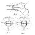
- FIG. 1illustrates a broken femur on which has been installed an implant constructed in accordance with the principles of the present invention
- FIG. 1 ais a detail view of the portion of FIG. 1 denoted by the circle A, illustrating the inventive implant in its initial state;
- FIG. 1 bis a detail view similar to FIG. 1 a , illustrating the inventive implant in its expanded state
- FIG. 2is a view showing a modified embodiment of the inventive implant.
- Such a devicecomprising a spring tensioner and a band.
- FIG. 1a broken head of a femur 10 having a fracture 12 .
- a cerclage device 14comprising a tension band, holds two bone fragments 16 , 18 , resulting from the fracture 12 , together.
- the tension band 14comprises suture or other suitable banding substance 20 and a resilient body 22 .
- the tension band 14is designed so that continuous tension is applied throughout the healing process. As bone fragments 16 , 18 heal and fuse together, these fragments actually move and absorb into one another. As is desirable for optimum healing, tension band 14 supplies the forces necessary to push the bone fragments 16 , 18 into one another.
- Optimal healingdictates that the initial forces imparted on the bone fragments 16 , 18 are not as high as the physiological or native load bearing force that one would expect at the healing site. This imposes competing functions for the tensioning device 14 at its initial state.
- the inventive device 14addresses the challenges presented by these competing functions by providing a mechanism that interferes with the resilient function of tensioning device 14 should excessive forces be realized.
- the resilient nature of the tensioning device 14diminishes as springs 24 convert their potential energy into energy directed to pulling the suture in, as bone fragments 16 , 18 move into each other. As the springs 24 lose their potential energy, the compression they are able to impart on bone fragments 16 , 18 diminishes.
- Optimal bone healingrequires that some suture tension be maintained until the end of the healing cycle. Normally a resilient mechanism decreases its rate of energy release until it approximates zero at the end of the cycle. This is not desirable according to optimal healing parameters, but is desirable to the extent that zero forces need to be realized at the end of the healing cycle in order to avoid strangulation of the tissue.
- Tensioning device 14will start to act as a tourniquet and to strangle the tissue just healed. Again, there are competing functions for the tensioning device 14 .
- the present inventionaddresses this problem by pre-loading the resilient mechanism with the amount of minimum energy needed to induce optimum healing.
- FIG. 1 aillustrates the resilient body 22 in its initial state.
- Spring elements 24 within the resilient body 22serve to pull on suture ends 26 , 28 , which are attached to attachment portions on opposed ends of the resilient body 22 as shown, thereby tensioning the suture 20 , which acts to pull the bone fragments 16 and 18 together.
- the spring elements 24may be compressing the resilient body 22 such that a first opposing surface 29 ( FIG. 1 b ) of a stop 30 is being pressed into a second opposing surface 31 ( FIG. 1 b ) of a stop 32 , on each side of the resilient body 22 .
- This initial compressioneffectively preloads the resilient body 22 to ensure that tension is applied to the suture 20 , which in turn compresses bone fragments 16 , 18 at the end of the healing cycle. But, because stops 30 , 32 come into contact with one another, via their respective opposing surfaces 29 , 31 , tissue strangulation is avoided.
- the springs 24are leaf springs, and are designed to pull with the appropriate level of tension to generate optimal compression in the fracture 12 , so that the femur will heal as quickly as possible.
- FIG. 1 billustrates the springs 24 in their full extension, storing all of the potential energy needed to perform the functions required of the tensioning device 14 .
- Loading springs 24requires the tensioning of the suture ends 26 , 28 into the tensioning device 14 , and then locking or binding suture ends 26 , 28 to the tensioning device 14 as indicated.
- a gap 34is disposed between the respective opposing surfaces 29 , 31 of the stops 30 , 32 , indicating that the resilient mechanism has been loaded with energy. Gap 34 is also the distance to be traveled during the healing process. When the gap 34 widens, each spring 24 contacts and interferes with the outwardly adjacent surfaces of its adjacent stops 30 , 32 , as shown in FIG. 1 b .
- This interference between the springs and the adjacent respective stopsconstrains further widening of the gaps 34 , by increasing, at a much higher rate, the forces necessary to further widen the gaps because of the need to overcome the interference forces.
- the present inventionenables this higher force rate to be matched with expected physiologic or native load bearing forces.
- the spatial relationships between the springs 24 and the stops 30 , 32can be arranged to predetermine the maximum effective size of the gaps 34 in accordance with the desired application.
- the tensioning device 14is ready to provide compression between bone halves 16 , 18 , while also providing greater resistance to expected physiologic or native load bearing forces and while also terminating all compressive forces once the fracture 12 has fully healed.
- One important feature of the inventionis in the aspect of the design specification that requires the tensioning device 14 to not strangulate healing bone halves 16 , 18 .
- the two components that can supply forces that result in strangulationare the spring 24 and the suture 20 . Should either of these components be made of a bio-absorbable material, that component may be designed to be absorbed before permanent strangulation is realized.
- the spring 24is the likely candidate to be made out of a permanent material because of the high demands made on it (bio-absorbable materials afford inferior resiliency performance relative to a permanent material such as stainless steel).
- the device 14is made of a hybrid of two materials, bio-absorbable suture 20 and a metal resilient body 22 .
- the cerclage device 14affords added protection against strangulation, in that its suture will absorb over time, thus limiting the ability of the device 14 to damage tissue.
- the resilient bodyis free to move. This may be a serious problem, in that loose implants can migrate into joints or organs in a manner which may damage tissue.
- the present inventionaddresses this dynamic in two different embodiments.
- the first embodimentaddresses the manner in which the suture absorbs.
- the suture 20itself is preferably a hybrid structure.
- the absorbable portion, or base, of the suture 20bears the stress or tension in the suture.
- a non-absorbable structureis woven into the absorbable base of the suture 20 in such a manner as to zig-zag across its profile. When the absorbable structure goes away, through absorption, the zig-zag structure expands to relieve strangulation, while still holding the resilient body in place so that it cannot migrate within the body.
- FIG. 2illustrates a second embodiment of the invention, as well as a second approach for addressing the dynamic noted above with respect to the usage of bio-absorbable suture.
- the embodiment of FIG. 2shows another way of addressing the fixation of the resilient body 22 once the bio-absorbable suture 20 has absorbed.
- the resilient body 22includes an eyelet 40 , which is configured to accept a screw. The screw passes through the eyelet 40 , and into the bone, thus attaching the resilient body permanently to the bone.
- the resilient bodyis always fixed to the bone, and will not migrate throughout the body when the absorbable suture is absorbed by the body, thus mitigating the need to utilise the hybrid suture 20 discussed above in conjunction with the embodiment of FIG. 1 .
- Cerclage devicesmay have bands or cables, instead of the sutures described herein. Cerclage devices may also have buckles or clamps, instead of the resilient body described herein. Additionally, any implant whose hybrid nature causes it to become unstable and to move around the body as the body absorbs the absorbable portion of the implant may benefit from the principles of the present invention.
Landscapes
- Health & Medical Sciences (AREA)
- Orthopedic Medicine & Surgery (AREA)
- Surgery (AREA)
- Life Sciences & Earth Sciences (AREA)
- Heart & Thoracic Surgery (AREA)
- Nuclear Medicine, Radiotherapy & Molecular Imaging (AREA)
- Engineering & Computer Science (AREA)
- Biomedical Technology (AREA)
- Neurology (AREA)
- Medical Informatics (AREA)
- Molecular Biology (AREA)
- Animal Behavior & Ethology (AREA)
- General Health & Medical Sciences (AREA)
- Public Health (AREA)
- Veterinary Medicine (AREA)
- Surgical Instruments (AREA)
- Prostheses (AREA)
Abstract
Description
Claims (20)
Priority Applications (1)
| Application Number | Priority Date | Filing Date | Title |
|---|---|---|---|
| US13/476,669US8974456B2 (en) | 2011-05-19 | 2012-05-21 | Hybrid medical device implant with migration management |
Applications Claiming Priority (2)
| Application Number | Priority Date | Filing Date | Title |
|---|---|---|---|
| US201161487889P | 2011-05-19 | 2011-05-19 | |
| US13/476,669US8974456B2 (en) | 2011-05-19 | 2012-05-21 | Hybrid medical device implant with migration management |
Publications (2)
| Publication Number | Publication Date |
|---|---|
| US20140018808A1 US20140018808A1 (en) | 2014-01-16 |
| US8974456B2true US8974456B2 (en) | 2015-03-10 |
Family
ID=49914613
Family Applications (1)
| Application Number | Title | Priority Date | Filing Date |
|---|---|---|---|
| US13/476,669Expired - Fee RelatedUS8974456B2 (en) | 2011-05-19 | 2012-05-21 | Hybrid medical device implant with migration management |
Country Status (1)
| Country | Link |
|---|---|
| US (1) | US8974456B2 (en) |
Cited By (18)
| Publication number | Priority date | Publication date | Assignee | Title |
|---|---|---|---|---|
| US20140277142A1 (en)* | 2013-03-14 | 2014-09-18 | Spinal Elements, Inc. | Apparatus for spinal fixation and methods of use |
| US9675387B2 (en) | 2004-02-06 | 2017-06-13 | Spinal Elements, Inc. | Vertebral facet joint prosthesis and method of fixation |
| US9743937B2 (en) | 2007-02-22 | 2017-08-29 | Spinal Elements, Inc. | Vertebral facet joint drill and method of use |
| US9808294B2 (en) | 2011-02-24 | 2017-11-07 | Spinal Elements, Inc. | Methods and apparatus for stabilizing bone |
| US9839450B2 (en) | 2013-09-27 | 2017-12-12 | Spinal Elements, Inc. | Device and method for reinforcement of a facet |
| USD810942S1 (en) | 2011-10-26 | 2018-02-20 | Spinal Elements, Inc. | Interbody bone implant |
| USD812754S1 (en) | 2013-03-14 | 2018-03-13 | Spinal Elements, Inc. | Flexible elongate member with a portion configured to receive a bone anchor |
| US9931142B2 (en) | 2004-06-10 | 2018-04-03 | Spinal Elements, Inc. | Implant and method for facet immobilization |
| US10022161B2 (en) | 2011-02-24 | 2018-07-17 | Spinal Elements, Inc. | Vertebral facet joint fusion implant and method for fusion |
| US10194955B2 (en) | 2013-09-27 | 2019-02-05 | Spinal Elements, Inc. | Method of placing an implant between bone portions |
| US10251679B2 (en) | 2013-03-14 | 2019-04-09 | Spinal Elements, Inc. | Apparatus for bone stabilization and distraction and methods of use |
| US10758361B2 (en) | 2015-01-27 | 2020-09-01 | Spinal Elements, Inc. | Facet joint implant |
| US11304733B2 (en) | 2020-02-14 | 2022-04-19 | Spinal Elements, Inc. | Bone tie methods |
| US11457959B2 (en) | 2019-05-22 | 2022-10-04 | Spinal Elements, Inc. | Bone tie and bone tie inserter |
| US11464552B2 (en) | 2019-05-22 | 2022-10-11 | Spinal Elements, Inc. | Bone tie and bone tie inserter |
| US11478275B2 (en) | 2014-09-17 | 2022-10-25 | Spinal Elements, Inc. | Flexible fastening band connector |
| US12369952B2 (en) | 2021-12-10 | 2025-07-29 | Spinal Elements, Inc. | Bone tie and portal |
| US12440242B2 (en) | 2024-04-29 | 2025-10-14 | Spinal Elements, Inc. | Flexible fastening band connector |
Families Citing this family (2)
| Publication number | Priority date | Publication date | Assignee | Title |
|---|---|---|---|---|
| WO2013040456A1 (en) | 2011-09-14 | 2013-03-21 | Band-Lok, Llc | Tether clamp and implantation system |
| EP3490474A4 (en) | 2016-07-26 | 2019-08-28 | Band-lok, LLC | ORTHOPEDIC IMPLANTS. |
Citations (50)
| Publication number | Priority date | Publication date | Assignee | Title |
|---|---|---|---|---|
| US303360A (en) | 1884-08-12 | Friedrich hermann brunner | ||
| US3822445A (en) | 1973-03-26 | 1974-07-09 | C Feng | Drawstring with clips |
| US4279248A (en) | 1979-07-20 | 1981-07-21 | Shlomo Gabbay | Sternum closure device and procedure for using same |
| US4444181A (en) | 1980-11-10 | 1984-04-24 | Queen's University At Kingston | Bone clip |
| US4535772A (en) | 1983-03-10 | 1985-08-20 | Kells Medical, Incorporated | Skin closure device |
| US4667675A (en) | 1986-03-06 | 1987-05-26 | Davis Emsley A | Retention suture apparatus |
| US4730615A (en) | 1986-03-03 | 1988-03-15 | Pfizer Hospital Products Group, Inc. | Sternum closure device |
| US4813416A (en) | 1987-03-18 | 1989-03-21 | The Research Foundation Of State University Of New York | Bonding assembly and method for sternum closing |
| US4938760A (en) | 1989-03-29 | 1990-07-03 | American Medical Systems, Inc. | Female suspension procedure |
| US5330489A (en) | 1992-10-09 | 1994-07-19 | United States Surgical Corporation | Sternum closure buckle |
| US5366461A (en) | 1993-01-25 | 1994-11-22 | William Blasnik | Sternum banding assembly |
| US5571105A (en) | 1993-07-06 | 1996-11-05 | Gundolf; Ferdinand | Osteosynthesis apparatus for the fixation of bone fragments |
| US5722976A (en) | 1993-08-27 | 1998-03-03 | Brown; Robin Peter | Apparatus and method for surgically securing bone parts |
| US5797915A (en)* | 1996-04-17 | 1998-08-25 | Pierson, Iii; Raymond H. | Cerclage system |
| US5807214A (en) | 1997-03-06 | 1998-09-15 | The Hygenic Corporation | Connector for securing an exercise member |
| US5810854A (en) | 1997-01-24 | 1998-09-22 | Beach; William R. | Method and apparatus for attaching connective tissue to each other or underlying bone |
| US5849012A (en) | 1996-03-11 | 1998-12-15 | Abboudi; Shalom Y. | Surgical clamping assemblies and methods of use |
| US5972006A (en) | 1997-01-28 | 1999-10-26 | Stony Brook Surgical Innovations, Inc. | Buckle securing means for sternum banding assembly |
| US6051007A (en) | 1998-03-02 | 2000-04-18 | Corvascular, Inc. | Sternal closure device and instruments therefor |
| US6066160A (en) | 1998-11-23 | 2000-05-23 | Quickie Llc | Passive knotless suture terminator for use in minimally invasive surgery and to facilitate standard tissue securing |
| US6080185A (en) | 1998-10-16 | 2000-06-27 | Cardiac Assist Technologies, Inc. | Stop mechanism and method therefor |
| US20020147449A1 (en) | 2001-04-09 | 2002-10-10 | David Yun | Spine fixation device and method |
| US6471715B1 (en) | 1998-01-19 | 2002-10-29 | Wisebands Ltd | Suture tightening device for closing wounds and method for its use |
| US6540769B1 (en) | 2001-10-31 | 2003-04-01 | Miller, Iii Archibald S. | Method and apparatus for closing a severed sternum |
| US6547725B1 (en) | 1998-08-10 | 2003-04-15 | Coroneo, Inc. | Surgical suture and associated anchoring mechanism for tissue retraction |
| US20030093117A1 (en) | 1999-06-25 | 2003-05-15 | Vahid Saadat | Implantable artificial partition and methods of use |
| US6589246B1 (en) | 2001-04-26 | 2003-07-08 | Poly-4 Medical, Inc. | Method of applying an active compressive force continuously across a fracture |
| US6648903B1 (en) | 1998-09-08 | 2003-11-18 | Pierson, Iii Raymond H. | Medical tensioning system |
| US20050075653A1 (en) | 1999-06-25 | 2005-04-07 | Usgi Medical Inc. | Apparatus and methods for forming and securing gastrointestinal tissue folds |
| US20050090827A1 (en) | 2003-10-28 | 2005-04-28 | Tewodros Gedebou | Comprehensive tissue attachment system |
| US20050149121A1 (en) | 2003-12-22 | 2005-07-07 | John Crombie | Suture anchoring device |
| US20050240203A1 (en) | 2002-08-06 | 2005-10-27 | University De La Mediterranee (Aix-Marseille Ii) | Semi-automatic suture device for using surgical thread |
| US20050251209A1 (en) | 2004-05-07 | 2005-11-10 | Usgi Medical Inc. | Apparatus and methods for positioning and securing anchors |
| US6969398B2 (en) | 2001-10-31 | 2005-11-29 | Leonard Stevens | Method and apparatus for closing a severed sternum |
| US6997189B2 (en) | 1998-06-05 | 2006-02-14 | Broncus Technologies, Inc. | Method for lung volume reduction |
| US7108710B2 (en) | 2002-11-26 | 2006-09-19 | Abbott Laboratories | Multi-element biased suture clip |
| US20070073289A1 (en) | 2005-09-27 | 2007-03-29 | Depuy Spine, Inc. | Posterior dynamic stabilization systems and methods |
| US20070112385A1 (en) | 2005-11-15 | 2007-05-17 | Conlon Sean P | Expandable suture anchor |
| US20070213725A1 (en) | 2006-03-10 | 2007-09-13 | Hack Bradford H | Intra-medullary implant with active compression |
| US20070276437A1 (en) | 2006-05-25 | 2007-11-29 | Mitralign, Inc. | Lockers for surgical tensioning members and methods of using the same to secure surgical tensioning members |
| US20070293864A1 (en) | 2006-06-16 | 2007-12-20 | Reimels William J | Bone plate system providing dynamic compression |
| US20070293863A1 (en) | 2006-06-16 | 2007-12-20 | Reimels William J | Bone bridge providing dynamic compression on bone fractures |
| US20080004624A1 (en) | 2006-06-30 | 2008-01-03 | Olroyd Craig D | Cable anchor for attaching elastic cable to a bony substrate |
| US7341558B2 (en) | 2003-09-19 | 2008-03-11 | Medcanica, Llc | Pericardial retractor |
| US7416556B2 (en) | 2002-06-06 | 2008-08-26 | Abbott Laboratories | Stop-cock suture clamping system |
| US20090062853A1 (en) | 2007-08-31 | 2009-03-05 | Mcmichael Donald Jay | Suture Retention Hub |
| US7722632B2 (en) | 2003-05-09 | 2010-05-25 | Medtronic, Inc. | Surgical suture holding device |
| US20100298828A1 (en)* | 2007-08-10 | 2010-11-25 | Lluis Chico Roca | fixation device for the fixation of bone fragments |
| US7867251B2 (en) | 2001-11-08 | 2011-01-11 | Smith & Nephew, Inc. | Reattachment of tissue to base tissue |
| US20120109199A1 (en)* | 2008-11-12 | 2012-05-03 | Simpirica Spine, Inc. | Modulated constraining apparatus and methods of use |
- 2012
- 2012-05-21USUS13/476,669patent/US8974456B2/ennot_activeExpired - Fee Related
Patent Citations (53)
| Publication number | Priority date | Publication date | Assignee | Title |
|---|---|---|---|---|
| US303360A (en) | 1884-08-12 | Friedrich hermann brunner | ||
| US3822445A (en) | 1973-03-26 | 1974-07-09 | C Feng | Drawstring with clips |
| US4279248A (en) | 1979-07-20 | 1981-07-21 | Shlomo Gabbay | Sternum closure device and procedure for using same |
| US4444181A (en) | 1980-11-10 | 1984-04-24 | Queen's University At Kingston | Bone clip |
| US4535772A (en) | 1983-03-10 | 1985-08-20 | Kells Medical, Incorporated | Skin closure device |
| US4730615A (en) | 1986-03-03 | 1988-03-15 | Pfizer Hospital Products Group, Inc. | Sternum closure device |
| US4667675A (en) | 1986-03-06 | 1987-05-26 | Davis Emsley A | Retention suture apparatus |
| US4813416A (en) | 1987-03-18 | 1989-03-21 | The Research Foundation Of State University Of New York | Bonding assembly and method for sternum closing |
| US4938760A (en) | 1989-03-29 | 1990-07-03 | American Medical Systems, Inc. | Female suspension procedure |
| US4969892A (en) | 1989-03-29 | 1990-11-13 | Ams, Inc. | Suturing anchoring device for use in a female suspension procedure |
| US5330489A (en) | 1992-10-09 | 1994-07-19 | United States Surgical Corporation | Sternum closure buckle |
| US5366461A (en) | 1993-01-25 | 1994-11-22 | William Blasnik | Sternum banding assembly |
| US5571105A (en) | 1993-07-06 | 1996-11-05 | Gundolf; Ferdinand | Osteosynthesis apparatus for the fixation of bone fragments |
| US5722976A (en) | 1993-08-27 | 1998-03-03 | Brown; Robin Peter | Apparatus and method for surgically securing bone parts |
| US5849012A (en) | 1996-03-11 | 1998-12-15 | Abboudi; Shalom Y. | Surgical clamping assemblies and methods of use |
| US5797915A (en)* | 1996-04-17 | 1998-08-25 | Pierson, Iii; Raymond H. | Cerclage system |
| US5810854A (en) | 1997-01-24 | 1998-09-22 | Beach; William R. | Method and apparatus for attaching connective tissue to each other or underlying bone |
| US5972006A (en) | 1997-01-28 | 1999-10-26 | Stony Brook Surgical Innovations, Inc. | Buckle securing means for sternum banding assembly |
| US5807214A (en) | 1997-03-06 | 1998-09-15 | The Hygenic Corporation | Connector for securing an exercise member |
| US6471715B1 (en) | 1998-01-19 | 2002-10-29 | Wisebands Ltd | Suture tightening device for closing wounds and method for its use |
| US6051007A (en) | 1998-03-02 | 2000-04-18 | Corvascular, Inc. | Sternal closure device and instruments therefor |
| US6997189B2 (en) | 1998-06-05 | 2006-02-14 | Broncus Technologies, Inc. | Method for lung volume reduction |
| US6547725B1 (en) | 1998-08-10 | 2003-04-15 | Coroneo, Inc. | Surgical suture and associated anchoring mechanism for tissue retraction |
| US6648903B1 (en) | 1998-09-08 | 2003-11-18 | Pierson, Iii Raymond H. | Medical tensioning system |
| US6080185A (en) | 1998-10-16 | 2000-06-27 | Cardiac Assist Technologies, Inc. | Stop mechanism and method therefor |
| US6066160A (en) | 1998-11-23 | 2000-05-23 | Quickie Llc | Passive knotless suture terminator for use in minimally invasive surgery and to facilitate standard tissue securing |
| US20030093117A1 (en) | 1999-06-25 | 2003-05-15 | Vahid Saadat | Implantable artificial partition and methods of use |
| US20050075653A1 (en) | 1999-06-25 | 2005-04-07 | Usgi Medical Inc. | Apparatus and methods for forming and securing gastrointestinal tissue folds |
| US20020147449A1 (en) | 2001-04-09 | 2002-10-10 | David Yun | Spine fixation device and method |
| US6589246B1 (en) | 2001-04-26 | 2003-07-08 | Poly-4 Medical, Inc. | Method of applying an active compressive force continuously across a fracture |
| US6540769B1 (en) | 2001-10-31 | 2003-04-01 | Miller, Iii Archibald S. | Method and apparatus for closing a severed sternum |
| US6969398B2 (en) | 2001-10-31 | 2005-11-29 | Leonard Stevens | Method and apparatus for closing a severed sternum |
| US7867251B2 (en) | 2001-11-08 | 2011-01-11 | Smith & Nephew, Inc. | Reattachment of tissue to base tissue |
| US7416556B2 (en) | 2002-06-06 | 2008-08-26 | Abbott Laboratories | Stop-cock suture clamping system |
| US20050240203A1 (en) | 2002-08-06 | 2005-10-27 | University De La Mediterranee (Aix-Marseille Ii) | Semi-automatic suture device for using surgical thread |
| US7108710B2 (en) | 2002-11-26 | 2006-09-19 | Abbott Laboratories | Multi-element biased suture clip |
| US7722632B2 (en) | 2003-05-09 | 2010-05-25 | Medtronic, Inc. | Surgical suture holding device |
| US7341558B2 (en) | 2003-09-19 | 2008-03-11 | Medcanica, Llc | Pericardial retractor |
| US20050090827A1 (en) | 2003-10-28 | 2005-04-28 | Tewodros Gedebou | Comprehensive tissue attachment system |
| US20050149121A1 (en) | 2003-12-22 | 2005-07-07 | John Crombie | Suture anchoring device |
| US20050251209A1 (en) | 2004-05-07 | 2005-11-10 | Usgi Medical Inc. | Apparatus and methods for positioning and securing anchors |
| US20070073289A1 (en) | 2005-09-27 | 2007-03-29 | Depuy Spine, Inc. | Posterior dynamic stabilization systems and methods |
| US20070112385A1 (en) | 2005-11-15 | 2007-05-17 | Conlon Sean P | Expandable suture anchor |
| US20070213725A1 (en) | 2006-03-10 | 2007-09-13 | Hack Bradford H | Intra-medullary implant with active compression |
| US20070276437A1 (en) | 2006-05-25 | 2007-11-29 | Mitralign, Inc. | Lockers for surgical tensioning members and methods of using the same to secure surgical tensioning members |
| US20070293864A1 (en) | 2006-06-16 | 2007-12-20 | Reimels William J | Bone plate system providing dynamic compression |
| US20070293863A1 (en) | 2006-06-16 | 2007-12-20 | Reimels William J | Bone bridge providing dynamic compression on bone fractures |
| US20080015589A1 (en) | 2006-06-16 | 2008-01-17 | Hack Bradford H | Bone plate with dynamic compression |
| US20080004624A1 (en) | 2006-06-30 | 2008-01-03 | Olroyd Craig D | Cable anchor for attaching elastic cable to a bony substrate |
| US20100298828A1 (en)* | 2007-08-10 | 2010-11-25 | Lluis Chico Roca | fixation device for the fixation of bone fragments |
| US20090062853A1 (en) | 2007-08-31 | 2009-03-05 | Mcmichael Donald Jay | Suture Retention Hub |
| US7867253B2 (en) | 2007-08-31 | 2011-01-11 | Kimberly-Clark Worldwide, Inc. | Suture retention hub |
| US20120109199A1 (en)* | 2008-11-12 | 2012-05-03 | Simpirica Spine, Inc. | Modulated constraining apparatus and methods of use |
Cited By (36)
| Publication number | Priority date | Publication date | Assignee | Title |
|---|---|---|---|---|
| US9675387B2 (en) | 2004-02-06 | 2017-06-13 | Spinal Elements, Inc. | Vertebral facet joint prosthesis and method of fixation |
| US10085776B2 (en) | 2004-02-06 | 2018-10-02 | Spinal Elements, Inc. | Vertebral facet joint prosthesis and method of fixation |
| US9931142B2 (en) | 2004-06-10 | 2018-04-03 | Spinal Elements, Inc. | Implant and method for facet immobilization |
| US9743937B2 (en) | 2007-02-22 | 2017-08-29 | Spinal Elements, Inc. | Vertebral facet joint drill and method of use |
| US10022161B2 (en) | 2011-02-24 | 2018-07-17 | Spinal Elements, Inc. | Vertebral facet joint fusion implant and method for fusion |
| US9808294B2 (en) | 2011-02-24 | 2017-11-07 | Spinal Elements, Inc. | Methods and apparatus for stabilizing bone |
| US12343048B2 (en) | 2011-02-24 | 2025-07-01 | Spinal Elements, Inc. | Methods and apparatus for stabilizing bone |
| US11464551B2 (en) | 2011-02-24 | 2022-10-11 | Spinal Elements, Inc. | Methods and apparatus for stabilizing bone |
| US10368921B2 (en) | 2011-02-24 | 2019-08-06 | Spinal Elements, Inc. | Methods and apparatus for stabilizing bone |
| USD884896S1 (en) | 2011-10-26 | 2020-05-19 | Spinal Elements, Inc. | Interbody bone implant |
| USD958366S1 (en) | 2011-10-26 | 2022-07-19 | Spinal Elements, Inc. | Interbody bone implant |
| USD834194S1 (en) | 2011-10-26 | 2018-11-20 | Spinal Elements, Inc. | Interbody bone implant |
| USD810942S1 (en) | 2011-10-26 | 2018-02-20 | Spinal Elements, Inc. | Interbody bone implant |
| USD857900S1 (en) | 2011-10-26 | 2019-08-27 | Spinal Elements, Inc. | Interbody bone implant |
| USD979062S1 (en) | 2011-10-26 | 2023-02-21 | Spinal Elements, Inc. | Interbody bone implant |
| USD926982S1 (en) | 2011-10-26 | 2021-08-03 | Spinal Elements, Inc. | Interbody bone implant |
| US9820784B2 (en)* | 2013-03-14 | 2017-11-21 | Spinal Elements, Inc. | Apparatus for spinal fixation and methods of use |
| US10251679B2 (en) | 2013-03-14 | 2019-04-09 | Spinal Elements, Inc. | Apparatus for bone stabilization and distraction and methods of use |
| US10426524B2 (en) | 2013-03-14 | 2019-10-01 | Spinal Elements, Inc. | Apparatus for spinal fixation and methods of use |
| US20140277142A1 (en)* | 2013-03-14 | 2014-09-18 | Spinal Elements, Inc. | Apparatus for spinal fixation and methods of use |
| USD812754S1 (en) | 2013-03-14 | 2018-03-13 | Spinal Elements, Inc. | Flexible elongate member with a portion configured to receive a bone anchor |
| US11272961B2 (en) | 2013-03-14 | 2022-03-15 | Spinal Elements, Inc. | Apparatus for bone stabilization and distraction and methods of use |
| US11517354B2 (en) | 2013-09-27 | 2022-12-06 | Spinal Elements, Inc. | Method of placing an implant between bone portions |
| US10624680B2 (en) | 2013-09-27 | 2020-04-21 | Spinal Elements, Inc. | Device and method for reinforcement of a facet |
| US10194955B2 (en) | 2013-09-27 | 2019-02-05 | Spinal Elements, Inc. | Method of placing an implant between bone portions |
| US11918258B2 (en) | 2013-09-27 | 2024-03-05 | Spinal Elements, Inc. | Device and method for reinforcement of a facet |
| US9839450B2 (en) | 2013-09-27 | 2017-12-12 | Spinal Elements, Inc. | Device and method for reinforcement of a facet |
| US11478275B2 (en) | 2014-09-17 | 2022-10-25 | Spinal Elements, Inc. | Flexible fastening band connector |
| US11998240B2 (en) | 2014-09-17 | 2024-06-04 | Spinal Elements, Inc. | Flexible fastening band connector |
| US10758361B2 (en) | 2015-01-27 | 2020-09-01 | Spinal Elements, Inc. | Facet joint implant |
| US11464552B2 (en) | 2019-05-22 | 2022-10-11 | Spinal Elements, Inc. | Bone tie and bone tie inserter |
| US11457959B2 (en) | 2019-05-22 | 2022-10-04 | Spinal Elements, Inc. | Bone tie and bone tie inserter |
| US11304733B2 (en) | 2020-02-14 | 2022-04-19 | Spinal Elements, Inc. | Bone tie methods |
| US12232778B2 (en) | 2020-02-14 | 2025-02-25 | Spinal Elements, Inc. | Bone tie methods |
| US12369952B2 (en) | 2021-12-10 | 2025-07-29 | Spinal Elements, Inc. | Bone tie and portal |
| US12440242B2 (en) | 2024-04-29 | 2025-10-14 | Spinal Elements, Inc. | Flexible fastening band connector |
Also Published As
| Publication number | Publication date |
|---|---|
| US20140018808A1 (en) | 2014-01-16 |
Similar Documents
| Publication | Publication Date | Title |
|---|---|---|
| US8974456B2 (en) | Hybrid medical device implant with migration management | |
| US8303591B1 (en) | Load shaping for dynamic tensioning mechanisms and methods | |
| JP5650541B2 (en) | Device for attaching a system that applies a load to the cruciate ligament of the knee joint | |
| US10213238B2 (en) | Method and device for correcting bone deformities | |
| US8668696B2 (en) | Low friction buckle tightening systems and methods | |
| US5540703A (en) | Knotted cable attachment apparatus formed of braided polymeric fibers | |
| US8579901B1 (en) | Suture band buckle and methods | |
| US20110060366A1 (en) | Facet Joint Implant and Related Methods | |
| US20110313435A1 (en) | Suture buckle with selective friction | |
| JP2004512898A (en) | Tension band clip | |
| US20130331848A1 (en) | Method And Apparatus For Intraosseous Membrane Reconstruction | |
| US10034663B1 (en) | Devices and methods for knotless material fixation | |
| CN105828732A (en) | Bone plate for reducing angular deformation and method of use thereof | |
| JP2013543742A (en) | Suture fixation device inserted into bone tissue | |
| US11357497B1 (en) | Surgical sheath, staple, and scaffold bone anchor devices | |
| ES3033531T3 (en) | Sternotomy closure apparatus using polymeric cable | |
| CN117958883B (en) | A joint ligament full suture repair component | |
| US8414599B1 (en) | Dynamic suture tensioning device and methods | |
| CN217310717U (en) | Degradable fixed sheath and cruciate ligament reconstruction system thereof | |
| WO2015026360A1 (en) | Hybrid medical device implant with migration management | |
| US12011154B1 (en) | Surgical bone stable device and method of use | |
| CN217186587U (en) | Fixing sheath for fixing ligament graft and cruciate ligament reconstruction system thereof | |
| US12178423B2 (en) | Dynamic tensioning devices for orthopedic compression | |
| CN109805995B (en) | Bundling and fixing device based on proximal femur intramedullary nail system | |
| WO2015026362A1 (en) | Low friction buckle tightening system and methods |
Legal Events
| Date | Code | Title | Description |
|---|---|---|---|
| AS | Assignment | Owner name:DALLEN MEDICAL, INC., CALIFORNIA Free format text:ASSIGNMENT OF ASSIGNORS INTEREST;ASSIGNORS:ALLEN, DREW;FOERSTER, SETH ARNOLD;REEL/FRAME:028486/0416 Effective date:20120628 | |
| STCF | Information on status: patent grant | Free format text:PATENTED CASE | |
| AS | Assignment | Owner name:ZIMMER, INC., INDIANA Free format text:ASSIGNMENT OF ASSIGNORS INTEREST;ASSIGNOR:DALLEN MEDICAL, INC.;REEL/FRAME:039595/0425 Effective date:20160726 | |
| FEPP | Fee payment procedure | Free format text:PAT HOLDER NO LONGER CLAIMS SMALL ENTITY STATUS, ENTITY STATUS SET TO UNDISCOUNTED (ORIGINAL EVENT CODE: STOL); ENTITY STATUS OF PATENT OWNER: LARGE ENTITY | |
| MAFP | Maintenance fee payment | Free format text:PAYMENT OF MAINTENANCE FEE, 4TH YEAR, LARGE ENTITY (ORIGINAL EVENT CODE: M1551); ENTITY STATUS OF PATENT OWNER: LARGE ENTITY Year of fee payment:4 | |
| FEPP | Fee payment procedure | Free format text:MAINTENANCE FEE REMINDER MAILED (ORIGINAL EVENT CODE: REM.); ENTITY STATUS OF PATENT OWNER: LARGE ENTITY | |
| LAPS | Lapse for failure to pay maintenance fees | Free format text:PATENT EXPIRED FOR FAILURE TO PAY MAINTENANCE FEES (ORIGINAL EVENT CODE: EXP.); ENTITY STATUS OF PATENT OWNER: LARGE ENTITY | |
| STCH | Information on status: patent discontinuation | Free format text:PATENT EXPIRED DUE TO NONPAYMENT OF MAINTENANCE FEES UNDER 37 CFR 1.362 | |
| FP | Lapsed due to failure to pay maintenance fee | Effective date:20230310 |