US8974450B2 - System and method for ablation procedure monitoring using electrodes - Google Patents
System and method for ablation procedure monitoring using electrodesDownload PDFInfo
- Publication number
- US8974450B2 US8974450B2US13/020,562US201113020562AUS8974450B2US 8974450 B2US8974450 B2US 8974450B2US 201113020562 AUS201113020562 AUS 201113020562AUS 8974450 B2US8974450 B2US 8974450B2
- Authority
- US
- United States
- Prior art keywords
- tissue
- electrodes
- antenna
- antenna assembly
- microwave
- Prior art date
- Legal status (The legal status is an assumption and is not a legal conclusion. Google has not performed a legal analysis and makes no representation as to the accuracy of the status listed.)
- Active, expires
Links
- 238000002679ablationMethods0.000titleclaimsabstractdescription36
- 238000000034methodMethods0.000titleclaimsdescription32
- 238000012544monitoring processMethods0.000titledescription5
- 238000003780insertionMethods0.000claimsabstractdescription34
- 230000037431insertionEffects0.000claimsabstractdescription34
- 230000004044responseEffects0.000claimsabstractdescription20
- 239000004020conductorSubstances0.000claimsdescription18
- 239000012212insulatorSubstances0.000claimsdescription3
- 230000000977initiatory effectEffects0.000claims1
- 230000005540biological transmissionEffects0.000description15
- 230000005670electromagnetic radiationEffects0.000description8
- 239000012530fluidSubstances0.000description8
- 230000000712assemblyEffects0.000description5
- 238000000429assemblyMethods0.000description5
- 210000004027cellAnatomy0.000description5
- 238000001514detection methodMethods0.000description5
- 239000000523sampleSubstances0.000description5
- 239000002826coolantSubstances0.000description4
- 230000006378damageEffects0.000description4
- 229910052751metalInorganic materials0.000description4
- 239000002184metalSubstances0.000description4
- 150000002739metalsChemical class0.000description4
- 238000004804windingMethods0.000description4
- 206010028980NeoplasmDiseases0.000description3
- 201000011510cancerDiseases0.000description3
- 230000005404monopoleEffects0.000description3
- 239000010935stainless steelSubstances0.000description3
- 229910001220stainless steelInorganic materials0.000description3
- RYGMFSIKBFXOCR-UHFFFAOYSA-NCopperChemical compound[Cu]RYGMFSIKBFXOCR-UHFFFAOYSA-N0.000description2
- 238000004891communicationMethods0.000description2
- 229910052802copperInorganic materials0.000description2
- 239000010949copperSubstances0.000description2
- 238000010586diagramMethods0.000description2
- 239000003989dielectric materialSubstances0.000description2
- 201000010099diseaseDiseases0.000description2
- 208000037265diseases, disorders, signs and symptomsDiseases0.000description2
- 238000002847impedance measurementMethods0.000description2
- 230000035515penetrationEffects0.000description2
- -1polytetrafluoroethylenePolymers0.000description2
- 229920001343polytetrafluoroethylenePolymers0.000description2
- 239000004810polytetrafluoroethyleneSubstances0.000description2
- 239000007787solidSubstances0.000description2
- 239000004952PolyamideSubstances0.000description1
- 229920006362Teflon®Polymers0.000description1
- ATJFFYVFTNAWJD-UHFFFAOYSA-NTinChemical compound[Sn]ATJFFYVFTNAWJD-UHFFFAOYSA-N0.000description1
- 239000000956alloySubstances0.000description1
- 229910045601alloyInorganic materials0.000description1
- 239000000919ceramicSubstances0.000description1
- 230000001112coagulating effectEffects0.000description1
- 230000015271coagulationEffects0.000description1
- 238000005345coagulationMethods0.000description1
- 239000011248coating agentSubstances0.000description1
- 238000000576coating methodMethods0.000description1
- 230000006870functionEffects0.000description1
- PCHJSUWPFVWCPO-UHFFFAOYSA-NgoldChemical compound[Au]PCHJSUWPFVWCPO-UHFFFAOYSA-N0.000description1
- 239000010931goldSubstances0.000description1
- 229910052737goldInorganic materials0.000description1
- 239000003779heat-resistant materialSubstances0.000description1
- 238000009217hyperthermia therapyMethods0.000description1
- 230000000266injurious effectEffects0.000description1
- 230000002427irreversible effectEffects0.000description1
- 239000007788liquidSubstances0.000description1
- 239000000463materialSubstances0.000description1
- 238000005259measurementMethods0.000description1
- 239000000203mixtureSubstances0.000description1
- 238000012986modificationMethods0.000description1
- 230000004048modificationEffects0.000description1
- 239000000615nonconductorSubstances0.000description1
- 239000013307optical fiberSubstances0.000description1
- 229910002077partially stabilized zirconiaInorganic materials0.000description1
- 230000000149penetrating effectEffects0.000description1
- 230000002572peristaltic effectEffects0.000description1
- 229920002647polyamidePolymers0.000description1
- 238000005476solderingMethods0.000description1
- 238000001356surgical procedureMethods0.000description1
- 239000012815thermoplastic materialSubstances0.000description1
- 229920005992thermoplastic resinPolymers0.000description1
- 229910052718tinInorganic materials0.000description1
- 239000011135tinSubstances0.000description1
- 210000004881tumor cellAnatomy0.000description1
- 210000003462veinAnatomy0.000description1
Images


Classifications
- A—HUMAN NECESSITIES
- A61—MEDICAL OR VETERINARY SCIENCE; HYGIENE
- A61B—DIAGNOSIS; SURGERY; IDENTIFICATION
- A61B18/00—Surgical instruments, devices or methods for transferring non-mechanical forms of energy to or from the body
- A61B18/18—Surgical instruments, devices or methods for transferring non-mechanical forms of energy to or from the body by applying electromagnetic radiation, e.g. microwaves
- A61B18/1815—Surgical instruments, devices or methods for transferring non-mechanical forms of energy to or from the body by applying electromagnetic radiation, e.g. microwaves using microwaves
- A—HUMAN NECESSITIES
- A61—MEDICAL OR VETERINARY SCIENCE; HYGIENE
- A61B—DIAGNOSIS; SURGERY; IDENTIFICATION
- A61B18/00—Surgical instruments, devices or methods for transferring non-mechanical forms of energy to or from the body
- A61B2018/00571—Surgical instruments, devices or methods for transferring non-mechanical forms of energy to or from the body for achieving a particular surgical effect
- A61B2018/00577—Ablation
- A—HUMAN NECESSITIES
- A61—MEDICAL OR VETERINARY SCIENCE; HYGIENE
- A61B—DIAGNOSIS; SURGERY; IDENTIFICATION
- A61B18/00—Surgical instruments, devices or methods for transferring non-mechanical forms of energy to or from the body
- A61B2018/00636—Sensing and controlling the application of energy
- A61B2018/00642—Sensing and controlling the application of energy with feedback, i.e. closed loop control
- A—HUMAN NECESSITIES
- A61—MEDICAL OR VETERINARY SCIENCE; HYGIENE
- A61B—DIAGNOSIS; SURGERY; IDENTIFICATION
- A61B18/00—Surgical instruments, devices or methods for transferring non-mechanical forms of energy to or from the body
- A61B2018/00636—Sensing and controlling the application of energy
- A61B2018/00696—Controlled or regulated parameters
- A61B2018/00702—Power or energy
- A—HUMAN NECESSITIES
- A61—MEDICAL OR VETERINARY SCIENCE; HYGIENE
- A61B—DIAGNOSIS; SURGERY; IDENTIFICATION
- A61B18/00—Surgical instruments, devices or methods for transferring non-mechanical forms of energy to or from the body
- A61B2018/00636—Sensing and controlling the application of energy
- A61B2018/00773—Sensed parameters
- A61B2018/00875—Resistance or impedance
- A—HUMAN NECESSITIES
- A61—MEDICAL OR VETERINARY SCIENCE; HYGIENE
- A61B—DIAGNOSIS; SURGERY; IDENTIFICATION
- A61B18/00—Surgical instruments, devices or methods for transferring non-mechanical forms of energy to or from the body
- A61B18/18—Surgical instruments, devices or methods for transferring non-mechanical forms of energy to or from the body by applying electromagnetic radiation, e.g. microwaves
- A61B18/1815—Surgical instruments, devices or methods for transferring non-mechanical forms of energy to or from the body by applying electromagnetic radiation, e.g. microwaves using microwaves
- A61B2018/1823—Generators therefor
- A—HUMAN NECESSITIES
- A61—MEDICAL OR VETERINARY SCIENCE; HYGIENE
- A61B—DIAGNOSIS; SURGERY; IDENTIFICATION
- A61B18/00—Surgical instruments, devices or methods for transferring non-mechanical forms of energy to or from the body
- A61B18/18—Surgical instruments, devices or methods for transferring non-mechanical forms of energy to or from the body by applying electromagnetic radiation, e.g. microwaves
- A61B18/1815—Surgical instruments, devices or methods for transferring non-mechanical forms of energy to or from the body by applying electromagnetic radiation, e.g. microwaves using microwaves
- A61B2018/183—Surgical instruments, devices or methods for transferring non-mechanical forms of energy to or from the body by applying electromagnetic radiation, e.g. microwaves using microwaves characterised by the type of antenna
- A61B2018/1838—Dipole antennas
- A—HUMAN NECESSITIES
- A61—MEDICAL OR VETERINARY SCIENCE; HYGIENE
- A61B—DIAGNOSIS; SURGERY; IDENTIFICATION
- A61B18/00—Surgical instruments, devices or methods for transferring non-mechanical forms of energy to or from the body
- A61B18/18—Surgical instruments, devices or methods for transferring non-mechanical forms of energy to or from the body by applying electromagnetic radiation, e.g. microwaves
- A61B18/1815—Surgical instruments, devices or methods for transferring non-mechanical forms of energy to or from the body by applying electromagnetic radiation, e.g. microwaves using microwaves
- A61B2018/1869—Surgical instruments, devices or methods for transferring non-mechanical forms of energy to or from the body by applying electromagnetic radiation, e.g. microwaves using microwaves with an instrument interstitially inserted into the body, e.g. needles
- A61B2019/462—
- A—HUMAN NECESSITIES
- A61—MEDICAL OR VETERINARY SCIENCE; HYGIENE
- A61B—DIAGNOSIS; SURGERY; IDENTIFICATION
- A61B90/00—Instruments, implements or accessories specially adapted for surgery or diagnosis and not covered by any of the groups A61B1/00 - A61B50/00, e.g. for luxation treatment or for protecting wound edges
- A61B90/06—Measuring instruments not otherwise provided for
- A61B2090/062—Measuring instruments not otherwise provided for penetration depth
Definitions
- the present disclosurerelates to apparatus and methods for providing energy to tissue and, more particularly, to electromagnetic radiation delivery procedures utilizing ablation probes and methods of monitoring an ablation procedure using electrodes.
- Electromagnetic radiationcan be used to heat and destroy tumor cells. Treatment may involve inserting ablation probes into tissues where cancerous tumors have been identified. Once the probes are positioned, electromagnetic energy is passed through the probes into surrounding tissue.
- Electrosurgical devices utilizing electromagnetic radiationhave been developed for a variety of uses and applications. A number of devices are available that can be used to provide high bursts of energy for short periods of time to achieve cutting and coagulative effects on various tissues. There are a number of different types of instruments that can be used to perform ablation procedures.
- microwave instruments for use in ablation proceduresinclude a microwave generator, which functions as an energy source, and a microwave surgical instrument having an antenna assembly for directing the energy to the target tissue.
- the microwave generator and surgical instrumentare typically operatively coupled by a cable assembly having a plurality of conductors for transmitting microwave energy from the generator to the instrument, and for communicating control, feedback and identification signals between the instrument and the generator.
- Microwave energyis typically applied via antenna assemblies that can penetrate tissue.
- antenna assembliessuch as monopole and dipole antenna assemblies.
- microwave energygenerally radiates perpendicularly away from the axis of the conductor.
- a monopole antenna assemblyincludes a single, elongated conductor that transmits microwave energy.
- a typical dipole antenna assemblyhas two elongated conductors, which are linearly aligned and positioned end-to-end relative to one another with an electrical insulator placed therebetween. Each conductor may be about 1 ⁇ 4 of the length of a wavelength of the microwave energy, making the aggregate length of the two conductors about 1 ⁇ 2 of the wavelength of the supplied microwave energy.
- microwave antenna assembliesradiate microwave fields that, when the antenna assembly is used properly, are used therapeutically.
- the radiated microwave fieldsmay pose a hazard to both the patient and the user of the antenna assembly.
- Improper use of an antenna assemblymay include insufficient insertion depth of the shaft of the antenna assembly into tissue.
- microwave fieldsmay undesirably propagate along the shaft toward the user.
- a microwave ablation systemincludes an antenna assembly configured to deliver microwave energy from a power source to tissue.
- One or more electrodesare disposed on the antenna assembly and are configured to be positioned relative to tissue upon insertion of the antenna assembly into tissue.
- the one or more electrodesare configured to generate a feedback signal in response to an electrical signal supplied thereto from the power source.
- the feedback signalcorresponds to the proximity of tissue relative to the at least one electrode and is configured to be compared to a predetermined parameter to determine a depth of the insertion of the antenna assembly into tissue.
- the power sourceis configured to control the delivery of microwave energy to the antenna assembly based on the comparison.
- a method of performing a tissue ablation procedureincludes the steps of inserting an antenna assembly into tissue and generating an electrical signal from a power source to at least one electrode disposed on the antenna assembly.
- the methodalso includes the step of generating a feedback signal in response to the electrical signal.
- the feedback signaldepends on the proximity of tissue relative to the at least one electrode.
- the methodalso includes the steps of comparing the feedback signal to a predetermined parameter and determining an insertion depth of the antenna assembly relative to tissue based on the comparison.
- the methodalso includes the step of controlling delivery of energy from the power source to the antenna assembly for application to tissue based on the comparison.
- a microwave antenna assemblyincludes an antenna configured to deliver microwave energy to tissue.
- the antennaincludes an inner conductor, an outer conductor and an inner insulator disposed therebetween.
- One or more electrodesare disposed on the antenna and are configured to be positioned relative to tissue upon insertion of the antenna into tissue.
- the one or more electrodesare configured to receive an electrical signal and generate a feedback signal in response to the received signal.
- the feedback signalcorresponds to the proximity of tissue relative to the at least one electrode and the feedback signal is configured to be compared to one or more predetermined parameters to determine a depth of the insertion of the antenna into tissue.
- the delivery of microwave energy from the antenna to tissueis based on the comparison.
- FIG. 1shows a diagram of a microwave antenna assembly in accordance with an embodiment of the present disclosure
- FIG. 2Ashows a perspective view of a distal end of the microwave antenna assembly of FIG. 1 ;
- FIG. 2Bshows a side view of a distal end of the microwave antenna assembly of FIG. 1 ;
- FIG. 3shows a system block diagram of a microwave antenna assembly according to another embodiment of the present disclosure
- FIG. 4Ashows a distal end of the microwave antenna assembly of FIG. 3 according to another embodiment of the present disclosure
- FIG. 4Bshows a pair of electrodes separated from the microwave antenna assembly of FIG. 4A ;
- FIG. 5Ashows a distal end of the microwave antenna assembly of FIG. 3 according to another embodiment of the present disclosure
- FIG. 5Bshows a pair of electrodes separated from the microwave antenna assembly of FIG. 5A ;
- FIG. 6Ashows a distal end of the microwave antenna assembly of FIG. 3 according to another embodiment of the present disclosure
- FIG. 6Bshows a pair of electrodes separated from the microwave antenna assembly of FIG. 6A ;
- FIG. 7Ashows a distal end of the microwave antenna assembly of FIG. 3 according to another embodiment of the present disclosure
- FIG. 7Bshows an electrode separated from the microwave antenna assembly of FIG. 7A ;
- FIG. 8Ashows a distal end of the microwave antenna assembly of FIG. 3 according to another embodiment of the present disclosure
- FIG. 8Bshows a pair of electrodes separated from the microwave antenna assembly of FIG. 8A ;
- FIG. 9shows a distal end of the microwave antenna assembly of FIG. 3 according to another embodiment of the present disclosure.
- proximalwill refer to the portion of a structure that is closer to a user
- distalwill refer to the portion of the structure that is farther from the user.
- the present disclosureis directed to a microwave antenna assembly having an energy source or generator adapted to deliver energy to tissue via the antenna assembly. More particularly, the present disclosure is directed to monitoring insertion depth of the microwave antenna assembly into tissue and controlling the delivery of energy from the energy source based on the monitored insertion depth.
- two or more bipolar electrodesare operably coupled to the antenna assembly and an associated energy source.
- the energy sourcesupplies electrical energy (e.g., RF energy) to each bipolar electrode in a bipolar manner to elicit a measurable response (e.g., impedance, capacitance, inductance, etc.) that varies depending on whether tissue is present at or between the bipolar electrodes.
- the bipolar electrodesmay be strategically disposed on the antenna assembly at a predetermined location such that as the antenna assembly travels distally into tissue and, likewise, as tissue travels proximally along the longitudinal length of the antenna assembly to reach the proximity of the bipolar electrodes, the elicited response at the bipolar electrodes detectably changes relative to when tissue is absent from the proximity of the bipolar electrodes.
- the difference in the elicited response between the presence and non-presence of tissue at or between the bipolar electrodesis detected by the energy source and interpreted in accordance with predetermined data (e.g., a range of impedance values, capacitance values, and/or inductance values) to determine whether the insertion depth of the antenna assembly is adequate or inadequate.
- predetermined datae.g., a range of impedance values, capacitance values, and/or inductance values
- one or more monopolar electrodesmay be operably coupled to the antenna assembly and an associated energy source.
- the energy sourcesupplies electrical energy (e.g., RF energy) to the monopolar electrode(s) in a monopolar manner to elicit a measurable response (e.g., impedance, capacitance, inductance, etc.) that varies depending on whether tissue is present at the monopolar electrode(s).
- microwavegenerally refers to electromagnetic waves in the frequency range of 300 megahertz (MHz) (3 ⁇ 108 cycles/second) to 300 gigahertz (GHz) (3 ⁇ 1011 cycles/second).
- transmission linegenerally refers to any transmission medium that can be used for the propagation of signals from one point to another.
- Electrosurgical systems for treating tissuemay be implemented using electromagnetic radiation at microwave frequencies or at other frequencies.
- Electrosurgical systems for treating tissuedeliver microwave power to a plurality of electrosurgical devices.
- Electrosurgical devices, such as ablation probes, for implementing embodiments of the present disclosuremay be inserted directly into tissue, inserted through a lumen, such as a vein, needle or catheter, placed into the body during surgery by a clinician, or positioned in the body by other suitable methods.
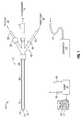
- FIG. 1shows a microwave ablation system 10 that includes a microwave antenna assembly 12 coupled to a microwave generator 14 via a flexible coaxial cable 16 .
- the generator 14is configured to provide microwave energy at an operational frequency from about 300 MHz to about 10,000 MHz, although other suitable frequencies are also contemplated.
- the antenna assembly 12includes a radiating portion 18 connected by feedline 20 (or shaft) to the cable 16 . More specifically, the antenna assembly 12 is coupled to the cable 16 through a connection hub 22 having an outlet fluid port 30 and an inlet fluid port 32 that are connected in fluid communication with a sheath 38 .
- the sheath 38encloses radiating portion 18 and feedline 20 to form a chamber 89 ( FIG. 2 ) allowing a coolant fluid 37 to circulate from port 32 around the antenna assembly 12 to port 30 .
- the ports 30 and 32are also coupled to a supply pump 34 via supply lines 88 and 86 , respectively.
- Supply pump 34is, in turn, fluidly coupled to a supply tank 36 .
- the supply pump 34may be a peristaltic pump or any other suitable type.
- the supply tank 36stores the coolant fluid 37 and, in some embodiments, may maintain the fluid at a predetermined temperature. More specifically, the supply tank 36 may include a coolant unit that cools the returning liquid from the antenna assembly 12 . In another embodiment, the coolant fluid 37 may be a gas and/or a mixture of fluid and gas.
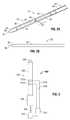
- FIGS. 2A and 2Billustrate the radiating portion 18 of the antenna assembly 12 having a dipole antenna 40 .
- the dipole antenna 40is coupled to the feedline 20 that electrically connects antenna assembly 12 to the generator 14 .
- the feedline 20includes an inner conductor 50 (e.g., wire) surrounded by an insulator 52 that is, in turn, surrounded by an outer conductor 56 (e.g., a cylindrical conducting sheath).
- the inner and outer conductorsmay be constructed of copper, gold, stainless steel, or other conductive metals with similar conductivity properties.
- the metalsmay be plated with other materials, for example, other conductive materials.
- feedline 20may be formed from a coaxial semi-rigid or flexible cable.
- the dipole antenna 40includes a proximal portion 42 and a distal portion 44 interconnected at a feed point 46 .
- the distal portion 44 and the proximal portion 42may be either balanced (e.g., of equal lengths) or unbalanced (e.g., of unequal lengths).
- a dipole feed gap “G”is disposed between the proximal and distal portions 42 and 44 at the feed point 46 .
- the gap “G”may be from about 1 mm to about 3 mm.
- the gap “G”may be thereafter filled with a dielectric material at the feed point 46 .
- the dielectric materialmay be polytetrafluoroethylene (PTFE), such as Teflon® sold by DuPont of Willmington, Del.
- the gap “G”may be coated with a dielectric seal coating.
- the distal portion 44includes a conductive member 45 that may be formed from any type of conductive material, such as metals (e.g., copper, stainless steel, tin, and various alloys thereof).
- the distal portion 44may have a solid structure and may be formed from solid wire (e.g., 10 AWG).
- the antenna assembly 12also includes a choke 60 disposed around the feedline 20 .
- the choke 60may be a quarter-wavelength shorted choke that is shorted to the feedline 20 at the proximal end (not illustrated) of the choke 60 by soldering or other suitable methods.
- antenna assembly 12also includes a tip 48 having a tapered end 24 that terminates, in one embodiment, at a pointed end 26 to allow for insertion into tissue with minimal resistance at a distal end of the radiating portion 18 .
- tip 48may be rounded or flat.
- the tip 48may be formed from a variety of heat-resistant materials suitable for penetrating tissue, such as metals (e.g., stainless steel), various thermoplastic materials (e.g., poletherimide and polyamide thermoplastic resins), and ceramics (e.g., partially stabilized zirconia).
- a microwave ablation systemshown generally as 200 , according to an embodiment of the present disclosure is depicted.
- the system 200includes an ablation device 202 having a handle 205 and an antenna 203 used to ablate tissue.
- a microwave generator 206which is substantially similar to generator 14 of FIG. 1 , supplies the ablation device 202 with energy (e.g., microwave energy) via coaxial cable 204 .
- a pair of electrodes 212 a and 212 bare disposed on the antenna 203 and operably coupled to a controller 216 via transmission lines 214 a and 214 b , respectively.
- Controller 216may be operably coupled to the microwave generator 206 , as illustrated in FIG. 3 , or may be incorporated within the microwave generator 206 (not shown).
- transmission lines 214 a and 214 bmay extend proximally from electrodes 212 a and 212 b along an outer surface of the antenna 203 (e.g., via conductive tracing), and, further, through the handle 205 and cable 204 for connection to the generator 206 and/or controller 216 .
- Electrodes 212 a and 212 bare electrically connected to the generator 206 such that generator 206 supplies electrosurgical energy (e.g., RF energy, microwave energy, etc.) to electrodes 212 a and 212 b in a bipolar configuration. More specifically, generator 206 generates energy at a first potential (e.g., “ ⁇ ”) to one of the electrodes (e.g., 212 a ) and at a second potential (e.g., “+”) to the other electrode (e.g., 212 b ).
- a first potentiale.g., “ ⁇ ”
- a second potentiale.g., “+”
- electrodes 212 a , 212 bare configured to conduct a suitable amount of electrosurgical energy therethrough such that a measurable response (e.g., impedance, capacitance, inductance, etc.) may be elicited from electrodes 212 a , 212 b caused by the proximity or lack of presence or lack of presence of tissue relative to the electrodes 212 a , 212 b . As described in more detail below, this measurable response varies depending on the proximity of tissue to the electrodes 212 a , 212 b .
- a measurable responsee.g., impedance, capacitance, inductance, etc.
- the measurable response corresponding to the presence of tissue at or between the electrodes 212 a , 212 bis detectably different from the measurable response corresponding to the lack of presence of tissue at or between the electrodes 212 a , 212 b . It is this variation in the measurable response that is monitored by the controller 216 and/or generator 206 to determine whether the insertion depth of the antenna 203 relative to tissue is desired or appropriate. This determination is, in turn, utilized to control the delivery of energy from the generator 206 to the antenna 203 .
- controller 216is configured to control the output of generator 206 based on an input signal received from one of or both of electrodes 212 a and 212 b in response to an electrical signal (e.g., RF energy) transmitted from generator 206 to electrodes 212 a , 212 b via transmission lines 214 a , 214 b , respectively.
- an electrical signale.g., RF energy
- Controller 216may be a microprocessor or any suitable logic circuit configured to receive and process an input signal from electrodes 212 a and 212 b and control output of generator 206 based on the processed input signal. Controller 216 may be operably coupled to a storage device or memory (not shown) configured to store programmable instructions, historical data, lookup tables, operating parameters, etc.
- impedance measurements of electrodes 212 a and 212 bmay be utilized to monitor the insertion depth of antenna 203 relative to tissue.
- the impedance of electrodes 212 a and 212 b when no tissue is present at or between electrodes 212 a and 212 bis detectably different than the impedance of electrodes 212 a and 212 b when tissue is present at or between electrodes 212 a and 212 b (e.g., antenna 203 is inserted into tissue at a depth sufficient to cause tissue to be disposed at or between electrodes 212 a , 212 b ).
- the detected impedance of electrodes 212 a and 212 bmay be processed by the controller 216 to detect sufficient insertion depth of antenna 203 relative to tissue and, in turn, control output of generator 206 accordingly.
- controller 216may prevent generator 206 from supplying energy to the ablation device 202 until the antenna 203 is inserted into tissue at a sufficient depth for proper operation of device 202 .
- one or more sensorsmay be in operative communication with electrodes 212 a , 212 b and configured to provide real-time information pertaining to electrodes 212 a , 212 b to the generator 206 and/or the controller 216 via suitable transmission lines. More particularly, these sensors may be configured to provide real-time information pertaining to one or more electrical parameters (e.g., impedance, power, voltage, current, etc.), thermal parameters (e.g., temperature), etc., associated with the electrodes 212 a , 212 b . In some embodiments, the sensors may be in the form of a thermal sensor such as, for example, a thermocouple, a thermistor, an optical fiber, etc.
- a thermal sensorsuch as, for example, a thermocouple, a thermistor, an optical fiber, etc.
- the sufficient insertion depth and/or the placement of electrodes 212 a and 212 b on the antenna 203may be pre-measured and/or predetermined based on any suitable parameter such as, for example without limitation, electrode geometry, electrode spacing, antenna geometry, antenna length, a manufacturer suggested minimum insertion depth, and/or a predetermined range of sufficient insertion depths.
- electrodes 212 a , 212 bmay be configured in any number of geometries and/or lateral spacing configurations in accordance with the type of elicited response being detected to determine insertion depth.
- impedance measurementssuch as resistance and capacitance may predetermine the lateral or circumferential spacing between electrodes 212 a , 212 b as well as the geometry thereof for purposes of improving the resolution between elicited responses corresponding to the presence and lack of presence of tissue, thereby optimizing the detection of insertion depth and the overall operation of system 200 .
- an electrical signal(e.g., RE energy) is generated by generator 206 and transmitted to electrodes 212 a and 212 b .
- electrodes 212 a , 212 bprovide an electrical feedback signal to the controller 216 that represents a real-time measurement or indication of one or more parameters pertaining to electrodes 212 a , 212 b such as impedance (e.g., capacitance, resistance, etc.).
- Controller 216compares the electrical signal to a predetermined range. If the electrical signal is within the predetermined range, for example, indicating that antenna 203 is inserted into tissue at an appropriate depth, the controller 216 controls the generator 206 to supply energy to the antenna 203 for application to tissue.
- the appropriate insertion depth of antenna 203may be determined prior to an ablation procedure being performed such that the supply of energy to device 202 may be initiated and/or in real-time during an ablation procedure such that the application of energy to tissue may be continued. If the electrical signal is outside the predetermined range, for example, indicating that the antenna 203 is not inserted into tissue at an appropriate depth, the controller 216 controls the generator 206 to modify or terminate generator 206 output. That is, if prior to the ablation procedure being performed it is determined that antenna 203 is not inserted into tissue at an appropriate depth, controller 216 controls generator 206 to prevent the supply of energy to device 202 .
- controller 216controls generator 206 to terminate the supply of energy to device 202 .
- generator 206will supply energy to antenna 203 for application to tissue only when antenna 203 is inserted into tissue at an appropriate depth as determined by the methods described hereinabove.
- the predetermined rangemay be, for example, a predetermined range of impedance values.
- Each of electrodes 212 a and 212 bmay be disposed anywhere along the longitudinal length of antenna 203 , e.g., proximal to the radiating portion 18 ( FIG. 1 ), and may be laterally spaced at a suitable distance from each other such that system 200 is optimized for detecting insertion depth of the antenna 203 .
- electrodes 212 a , 212 bmay be configured in any number of geometries and/or lateral spacing configurations in accordance with the type of parameter being detected to determine insertion depth.
- FIGS. 4A-8illustrate various embodiments of the ablation device 202 including bipolar electrodes that operate in conjunction with system 200 substantially as described above with respect to electrodes 212 a , 212 b to enable the detection of insertion depth of antenna 203 , and are described in detail below.
- Electrodes 312 a and 312 bare configured to operate in conjunction with microwave ablation system 200 as substantially described above with reference to electrodes 212 a and 212 b . Electrodes 312 a and 312 b are electrically connected to generator 206 and/or controller 216 ( FIG. 3 ) via transmission lines 314 a and 314 b , respectively, and include a lateral space 316 disposed therebetween.
- FIG. 3is shown operably coupled to the antenna 203 in accordance with some embodiments of the present disclosure.
- Electrodes 312 a and 312 bare configured to operate in conjunction with microwave ablation system 200 as substantially described above with reference to electrodes 212 a and 212 b . Electrodes 312 a and 312 b are electrically connected to generator 206 and/or controller 216 ( FIG. 3 ) via transmission lines 314 a and 314 b , respectively, and include a lateral space 316 disposed therebetween.
- FIG. 3is shown operably coupled to the antenna 203 in accord
- FIG. 4Bshows the pair of electrodes 312 a , 312 b separated from antenna 203 to illustrate that electrode 312 a is generally c-shaped.
- electrode 312 awhen electrode 312 a is operably coupled to antenna 203 , electrode 312 a does not completely encompass the circumference of antenna 203 such that transmission line 314 b is enabled to extend proximally along an outer surface of antenna 203 without interference from electrode 312 a , as illustrated in FIG. 4A .
- the impedance of electrodes 312 a and 312 bdetectably changes from when there is air and/or no tissue disposed within the space 316 .
- Electrodes 412 a and 412 bare configured to operate in conjunction with microwave ablation system 200 as substantially described above with reference to electrodes 212 a and 212 b . Electrodes 412 a and 412 b are electrically connected to generator 206 and/or controller 216 ( FIG. 3 ) via transmission lines 414 a and 414 b , respectively.
- FIG. 5Bshows the pair of electrodes 412 a and 412 b separated from antenna 203 to illustrate that electrodes 412 a , 412 b are generally c-shaped or half-cylinder in shape.
- electrodes 412 a , 412 bwhen electrodes 412 a , 412 b are operably coupled to antenna 203 , electrodes 412 a , 412 b do not completely encompass the circumference of antenna 203 such that a space 416 is defined therebetween.
- the impedance of electrodes 412 a , 412 bdelectably changes from when there is air and/or no tissue disposed within the space 416 .
- Electrodes 512 a and 512 bare configured to operate in conjunction with microwave ablation system 200 as substantially described above with reference to electrodes 212 a and 212 b . Electrodes 512 a and 512 h are electrically connected to generator 206 and/or controller 216 ( FIG. 3 ) via transmission lines 414 a and 414 b , respectively.
- FIG. 6Bshows the pair of electrodes 512 a , 512 b separated from antenna 203 to illustrate that electrodes 512 a , 512 b are generally c-shaped.
- Electrodes 512 a and 512 binclude a plurality of laterally spaced interlocking fingers 515 a and 515 b , respectively, that define a spacing 516 between electrodes 512 a , 512 b .
- this interlocking or nested configurationoperates to increase capacitance between electrodes 512 a , 512 b due to the close proximity of the fingers 515 a and 515 h .
- the resolution between elicited responses—namely, capacitance in the present scenario—corresponding to the presence and lack of presence of tissue within spacing 516is improved, thereby optimizing the detection of insertion depth and the overall operation of system 200 .
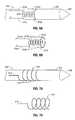
- Electrode 612is shown operably coupled to antenna 203 in accordance with some embodiments of the present disclosure.
- Electrode 612is configured to operate in conjunction with microwave ablation system 200 .
- Electrode 612is electrically connected to generator 206 and/or controller 216 ( FIG. 3 ) via a transmission line 614 .
- Generator 206generates energy at a single potential (e.g., either “+” or “ ⁇ ”) to electrode 612 .
- a return electrode or return pad attached to the patientmay be utilized to return the energy to the generator 206 , thereby completing the circuit following from the generator 206 to the antenna 203 for application to tissue and, subsequently, back to the generator 206 .
- FIG. 7Bshows the electrode 612 separated from antenna 203 to illustrate that electrode 612 is generally helical in shape such that the electrode 612 completely encircles the circumference of antenna 203 along at least a portion of the antenna's 203 longitudinal length.
- the windings of the electrode 612define lateral spacing 616 therebetween along at least a portion of the longitudinal length of the antenna 203 .
- the helical configuration of electrode 612operates to increase the electrode's 612 capacitance due to the close proximity of the helical windings thereof. In this way, the resolution between elicited responses—namely, capacitance in the present scenario—corresponding to the presence and lack of presence of tissue within spacing 616 is improved, thereby optimizing the detection of insertion depth and the overall operation of system 200 .
- Electrodes 712 a , 712 bare configured to operate in conjunction with microwave ablation system 200 . Electrodes 712 a , 712 b are electrically connected to generator 206 and/or controller 216 ( FIG. 3 ) via transmission lines 714 a , 714 b , respectively.
- Generator 206generates energy at a first potential (e.g., “+”) to electrode 712 a and at a second potential (e.g., “ ⁇ ”) to electrode 712 b .
- FIG. 8Bshows the pair of electrodes 712 a , 712 b separated from antenna 203 to illustrate that electrodes 712 a , 712 b are generally helical in shape.
- the generally helical-shaped electrodes 712 a , 712 bcompletely encircle the circumference of antenna 203 along at least a portion of the antenna's 203 longitudinal length such that the windings of electrodes 712 a , 712 b are intertwined to define lateral spacing 716 therebetween.
- the helical configuration of electrodes 712 a , 712 boperates to increase the capacitance of electrodes 712 a , 712 b due to the close proximity of the intertwined helical windings thereof. In this way, the resolution between elicited responses—namely, capacitance in the present scenario—corresponding to the presence and lack of presence of tissue within spacing 716 is improved, thereby optimizing the detection of insertion depth and the overall operation of system 200 .
- the antenna 203may be operably associated with a trocar 245 that is configured to facilitate penetration into tissue for proper placement of the antenna 203 relative to a desired tissue site.
- the trocar 245includes a hollow coaxial shaft 250 having a distal tip 258 disposed at a distal end thereof.
- the distal tip 258has a generally tapered shape, e.g., conical, to facilitate the penetration thereof, and trocar 245 generally, into tissue.
- the antenna 203is configured to be accommodated within the hollow coaxial shaft 250 such that a distal end of the antenna 203 is operably coupled to the distal tip 258 of the trocar 245 .
- the monitoring of insertion depth of antenna 203 into tissuemay be accomplished by incorporating a pair of laterally spaced electrodes 712 a and 712 b disposed along the longitudinal length of the shaft 250 . More specifically, and as shown by the illustrated embodiment of FIG. 9 , electrode 712 b forms the distal tip 258 of the trocar 245 and is electrically connected to generator 206 and/or controller 216 ( FIG. 3 ) via the inner conductor 50 (also see FIG. 2B ) of the antenna 203 .
- Electrode 712 ais ring-like in shape and encircles the circumference of the shaft 250 of trocar 245 along at least a portion of the longitudinal length of the shaft 250 . Electrode 712 a is laterally spaced proximally from electrode 712 b to define a space 716 therebetween. Electrode 712 a is electrically connected to generator 206 and/or controller 216 ( FIG. 3 ) via a transmission line 714 a . As shown in the illustrated embodiment, transmission line 714 a extends proximally from electrode 712 a along an outer surface of the trocar 245 . In some embodiments, although not shown, transmission line 714 a may be connected through the shaft 250 to the outer conductor 56 (also see FIG. 2B ) of the antenna 203 . In this scenario, the outer conductor 56 would operate to electrically connect electrode 712 a to the generator 206 and/or controller 216 ( FIG. 3 ).
Landscapes
- Health & Medical Sciences (AREA)
- Surgery (AREA)
- Life Sciences & Earth Sciences (AREA)
- Biomedical Technology (AREA)
- Medical Informatics (AREA)
- Nuclear Medicine, Radiotherapy & Molecular Imaging (AREA)
- Electromagnetism (AREA)
- Engineering & Computer Science (AREA)
- Physics & Mathematics (AREA)
- Heart & Thoracic Surgery (AREA)
- Otolaryngology (AREA)
- Molecular Biology (AREA)
- Animal Behavior & Ethology (AREA)
- General Health & Medical Sciences (AREA)
- Public Health (AREA)
- Veterinary Medicine (AREA)
- Surgical Instruments (AREA)
Abstract
Description
Claims (13)
Priority Applications (6)
| Application Number | Priority Date | Filing Date | Title |
|---|---|---|---|
| US13/020,562US8974450B2 (en) | 2011-02-03 | 2011-02-03 | System and method for ablation procedure monitoring using electrodes |
| EP16157339.9AEP3056160B1 (en) | 2011-02-03 | 2012-01-19 | Ablation device |
| EP12000334.8AEP2484303B1 (en) | 2011-02-03 | 2012-01-19 | System for monitoring ablation using bipolar electrodes |
| EP14154297.7AEP2735277B1 (en) | 2011-02-03 | 2012-01-19 | System for monitoring ablation using bipolar electrodes |
| JP2012010935AJP6376718B2 (en) | 2011-02-03 | 2012-01-23 | System and method for monitoring cauterization using electrodes |
| US14/604,368US9814525B2 (en) | 2011-02-03 | 2015-01-23 | System and method for ablation procedure monitoring using electrodes |
Applications Claiming Priority (1)
| Application Number | Priority Date | Filing Date | Title |
|---|---|---|---|
| US13/020,562US8974450B2 (en) | 2011-02-03 | 2011-02-03 | System and method for ablation procedure monitoring using electrodes |
Related Child Applications (1)
| Application Number | Title | Priority Date | Filing Date |
|---|---|---|---|
| US14/604,368ContinuationUS9814525B2 (en) | 2011-02-03 | 2015-01-23 | System and method for ablation procedure monitoring using electrodes |
Publications (2)
| Publication Number | Publication Date |
|---|---|
| US20120203217A1 US20120203217A1 (en) | 2012-08-09 |
| US8974450B2true US8974450B2 (en) | 2015-03-10 |
Family
ID=45531746
Family Applications (2)
| Application Number | Title | Priority Date | Filing Date |
|---|---|---|---|
| US13/020,562Active2034-01-10US8974450B2 (en) | 2011-02-03 | 2011-02-03 | System and method for ablation procedure monitoring using electrodes |
| US14/604,368Active2031-08-16US9814525B2 (en) | 2011-02-03 | 2015-01-23 | System and method for ablation procedure monitoring using electrodes |
Family Applications After (1)
| Application Number | Title | Priority Date | Filing Date |
|---|---|---|---|
| US14/604,368Active2031-08-16US9814525B2 (en) | 2011-02-03 | 2015-01-23 | System and method for ablation procedure monitoring using electrodes |
Country Status (3)
| Country | Link |
|---|---|
| US (2) | US8974450B2 (en) |
| EP (3) | EP2484303B1 (en) |
| JP (1) | JP6376718B2 (en) |
Cited By (11)
| Publication number | Priority date | Publication date | Assignee | Title |
|---|---|---|---|---|
| US20170202611A1 (en)* | 2014-05-28 | 2017-07-20 | Taewoong Medical Co., Ltd. | Device and method for detecting position of electrode inserted into human body |
| US9814525B2 (en) | 2011-02-03 | 2017-11-14 | Covidien Lp | System and method for ablation procedure monitoring using electrodes |
| US10271902B2 (en) | 2012-01-06 | 2019-04-30 | Covidien Lp | System and method for treating tissue using an expandable antenna |
| US10405918B2 (en) | 2012-04-30 | 2019-09-10 | Covidien Lp | Limited reuse ablation needles and ablation devices for use therewith |
| US20200261152A1 (en)* | 2016-04-28 | 2020-08-20 | Biosense Webster (Israel) Ltd. | Irrigated balloon catheter with flexible circuit electrode assembly |
| US10869674B2 (en) | 2011-07-15 | 2020-12-22 | Covidien Lp | Clip-over disposable assembly for use with hemostat-style surgical instrument and methods of manufacturing same |
| US11147622B2 (en) | 2011-03-09 | 2021-10-19 | Covidien Lp | Systems for thermal-feedback-controlled rate of fluid flow to fluid-cooled antenna assembly and methods of directing energy to tissue using same |
| US12102781B2 (en) | 2018-06-29 | 2024-10-01 | Biosense Webster (Israel) Ltd. | Reinforcement for irrigated electrophysiology balloon catheter with flexible-circuit electrodes |
| US12114905B2 (en) | 2021-08-27 | 2024-10-15 | Biosense Webster (Israel) Ltd. | Reinforcement and stress relief for an irrigated electrophysiology balloon catheter with flexible-circuit electrodes |
| US12178504B2 (en)* | 2015-07-06 | 2024-12-31 | Hermes Innovations, LLC | Surgical system and method of use |
| US12185978B2 (en) | 2015-07-06 | 2025-01-07 | Hermes Innovations, LLC | Surgical system and method of use |
Families Citing this family (18)
| Publication number | Priority date | Publication date | Assignee | Title |
|---|---|---|---|---|
| US20110257723A1 (en) | 2006-11-07 | 2011-10-20 | Dc Devices, Inc. | Devices and methods for coronary sinus pressure relief |
| US8292881B2 (en) | 2009-05-27 | 2012-10-23 | Vivant Medical, Inc. | Narrow gauge high strength choked wet tip microwave ablation antenna |
| US12303119B2 (en) | 2011-02-10 | 2025-05-20 | Corvia Medical, Inc. | Apparatus and methods to create and maintain an intra-atrial pressure relief opening |
| WO2012109557A2 (en)* | 2011-02-10 | 2012-08-16 | Dc Devices, Inc. | Apparatus and methods to create and maintain an intra-atrial pressure relief opening |
| WO2013005484A1 (en)* | 2011-07-07 | 2013-01-10 | 山科精器株式会社 | Bipolar needle-shaped microwave surgical instrument |
| PL2676624T3 (en)* | 2012-06-18 | 2017-06-30 | Erbe Elektromedizin Gmbh | High frequency surgical device |
| US20150005860A1 (en)* | 2013-06-27 | 2015-01-01 | Boston Scientific Neuromodulation Corporation | Paddle leads and lead arrangements for dorsal horn stimulation and methods and systems using the leads |
| WO2017014333A1 (en)* | 2015-07-21 | 2017-01-26 | 주식회사 스타메드 | Bipolar electrode for radio frequency ablation |
| GB201708726D0 (en)* | 2017-06-01 | 2017-07-19 | Creo Medical Ltd | Electrosurgical instrument for ablation and resection |
| GB2563386A (en)* | 2017-06-08 | 2018-12-19 | Creo Medical Ltd | Electrosurgical instrument |
| US10716619B2 (en)* | 2017-06-19 | 2020-07-21 | Covidien Lp | Microwave and radiofrequency energy-transmitting tissue ablation systems |
| GB2576481B (en)* | 2018-05-30 | 2022-07-20 | Creo Medical Ltd | Electrosurgical instrument |
| GB2575485A (en)* | 2018-07-12 | 2020-01-15 | Creo Medical Ltd | Electrosurgical instrument |
| US11540881B2 (en)* | 2018-08-23 | 2023-01-03 | Boston Scientific Scimed, Inc. | Microwave ablation probe with radiofrequency impedance sensing |
| GB2587031A (en)* | 2019-09-16 | 2021-03-17 | Creo Medical Ltd | Electrosurgical apparatus for treating biological tissue with microwave energy, and method for controlling microwave energy |
| US20210339033A1 (en)* | 2020-04-29 | 2021-11-04 | Candela Corporation | Treatment apparatus |
| KR102714115B1 (en)* | 2023-07-20 | 2024-10-07 | 대신엔터프라이즈(주) | Apparatus for measuring insertion depth of medical instruments inserted into the body and method for measuring insertion depth of medical instruments inserted into the body using the same |
| GB202319378D0 (en)* | 2023-12-18 | 2024-01-31 | Creo Medical Ltd | Electrosurgical instrument |
Citations (123)
| Publication number | Priority date | Publication date | Assignee | Title |
|---|---|---|---|---|
| DE390937C (en) | 1922-10-13 | 1924-03-03 | Adolf Erb | Device for internal heating of furnace furnaces for hardening, tempering, annealing, quenching and melting |
| DE1099658B (en) | 1959-04-29 | 1961-02-16 | Siemens Reiniger Werke Ag | Automatic switch-on device for high-frequency surgical devices |
| FR1275415A (en) | 1960-09-26 | 1961-11-10 | Device for detecting disturbances for electrical installations, in particular electrosurgery | |
| DE1139927B (en) | 1961-01-03 | 1962-11-22 | Friedrich Laber | High-frequency surgical device |
| DE1149832B (en) | 1961-02-25 | 1963-06-06 | Siemens Reiniger Werke Ag | High frequency surgical apparatus |
| FR1347865A (en) | 1962-11-22 | 1964-01-04 | Improvements to diathermo-coagulation devices | |
| DE1439302A1 (en) | 1963-10-26 | 1969-01-23 | Siemens Ag | High-frequency surgical device |
| SU401367A1 (en) | 1971-10-05 | 1973-10-12 | Тернопольский государственный медицинский институт | BIAKTIVNYE ELECTRO SURGICAL INSTRUMENT |
| FR2235669A1 (en) | 1973-07-07 | 1975-01-31 | Lunacek Boris | Gynaecological sterilisation instrument - has hollow electrode protruding from the end of a curved ended tube |
| DE2439587A1 (en) | 1973-08-23 | 1975-02-27 | Matburn Holdings Ltd | ELECTROSURGICAL DEVICE |
| DE2455174A1 (en) | 1973-11-21 | 1975-05-22 | Termiflex Corp | INPUT / OUTPUT DEVICE FOR DATA EXCHANGE WITH DATA PROCESSING DEVICES |
| DE2407559A1 (en) | 1974-02-16 | 1975-08-28 | Dornier System Gmbh | Tissue heat treatment probe - has water cooling system which ensures heat development only in treated tissues |
| DE2415263A1 (en) | 1974-03-29 | 1975-10-02 | Aesculap Werke Ag | Surgical H.F. coagulation probe has electrode tongs - with exposed ends of insulated conductors forming tong-jaws |
| DE2429021A1 (en) | 1974-06-18 | 1976-01-08 | Erbe Elektromedizin | Remote control for HF surgical instruments - uses cable with two conductors at most |
| FR2276027A1 (en) | 1974-06-25 | 1976-01-23 | Medical Plastics Inc | Plate electrode with connector - is clamped between connector jaws held by releasable locking device |
| DE2460481A1 (en) | 1974-12-20 | 1976-06-24 | Delma Elektro Med App | Electrode grip for remote HF surgical instrument switching - has shaped insulated piece with contact ring of sterilizable (silicon) rubber |
| DE2602517A1 (en) | 1975-01-23 | 1976-07-29 | Dentsply Int Inc | ELECTROSURGICAL DEVICE |
| DE2504280A1 (en) | 1975-02-01 | 1976-08-05 | Hans Heinrich Prof Dr Meinke | DEVICE FOR ELECTRIC TISSUE CUTTING IN SURGERY |
| FR2313708A1 (en) | 1975-06-02 | 1976-12-31 | Sybron Corp | Electro surgical instrument impulse control circuit - has potentiometer between patient electrodes and threshold switch for excessive voltage |
| DE2627679A1 (en) | 1975-06-26 | 1977-01-13 | Marcel Lamidey | HEMATISTIC HIGH FREQUENCY EXTRACTOR FORCEPS |
| DE2540968A1 (en) | 1975-09-13 | 1977-03-17 | Erbe Elektromedizin | Circuit for bipolar coagulation tweezers - permits preparation of tissues prior to coagulation |
| DE2820908A1 (en) | 1977-05-16 | 1978-11-23 | Joseph Skovajsa | DEVICE FOR THE LOCAL TREATMENT OF A PATIENT IN PARTICULAR FOR ACUPUNCTURE OR AURICULAR THERAPY |
| DE2803275A1 (en) | 1978-01-26 | 1979-08-02 | Aesculap Werke Ag | HF surgical appts. with active treatment and patient electrodes - has sensor switching generator to small voltage when hand-operated switch is closed |
| DE2823291A1 (en) | 1978-05-27 | 1979-11-29 | Rainer Ing Grad Koch | Coagulation instrument automatic HF switching circuit - has first lead to potentiometer and second to transistor base |
| SU727201A2 (en) | 1977-11-02 | 1980-04-15 | Киевский Научно-Исследовательский Институт Нейрохирургии | Electric surgical apparatus |
| DE2946728A1 (en) | 1979-11-20 | 1981-05-27 | Erbe Elektromedizin GmbH & Co KG, 7400 Tübingen | HF surgical appts. for use with endoscope - provides cutting or coagulation current at preset intervals and of selected duration |
| USD263020S (en) | 1980-01-22 | 1982-02-16 | Rau Iii David M | Retractable knife |
| DE3143421A1 (en) | 1980-11-04 | 1982-05-27 | The Agency of Industrial Science and Technology, Tokyo | Laser scalpel |
| DE3045996A1 (en) | 1980-12-05 | 1982-07-08 | Medic Eschmann Handelsgesellschaft für medizinische Instrumente mbH, 2000 Hamburg | Electro-surgical scalpel instrument - has power supply remotely controlled by surgeon |
| USD266842S (en) | 1980-06-27 | 1982-11-09 | Villers Mark W | Phonograph record spacer |
| DE3120102A1 (en) | 1981-05-20 | 1982-12-09 | F.L. Fischer GmbH & Co, 7800 Freiburg | ARRANGEMENT FOR HIGH-FREQUENCY COAGULATION OF EGG WHITE FOR SURGICAL PURPOSES |
| FR2517953A1 (en) | 1981-12-10 | 1983-06-17 | Alvar Electronic | Diaphanometer for optical examination of breast tissue structure - measures tissue transparency using two plates and optical fibre bundle cooperating with photoelectric cells |
| USD278306S (en) | 1980-06-30 | 1985-04-09 | Mcintosh Lois A | Microwave oven rack |
| FR2502935B1 (en) | 1981-03-31 | 1985-10-04 | Dolley Roger | METHOD AND DEVICE FOR CONTROLLING THE COAGULATION OF TISSUES USING A HIGH FREQUENCY CURRENT |
| DE3510586A1 (en) | 1985-03-23 | 1986-10-02 | Erbe Elektromedizin GmbH, 7400 Tübingen | Control device for a high-frequency surgical instrument |
| FR2573301B3 (en) | 1984-11-16 | 1987-04-30 | Lamidey Gilles | SURGICAL PLIERS AND ITS CONTROL AND CONTROL APPARATUS |
| DE3604823A1 (en) | 1986-02-15 | 1987-08-27 | Flachenecker Gerhard | HIGH FREQUENCY GENERATOR WITH AUTOMATIC PERFORMANCE CONTROL FOR HIGH FREQUENCY SURGERY |
| EP0246350A1 (en) | 1986-05-23 | 1987-11-25 | Erbe Elektromedizin GmbH. | Coagulation electrode |
| DE8712328U1 (en) | 1987-09-11 | 1988-02-18 | Jakoubek, Franz, 7201 Emmingen-Liptingen | Endoscopy forceps |
| USD295894S (en) | 1985-09-26 | 1988-05-24 | Acme United Corporation | Disposable surgical scissors |
| USD295893S (en) | 1985-09-25 | 1988-05-24 | Acme United Corporation | Disposable surgical clamp |
| DE3711511C1 (en) | 1987-04-04 | 1988-06-30 | Hartmann & Braun Ag | Method for determining gas concentrations in a gas mixture and sensor for measuring thermal conductivity |
| DE3904558A1 (en) | 1989-02-15 | 1990-08-23 | Flachenecker Gerhard | Radio-frequency generator with automatic power control for radio-frequency surgery |
| DE3942998A1 (en) | 1989-12-27 | 1991-07-04 | Delma Elektro Med App | Electro-surgical HF instrument for contact coagulation - has monitoring circuit evaluating HF voltage at electrodes and delivering switch=off signal |
| EP0521264A2 (en) | 1991-07-03 | 1993-01-07 | W.L. Gore & Associates GmbH | Antenna device with feed |
| JPH055106Y2 (en) | 1986-02-28 | 1993-02-09 | ||
| DE4238263A1 (en) | 1991-11-15 | 1993-05-19 | Minnesota Mining & Mfg | Adhesive comprising hydrogel and crosslinked polyvinyl:lactam - is used in electrodes for biomedical application providing low impedance and good mechanical properties when water and/or moisture is absorbed from skin |
| EP0556705A1 (en) | 1992-02-20 | 1993-08-25 | DELMA ELEKTRO-UND MEDIZINISCHE APPARATEBAU GESELLSCHAFT mbH | High frequency surgery device |
| EP0558429A1 (en) | 1992-02-26 | 1993-09-01 | PECHINEY RECHERCHE (Groupement d'Intérêt Economique géré par l'ordonnance no. 67-821 du 23 Septembre 1967) | Method of simultaneous measuring of electrical resistivety and thermal conductivity |
| JPH0540112Y2 (en) | 1987-03-03 | 1993-10-12 | ||
| DE4303882A1 (en) | 1993-02-10 | 1994-08-18 | Kernforschungsz Karlsruhe | Combined instrument for separating and coagulating in minimally invasive surgery |
| US5341807A (en) | 1992-06-30 | 1994-08-30 | American Cardiac Ablation Co., Inc. | Ablation catheter positioning system |
| JPH06343644A (en) | 1993-05-04 | 1994-12-20 | Gyrus Medical Ltd | Surgical peritoneoscope equipment |
| USD354218S (en) | 1992-10-01 | 1995-01-10 | Fiberslab Pty Limited | Spacer for use in concrete construction |
| EP0648515A1 (en) | 1993-10-15 | 1995-04-19 | SADIS BRUKER SPECTROSPIN, SOCIETE ANONYME DE DIFFUSION DE L'INSTRUMENTATION SCIENTIFIQUE BRUKER SPECTROSPIN (S.A. à Direct.) | Antenna for microwave heating of tissue and catheter with one or more antennas |
| DE4339049A1 (en) | 1993-11-16 | 1995-05-18 | Erbe Elektromedizin | Surgical system and instruments configuration device |
| CN1103807A (en) | 1993-11-17 | 1995-06-21 | 刘中一 | Multi-frequency micro-wave therapeutic instrument |
| JPH07265328A (en) | 1993-11-01 | 1995-10-17 | Gyrus Medical Ltd | Electrode assembly for electric surgery device and electric surgery device using it |
| JPH0856955A (en) | 1994-06-29 | 1996-03-05 | Gyrus Medical Ltd | Electric surgical apparatus |
| JPH08252263A (en) | 1994-12-21 | 1996-10-01 | Gyrus Medical Ltd | Electronic surgical incision instrument and electronic surgical incision device using the same |
| DE29616210U1 (en) | 1996-09-18 | 1996-11-14 | Olympus Winter & Ibe Gmbh, 22045 Hamburg | Handle for surgical instruments |
| JPH09492A (en) | 1995-06-21 | 1997-01-07 | Olympus Optical Co Ltd | Treatment tool inserting and detaching device for endoscope |
| JPH0910223A (en) | 1995-06-23 | 1997-01-14 | Gyrus Medical Ltd | Generator and system for electric operation |
| DE19608716C1 (en) | 1996-03-06 | 1997-04-17 | Aesculap Ag | Bipolar surgical holding instrument |
| EP0836868A2 (en) | 1996-10-18 | 1998-04-22 | Gebr. Berchtold GmbH & Co. | High frequency surgical apparatus and method for operating same |
| DE19751106A1 (en) | 1996-11-27 | 1998-05-28 | Eastman Kodak Co | Laser printer with array of laser diodes |
| DE19717411A1 (en) | 1997-04-25 | 1998-11-05 | Aesculap Ag & Co Kg | Monitoring of thermal loading of patient tissue in contact region of neutral electrode of HF treatment unit |
| EP0882955A1 (en) | 1997-06-06 | 1998-12-09 | Endress + Hauser GmbH + Co. | Level measuring apparatus using microwaves |
| DE19751108A1 (en) | 1997-11-18 | 1999-05-20 | Beger Frank Michael Dipl Desig | Electrosurgical operation tool, especially for diathermy |
| DE19801173C1 (en) | 1998-01-15 | 1999-07-15 | Kendall Med Erzeugnisse Gmbh | Clamp connector for film electrodes |
| JPH11244298A (en) | 1997-12-19 | 1999-09-14 | Gyrus Medical Ltd | Electric surgical instrument |
| US5957922A (en) | 1993-06-10 | 1999-09-28 | Vidamed, Inc. | Transurethral radio frequency apparatus for ablation of the prostate gland and method |
| USD424693S (en) | 1999-04-08 | 2000-05-09 | Pruter Rick L | Needle guide for attachment to an ultrasound transducer probe |
| USD424694S (en) | 1998-10-23 | 2000-05-09 | Sherwood Services Ag | Forceps |
| USD425201S (en) | 1998-10-23 | 2000-05-16 | Sherwood Services Ag | Disposable electrode assembly |
| DE19848540A1 (en) | 1998-10-21 | 2000-05-25 | Reinhard Kalfhaus | Circuit layout and method for operating a single- or multiphase current inverter connects an AC voltage output to a primary winding and current and a working resistance to a transformer's secondary winding and current. |
| US6123702A (en) | 1998-09-10 | 2000-09-26 | Scimed Life Systems, Inc. | Systems and methods for controlling power in an electrosurgical probe |
| JP2000342599A (en) | 1999-05-21 | 2000-12-12 | Gyrus Medical Ltd | Generator for electrosurgical operation, electrosurgical operation system, method for operating this system and method for performing amputation and resection of tissue by electrosurgical operation |
| JP2000350732A (en) | 1999-05-21 | 2000-12-19 | Gyrus Medical Ltd | Electrosurgical system, generator for electrosurgery, and method for cutting or excising tissue by electrosurgery |
| JP2001008944A (en) | 1999-05-28 | 2001-01-16 | Gyrus Medical Ltd | Electric surgical signal generator and electric surgical system |
| JP2001029356A (en) | 1999-06-11 | 2001-02-06 | Gyrus Medical Ltd | Electric and surgical signal generator |
| JP2001128990A (en) | 1999-05-28 | 2001-05-15 | Gyrus Medical Ltd | Electro surgical instrument and electrosurgical tool converter |
| US20010003798A1 (en)* | 1998-02-11 | 2001-06-14 | Phyllis K. Kristal | Balloon catheter for intra-urethral radio-frequency urethral enlargement |
| JP2001231870A (en) | 2000-02-23 | 2001-08-28 | Olympus Optical Co Ltd | Moisturizing treatment apparatus |
| USD449886S1 (en) | 1998-10-23 | 2001-10-30 | Sherwood Services Ag | Forceps with disposable electrode |
| EP1159926A2 (en) | 2000-06-03 | 2001-12-05 | Aesculap Ag | Scissor- or forceps-like surgical instrument |
| US6391005B1 (en) | 1998-03-30 | 2002-05-21 | Agilent Technologies, Inc. | Apparatus and method for penetration with shaft having a sensor for sensing penetration depth |
| US6391024B1 (en) | 1999-06-17 | 2002-05-21 | Cardiac Pacemakers, Inc. | RF ablation apparatus and method having electrode/tissue contact assessment scheme and electrocardiogram filtering |
| USD457959S1 (en) | 2001-04-06 | 2002-05-28 | Sherwood Services Ag | Vessel sealer |
| USD457958S1 (en) | 2001-04-06 | 2002-05-28 | Sherwood Services Ag | Vessel sealer and divider |
| DE10224154A1 (en) | 2002-05-27 | 2003-12-18 | Celon Ag Medical Instruments | Application device for electrosurgical device for body tissue removal via of HF current has electrode subset selected from active electrode set in dependence on measured impedance of body tissue |
| USD487039S1 (en) | 2002-11-27 | 2004-02-24 | Robert Bosch Corporation | Spacer |
| DE10310765A1 (en) | 2003-03-12 | 2004-09-30 | Dornier Medtech Systems Gmbh | Medical thermotherapy instrument, e.g. for treatment of benign prostatic hypertrophy (BPH), has an antenna that can be set to radiate at least two different frequency microwave signals |
| USD496997S1 (en) | 2003-05-15 | 2004-10-05 | Sherwood Services Ag | Vessel sealer and divider |
| USD499181S1 (en) | 2003-05-15 | 2004-11-30 | Sherwood Services Ag | Handle for a vessel sealer and divider |
| DE10328514B3 (en) | 2003-06-20 | 2005-03-03 | Aesculap Ag & Co. Kg | Endoscopic surgical scissor instrument has internal pushrod terminating at distal end in transverse cylindrical head |
| DE102004022206A1 (en) | 2004-05-04 | 2005-12-01 | Bundesrepublik Deutschland, vertr. d. d. Bundesministerium für Wirtschaft und Arbeit, dieses vertr. d. d. Präsidenten der Physikalisch-Technischen Bundesanstalt | Sensor for measuring thermal conductivity comprises a strip composed of two parallel sections, and two outer heating strips |
| DE202005015147U1 (en) | 2005-09-26 | 2006-02-09 | Health & Life Co., Ltd., Chung-Ho | Biosensor test strip with identifying function for biological measuring instruments has functioning electrode and counter electrode, identification zones with coating of electrically conductive material and reaction zone |
| FR2862813B1 (en) | 2003-11-20 | 2006-06-02 | Pellenc Sa | METHOD FOR BALANCED LOADING OF LITHIUM-ION OR POLYMER LITHIUM BATTERY |
| USD525361S1 (en) | 2004-10-06 | 2006-07-18 | Sherwood Services Ag | Hemostat style elongated dissecting and dividing instrument |
| USD531311S1 (en) | 2004-10-06 | 2006-10-31 | Sherwood Services Ag | Pistol grip style elongated dissecting and dividing instrument |
| USD533942S1 (en) | 2004-06-30 | 2006-12-19 | Sherwood Services Ag | Open vessel sealer with mechanical cutter |
| USD535027S1 (en) | 2004-10-06 | 2007-01-09 | Sherwood Services Ag | Low profile vessel sealing and cutting mechanism |
| US20070088417A1 (en) | 2005-10-06 | 2007-04-19 | Schouenborg Jens O | Electrode bundle |
| USD541418S1 (en) | 2004-10-06 | 2007-04-24 | Sherwood Services Ag | Lung sealing device |
| USD541938S1 (en) | 2004-04-09 | 2007-05-01 | Sherwood Services Ag | Open vessel sealer with mechanical cutter |
| USD564662S1 (en) | 2004-10-13 | 2008-03-18 | Sherwood Services Ag | Hourglass-shaped knife for electrosurgical forceps |
| JP2008142467A (en) | 2006-12-13 | 2008-06-26 | Murata Mfg Co Ltd | Coaxial probe |
| USD576932S1 (en) | 2005-03-01 | 2008-09-16 | Robert Bosch Gmbh | Spacer |
| US20090012513A1 (en) | 2007-07-06 | 2009-01-08 | Utley David S | Ablation in the Gastrointestinal Tract to Achieve Hemostasis and Eradicate Lesions With a Propensity for Bleeding |
| USD594736S1 (en) | 2008-08-13 | 2009-06-23 | Saint-Gobain Ceramics & Plastics, Inc. | Spacer support |
| USD594737S1 (en) | 2008-10-28 | 2009-06-23 | Mmi Management Services Lp | Rebar chair |
| US7580743B2 (en) | 2002-02-11 | 2009-08-25 | Spineguard | Device for monitoring penetration into anatomical members |
| USD606203S1 (en) | 2008-07-04 | 2009-12-15 | Cambridge Temperature Concepts, Ltd. | Hand-held device |
| WO2010035831A1 (en) | 2008-09-29 | 2010-04-01 | 京セラ株式会社 | Cutting insert, cutting tool, and cutting method using cutting insert and cutting tool |
| USD613412S1 (en) | 2009-08-06 | 2010-04-06 | Vivant Medical, Inc. | Vented microwave spacer |
| US20100125269A1 (en)* | 2008-10-21 | 2010-05-20 | Microcube, Limited Liability Corporation | Microwave treatment devices and methods |
| US20100217253A1 (en)* | 2007-06-15 | 2010-08-26 | Primaeva Medical, Inc. | Devices and methods for percutaneous energy delivery |
| US20100228242A1 (en) | 2006-03-28 | 2010-09-09 | Neodynamics Ab | Anti-seeding arrangement |
| FR2864439B1 (en) | 2003-12-30 | 2010-12-03 | Image Guided Therapy | DEVICE FOR TREATING A VOLUME OF BIOLOGICAL TISSUE BY LOCALIZED HYPERTHERMIA |
| USD634010S1 (en) | 2009-08-05 | 2011-03-08 | Vivant Medical, Inc. | Medical device indicator guide |
| US7909777B2 (en) | 2002-04-19 | 2011-03-22 | Pelikan Technologies, Inc | Method and apparatus for penetrating tissue |
| EP2366352A1 (en) | 2010-03-19 | 2011-09-21 | Vesalius Medical Technologies Bvba | Device and method for radio frequency ablation (RFA) |
Family Cites Families (13)
| Publication number | Priority date | Publication date | Assignee | Title |
|---|---|---|---|---|
| JP2806511B2 (en) | 1990-07-31 | 1998-09-30 | 松下電工株式会社 | Manufacturing method of sintered alloy |
| JP2951418B2 (en) | 1991-02-08 | 1999-09-20 | トキコ株式会社 | Sample liquid component analyzer |
| US5334193A (en)* | 1992-11-13 | 1994-08-02 | American Cardiac Ablation Co., Inc. | Fluid cooled ablation catheter |
| JP2001037775A (en)* | 1999-07-26 | 2001-02-13 | Olympus Optical Co Ltd | Treatment device |
| DE10129703A1 (en) | 2001-06-22 | 2003-01-02 | Sofotec Gmbh & Co Kg | Atomizing system for a powder mixture and method for dry powder inhalers |
| US6878147B2 (en)* | 2001-11-02 | 2005-04-12 | Vivant Medical, Inc. | High-strength microwave antenna assemblies |
| US20050075629A1 (en)* | 2002-02-19 | 2005-04-07 | Afx, Inc. | Apparatus and method for assessing tissue ablation transmurality |
| JP4621736B2 (en) | 2004-07-16 | 2011-01-26 | アルミラル ソシエダツド アノニマ | Inhaler for administering powder medicament and powder cartridge system for use with the inhaler |
| DE502006001900D1 (en)* | 2006-07-25 | 2008-12-04 | Mt Derm Gmbh | Device for controlled insertion into an object and method for operating the device |
| ATE540717T1 (en) | 2006-12-22 | 2012-01-15 | Almirall Sa | INHALATION DEVICE FOR MEDICINAL PRODUCTS IN POWDER FORM |
| US8945111B2 (en)* | 2008-01-23 | 2015-02-03 | Covidien Lp | Choked dielectric loaded tip dipole microwave antenna |
| US20100262135A1 (en)* | 2009-04-14 | 2010-10-14 | Primaeva Medical, Inc. | Controlled delivery of therapeutic energy to tissue |
| US8974450B2 (en) | 2011-02-03 | 2015-03-10 | Covidien Lp | System and method for ablation procedure monitoring using electrodes |
- 2011
- 2011-02-03USUS13/020,562patent/US8974450B2/enactiveActive
- 2012
- 2012-01-19EPEP12000334.8Apatent/EP2484303B1/enactiveActive
- 2012-01-19EPEP16157339.9Apatent/EP3056160B1/enactiveActive
- 2012-01-19EPEP14154297.7Apatent/EP2735277B1/enactiveActive
- 2012-01-23JPJP2012010935Apatent/JP6376718B2/ennot_activeExpired - Fee Related
- 2015
- 2015-01-23USUS14/604,368patent/US9814525B2/enactiveActive
Patent Citations (124)
| Publication number | Priority date | Publication date | Assignee | Title |
|---|---|---|---|---|
| DE390937C (en) | 1922-10-13 | 1924-03-03 | Adolf Erb | Device for internal heating of furnace furnaces for hardening, tempering, annealing, quenching and melting |
| DE1099658B (en) | 1959-04-29 | 1961-02-16 | Siemens Reiniger Werke Ag | Automatic switch-on device for high-frequency surgical devices |
| FR1275415A (en) | 1960-09-26 | 1961-11-10 | Device for detecting disturbances for electrical installations, in particular electrosurgery | |
| DE1139927B (en) | 1961-01-03 | 1962-11-22 | Friedrich Laber | High-frequency surgical device |
| DE1149832B (en) | 1961-02-25 | 1963-06-06 | Siemens Reiniger Werke Ag | High frequency surgical apparatus |
| FR1347865A (en) | 1962-11-22 | 1964-01-04 | Improvements to diathermo-coagulation devices | |
| DE1439302A1 (en) | 1963-10-26 | 1969-01-23 | Siemens Ag | High-frequency surgical device |
| SU401367A1 (en) | 1971-10-05 | 1973-10-12 | Тернопольский государственный медицинский институт | BIAKTIVNYE ELECTRO SURGICAL INSTRUMENT |
| FR2235669A1 (en) | 1973-07-07 | 1975-01-31 | Lunacek Boris | Gynaecological sterilisation instrument - has hollow electrode protruding from the end of a curved ended tube |
| DE2439587A1 (en) | 1973-08-23 | 1975-02-27 | Matburn Holdings Ltd | ELECTROSURGICAL DEVICE |
| DE2455174A1 (en) | 1973-11-21 | 1975-05-22 | Termiflex Corp | INPUT / OUTPUT DEVICE FOR DATA EXCHANGE WITH DATA PROCESSING DEVICES |
| DE2407559A1 (en) | 1974-02-16 | 1975-08-28 | Dornier System Gmbh | Tissue heat treatment probe - has water cooling system which ensures heat development only in treated tissues |
| DE2415263A1 (en) | 1974-03-29 | 1975-10-02 | Aesculap Werke Ag | Surgical H.F. coagulation probe has electrode tongs - with exposed ends of insulated conductors forming tong-jaws |
| DE2429021A1 (en) | 1974-06-18 | 1976-01-08 | Erbe Elektromedizin | Remote control for HF surgical instruments - uses cable with two conductors at most |
| FR2276027A1 (en) | 1974-06-25 | 1976-01-23 | Medical Plastics Inc | Plate electrode with connector - is clamped between connector jaws held by releasable locking device |
| DE2460481A1 (en) | 1974-12-20 | 1976-06-24 | Delma Elektro Med App | Electrode grip for remote HF surgical instrument switching - has shaped insulated piece with contact ring of sterilizable (silicon) rubber |
| DE2602517A1 (en) | 1975-01-23 | 1976-07-29 | Dentsply Int Inc | ELECTROSURGICAL DEVICE |
| DE2504280A1 (en) | 1975-02-01 | 1976-08-05 | Hans Heinrich Prof Dr Meinke | DEVICE FOR ELECTRIC TISSUE CUTTING IN SURGERY |
| FR2313708A1 (en) | 1975-06-02 | 1976-12-31 | Sybron Corp | Electro surgical instrument impulse control circuit - has potentiometer between patient electrodes and threshold switch for excessive voltage |
| DE2627679A1 (en) | 1975-06-26 | 1977-01-13 | Marcel Lamidey | HEMATISTIC HIGH FREQUENCY EXTRACTOR FORCEPS |
| DE2540968A1 (en) | 1975-09-13 | 1977-03-17 | Erbe Elektromedizin | Circuit for bipolar coagulation tweezers - permits preparation of tissues prior to coagulation |
| DE2820908A1 (en) | 1977-05-16 | 1978-11-23 | Joseph Skovajsa | DEVICE FOR THE LOCAL TREATMENT OF A PATIENT IN PARTICULAR FOR ACUPUNCTURE OR AURICULAR THERAPY |
| SU727201A2 (en) | 1977-11-02 | 1980-04-15 | Киевский Научно-Исследовательский Институт Нейрохирургии | Electric surgical apparatus |
| DE2803275A1 (en) | 1978-01-26 | 1979-08-02 | Aesculap Werke Ag | HF surgical appts. with active treatment and patient electrodes - has sensor switching generator to small voltage when hand-operated switch is closed |
| DE2823291A1 (en) | 1978-05-27 | 1979-11-29 | Rainer Ing Grad Koch | Coagulation instrument automatic HF switching circuit - has first lead to potentiometer and second to transistor base |
| DE2946728A1 (en) | 1979-11-20 | 1981-05-27 | Erbe Elektromedizin GmbH & Co KG, 7400 Tübingen | HF surgical appts. for use with endoscope - provides cutting or coagulation current at preset intervals and of selected duration |
| USD263020S (en) | 1980-01-22 | 1982-02-16 | Rau Iii David M | Retractable knife |
| USD266842S (en) | 1980-06-27 | 1982-11-09 | Villers Mark W | Phonograph record spacer |
| USD278306S (en) | 1980-06-30 | 1985-04-09 | Mcintosh Lois A | Microwave oven rack |
| DE3143421A1 (en) | 1980-11-04 | 1982-05-27 | The Agency of Industrial Science and Technology, Tokyo | Laser scalpel |
| DE3045996A1 (en) | 1980-12-05 | 1982-07-08 | Medic Eschmann Handelsgesellschaft für medizinische Instrumente mbH, 2000 Hamburg | Electro-surgical scalpel instrument - has power supply remotely controlled by surgeon |
| FR2502935B1 (en) | 1981-03-31 | 1985-10-04 | Dolley Roger | METHOD AND DEVICE FOR CONTROLLING THE COAGULATION OF TISSUES USING A HIGH FREQUENCY CURRENT |
| DE3120102A1 (en) | 1981-05-20 | 1982-12-09 | F.L. Fischer GmbH & Co, 7800 Freiburg | ARRANGEMENT FOR HIGH-FREQUENCY COAGULATION OF EGG WHITE FOR SURGICAL PURPOSES |
| FR2517953A1 (en) | 1981-12-10 | 1983-06-17 | Alvar Electronic | Diaphanometer for optical examination of breast tissue structure - measures tissue transparency using two plates and optical fibre bundle cooperating with photoelectric cells |
| FR2573301B3 (en) | 1984-11-16 | 1987-04-30 | Lamidey Gilles | SURGICAL PLIERS AND ITS CONTROL AND CONTROL APPARATUS |
| DE3510586A1 (en) | 1985-03-23 | 1986-10-02 | Erbe Elektromedizin GmbH, 7400 Tübingen | Control device for a high-frequency surgical instrument |
| USD295893S (en) | 1985-09-25 | 1988-05-24 | Acme United Corporation | Disposable surgical clamp |
| USD295894S (en) | 1985-09-26 | 1988-05-24 | Acme United Corporation | Disposable surgical scissors |
| DE3604823A1 (en) | 1986-02-15 | 1987-08-27 | Flachenecker Gerhard | HIGH FREQUENCY GENERATOR WITH AUTOMATIC PERFORMANCE CONTROL FOR HIGH FREQUENCY SURGERY |
| JPH055106Y2 (en) | 1986-02-28 | 1993-02-09 | ||
| EP0246350A1 (en) | 1986-05-23 | 1987-11-25 | Erbe Elektromedizin GmbH. | Coagulation electrode |
| JPH0540112Y2 (en) | 1987-03-03 | 1993-10-12 | ||
| DE3711511C1 (en) | 1987-04-04 | 1988-06-30 | Hartmann & Braun Ag | Method for determining gas concentrations in a gas mixture and sensor for measuring thermal conductivity |
| DE8712328U1 (en) | 1987-09-11 | 1988-02-18 | Jakoubek, Franz, 7201 Emmingen-Liptingen | Endoscopy forceps |
| DE3904558A1 (en) | 1989-02-15 | 1990-08-23 | Flachenecker Gerhard | Radio-frequency generator with automatic power control for radio-frequency surgery |
| DE3942998A1 (en) | 1989-12-27 | 1991-07-04 | Delma Elektro Med App | Electro-surgical HF instrument for contact coagulation - has monitoring circuit evaluating HF voltage at electrodes and delivering switch=off signal |
| EP0521264A2 (en) | 1991-07-03 | 1993-01-07 | W.L. Gore & Associates GmbH | Antenna device with feed |
| DE4238263A1 (en) | 1991-11-15 | 1993-05-19 | Minnesota Mining & Mfg | Adhesive comprising hydrogel and crosslinked polyvinyl:lactam - is used in electrodes for biomedical application providing low impedance and good mechanical properties when water and/or moisture is absorbed from skin |
| EP0556705A1 (en) | 1992-02-20 | 1993-08-25 | DELMA ELEKTRO-UND MEDIZINISCHE APPARATEBAU GESELLSCHAFT mbH | High frequency surgery device |
| EP0558429A1 (en) | 1992-02-26 | 1993-09-01 | PECHINEY RECHERCHE (Groupement d'Intérêt Economique géré par l'ordonnance no. 67-821 du 23 Septembre 1967) | Method of simultaneous measuring of electrical resistivety and thermal conductivity |
| US5341807A (en) | 1992-06-30 | 1994-08-30 | American Cardiac Ablation Co., Inc. | Ablation catheter positioning system |
| USD354218S (en) | 1992-10-01 | 1995-01-10 | Fiberslab Pty Limited | Spacer for use in concrete construction |
| DE4303882A1 (en) | 1993-02-10 | 1994-08-18 | Kernforschungsz Karlsruhe | Combined instrument for separating and coagulating in minimally invasive surgery |
| JPH06343644A (en) | 1993-05-04 | 1994-12-20 | Gyrus Medical Ltd | Surgical peritoneoscope equipment |
| US5957922A (en) | 1993-06-10 | 1999-09-28 | Vidamed, Inc. | Transurethral radio frequency apparatus for ablation of the prostate gland and method |
| EP0648515A1 (en) | 1993-10-15 | 1995-04-19 | SADIS BRUKER SPECTROSPIN, SOCIETE ANONYME DE DIFFUSION DE L'INSTRUMENTATION SCIENTIFIQUE BRUKER SPECTROSPIN (S.A. à Direct.) | Antenna for microwave heating of tissue and catheter with one or more antennas |
| JPH07265328A (en) | 1993-11-01 | 1995-10-17 | Gyrus Medical Ltd | Electrode assembly for electric surgery device and electric surgery device using it |
| DE4339049A1 (en) | 1993-11-16 | 1995-05-18 | Erbe Elektromedizin | Surgical system and instruments configuration device |
| CN1103807A (en) | 1993-11-17 | 1995-06-21 | 刘中一 | Multi-frequency micro-wave therapeutic instrument |
| JPH0856955A (en) | 1994-06-29 | 1996-03-05 | Gyrus Medical Ltd | Electric surgical apparatus |
| JPH08252263A (en) | 1994-12-21 | 1996-10-01 | Gyrus Medical Ltd | Electronic surgical incision instrument and electronic surgical incision device using the same |
| JPH09492A (en) | 1995-06-21 | 1997-01-07 | Olympus Optical Co Ltd | Treatment tool inserting and detaching device for endoscope |
| JPH0910223A (en) | 1995-06-23 | 1997-01-14 | Gyrus Medical Ltd | Generator and system for electric operation |
| DE19608716C1 (en) | 1996-03-06 | 1997-04-17 | Aesculap Ag | Bipolar surgical holding instrument |
| DE29616210U1 (en) | 1996-09-18 | 1996-11-14 | Olympus Winter & Ibe Gmbh, 22045 Hamburg | Handle for surgical instruments |
| EP0836868A2 (en) | 1996-10-18 | 1998-04-22 | Gebr. Berchtold GmbH & Co. | High frequency surgical apparatus and method for operating same |
| DE19751106A1 (en) | 1996-11-27 | 1998-05-28 | Eastman Kodak Co | Laser printer with array of laser diodes |
| DE19717411A1 (en) | 1997-04-25 | 1998-11-05 | Aesculap Ag & Co Kg | Monitoring of thermal loading of patient tissue in contact region of neutral electrode of HF treatment unit |
| EP0882955A1 (en) | 1997-06-06 | 1998-12-09 | Endress + Hauser GmbH + Co. | Level measuring apparatus using microwaves |
| DE19751108A1 (en) | 1997-11-18 | 1999-05-20 | Beger Frank Michael Dipl Desig | Electrosurgical operation tool, especially for diathermy |
| JPH11244298A (en) | 1997-12-19 | 1999-09-14 | Gyrus Medical Ltd | Electric surgical instrument |
| DE19801173C1 (en) | 1998-01-15 | 1999-07-15 | Kendall Med Erzeugnisse Gmbh | Clamp connector for film electrodes |
| US20010003798A1 (en)* | 1998-02-11 | 2001-06-14 | Phyllis K. Kristal | Balloon catheter for intra-urethral radio-frequency urethral enlargement |
| US6391005B1 (en) | 1998-03-30 | 2002-05-21 | Agilent Technologies, Inc. | Apparatus and method for penetration with shaft having a sensor for sensing penetration depth |
| US6123702A (en) | 1998-09-10 | 2000-09-26 | Scimed Life Systems, Inc. | Systems and methods for controlling power in an electrosurgical probe |
| DE19848540A1 (en) | 1998-10-21 | 2000-05-25 | Reinhard Kalfhaus | Circuit layout and method for operating a single- or multiphase current inverter connects an AC voltage output to a primary winding and current and a working resistance to a transformer's secondary winding and current. |
| USD424694S (en) | 1998-10-23 | 2000-05-09 | Sherwood Services Ag | Forceps |
| USD425201S (en) | 1998-10-23 | 2000-05-16 | Sherwood Services Ag | Disposable electrode assembly |
| USD449886S1 (en) | 1998-10-23 | 2001-10-30 | Sherwood Services Ag | Forceps with disposable electrode |
| USD424693S (en) | 1999-04-08 | 2000-05-09 | Pruter Rick L | Needle guide for attachment to an ultrasound transducer probe |
| JP2000350732A (en) | 1999-05-21 | 2000-12-19 | Gyrus Medical Ltd | Electrosurgical system, generator for electrosurgery, and method for cutting or excising tissue by electrosurgery |
| JP2000342599A (en) | 1999-05-21 | 2000-12-12 | Gyrus Medical Ltd | Generator for electrosurgical operation, electrosurgical operation system, method for operating this system and method for performing amputation and resection of tissue by electrosurgical operation |
| JP2001008944A (en) | 1999-05-28 | 2001-01-16 | Gyrus Medical Ltd | Electric surgical signal generator and electric surgical system |
| JP2001128990A (en) | 1999-05-28 | 2001-05-15 | Gyrus Medical Ltd | Electro surgical instrument and electrosurgical tool converter |
| JP2001029356A (en) | 1999-06-11 | 2001-02-06 | Gyrus Medical Ltd | Electric and surgical signal generator |
| US6391024B1 (en) | 1999-06-17 | 2002-05-21 | Cardiac Pacemakers, Inc. | RF ablation apparatus and method having electrode/tissue contact assessment scheme and electrocardiogram filtering |
| JP2001231870A (en) | 2000-02-23 | 2001-08-28 | Olympus Optical Co Ltd | Moisturizing treatment apparatus |
| EP1159926A2 (en) | 2000-06-03 | 2001-12-05 | Aesculap Ag | Scissor- or forceps-like surgical instrument |
| USD457958S1 (en) | 2001-04-06 | 2002-05-28 | Sherwood Services Ag | Vessel sealer and divider |
| USD457959S1 (en) | 2001-04-06 | 2002-05-28 | Sherwood Services Ag | Vessel sealer |
| US7580743B2 (en) | 2002-02-11 | 2009-08-25 | Spineguard | Device for monitoring penetration into anatomical members |
| US7938787B2 (en) | 2002-04-19 | 2011-05-10 | Pelikan Technologies, Inc. | Method and apparatus for penetrating tissue |
| US7909777B2 (en) | 2002-04-19 | 2011-03-22 | Pelikan Technologies, Inc | Method and apparatus for penetrating tissue |
| DE10224154A1 (en) | 2002-05-27 | 2003-12-18 | Celon Ag Medical Instruments | Application device for electrosurgical device for body tissue removal via of HF current has electrode subset selected from active electrode set in dependence on measured impedance of body tissue |
| USD487039S1 (en) | 2002-11-27 | 2004-02-24 | Robert Bosch Corporation | Spacer |
| DE10310765A1 (en) | 2003-03-12 | 2004-09-30 | Dornier Medtech Systems Gmbh | Medical thermotherapy instrument, e.g. for treatment of benign prostatic hypertrophy (BPH), has an antenna that can be set to radiate at least two different frequency microwave signals |
| USD496997S1 (en) | 2003-05-15 | 2004-10-05 | Sherwood Services Ag | Vessel sealer and divider |
| USD499181S1 (en) | 2003-05-15 | 2004-11-30 | Sherwood Services Ag | Handle for a vessel sealer and divider |
| DE10328514B3 (en) | 2003-06-20 | 2005-03-03 | Aesculap Ag & Co. Kg | Endoscopic surgical scissor instrument has internal pushrod terminating at distal end in transverse cylindrical head |
| FR2862813B1 (en) | 2003-11-20 | 2006-06-02 | Pellenc Sa | METHOD FOR BALANCED LOADING OF LITHIUM-ION OR POLYMER LITHIUM BATTERY |
| FR2864439B1 (en) | 2003-12-30 | 2010-12-03 | Image Guided Therapy | DEVICE FOR TREATING A VOLUME OF BIOLOGICAL TISSUE BY LOCALIZED HYPERTHERMIA |
| USD541938S1 (en) | 2004-04-09 | 2007-05-01 | Sherwood Services Ag | Open vessel sealer with mechanical cutter |
| DE102004022206A1 (en) | 2004-05-04 | 2005-12-01 | Bundesrepublik Deutschland, vertr. d. d. Bundesministerium für Wirtschaft und Arbeit, dieses vertr. d. d. Präsidenten der Physikalisch-Technischen Bundesanstalt | Sensor for measuring thermal conductivity comprises a strip composed of two parallel sections, and two outer heating strips |
| USD533942S1 (en) | 2004-06-30 | 2006-12-19 | Sherwood Services Ag | Open vessel sealer with mechanical cutter |
| USD541418S1 (en) | 2004-10-06 | 2007-04-24 | Sherwood Services Ag | Lung sealing device |
| USD535027S1 (en) | 2004-10-06 | 2007-01-09 | Sherwood Services Ag | Low profile vessel sealing and cutting mechanism |
| USD531311S1 (en) | 2004-10-06 | 2006-10-31 | Sherwood Services Ag | Pistol grip style elongated dissecting and dividing instrument |
| USD525361S1 (en) | 2004-10-06 | 2006-07-18 | Sherwood Services Ag | Hemostat style elongated dissecting and dividing instrument |
| USD564662S1 (en) | 2004-10-13 | 2008-03-18 | Sherwood Services Ag | Hourglass-shaped knife for electrosurgical forceps |
| USD576932S1 (en) | 2005-03-01 | 2008-09-16 | Robert Bosch Gmbh | Spacer |
| DE202005015147U1 (en) | 2005-09-26 | 2006-02-09 | Health & Life Co., Ltd., Chung-Ho | Biosensor test strip with identifying function for biological measuring instruments has functioning electrode and counter electrode, identification zones with coating of electrically conductive material and reaction zone |
| US20070088417A1 (en) | 2005-10-06 | 2007-04-19 | Schouenborg Jens O | Electrode bundle |
| US20100228242A1 (en) | 2006-03-28 | 2010-09-09 | Neodynamics Ab | Anti-seeding arrangement |
| JP2008142467A (en) | 2006-12-13 | 2008-06-26 | Murata Mfg Co Ltd | Coaxial probe |
| US20100217253A1 (en)* | 2007-06-15 | 2010-08-26 | Primaeva Medical, Inc. | Devices and methods for percutaneous energy delivery |
| US20090012513A1 (en) | 2007-07-06 | 2009-01-08 | Utley David S | Ablation in the Gastrointestinal Tract to Achieve Hemostasis and Eradicate Lesions With a Propensity for Bleeding |
| USD606203S1 (en) | 2008-07-04 | 2009-12-15 | Cambridge Temperature Concepts, Ltd. | Hand-held device |
| USD594736S1 (en) | 2008-08-13 | 2009-06-23 | Saint-Gobain Ceramics & Plastics, Inc. | Spacer support |
| WO2010035831A1 (en) | 2008-09-29 | 2010-04-01 | 京セラ株式会社 | Cutting insert, cutting tool, and cutting method using cutting insert and cutting tool |
| US20100125269A1 (en)* | 2008-10-21 | 2010-05-20 | Microcube, Limited Liability Corporation | Microwave treatment devices and methods |
| USD594737S1 (en) | 2008-10-28 | 2009-06-23 | Mmi Management Services Lp | Rebar chair |
| USD634010S1 (en) | 2009-08-05 | 2011-03-08 | Vivant Medical, Inc. | Medical device indicator guide |
| USD613412S1 (en) | 2009-08-06 | 2010-04-06 | Vivant Medical, Inc. | Vented microwave spacer |
| EP2366352A1 (en) | 2010-03-19 | 2011-09-21 | Vesalius Medical Technologies Bvba | Device and method for radio frequency ablation (RFA) |
Non-Patent Citations (328)
| Title |
|---|
| Alexander et al., "Magnetic Resonance Image-Directed Stereotactic Neurosurgery: Use of Image Fusion with Computerized Tomography to Enhance Spatial Accuracy" Journal Neurosurgery, 83 (1995), pp. 271-276. |
| Anderson et al., "A Numerical Study of Rapid Heating for High Temperature Radio Frequency Hyperthermia" International Journal of Bio-Medical Computing, 35 (1994), pp. 297-307. |
| Anonymous. (1987) Homer Mammalok(TM) Breast Lesion Needle/Wire Localizer, Namic® Angiographic Systems Division, Glens Falls, New York, (Hospital products price list), 4 pages. |
| Anonymous. (1987) Homer Mammalok™ Breast Lesion Needle/Wire Localizer, Namic® Angiographic Systems Division, Glens Falls, New York, (Hospital products price list), 4 pages. |
| Anonymous. (1999) Auto Suture MIBB Site Marker: Single Use Clip Applier, United States Surgical (Product instructions), 2 pages. |
| Anonymous. (1999) MIBB Site Marker, United States Surgical (Sales brochure), 4 pages. |
| Anonymous. (2001) Disposable Chiba Biopsy Needles and Trays, Biopsy and Special Purpose Needles Cook Diagnostic and Interventional Products Catalog (products list), 4 pages. |
| Anonymous. Blunt Tubes with Finished Ends. Pointed Cannula, Popper & Sons Biomedical Instrument Division, (Products Price List), one p., Jul. 19, 2000. |
| Anonymous. Ground Cannulae, ISPG, New Milford, CT, (Advertisement) one page, Jul. 19, 2000. |
| B. F. Mullan et al., (May 1999) "Lung Nodules: Improved Wire for CT-Guided Localization," Radiology 211:561-565. |
| B. Levy M.D. et al., "Randomized Trial of Suture Versus Electrosurgical Bipolar Vessel Sealing in Vaginal Hysterectomy" Obstetrics & Gynecology, vol. 102, No. 1, Jul. 2003. |
| B. Levy M.D. et al., "Update on Hysterectomy New Technologies and Techniques" OBG Management, Feb. 2003. |
| B. Levy M.D., "Use of a New Vessel Ligation Device During Vaginal Hysterectomy" FIGO 2000, Washington, D.C. |
| B. T. Heniford M.D. et al., "Initial Research and Clinical Results with an Electrothermal Bipolar Vessel Sealer" Oct. 1999. |
| Bergdahl et al., "Studies on Coagulation and the Development of an Automatic Computerized Bipolar Coagulator" Journal of Neurosurgery 75:1 (Jul. 1991), pp. 148-151. |
| Bulletin of the American Physical Society, vol. 47, No. 5, Aug. 2002, p. 41. |
| C. F. Gottlieb et al., "Interstitial Microwave Hyperthermia Applicators having Submillimetre Diameters", Int. J. Hyperthermia, vol. 6, No. 3, pp. 707-714, 1990. |
| C. H. Durney et al., "Antennas for Medical Applications", Antenna Handbook: Theory Application and Design, p. 24-40, Van Nostrand Reinhold, 1988 New York, V.T. Lo, S.W. Lee. |
| Carbonell et al., "Comparison of the Gyms PlasmaKinetic Sealer and the Valleylab LigaSure(TM) Device in the Hemostasis of Small, Medium, and Large-Sized Arteries" Carolinas Laparoscopic and Advanced Surgery Program, Carolinas Medical Center, Charlotte, NC 2003. |
| Carbonell et al., "Comparison of the Gyms PlasmaKinetic Sealer and the Valleylab LigaSure™ Device in the Hemostasis of Small, Medium, and Large-Sized Arteries" Carolinas Laparoscopic and Advanced Surgery Program, Carolinas Medical Center, Charlotte, NC 2003. |
| Carus et al., "Initial Experience With the LigaSure(TM) Vessel Sealing System in Abdominal Surgery" Innovations That Work, Jun. 2002. |
| Carus et al., "Initial Experience With the LigaSure™ Vessel Sealing System in Abdominal Surgery" Innovations That Work, Jun. 2002. |
| Chicharo et al., "A Sliding Goertzel Algorithm" Aug. 1996 DOS pp. 283-297 Signal Processing, Elsevier Science Publishers B.V. Amsterdam, NL, vol. 52, No. 3. |
| Chou, C.K., (1995) "Radiofrequency Hyperthermia in Cancer Therapy," Chapter 941n Biologic Effects of Nonionizing Electromagnetic Fields, CRC Press, Inc., pp. 1424-1428. |
| Chung et al., "Clinical Experience of Sutureless Closed Hemorrhoidectomy with LigaSure(TM)" Diseases of the Colon & Rectum, vol. 46, No. 1, Jan. 2003. |
| Chung et al., "Clinical Experience of Sutureless Closed Hemorrhoidectomy with LigaSure™" Diseases of the Colon & Rectum, vol. 46, No. 1, Jan. 2003. |
| Cosman et al., "Methods of Making Nervous System Lesions" In William RH, Rengachary SS (eds): Neurosurgery, New York: McGraw.Hill, vol. 111, (1984), pp. 2490-2499. |
| Cosman et al., "Methods of Making Nervous System Lesions" In William RH, Rengachary SS (eds): Neurosurgery, New York: McGraw•Hill, vol. 111, (1984), pp. 2490-2499. |
| Cosman et al., "Radiofrequency Lesion Generation and its Effect on Tissue Impedence", Applied Neurophysiology, 51:230-242, 1988. |
| Cosman et al., Theoretical Aspects of "Radiofrequency Lesions in the Dorsal Root Entry Zone" Neurosurgery 15:(1984), pp. 945-950. |
| Crawford et al., "Use of the LigaSure(TM) Vessel Sealing System in Urologic Cancer Surger" Grand Rounds in Urology 1999, vol. 1, Issue 4, pp. 10-17. |
| Crawford et al., "Use of the LigaSure™ Vessel Sealing System in Urologic Cancer Surger" Grand Rounds in Urology 1999, vol. 1, Issue 4, pp. 10-17. |
| Dulemba et al., "Use of a Bipolar Electrothermal Vessel Sealer in Laparoscopically Assisted Vaginal Hysterectomy" Sales/Product Literature; Jan. 2004. |
| E. David Crawford, "Evaluation of a New Vessel Sealing Device in Urologic Cancer Surgery" Sales/Product Literature 2000. |
| E. David Crawford, "Use of a Novel Vessel Sealing Technology in Management of the Dorsal Veinous Complex" Sales/Product Literature 2000. |
| Esterline Product Literature, "Light Key: Visualize a Virtual Keyboard. One With No Moving Parts", Nov. 1, 2003; 4 pages. |
| Esterline, "Light Key Projection Keyboard" 2004 Advanced Input Systems, located at: <http://www.advanced-input.com/lightkey> last visited on Feb. 10, 2005. |
| Esterline, "Light Key Projection Keyboard" 2004 Advanced Input Systems, located at: last visited on Feb. 10, 2005. |
| European Search Report EP 02786604.5 dated Feb. 10, 2010. |
| European Search Report EP 03721482 dated Feb. 6, 2006. |
| European Search Report EP 04009964 dated Jul. 28, 2004. |
| European Search Report EP 04013772 dated Apr. 11, 2005. |
| European Search Report EP 04015980 dated Nov. 3, 2004. |
| European Search Report EP 04015981.6 dated Oct. 25, 2004. |
| European Search Report EP 04027314 dated Mar. 31, 2005. |
| European Search Report EP 04027479 dated Mar. 17, 2005. |
| European Search Report EP 04027705 dated Feb. 10, 2005. |
| European Search Report EP 04710258 dated Oct. 15, 2004. |
| European Search Report EP 04752343.6 dated Jul. 31, 2007. |
| European Search Report EP 04778192.7 dated Jul. 1, 2009. |
| European Search Report EP 05002027.0 dated May 12, 2005. |
| European Search Report EP 05002769.7 dated Jun. 19, 2006. |
| European Search Report EP 05013463.4 dated Oct. 7, 2005. |
| European Search Report EP 05013895 dated Oct. 21, 2005. |
| European Search Report EP 05014156.3 dated Jan. 4, 2006. |
| European Search Report EP 05016399 dated Jan. 13, 2006. |
| European Search Report EP 05017281 dated Nov. 24, 2005. |
| European Search Report EP 05019130.3 dated Oct. 27, 2005. |
| European Search Report EP 05019882 dated Feb. 16, 2006. |
| European Search Report EP 05020665.5 dated Feb. 27, 2006. |
| European Search Report EP 05020666.3 dated Feb. 27, 2006. |
| European Search Report EP 05021025.1 dated Mar. 13, 2006. |
| European Search Report EP 05021197.8 dated Feb. 20, 2006. |
| European Search Report EP 05021777 dated Feb. 23, 2006. |
| European Search Report EP 05021779.3 dated Feb. 2, 2006. |
| European Search Report EP 05021780.1 dated Feb. 23, 2006. |
| European Search Report EP 05021935 dated Jan. 27, 2006. |
| European Search Report EP 05021936.9 dated Feb. 6, 2006. |
| European Search Report EP 05021937.7 dated Jan. 23, 2006. |
| European Search Report EP 05021939 dated Jan. 27, 2006. |
| European Search Report EP 05021944.3 dated Jan. 25, 2006. |
| European Search Report EP 05022350.2 dated Jan. 30, 2006. |
| European Search Report EP 05023017.6 dated Feb. 24, 2006. |
| European Search Report EP 05025423.4 dated Jan. 19, 2007. |
| European Search Report EP 05025424 dated Jan. 30, 2007. |
| European Search Report EP 05810523 dated Jan. 29, 2009. |
| European Search Report EP 06000708.5 dated May 15, 2006. |
| European Search Report EP 06002279.5 dated Mar. 30, 2006. |
| European Search Report EP 06005185.1 dated May 10, 2006. |
| European Search Report EP 06005540 dated Sep. 24, 2007. |
| European Search Report EP 06006717.0 dated Aug. 11, 2006. |
| European Search Report EP 06006961 dated Oct. 22, 2007. |
| European Search Report EP 06006963 dated Aug. 4, 2006. |
| European Search Report EP 06008779.8 dated Jul. 13, 2006. |
| European Search Report EP 06009435 dated Jul. 13, 2006. |
| European Search Report EP 06010499.9 dated Jan. 29, 2008. |
| European Search Report EP 06014461.5 dated Oct. 31, 2006. |
| European Search Report EP 06018206.0 dated Oct. 20, 2006. |
| European Search Report EP 06019768 dated Jan. 17, 2007. |
| European Search Report EP 06020574.7 dated Oct. 2, 2007. |
| European Search Report EP 06020583.8 dated Feb. 7, 2007. |
| European Search Report EP 06020584.6 dated Feb. 1, 2007. |
| European Search Report EP 06020756.0 dated Feb. 16, 2007. |
| European Search Report EP 06022028.2 dated Feb. 13, 2007. |
| European Search Report EP 06023756.7 dated Feb. 21, 2008. |
| European Search Report EP 06024122.1 dated Apr. 16, 2007. |
| European Search Report EP 06024123.9 dated Mar. 6, 2007. |
| European Search Report EP 06025700.3 dated Apr. 12, 2007. |
| European Search Report EP 07000885.9 dated May 15, 2007. |
| European Search Report EP 07001480.8 dated Apr. 19, 2007. |
| European Search Report EP 07001481.6 dated May 2, 2007. |
| European Search Report EP 07001485.7 dated May 23, 2007. |
| European Search Report EP 07001488.1 dated Jun. 5, 2007. |
| European Search Report EP 07001489.9 dated Dec. 20, 2007. |
| European Search Report EP 07001491 dated Jun. 6, 2007. |
| European Search Report EP 07001527.6 dated May 18, 2007. |
| European Search Report EP 07007783.9 dated Aug. 14, 2007. |
| European Search Report EP 07008207.8 dated Sep. 13, 2007. |
| European Search Report EP 07009026.1 dated Oct. 8, 2007. |
| European Search Report EP 07009028 dated Jul. 16, 2007. |
| European Search Report EP 07009029.5 dated Jul. 20, 2007. |
| European Search Report EP 07009321.6 dated Aug. 28, 2007. |
| European Search Report EP 07009322.4 dated Jan. 14, 2008. |
| European Search Report EP 07010672.9 dated Oct. 16, 2007. |
| European Search Report EP 07010673.7 dated Oct. 5, 2007. |
| European Search Report EP 07013779.9 dated Oct. 26, 2007. |
| European Search Report EP 07015191.5 dated Jan. 23, 2008. |
| European Search Report EP 07015601.3 dated Jan. 4, 2008. |
| European Search Report EP 07015602.1 dated Dec. 20, 2007. |
| European Search Report EP 07018375.1 dated Jan. 8, 2008. |
| European Search Report EP 07018821 dated Jan. 14, 2008. |
| European Search Report EP 07019173.9 dated Feb. 12, 2008. |
| European Search Report EP 07019174.7 dated Jan. 29, 2008. |
| European Search Report EP 07019178.8 dated Feb. 12, 2008. |
| European Search Report EP 07020283.3 dated Feb. 5, 2008. |
| European Search Report EP 07253835.8 dated Dec. 20, 2007. |
| European Search Report EP 08001019 dated Sep. 23, 2008. |
| European Search Report EP 08004974.5 dated Apr. 6, 2011. |
| European Search Report EP 08004975 dated Jul. 24, 2008. |
| European Search Report EP 08006731.7 dated Jul. 29, 2008. |
| European Search Report EP 08006733 dated Jul. 7, 2008. |
| European Search Report EP 08006734.1 dated Aug. 18, 2008. |
| European Search Report EP 08006735.8 dated Jan. 8, 2009. |
| European Search Report EP 08007924.7 partial dated Aug. 17, 2010. |
| European Search Report EP 08011282 dated Aug. 14, 2009. |
| European Search Report EP 08011705 dated Aug. 20, 2009. |
| European Search Report EP 08011705.4 extended dated Nov. 4, 2009. |
| European Search Report EP 08012829.1 dated Oct. 29, 2008. |
| European Search Report EP 08015842 dated Dec. 5, 2008. |
| European Search Report EP 08019920.1 dated Mar. 27, 2009. |
| European Search Report EP 08020530.5 dated May 27, 2009. |
| European Search Report EP 08169973.8 dated Apr. 6, 2009. |
| European Search Report EP 09010873.9 extended dated Nov. 13, 2009. |
| European Search Report EP 09010877.0 extended dated Dec. 3, 2009. |
| European Search Report EP 09012389.4 dated Jul. 6, 2010. |
| European Search Report EP 09151621 dated Jun. 18, 2009. |
| European Search Report EP 09156861.8 dated Aug. 4, 2009. |
| European Search Report EP 09161502.1 dated Sep. 2, 2009. |
| European Search Report EP 09161502.1 extended dated Oct. 30, 2009. |
| European Search Report EP 09165976.3 extended dated Mar. 17, 2010. |
| European Search Report EP 09166708 dated Oct. 15, 2009. |
| European Search Report EP 09166708.9 dated Mar. 18, 2010. |
| European Search Report EP 09169376.2 extended dated Dec. 16, 2009. |
| European Search Report EP 09172188.6 extended dated Apr. 23, 2010. |
| European Search Report EP 09172838.6 extended dated Jan. 20, 2010. |
| European Search Report EP 09173268.5 extended dated Jan. 27, 2010. |
| European Search Report EP 10001767.2 extended dated Jun. 18, 2010. |
| European Search Report EP 10004950.1 extended dated Jul. 2, 2010. |
| European Search Report EP 10004951.9 extended dated Jul. 2, 2010. |
| European Search Report EP 10005533.4 extended dated Sep. 24, 2010. |
| European Search Report EP 10005534.2 extended dated Sep. 17, 2010. |
| European Search Report EP 10006373.4 extended dated Nov. 11, 2010. |
| European Search Report EP 10008139.7 extended dated Nov. 30, 2010. |
| European Search Report EP 10008140.5 extended dated Dec. 28, 2010. |
| European Search Report EP 10008850.9 extended dated Nov. 30, 2010. |
| European Search Report EP 10009731.0 extended dated Jan. 28, 2011. |
| European Search Report EP 10009732.8 extended dated Jan. 26, 2011. |
| European Search Report EP 10010943.8 extended dated Feb. 1, 2011. |
| European Search Report EP 10011750.6 extended dated Feb. 1, 2011. |
| European Search Report EP 10014042.5 extended dated Feb. 18, 2011. |
| European Search Report EP 10158944.8 extended dated Jun. 21, 2010. |
| European Search Report EP 10161722.3 extended dated Jun. 16, 2010. |
| European Search Report EP 10163235.4 dated Aug. 10, 2010. |
| European Search Report EP 10185413.1 dated Dec. 7, 2010. |
| European Search Report EP 10185413.1 dated Mar. 14, 2011. |
| European Search Report EP 10191321.8 dated Apr. 7, 2011. |
| European Search Report EP 98300964.8 dated Dec. 13, 2000. |
| European Search Report EP 98944778 dated Nov. 7, 2000. |
| European Search Report EP 98958575.7 dated Oct. 29, 2002. |
| European Search Report for European Application No. 12000334.8 dated Apr. 20, 2012. |
| European Search Report from Appl. No. EP 14154297.7 mailed Apr. 30, 2014. |
| Geddes et al., "The Measurement of Physiologic Events by Electrical Impedence" Am. J. MI, Jan. Mar. 1964, pp. 16-27. |
| Goldberg et al. (1995) "Saline-enhanced RF Ablation: Demonstration of Efficacy and Optimization of Parameters", Radiology, 197(P): 140 (Abstr). |
| Goldberg et al., "Image-guided Radiofrequency Tumor Ablation: Challenges and Opportunities-Part I", (2001) J Vasc. Interv. Radiol, vol. 12, pp. 1021-1032. |
| Goldberg et al., "Image-guided Radiofrequency Tumor Ablation: Challenges and Opportunities—Part I", (2001) J Vasc. Interv. Radiol, vol. 12, pp. 1021-1032. |
| Goldberg et al., "Tissue Ablation with Radiofrequency: Effect of Probe Size, Gauge, Duration, and Temperature on Lesion Volume" Acad Radio (1995) vol. 2, No. 5, pp. 399-404. |
| H. Schwarzmaier et al., "Magnetic Resonance Imaging of Microwave Induced Tissue Heating" Dept. of Laser Medicine & Dept. of Diagnostic Radiology; Heinrich-Heine-University, Duesseldorf Germany; Dec. 8, 1994; pp. 729-731. |
| Heniford et al., "Initial Results with an Electrothermal Bipolar Vessel Sealer" Surgical Endoscopy (2001) 15:799-801. |
| Herman at al., "Laparoscopic Intestinal Resection With the LigaSure(TM) Vessel Sealing System: A Case Report" Innovations That Work, Feb. 2002. |
| Herman at al., "Laparoscopic Intestinal Resection With the LigaSure™ Vessel Sealing System: A Case Report" Innovations That Work, Feb. 2002. |
| Humphries Jr. et al., "Finite.Element Codes to Model Electrical Heating and Non-Linear Thermal Transport in Biological Media", Proc. ASME HTD-355, 131 (1997). |
| Humphries Jr. et al., "Finite•Element Codes to Model Electrical Heating and Non-Linear Thermal Transport in Biological Media", Proc. ASME HTD-355, 131 (1997). |
| Ian D. McRury et al., The Effect of Ablation Sequence and Duration on Lesion Shape Using Rapidly Pulsed Radiofrequency Energy Through Electrodes, Feb. 2000, Springer Netherlands, vol. 4; No. 1, pp. 307-320. |
| International Search Report PCT/US01/11218 dated Aug. 14, 2001. |
| International Search Report PCT/US01/11224 dated Nov. 13, 2001. |
| International Search Report PCT/US01/11340 dated Aug. 16, 2001. |
| International Search Report PCT/US01/11420 dated Oct. 16, 2001. |
| International Search Report PCT/US02/01890 dated Jul. 25, 2002. |
| International Search Report PCT/US02/11100 dated Jul. 16, 2002. |
| International Search Report PCT/US03/09483 dated Aug. 13, 2003. |
| International Search Report PCT/US03/22900 dated Dec. 2, 2003. |
| International Search Report PCT/US03/37110 dated Jul. 25, 2005. |
| International Search Report PCT/US03/37111 dated Jul. 28, 2004. |
| International Search Report PCT/US03/37310 dated Aug. 13, 2004. |
| International Search Report PCT/US04/04685 dated Aug. 27, 2004. |
| International Search Report PCT/US04/13273 dated Dec. 15, 2004. |
| International Search Report PCT/US04/15311 dated Jan. 12, 2005. |
| International Search Report PCT/US05/36168 dated Aug. 28, 2006. |
| International Search Report PCT/US08/052460 dated Apr. 24, 2008. |
| International Search Report PCT/US09/31658 dated Mar. 11, 2009. |
| International Search Report PCT/US10/032796 dated Jul. 28, 2010. |
| International Search Report PCT/US97/05066 dated Jun. 24, 1997. |
| International Search Report PCT/US98/18640 dated Jan. 29, 1999. |
| International Search Report PCT/US98/23950 dated Jan. 14, 1999. |
| International Search Report PCT/US99/24869 dated Feb. 11, 2000. |
| Jarrett et al., "Use of the LigaSure(TM) Vessel Sealing System for Peri-Hilar Vessels in Laparoscopic Nephrectomy" Sales/Product Literature 2000. |
| Jarrett et al., "Use of the LigaSure™ Vessel Sealing System for Peri-Hilar Vessels in Laparoscopic Nephrectomy" Sales/Product Literature 2000. |
| Johnson et al., "Evaluation of a Bipolar Electrothermal Vessel Sealing Device in Hemorrhoidectomy" Sales/Product Literature, Jan. 2004. |
| Johnson et al., "New Low-Profile Applicators for Local Heating of Tissues", IEEE Transactions on Biomedical Engineering, VOL., BME-31, No. 1, Jan. 1984, pp. 28-37. |
| Johnson, "Evaluation of the LigaSure™ Vessel Sealing System in Hemorrhoidectormy" American College of Surgeons (ACS) Clinic La Congress Poster (2000). |
| Johnson, "Use of the LigaSure™ Vessel Sealing System in Bloodless Hemorrhoidectomy" Innovations That Work, Mar. 2000. |
| Joseph G. Andriole M.D. et al., "Biopsy Needle Characteristics Assessed in the Laboratory", Radiology 148: 659-662, Sep. 1983. |
| Joseph Ortenberg, " LigaSure™ System Used in Laparoscopic 1st and 2nd Stage Orchiopexy" Innovations That Work, Nov. 2002. |
| K. Ogata, Modern Control Engineering, Prentice-Hall, Englewood Cliffs, N.J., 1970. |
| Kennedy et al., "High-burst-strength, feedback-controlled bipolar vessel sealing" Surgical Endoscopy (1998) 12: 876-878. |
| Kopans, D.B. et al., (Nov. 1985) "Spring Hookwire Breast Lesion Localizer: Use with Rigid-Compression. Mammographic Systems," Radiology 157(2):537-538. |
| Koyle et al., "Laparoscopic Palomo Varicocele Ligation in Children and Adolescents" Pediatric Endosurgery & Innovative Techniques, vol. 6, No. 1, 2002. |
| LigaSure™ Vessel Sealing System, the Seal of Confidence in General , Gynecologic, Urologic, and Laparaoscopic Surgery, Sales/Product Literature, Jan. 2004. |
| Livraghi et al., (1995) "Saline-enhanced RF Tissue Ablation in the Treatment of Liver Metastases", Radiology, p. 140 (Abstr). |
| Lyndon B. Johnson Space Center, Houston, Texas, "Compact Directional Microwave Antenna for Localized Heating," NASA Tech Briefs, Mar. 2008. |
| M. A. Astrahan, "A Localized Current Field Hyperthermia System for Use with 192-Iridium Interstitial Implants" Medical Physics. 9(3), May/Jun. 1982. |
| Magdy F. Iskander et al., "Design Optimization of Interstitial Antennas", IEEE Transactions on Biomedical Engineering, vol. 36, No. 2, Feb. 1989, pp. 238-246. |
| McGahan et al., (1995) "Percutaneous Ultrasound-guided Radiofrequency Electrocautery Ablation of Prostate Tissue in Dogs", Acad Radiol, vol. 2, No. 1: pp. 61-65. |
| McLellan et al., "Vessel Sealing for Hemostasis During Pelvic Surgery" Int'l Federation of Gynecology and Obstetrics FIGO World Congress 2000, Washington, DC. |
| MDTECH product literature (Dec. 1999) "FlexStrand": product description, 1 page. |
| MDTECH product literature (Mar. 2000) I'D Wire: product description, 1 page. |
| Medtrex Brochure "The O.R. Pro 300" 1 page, Sep. 1998. |
| Michael Choti, "Abdominoperineal Resection with the LigaSure™ Vessel Sealing System and LigaSure™ Atlas 20 cm Open Instrument" Innovations That Work, Jun. 2003. |
| Muller et al., "Extended Left Hemicolectomy Using the LigaSure™ Vessel Sealing System" Innovations That Work. LJ, Sep. 1999. |
| Murakami, R. et al., (1995). "Treatment of Hepatocellular Carcinoma: Value of Percutaneous Microwave Coagulation," American Journal of Radiology (AJR) 164:1159-1164. |
| Ni Wei et al., "A Signal Processing Method for the Coriolis Mass Flowmeter Based on a Normalized . . ." Journal of Applied Sciences•Yingyong Kexue Xuebao, Shangha CN, vol. 23, No. 2:(2005•03); pp. 160-184. |
| Ogden, "Goertzel Alternative to the Fourier Transform" Jun. 1993 pp. 485-487 Electronics World; Reed Business Publishing, Sutton, Surrey, BG, vol. 99, No. 9, 1687. |
| Olsson M.D. et al., "Radical Cystectomy in Females" Current Surgical Techniques in Urology, vol. 14, Issue 3, 2001. |
| Organ, L W., "Electrophysiologic Principles of Radiofrequency Lesion Making" Appl. Neurophysiol, vol. 39: pp. 69-76 (1976/77). |
| P.R. Stauffer et al., "Interstitial Heating Technologies", Thermoradiotheray and Thermochemotherapy (1995) vol. I, Biology, Physiology, Physics, pp. 279-320. |
| Palazzo et al., "Randomized clinical trial of LigaSure™ versus open haemorrhoidectomy" British Journal of Surgery 2002,89,154-157 "Innovations in Electrosurgery" Sales/Product Literature; Dec. 31, 2000. |
| Paul G. Horgan, "A Novel Technique for Parenchymal Division During Hepatectomy" The American Journal of Surgery, vol. 181, No. 3, Apr. 2001, pp. 236-237. |
| Peterson et al., "Comparison of Healing Process Following Ligation with Sutures and Bipolar Vessel Sealing" Surgical Technology International (2001). |
| R. Gennari et al., (Jun. 2000) "Use of Technetium-99m-Labeled Colloid Albumin for Preoperative and Intraoperative Localization of Non palpable Breast Lesions," American College of Surgeons. 190(6):692-699. |
| Reidenbach, (1995) "First Experimental Results with Special Applicators for High-Frequency Interstitial Thermotherapy", Society Minimally Invasive Therapy, 4(Suppl 1):40 (Abstr). |
| Richard Wolf Medical Instruments Corp. Brochure, "Kleppinger Bipolar Forceps & Bipolar Generator" 3 pages, Jan. 1989. |
| Rothenberg et al., "Use of the LigaSure™ Vessel Sealing System in Minimally Invasive Surgery in Children" Int'l Pediatric Endosurgery Group (I PEG) 2000. |
| Sayfan et al., "Sutureless Closed Hemorrhoidectomy: A New Technique" Annals of Surgery, vol. 234, No. 1, Jul. 2001, pp. 21-24. |
| Sengupta et al., "Use of a Computer-Controlled Bipolar Diathermy System in Radical Prostatectomies and Other Open Urological Surgery" ANZ Journal of Surgery (2001) 71.9 pp. 538-540. |
| Sigel et al., "The Mechanism of Blood Vessel Closure by High Frequency Electrocoagulation" Surgery Gynecology & Obstetrics, Oct. 1965 pp. 823-831. |
| Solbiati et al. (1995) "Percutaneous US-guided RF Tissue Ablation of Liver Metastases: Long-term Follow-up", Radiology, pp. 195-203. |
| Solbiati et al., (2001) "Percutaneous Radio-frequency Ablation of Hepatic Metastases from Colorectal Cancer: Long-term Results in 117 Patients", Radiology, vol. 221, pp. 159-166. |
| Strasberg et al., "Use of a Bipolar Vassel-Sealing Device for Parenchymal Transection During Liver Surgery" Journal of Gastrointestinal Surgery, vol. 6, No. 4, Jul./Aug. 2002 pp. 569-574. |
| Stuart W. Young, Nuclear Magnetic Resonance Imaging—Basic Principles, Raven Press, New York, 1984. |
| Sugita et al., "Bipolar Coagulator with Automatic Thermocontrol" J. Neurosurg., vol. 41, Dec. 1944, pp. 777-779. |
| Sylvain Labonte et al., "Monopole Antennas for Microwave Catheter Ablation", IEEE Trans. on Microwave Theory and Techniques, vol. 44, No. 10, pp. 1832-1840, Oct. 1995. |
| T. Matsukawa et al., "Percutaneous Microwave Coagulation Therapy in Liver Tumors", Acta Radiologica, vol. 38, pp. 410-415, 1997. |
| T. Seki et al., (1994) "Ultrasonically Guided Percutaneous Microwave Coagulation Therapy for Small Hepatocellular Carcinoma," Cancer 74(3):817-825. |
| U.S. Appl. No. 08/136,098, filed Oct. 14, 1993, Roger A. Stern. |
| U.S. Appl. No. 08/483,742, filed Jun. 7, 1995, Roger A. Stern. |
| U.S. Appl. No. 12/619,323, filed Nov. 16, 2009, Arnold V. DeCarlo. |
| U.S. Appl. No. 12/619,462, filed Nov. 16, 2009, Casey M. Ladtkow. |
| U.S. Appl. No. 12/620,289, filed Nov. 17, 2009, Joseph D. Brannan. |
| U.S. Appl. No. 12/642,623, filed Dec. 18, 2009, Prakash Manley. |
| U.S. Appl. No. 12/686,726, filed Jan. 13, 2010, Joseph D. Brannan. |
| U.S. Appl. No. 12/692,856, filed Jan. 25, 2010, Joseph D. Brannan. |
| U.S. Appl. No. 12/696,671, filed Jan. 29, 2010, Steven Kim. |
| U.S. Appl. No. 12/696,966, filed Jan. 29, 2010, Steven Kim. |
| U.S. Appl. No. 12/701,030, filed Feb. 5, 2010, Francesca Rossetto. |
| U.S. Appl. No. 12/708,974, filed Feb. 19, 2010, Joseph D. Brannan. |
| U.S. Appl. No. 12/709,014, filed Feb. 19, 2010, Joseph D. Brannan. |
| U.S. Appl. No. 12/712,864, filed Feb. 25, 2010, Joseph D. Brannan. |
| U.S. Appl. No. 12/713,429, filed Feb. 26, 2010, Anthony C. Lee. |
| U.S. Appl. No. 12/713,515, filed Feb. 26, 2010, Anthony C. Lee. |
| U.S. Appl. No. 12/713,641, filed Feb. 26, 2010, Anthony C. Lee. |
| U.S. Appl. No. 12/719,657, filed Mar. 8, 2010, Mani N. Prakash. |
| U.S. Appl. No. 12/722,034, filed Mar. 11, 2010, Casey M. Ladtkow. |
| U.S. Appl. No. 12/731,367, filed Mar. 25, 2010, Joseph D. Brannan. |
| U.S. Appl. No. 12/732,508, filed Mar. 26, 2010, Steven Kim. |
| U.S. Appl. No. 12/732,521, filed Mar. 26, 2010, Steven Kim. |
| U.S. Appl. No. 12/772,675, filed May 3, 2010, Brian Shiu. |
| U.S. Appl. No. 12/777,984, filed May 11, 2010, Joseph D. Brannan. |
| U.S. Appl. No. 12/786,671, filed May 25, 2010, Richard A. Willyard. |
| U.S. Appl. No. 12/787,639, filed May 26, 2010, Mani N. Prakash. |
| U.S. Appl. No. 12/792,904, filed Jun. 3, 2010, Ronald J. Podhajsky. |
| U.S. Appl. No. 12/792,932, filed Jun. 3, 2010, Ronald J. Podhajsky. |
| U.S. Appl. No. 12/792,947, filed Jun. 3, 2010, Ronald J. Podhajsky. |
| U.S. Appl. No. 12/792,970, filed Jun. 3, 2010, Ronald J. Podhajsky. |
| U.S. Appl. No. 12/793,037, filed Jun. 3, 2010, Ronald J. Podhajsky. |
| U.S. Appl. No. 12/823,211, filed Jun. 25, 2010, Mani N. Prakash. |
| U.S. Appl. No. 12/826,897, filed Jun. 30, 2010, Brian Shiu. |
| U.S. Appl. No. 12/826,902, filed Jun. 30, 2010, Brian Shiu. |
| U.S. Appl. No. 12/837,820, filed Jul. 16, 2010, Joseph D. Brannan. |
| U.S. Appl. No. 12/839,023, filed Jul. 19, 2010, Ronald J. Podhajsky. |
| U.S. Appl. No. 12/861,333, filed Aug. 23, 2010, Joseph D. Brannan. |
| U.S. Appl. No. 12/944,951, filed Nov. 12, 2010, Joseph D. Brannan. |
| U.S. Appl. No. 12/977,390, filed Dec. 23, 2010, Joseph D. Brannan. |
| U.S. Appl. No. 12/977,415, filed Dec. 23, 2010, Joseph D. Brannan. |
| U.S. Appl. No. 12/985,124, filed Jan. 5, 2011, Joseph D. Brannan. |
| U.S. Appl. No. 12/985,136, filed Jan. 5, 2011, Joseph D. Brannan. |
| U.S. Appl. No. 12/985,155, filed Jan. 5, 2011, Joseph D. Brannan. |
| U.S. Appl. No. 12/985,179, filed Jan. 5, 2011, Joseph D. Brannan. |
| U.S. Appl. No. 13/020,562, filed Feb. 3, 2011, Joseph D. Brannan. |
| U.S. Appl. No. 13/020,664, filed Feb. 3, 2011, Kenlyn S. Bonn. |
| U.S. Appl. No. 13/024,041, filed Feb. 9, 2011, Joseph D. Brannan. |
| U.S. Appl. No. 13/029,521, filed Feb. 17, 2011, Joseph D. Brannan. |
| U.S. Appl. No. 13/029,594, filed Feb. 17, 2011, Joseph D. Brannan. |
| U.S. Appl. No. 13/043,665, filed Mar. 9, 2011, Richard A. Willyard. |
| U.S. Appl. No. 13/043,694, filed Mar. 9, 2011, Richard A. Willyard. |
| U.S. Appl. No. 13/050,729, filed Mar. 17, 2011, Casey M. Ladtkow. |
| U.S. Appl. No. 13/083,185, filed Apr. 8, 2011, Arnold V. DeCarlo. |
| U.S. Appl. No. 13/083,256, filed Apr. 8, 2011, Joseph D. Brannan. |
| U.S. Appl. No. 13/098,199, filed Apr. 29, 2011, Roop L. Mahajan. |
| Urologix, Inc.-Medical Professionals: Targis™ Technology (Date Unknown). "Overcoming the Challenge" located at: <http://www.urologix.com!medicaUtechnology.html > last visited on Apr. 27, 2001, 3 pages. |
| Urrutia et al., (1988). "Retractable-Barb Needle for Breast Lesion Localization: Use in 60 Cases," Radiology 169(3):845-847. |
| ValleyLab Brochure, "Electosurgery: A Historical Overview", Innovations in Electrosurgery, 1999. |
| Valleylab Brochure, "Reducing Needlestick Injuries in the Operating Room" 1 page, Mar. 2001. |
| Valleylab Brochure, "Valleylab Electroshield Monitoring System" 2 pages, Nov. 1995. |
| Vallfors et al., "Automatically Controlled Bipolar Electrocoagulation-‘COA-COMP’" Neurosurgical Review 7:2-3 (1984) pp. 187-190. |
| W. Scott Helton, "LigaSure™ Vessel Sealing System: Revolutionary Hemostasis Product for General Surgery" Sales/Product Literature 1999. |
| Wald et al., "Accidental Burns", JAMA, Aug. 16, 1971, vol. 217, No. 7, pp. 916-921. |
| Walt Boyles, "Instrumentation Reference Book", 2002, Butterworth-Heinemann, pp. 262-264. |
| Wonnell et al., "Evaluation of Microwave and Radio Frequency Catheter Ablation in a Myocardium-Equivalent Phantom Model", IEEE Transactions on Biomedical Engineering, vol. 39, No. 10, Oct. 1992; pp. 1086-1095. |
Cited By (11)
| Publication number | Priority date | Publication date | Assignee | Title |
|---|---|---|---|---|
| US9814525B2 (en) | 2011-02-03 | 2017-11-14 | Covidien Lp | System and method for ablation procedure monitoring using electrodes |
| US11147622B2 (en) | 2011-03-09 | 2021-10-19 | Covidien Lp | Systems for thermal-feedback-controlled rate of fluid flow to fluid-cooled antenna assembly and methods of directing energy to tissue using same |
| US10869674B2 (en) | 2011-07-15 | 2020-12-22 | Covidien Lp | Clip-over disposable assembly for use with hemostat-style surgical instrument and methods of manufacturing same |
| US10271902B2 (en) | 2012-01-06 | 2019-04-30 | Covidien Lp | System and method for treating tissue using an expandable antenna |
| US10405918B2 (en) | 2012-04-30 | 2019-09-10 | Covidien Lp | Limited reuse ablation needles and ablation devices for use therewith |
| US20170202611A1 (en)* | 2014-05-28 | 2017-07-20 | Taewoong Medical Co., Ltd. | Device and method for detecting position of electrode inserted into human body |
| US12178504B2 (en)* | 2015-07-06 | 2024-12-31 | Hermes Innovations, LLC | Surgical system and method of use |
| US12185978B2 (en) | 2015-07-06 | 2025-01-07 | Hermes Innovations, LLC | Surgical system and method of use |
| US20200261152A1 (en)* | 2016-04-28 | 2020-08-20 | Biosense Webster (Israel) Ltd. | Irrigated balloon catheter with flexible circuit electrode assembly |
| US12102781B2 (en) | 2018-06-29 | 2024-10-01 | Biosense Webster (Israel) Ltd. | Reinforcement for irrigated electrophysiology balloon catheter with flexible-circuit electrodes |
| US12114905B2 (en) | 2021-08-27 | 2024-10-15 | Biosense Webster (Israel) Ltd. | Reinforcement and stress relief for an irrigated electrophysiology balloon catheter with flexible-circuit electrodes |
Also Published As
| Publication number | Publication date |
|---|---|
| JP2012161603A (en) | 2012-08-30 |
| EP2735277B1 (en) | 2016-04-20 |
| US20150133910A1 (en) | 2015-05-14 |
| EP3056160A1 (en) | 2016-08-17 |
| EP2735277A1 (en) | 2014-05-28 |
| US20120203217A1 (en) | 2012-08-09 |
| JP6376718B2 (en) | 2018-08-22 |
| EP2484303A1 (en) | 2012-08-08 |
| EP2484303B1 (en) | 2014-04-02 |
| US9814525B2 (en) | 2017-11-14 |
| EP3056160B1 (en) | 2018-03-14 |
Similar Documents
| Publication | Publication Date | Title |
|---|---|---|
| US9814525B2 (en) | System and method for ablation procedure monitoring using electrodes | |
| US10251701B2 (en) | Flow rate verification monitor for fluid-cooled microwave ablation probe | |
| EP2316370B1 (en) | System for monitoring ablation size | |
| US8556889B2 (en) | Flow rate monitor for fluid cooled microwave ablation probe | |
| EP2361583B1 (en) | System for monitoring ablation size | |
| EP2316371B1 (en) | System for monitoring ablation size | |
| US11540881B2 (en) | Microwave ablation probe with radiofrequency impedance sensing | |
| US20110184403A1 (en) | System and Method for Monitoring Ablation Size | |
| US9743975B2 (en) | Thermal ablation probe for a medical device | |
| US12357381B2 (en) | Microwave ablation devices | |
| AU2013242809B2 (en) | Re-hydration antenna for ablation |
Legal Events
| Date | Code | Title | Description |
|---|---|---|---|
| AS | Assignment | Owner name:VIVANT MEDICAL, INC., COLORADO Free format text:ASSIGNMENT OF ASSIGNORS INTEREST;ASSIGNOR:BRANNAN, JOSEPH D.;REEL/FRAME:025741/0374 Effective date:20110128 | |
| AS | Assignment | Owner name:VIVANT LLC, COLORADO Free format text:CHANGE OF NAME;ASSIGNOR:VIVANT MEDICAL, INC.;REEL/FRAME:030982/0599 Effective date:20121226 Owner name:COVIDIEN LP, MASSACHUSETTS Free format text:ASSIGNMENT OF ASSIGNORS INTEREST;ASSIGNOR:VIVANT LLC;REEL/FRAME:030982/0606 Effective date:20130402 | |
| STCF | Information on status: patent grant | Free format text:PATENTED CASE | |
| AS | Assignment | Owner name:VIVANT MEDICAL LLC, COLORADO Free format text:CORRECTIVE ASSIGNMENT TO CORRECT THE ASSIGNEE NAME PREVIOUSLY RECORDED ON REEL 030982 FRAME 599. ASSIGNOR(S) HEREBY CONFIRMS THE CHANGE OF NAME OF VIVANT MEDICAL, INC. TO VIVANT MEDICAL LLC;ASSIGNOR:VIVANT MEDICAL, INC.;REEL/FRAME:037172/0176 Effective date:20121226 | |
| AS | Assignment | Owner name:COVIDIEN LP, MASSACHUSETTS Free format text:ASSIGNMENT OF ASSIGNORS INTEREST;ASSIGNOR:VIVANT MEDICAL LLC;REEL/FRAME:038250/0869 Effective date:20121228 | |
| MAFP | Maintenance fee payment | Free format text:PAYMENT OF MAINTENANCE FEE, 4TH YEAR, LARGE ENTITY (ORIGINAL EVENT CODE: M1551); ENTITY STATUS OF PATENT OWNER: LARGE ENTITY Year of fee payment:4 | |
| MAFP | Maintenance fee payment | Free format text:PAYMENT OF MAINTENANCE FEE, 8TH YEAR, LARGE ENTITY (ORIGINAL EVENT CODE: M1552); ENTITY STATUS OF PATENT OWNER: LARGE ENTITY Year of fee payment:8 |