US8973186B2 - Optimization of the operation of a patient-support apparatus based on patient response - Google Patents
Optimization of the operation of a patient-support apparatus based on patient responseDownload PDFInfo
- Publication number
- US8973186B2 US8973186B2US13/314,669US201113314669AUS8973186B2US 8973186 B2US8973186 B2US 8973186B2US 201113314669 AUS201113314669 AUS 201113314669AUS 8973186 B2US8973186 B2US 8973186B2
- Authority
- US
- United States
- Prior art keywords
- patient
- controller
- bladders
- support apparatus
- outcome
- Prior art date
- Legal status (The legal status is an assumption and is not a legal conclusion. Google has not performed a legal analysis and makes no representation as to the accuracy of the status listed.)
- Active, expires
Links
- 230000004044responseEffects0.000titledescription18
- 238000005457optimizationMethods0.000title1
- 238000013508migrationMethods0.000claimsdescription62
- 230000005012migrationEffects0.000claimsdescription62
- 206010038743RestlessnessDiseases0.000claimsdescription45
- 208000001431Psychomotor AgitationDiseases0.000claimsdescription44
- 238000004422calculation algorithmMethods0.000claimsdescription24
- 238000004891communicationMethods0.000claimsdescription18
- 208000004210Pressure UlcerDiseases0.000claimsdescription6
- 210000004712air sacAnatomy0.000description13
- 238000007405data analysisMethods0.000description7
- 238000004364calculation methodMethods0.000description6
- 238000004458analytical methodMethods0.000description5
- 230000004888barrier functionEffects0.000description5
- 238000000034methodMethods0.000description5
- 239000012530fluidSubstances0.000description4
- 238000009527percussionMethods0.000description4
- 238000002560therapeutic procedureMethods0.000description4
- 210000000689upper legAnatomy0.000description4
- 206010021639IncontinenceDiseases0.000description3
- 230000000903blocking effectEffects0.000description3
- 230000008859changeEffects0.000description3
- 238000010586diagramMethods0.000description3
- 208000037265diseases, disorders, signs and symptomsDiseases0.000description3
- 208000035475disorderDiseases0.000description3
- 230000003993interactionEffects0.000description3
- 230000008569processEffects0.000description3
- 238000012552reviewMethods0.000description3
- 230000001419dependent effectEffects0.000description2
- 229940079593drugDrugs0.000description2
- 239000003814drugSubstances0.000description2
- 238000010202multivariate logistic regression analysisMethods0.000description2
- 230000000474nursing effectEffects0.000description2
- 238000000611regression analysisMethods0.000description2
- 238000012360testing methodMethods0.000description2
- 208000010201ExanthemaDiseases0.000description1
- 208000005793Restless legs syndromeDiseases0.000description1
- 238000013473artificial intelligenceMethods0.000description1
- 238000006243chemical reactionMethods0.000description1
- 238000013500data storageMethods0.000description1
- 230000003247decreasing effectEffects0.000description1
- 238000013400design of experimentMethods0.000description1
- 230000002542deteriorative effectEffects0.000description1
- 238000011161developmentMethods0.000description1
- 230000037213dietEffects0.000description1
- 235000005911dietNutrition0.000description1
- 230000000694effectsEffects0.000description1
- 201000005884exanthemDiseases0.000description1
- 239000006260foamSubstances0.000description1
- 230000005484gravityEffects0.000description1
- 210000004072lungAnatomy0.000description1
- 238000000491multivariate analysisMethods0.000description1
- 229920001690polydopaminePolymers0.000description1
- 238000012545processingMethods0.000description1
- 206010037844rashDiseases0.000description1
- 230000000284resting effectEffects0.000description1
- 230000002441reversible effectEffects0.000description1
- 238000007619statistical methodMethods0.000description1
- 238000001356surgical procedureMethods0.000description1
- 230000002459sustained effectEffects0.000description1
- 230000001225therapeutic effectEffects0.000description1
- 230000002618waking effectEffects0.000description1
Images


Classifications
- A—HUMAN NECESSITIES
- A61—MEDICAL OR VETERINARY SCIENCE; HYGIENE
- A61G—TRANSPORT, PERSONAL CONVEYANCES, OR ACCOMMODATION SPECIALLY ADAPTED FOR PATIENTS OR DISABLED PERSONS; OPERATING TABLES OR CHAIRS; CHAIRS FOR DENTISTRY; FUNERAL DEVICES
- A61G7/00—Beds specially adapted for nursing; Devices for lifting patients or disabled persons
- A61G7/002—Beds specially adapted for nursing; Devices for lifting patients or disabled persons having adjustable mattress frame
- A61G7/018—Control or drive mechanisms
- A—HUMAN NECESSITIES
- A47—FURNITURE; DOMESTIC ARTICLES OR APPLIANCES; COFFEE MILLS; SPICE MILLS; SUCTION CLEANERS IN GENERAL
- A47C—CHAIRS; SOFAS; BEDS
- A47C27/00—Spring, stuffed or fluid mattresses or cushions specially adapted for chairs, beds or sofas
- A47C27/08—Fluid mattresses
- A47C27/081—Fluid mattresses of pneumatic type
- A47C27/083—Fluid mattresses of pneumatic type with pressure control, e.g. with pressure sensors
- A—HUMAN NECESSITIES
- A61—MEDICAL OR VETERINARY SCIENCE; HYGIENE
- A61B—DIAGNOSIS; SURGERY; IDENTIFICATION
- A61B5/00—Measuring for diagnostic purposes; Identification of persons
- A61B5/103—Measuring devices for testing the shape, pattern, colour, size or movement of the body or parts thereof, for diagnostic purposes
- A61B5/11—Measuring movement of the entire body or parts thereof, e.g. head or hand tremor or mobility of a limb
- A61B5/1113—Local tracking of patients, e.g. in a hospital or private home
- A—HUMAN NECESSITIES
- A61—MEDICAL OR VETERINARY SCIENCE; HYGIENE
- A61B—DIAGNOSIS; SURGERY; IDENTIFICATION
- A61B5/00—Measuring for diagnostic purposes; Identification of persons
- A61B5/103—Measuring devices for testing the shape, pattern, colour, size or movement of the body or parts thereof, for diagnostic purposes
- A61B5/11—Measuring movement of the entire body or parts thereof, e.g. head or hand tremor or mobility of a limb
- A61B5/1116—Determining posture transitions
- A—HUMAN NECESSITIES
- A61—MEDICAL OR VETERINARY SCIENCE; HYGIENE
- A61G—TRANSPORT, PERSONAL CONVEYANCES, OR ACCOMMODATION SPECIALLY ADAPTED FOR PATIENTS OR DISABLED PERSONS; OPERATING TABLES OR CHAIRS; CHAIRS FOR DENTISTRY; FUNERAL DEVICES
- A61G7/00—Beds specially adapted for nursing; Devices for lifting patients or disabled persons
- A61G7/002—Beds specially adapted for nursing; Devices for lifting patients or disabled persons having adjustable mattress frame
- A61G7/015—Beds specially adapted for nursing; Devices for lifting patients or disabled persons having adjustable mattress frame divided into different adjustable sections, e.g. for Gatch position
- A—HUMAN NECESSITIES
- A61—MEDICAL OR VETERINARY SCIENCE; HYGIENE
- A61G—TRANSPORT, PERSONAL CONVEYANCES, OR ACCOMMODATION SPECIALLY ADAPTED FOR PATIENTS OR DISABLED PERSONS; OPERATING TABLES OR CHAIRS; CHAIRS FOR DENTISTRY; FUNERAL DEVICES
- A61G7/00—Beds specially adapted for nursing; Devices for lifting patients or disabled persons
- A61G7/05—Parts, details or accessories of beds
- A61G7/057—Arrangements for preventing bed-sores or for supporting patients with burns, e.g. mattresses specially adapted therefor
- A61G7/05769—Arrangements for preventing bed-sores or for supporting patients with burns, e.g. mattresses specially adapted therefor with inflatable chambers
- A—HUMAN NECESSITIES
- A61—MEDICAL OR VETERINARY SCIENCE; HYGIENE
- A61B—DIAGNOSIS; SURGERY; IDENTIFICATION
- A61B2562/00—Details of sensors; Constructional details of sensor housings or probes; Accessories for sensors
- A61B2562/02—Details of sensors specially adapted for in-vivo measurements
- A61B2562/0247—Pressure sensors
- A—HUMAN NECESSITIES
- A61—MEDICAL OR VETERINARY SCIENCE; HYGIENE
- A61B—DIAGNOSIS; SURGERY; IDENTIFICATION
- A61B2562/00—Details of sensors; Constructional details of sensor housings or probes; Accessories for sensors
- A61B2562/04—Arrangements of multiple sensors of the same type
- A61B2562/046—Arrangements of multiple sensors of the same type in a matrix array
- A—HUMAN NECESSITIES
- A61—MEDICAL OR VETERINARY SCIENCE; HYGIENE
- A61B—DIAGNOSIS; SURGERY; IDENTIFICATION
- A61B2562/00—Details of sensors; Constructional details of sensor housings or probes; Accessories for sensors
- A61B2562/16—Details of sensor housings or probes; Details of structural supports for sensors
- A61B2562/168—Fluid filled sensor housings
- A—HUMAN NECESSITIES
- A61—MEDICAL OR VETERINARY SCIENCE; HYGIENE
- A61G—TRANSPORT, PERSONAL CONVEYANCES, OR ACCOMMODATION SPECIALLY ADAPTED FOR PATIENTS OR DISABLED PERSONS; OPERATING TABLES OR CHAIRS; CHAIRS FOR DENTISTRY; FUNERAL DEVICES
- A61G2203/00—General characteristics of devices
- A61G2203/30—General characteristics of devices characterised by sensor means
- A61G2203/34—General characteristics of devices characterised by sensor means for pressure
Definitions
- the present disclosureis related to the arrangement and operation of a patient-support apparatus with sensors for gathering information about a patient supported on the patient-support apparatus. More specifically, the present disclosure is related to a patient-support apparatus including sensors for determining movement of a patient supported on the patient-support apparatus and reconfiguring operation of the patient-support apparatus in response to movement of the patient.
- Patient-support apparatusessuch as hospital beds, sometimes include mattresses and frames for supporting the mattresses.
- Some mattressesmay include inflatable bladders for supporting patients lying on the support surfaces at different pressures.
- Some framesmay be movable so that a support surface positioned on the frame can be moved between a flat configuration and a number of inclined configurations for supporting a patient sitting up on the patient-support apparatus.
- Patient-support apparatusesare used in hospitals, nursing homes, private homes, and the like. Patients supported on patient-support apparatuses are known to migrate over time toward a foot end of the patient-support apparatus. Caregivers are sometimes tasked with repositioning patients on patient-support apparatuses when the patient migrates too far toward the foot end of the patient-support apparatus.
- the present inventioncomprises one or more of the features recited in the appended claims and/or the following features which, alone or in any combination, may comprise patentable subject matter.
- the present inventionincludes a patient-support apparatus having a head end and a foot end.
- the patient-support apparatusincludes a source of pressurized air, a plurality of bladders, a manifold, a plurality of pressure sensors, and a controller.
- the manifoldis in communication with the source of pressurized air and with the plurality of bladders.
- the manifoldis also configured to control the flow of air between the source of pressurized air and the plurality of bladders.
- the plurality of pressure sensorsare in fluid communication with the plurality of bladders and produce pressure signals indicative of air pressure within each of the plurality of bladders.
- the controlleris in electrical communication with the source of pressurized air, the manifold, and the plurality of pressure sensors.
- the controllerincludes a processor, a timer coupled to the processor, and a memory device coupled to the processor.
- the memory devicehas stored therein a plurality of instructions.
- the processorretrieves a baseline patient-specific profile including at least one patient factor from the memory, calculates an expected first patient outcome, calculates a set of patient-specific operating parameters based on the patient-specific profile, wherein the set of operating parameters includes a set of target pressures for the plurality of bladders, measures an actual first patient outcome, optimizes the set of target pressures based on the differences between the actual first patient outcome and the expected first patient outcome, updates the baseline patient-specific profile to include the first patient outcome, and adjusts the pressures in the bladders to the target pressures.
- the first outcomemay be an amount of patient migration toward the foot end of the bed.
- the processormay execute an addition instruction to compare the first patient outcome to an expected range of patient outcome values corresponding to patient migration.
- the processormay determine a list of likely reasons based on the patient-specific profile when the first patient outcome is not equal to an expected patient outcome value.
- the patient-support apparatusmay further include a user interface including a display and an input coupled to the controller.
- the processormay display the likely reasons on the display of the user interface.
- the processormay receive a selected reason corresponding to the first patient outcome from the likely reasons via the input and may update the patient-specific profile to include the selected reason.
- the processormay calculate a second patient outcome over time.
- the processormay update the patient-specific profile to include the second patient outcome.
- the patient-support apparatusmay include a user interface including a display and an input coupled to the controller.
- the processormay compare the second outcome to an expected range of patient outcome values, determine a list of likely reasons based on the patient-specific profile when an the first patient outcome is not equal to an expected patient outcome value, and display the likely reasons on the display of the user interface.
- the processormay receive a selected reason corresponding to the second patient outcome from the likely reasons via the input and may update the patient-specific profile to include the selected reason.
- a patient-support apparatus having a head end and a foot endmay include a source of pressurized air, a plurality of bladders, a manifold, a plurality of pressure sensors, and a controller.
- the manifoldmay be in communication with the source of pressurized air and with the plurality of bladders.
- the manifoldmay also be configured to control the flow of air between the source of pressurized air and the plurality of bladders.
- the plurality of pressure sensorsmay be in fluid communication with the plurality of bladders and may produce pressure signals indicative of air pressure within each of the plurality of bladders.
- the controllermay be in electrical communication with the source of pressurized air, the plurality of valves, and the plurality of pressure sensors.
- the controllermay include a processor, a timer coupled to the processor, and a memory device coupled to the processor.
- the memory devicemay have stored therein a plurality of instructions.
- the instructionsmay be executed by the processor so that the processor iteratively calculates a first patient outcome corresponding to the amount of migration of a patient toward the foot end of the bed over time, updates a baseline patient-specific profile to include the first patient outcome, calculates a set of operating parameters based on the updated patient-specific profile, wherein the set of operating parameters includes a first set of target pressures for the plurality of bladders, adjusts the pressures in the bladders to the first set of target pressures, and sets the updated patient-specific profile as the baseline patient-specific profile.
- the patient-support apparatusmay also include a deck movable between a first configuration and a second configuration.
- the operating parametersmay include a second set of target pressures for the plurality of bladders.
- the processormay adjust the pressures in the bladders to the first set of target pressures when the deck is in the first configuration and adjust the pressures in the bladders to the second set of target pressures when the deck is in the second configuration.
- the calculated operating parametersmay include a parameter set to allow or to prevent movement of the deck from the first configuration to the second configuration.
- the patient-support apparatusmay also include a transceiver coupled to the controller.
- the processormay transmit the patient-specific profile and the operating parameters via the transceiver.
- the patient-support apparatusmay also include a transceiver coupled to the controller.
- the processormay receive an algorithm for calculating the operating parameters based on the patient-specific profile via the transceiver.
- the patient-support apparatusmay also include a transceiver coupled to the controller and configured to communicate with a hospital information system.
- the processormay send the base patient-specific profile, the determined patient movement, and the caregiver response to the hospital information system via the transceiver.
- the processormay send the updated patient-specific profile to the hospital information system via the transceiver.
- the processormay retrieve the baseline patient-specific profile from the memory.
- the patient-specific profilemay include information corresponding to at least one of patient age, patient weight, patient height, and patient sex.
- a data analysis systemmay include a hospital network including at least one patient-support apparatus and a central information center.
- the central information centermay be in communication with the patient-support apparatus.
- the central information centermay be configured to receive data generated by the at least one patient-support apparatus corresponding to patient-specific profiles, calculated patient outcomes, and operating parameters of the at least one patient-support apparatus, determine operating parameters effective for modifying the calculated patient outcomes generated by the at least one patient-support apparatus, and generate an algorithm for calculating updated operating parameters of the at least one patient-support apparatus based on data corresponding to patient-specific profiles.
- the central information centeris configured to determine interactions of data corresponding to a number of calculated patient outcomes.
- the central information centermay be configured to transmit the algorithm for reception by the at least one patient-support apparatus.
- the hospital networkmay include a hospital information system in communication with the at least one patient-support apparatus and the central information center.
- the hospital information systemmay be configured to receive data generated by the at least one patient-support apparatus corresponding to patient-specific profiles, calculated patient outcomes, and operating parameters of the at least one patient-support apparatus and generate a report including data corresponding to the calculated patient outcomes.
- the patient-support apparatusmay have a head end and a foot end.
- the data generated by the at least one patient-support apparatusmay correspond to a calculated amount of patient migration toward the foot end of the at least one patient-support apparatus over a predetermined amount of time.
- the patient-support apparatusmay include a number of inflatable bladders and a number of pressure sensors coupled to the inflatable bladders. The number of pressure sensors may be configured to provide pressure information.
- the calculated amount of patient migration toward the foot end of the at least one patient-support apparatusmay be determined based on pressure information from the pressure sensors.
- the patient-support apparatusmay include a number of inflatable bladders.
- the operating parameters effective for modifying the calculated patient outcomesmay be determined by the central information center includes a target pressure for at least one of the number of inflatable bladders. It is contemplated that the data generated by the at least one patient-support apparatus may correspond to a patient weight.
- FIG. 1is a perspective view of a patient-support apparatus including a frame and a mattress supported on the frame, the patient-support apparatus configured to measure migration of a patient supported on the mattress toward the foot end of the patient-support apparatus over time and to adjust the operating parameters of the patient-support apparatus to minimize the migration;
- FIG. 2is a partially exploded view of the support surface of FIG. 1 showing that the mattress includes a lower cover, a coverlet, a fire barrier, and a bladder assembly;
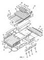
- FIG. 3is an exploded view of the bladder assembly of the mattress shown in FIG. 2 ;
- FIG. 4is a side elevation view of the frame of FIG. 1 moved to a flat configuration
- FIG. 5is a side elevation view of the frame of FIG. 4 showing that a deck of the frame can be moved to other configurations to support a mattress in a number of arrangements as shown in FIG. 1 ;
- FIG. 6is a diagrammatic view of the patient-support apparatus of FIG. 1 showing that the patient-support apparatus includes a control system;
- FIG. 7is a diagram showing a routine performed by the control system of the patient-support apparatus
- FIG. 8is a diagram showing a subroutine of the routine shown in FIG. 7 performed by the control system of the patient-support apparatus;
- FIG. 9is a diagram showing a subroutine of the routine shown in FIG. 7 performed by the control system of the patient-support apparatus;
- FIG. 10is a diagrammatic view of a data analysis system including a number of patient-support apparatuses located in hospital networks, the data analysis system configured to collect information from each of the patient-support apparatuses and to analyze the information to generate algorithms for calculating operating parameters for the patient-support apparatuses;
- FIG. 11is a flow chart showing a routine performed by a hospital information system included in each of the hospital networks of FIG. 10 ;
- FIG. 12is a flow chart showing a routine performed by a central information center included in the data analysis system of FIG. 10 .
- a patient-support apparatussuch as a hospital bed 10 , for example, includes a mattress 12 and a frame 14 as shown in FIG. 1 .
- the hospital bed 10has a head end 16 and a foot end 18 .
- the mattress 12is supported on the frame 14 .
- the hospital bed 10is a TotalCare® bed marketed by Hill-Rom Company, Inc.
- the mattress 12includes an air bladder assembly 20 , as shown in FIGS. 2 and 3 , that is inflated and deflated to change the pressure profile of the mattress 12 when the mattress 12 is supporting a patient lying on the bed 10 .
- the frame 14is movable between a flat configuration, as shown in FIG.
- a patient-support apparatusmay be just a mattress with a control system, a frame with a control system, or another device for supporting a patient.
- the bed 10includes a control system 22 as shown diagrammatically in FIG. 6 .
- the control system 22is configured to receive information about a patient supported on the bed 10 from sensors in the bed 10 and to create a patient-specific profile corresponding to the patient supported on the bed 10 .
- the control system 22is configured to update the patient-specific profile corresponding to the patient and to adjust the pressure in the in the air bladder assembly 20 based on the updated patient-specific profile to optimize a patient outcome.
- the illustrative control system 22performs a control routine 200 to reduce migration of the patient toward the foot end 18 of the bed 10 and to modify operation of the bed 10 to optimize other patient outcomes such as patient restlessness and patient mobility.
- the bed 10illustratively includes a number of barriers 15 coupled to the frame 14 and a number of wheels 85 supporting the frame 14 as shown in FIG. 1 .
- the barriers 15illustratively include a footboard 17 , a headboard 19 , a pair of siderails 21 , and a pair of headrails 23 .
- the footboard 17is located at the foot end 18 of the bed 10 .
- the headboard 19is located at the head end 16 of the bed 10 .
- the siderails 21extend along sides 25 , 27 of the bed 10 and are movable between a blocking position extending above the mattress 12 and an exit position lower than the blocking position and configured to allow a patient to enter or exit the bed 10 .
- the headrails 23are located along the sides 25 , 27 of the bed 10 near the head end 16 of the bed 10 .
- the mattress 12illustratively includes a lower cover 24 , a coverlet 26 , a heat barrier 28 , and the air bladder assembly 20 .
- the lower cover 24receives the air bladder assembly 20 .
- the coverlet 26couples to the lower cover 24 via a zipper (not shown) to enclose the air bladder assembly 20 when the mattress 12 is assembled.
- the heat barrier 28surrounds the air bladder assembly 20 when the air bladder assembly 20 is enclosed by the coverlet 26 .
- the air bladder assembly 20includes a head cushion 30 , a torso cushion 32 , a seat cushion 34 , and a foot cushion 36 as shown in FIG. 2 .
- the head cushion 30includes a number of inflatable bladders 31 that extend longitudinally along the length of the mattress 12 .
- the torso cushion 32includes a number of inflatable bladders 33 that extend laterally across the mattress 12 between the sides 25 , 27 of the bed 10 .
- the seat cushion 34includes a number of inflatable bladders 35 that extend laterally across the mattress 12 .
- the foot cushion 36includes a number of inflatable bladders 37 that extend laterally across the mattress 12 .
- the bladders 31 , 33 , 35 , 37are independently inflatable and deflatable so that the pressure along the mattress 12 can be controlled to produce specific pressure profiles.
- Different pressure profiles of the bladders 31 , 33 , 35 , 37can be produced in an effort to induce different patient outcomes.
- the inflatable bladders 35 of the seat section 34may be inflated to form a wedge or a dynamic wave as described in U.S. application Ser. No. 13/314,501 published as U.S. Pub. No. 2013/0145552 A1, herein incorporated by reference.
- the pressure profile of the bladdersmay produce other shapes or desired interface pressures along the patient to achieve other patient outcomes.
- the air bladder assembly 20also includes a percussion and vibration assembly 38 , a body rotation assembly 40 , and a foot rotation assembly 42 .
- the percussion and vibration assembly 38includes inflatable bladders 39 configured to apply percussion and/or vibration therapy to a patient supported on the mattress 12 to dislodge fluid in the patient's lungs or for other therapeutic purposes.
- the body rotation assembly 40includes a left and a right working bladder 44 , 45 and a left and a right turn bladder 46 , 47 .
- the bladders 44 , 45 , 46 , 47 of the body rotation assembly 40are configured to inflate and deflate to apply rotation therapy to a patient supported on the mattress 12 and to rotate the patient for linen changes or the like.
- the foot rotation assembly 42includes a number of bladders 43 configured to inflate and deflate to apply rotation therapy to a patient's feet when the patient is supported on the mattress 12 .
- the air bladder assembly 20also includes a lower support 51 , a number of side bolsters 53 , and a number of locating pads 55 .
- the lower support 51includes a head support 57 located to underlie and support the head cushion 30 of the air bladder assembly 20 .
- the side bolsters 53are illustratively made from foam and are arranged to fill the space between the mattress 12 and the frame 14 when the mattress 12 is supported on the frame 14 .
- the locating pads 55are coupled to the side bolsters 53 and are located to engage the frame 14 to locate the mattress 12 on the frame 14 .
- the frame 14is configurable so that a patient supported on the bed 10 can be supported in a variety of positions as shown in FIGS. 4 and 5 .
- the frame 14includes a lower frame 48 , an upper frame 50 , and a pivotable deck 52 .
- the upper frame 50is supported over the lower frame 48 by a pair of arms 54 , 56 as shown in FIG. 4 .
- the pair of arms 54 , 56pivot to move the upper frame 50 relative to the lower frame 48 as shown in FIG. 5 .
- the deck 52is coupled to the upper frame 50 and is movable relative to the upper frame 50 .
- the deck 52is movable to a number of predetermined configurations and illustratively includes a head deck section 58 , a seat deck section 60 , a thigh deck section 62 , and a foot deck section 64 as shown in FIG. 5 .
- the head deck section 58is pivotably coupled to the seat deck section 60 and moves between a flat position and a number of inclined positions. When the head deck section 58 is in the inclined position, an angle ⁇ is formed between the head deck section 58 and the upper frame 50 as shown in FIG. 5 .
- the seat deck section 60is coupled to the upper frame 50 and moves therewith.
- the thigh deck section 62is pivotably coupled to the seat deck section 60 and is spaced apart from the head deck section 58 .
- the foot deck section 64is pivotably coupled to the thigh deck section 62 and extends out from the upper frame 50 .
- the control system 22 of the bed 10is shown diagrammatically in FIG. 6 .
- the control system 22includes an air system 66 , deck drives 68 , a controller 70 , a user interface 72 , and a transceiver 73 .
- the air system 66is operable to inflate or deflate the bladders of the mattress 12 to change the pressure profile of the mattress 12 .
- the deck drives 68are configured to move the head deck section 58 , the thigh deck section 62 , and the foot deck section 64 so that the deck 52 is movable among a variety of configurations.
- the controller 70includes a memory 74 for storing instructions and data, a timer 75 , and a processor 76 for executing instructions stored in the memory 74 and for writing additional data to the memory 74 .
- the controller 70is electrically coupled to the air system 66 and the deck drives 68 to direct operation of the air system 66 and the deck drives 68 .
- the user interface 72 and the transceiver 73are also electrically coupled to the controller 70 .
- the user interface 72illustratively includes a touch-sensitive display 78 for displaying and receiving information and a keypad input 80 for receiving inputs from the user.
- the user interface 72is coupled to the siderails 21 of the bed 10 as shown in FIG. 1 .
- the user interface 72is operable to control entertainment devices such as televisions and radios, to operate the air system 66 to increase or decrease the firmness/pressure in the mattress 12 , and to change the configuration of the deck 52 .
- the transceiver 73is configured to transmit and receive information over a network.
- the networkmay use any of a number of hardware and communications protocols.
- the networkis configured as a peer-to-peer network.
- the networkmay be configured in a master and slave configuration.
- the transceiver 73may be replaced by separate transmitters and receivers.
- the transceiver 73may also be a wired device coupled to a network as is known in the art.
- the control system 22also has a number of sensors for detecting information about a patient supported on the bed 10 as shown diagrammatically in FIG. 6 .
- the control system 22includes pressure sensors 131 , 133 , 135 , 137 , a plurality of position sensors 82 , and a plurality of load cells 84 each electrically coupled to the controller 70 .
- the pressure sensors 131 , 133 , 135 , 137are configured to detect the pressure in the bladders 31 , 33 , 35 , and 37 of the air bladder assembly 20 , respectively.
- the position sensors 82are illustratively accelerometers (not shown) and contact switches (not shown). In other embodiments, other switches or sensors may be used including non-contact proximity switches as well as potentiometers, for example.
- the accelerometersare coupled to the deck sections 58 , 60 , 62 , 64 and are configured to measure the angle of each deck sections 58 , 60 , 62 , 64 relative gravity. Accelerometers may also be used to determine the tilt of the upper frame 50 .
- the contact switchesare coupled to the siderails 21 and are configured to detect if the siderails 21 are in the blocking position or the exit position.
- the load cells 84are illustratively coupled between the deck 52 and the upper frame 50 . The load cells 84 are configured to measure the weight of a patient supported on the bed 10 .
- the air system 66includes a manifold 86 , an exhaust 88 , and a source of pressurized air 90 as shown in FIG. 6 .
- the manifold 86is coupled to each of the bladders 31 , 33 , 35 , 37 , the exhaust 88 , and the source of pressurized air 90 .
- the exhaust 88is in open fluid communication with the atmosphere around the bed 10 .
- the source of pressurized air 90is illustratively a compressor but in other embodiments may be a blower, an air tank, or another source of pressurized air.
- the manifold 86includes a number of valves (not shown) and is configured to selectively couple each bladder 31 , 33 , 35 , 37 to the exhaust 88 , the source of pressurized air 90 , or to close the bladder 31 , 33 , 35 , 37 .
- the manifold 86is operated to couple a bladder 31 , 33 , 35 , 37 to the exhaust 88 , the bladder 31 , 33 , 35 , 37 deflates so that the pressure in the bladder 31 , 33 , 35 , 37 is reduced.
- the manifold 86When the manifold 86 is operated to couple a bladder 31 , 33 , 35 , 37 to the source of pressurized air 90 , the bladder 31 , 33 , 35 , 37 inflates so that pressure in the bladder 31 , 33 , 35 , 37 is increased. When the manifold 86 is operated to close the bladder 31 , 33 , 35 , 37 the pressure in the bladder 31 , 33 , 35 , 37 is substantially maintained unless a patient supported on the bladders 31 , 33 , 35 , 37 shifts the weight supported by the bladder 31 , 33 , 35 , 37 .
- a routine 200 for setting operating parameters of the bed 10 to reduce patient migration toward the foot end 18 of the bed 10is performed by the controller 70 as shown.
- the controller 70retrieves a baseline patient-specific profile including information specific to a patient supported on the bed 10 .
- the baseline patient-specific profileis illustratively retrieved from the memory 74 of the controller 70 .
- information included in the baseline patient-specific profilemay be received by the transceiver 73 from an external data source such as an EMR (electronic medical record), input via the input 80 of the user interface 72 , or detected by one or more of the sensors 131 , 133 , 135 , 137 , 82 , 84 coupled to the controller 70 .
- EMRelectronic medical record
- the patient-specific profile of a patientincludes one or more pieces of information about the patient supported on the bed 10 .
- Information about the patientmay include age, sex, weight, height, and the like.
- calculated information about patient outcomesis also included in the patient-specific profile. Calculated information about patient outcomes include, for example, rates of patient migration toward the foot end 18 of the bed 10 , patient mobility factors, and patient restlessness factors.
- Other information about the patientmay also be included in the patient-specific profile such as caregiver assessed skin condition factors, caregiver assessed acuity factors, patient disorders, patient ailments, and time of therapy application (rotation, percussion, and/or vibration).
- the rate of patient migration toward the foot end 18 of the bed 10is calculated based on the determined position of the patient on the bed 10 over time.
- patient positionis determined by pressures detected in the bladders 31 , 33 , 35 , 37 of the air bladder assembly 20 and/or by weight distribution detected by the load cells 84 .
- An illustrative method of determining patient positionis more fully described in U.S. Patent Publication No. 2008-0189865, which is hereby incorporated by reference.
- the position of a patientmay be determined as described in U.S. Pat. No. 6,822,571, U.S. Pat. No. 7,253,366, or U.S. Pat. No. 6,208,250, each hereby incorporated by reference herein.
- the patient mobility factoris illustratively calculated based on the number of times the patient is determined to be out of the bed 10 , as indicated by the load cells 84 , and on the amount of time the patient spends in an inclined position, as indicated by the position sensors 82 .
- the patient restlessness factoris illustratively calculated based on the number of times a patient adjusts the firmness of the mattress 12 , as indicated by the user interface 72 and the pressure sensors 131 , 133 , 135 , 137 , and the number of times a patient adjusts his position on the bed 10 , as indicated by the pressure sensors 131 , 133 , 135 , 137 .
- other inputscontribute to the calculation of the patient mobility factor and the patient restlessness factor.
- the controller 70calculates a series of baseline operating parameters for the bed 10 illustratively including target pressure profiles for the bladders 31 , 33 , 35 , 37 corresponding to different positions of the deck 52 , maximum and minimum allowed pressure ranges for the bladders 31 , 33 , 35 , 37 at each position of the deck 52 , and allowed configurations of the deck 52 .
- Each operating parameteris calculated in a multivariable algorithm based on the available patient-specific information each multiplied by a respective coefficient.
- the operating parameters for the bed 10may be based on a patient-specific profile that does not include calculated patient-specific information to indicate that they are unavailable.
- OPis one operating parameter of the bed 10
- C OPis a coefficient for calculating operating parameters
- PFis a patient factor from the patient-specific profile.
- Some of the patient factors from the patient-specific profileare constant in response to bed operating parameters. For example, a patient's age, sex, and weight are constant. Other patient factors are dependent on changes in bed operating parameters. For example, rates of patient migration toward the foot end 18 of the bed 10 , patient mobility factors, and patient restlessness factors may vary over time depending on the operating parameters of the bed 10 .
- the controller 70adjusts the pressures in the mattress 12 to match the target pressures for the current configuration of the frame 14 included in the baseline operating parameters by operating the air system 66 included in the control system 22 .
- the controller 70also begins controlling to the maximum and minimum pressure ranges for the bladders 31 , 33 , 35 , 37 at each position of the deck 52 and begins enforcing the allowed configurations of the deck 52 (moving the deck 52 if currently outside the allowed configurations).
- available pressure ranges and/or deck configurationsare illuminated or displayed on the user interface 72 and unavailable pressure ranges and/or deck configurations are darkened or removed from the user interface 72 .
- step 204the controller 70 calculates the migration of the patient toward the foot end 18 of the bed 10 over a predetermined amount of time. Following the calculation of migration, the calculated migration of the patient is compared to an expected patient outcome range corresponding to a range of migration values in decision step 205 .
- MP EXPECTEDis the expected amount of patient migration
- C MPis a coefficient for calculating migration of the patient
- PFis a patient factor from the patient-specific profile
- OPis an operating parameter of the bed 10 .
- the upper and lower ends of the expected patient migration outcome rangemay be determined to be a statistically significant number of values above and below the expected value. In other embodiments, two equations may be used to establish upper and lower ends of the range.
- step 206updates the patient-specific profile to include the calculated amount of patient migration and stores the updated patient-specific profile in the memory 74 .
- the controller 70performs step 207 A performing a multivariable analysis, such as regression analysis, based on the equation used to calculate the expected patient migration and the actual patient migration to learn which operating parameters are likely to affect the measured patient outcome.
- step 207 Bthe controller 70 updates the coefficients used to determine operating parameters and the expected patient migration outcome based on the learned information about the specific patient.
- the algorithmlearns and responds to the specific patient by updating the coefficients.
- the updated set of operating parametersmay differ from the baseline operating parameters even though the migration calculated is equal to an expected migration value.
- the updated set of operating parametersmay allow a wider range of selectable pressures in the mattress 12 or allow additional configurations of the frame 14 to be selected by the patient or the caregiver if the patient's migration is within the expected migration values for a set period of time.
- the updated set of operating parametersmay be adjusted to affect changes in other patient outcomes, for example minimizing patient restlessness, maximizing patient mobility, or reducing the likelihood of bed sores by reducing interference pressures.
- the controller 70modifies operating parameters to optimize the impact on the patient. For example, a highly mobile patient has a reduced opportunity for development of bed sores because the patient is not likely to be bedridden. If a patient is mobile, but restless while in the bed, the algorithm may infer that the mattress pressures are uncomfortable to the patient and the restlessness is an artifact of discomfort. In such a situation, the algorithm will optimize the pressure for comfort and not interface pressure control.
- step 207 Cthe controller calculates updated operating parameters based on the updated multivariable equation.
- step 208 of routine 200the controller 70 adjusts the pressures in the mattress 12 to match the target pressures for the current configuration of the frame 14 included in the updated operating parameters by operating the air system 66 included in the control system 22 .
- the controller 70also begins enforcing updated maximum and minimum pressure ranges for the bladders 31 , 33 , 35 , 37 at each position of the deck 52 and begins enforcing the allowed configurations of the deck 52 (moving the deck 52 if currently outside the allowed configurations).
- newly available pressure ranges and/or deck configurationsare illuminated or displayed on the user interface 72 and newly unavailable pressure ranges and/or deck configurations are darkened or removed from the user interface 72 to provide an indication of availability.
- the baseline patient-specific profile, the baseline operating parameters, the updated patient-specific profile, and the updated operating parametersare transmitted by the transceiver 73 .
- the transmitted informationmay be received by an external data center where it may be stored for additional processing and analysis. In other embodiments, the transmitted information may be stored in the memory 74 of the bed 10 or transmitted to another data storage device for additional analysis.
- step 210the updated patient-specific profile is stored as the new baseline patient-specific profile completing an iteration of the routine 200 .
- the routine 200loops back to step 204 to calculate migration of the patient toward the foot end 18 of the bed 10 while the bed 10 operates using operation parameters corresponding to the new baseline patient-specific profile.
- the controller 70learns about a patient supported on the bed 10 and can refine equation coefficients and operating parameters to obtain a number of desired patient outcomes such as minimized migration toward the foot end 18 of the bed 10 , minimized patient restlessness, maximized patient mobility, and minimized chance of bed sores.
- step 212 of subroutine 211the controller 70 compares the baseline patient-specific profile and calculated amount of patient migration to a number of likely reasons for the difference. For example, if the calculated migration exceeds the expected range of migration values, the patient may have been recently sedated or medicated, may have been sleeping during normal waking hours, or may have a disorder or ailment consistent with excessive migration toward the foot end 18 of the bed 10 .
- the patientmay have been coming out of a sedated state, may have been awake during normal sleeping hours, or may have a disorder or ailment consistent with lack of migration toward the foot end 18 of the bed 10 .
- the controller 70determines the likely reason or reasons for the calculated migration values to fall outside the expected range, the controller 70 proceeds to step 213 of subroutine 211 and directs the display 78 of the user interface 72 to show the reason(s) for review by a caregiver, a patient, or other user and prompts the user to select the applicable reason.
- decision step 214the controller 70 determines if it has received an input indicating a selection of one or more of the reasons from the input 80 of the user interface 72 during a predetermined response time. If the controller 70 has received an input during the response time, the controller 70 exits the subroutine 211 and proceeds to step 206 updating the baseline patient-specific profile with information corresponding to both the calculated amount of patient migration and the reasons selected explaining the unexpected migration.
- the controller 70proceeds to step 215 and resets the display 78 of the user interface 72 before exiting the subroutine 211 and proceeding to step 206 to update the baseline patient-specific profile with the calculated amount of patient migration.
- the controller 70can identify patient conditions relevant to the calculation of operating parameters (such as restless leg syndrome, bed sores, and the like) and can disregard information corresponding to incidental factors.
- routine 200also includes subroutine 220 for optimizing the patient mobility outcomes while maintaining patient migration outcome within the expected range.
- the controller 70calculates a mobility factor for a patient supported on the bed 10 .
- the calculated mobility factoris illustratively based on the number of times the patient exits/enters the bed 10 (indicated by the load cells 84 and/or by the raising and lowering of the siderails 21 ).
- other data input through the user interface 72 or received by the transceiver 73may be used to calculate mobility factor.
- the controller 70compares the calculated mobility factor to an expected (optimized) range of mobility factor values. If the calculated mobility factor is equal to an expected mobility factor value (the expected value illustratively calculated using a multivariable equation similar to the equation used to calculate expected patient migration), then the subroutine 220 advances to step 206 of routine 200 so that the baseline patient-specific profile is updated to include the calculated mobility factor before looping back to repeat subroutine 220 . If the calculated mobility factor determined in decision step 222 is not equal to one of the expected mobility factor values, the subroutine 220 advances to step 223 .
- an expected mobility factor valuethe expected value illustratively calculated using a multivariable equation similar to the equation used to calculate expected patient migration
- the controller 70compares the baseline patient-specific profile and calculated mobility factor to a number of likely reasons for the difference between the calculated mobility factor and the expected mobility factor.
- the calculated mobility factormay be greater than or less than the expected range of mobility factors in response to the patient having an improving/deteriorating acuity score, responding to diet or medication, having been moved a number of times for tests or procedures, or having trouble sitting up on a low pressure or “soft” mattress 12 .
- step 224 of subroutine 220directs the display 78 of the user interface 72 to show the reason(s) for review by a caregiver, a patient, or other user and prompts the user to select the applicable reason.
- decision step 225the controller 70 determines if it has received an input indicating a selection of one or more of the reasons from the user interface 72 during a predetermined response time. If the controller 70 has received a selection during the response time, the controller 70 proceeds to step 206 of routine 200 and updates the baseline patient-specific profile with information corresponding to both the calculated mobility factor and the reasons selected for the unexpected mobility. If the controller 70 has not received an input during the response time, the controller 70 proceeds to step 226 and resets the display 78 of the user interface 72 before moving on to step 206 of routine 200 and updating the baseline patient-specific profile with the calculated mobility factor outside the expected range.
- the controller 70may modify parameters in the updated operational parameters calculated in step 207 in an effort to optimize the mobility factor controlling for an expected amount of migration toward the foot end 18 of the bed 10 .
- the updated operational parametersmay include a target pressure profile with an increased pressure in the seat cushion 34 of the mattress 12 to make exiting the bed 10 easier for a patient thereby encouraging an increase in the calculated mobility factor.
- the controller 70may ignore the calculated mobility factor if mobility factors outside the expected range correspond to reasons external to the bed 10 (such as movements from the bed for tests) selected by a caregiver, user, or patient.
- routine 200also includes subroutine 230 for optimizing the patient restlessness outcomes while maintaining patient migration outcome within the expected range.
- the controller 70calculates a restlessness factor for a patient supported on the bed 10 .
- the calculated restlessness factoris illustratively based on a sensed in-bed movement during normal sleeping hours using information from the load cells 84 indicating movement.
- the restlessness calculationmay include a parameter corresponding to the number of times a patient repositions himself as indicated by adjustments to the bladders 31 , 33 , 35 , 37 of the mattress 12 to maintain a pressure profile.
- the restlessness calculationincludes the amount of time the frame 14 is in an inclined position and the frequency of frame movement as measured by the position sensors 82 . Further, the illustrative restlessness calculation includes the number of times a patient adjusts entertainment devices (not shown) using the user interface 72 . In other embodiments, additional parameters input through the user interface 72 or received by the transceiver 73 may be used to calculate restlessness factor.
- the frequency of bed adjustment, and the times of entertainment device use itcan be deduced whether or not a patient is resting in one place consistent with restful sleep.
- Patient restlessnessis interdependent with other patient outcomes and therefore modifying operating parameters to optimize patient restlessness may impact other patient outcomes.
- low mattress pressurescan decrease restlessness.
- very low mattresses pressurescan depress mobility by making patient bed exits harder to accomplish. If it is known that a patient is highly mobile and performs multiple bed exits per day, the algorithm may infer that very low mattress pressures are unlikely to compromise mobility when pressure is reduced. In such a situation, the algorithm will optimize the pressures to reduce restlessness by reducing mattress pressures and will not optimize for mobility.
- the controller 70compares the calculated restlessness factor to an expected (optimized) range of restlessness factor values. If the calculated restlessness factor is equal to an expected restlessness factor value (the expected value illustratively calculated using a multivariable equation similar to the equation used to calculate expected patient migration), then the subroutine 230 sends information to step 206 of routine 200 so that the baseline patient-specific profile is updated to include the calculated restlessness factor before looping back around to repeat subroutine 230 . If the calculated restlessness factor is determined in decision step 232 to not equal to one of the expected restlessness factor values, the subroutine 230 advances to step 233 .
- an expected restlessness factor valuethe expected value illustratively calculated using a multivariable equation similar to the equation used to calculate expected patient migration
- the controller 70compares the baseline patient-specific profile and calculated restlessness factor to a number of likely reasons for the difference between the calculated restlessness factor and the expected restlessness factor.
- the calculated restlessness factormay be greater than or less than the expected range of restlessness factors because of recent patient surgery, a rash or other skin condition, or the patient being uncomfortable on the mattress 12 .
- step 234 of subroutine 230the controller 70 determines if it has received an input indicating a selection of one or more of the reasons from the user interface 72 during a predetermined response time. If the controller 70 has received an input during the response time, the controller 70 proceeds to step 206 of routine 200 and updates the baseline patient-specific profile with information corresponding to both the calculated restlessness factor and the reasons selected for the unexpected restlessness before looping to repeat subroutine 230 .
- step 236the controller 70 updates the baseline patient-specific profile with the calculated restlessness factor outside the expected range before looping to repeat subroutine 230 .
- the controller 70may modify parameters in the updated operational parameters calculated in step 207 in an effort to optimize the restlessness factor while maintaining the expected amount of migration toward the foot end 18 of the bed 10 .
- the updated operational parametersmay include a target pressure profile with a decreased pressure in the foot cushion 36 of the mattress 12 to make the bed 10 more comfortable for a patient thereby encouraging a decrease in the calculated restlessness factor.
- the controller 70may ignore the calculated restlessness factor if restlessness factors outside the expected range correspond to reasons external to the bed 10 (such as new medication) selected by a caregiver, user, or patient.
- Additional subroutinescan be implemented to optimize additional patient outcomes by updating operational parameters in response to unexpected (un-optimized) outcomes. For example, additional subroutines can optimize for low interface pressure between the mattress 12 and a patient. Using a multivariable analysis, each patient outcome can be optimized while controlling for other patient outcomes.
- a data analysis system 300for collecting and analyzing data collected from a number of beds 10 A, 10 B, 10 C, 10 D, 10 E, 10 F, 10 G, 10 H, 10 I is shown.
- Each bed 10 A, 10 B, 10 C, 10 D, 10 E, 10 F, 10 G, 10 H, 10 Iis substantially similar to the bed 10 described above.
- a number of different bed modelsmay be incorporated into the data analysis system 300 .
- the data analysis system 300illustratively includes a number of hospital networks 302 A, 302 B, 302 C and a central information center 304 .
- Each of the hospital networks 302 A, 302 B, 302 Care in two way communication with the central information center 304 .
- the central information center 304is illustratively a number of real or virtualized computer servers coupled to a communication network and configured to store and process data.
- Each hospital network 302 A, 302 B, 302 Cmay be located in a single building or may be spread across a number of hospital buildings, administrative buildings, clinics, pharmacies, and/or nursing homes. Illustratively, each hospital network 302 A, 302 B, 302 C is substantially similar and therefore only hospital network 302 A is described further.
- the hospital network 302 Aillustratively includes a number of beds 10 A, 10 B, 10 C and a hospital information system 306 A. Each bed 10 A, 10 B, 10 C is in two way communication with the hospital information system 306 A via transceiver 73 .
- the hospital information system 306is illustratively a number of real or virtualized computer servers coupled to a communication network and configured to store and process data.
- each bed 10transmits patient information and corresponding operating parameter information in step 209 of the routine 200 .
- the hospital information system 306 Aperforms a routine 400 to process the information as shown in FIG. 10 .
- the hospital information system 306 Areceives the patient information and corresponding operating parameter information from the beds 10 A, 10 B, 10 C.
- the hospital information system 306 Apopulates a database including information from a number of beds 10 included in the hospital network 302 A as shown in step 402 .
- the hospital information system 306 AIn step 403 , the hospital information system 306 A generates reports including information about patients in the hospital network 302 A including migration, patient restlessness, patient mobility or other patient outcomes based on data in the populated database. Additionally, the hospital information system 306 A compiles reports including information about caregiver attentiveness to prompts displayed on the user interface 72 . The compiled reports are available to be retrieved by users of the hospital information system 306 A on user devices 305 A in communication with the hospital information system 306 A such as personal computers, PDAs, mobile phones, or on other user interfaces around the hospital network 302 A.
- the hospital information system 306 Acommunicates with the central information center 304 to transmit data from the populated database to the central information center 304 .
- the hospital information system 306 Areceives new algorithms for calculating operating parameters of the beds 10 A, 10 B, 10 C. The new algorithms are adapted based on the collective information acquired from multiple hospitals.
- the hospital information system 306populates the new algorithms on each controller 70 of each of the beds 10 A, 10 B, 10 C in the hospital network 302 A as shown in step 406 of routine 400 . Steps 405 and 406 of routine 400 may be repeated at regular intervals to ensure that the beds 10 A, 10 B, 10 C are updated with the newest algorithms for setting operational parameters.
- the central information center 304performs a routine 500 to analyze the data collected from beds 10 A, 10 B, 10 C, 10 D, 10 E, 10 F, 10 G, 10 H, 10 I and to generate new algorithms for setting operating parameters for the beds 10 A, 10 B, 10 C, 10 D, 10 E, 10 F, 10 G, 10 H, 10 I.
- Routine 500uses multivariate analysis of the variance detected in the calculated patient outcomes to adjust the coefficients used to calculate expected outcomes for the beds 10 A, 10 B, 10 C, 10 D, 10 E, 10 F, 10 G, 10 H, 10 I.
- the central information center 304receives data from each hospital information system 306 A, 306 B, 306 C.
- the central information center 304populates a central database with patient information and corresponding applied operating parameters.
- the central information center 304 of the illustrative embodimentuses data from the populated central database, the central information center 304 of the illustrative embodiment applies multivariate analytics, such as regression analysis, and multivariate statistical analysis to determine what operating parameters (independent variables) are likely to have effects on the measured or calculated patient outcomes (dependent variables) as shown in step 503 . Because the central information center 304 analyzes data from a large number of beds with different patient specific information, the analysis of effective operating parameters may be more robust than a single bed 10 or single hospital network 302 A, 302 B, 302 C analysis.
- the central information center 304determines interactions among the patient-specific profiles and the calculated patient outcomes (independent variables). Comparing large numbers of patient-specific profiles with different amounts of information and calculated patient outcomes allows the central information center 304 to identify trends among certain types of patients and to identify potential reasons for unexpected patient responses. For example, if a patient-specific profile does not indicate that a patient is incontinent but the patient's outcomes such as sustained high mobility and restlessness are consistent with the patient outcomes of other patients whose profile include incontinence, the central information center 304 can associate incontinence as a selectable reason for unexpected outcomes for future patients with a similar profile.
- the central information center 304also determines interactions among the operating parameters. Comparing large numbers of operating parameters the central information center 304 is able to identify combinations of parameters that resulted in expected, optimized outcomes. From these analyses, the central information center 304 develops a master profile for how patient outcomes are affected when a patient is subjected to different operating parameters.
- the central information center 304In step 506 , the central information center 304 generates new algorithms for calculating operating parameters based on patient-specific profile information and new algorithms for calculating expected patient outcomes. The new algorithms are then transmitted back to each bed 10 A, 10 B, 10 C, 10 D, 10 E, 10 F, 10 G, 10 H, 10 I through the hospital information systems 306 A, 306 B, 306 C in step 507 . The new algorithms are applied when the controllers 70 of the beds 10 A, 10 B, 10 C, 10 D, 10 E, 10 F, 10 G, 10 H, 10 I perform routine 200 to optimize patient outcomes.
- each hospital network 302 A, 302 B, 302 Creceives new algorithms for calculating operating parameters as part of a subscription service.
- the subscription serviceis offered by the operator of the central information center 304 .
- each hospital information system 306 A, 306 B, 306 Cmay be configured to use artificial intelligence to learn about individual patient reactions and to generate new algorithms for calculating updated operating parameters based on information from the hospital network 302 A, 302 B, 302 C corresponding to the hospital information systems 306 A, 306 B, 306 C.
Landscapes
- Health & Medical Sciences (AREA)
- Life Sciences & Earth Sciences (AREA)
- General Health & Medical Sciences (AREA)
- Animal Behavior & Ethology (AREA)
- Veterinary Medicine (AREA)
- Public Health (AREA)
- Nursing (AREA)
- Medical Informatics (AREA)
- Pathology (AREA)
- Biomedical Technology (AREA)
- Heart & Thoracic Surgery (AREA)
- Oral & Maxillofacial Surgery (AREA)
- Molecular Biology (AREA)
- Surgery (AREA)
- Engineering & Computer Science (AREA)
- Physiology (AREA)
- Biophysics (AREA)
- Dentistry (AREA)
- Physics & Mathematics (AREA)
- Invalid Beds And Related Equipment (AREA)
- Accommodation For Nursing Or Treatment Tables (AREA)
Abstract
Description
OPA=COP1PF1+COP2PF2+COP3PF3. . .
In the illustrative form, OP is one operating parameter of the
MPEXPECTED=CMP1PF1+CMP2PF2+CMP3PF3. . . CMPAOPA+CMPBOPB. . .
In the illustrative form, MPEXPECTEDis the expected amount of patient migration, CMPis a coefficient for calculating migration of the patient, PF is a patient factor from the patient-specific profile, and OP is an operating parameter of the
Claims (22)
Priority Applications (5)
| Application Number | Priority Date | Filing Date | Title |
|---|---|---|---|
| US13/314,669US8973186B2 (en) | 2011-12-08 | 2011-12-08 | Optimization of the operation of a patient-support apparatus based on patient response |
| AU2012261500AAU2012261500A1 (en) | 2011-12-08 | 2012-11-30 | Optimization of the operation of a patient-support apparatus based on patient response |
| EP12195522.3AEP2601925A3 (en) | 2011-12-08 | 2012-12-04 | Optimization of the operation of a patient-support apparatus based on patient response |
| JP2012267436AJP2013119038A (en) | 2011-12-08 | 2012-12-06 | Optimization of operation of patient-holding device based on patient response |
| US14/618,142US10391009B2 (en) | 2011-12-08 | 2015-02-10 | Optimization of the operation of a patient-support apparatus based on patient response |
Applications Claiming Priority (1)
| Application Number | Priority Date | Filing Date | Title |
|---|---|---|---|
| US13/314,669US8973186B2 (en) | 2011-12-08 | 2011-12-08 | Optimization of the operation of a patient-support apparatus based on patient response |
Related Child Applications (1)
| Application Number | Title | Priority Date | Filing Date |
|---|---|---|---|
| US14/618,142ContinuationUS10391009B2 (en) | 2011-12-08 | 2015-02-10 | Optimization of the operation of a patient-support apparatus based on patient response |
Publications (2)
| Publication Number | Publication Date |
|---|---|
| US20130145558A1 US20130145558A1 (en) | 2013-06-13 |
| US8973186B2true US8973186B2 (en) | 2015-03-10 |
Family
ID=47290732
Family Applications (2)
| Application Number | Title | Priority Date | Filing Date |
|---|---|---|---|
| US13/314,669Active2033-02-25US8973186B2 (en) | 2011-12-08 | 2011-12-08 | Optimization of the operation of a patient-support apparatus based on patient response |
| US14/618,142Active2032-08-18US10391009B2 (en) | 2011-12-08 | 2015-02-10 | Optimization of the operation of a patient-support apparatus based on patient response |
Family Applications After (1)
| Application Number | Title | Priority Date | Filing Date |
|---|---|---|---|
| US14/618,142Active2032-08-18US10391009B2 (en) | 2011-12-08 | 2015-02-10 | Optimization of the operation of a patient-support apparatus based on patient response |
Country Status (4)
| Country | Link |
|---|---|
| US (2) | US8973186B2 (en) |
| EP (1) | EP2601925A3 (en) |
| JP (1) | JP2013119038A (en) |
| AU (1) | AU2012261500A1 (en) |
Cited By (16)
| Publication number | Priority date | Publication date | Assignee | Title |
|---|---|---|---|---|
| US20140047645A1 (en)* | 2011-12-05 | 2014-02-20 | Ceragem Cellupedic. Co., Ltd | Mattress and method of adjusting pressure of mattress |
| US20140331412A1 (en)* | 2008-03-15 | 2014-11-13 | Stryker Corporation | Force sensing sheet |
| US20150150739A1 (en)* | 2011-12-08 | 2015-06-04 | Hill-Rom Services, Inc. | Optimization of the operation of a patient-support apparatus based on patient response |
| US9308393B1 (en) | 2015-01-15 | 2016-04-12 | Dri-Em, Inc. | Bed drying device, UV lights for bedsores |
| US20160270547A1 (en)* | 2015-03-20 | 2016-09-22 | Apex Medical Corp. | Air mattress system and inflation and deflation pressure regulation system and method |
| US9901503B2 (en) | 2008-03-13 | 2018-02-27 | Optimedica Corporation | Mobile patient bed |
| US10045715B2 (en) | 2015-04-27 | 2018-08-14 | Hill-Rom Services, Inc. | Self-compensating bed scale system for removable components |
| US10054479B2 (en) | 2015-05-05 | 2018-08-21 | Hill-Rom Services, Inc. | Bed with automatic weight offset detection and modification |
| US10413464B2 (en) | 2015-05-05 | 2019-09-17 | Hill-Rom Services, Inc. | Multi-mode sacral unloading pressure relief in a patient support surface |
| US10634549B2 (en) | 2016-02-11 | 2020-04-28 | Hill-Rom Services, Inc. | Hospital bed scale calibration methods and patient position monitoring methods |
| US11052005B2 (en) | 2017-09-19 | 2021-07-06 | Stryker Corporation | Patient support apparatus with handles for patient ambulation |
| US11116680B2 (en) | 2017-09-19 | 2021-09-14 | Stryker Corporation | Patient support apparatus for controlling patient ingress and egress |
| US11160705B2 (en) | 2017-10-20 | 2021-11-02 | Stryker Corporation | Adjustable patient support apparatus for assisted egress and ingress |
| US11253079B1 (en)* | 2018-03-26 | 2022-02-22 | Dp Technologies, Inc. | Multi-zone adjustable bed with smart adjustment mechanism |
| US11857477B1 (en)* | 2018-09-18 | 2024-01-02 | Cerner Innovation, Inc. | Pressure injury prevention sensor and decision support tool |
| US11931167B1 (en) | 2018-09-18 | 2024-03-19 | Cerner Innovation, Inc. | Pressure injury prevention sensor and decision support tool |
Families Citing this family (29)
| Publication number | Priority date | Publication date | Assignee | Title |
|---|---|---|---|---|
| US9044367B2 (en)* | 2010-06-12 | 2015-06-02 | American Home Health Care, Inc. | Patient weighing and bed exit monitoring |
| US9737454B2 (en) | 2012-03-02 | 2017-08-22 | Hill-Rom Services, Inc. | Sequential compression therapy compliance monitoring systems and methods |
| US20130231596A1 (en)* | 2012-03-02 | 2013-09-05 | David W. Hornbach | Sequential compression therapy compliance monitoring systems & methods |
| US9228885B2 (en) | 2012-06-21 | 2016-01-05 | Hill-Rom Services, Inc. | Patient support systems and methods of use |
| US8973193B2 (en)* | 2012-08-08 | 2015-03-10 | Richard N. Codos | Methods of optimizing a pressure contour of a pressure adjustable platform system |
| US11633053B2 (en) | 2013-03-15 | 2023-04-25 | Sleepme Inc. | Weighted blanket with thermally regulated fluid |
| US11013883B2 (en)* | 2013-03-15 | 2021-05-25 | Kryo, Inc. | Stress reduction and sleep promotion system |
| US11883606B2 (en) | 2013-03-15 | 2024-01-30 | Sleep Solutions Inc. | Stress reduction and sleep promotion system |
| US10986933B2 (en) | 2013-03-15 | 2021-04-27 | Kryo, Inc. | Article comprising a temperature-conditioned surface, thermoelectric control unit, and method for temperature-conditioning the surface of an article |
| US11602611B2 (en) | 2013-03-15 | 2023-03-14 | Sleepme Inc. | System for enhancing sleep recovery and promoting weight loss |
| US11813076B2 (en) | 2013-03-15 | 2023-11-14 | Sleepme Inc. | Stress reduction and sleep promotion system |
| US12208216B2 (en) | 2015-09-15 | 2025-01-28 | Sleep Solutions Inc. | System for enhancing sleep recovery and promoting weight loss |
| US11896774B2 (en) | 2013-03-15 | 2024-02-13 | Sleep Solutions Inc. | System for enhancing sleep recovery and promoting weight loss |
| US11896132B2 (en) | 2013-03-15 | 2024-02-13 | Sleep Solutions Inc. | System for heat exchange with a circulating fluid |
| US11812859B2 (en) | 2013-03-15 | 2023-11-14 | Sleepme Inc. | System for enhancing sleep recovery and promoting weight loss |
| JP6672148B2 (en) | 2014-07-15 | 2020-03-25 | パラマウントベッド株式会社 | Air mattress and air mattress for gatch bed |
| US9504620B2 (en)* | 2014-07-23 | 2016-11-29 | American Sterilizer Company | Method of controlling a pressurized mattress system for a support structure |
| US10816937B2 (en)* | 2016-07-12 | 2020-10-27 | Stryker Corporation | Patient support apparatuses with clocks |
| CN106880460B (en)* | 2017-03-28 | 2018-12-28 | 王芬 | A kind of Cardiological Multi-function nursing device |
| US10856668B2 (en)* | 2017-04-10 | 2020-12-08 | Hill-Rom Services, Inc. | Mattress overlay control system with rotary valves and graphical user interface for percussion and vibration, turn assist and microclimate management |
| US11679047B2 (en)* | 2017-04-20 | 2023-06-20 | The Board Of Regents Of The University Of Texas System | Pressure modulating soft actuator array devices and related systems and methods |
| JP2020068877A (en)* | 2018-10-29 | 2020-05-07 | 億▲キン▼醫學科技企業有限公司 | Smart control system for medical air cushion beds |
| US11009959B1 (en)* | 2019-05-09 | 2021-05-18 | Facebook Technologies, Llc | Haptic vibrotactile actuators on inflatable bladders and related systems and methods |
| CN111281768B (en)* | 2020-03-09 | 2025-03-07 | 珠海澳米嘉电子有限公司 | A double-pump controlled air wave circulation therapeutic apparatus |
| JP2021145800A (en)* | 2020-03-17 | 2021-09-27 | Ax Robotix株式会社 | Information processing device, control device and program |
| JP7393101B2 (en)* | 2020-11-30 | 2023-12-06 | トヨタ自動車株式会社 | sleeping equipment |
| US20220273243A1 (en)* | 2021-02-26 | 2022-09-01 | Hill-Rom Services, Inc. | Apparatus and method for discriminating patient movement on a support apparatus between self movement and assisted movement |
| EP4415670A1 (en)* | 2021-10-14 | 2024-08-21 | Hill-Rom Services, Inc. | Person support surfaces including set by preview function for continuous lateral rotation therapy |
| CN119033367B (en)* | 2024-11-04 | 2025-06-24 | 浙江省立同德医院(浙江省精神卫生研究院) | Limb coordination auxiliary device for predicting cerebral apoplexy recurrence |
Citations (189)
| Publication number | Priority date | Publication date | Assignee | Title |
|---|---|---|---|---|
| US779576A (en) | 1903-09-11 | 1905-01-10 | Benjamin F Berryman | Mattress. |
| GB159299A (en) | 1919-11-22 | 1921-02-22 | Charles Reginald Stone | Air- and water-mattresses and the like |
| US1772310A (en) | 1926-12-16 | 1930-08-05 | Julian D Hart | Variable-pressure bed or mattress |
| GB959103A (en) | 1961-05-05 | 1964-05-27 | Talley Surgical Instr Ltd | A seat or bed for supporting the human body |
| US3303518A (en) | 1962-03-05 | 1967-02-14 | Ingram George | Inflatable mattresses, pillows and cushions |
| US3462778A (en) | 1966-02-25 | 1969-08-26 | Gaymar Ind Inc | Inflatable mattress and pressure system |
| US3674019A (en) | 1970-10-23 | 1972-07-04 | Grant Airmass Corp | Dual layer cellular inflatable pad |
| US3678520A (en) | 1970-03-13 | 1972-07-25 | Talley Surgical Instr Ltd | Alternating pressure pads for bed patients |
| US3772717A (en) | 1971-02-05 | 1973-11-20 | Y Yuen | Inflatable mattresses and cushions |
| US3879776A (en) | 1974-01-10 | 1975-04-29 | Morris Solen | Variable tension fluid mattress |
| US3882425A (en) | 1973-08-27 | 1975-05-06 | Boeing Co | Linear microwave modulator |
| US3978530A (en) | 1975-11-21 | 1976-09-07 | Amarantos John G | Air inflatable bed-like device with adjustable back support |
| US4015928A (en) | 1976-01-23 | 1977-04-05 | International Telephone And Telegraph Corporation | Heating system |
| US4042988A (en) | 1976-11-02 | 1977-08-23 | Odell Holliday | Air mattress |
| US4120278A (en) | 1976-09-17 | 1978-10-17 | Ward Gaylan J | Automatic shut-down control system for truck diesel engines equipped with exhaust-driven superchargers |
| US4150654A (en) | 1977-08-11 | 1979-04-24 | Caterpillar Tractor Co | Engine and fuel shutdown control |
| US4193149A (en) | 1977-03-29 | 1980-03-18 | Welch Robert J D | Beds and mattresses |
| US4220312A (en) | 1977-12-12 | 1980-09-02 | Pauliukonis Richard S | Cryosolenoid valve |
| US4225989A (en) | 1978-10-05 | 1980-10-07 | Glynwed Group Services Limited | Inflatable supports |
| US4267611A (en) | 1979-03-08 | 1981-05-19 | Arnold Agulnick | Inflatable massaging and cooling mattress |
| US4336621A (en) | 1980-02-25 | 1982-06-29 | Schwartz Donald R | Disposable orthopedic overmattress for articulated beds |
| GB2092439A (en) | 1981-01-09 | 1982-08-18 | Aisin Seiki | Inflatable supports |
| US4391009A (en) | 1980-10-17 | 1983-07-05 | Huntleigh Medical Ltd. | Ventilated body support |
| US4472847A (en) | 1980-07-22 | 1984-09-25 | American Hospital Supply Corporation | Patient treating mattress |
| US4477935A (en) | 1982-01-08 | 1984-10-23 | Griffin Gordon D | Mattress support system |
| US4483029A (en) | 1981-08-10 | 1984-11-20 | Support Systems International, Inc. | Fluidized supporting apparatus |
| GB2090734B (en) | 1980-10-27 | 1985-03-13 | Olivelark Ltd | Improvements in alternating pressure beds |
| US4525885A (en) | 1980-02-26 | 1985-07-02 | Mediscus Products Limited | Support appliance for mounting on a standard hospital bed |
| US4527715A (en) | 1984-02-08 | 1985-07-09 | Cvd Equipment Corp. | Automatic valve shut-off system |
| US4527298A (en) | 1982-03-18 | 1985-07-09 | Moulton Lee A | Electro pneumatic bed |
| US4541135A (en) | 1984-04-16 | 1985-09-17 | Victor Karpov | Air mattress |
| WO1986002244A1 (en) | 1984-10-15 | 1986-04-24 | Jorn Ophee | An alternating pressure mattress or cushion |
| GB2167293A (en) | 1984-11-26 | 1986-05-29 | Matsushita Electric Works Ltd | Bedsore preventing apparatus |
| WO1986005973A1 (en) | 1985-04-15 | 1986-10-23 | Pauline De Looper | Bed or seat element |
| US4637083A (en) | 1985-03-13 | 1987-01-20 | Support Systems International, Inc. | Fluidized patient support apparatus |
| US4638519A (en) | 1985-04-04 | 1987-01-27 | Air Plus, Inc. | Fluidized hospital bed |
| US4639960A (en) | 1985-04-16 | 1987-02-03 | Quillen Jeffrey B | Recliner for medical convalescence |
| US4679264A (en) | 1985-05-06 | 1987-07-14 | Mollura Carlos A | Airbed mattress including a regulated, controllable air reservoir therefor |
| US4685163A (en) | 1985-04-16 | 1987-08-11 | Quillen Jeffrey B | Recliner for medical convalescence |
| GB2197192A (en) | 1986-10-24 | 1988-05-18 | Huntleigh Technology Plc | Alternating pressure pad |
| GB2199803A (en) | 1987-01-20 | 1988-07-20 | Sanwa Shutter Corp | Elevation bed |
| US4803744A (en) | 1987-05-19 | 1989-02-14 | Hill-Rom Company, Inc. | Inflatable bed |
| US4807313A (en) | 1985-12-03 | 1989-02-28 | Ryder International Corporation | Inflatable inclined mattress support system |
| US4825486A (en) | 1987-06-05 | 1989-05-02 | Matsushita Electric Works, Ltd. | Bedsore-preventing air mattress controller |
| US4833461A (en) | 1988-02-01 | 1989-05-23 | Richard Yeager | Utility shut off apparatus |
| US4839512A (en) | 1987-01-27 | 1989-06-13 | Tactilitics, Inc. | Tactile sensing method and apparatus having grids as a means to detect a physical parameter |
| US4904830A (en) | 1989-02-28 | 1990-02-27 | Rizzuto Anthony B | Liquid shut-off system |
| US4934468A (en) | 1987-12-28 | 1990-06-19 | Hill-Rom Company, Inc. | Hospital bed for weighing patients |
| US4940861A (en) | 1989-02-28 | 1990-07-10 | Rizzuto Anthony B | Liquid shut-off system |
| US4944060A (en) | 1989-03-03 | 1990-07-31 | Peery John R | Mattress assembly for the prevention and treatment of decubitus ulcers |
| US4951335A (en) | 1989-06-05 | 1990-08-28 | Donan Marketing Corporation | Mattress assembly |
| US4953244A (en) | 1987-12-28 | 1990-09-04 | Hill-Rom Company, Inc. | Hospital bed for weighing patients |
| US4953247A (en) | 1988-05-09 | 1990-09-04 | Hasty Charles E | Air-operated body support device |
| EP0403186A2 (en) | 1989-06-12 | 1990-12-19 | Research Development Foundation | Inflation control for air supports |
| US4993920A (en) | 1989-04-07 | 1991-02-19 | Harkleroad Barry A | Air mattress pumping and venting system |
| US4995124A (en) | 1988-10-20 | 1991-02-26 | Sustena, Inc. | Constant pressure load bearing air chamber |
| US5020176A (en) | 1989-10-20 | 1991-06-04 | Angel Echevarria Co., Inc. | Control system for fluid-filled beds |
| US5029352A (en) | 1988-12-20 | 1991-07-09 | Ssi Medical Services, Inc. | Dual support surface patient support |
| US5036559A (en)* | 1988-12-20 | 1991-08-06 | SSI Medical Sevices, Inc. | Method of dual mode patient support |
| US5060174A (en) | 1990-04-18 | 1991-10-22 | Biomechanics Corporation Of America | Method and apparatus for evaluating a load bearing surface such as a seat |
| US5067189A (en) | 1990-04-11 | 1991-11-26 | Weedling Robert E | Air chamber type patient mover air pallet with multiple control features |
| US5117518A (en) | 1988-03-14 | 1992-06-02 | Huntleigh Technology, Plc | Pressure controller |
| US5121512A (en) | 1989-01-03 | 1992-06-16 | Irene Kaufmann | Auxiliary inflatable device serving as mattress |
| US5129115A (en) | 1988-10-12 | 1992-07-14 | L&P Property Management Company | Method of prefilling and supporting person on fluid filled body support system |
| US5140309A (en) | 1991-03-12 | 1992-08-18 | Gaymar Industries, Inc. | Bed signalling apparatus |
| US5163196A (en) | 1990-11-01 | 1992-11-17 | Roho, Inc. | Zoned cellular cushion with flexible flaps containing inflating manifold |
| US5170364A (en) | 1990-12-06 | 1992-12-08 | Biomechanics Corporation Of America | Feedback system for load bearing surface |
| US5168589A (en) | 1989-04-17 | 1992-12-08 | Kinetic Concepts, Inc. | Pressure reduction air mattress and overlay |
| US5179920A (en) | 1992-03-12 | 1993-01-19 | Navistar International Transportation Corp. | Circuit for automatic shut-down of electronically controlled diesel engine |
| US5183518A (en) | 1989-05-01 | 1993-02-02 | Townley Foundry & Machine Co., Inc. | Cryogenically super-hardened high-chromium white cast iron and method thereof |
| US5184122A (en) | 1991-01-31 | 1993-02-02 | Johnson Service Company | Facility management system with improved return to automatic control |
| US5189742A (en) | 1992-03-09 | 1993-03-02 | Canon Kabushiki Kaisha | Pressure controlled inflatable pad apparatus |
| US5243723A (en) | 1992-03-23 | 1993-09-14 | Innovative Medical Systems, Inc. | Multi-chambered sequentially pressurized air mattress with four layers |
| US5249318A (en) | 1988-05-24 | 1993-10-05 | Loadsman Gerald H | Air support cushion |
| US5251349A (en) | 1989-03-09 | 1993-10-12 | Ssi Medical Services, Inc. | Multi-modal patient support system |
| GB2267217A (en) | 1992-05-29 | 1993-12-01 | Kenneth Caldwell | "Air support systems" |
| US5269030A (en) | 1991-11-13 | 1993-12-14 | Ssi Medical Services, Inc. | Apparatus and method for managing waste from patient care, maintenance, and treatment |
| US5276432A (en) | 1992-01-15 | 1994-01-04 | Stryker Corporation | Patient exit detection mechanism for hospital bed |
| WO1994009686A1 (en) | 1992-10-29 | 1994-05-11 | Geomarine Systems, Inc. | Lateral rotation therapy mattress system and method |
| US5325551A (en) | 1992-06-16 | 1994-07-05 | Stryker Corporation | Mattress for retarding development of decubitus ulcers |
| US5364162A (en) | 1991-03-01 | 1994-11-15 | Roho, Inc. | Backrest assembly for a wheelchair |
| US5394577A (en) | 1993-03-29 | 1995-03-07 | James; Ingrid B. | Therapeutic anti-decubitus, lateral rotation mattress |
| US5396671A (en) | 1993-05-23 | 1995-03-14 | Stacy; Peter C. | Pad for generating alternating pressure |
| US5421044A (en) | 1993-08-27 | 1995-06-06 | Steensen; Steen W. | Air bed |
| WO1995031920A1 (en) | 1994-05-25 | 1995-11-30 | Egerton Hospital Equipment Limited | Improvements in and relating to low air-loss mattresses |
| US5483711A (en) | 1992-06-16 | 1996-01-16 | Hargest; Thomas S. | Sudden infant death syndrome prevention apparatus and method |
| US5483709A (en) | 1994-04-01 | 1996-01-16 | Hill-Rom Company, Inc. | Low air loss mattress with rigid internal bladder and lower air pallet |
| US5539942A (en) | 1993-12-17 | 1996-07-30 | Melou; Yves | Continuous airflow patient support with automatic pressure adjustment |
| US5561873A (en) | 1994-07-15 | 1996-10-08 | Patient Transfer Systems, Inc. | Air chamber-type patient mover air pallet with multiple control features |
| US5561875A (en) | 1992-02-20 | 1996-10-08 | Crown Therapeutics, Inc. | Vacuum/heat formed cushion supported on a fluid permeable manifold |
| US5564142A (en) | 1995-05-11 | 1996-10-15 | Liu; Tsung-Hsi | Air mattress collaboratively cushioned with pulsative and static symbiotic sacs |
| WO1996033641A1 (en) | 1995-04-25 | 1996-10-31 | Kinetic Concepts, Inc. | Air bed with fluidized bead surface and related methods |
| US5586346A (en) | 1994-02-15 | 1996-12-24 | Support Systems, International | Method and apparatus for supporting and for supplying therapy to a patient |
| US5611772A (en) | 1994-03-15 | 1997-03-18 | Kabushiki Kaisha Fuji Iryoki | Air massage device |
| US5611096A (en) | 1994-05-09 | 1997-03-18 | Kinetic Concepts, Inc. | Positional feedback system for medical mattress systems |
| US5619764A (en) | 1995-05-06 | 1997-04-15 | Lopau; Helmut | Mattress for decubitus prophylaxis |
| US5623736A (en) | 1994-12-09 | 1997-04-29 | Suport Systems, International | Modular inflatable/air fluidized bed |
| WO1997017869A1 (en) | 1995-11-14 | 1997-05-22 | Linley Peter W | Dynamic seating support system |
| GB2307402A (en) | 1995-11-23 | 1997-05-28 | Kci Medical Ltd | Alternating presure pads |
| US5634224A (en) | 1994-08-16 | 1997-06-03 | Gates; Stephen M. | Inflatable cushioning device with self opening intake valve |
| US5634225A (en) | 1995-05-25 | 1997-06-03 | Foamex L.P. | Modular air bed |
| US5651153A (en) | 1995-10-24 | 1997-07-29 | Goodrich; Deborah J. | Water bed mattress sheet anchor system |
| US5680036A (en) | 1996-03-19 | 1997-10-21 | Compaq Computer Corporation | Logarithmic power compensation for a switching power supply |
| US5684460A (en) | 1994-04-22 | 1997-11-04 | The United States Of America As Represented By The Secretary Of The Army | Motion and sound monitor and stimulator |
| USD386035S (en) | 1996-07-12 | 1997-11-11 | Roho, Inc. | Cushion |
| US5689845A (en) | 1996-04-17 | 1997-11-25 | Roho, Inc. | Expansible air cell cushion |
| US5699570A (en) | 1996-06-14 | 1997-12-23 | Span-America Medical Systems, Inc. | Pressure relief valve vent line mattress system and method |
| US5701622A (en) | 1996-01-16 | 1997-12-30 | Sentech Medical Systems, Inc. | Pulsating operating table cushion |
| US5745942A (en) | 1995-10-19 | 1998-05-05 | Geomarine Systems, Inc. | Simplified control for lateral rotation therapy mattresses |
| WO1998024345A1 (en) | 1996-12-04 | 1998-06-11 | Huntleigh Technology Plc | Alternating pad |
| US5765246A (en) | 1995-09-19 | 1998-06-16 | Select Comfort Corporation | Inflatable mattress with improved border support wall |
| US5774917A (en) | 1997-06-20 | 1998-07-07 | Liu; Antony Ching-Fong | Turn mattress inherently formed with side guards |
| EP0853918A2 (en) | 1996-12-24 | 1998-07-22 | Pegasus Airwave Limited | Patient movement detection |
| US5787531A (en) | 1994-07-08 | 1998-08-04 | Pepe; Michael Francis | Inflatable pad or mattress |
| US5794288A (en) | 1996-06-14 | 1998-08-18 | Hill-Rom, Inc. | Pressure control assembly for an air mattress |
| US5806572A (en) | 1996-03-06 | 1998-09-15 | Voller; Ronald L. | Apparatus for inflating and deflating a dunnage bag |
| US5815864A (en) | 1996-04-02 | 1998-10-06 | Sytron Corporation | Microprocessor controller and method of initializing and controlling low air loss floatation mattress |
| US5815865A (en) | 1995-11-30 | 1998-10-06 | Sleep Options, Inc. | Mattress structure |
| US5829081A (en) | 1993-11-09 | 1998-11-03 | Teksource, Lc | Cushioning device formed from separate reshapable cells |
| US5845352A (en) | 1996-07-12 | 1998-12-08 | Roho, Inc. | Foam-air hybrid cushion and method of making same |
| US5873137A (en)* | 1996-06-17 | 1999-02-23 | Medogar Technologies | Pnuematic mattress systems |
| FR2757377B1 (en) | 1996-12-23 | 1999-03-12 | Support Systems International | METHOD AND APPARATUS FOR SUPPORTING A SUPPORTING ELEMENT, IN PARTICULAR THE BODY OF A PATIENT ALLOWING SUPPORT FOR A PREDETERMINED FLOAT LINE |
| USD407353S (en) | 1997-10-06 | 1999-03-30 | Roho, Inc. | Back support for a wheelchair |
| US5890245A (en) | 1996-11-05 | 1999-04-06 | Therapy Concepts, Inc. | Disposable ventilating mattress and method of making same |
| USD408767S (en) | 1997-10-06 | 1999-04-27 | Roho, Inc. | Back support for a wheelchair |
| US5917180A (en) | 1997-07-16 | 1999-06-29 | Canadian Space Agency | Pressure sensor based on illumination of a deformable integrating cavity |
| USD412685S (en) | 1997-10-06 | 1999-08-10 | Roho, Inc. | Back support pad assembly for a wheelchair |
| WO1999039613A1 (en) | 1998-02-09 | 1999-08-12 | Hill-Rom Industries S.A. | Method and apparatus for supporting an object requiring support, in particular a patient's body with integrated system for dynamic and automatic pressure equalisation |
| USD413085S (en) | 1997-10-06 | 1999-08-24 | Roho, Inc. | Back support pad assembly for a wheelchair |
| USD413841S (en) | 1997-10-06 | 1999-09-14 | Roho, Inc. | Back support pad assembly for a wheelchair |
| US5954402A (en) | 1997-04-28 | 1999-09-21 | Crown Therapeutics, Inc. | Size-adjustable load supporting device for wheelchairs |
| USD415567S (en) | 1998-09-21 | 1999-10-19 | Roho, Inc. | Display element of biomedical apparatus for measuring or evaluating physical variables |
| USD415834S (en) | 1998-09-21 | 1999-10-26 | Roho, Inc. | Interface pressure measuring and display apparatus |
| US5970789A (en) | 1996-11-20 | 1999-10-26 | Hill-Rom, Inc. | Method and apparatus for evaluating a support surface |
| USD416326S (en) | 1998-09-21 | 1999-11-09 | Roho, Inc. | Interface pressure measuring element of interface pressure measuring device |
| US5984418A (en) | 1997-04-28 | 1999-11-16 | Crown Therapeutics, Inc. | Adjustable seat for wheelchairs |
| US6014346A (en) | 1998-02-12 | 2000-01-11 | Accucure, L.L.C. | Medical timer/monitor and method of monitoring patient status |
| US6021800A (en) | 1996-10-17 | 2000-02-08 | Huntleigh Technology, Plc | Pressure control system |
| US6058538A (en) | 1998-10-07 | 2000-05-09 | Huntleigh Technology, Plc | Patient support |
| US6095611A (en) | 1997-10-07 | 2000-08-01 | Roho, Inc. | Modular backrest system for a wheelchair |
| US6098222A (en) | 1989-03-09 | 2000-08-08 | Hill-Rom Company, Inc. | Vibratory patient support system |
| US6134732A (en) | 1996-11-28 | 2000-10-24 | Huntleigh Technology Plc | Alternating pad |
| US6145142A (en) | 1997-08-13 | 2000-11-14 | Gaymar Industries, Inc. | Apparatus and method for controlling a patient positioned upon a cushion |
| US6148461A (en) | 1997-08-09 | 2000-11-21 | Huntleigh Technology, Plc | Inflatable support |
| US6165142A (en) | 1998-09-21 | 2000-12-26 | Roho, Inc. | Biomedical apparatus |
| WO2001009695A1 (en) | 1999-07-31 | 2001-02-08 | Huntleigh Technology Plc | Compressor drive |
| USD439098S1 (en) | 1996-07-12 | 2001-03-20 | Roho, Inc. | Cushion seating area |
| US6212718B1 (en) | 1998-03-31 | 2001-04-10 | Hill-Rom, Inc | Air-over-foam mattress |
| USD446674S1 (en) | 2000-01-12 | 2001-08-21 | Huntleigh Technology, Plc | Seat cushion |
| US6280392B1 (en) | 1998-07-29 | 2001-08-28 | Denso Corporation | Infant condition monitoring system and method using load cell sensor sheet |
| WO2001074287A1 (en) | 2000-04-05 | 2001-10-11 | Huntleigh Technology Plc | Inflatable supp0rt |
| US6385804B1 (en) | 1998-07-30 | 2002-05-14 | Huntleigh Technology, Plc | Pressure control led pad |
| WO2002045641A1 (en) | 2000-12-09 | 2002-06-13 | Huntleigh Technology Plc | Inflatable support |
| US6412129B1 (en) | 2000-09-18 | 2002-07-02 | Race Wu | Inflation device capable of periodic inflation and deflation |
| USD463701S1 (en) | 2001-10-19 | 2002-10-01 | Roho, Incorporated | Seat cushion |
| US6474743B1 (en) | 2000-09-18 | 2002-11-05 | Crown Therapeutics, Inc. | Wheelchair back support assembly |
| US6487739B1 (en) | 2000-06-01 | 2002-12-03 | Crown Therapeutics, Inc. | Moisture drying mattress with separate zone controls |
| US6560804B2 (en) | 1997-11-24 | 2003-05-13 | Kci Licensing, Inc. | System and methods for mattress control in relation to patient distance |
| US6564410B2 (en) | 2001-01-18 | 2003-05-20 | Roho, Inc. | Valve for zoned cellular cushion |
| US6568273B2 (en) | 1999-05-28 | 2003-05-27 | Ernest M. Reimer | Pressure sensor |
| US6623080B2 (en) | 2001-08-09 | 2003-09-23 | Roho, Inc. | Cellular cushion vehicle seat system |
| US6646556B1 (en) | 2000-06-09 | 2003-11-11 | Bed-Check Corporation | Apparatus and method for reducing the risk of decubitus ulcers |
| CA2393880A1 (en) | 2002-07-17 | 2004-01-17 | Tactex Controls Inc. | Bed occupant monitoring system |
| US6686711B2 (en) | 2000-11-15 | 2004-02-03 | Comfortaire Corporation | Air mattress control system and method |
| US6687936B2 (en) | 2001-01-18 | 2004-02-10 | Roho, Inc. | Valve for zoned cellular cushion |
| US6701556B2 (en) | 1998-05-06 | 2004-03-09 | Hill-Rom Services, Inc. | Mattress or cushion structure |
| US6701558B2 (en) | 2000-03-28 | 2004-03-09 | The Or Group, Inc. | Patient support surface |
| US6721980B1 (en) | 1998-10-28 | 2004-04-20 | Hill-Fom Services, Inc. | Force optimization surface apparatus and method |
| DE10316162A1 (en) | 2003-04-09 | 2004-10-28 | Gerhard Wilhelm Klemm | Device to stabilize the balance of human bodies in land sea or air vehicles has automatically adjustable seat carriers and acceleration sensors |
| US6848135B1 (en) | 2003-01-29 | 2005-02-01 | Aquila Corporation Of Wisconsin | Inflation level monitoring system for inflatable cushions |
| DE10333742A1 (en) | 2003-07-23 | 2005-02-10 | Horn, Andreas, Dr. | Air-cushioned support system as patient support surface, especially for operating tables |
| US6877178B2 (en) | 2001-03-15 | 2005-04-12 | Huntleigh Technology, Plc | Inflatable support |
| US6892405B1 (en) | 1994-05-09 | 2005-05-17 | Kci Licensing, Inc. | Therapeutic bed and related apparatus and methods |
| US20050172398A1 (en) | 2004-02-11 | 2005-08-11 | Bed-Check Corporation | Feedback control system to reduce the risk of pressure sores |
| US6987232B2 (en) | 2003-07-14 | 2006-01-17 | Bed-Check Corporation | Sensor and method for detecting a patient's movement via position and occlusion |
| US7145461B2 (en) | 2001-01-31 | 2006-12-05 | Ilife Solutions, Inc. | System and method for analyzing activity of a body |
| US7251845B2 (en)* | 2004-05-04 | 2007-08-07 | Siemens Aktiengesellschaft | Patient bed, and method for reproducibly positioning and supporting a patient therewith |
| US7311675B2 (en)* | 2003-12-10 | 2007-12-25 | Georgia Tech Research Corporation | Systems and methods for mobile activity monitoring |
| FR2814062B1 (en) | 2000-09-15 | 2008-06-06 | Jean Jacques Maurice | METHOD AND DEVICE FOR ADAPTING INTERFACE PRESSURE BETWEEN PATIENT AND INFLATABLE MEDIUM |
| US20080189865A1 (en) | 2005-07-26 | 2008-08-14 | Hill-Rom Services, Inc. | System and Method for Controlling an Air Mattress |
| US20090003522A1 (en)* | 2007-06-29 | 2009-01-01 | Stanley Chien | Method for radiation therapy delivery at varying source to target distances |
| US7506390B2 (en) | 2002-09-06 | 2009-03-24 | Hill-Rom Services, Inc. | Patient support apparatus having controller area network |
| US20100101022A1 (en) | 2008-10-24 | 2010-04-29 | Carl William Riley | Apparatuses for supporting and monitoring a person |
| US20100122415A1 (en) | 2008-11-17 | 2010-05-20 | Turner Jonathan D | Anthropometrically Governed Occupant Support |
| US7747688B2 (en) | 2007-02-07 | 2010-06-29 | International Business Machines Corporation | System and method for managing group interaction session states |
| US20110197366A1 (en)* | 2010-02-12 | 2011-08-18 | Lachenbruch Charles A | Method and Apparatus for Relieving Shear Induced by and Occupant Support |
| US8090478B2 (en) | 2005-06-10 | 2012-01-03 | Hill-Rom Services, Inc. | Control for pressurized bladder in a patient support apparatus |
| US20120194436A1 (en) | 2011-01-28 | 2012-08-02 | Mahesh Kumar Thodupunuri | Handheld bed controller pendant with liquid crystal display |
| EP2508128A1 (en) | 2011-04-08 | 2012-10-10 | Hill-Rom Services, Inc. | Person support apparatus with activity and mobility sensing |
Family Cites Families (11)
| Publication number | Priority date | Publication date | Assignee | Title |
|---|---|---|---|---|
| DE4404578A1 (en) | 1994-02-12 | 1995-08-17 | Philips Patentverwaltung | Magnetic tape cassette device for reversible playback of magnetic tape cassettes |
| JPH08131488A (en)* | 1994-11-07 | 1996-05-28 | Okamoto Ind Inc | Multi-bed |
| US5771511A (en)* | 1995-08-04 | 1998-06-30 | Hill-Rom, Inc. | Communication network for a hospital bed |
| US5630238A (en)* | 1995-08-04 | 1997-05-20 | Hill-Rom, Inc. | Bed with a plurality of air therapy devices, having control modules and an electrical communication network |
| US6208250B1 (en) | 1999-03-05 | 2001-03-27 | Hill-Rom, Inc. | Patient position detection apparatus for a bed |
| JP3098997B1 (en)* | 1999-05-06 | 2000-10-16 | 川崎重工業株式会社 | Nursing support device |
| US6822571B2 (en) | 2001-11-15 | 2004-11-23 | Stryker Corporation | Patient movement detection system for a bed including a load cell mounting assembly |
| US7253366B2 (en) | 2004-08-09 | 2007-08-07 | Hill-Rom Services, Inc. | Exit alarm for a hospital bed triggered by individual load cell weight readings exceeding a predetermined threshold |
| US8087113B2 (en)* | 2005-05-12 | 2012-01-03 | Hunteigh Technology Limited | Inflatable support |
| JP5537806B2 (en)* | 2005-07-08 | 2014-07-02 | ヒル−ロム サービシーズ,インコーポレイティド | Hospital bed pressure control |
| US8973186B2 (en)* | 2011-12-08 | 2015-03-10 | Hill-Rom Services, Inc. | Optimization of the operation of a patient-support apparatus based on patient response |
- 2011
- 2011-12-08USUS13/314,669patent/US8973186B2/enactiveActive
- 2012
- 2012-11-30AUAU2012261500Apatent/AU2012261500A1/ennot_activeAbandoned
- 2012-12-04EPEP12195522.3Apatent/EP2601925A3/ennot_activeWithdrawn
- 2012-12-06JPJP2012267436Apatent/JP2013119038A/enactivePending
- 2015
- 2015-02-10USUS14/618,142patent/US10391009B2/enactiveActive
Patent Citations (203)
| Publication number | Priority date | Publication date | Assignee | Title |
|---|---|---|---|---|
| US779576A (en) | 1903-09-11 | 1905-01-10 | Benjamin F Berryman | Mattress. |
| GB159299A (en) | 1919-11-22 | 1921-02-22 | Charles Reginald Stone | Air- and water-mattresses and the like |
| US1772310A (en) | 1926-12-16 | 1930-08-05 | Julian D Hart | Variable-pressure bed or mattress |
| GB959103A (en) | 1961-05-05 | 1964-05-27 | Talley Surgical Instr Ltd | A seat or bed for supporting the human body |
| US3303518A (en) | 1962-03-05 | 1967-02-14 | Ingram George | Inflatable mattresses, pillows and cushions |
| US3462778A (en) | 1966-02-25 | 1969-08-26 | Gaymar Ind Inc | Inflatable mattress and pressure system |
| US3678520A (en) | 1970-03-13 | 1972-07-25 | Talley Surgical Instr Ltd | Alternating pressure pads for bed patients |
| US3674019A (en) | 1970-10-23 | 1972-07-04 | Grant Airmass Corp | Dual layer cellular inflatable pad |
| US3772717A (en) | 1971-02-05 | 1973-11-20 | Y Yuen | Inflatable mattresses and cushions |
| US3882425A (en) | 1973-08-27 | 1975-05-06 | Boeing Co | Linear microwave modulator |
| US3879776A (en) | 1974-01-10 | 1975-04-29 | Morris Solen | Variable tension fluid mattress |
| US3978530A (en) | 1975-11-21 | 1976-09-07 | Amarantos John G | Air inflatable bed-like device with adjustable back support |
| US4015928A (en) | 1976-01-23 | 1977-04-05 | International Telephone And Telegraph Corporation | Heating system |
| US4120278A (en) | 1976-09-17 | 1978-10-17 | Ward Gaylan J | Automatic shut-down control system for truck diesel engines equipped with exhaust-driven superchargers |
| US4042988A (en) | 1976-11-02 | 1977-08-23 | Odell Holliday | Air mattress |
| US4193149A (en) | 1977-03-29 | 1980-03-18 | Welch Robert J D | Beds and mattresses |
| US4150654A (en) | 1977-08-11 | 1979-04-24 | Caterpillar Tractor Co | Engine and fuel shutdown control |
| US4220312A (en) | 1977-12-12 | 1980-09-02 | Pauliukonis Richard S | Cryosolenoid valve |
| US4225989A (en) | 1978-10-05 | 1980-10-07 | Glynwed Group Services Limited | Inflatable supports |
| US4267611A (en) | 1979-03-08 | 1981-05-19 | Arnold Agulnick | Inflatable massaging and cooling mattress |
| US4336621A (en) | 1980-02-25 | 1982-06-29 | Schwartz Donald R | Disposable orthopedic overmattress for articulated beds |
| US4525885A (en) | 1980-02-26 | 1985-07-02 | Mediscus Products Limited | Support appliance for mounting on a standard hospital bed |
| US4472847A (en) | 1980-07-22 | 1984-09-25 | American Hospital Supply Corporation | Patient treating mattress |
| US4391009A (en) | 1980-10-17 | 1983-07-05 | Huntleigh Medical Ltd. | Ventilated body support |
| GB2090734B (en) | 1980-10-27 | 1985-03-13 | Olivelark Ltd | Improvements in alternating pressure beds |
| GB2092439A (en) | 1981-01-09 | 1982-08-18 | Aisin Seiki | Inflatable supports |
| US4483029A (en) | 1981-08-10 | 1984-11-20 | Support Systems International, Inc. | Fluidized supporting apparatus |
| US4477935A (en) | 1982-01-08 | 1984-10-23 | Griffin Gordon D | Mattress support system |
| US4527298A (en) | 1982-03-18 | 1985-07-09 | Moulton Lee A | Electro pneumatic bed |
| US4527715A (en) | 1984-02-08 | 1985-07-09 | Cvd Equipment Corp. | Automatic valve shut-off system |
| US4541135A (en) | 1984-04-16 | 1985-09-17 | Victor Karpov | Air mattress |
| WO1986002244A1 (en) | 1984-10-15 | 1986-04-24 | Jorn Ophee | An alternating pressure mattress or cushion |
| GB2167293A (en) | 1984-11-26 | 1986-05-29 | Matsushita Electric Works Ltd | Bedsore preventing apparatus |
| US4637083A (en) | 1985-03-13 | 1987-01-20 | Support Systems International, Inc. | Fluidized patient support apparatus |
| US4638519A (en) | 1985-04-04 | 1987-01-27 | Air Plus, Inc. | Fluidized hospital bed |
| WO1986005973A1 (en) | 1985-04-15 | 1986-10-23 | Pauline De Looper | Bed or seat element |
| US4639960A (en) | 1985-04-16 | 1987-02-03 | Quillen Jeffrey B | Recliner for medical convalescence |
| US4685163A (en) | 1985-04-16 | 1987-08-11 | Quillen Jeffrey B | Recliner for medical convalescence |
| US4679264A (en) | 1985-05-06 | 1987-07-14 | Mollura Carlos A | Airbed mattress including a regulated, controllable air reservoir therefor |
| US4807313A (en) | 1985-12-03 | 1989-02-28 | Ryder International Corporation | Inflatable inclined mattress support system |
| GB2197192A (en) | 1986-10-24 | 1988-05-18 | Huntleigh Technology Plc | Alternating pressure pad |
| GB2199803A (en) | 1987-01-20 | 1988-07-20 | Sanwa Shutter Corp | Elevation bed |
| US4839512A (en) | 1987-01-27 | 1989-06-13 | Tactilitics, Inc. | Tactile sensing method and apparatus having grids as a means to detect a physical parameter |
| US4803744A (en) | 1987-05-19 | 1989-02-14 | Hill-Rom Company, Inc. | Inflatable bed |
| US4825486A (en) | 1987-06-05 | 1989-05-02 | Matsushita Electric Works, Ltd. | Bedsore-preventing air mattress controller |
| US4934468A (en) | 1987-12-28 | 1990-06-19 | Hill-Rom Company, Inc. | Hospital bed for weighing patients |
| US4953244A (en) | 1987-12-28 | 1990-09-04 | Hill-Rom Company, Inc. | Hospital bed for weighing patients |
| US4833461A (en) | 1988-02-01 | 1989-05-23 | Richard Yeager | Utility shut off apparatus |
| US5117518A (en) | 1988-03-14 | 1992-06-02 | Huntleigh Technology, Plc | Pressure controller |
| US4953247A (en) | 1988-05-09 | 1990-09-04 | Hasty Charles E | Air-operated body support device |
| US5249318A (en) | 1988-05-24 | 1993-10-05 | Loadsman Gerald H | Air support cushion |
| US5129115A (en) | 1988-10-12 | 1992-07-14 | L&P Property Management Company | Method of prefilling and supporting person on fluid filled body support system |
| US4995124A (en) | 1988-10-20 | 1991-02-26 | Sustena, Inc. | Constant pressure load bearing air chamber |
| US5029352A (en) | 1988-12-20 | 1991-07-09 | Ssi Medical Services, Inc. | Dual support surface patient support |
| US5036559A (en)* | 1988-12-20 | 1991-08-06 | SSI Medical Sevices, Inc. | Method of dual mode patient support |
| US5121512A (en) | 1989-01-03 | 1992-06-16 | Irene Kaufmann | Auxiliary inflatable device serving as mattress |
| US4940861A (en) | 1989-02-28 | 1990-07-10 | Rizzuto Anthony B | Liquid shut-off system |
| US4904830A (en) | 1989-02-28 | 1990-02-27 | Rizzuto Anthony B | Liquid shut-off system |
| US4944060A (en) | 1989-03-03 | 1990-07-31 | Peery John R | Mattress assembly for the prevention and treatment of decubitus ulcers |
| US5251349A (en) | 1989-03-09 | 1993-10-12 | Ssi Medical Services, Inc. | Multi-modal patient support system |
| US6098222A (en) | 1989-03-09 | 2000-08-08 | Hill-Rom Company, Inc. | Vibratory patient support system |
| US4993920A (en) | 1989-04-07 | 1991-02-19 | Harkleroad Barry A | Air mattress pumping and venting system |
| US5168589A (en) | 1989-04-17 | 1992-12-08 | Kinetic Concepts, Inc. | Pressure reduction air mattress and overlay |
| US5183518A (en) | 1989-05-01 | 1993-02-02 | Townley Foundry & Machine Co., Inc. | Cryogenically super-hardened high-chromium white cast iron and method thereof |
| US4951335A (en) | 1989-06-05 | 1990-08-28 | Donan Marketing Corporation | Mattress assembly |
| EP0403186A2 (en) | 1989-06-12 | 1990-12-19 | Research Development Foundation | Inflation control for air supports |
| US4989283A (en)* | 1989-06-12 | 1991-02-05 | Research Development Foundation | Inflation control for air supports |
| US5020176A (en) | 1989-10-20 | 1991-06-04 | Angel Echevarria Co., Inc. | Control system for fluid-filled beds |
| US5067189A (en) | 1990-04-11 | 1991-11-26 | Weedling Robert E | Air chamber type patient mover air pallet with multiple control features |
| US5060174A (en) | 1990-04-18 | 1991-10-22 | Biomechanics Corporation Of America | Method and apparatus for evaluating a load bearing surface such as a seat |
| US5163196A (en) | 1990-11-01 | 1992-11-17 | Roho, Inc. | Zoned cellular cushion with flexible flaps containing inflating manifold |
| US5170364A (en) | 1990-12-06 | 1992-12-08 | Biomechanics Corporation Of America | Feedback system for load bearing surface |
| US5184122A (en) | 1991-01-31 | 1993-02-02 | Johnson Service Company | Facility management system with improved return to automatic control |
| US5364162A (en) | 1991-03-01 | 1994-11-15 | Roho, Inc. | Backrest assembly for a wheelchair |
| US5140309A (en) | 1991-03-12 | 1992-08-18 | Gaymar Industries, Inc. | Bed signalling apparatus |
| US5269030A (en) | 1991-11-13 | 1993-12-14 | Ssi Medical Services, Inc. | Apparatus and method for managing waste from patient care, maintenance, and treatment |
| US5276432A (en) | 1992-01-15 | 1994-01-04 | Stryker Corporation | Patient exit detection mechanism for hospital bed |
| US5596781A (en) | 1992-02-20 | 1997-01-28 | Crown Therapeutics, Inc. | Vacuum/heat formed cushion with pyramidal, inflatable cells |
| US5561875A (en) | 1992-02-20 | 1996-10-08 | Crown Therapeutics, Inc. | Vacuum/heat formed cushion supported on a fluid permeable manifold |
| EP0560563A1 (en) | 1992-03-09 | 1993-09-15 | Huntleigh Technology Plc | A pressure controlled inflatable pad apparatus |
| US5189742A (en) | 1992-03-09 | 1993-03-02 | Canon Kabushiki Kaisha | Pressure controlled inflatable pad apparatus |
| US5179920A (en) | 1992-03-12 | 1993-01-19 | Navistar International Transportation Corp. | Circuit for automatic shut-down of electronically controlled diesel engine |
| US5243723A (en) | 1992-03-23 | 1993-09-14 | Innovative Medical Systems, Inc. | Multi-chambered sequentially pressurized air mattress with four layers |
| GB2267217A (en) | 1992-05-29 | 1993-12-01 | Kenneth Caldwell | "Air support systems" |
| US5483711A (en) | 1992-06-16 | 1996-01-16 | Hargest; Thomas S. | Sudden infant death syndrome prevention apparatus and method |
| US5325551A (en) | 1992-06-16 | 1994-07-05 | Stryker Corporation | Mattress for retarding development of decubitus ulcers |
| WO1994009686A1 (en) | 1992-10-29 | 1994-05-11 | Geomarine Systems, Inc. | Lateral rotation therapy mattress system and method |
| US5394577A (en) | 1993-03-29 | 1995-03-07 | James; Ingrid B. | Therapeutic anti-decubitus, lateral rotation mattress |
| US5396671A (en) | 1993-05-23 | 1995-03-14 | Stacy; Peter C. | Pad for generating alternating pressure |
| US5421044A (en) | 1993-08-27 | 1995-06-06 | Steensen; Steen W. | Air bed |
| US5829081A (en) | 1993-11-09 | 1998-11-03 | Teksource, Lc | Cushioning device formed from separate reshapable cells |
| US5539942A (en) | 1993-12-17 | 1996-07-30 | Melou; Yves | Continuous airflow patient support with automatic pressure adjustment |
| US5586346A (en) | 1994-02-15 | 1996-12-24 | Support Systems, International | Method and apparatus for supporting and for supplying therapy to a patient |
| US5611772A (en) | 1994-03-15 | 1997-03-18 | Kabushiki Kaisha Fuji Iryoki | Air massage device |
| US5483709A (en) | 1994-04-01 | 1996-01-16 | Hill-Rom Company, Inc. | Low air loss mattress with rigid internal bladder and lower air pallet |
| US5684460A (en) | 1994-04-22 | 1997-11-04 | The United States Of America As Represented By The Secretary Of The Army | Motion and sound monitor and stimulator |
| US5611096A (en) | 1994-05-09 | 1997-03-18 | Kinetic Concepts, Inc. | Positional feedback system for medical mattress systems |
| US6892405B1 (en) | 1994-05-09 | 2005-05-17 | Kci Licensing, Inc. | Therapeutic bed and related apparatus and methods |
| US6353950B1 (en) | 1994-05-09 | 2002-03-12 | Kinetic Concepts, Inc. | Positional feedback system for medical mattress systems |
| WO1995031920A1 (en) | 1994-05-25 | 1995-11-30 | Egerton Hospital Equipment Limited | Improvements in and relating to low air-loss mattresses |
| US5787531A (en) | 1994-07-08 | 1998-08-04 | Pepe; Michael Francis | Inflatable pad or mattress |
| US5561873A (en) | 1994-07-15 | 1996-10-08 | Patient Transfer Systems, Inc. | Air chamber-type patient mover air pallet with multiple control features |
| US5634224A (en) | 1994-08-16 | 1997-06-03 | Gates; Stephen M. | Inflatable cushioning device with self opening intake valve |
| US5623736A (en) | 1994-12-09 | 1997-04-29 | Suport Systems, International | Modular inflatable/air fluidized bed |
| WO1996033641A1 (en) | 1995-04-25 | 1996-10-31 | Kinetic Concepts, Inc. | Air bed with fluidized bead surface and related methods |
| US5619764A (en) | 1995-05-06 | 1997-04-15 | Lopau; Helmut | Mattress for decubitus prophylaxis |
| US5564142A (en) | 1995-05-11 | 1996-10-15 | Liu; Tsung-Hsi | Air mattress collaboratively cushioned with pulsative and static symbiotic sacs |
| US5634225A (en) | 1995-05-25 | 1997-06-03 | Foamex L.P. | Modular air bed |
| US5765246A (en) | 1995-09-19 | 1998-06-16 | Select Comfort Corporation | Inflatable mattress with improved border support wall |
| US5745942A (en) | 1995-10-19 | 1998-05-05 | Geomarine Systems, Inc. | Simplified control for lateral rotation therapy mattresses |
| US5651153A (en) | 1995-10-24 | 1997-07-29 | Goodrich; Deborah J. | Water bed mattress sheet anchor system |
| WO1997017869A1 (en) | 1995-11-14 | 1997-05-22 | Linley Peter W | Dynamic seating support system |
| GB2307402A (en) | 1995-11-23 | 1997-05-28 | Kci Medical Ltd | Alternating presure pads |
| US5815865A (en) | 1995-11-30 | 1998-10-06 | Sleep Options, Inc. | Mattress structure |
| US5701622A (en) | 1996-01-16 | 1997-12-30 | Sentech Medical Systems, Inc. | Pulsating operating table cushion |
| US5806572A (en) | 1996-03-06 | 1998-09-15 | Voller; Ronald L. | Apparatus for inflating and deflating a dunnage bag |
| US5680036A (en) | 1996-03-19 | 1997-10-21 | Compaq Computer Corporation | Logarithmic power compensation for a switching power supply |
| US5815864A (en) | 1996-04-02 | 1998-10-06 | Sytron Corporation | Microprocessor controller and method of initializing and controlling low air loss floatation mattress |
| US5689845A (en) | 1996-04-17 | 1997-11-25 | Roho, Inc. | Expansible air cell cushion |
| US5699570A (en) | 1996-06-14 | 1997-12-23 | Span-America Medical Systems, Inc. | Pressure relief valve vent line mattress system and method |
| US5794288A (en) | 1996-06-14 | 1998-08-18 | Hill-Rom, Inc. | Pressure control assembly for an air mattress |
| US5873137A (en)* | 1996-06-17 | 1999-02-23 | Medogar Technologies | Pnuematic mattress systems |
| USD386035S (en) | 1996-07-12 | 1997-11-11 | Roho, Inc. | Cushion |
| US5845352A (en) | 1996-07-12 | 1998-12-08 | Roho, Inc. | Foam-air hybrid cushion and method of making same |
| USD439098S1 (en) | 1996-07-12 | 2001-03-20 | Roho, Inc. | Cushion seating area |
| US6021800A (en) | 1996-10-17 | 2000-02-08 | Huntleigh Technology, Plc | Pressure control system |
| US5890245A (en) | 1996-11-05 | 1999-04-06 | Therapy Concepts, Inc. | Disposable ventilating mattress and method of making same |
| US5970789A (en) | 1996-11-20 | 1999-10-26 | Hill-Rom, Inc. | Method and apparatus for evaluating a support surface |
| US6134732A (en) | 1996-11-28 | 2000-10-24 | Huntleigh Technology Plc | Alternating pad |
| WO1998024345A1 (en) | 1996-12-04 | 1998-06-11 | Huntleigh Technology Plc | Alternating pad |
| US6349439B1 (en) | 1996-12-04 | 2002-02-26 | Huntleigh Technology, Plc | Alternating pad |
| US6009580A (en) | 1996-12-23 | 2000-01-04 | Support Systems International Industries | Method and apparatus for supporting an element to be supported, in particular the body of a patient, making it possible to support said element at a predetermined float line |
| FR2757377B1 (en) | 1996-12-23 | 1999-03-12 | Support Systems International | METHOD AND APPARATUS FOR SUPPORTING A SUPPORTING ELEMENT, IN PARTICULAR THE BODY OF A PATIENT ALLOWING SUPPORT FOR A PREDETERMINED FLOAT LINE |
| EP0853918A2 (en) | 1996-12-24 | 1998-07-22 | Pegasus Airwave Limited | Patient movement detection |
| US5954402A (en) | 1997-04-28 | 1999-09-21 | Crown Therapeutics, Inc. | Size-adjustable load supporting device for wheelchairs |
| US5984418A (en) | 1997-04-28 | 1999-11-16 | Crown Therapeutics, Inc. | Adjustable seat for wheelchairs |
| US5774917A (en) | 1997-06-20 | 1998-07-07 | Liu; Antony Ching-Fong | Turn mattress inherently formed with side guards |
| US5917180A (en) | 1997-07-16 | 1999-06-29 | Canadian Space Agency | Pressure sensor based on illumination of a deformable integrating cavity |
| US6148461A (en) | 1997-08-09 | 2000-11-21 | Huntleigh Technology, Plc | Inflatable support |
| US6145142A (en) | 1997-08-13 | 2000-11-14 | Gaymar Industries, Inc. | Apparatus and method for controlling a patient positioned upon a cushion |
| USD413841S (en) | 1997-10-06 | 1999-09-14 | Roho, Inc. | Back support pad assembly for a wheelchair |
| USD412685S (en) | 1997-10-06 | 1999-08-10 | Roho, Inc. | Back support pad assembly for a wheelchair |
| USD407353S (en) | 1997-10-06 | 1999-03-30 | Roho, Inc. | Back support for a wheelchair |
| USD408767S (en) | 1997-10-06 | 1999-04-27 | Roho, Inc. | Back support for a wheelchair |
| USD413085S (en) | 1997-10-06 | 1999-08-24 | Roho, Inc. | Back support pad assembly for a wheelchair |
| US6095611A (en) | 1997-10-07 | 2000-08-01 | Roho, Inc. | Modular backrest system for a wheelchair |
| US6560804B2 (en) | 1997-11-24 | 2003-05-13 | Kci Licensing, Inc. | System and methods for mattress control in relation to patient distance |
| US6094762A (en) | 1998-02-09 | 2000-08-01 | Hill-Rom Industries, S.A. | Method and apparatus for supporting an element to be supported, in particular the body of a patient, and having an integrated system for achieving pressure equilibrium dynamically and automatically |
| WO1999039613A1 (en) | 1998-02-09 | 1999-08-12 | Hill-Rom Industries S.A. | Method and apparatus for supporting an object requiring support, in particular a patient's body with integrated system for dynamic and automatic pressure equalisation |
| US6014346A (en) | 1998-02-12 | 2000-01-11 | Accucure, L.L.C. | Medical timer/monitor and method of monitoring patient status |
| US6212718B1 (en) | 1998-03-31 | 2001-04-10 | Hill-Rom, Inc | Air-over-foam mattress |
| US6701556B2 (en) | 1998-05-06 | 2004-03-09 | Hill-Rom Services, Inc. | Mattress or cushion structure |
| US6280392B1 (en) | 1998-07-29 | 2001-08-28 | Denso Corporation | Infant condition monitoring system and method using load cell sensor sheet |
| US6385804B1 (en) | 1998-07-30 | 2002-05-14 | Huntleigh Technology, Plc | Pressure control led pad |
| USD415567S (en) | 1998-09-21 | 1999-10-19 | Roho, Inc. | Display element of biomedical apparatus for measuring or evaluating physical variables |
| US6165142A (en) | 1998-09-21 | 2000-12-26 | Roho, Inc. | Biomedical apparatus |
| USD416326S (en) | 1998-09-21 | 1999-11-09 | Roho, Inc. | Interface pressure measuring element of interface pressure measuring device |
| USD415834S (en) | 1998-09-21 | 1999-10-26 | Roho, Inc. | Interface pressure measuring and display apparatus |
| US6058538A (en) | 1998-10-07 | 2000-05-09 | Huntleigh Technology, Plc | Patient support |
| US6721980B1 (en) | 1998-10-28 | 2004-04-20 | Hill-Fom Services, Inc. | Force optimization surface apparatus and method |
| US6568273B2 (en) | 1999-05-28 | 2003-05-27 | Ernest M. Reimer | Pressure sensor |
| US6593588B1 (en) | 1999-05-28 | 2003-07-15 | Canpolar East Inc. | Sensors for detecting physical conditions |
| WO2001009695A1 (en) | 1999-07-31 | 2001-02-08 | Huntleigh Technology Plc | Compressor drive |
| USD446674S1 (en) | 2000-01-12 | 2001-08-21 | Huntleigh Technology, Plc | Seat cushion |
| US6701558B2 (en) | 2000-03-28 | 2004-03-09 | The Or Group, Inc. | Patient support surface |
| WO2001074287A1 (en) | 2000-04-05 | 2001-10-11 | Huntleigh Technology Plc | Inflatable supp0rt |
| US6487739B1 (en) | 2000-06-01 | 2002-12-03 | Crown Therapeutics, Inc. | Moisture drying mattress with separate zone controls |
| US6687937B2 (en) | 2000-06-01 | 2004-02-10 | Crown Therapeutics, Inc. | Moisture drying mattress with separate zone controls |
| US6646556B1 (en) | 2000-06-09 | 2003-11-11 | Bed-Check Corporation | Apparatus and method for reducing the risk of decubitus ulcers |
| FR2814062B1 (en) | 2000-09-15 | 2008-06-06 | Jean Jacques Maurice | METHOD AND DEVICE FOR ADAPTING INTERFACE PRESSURE BETWEEN PATIENT AND INFLATABLE MEDIUM |
| US6474743B1 (en) | 2000-09-18 | 2002-11-05 | Crown Therapeutics, Inc. | Wheelchair back support assembly |
| US6412129B1 (en) | 2000-09-18 | 2002-07-02 | Race Wu | Inflation device capable of periodic inflation and deflation |
| US6686711B2 (en) | 2000-11-15 | 2004-02-03 | Comfortaire Corporation | Air mattress control system and method |
| WO2002045641A1 (en) | 2000-12-09 | 2002-06-13 | Huntleigh Technology Plc | Inflatable support |
| US6564410B2 (en) | 2001-01-18 | 2003-05-20 | Roho, Inc. | Valve for zoned cellular cushion |
| US6687936B2 (en) | 2001-01-18 | 2004-02-10 | Roho, Inc. | Valve for zoned cellular cushion |
| US7145461B2 (en) | 2001-01-31 | 2006-12-05 | Ilife Solutions, Inc. | System and method for analyzing activity of a body |
| US6877178B2 (en) | 2001-03-15 | 2005-04-12 | Huntleigh Technology, Plc | Inflatable support |
| US6623080B2 (en) | 2001-08-09 | 2003-09-23 | Roho, Inc. | Cellular cushion vehicle seat system |
| USD463701S1 (en) | 2001-10-19 | 2002-10-01 | Roho, Incorporated | Seat cushion |
| US20060152378A1 (en) | 2002-07-17 | 2006-07-13 | Tactex Controls Inc | Bed occupant monitoring system |
| WO2004006768A1 (en) | 2002-07-17 | 2004-01-22 | Tactex Controls Inc. | Bed occupant monitoring system |
| CA2393880A1 (en) | 2002-07-17 | 2004-01-17 | Tactex Controls Inc. | Bed occupant monitoring system |
| US7506390B2 (en) | 2002-09-06 | 2009-03-24 | Hill-Rom Services, Inc. | Patient support apparatus having controller area network |
| US6848135B1 (en) | 2003-01-29 | 2005-02-01 | Aquila Corporation Of Wisconsin | Inflation level monitoring system for inflatable cushions |
| DE10316162A1 (en) | 2003-04-09 | 2004-10-28 | Gerhard Wilhelm Klemm | Device to stabilize the balance of human bodies in land sea or air vehicles has automatically adjustable seat carriers and acceleration sensors |
| US6987232B2 (en) | 2003-07-14 | 2006-01-17 | Bed-Check Corporation | Sensor and method for detecting a patient's movement via position and occlusion |
| WO2005013878A3 (en) | 2003-07-23 | 2005-06-23 | Andreas Horn | Air-cushioned support system for use as patient lying surface, especially for operating tables |
| DE10333742A1 (en) | 2003-07-23 | 2005-02-10 | Horn, Andreas, Dr. | Air-cushioned support system as patient support surface, especially for operating tables |
| US7311675B2 (en)* | 2003-12-10 | 2007-12-25 | Georgia Tech Research Corporation | Systems and methods for mobile activity monitoring |
| US20050172398A1 (en) | 2004-02-11 | 2005-08-11 | Bed-Check Corporation | Feedback control system to reduce the risk of pressure sores |
| US7251845B2 (en)* | 2004-05-04 | 2007-08-07 | Siemens Aktiengesellschaft | Patient bed, and method for reproducibly positioning and supporting a patient therewith |
| US8090478B2 (en) | 2005-06-10 | 2012-01-03 | Hill-Rom Services, Inc. | Control for pressurized bladder in a patient support apparatus |
| US20120174322A1 (en) | 2005-06-10 | 2012-07-12 | Skinner Andrew F | Control for pressurized bladder in a patient support apparatus |
| US20080189865A1 (en) | 2005-07-26 | 2008-08-14 | Hill-Rom Services, Inc. | System and Method for Controlling an Air Mattress |
| US7747688B2 (en) | 2007-02-07 | 2010-06-29 | International Business Machines Corporation | System and method for managing group interaction session states |
| US20090003522A1 (en)* | 2007-06-29 | 2009-01-01 | Stanley Chien | Method for radiation therapy delivery at varying source to target distances |
| US20100101022A1 (en) | 2008-10-24 | 2010-04-29 | Carl William Riley | Apparatuses for supporting and monitoring a person |
| US20100122415A1 (en) | 2008-11-17 | 2010-05-20 | Turner Jonathan D | Anthropometrically Governed Occupant Support |
| US20110197366A1 (en)* | 2010-02-12 | 2011-08-18 | Lachenbruch Charles A | Method and Apparatus for Relieving Shear Induced by and Occupant Support |
| EP2359791A2 (en) | 2010-02-12 | 2011-08-24 | Hill-Rom Services, Inc. | Apparatus for relieving shear induced by an occupant support |
| US20120194436A1 (en) | 2011-01-28 | 2012-08-02 | Mahesh Kumar Thodupunuri | Handheld bed controller pendant with liquid crystal display |
| EP2508128A1 (en) | 2011-04-08 | 2012-10-10 | Hill-Rom Services, Inc. | Person support apparatus with activity and mobility sensing |
Non-Patent Citations (21)
| Title |
|---|
| A Hill-Rom solution, Acucaire Continuous Airflow System, date unknown. |
| Air Flow 500 Mattress Replacement System, Atlantis Medical, Milltown, NJ, date unknown. |
| Apropos, CRS-8500, National Patient Care Systems, date unknown. |
| ASAP II Therapy System, DynaMedics Corporation, London, ON, Canada, Mar. 1995. |
| Bazooka, Innovative Medical System, Manchester, NH, 1995. |
| DFS® Homecare Advanced Dynamic Flotation System, HNE Healthcare, Manalapan, NJ, date unknown. |
| Economic Relief, Bio Therapy® Plus, Sunrise Medical Bio Clinic, Ontario, CA, date unknown. |
| Extended European Search Report for EP 12 19 5522.3, dated Nov. 11, 2013, 8 pages. |
| First Step, Mattress Replacement System, KCI, San Antonio, TX, 1991. |
| Gaymar Sof-Care Plus © CompanionO System, Gaymar Industries, Inc., 1994. |
| Hill-Rom PrimeAire ARS Pressure Relief Mattress, date unknown. |
| Impression, Pressure Relief Therapy, KCI, date unknown. |
| Lumex AkroTech 4000, Lumex, date unknown. |
| microAlR 1000, GSI Medical Systems, Carmel, NY, 1989. |
| Pro 2000 MRS, Pneu-Care Series, Cardio Systems, Dallas, TX, date unknown. |
| Prodigy Mattress Crown Theraputics, Inc., date unknown. |
| Renaissance(TM), Therapeutic Mattress Replacement System, Pegausus Airwave Inc., date unknown. |
| Renaissance™, Therapeutic Mattress Replacement System, Pegausus Airwave Inc., date unknown. |
| Roho Dry Flotation Isolette see roho.com/medical/isolette.jsp, date unknown. |
| Roho series Crown Therapautic, Inc. See woundheal.com, date unknown. |
| Tytex Group AirX #D Spacer Fabric see tytex.cms.digitalis.dk, date unknown. |
Cited By (25)
| Publication number | Priority date | Publication date | Assignee | Title |
|---|---|---|---|---|
| US9901503B2 (en) | 2008-03-13 | 2018-02-27 | Optimedica Corporation | Mobile patient bed |
| US10426685B2 (en) | 2008-03-13 | 2019-10-01 | Optimedica Corporation | Mobile patient bed |
| US9642470B2 (en)* | 2008-03-15 | 2017-05-09 | Stryker Corporation | Force sensing sheet |
| US20140331412A1 (en)* | 2008-03-15 | 2014-11-13 | Stryker Corporation | Force sensing sheet |
| US9271578B2 (en)* | 2011-12-05 | 2016-03-01 | Ceragem Cellupedic. Co., Ltd | Mattress and method of adjusting pressure of mattress |
| US20140047645A1 (en)* | 2011-12-05 | 2014-02-20 | Ceragem Cellupedic. Co., Ltd | Mattress and method of adjusting pressure of mattress |
| US20150150739A1 (en)* | 2011-12-08 | 2015-06-04 | Hill-Rom Services, Inc. | Optimization of the operation of a patient-support apparatus based on patient response |
| US10391009B2 (en)* | 2011-12-08 | 2019-08-27 | Hill-Rom Services, Inc. | Optimization of the operation of a patient-support apparatus based on patient response |
| US9308393B1 (en) | 2015-01-15 | 2016-04-12 | Dri-Em, Inc. | Bed drying device, UV lights for bedsores |
| US20160270547A1 (en)* | 2015-03-20 | 2016-09-22 | Apex Medical Corp. | Air mattress system and inflation and deflation pressure regulation system and method |
| US10085569B2 (en)* | 2015-03-20 | 2018-10-02 | Apex Medical Corp. | Inflation and deflation pressure regulation system |
| US10045715B2 (en) | 2015-04-27 | 2018-08-14 | Hill-Rom Services, Inc. | Self-compensating bed scale system for removable components |
| US10660544B2 (en) | 2015-04-27 | 2020-05-26 | Hill-Rom Services, Inc. | Self-compensating bed scale system for removable components |
| US10413464B2 (en) | 2015-05-05 | 2019-09-17 | Hill-Rom Services, Inc. | Multi-mode sacral unloading pressure relief in a patient support surface |
| US10054479B2 (en) | 2015-05-05 | 2018-08-21 | Hill-Rom Services, Inc. | Bed with automatic weight offset detection and modification |
| US10634549B2 (en) | 2016-02-11 | 2020-04-28 | Hill-Rom Services, Inc. | Hospital bed scale calibration methods and patient position monitoring methods |
| US11052005B2 (en) | 2017-09-19 | 2021-07-06 | Stryker Corporation | Patient support apparatus with handles for patient ambulation |
| US11116680B2 (en) | 2017-09-19 | 2021-09-14 | Stryker Corporation | Patient support apparatus for controlling patient ingress and egress |
| US11723821B2 (en) | 2017-09-19 | 2023-08-15 | Stryker Corporation | Patient support apparatus for controlling patient ingress and egress |
| US11160705B2 (en) | 2017-10-20 | 2021-11-02 | Stryker Corporation | Adjustable patient support apparatus for assisted egress and ingress |
| US11806290B2 (en) | 2017-10-20 | 2023-11-07 | Stryker Corporation | Adjustable patient support apparatus for assisted egress and ingress |
| US11253079B1 (en)* | 2018-03-26 | 2022-02-22 | Dp Technologies, Inc. | Multi-zone adjustable bed with smart adjustment mechanism |
| US11825953B1 (en) | 2018-03-26 | 2023-11-28 | Dp Technologies, Inc. | Multi-zone adjustable bed with smart adjustment mechanism |
| US11857477B1 (en)* | 2018-09-18 | 2024-01-02 | Cerner Innovation, Inc. | Pressure injury prevention sensor and decision support tool |
| US11931167B1 (en) | 2018-09-18 | 2024-03-19 | Cerner Innovation, Inc. | Pressure injury prevention sensor and decision support tool |
Also Published As
| Publication number | Publication date |
|---|---|
| EP2601925A2 (en) | 2013-06-12 |
| AU2012261500A1 (en) | 2013-06-27 |
| JP2013119038A (en) | 2013-06-17 |
| EP2601925A3 (en) | 2013-12-18 |
| US20130145558A1 (en) | 2013-06-13 |
| US10391009B2 (en) | 2019-08-27 |
| US20150150739A1 (en) | 2015-06-04 |
Similar Documents
| Publication | Publication Date | Title |
|---|---|---|
| US10391009B2 (en) | Optimization of the operation of a patient-support apparatus based on patient response | |
| US12023287B2 (en) | Inflatable mattress and control methods | |
| EP2508128B1 (en) | Person support apparatus with activity and mobility sensing | |
| US9295600B2 (en) | Person support apparatus with activity and mobility sensing | |
| US20160235610A1 (en) | Using patient monitoring data to control a person support apparatus | |
| US20230329930A1 (en) | Bed, hospital bed and resilient support structure for bed | |
| CN109288502B (en) | Inflatable air mattress snore detection and response | |
| EP3708068B1 (en) | Dynamic apnea therapy surface | |
| US8413273B2 (en) | Control of hospital bed chair egress configuration based on patient physiology | |
| US20110035057A1 (en) | Patient health based support apparatus configuration | |
| JP2022504915A (en) | Smart bed system | |
| JP7733009B2 (en) | Beds and other body support devices having individually controllable cells containing one or more air bladders | |
| WO2020161722A1 (en) | Smart dynamic mattress for prevention and treatment of pressure wounds | |
| US20220054338A1 (en) | Apparatus and method of managing pressure injuries | |
| JP2020185318A (en) | mattress |
Legal Events
| Date | Code | Title | Description |
|---|---|---|---|
| AS | Assignment | Owner name:HILL-ROM SERVICES, INC., INDIANA Free format text:ASSIGNMENT OF ASSIGNORS INTEREST;ASSIGNOR:BHAI, AZIZ A.;REEL/FRAME:027656/0429 Effective date:20120124 | |
| STCF | Information on status: patent grant | Free format text:PATENTED CASE | |
| AS | Assignment | Owner name:JPMORGAN CHASE BANK, N.A., AS COLLATERAL AGENT, ILLINOIS Free format text:SECURITY INTEREST;ASSIGNORS:ALLEN MEDICAL SYSTEMS, INC.;HILL-ROM SERVICES, INC.;ASPEN SURGICAL PRODUCTS, INC.;AND OTHERS;REEL/FRAME:036582/0123 Effective date:20150908 Owner name:JPMORGAN CHASE BANK, N.A., AS COLLATERAL AGENT, IL Free format text:SECURITY INTEREST;ASSIGNORS:ALLEN MEDICAL SYSTEMS, INC.;HILL-ROM SERVICES, INC.;ASPEN SURGICAL PRODUCTS, INC.;AND OTHERS;REEL/FRAME:036582/0123 Effective date:20150908 | |
| AS | Assignment | Owner name:JPMORGAN CHASE BANK, N.A., AS COLLATERAL AGENT, ILLINOIS Free format text:SECURITY AGREEMENT;ASSIGNORS:HILL-ROM SERVICES, INC.;ASPEN SURGICAL PRODUCTS, INC.;ALLEN MEDICAL SYSTEMS, INC.;AND OTHERS;REEL/FRAME:040145/0445 Effective date:20160921 Owner name:JPMORGAN CHASE BANK, N.A., AS COLLATERAL AGENT, IL Free format text:SECURITY AGREEMENT;ASSIGNORS:HILL-ROM SERVICES, INC.;ASPEN SURGICAL PRODUCTS, INC.;ALLEN MEDICAL SYSTEMS, INC.;AND OTHERS;REEL/FRAME:040145/0445 Effective date:20160921 | |
| MAFP | Maintenance fee payment | Free format text:PAYMENT OF MAINTENANCE FEE, 4TH YEAR, LARGE ENTITY (ORIGINAL EVENT CODE: M1551); ENTITY STATUS OF PATENT OWNER: LARGE ENTITY Year of fee payment:4 | |
| AS | Assignment | Owner name:HILL-ROM SERVICES, INC., ILLINOIS Free format text:RELEASE BY SECURED PARTY;ASSIGNOR:JPMORGAN CHASE BANK, N.A.;REEL/FRAME:050254/0513 Effective date:20190830 Owner name:ANODYNE MEDICAL DEVICE, INC., FLORIDA Free format text:RELEASE BY SECURED PARTY;ASSIGNOR:JPMORGAN CHASE BANK, N.A.;REEL/FRAME:050254/0513 Effective date:20190830 Owner name:HILL-ROM, INC., ILLINOIS Free format text:RELEASE BY SECURED PARTY;ASSIGNOR:JPMORGAN CHASE BANK, N.A.;REEL/FRAME:050254/0513 Effective date:20190830 Owner name:HILL-ROM COMPANY, INC., ILLINOIS Free format text:RELEASE BY SECURED PARTY;ASSIGNOR:JPMORGAN CHASE BANK, N.A.;REEL/FRAME:050254/0513 Effective date:20190830 Owner name:MORTARA INSTRUMENT, INC., WISCONSIN Free format text:RELEASE BY SECURED PARTY;ASSIGNOR:JPMORGAN CHASE BANK, N.A.;REEL/FRAME:050254/0513 Effective date:20190830 Owner name:MORTARA INSTRUMENT SERVICES, INC., WISCONSIN Free format text:RELEASE BY SECURED PARTY;ASSIGNOR:JPMORGAN CHASE BANK, N.A.;REEL/FRAME:050254/0513 Effective date:20190830 Owner name:VOALTE, INC., FLORIDA Free format text:RELEASE BY SECURED PARTY;ASSIGNOR:JPMORGAN CHASE BANK, N.A.;REEL/FRAME:050254/0513 Effective date:20190830 Owner name:ALLEN MEDICAL SYSTEMS, INC., ILLINOIS Free format text:RELEASE BY SECURED PARTY;ASSIGNOR:JPMORGAN CHASE BANK, N.A.;REEL/FRAME:050254/0513 Effective date:20190830 Owner name:WELCH ALLYN, INC., NEW YORK Free format text:RELEASE BY SECURED PARTY;ASSIGNOR:JPMORGAN CHASE BANK, N.A.;REEL/FRAME:050254/0513 Effective date:20190830 | |
| AS | Assignment | Owner name:JPMORGAN CHASE BANK, N.A., ILLINOIS Free format text:SECURITY AGREEMENT;ASSIGNORS:HILL-ROM HOLDINGS, INC.;HILL-ROM, INC.;HILL-ROM SERVICES, INC.;AND OTHERS;REEL/FRAME:050260/0644 Effective date:20190830 | |
| AS | Assignment | Owner name:HILL-ROM HOLDINGS, INC., ILLINOIS Free format text:RELEASE OF SECURITY INTEREST AT REEL/FRAME 050260/0644;ASSIGNOR:JPMORGAN CHASE BANK, N.A.;REEL/FRAME:058517/0001 Effective date:20211213 Owner name:BARDY DIAGNOSTICS, INC., ILLINOIS Free format text:RELEASE OF SECURITY INTEREST AT REEL/FRAME 050260/0644;ASSIGNOR:JPMORGAN CHASE BANK, N.A.;REEL/FRAME:058517/0001 Effective date:20211213 Owner name:VOALTE, INC., FLORIDA Free format text:RELEASE OF SECURITY INTEREST AT REEL/FRAME 050260/0644;ASSIGNOR:JPMORGAN CHASE BANK, N.A.;REEL/FRAME:058517/0001 Effective date:20211213 Owner name:HILL-ROM, INC., ILLINOIS Free format text:RELEASE OF SECURITY INTEREST AT REEL/FRAME 050260/0644;ASSIGNOR:JPMORGAN CHASE BANK, N.A.;REEL/FRAME:058517/0001 Effective date:20211213 Owner name:WELCH ALLYN, INC., NEW YORK Free format text:RELEASE OF SECURITY INTEREST AT REEL/FRAME 050260/0644;ASSIGNOR:JPMORGAN CHASE BANK, N.A.;REEL/FRAME:058517/0001 Effective date:20211213 Owner name:ALLEN MEDICAL SYSTEMS, INC., ILLINOIS Free format text:RELEASE OF SECURITY INTEREST AT REEL/FRAME 050260/0644;ASSIGNOR:JPMORGAN CHASE BANK, N.A.;REEL/FRAME:058517/0001 Effective date:20211213 Owner name:HILL-ROM SERVICES, INC., ILLINOIS Free format text:RELEASE OF SECURITY INTEREST AT REEL/FRAME 050260/0644;ASSIGNOR:JPMORGAN CHASE BANK, N.A.;REEL/FRAME:058517/0001 Effective date:20211213 Owner name:BREATHE TECHNOLOGIES, INC., CALIFORNIA Free format text:RELEASE OF SECURITY INTEREST AT REEL/FRAME 050260/0644;ASSIGNOR:JPMORGAN CHASE BANK, N.A.;REEL/FRAME:058517/0001 Effective date:20211213 | |
| MAFP | Maintenance fee payment | Free format text:PAYMENT OF MAINTENANCE FEE, 8TH YEAR, LARGE ENTITY (ORIGINAL EVENT CODE: M1552); ENTITY STATUS OF PATENT OWNER: LARGE ENTITY Year of fee payment:8 |