US8972752B2 - System and method for providing modular and scalable power infrastructure outside of usable it space - Google Patents
System and method for providing modular and scalable power infrastructure outside of usable it spaceDownload PDFInfo
- Publication number
- US8972752B2 US8972752B2US13/364,145US201213364145AUS8972752B2US 8972752 B2US8972752 B2US 8972752B2US 201213364145 AUS201213364145 AUS 201213364145AUS 8972752 B2US8972752 B2US 8972752B2
- Authority
- US
- United States
- Prior art keywords
- power
- chassis
- busbar
- rack
- pcib
- Prior art date
- Legal status (The legal status is an assumption and is not a legal conclusion. Google has not performed a legal analysis and makes no representation as to the accuracy of the status listed.)
- Active, expires
Links
Images


Classifications
- H—ELECTRICITY
- H02—GENERATION; CONVERSION OR DISTRIBUTION OF ELECTRIC POWER
- H02B—BOARDS, SUBSTATIONS OR SWITCHING ARRANGEMENTS FOR THE SUPPLY OR DISTRIBUTION OF ELECTRIC POWER
- H02B1/00—Frameworks, boards, panels, desks, casings; Details of substations or switching arrangements
- H02B1/015—Boards, panels, desks; Parts thereof or accessories therefor
- H02B1/04—Mounting thereon of switches or of other devices in general, the switch or device having, or being without, casing
- G—PHYSICS
- G06—COMPUTING OR CALCULATING; COUNTING
- G06F—ELECTRIC DIGITAL DATA PROCESSING
- G06F1/00—Details not covered by groups G06F3/00 - G06F13/00 and G06F21/00
- G06F1/26—Power supply means, e.g. regulation thereof
- G06F1/30—Means for acting in the event of power-supply failure or interruption, e.g. power-supply fluctuations
- G—PHYSICS
- G06—COMPUTING OR CALCULATING; COUNTING
- G06F—ELECTRIC DIGITAL DATA PROCESSING
- G06F1/00—Details not covered by groups G06F3/00 - G06F13/00 and G06F21/00
- G06F1/26—Power supply means, e.g. regulation thereof
- H—ELECTRICITY
- H02—GENERATION; CONVERSION OR DISTRIBUTION OF ELECTRIC POWER
- H02B—BOARDS, SUBSTATIONS OR SWITCHING ARRANGEMENTS FOR THE SUPPLY OR DISTRIBUTION OF ELECTRIC POWER
- H02B1/00—Frameworks, boards, panels, desks, casings; Details of substations or switching arrangements
- H02B1/20—Bus-bar or other wiring layouts, e.g. in cubicles, in switchyards
- H02B1/21—Bus-bar arrangements for rack-mounted devices with withdrawable units
- H—ELECTRICITY
- H02—GENERATION; CONVERSION OR DISTRIBUTION OF ELECTRIC POWER
- H02J—CIRCUIT ARRANGEMENTS OR SYSTEMS FOR SUPPLYING OR DISTRIBUTING ELECTRIC POWER; SYSTEMS FOR STORING ELECTRIC ENERGY
- H02J9/00—Circuit arrangements for emergency or stand-by power supply, e.g. for emergency lighting
- Y—GENERAL TAGGING OF NEW TECHNOLOGICAL DEVELOPMENTS; GENERAL TAGGING OF CROSS-SECTIONAL TECHNOLOGIES SPANNING OVER SEVERAL SECTIONS OF THE IPC; TECHNICAL SUBJECTS COVERED BY FORMER USPC CROSS-REFERENCE ART COLLECTIONS [XRACs] AND DIGESTS
- Y02—TECHNOLOGIES OR APPLICATIONS FOR MITIGATION OR ADAPTATION AGAINST CLIMATE CHANGE
- Y02P—CLIMATE CHANGE MITIGATION TECHNOLOGIES IN THE PRODUCTION OR PROCESSING OF GOODS
- Y02P80/00—Climate change mitigation technologies for sector-wide applications
- Y02P80/10—Efficient use of energy, e.g. using compressed air or pressurized fluid as energy carrier
Definitions
- the present disclosurerelates generally to the operation of computer systems and information handling systems, and, more particularly, a rack level scalable and modular power infrastructure.
- An information handling systemgenerally processes, compiles, stores, and/or communicates information or data for business, personal, or other purposes thereby allowing users to take advantage of the value of the information. Because technology and information handling needs and requirements vary between different users or applications, information handling systems may vary with respect to the type of information handled; the methods for handling the information; the methods for processing, storing or communicating the information; the amount of information processed, stored, or communicated; and the speed and efficiency with which the information is processed, stored, or communicated.
- information handling systemsallow for information handling systems to be general or configured for a specific user or specific use such as financial transaction processing, airline reservations, enterprise data storage, or global communications.
- information handling systemsmay include or comprise a variety of hardware and software components that may be configured to process, store, and communicate information and may include one or more computer systems, data storage systems, and networking systems.
- Information handling systemsmay comprise server systems that are deployed in racks.
- the serversrequire power to operate, but providing power to the servers can be problematic.
- some power infrastructuremay be mounted within the racks, occupying space that would otherwise be used for servers.
- scaling the power provided to the serversmay be difficult in some instances.
- power systemsmay be tailored to the type and number of servers within a rack, and changing the type or amount of servers may require a total reworking of the power system, which may mean extended periods of downtime for the server systems.
- the systemmay include a chassis configured to mount on the side of a rack.
- a power cable interface box (PCIB)may be disposed within the chassis, and the PCIB may receive alternating current (AC) power.
- the systemmay further include at least one power supply unit disposed within a slot of the chassis, with the at least one power supply unit receiving AC power from the PCIB and outputting direct current (DC) power to a busbar.
- the systemmay also include a battery back-up unit (BBU) element disposed within the chassis. The BBU element may charge from and discharge to the busbar.
- BBUbattery back-up unit
- the system and method disclosed hereinis technically advantageous because it allows for scalable and modular power to a rack-server system without using server space within the rack.
- the total computing or storage capacity of the rackcan be increased.
- the scalability and modularity of the infrastructuremay allow for the total power, and type of power, provided to the servers to be modified using easily swappable, commodity components.
- FIG. 1shows an example rack-level, scalable and modular power infrastructure, according to aspects of the present disclosure.
- FIG. 2shows an example power distribution unit, according to aspects of the present disclosure.
- FIG. 3shows a wiring diagram of an example power distribution unit, according to aspects of the present disclosure.
- FIG. 4shows an isometric view of a chassis of an example power distribution unit, according to aspects of the present disclosure.
- FIG. 5 ashows an example modular power connector, according to aspects of the present disclosure.
- FIG. 5 bshows example wiring blocks, according to aspects of the present disclosure.
- FIG. 6shows an example battery back-up unit (BBU) system deployable within an rack-level, scalable and modular power infrastructure, according to aspects of the present disclosure.
- BBUbattery back-up unit
- FIGS. 7 a and 7 bshow an example BBU system deployable within an example power distribution unit, according to aspects of the present disclosure.
- FIG. 8shows an example rack server system incorporating elements of an example rack-level, scalable and modular power infrastructure, according to aspects of the present disclosure.
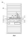
- FIG. 9shows an example rack server system incorporating a side-mounted, rack-level, scalable and modular power infrastructure, according to aspects of the present disclosure.
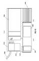
- FIG. 10shows an example side-mounted, rack-level, scalable and modular power infrastructure, according to aspects of the present disclosure.
- an information handling systemmay include any instrumentality or aggregate of instrumentalities operable to compute, classify, process, transmit, receive, retrieve, originate, switch, store, display, manifest, detect, record, reproduce, handle, or utilize any form of information, intelligence, or data for business, scientific, control, or other purposes.
- an information handling systemmay be a personal computer, a network storage device, or any other suitable device and may vary in size, shape, performance, functionality, and price.
- the information handling systemmay include random access memory (RAM), one or more processing resources such as a central processing unit (CPU) or hardware or software control logic, ROM, and/or other types of nonvolatile memory.
- Additional components of the information handling systemmay include one or more disk drives, one or more network ports for communication with external devices as well as various input and output (I/O) devices, such as a keyboard, a mouse, and a video display.
- the information handling systemmay also include one or more buses operable to transmit communications between the various hardware components.
- FIG. 1Shown in FIG. 1 is an example rack-level, scalable and modular power infrastructure 100 , in accordance with aspects of the present disclosure.
- the power infrastructure 100may be used to power servers in any rack/server environment, such as a data center, or in other server environments, as would be appreciated by one of ordinary skill in the art in view of this disclosure.
- the power system 100may receive AC power 102 from a power source.
- AC power 102may be from a common public power grid at a data center site.
- the power infrastructure 100is advantageous because it may be modular, scalable, and may accept various types of input AC power.
- the AC power 102may be received at a power distribution unit (PDU) 104 .
- the PDU 104may include multiple, single-phase commodity power supply units (PSUs), as well as a phase-balancing and distribution configuration that balances power consumption across the power phases of the AC power 102 .
- the PDU 104may output DC power to a common rail, such as busbar 106 , which may be kept at a common 12 volt potential.
- the PDU 104may be modular and scalable according to the amount of power required by the servers.
- the PDU 104may be cross-cabled with a second PDU to provide redundant AC input.
- the redundant AC inputmay provide an alternate source of AC input power, such that sufficient DC power can be provided to the rack server system should one AC input power source fail.
- the PSUsmay be added or removed depending on the power required by the load.
- Busbar 106may be coupled to server components, such as servers 108 a - n , and power infrastructure components, such as PDU 104 , Battery back-up unit (BBU) 110 , and DC/AC inverter 112 .
- Busbar 106may be connected via cables to servers 108 a - n , and may supply the servers 108 a - n with the 12 V DC power supply.
- servers 108 a - nmay include DC/DC power supply units instead of AC/DC power supply units common in typical rack servers, or may accept 12 V DC power directly from the 12 V common rail. This may decrease the size, weight, and heating requirements of a typical rack-mount server.
- a BBU 110may charge from busbar 106 when AC power 102 is provided, and discharge to busbar 106 when AC power 102 is lost.
- a BBUmay also be included inside the PDU 104 within a form-factor chassis similar to the chassis of a commodity PSU.
- the entire AC power feedmay be conditioned using large, expensive batteries to provide an uninterruptable power system (UPS) to all racks/servers within the data center.
- UPSuninterruptable power system
- the input powermay be fed directly to the racks and conditioned at the rack-level, and the entire AC power feed may not need to be uninterruptable. This may reduce the need for an external UPS, reduce the cost of powering the data center, and improve power efficiency.
- the power infrastructure 100may also include AC power outlets, which may be useful for rack operation and maintenance.
- a DC/AC inverter 112may be coupled to the busbar 106 .
- the DC/AC inverter 112may receive the common 12 V power from the busbar 106 and output AC power via common three-prong electrical connections, for example.
- AC power outletsmay also be included within the PDU 104 , as will be discussed below.
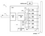
- FIG. 2shows a functional diagram of an example PDU 200 , in accordance with aspects of the present disclosure.
- the PDU 200may be used in a power infrastructure similar to power infrastructure 100 from FIG. 1 , with the PDU 200 receiving AC power 250 and outputting DC power to busbar 252 .
- PDU 200may comprise a rack-mountable chassis in which the power elements of the PDU 200 are disposed.
- the PDU 200may receive AC power 250 at power cable interface box (PCIB) 202 .
- PCIBpower cable interface box
- the PCIB 202may include modular components which allowing the PCIB 202 to accept multiple types of AC power without rewiring by an electrician.
- These multiple type of AC powermay include single-phase, three-phase Delta, three-phase Wye, interruptible, and noninterruptible, and may comprise numerous voltages levels, including 110V, 208V, 220V, 230V, 240V, and 277V.
- AC power 250 received at the PCIB 202may be connected to a distribution element 204 .
- the distribution element 204may represent a wiring scheme whereby phase-balanced power is distributed to power elements disposed within the PDU 200 .
- distribution element 204may be coupled to PSUs 206 a - f via connectors 212 - 218 , 252 , and 254 , respectively.
- Connectors 212 - 218 , 252 , and 254may carry phase-balanced AC power to commodity PSUs 206 a - f , which may then output DC power.
- a three-phase input AC powermay be balanced across the PSUs.
- each phase of AC power 102may be balanced across two PSUs, so that no phase is loaded with more PSUs than any other phase.
- the distribution element 204may also provide AC power outlets at element 210 via cable 224 .
- the PSUs 206 a - fmay comprise commodity PSUs installed into appropriately sized slots within the PDU 200 .
- the PSUs 206 a - fmay couple with and output power through connectors 220 disposed within the PDU 104 .
- the connectors 220may comprise card slots or other form-factor connectors with pre-defined pin configurations.
- PSUs 206 a - fmay couple with connectors 220 .
- the connectorsmay comprise ATX form factor connectors, or other commodity connection types that would be appreciated by one of ordinary skill in view of this disclosure.
- the PSUs 206 a - fmay receive control signals from a power infrastructure controller 222 through the connectors.
- the power infrastructure controller 222may also send control signals to other power elements, as will be described below.
- FIG. 3illustrates an example wiring diagram of PDU 200 , as represented, in part, by distribution element 204 in FIG. 2 .
- the wiring diagramis show relative to PDU 200 , the wiring diagram may be used in other PDUs, as would be appreciated by one of ordinary skill in view of this disclosure.
- AC power 250may be received via a plurality of wires at PCIB 202 , represented by the box around elements 302 , 306 , and 308 .
- the wires received from AC power 250may differ according to the type of AC power 250 .
- the wiresmay comprise three live wires corresponding to the three phases of the power supply, as well as a neutral wire (N) and a ground wire (G).
- the AC power 250may be coupled to the PCIB via a first terminal 302 . Following the first terminal 302 , some or all of the wire may be input into a wiring block 308 , which may be coupled to a second terminal 306 . As can be seen, the wiring block 308 may receive three live wires, as well as the neutral wire from the terminal 302 .
- the ground wiremay be coupled to either Earth ground or electrical ground after terminal 302 .
- the wiresmay be output from the wiring block 308 to the second terminal 306 .
- the wiring block 308may arrange the wires received from terminal 302 into a pre-determined wiring arrangement at second terminal 306 , which corresponds to the wiring arrangement of terminal 310 .
- the wiring block 308may comprise a printed circuit board (PCB) designed for a particular input power type, and interchangeable within the PCIB 202 depending on the type of input power 250 .
- a wiring blockmay be dedicated to single-phase, three-phase Delta, or three-phase Wye power. By swapping the wiring block 308 , the PDU can be configured to accommodate a variety of different input AC power types without an extensive rewiring.
- the wiring block 310may arrange the wires from the AC power into a pre-determined configuration.
- the pre-determined configurationmay correspond to the ports of terminal 310 .
- the terminal 310may accept wires in a common arrangement for all AC input types.
- wiring block 310may comprise a PCB which arranges the input AC wires from within the PCIB 202 to correspond to the wiring arrangement of the terminal 310 .
- Example wiring blocksare described below in FIG. 5 b.
- some of the wires output from the terminal 310may be fed into a breaker 304 .
- the breaker 304may comprise circuit breakers well known in the art, and the live wires may each be connected to an individual breaker to protect against power surges.
- each of the wires output from terminal 310may be coupled individually to a dedicated cable, such as wireways 352 - 362 .
- the wireways 352 - 362may be connected in a staggered configuration with outlets 212 - 218 as well as outlets 252 and 254 .
- outlet 212may be coupled to wireways 354 and 362
- outlet 214may be coupled to wireways 356 and 360 .
- each of the outlets 212 - 218 as well as 252 and 254may be coupled to a unique combination of two dedicated wireways.
- the staggered configurationis designed such that each wireway 352 - 362 is connected to only two outlets 212 - 218 , 252 , and 254 , and may therefore each be connected to two PSUs.
- each phase of input AC power 250through arranging the AC power wires at the wiring block 308 and terminal 310 , and staggering the outlets 212 - 218 , 252 , and 254 across the dedicated wireways 352 - 362 , may see a generally equal amount of power draw from the load.
- the input AC powermay be connected to relays 312 , 314 , and 316 , which are coupled to switched AC outlets 210 .
- each of the relays 312 , 314 , and 316may be coupled to two different wires from terminal 310 .
- the relaysmay include mechanical or electrical switches located locally at the rack, allowing some or all of the outlets 210 to be turned on and off.
- the relaysmay be triggered from a remote source, allowing an administrator, for example, to power up secondary server gear without being physically located at a data center site.
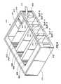
- FIG. 4illustrates an isometric view of an example PDU 400 deployed in a rack-mountable chassis 450 , with a top section removed to better illustrate the internal configuration.
- PDU 400may include a similar wiring diagram to the wiring diagram illustrated in FIG. 3 .
- AC power 452may be received at the PDU 400 through PCIB 454 .
- the PDU 400may include breakers 470 , which may in some embodiments be accessible from the from of the PDU 400 .
- PCIB 454may be detachable, and may connect with the PDU 400 through a detachable interface 490 , as will be described below with respect to FIG. 5 a .
- the PCIB 454may connect with a terminal 456 integrated into the PDU 400 via the detachable interface 490 .
- the AC power 452may then be phase balanced and distributed to connections 458 - 468 and switchable connections (not shown), as described above with respect to FIG. 3 .
- each of the connections 458 - 468may comprise common three-prong power cables that are either integrated into the PDU 400 or are connected at one end to the outlets integrated into the PDU 400 and at the other end to an outlet disposed on a commodity PSU installed within one of Slots 1 - 6 .
- the slots 1 - 6may be sized to accommodate commodity PSUs.
- PSUsdepending on the form factor of the PSUs, other numbers of PSUs, such as 9 or 12, can be incorporated into the PDU to achieve a higher power total.
- the distribution wiringwould need to be modified such that each of the phases supplies the same number of PSUs.
- PSU numbers in a multiple of threeis preferred to maintain balance.
- Each of Slots 1 - 6may be similarly sized, elongated cuboid openings and may accept a similarly sized form factor, commodity PSU.
- PSUsmay be inserted through the front opening, adjacent to the connectors 458 - 468 , and pushed into the PSU.
- a connector at the back of the PSUmay engage with a connector disposed at the back of each slot, Slot 1 - 6 , opposite the front of the PDU.
- the connectors 402 - 412may comprise card slots that engage with a form-factor card protruding from the back of each PSU (not shown).
- Each form factor cardmay have the same pin-out configuration, receiving control signal from a power infrastructure controller, such as power infrastructure controller 222 , and outputting power through the same pins.
- the connectors 402 - 412may comprise other connectors well known in the art, such as ATX form factor connectors, as would be appreciated by one of ordinary skill in the art in view of this disclosure.
- the connectors 402 - 412may be coupled to a busbar (not shown), such as busbar 106 from FIG. 1 , through which the PSU may supply DC power to servers within a rack structure.
- the PDU 400may also comprise a power infrastructure controller 470 integrated into the PDU structure and communicating at least with the PSUs coupled to the PDU through connectors 402 - 412 .
- FIG. 5 aillustrates an example detachable PCIB 500 , similar to the PCIB 454 in FIG. 4 , which incorporates a detachable interface 502 and allows for insertion/coupling and removal/decoupling of power from a PDU.
- the PCIB 500when the PCIB 500 is inserted into the PDU, the PCIB 500 may be secured to the PDU body to maintain ground contact.
- the AC power configuration in current data centersvaries based several different parameters, including current rating, such as 20, 30, or 50 amps; phase number, such as single or 3 phase; cable length; voltage, such as 208V, 220V, 240V, or 277V; and configuration, such as Wye or Delta.
- the PDUcan be manufactured as a modular unit with a pre-determined interface to the PCIB, with the interface being common to all PCIBs.
- the PCIBcan then be coupled to power sources of any type—including the power types mentioned above as well as High Voltage DC—and connected to the common interface. This allows the PDU to accept any power type without the PDU having to be reconfigured or rewired. Rather, the configuration is limited to, for example, the wiring block in the PCIB.
- the detachable PCIB 500may comprise a rectangular body section coupled to the AC power 550 .
- the detachable PCIB 500may be coupled to AC power 550 via terminal 504 in the body section before the detachable PCIB 500 is inserted into a PDU.
- the detachable PCIB 500includes terminals 504 and 506 .
- a detachable PCIBmay include elements similar to the terminals shown in FIG. 3 .
- the detachable PCIB 500may include a wiring block 520 , positioned between terminal 504 and terminal 506 .
- the wiring block 520may comprise a PCB and may arrange the power from AC power 550 into a pre-determined output configuration corresponding to the detachable interface, similar to wiring block 308 described above.
- the detachable interfacemay, for example, include a pre-determined pin configuration, and the wires from the AC power 550 may be arranged to correspond to the pre-determined pin configuration of the detachable interface.
- the type of wires and power coupled to each pinmay be common across all types of AC power, such that the detachable PCIB 500 can be coupled to a PDU through, for example, an integrated connector 560 , and the PDU would accept AC power from the detachable PCIB 500 without having to be modified at all.
- a six pin detachable interface 502may be used to connect any single-phase, and various three-phase AC power feeds to the PDU via an integrated connector 560 with the power earth or power ground, directly connected to the PCIB 500 .
- the six-pin interface 502 and the integrated connector 560may include complementary pin configuration, ensuring that the correct wires from the AC power are connected to the correct terminal in the PDU.
- Each of the pins of the six-pin interfacemay be used regardless of the input-power type.
- an eight-pin interfacemay be utilized, consisting of the six-pins described above as well as a PG pin and an input voltage identification pin that indicates, for example, when an input voltage is 277V.
- the PG pinmay connect the power or earth ground through the PDU, while the input voltage identification pin may be used to differentiate a high input AC voltage, such as 277V, from other lower input AC voltages.
- the PDUmay respond to a signal on the input voltage identification pin, indicating for example a 277V input voltage, by automatically disabling at least one power element in the PDU.
- the PDUmay disable switchable outlets at the PDU to protect any device connected to the switchable outlets from being exposed to the high voltage, while still proving power to PSUs disposed within the PDU.
- each pin of the interface 502is not required to be in use for all power types. Rather, for single phase power types, for example, some of the pins may not be used.
- a detachable PCIBsuch as PCIB 500 in FIG. 5 a may allow for a modular power infrastructure design that couples to an AC power source through a common interface on the detachable PCIB instead of having to be rewired to accommodate different power types.
- the detachable PCIBsmay be Underwriters Laboratories (UL) approved, meaning that the AC power can be coupled to the detachable PCIB on site, and then coupled to the power infrastructure without requiring an electrician.
- ULUnderwriters Laboratories
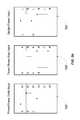
- FIG. 5 bshows example wiring block configurations for three-phase Delta input power, three-phase Wye input power, and single phase input power.
- each of the example wiring blocksarranges the input power into a universal six wire output that may interchangeably correspond, for example, to the pre-determined wiring arrangement at a PDU.
- the three-phase Delta power inputfor example, may include three input wires, A, B, and C.
- the wiring blockmay arrange the wires such that six wires—A 1 , B 2 , B 1 , C 2 , C 1 , A 2 —are output from the wiring block.
- the three-phase Wye power inputmay include four wires, A, B, C, and N and the wiring block may be arranged to provide a six wire output—A, N, B, N, C, N.
- the single phase power inputfor example, may include two wires, L and N, and the wiring block may be arranged to provide a six wire output—L, N, L, N, L, N.
- the wiring blockmay outputs a six wire arrangement.
- Each wiring blockmay be used interchangeably in a PCIB, for example, with the correct wiring block being selected for the type of input power.
- the wiring block outputmay then be coupled to a terminal within the PCIB which corresponds to an input terminal at the PDU.
- the configurationmay be advantageous because configuring the input power may be accomplished apart from the design of a PDU, simplifying the design and allowing for modularization.
- a BBUsuch as BBU 110
- BBU 110may also be included within the power infrastructure, receiving DC power from a busbar to charge the internal batteries, and outputting DC power to the busbar when the AC power source fails or is lost.
- FIG. 6illustrates an example BBU system 600 which may be sized similarly to a rack server, and mountable within a rack using tabs 618 , positioned at the front to the BBU system 600 .
- a BBU systemmay be disposed within the PDU.
- the BBU system 600may include at least one battery 610 within a battery drawer 650 .
- the battery 610may comprise multiple types, including Lithium Polymer and valve-regulated lead-acid (VRLA), and the BBU system 600 may receive and store power at multiple voltage levels, including 18V, 48V, and 240V-400V DC.
- the BBU system 600may comprise redundant batteries.
- the battery drawer 650may be open at the front of the BBU system 600 , allowing the batteries 610 to be easily accessed and interchanged for maintenance and other operational conditions.
- the battery 610may be hot-swappable.
- the battery 610may be electrically coupled to power modules 602 via connector 612 .
- the power modules 602may comprise multiple power modules, for example six or eight power modules, depending on the amount of power input to the BBU system 600 .
- the power modules 602may be coupled to a DC busbar, such as busbar 106 from FIG. 1 , via busbar connector 604 , and also may be coupled to a ground return via busbar connection 606 .
- the power modules 602may act as a power conversion and regulation device which converts generally variable battery voltage to a regulated voltage on the 12 V common rail in discharge mode, and vice versa in charge mode.
- the power modules 602may also be configured to accommodate variable DC inputs, such as The power modules 602 may be in parallel operation with current or load sharing.
- the power modules 602may cause the battery 610 to either be charged by the input DC power from busbar connector 604 , or discharge DC power to a busbar through busbar connector 604 .
- the BBU system 600may receive at a power module controller 614 a control signal through a PDU interface 608 .
- the control signalmay come from a power infrastructure controller, such as power infrastructure controller 222 , and may indicate, for example, that the PDU has lost AC power.
- the control signalmay comprise, for example, a simple network management protocol (SNMP) signal.
- the power module controller 614may respond to the control signal by issuing a control command to the power modules 602 .
- the power modules 602may cause the BBU to be in a charge mode, where the DC power from the DC busbar is used to charge the battery 610 . If the PDU is not receiving power, for example, the power modules 602 may cause the BBU to be in a discharge mode, where the battery 610 outputs power to the DC busbar.
- the BBU system 600may further include an emergency power off 616 , which functions as a kill switch to the BBU 110 .
- the BBU system 600may further communicate bi-directionally with a power controller, such as power infrastructure controller 222 , to allow for power capping during battery usage as well as to allow the server system, or an administrator accessing the server system, to have information about the BBU system 600 .
- the informationmay include information used for power management, including, but not limited to, battery state, battery health, battery capacity, and battery temperature.
- the BBU system 600may communicate with a power controller to allow for both passive and active power sharing between the power infrastructure and the BBU system 600 .
- a power controllermay communicate with the BBU system 600 to vary the amount of power used by the BBU system 600 to charge battery 610 .
- BBU system 600is shown with busbar connections 604 and 606 , receiving for example a 12 V DC input power, other configurations are possible.
- BBU system 600may receiver power from a PDU through a cable instead of a busbar.
- the BBU system 600may receiver a higher voltage level DC power, such as 48 V or up to 400V, through an additional connector (not shown).
- a higher voltage level DC powersuch as 48 V or up to 400V
- a power infrastructuresuch as the power infrastructure in FIG. 1
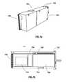
- FIG. 7 ashows an example BBU system 700 incorporated into a form-factor chassis 704 similar to a commodity PSU described above.
- chassis 704may be sized to fit within a commodity power supply unit (PSU) slot in a power distribution unit (PDU), such as Slot 1 in FIG. 4 , instead of a commodity PSU.
- PSUcommodity power supply unit
- PDUpower distribution unit
- BBU system 700includes an example form-factor connector, connector card 706 , protruding from the back of the chassis 704 .
- This connector card 706may comprise a pre-determined pinout configuration that matches the pinout configuration of a similarly-sized commodity PSU, so the BBU system 700 is swappable with a commodity PSU within the PDU.
- the connector card 706may coupled to a card connector within a PDU, such as connectors 402 - 412 in FIG. 4 .
- the chassis 700may include form-factor alignment and latching mechanisms 702 similar to a commodity PSU.
- FIG. 7 bshows an example configuration of a BBU system 700 with one side of the chassis 704 removed.
- the BBU system 700comprises a battery 708 and a power module 710 , with the battery 708 coupled to the power module 710 via cable 712 .
- the BBU system 700may further include a power module controller 714 coupled to the power module 710 .
- control signals and powermay be received through pre-determined pins on the card connector 706 .
- the module controller 714may receive the control signals can cause the power modules to charge the battery 708 with the received DC power or to output power from the battery 708 through the card 706 .
- FIG. 8illustrates an example rack server system incorporating aspects of an example modular and scalable power distribution system, according to aspects of the present invention.
- the rack server systemincludes a rack 800 , populated with server systems 802 , a PDU 804 , a busbar 806 , a DC/AC inverter 808 , and a BBU system 810 .
- the PDU 804may receive AC input power 812 via detachable PCIB 814 .
- Multiple single-phase, commodity PSUs, such as PSU 816 and 820may be installed into slots within PDU 804 , receive phase-balanced AC power from the PDU over, for example, connectors 818 , and output DC power to busbar 806 via cable 852 .
- the PDU 804may for example, further comprise a BBU system deployed within the PDU 804 instead of PSU 820 , sized similarly to the single-phase, commodity PSU 820 , and which receives power from and outputs power to the busbar 806 .
- a BBU systemdeployed within the PDU 804 instead of PSU 820 , sized similarly to the single-phase, commodity PSU 820 , and which receives power from and outputs power to the busbar 806 .
- a BBU system 810 and a DC/AC inverter 808may also be coupled to the busbar 806 .
- the BBU system 810may be similar to the BBU system 600 in FIG. 6 , and may comprise a battery slot 822 , and an emergency power-off 824 .
- the BBU system 810may also include power modules (not shown) that cause the BBU system 810 to either receive power from busbar 806 or output power to busbar 806 via cable 850 .
- DC/AC inverter 808may receive DC power from the busbar 806 via cable 840 .
- the DC/AC inverter 808may provide AC output power at common three-prong power outlets, allowing common networking equipment to be powered without an additional AC input line and in cases when the AC input fails or is lost.
- Each of the servers 802may receive DC power from a PDU 804 or BBU system 810 via busbar 806 .
- Each of the serversmay accept external 12 V DC power, instead of AC/DC power supplies common in most server applications.
- BBU system 810may output power onto the busbar 806 , powering servers 802 and inverter 808 until AC input power 812 can be restored.
- FIG illustrating system 800is simplified. In a physical implementation, additional connections would be included to each of the servers, and such connections may include additional power equipment, such as wires, cables, busbars.
- each systemmay have multiple 12 V power domains, with different 12 V busbars, that can be either stand-alone or interconnected.
- a scalable and modular power infrastructure similar to the infrastructure shown in FIGS. 1 and 8may be deployed outside of used rack space.
- space within rack 800is used for the power equipment, decreasing the server capacity.
- the power infrastructuremay be deployed outside of usable server space within the rack.
- FIG. 9shows an example unpopulated rack 900 .
- the rackfor example, may include multiple compartments 904 , each of which may be fully populated with servers.
- Side-car chassis 902 containing modular and scalable power infrastructuremay be mounted to the side of the rack 900 , preserving usable rack space.
- FIG. 10shows an example configuration of a modular and scalable power infrastructure 1000 deployed in a side-car chassis 1050 .
- the power infrastructure 1000may receive AC input power 1002 at a PCIB 1012 .
- the PCIB 1002may include a modular wiring block, such as wiring block 308 above, or may be detachable, similar to PCIB 500 from FIG. 5 a .
- power infrastructure 1000may comprise phase-balancing and distribution circuitry similar to the wiring diagram in FIG. 3 .
- PSUs 1006may be installed within the side-car chassis 1050 through an opening or power supply unit slot at the front of the side-car chassis 1050 , and may receive pluggable AC power.
- Each of the PSUs 1006may be coupled to a busbar 1010 , via form-factor connections 1052 within the side-car chassis 1050 .
- the number of PSUs, and total output powermay be scalable by inserting additional PSUs within the infrastructure 1000 .
- the infrastructuremay be modular by accepting commodity PSUs via the form-factor connections 1052 .
- the busbar 1010may be partially disposed within the chassis 1050 and may provide power to servers within a rack.
- the power infrastructure 1000may include a BBU disposed within the chassis 1050 , similar to the BBUs described above.
- the BBUmay include a hot-swappable battery 1004 , which may be installed through the front of the side-car chassis 1050 , and connect with connector 1054 .
- the BBUmay also include power modules and a power module controller 1008 , and may cause the battery 1004 to either charge from the busbar 1010 or discharge power to the busbar 1010 .
- the power infrastructure 1000may include AC power outlets 1014 to power equipment for the rack/server system.
Landscapes
- Engineering & Computer Science (AREA)
- Theoretical Computer Science (AREA)
- Power Engineering (AREA)
- Physics & Mathematics (AREA)
- General Engineering & Computer Science (AREA)
- General Physics & Mathematics (AREA)
- Business, Economics & Management (AREA)
- Emergency Management (AREA)
- Charge And Discharge Circuits For Batteries Or The Like (AREA)
Abstract
Description
Claims (20)
Priority Applications (2)
| Application Number | Priority Date | Filing Date | Title |
|---|---|---|---|
| US13/364,145US8972752B2 (en) | 2012-02-01 | 2012-02-01 | System and method for providing modular and scalable power infrastructure outside of usable it space |
| US14/602,597US9270089B2 (en) | 2012-02-01 | 2015-01-22 | System and method for providing modular and scalable power infrastructure outside of usable IT space |
Applications Claiming Priority (1)
| Application Number | Priority Date | Filing Date | Title |
|---|---|---|---|
| US13/364,145US8972752B2 (en) | 2012-02-01 | 2012-02-01 | System and method for providing modular and scalable power infrastructure outside of usable it space |
Related Child Applications (1)
| Application Number | Title | Priority Date | Filing Date |
|---|---|---|---|
| US14/602,597ContinuationUS9270089B2 (en) | 2012-02-01 | 2015-01-22 | System and method for providing modular and scalable power infrastructure outside of usable IT space |
Publications (2)
| Publication Number | Publication Date |
|---|---|
| US20130198534A1 US20130198534A1 (en) | 2013-08-01 |
| US8972752B2true US8972752B2 (en) | 2015-03-03 |
Family
ID=48871376
Family Applications (2)
| Application Number | Title | Priority Date | Filing Date |
|---|---|---|---|
| US13/364,145Active2033-04-22US8972752B2 (en) | 2012-02-01 | 2012-02-01 | System and method for providing modular and scalable power infrastructure outside of usable it space |
| US14/602,597ActiveUS9270089B2 (en) | 2012-02-01 | 2015-01-22 | System and method for providing modular and scalable power infrastructure outside of usable IT space |
Family Applications After (1)
| Application Number | Title | Priority Date | Filing Date |
|---|---|---|---|
| US14/602,597ActiveUS9270089B2 (en) | 2012-02-01 | 2015-01-22 | System and method for providing modular and scalable power infrastructure outside of usable IT space |
Country Status (1)
| Country | Link |
|---|---|
| US (2) | US8972752B2 (en) |
Cited By (5)
| Publication number | Priority date | Publication date | Assignee | Title |
|---|---|---|---|---|
| US20130198533A1 (en)* | 2012-02-01 | 2013-08-01 | Dell Products L.P. | Systems and methods for providing scalable uninterruptable dc power to a rack-level power infrastructure |
| US20140192456A1 (en)* | 2012-02-01 | 2014-07-10 | Dell Products L.P. | Systems and methods for coupling ac power to a rack-level power infrastructure |
| US20150143140A1 (en)* | 2012-02-01 | 2015-05-21 | Edmond I. Bailey | System and method for providing modular and scalable power infrastructure outside of usable it space |
| US20160091961A1 (en)* | 2014-09-30 | 2016-03-31 | Inventec (Pudong) Technology Corporation | Rack server system |
| US20220271513A1 (en)* | 2021-02-23 | 2022-08-25 | Cisco Technology, Inc. | Modular and pluggable pdu to power tray/shelf device |
Families Citing this family (15)
| Publication number | Priority date | Publication date | Assignee | Title |
|---|---|---|---|---|
| TWI453577B (en)* | 2012-03-21 | 2014-09-21 | Hon Hai Prec Ind Co Ltd | Power source equipment for cabinet for server |
| US9804654B2 (en) | 2012-12-05 | 2017-10-31 | Google Inc. | Backup power architecture for rack system |
| US9733682B2 (en)* | 2013-12-19 | 2017-08-15 | VCE IP Holding Company LLC | Scalable computing rack power distribution unit |
| US9474181B2 (en)* | 2013-12-23 | 2016-10-18 | Dell Products, L.P. | Combined power and management module for use in a rack-configured information handling system |
| US9232678B2 (en)* | 2013-12-30 | 2016-01-05 | Dell Products L.P. | Modular, scalable, expandable, rack-based information handling system |
| CN104598004A (en)* | 2015-01-13 | 2015-05-06 | 浪潮电子信息产业股份有限公司 | RACK cabinet copper bar power supply method meeting higher node deployment density |
| CN105515122A (en)* | 2016-01-27 | 2016-04-20 | 国网安徽省电力公司芜湖县供电公司 | Green energy emergency power system |
| CN107664752A (en)* | 2017-09-07 | 2018-02-06 | 郑州云海信息技术有限公司 | A kind of battery pack method of calibration, apparatus and system |
| US10524377B2 (en) | 2018-01-31 | 2019-12-31 | Eaton Intelligent Power Limited | Power distribution unit with interior busbars |
| US12108559B2 (en)* | 2018-12-21 | 2024-10-01 | Acleap Power Inc. | Modular edge power systems |
| WO2021163205A1 (en)* | 2020-02-11 | 2021-08-19 | Schneider Electric It Corporation | Base electrical module for modular data center |
| US11770377B1 (en)* | 2020-06-29 | 2023-09-26 | Cyral Inc. | Non-in line data monitoring and security services |
| US11910575B2 (en)* | 2021-09-02 | 2024-02-20 | Baidu Usa Llc | Rack systems and packaging for servers |
| CN114285138B (en)* | 2021-12-31 | 2022-11-18 | 深圳市英威腾电源有限公司 | Bus voltage-sharing balance control device and three-phase high-frequency UPS |
| US20250220844A1 (en)* | 2023-12-27 | 2025-07-03 | Dell Products L.P. | Server chassis including an integrated power supply unit |
Citations (3)
| Publication number | Priority date | Publication date | Assignee | Title |
|---|---|---|---|---|
| US20070109736A1 (en)* | 2003-05-16 | 2007-05-17 | Giovanni Coglitore | Computer rack with power distribution system |
| US7379305B2 (en)* | 2004-01-23 | 2008-05-27 | American Power Conversion Corporation | Modular UPS |
| US20110043986A1 (en)* | 2008-04-30 | 2011-02-24 | Conn Kevin D | Power supply assembly for server rack and method for mounting power supply for server rack |
Family Cites Families (1)
| Publication number | Priority date | Publication date | Assignee | Title |
|---|---|---|---|---|
| US8972752B2 (en)* | 2012-02-01 | 2015-03-03 | Dell Products L.P. | System and method for providing modular and scalable power infrastructure outside of usable it space |
- 2012
- 2012-02-01USUS13/364,145patent/US8972752B2/enactiveActive
- 2015
- 2015-01-22USUS14/602,597patent/US9270089B2/enactiveActive
Patent Citations (3)
| Publication number | Priority date | Publication date | Assignee | Title |
|---|---|---|---|---|
| US20070109736A1 (en)* | 2003-05-16 | 2007-05-17 | Giovanni Coglitore | Computer rack with power distribution system |
| US7379305B2 (en)* | 2004-01-23 | 2008-05-27 | American Power Conversion Corporation | Modular UPS |
| US20110043986A1 (en)* | 2008-04-30 | 2011-02-24 | Conn Kevin D | Power supply assembly for server rack and method for mounting power supply for server rack |
Cited By (14)
| Publication number | Priority date | Publication date | Assignee | Title |
|---|---|---|---|---|
| US9270089B2 (en)* | 2012-02-01 | 2016-02-23 | Dell Products L.P. | System and method for providing modular and scalable power infrastructure outside of usable IT space |
| US20130198533A1 (en)* | 2012-02-01 | 2013-08-01 | Dell Products L.P. | Systems and methods for providing scalable uninterruptable dc power to a rack-level power infrastructure |
| US20150143140A1 (en)* | 2012-02-01 | 2015-05-21 | Edmond I. Bailey | System and method for providing modular and scalable power infrastructure outside of usable it space |
| US9141164B2 (en)* | 2012-02-01 | 2015-09-22 | Dell Products L.P. | Systems and methods for providing scalable uninterruptable DC power to a rack-level power infrastructure |
| US9172219B2 (en)* | 2012-02-01 | 2015-10-27 | Dell Products L.P. | Systems and methods for coupling AC power to a rack-level power infrastructure |
| US20150357865A1 (en)* | 2012-02-01 | 2015-12-10 | Dell Products L.P. | Systems and methods for providing scalable uninterruptable dc power to a rack-level power infrastructure |
| US9389666B2 (en)* | 2012-02-01 | 2016-07-12 | Dell Products L.P. | Systems and methods for providing scalable uninterruptable DC power to a rack-level power infrastructure |
| US9661777B2 (en) | 2012-02-01 | 2017-05-23 | Dell Products L.P. | Systems and methods for coupling AC power to a rack-level power infrastructure |
| US20140192456A1 (en)* | 2012-02-01 | 2014-07-10 | Dell Products L.P. | Systems and methods for coupling ac power to a rack-level power infrastructure |
| US9438012B2 (en) | 2012-02-01 | 2016-09-06 | Dell Products L.P. | Systems and methods for coupling AC power to a rack-level power infrastructure |
| US9436247B2 (en)* | 2014-09-30 | 2016-09-06 | Inventec (Pudong) Technology Corporation | Rack server system |
| US20160091961A1 (en)* | 2014-09-30 | 2016-03-31 | Inventec (Pudong) Technology Corporation | Rack server system |
| US20220271513A1 (en)* | 2021-02-23 | 2022-08-25 | Cisco Technology, Inc. | Modular and pluggable pdu to power tray/shelf device |
| US11910554B2 (en)* | 2021-02-23 | 2024-02-20 | Cisco Technology, Inc. | Modular and pluggable PDU to power tray/shelf device |
Also Published As
| Publication number | Publication date |
|---|---|
| US20130198534A1 (en) | 2013-08-01 |
| US9270089B2 (en) | 2016-02-23 |
| US20150143140A1 (en) | 2015-05-21 |
Similar Documents
| Publication | Publication Date | Title |
|---|---|---|
| US9661777B2 (en) | Systems and methods for coupling AC power to a rack-level power infrastructure | |
| US9642282B2 (en) | Rack-level scalable and modular power infrastructure | |
| US9270089B2 (en) | System and method for providing modular and scalable power infrastructure outside of usable IT space | |
| US9991740B2 (en) | Form factor swappable DC battery back-up | |
| US9389666B2 (en) | Systems and methods for providing scalable uninterruptable DC power to a rack-level power infrastructure | |
| US7215535B2 (en) | Modular power distribution system for use in computer equipment racks | |
| US9733682B2 (en) | Scalable computing rack power distribution unit | |
| KR102092103B1 (en) | System and method for rack mountable modular dc power unit | |
| US8395900B2 (en) | Power routing device for expansion slot of computer system | |
| AU2013234884B2 (en) | Power usage monitoring of power feed circuits using power distribution units | |
| US11316365B2 (en) | Modular uninterruptible power supply and power distribution system | |
| US8836175B1 (en) | Power distribution system for rack-mounted equipment | |
| US11139530B2 (en) | Space saving, modular, hot-pluggable power modules | |
| HK1221292B (en) | System and method for rack mountable modular dc power unit |
Legal Events
| Date | Code | Title | Description |
|---|---|---|---|
| AS | Assignment | Owner name:DELL PRODUCTS L.P., TEXAS Free format text:ASSIGNMENT OF ASSIGNORS INTEREST;ASSIGNORS:BAILEY, EDMOND I.;VIVIO, JOSEPH A.;PIKE, JIMMY D.;REEL/FRAME:027636/0352 Effective date:20120130 | |
| AS | Assignment | Owner name:BANK OF NEW YORK MELLON TRUST COMPANY, N.A., AS FIRST LIEN COLLATERAL AGENT, TEXAS Free format text:PATENT SECURITY AGREEMENT (NOTES);ASSIGNORS:APPASSURE SOFTWARE, INC.;ASAP SOFTWARE EXPRESS, INC.;BOOMI, INC.;AND OTHERS;REEL/FRAME:031897/0348 Effective date:20131029 Owner name:BANK OF AMERICA, N.A., AS ADMINISTRATIVE AGENT, TEXAS Free format text:PATENT SECURITY AGREEMENT (ABL);ASSIGNORS:DELL INC.;APPASSURE SOFTWARE, INC.;ASAP SOFTWARE EXPRESS, INC.;AND OTHERS;REEL/FRAME:031898/0001 Effective date:20131029 Owner name:BANK OF AMERICA, N.A., AS COLLATERAL AGENT, NORTH CAROLINA Free format text:PATENT SECURITY AGREEMENT (TERM LOAN);ASSIGNORS:DELL INC.;APPASSURE SOFTWARE, INC.;ASAP SOFTWARE EXPRESS, INC.;AND OTHERS;REEL/FRAME:031899/0261 Effective date:20131029 Owner name:BANK OF AMERICA, N.A., AS COLLATERAL AGENT, NORTH Free format text:PATENT SECURITY AGREEMENT (TERM LOAN);ASSIGNORS:DELL INC.;APPASSURE SOFTWARE, INC.;ASAP SOFTWARE EXPRESS, INC.;AND OTHERS;REEL/FRAME:031899/0261 Effective date:20131029 Owner name:BANK OF NEW YORK MELLON TRUST COMPANY, N.A., AS FI Free format text:PATENT SECURITY AGREEMENT (NOTES);ASSIGNORS:APPASSURE SOFTWARE, INC.;ASAP SOFTWARE EXPRESS, INC.;BOOMI, INC.;AND OTHERS;REEL/FRAME:031897/0348 Effective date:20131029 Owner name:BANK OF AMERICA, N.A., AS ADMINISTRATIVE AGENT, TE Free format text:PATENT SECURITY AGREEMENT (ABL);ASSIGNORS:DELL INC.;APPASSURE SOFTWARE, INC.;ASAP SOFTWARE EXPRESS, INC.;AND OTHERS;REEL/FRAME:031898/0001 Effective date:20131029 | |
| FEPP | Fee payment procedure | Free format text:PAYOR NUMBER ASSIGNED (ORIGINAL EVENT CODE: ASPN); ENTITY STATUS OF PATENT OWNER: LARGE ENTITY | |
| STCF | Information on status: patent grant | Free format text:PATENTED CASE | |
| AS | Assignment | Owner name:SECUREWORKS, INC., GEORGIA Free format text:RELEASE BY SECURED PARTY;ASSIGNOR:BANK OF AMERICA, N.A., AS ADMINISTRATIVE AGENT;REEL/FRAME:040065/0216 Effective date:20160907 Owner name:CREDANT TECHNOLOGIES, INC., TEXAS Free format text:RELEASE BY SECURED PARTY;ASSIGNOR:BANK OF AMERICA, N.A., AS ADMINISTRATIVE AGENT;REEL/FRAME:040065/0216 Effective date:20160907 Owner name:DELL PRODUCTS L.P., TEXAS Free format text:RELEASE BY SECURED PARTY;ASSIGNOR:BANK OF AMERICA, N.A., AS ADMINISTRATIVE AGENT;REEL/FRAME:040065/0216 Effective date:20160907 Owner name:APPASSURE SOFTWARE, INC., VIRGINIA Free format text:RELEASE BY SECURED PARTY;ASSIGNOR:BANK OF AMERICA, N.A., AS ADMINISTRATIVE AGENT;REEL/FRAME:040065/0216 Effective date:20160907 Owner name:COMPELLANT TECHNOLOGIES, INC., MINNESOTA Free format text:RELEASE BY SECURED PARTY;ASSIGNOR:BANK OF AMERICA, N.A., AS ADMINISTRATIVE AGENT;REEL/FRAME:040065/0216 Effective date:20160907 Owner name:DELL USA L.P., TEXAS Free format text:RELEASE BY SECURED PARTY;ASSIGNOR:BANK OF AMERICA, N.A., AS ADMINISTRATIVE AGENT;REEL/FRAME:040065/0216 Effective date:20160907 Owner name:DELL INC., TEXAS Free format text:RELEASE BY SECURED PARTY;ASSIGNOR:BANK OF AMERICA, N.A., AS ADMINISTRATIVE AGENT;REEL/FRAME:040065/0216 Effective date:20160907 Owner name:DELL SOFTWARE INC., CALIFORNIA Free format text:RELEASE BY SECURED PARTY;ASSIGNOR:BANK OF AMERICA, N.A., AS ADMINISTRATIVE AGENT;REEL/FRAME:040065/0216 Effective date:20160907 Owner name:PEROT SYSTEMS CORPORATION, TEXAS Free format text:RELEASE BY SECURED PARTY;ASSIGNOR:BANK OF AMERICA, N.A., AS ADMINISTRATIVE AGENT;REEL/FRAME:040065/0216 Effective date:20160907 Owner name:ASAP SOFTWARE EXPRESS, INC., ILLINOIS Free format text:RELEASE BY SECURED PARTY;ASSIGNOR:BANK OF AMERICA, N.A., AS ADMINISTRATIVE AGENT;REEL/FRAME:040065/0216 Effective date:20160907 Owner name:FORCE10 NETWORKS, INC., CALIFORNIA Free format text:RELEASE BY SECURED PARTY;ASSIGNOR:BANK OF AMERICA, N.A., AS ADMINISTRATIVE AGENT;REEL/FRAME:040065/0216 Effective date:20160907 Owner name:WYSE TECHNOLOGY L.L.C., CALIFORNIA Free format text:RELEASE BY SECURED PARTY;ASSIGNOR:BANK OF AMERICA, N.A., AS ADMINISTRATIVE AGENT;REEL/FRAME:040065/0216 Effective date:20160907 Owner name:DELL MARKETING L.P., TEXAS Free format text:RELEASE BY SECURED PARTY;ASSIGNOR:BANK OF AMERICA, N.A., AS ADMINISTRATIVE AGENT;REEL/FRAME:040065/0216 Effective date:20160907 | |
| AS | Assignment | Owner name:WYSE TECHNOLOGY L.L.C., CALIFORNIA Free format text:RELEASE BY SECURED PARTY;ASSIGNOR:BANK OF AMERICA, N.A., AS COLLATERAL AGENT;REEL/FRAME:040040/0001 Effective date:20160907 Owner name:DELL INC., TEXAS Free format text:RELEASE BY SECURED PARTY;ASSIGNOR:BANK OF AMERICA, N.A., AS COLLATERAL AGENT;REEL/FRAME:040040/0001 Effective date:20160907 Owner name:PEROT SYSTEMS CORPORATION, TEXAS Free format text:RELEASE BY SECURED PARTY;ASSIGNOR:BANK OF AMERICA, N.A., AS COLLATERAL AGENT;REEL/FRAME:040040/0001 Effective date:20160907 Owner name:DELL SOFTWARE INC., CALIFORNIA Free format text:RELEASE BY SECURED PARTY;ASSIGNOR:BANK OF AMERICA, N.A., AS COLLATERAL AGENT;REEL/FRAME:040040/0001 Effective date:20160907 Owner name:FORCE10 NETWORKS, INC., CALIFORNIA Free format text:RELEASE BY SECURED PARTY;ASSIGNOR:BANK OF AMERICA, N.A., AS COLLATERAL AGENT;REEL/FRAME:040040/0001 Effective date:20160907 Owner name:APPASSURE SOFTWARE, INC., VIRGINIA Free format text:RELEASE BY SECURED PARTY;ASSIGNOR:BANK OF AMERICA, N.A., AS COLLATERAL AGENT;REEL/FRAME:040040/0001 Effective date:20160907 Owner name:DELL MARKETING L.P., TEXAS Free format text:RELEASE BY SECURED PARTY;ASSIGNOR:BANK OF AMERICA, N.A., AS COLLATERAL AGENT;REEL/FRAME:040040/0001 Effective date:20160907 Owner name:DELL PRODUCTS L.P., TEXAS Free format text:RELEASE BY SECURED PARTY;ASSIGNOR:BANK OF AMERICA, N.A., AS COLLATERAL AGENT;REEL/FRAME:040040/0001 Effective date:20160907 Owner name:CREDANT TECHNOLOGIES, INC., TEXAS Free format text:RELEASE BY SECURED PARTY;ASSIGNOR:BANK OF AMERICA, N.A., AS COLLATERAL AGENT;REEL/FRAME:040040/0001 Effective date:20160907 Owner name:SECUREWORKS, INC., GEORGIA Free format text:RELEASE BY SECURED PARTY;ASSIGNOR:BANK OF AMERICA, N.A., AS COLLATERAL AGENT;REEL/FRAME:040040/0001 Effective date:20160907 Owner name:ASAP SOFTWARE EXPRESS, INC., ILLINOIS Free format text:RELEASE BY SECURED PARTY;ASSIGNOR:BANK OF AMERICA, N.A., AS COLLATERAL AGENT;REEL/FRAME:040040/0001 Effective date:20160907 Owner name:COMPELLENT TECHNOLOGIES, INC., MINNESOTA Free format text:RELEASE BY SECURED PARTY;ASSIGNOR:BANK OF AMERICA, N.A., AS COLLATERAL AGENT;REEL/FRAME:040040/0001 Effective date:20160907 Owner name:DELL USA L.P., TEXAS Free format text:RELEASE BY SECURED PARTY;ASSIGNOR:BANK OF AMERICA, N.A., AS COLLATERAL AGENT;REEL/FRAME:040040/0001 Effective date:20160907 Owner name:DELL SOFTWARE INC., CALIFORNIA Free format text:RELEASE BY SECURED PARTY;ASSIGNOR:BANK OF NEW YORK MELLON TRUST COMPANY, N.A., AS COLLATERAL AGENT;REEL/FRAME:040065/0618 Effective date:20160907 Owner name:DELL MARKETING L.P., TEXAS Free format text:RELEASE BY SECURED PARTY;ASSIGNOR:BANK OF NEW YORK MELLON TRUST COMPANY, N.A., AS COLLATERAL AGENT;REEL/FRAME:040065/0618 Effective date:20160907 Owner name:APPASSURE SOFTWARE, INC., VIRGINIA Free format text:RELEASE BY SECURED PARTY;ASSIGNOR:BANK OF NEW YORK MELLON TRUST COMPANY, N.A., AS COLLATERAL AGENT;REEL/FRAME:040065/0618 Effective date:20160907 Owner name:DELL INC., TEXAS Free format text:RELEASE BY SECURED PARTY;ASSIGNOR:BANK OF NEW YORK MELLON TRUST COMPANY, N.A., AS COLLATERAL AGENT;REEL/FRAME:040065/0618 Effective date:20160907 Owner name:DELL USA L.P., TEXAS Free format text:RELEASE BY SECURED PARTY;ASSIGNOR:BANK OF NEW YORK MELLON TRUST COMPANY, N.A., AS COLLATERAL AGENT;REEL/FRAME:040065/0618 Effective date:20160907 Owner name:PEROT SYSTEMS CORPORATION, TEXAS Free format text:RELEASE BY SECURED PARTY;ASSIGNOR:BANK OF NEW YORK MELLON TRUST COMPANY, N.A., AS COLLATERAL AGENT;REEL/FRAME:040065/0618 Effective date:20160907 Owner name:CREDANT TECHNOLOGIES, INC., TEXAS Free format text:RELEASE BY SECURED PARTY;ASSIGNOR:BANK OF NEW YORK MELLON TRUST COMPANY, N.A., AS COLLATERAL AGENT;REEL/FRAME:040065/0618 Effective date:20160907 Owner name:FORCE10 NETWORKS, INC., CALIFORNIA Free format text:RELEASE BY SECURED PARTY;ASSIGNOR:BANK OF NEW YORK MELLON TRUST COMPANY, N.A., AS COLLATERAL AGENT;REEL/FRAME:040065/0618 Effective date:20160907 Owner name:WYSE TECHNOLOGY L.L.C., CALIFORNIA Free format text:RELEASE BY SECURED PARTY;ASSIGNOR:BANK OF NEW YORK MELLON TRUST COMPANY, N.A., AS COLLATERAL AGENT;REEL/FRAME:040065/0618 Effective date:20160907 Owner name:COMPELLENT TECHNOLOGIES, INC., MINNESOTA Free format text:RELEASE BY SECURED PARTY;ASSIGNOR:BANK OF NEW YORK MELLON TRUST COMPANY, N.A., AS COLLATERAL AGENT;REEL/FRAME:040065/0618 Effective date:20160907 Owner name:DELL PRODUCTS L.P., TEXAS Free format text:RELEASE BY SECURED PARTY;ASSIGNOR:BANK OF NEW YORK MELLON TRUST COMPANY, N.A., AS COLLATERAL AGENT;REEL/FRAME:040065/0618 Effective date:20160907 Owner name:SECUREWORKS, INC., GEORGIA Free format text:RELEASE BY SECURED PARTY;ASSIGNOR:BANK OF NEW YORK MELLON TRUST COMPANY, N.A., AS COLLATERAL AGENT;REEL/FRAME:040065/0618 Effective date:20160907 Owner name:ASAP SOFTWARE EXPRESS, INC., ILLINOIS Free format text:RELEASE BY SECURED PARTY;ASSIGNOR:BANK OF NEW YORK MELLON TRUST COMPANY, N.A., AS COLLATERAL AGENT;REEL/FRAME:040065/0618 Effective date:20160907 | |
| AS | Assignment | Owner name:CREDIT SUISSE AG, CAYMAN ISLANDS BRANCH, AS COLLATERAL AGENT, NORTH CAROLINA Free format text:SECURITY AGREEMENT;ASSIGNORS:ASAP SOFTWARE EXPRESS, INC.;AVENTAIL LLC;CREDANT TECHNOLOGIES, INC.;AND OTHERS;REEL/FRAME:040134/0001 Effective date:20160907 Owner name:THE BANK OF NEW YORK MELLON TRUST COMPANY, N.A., AS NOTES COLLATERAL AGENT, TEXAS Free format text:SECURITY AGREEMENT;ASSIGNORS:ASAP SOFTWARE EXPRESS, INC.;AVENTAIL LLC;CREDANT TECHNOLOGIES, INC.;AND OTHERS;REEL/FRAME:040136/0001 Effective date:20160907 Owner name:CREDIT SUISSE AG, CAYMAN ISLANDS BRANCH, AS COLLAT Free format text:SECURITY AGREEMENT;ASSIGNORS:ASAP SOFTWARE EXPRESS, INC.;AVENTAIL LLC;CREDANT TECHNOLOGIES, INC.;AND OTHERS;REEL/FRAME:040134/0001 Effective date:20160907 Owner name:THE BANK OF NEW YORK MELLON TRUST COMPANY, N.A., A Free format text:SECURITY AGREEMENT;ASSIGNORS:ASAP SOFTWARE EXPRESS, INC.;AVENTAIL LLC;CREDANT TECHNOLOGIES, INC.;AND OTHERS;REEL/FRAME:040136/0001 Effective date:20160907 | |
| MAFP | Maintenance fee payment | Free format text:PAYMENT OF MAINTENANCE FEE, 4TH YEAR, LARGE ENTITY (ORIGINAL EVENT CODE: M1551); ENTITY STATUS OF PATENT OWNER: LARGE ENTITY Year of fee payment:4 | |
| AS | Assignment | Owner name:THE BANK OF NEW YORK MELLON TRUST COMPANY, N.A., T Free format text:SECURITY AGREEMENT;ASSIGNORS:CREDANT TECHNOLOGIES, INC.;DELL INTERNATIONAL L.L.C.;DELL MARKETING L.P.;AND OTHERS;REEL/FRAME:049452/0223 Effective date:20190320 Owner name:THE BANK OF NEW YORK MELLON TRUST COMPANY, N.A., TEXAS Free format text:SECURITY AGREEMENT;ASSIGNORS:CREDANT TECHNOLOGIES, INC.;DELL INTERNATIONAL L.L.C.;DELL MARKETING L.P.;AND OTHERS;REEL/FRAME:049452/0223 Effective date:20190320 | |
| AS | Assignment | Owner name:THE BANK OF NEW YORK MELLON TRUST COMPANY, N.A., TEXAS Free format text:SECURITY AGREEMENT;ASSIGNORS:CREDANT TECHNOLOGIES INC.;DELL INTERNATIONAL L.L.C.;DELL MARKETING L.P.;AND OTHERS;REEL/FRAME:053546/0001 Effective date:20200409 | |
| AS | Assignment | Owner name:WYSE TECHNOLOGY L.L.C., CALIFORNIA Free format text:RELEASE BY SECURED PARTY;ASSIGNOR:CREDIT SUISSE AG, CAYMAN ISLANDS BRANCH;REEL/FRAME:058216/0001 Effective date:20211101 Owner name:SCALEIO LLC, MASSACHUSETTS Free format text:RELEASE BY SECURED PARTY;ASSIGNOR:CREDIT SUISSE AG, CAYMAN ISLANDS BRANCH;REEL/FRAME:058216/0001 Effective date:20211101 Owner name:MOZY, INC., WASHINGTON Free format text:RELEASE BY SECURED PARTY;ASSIGNOR:CREDIT SUISSE AG, CAYMAN ISLANDS BRANCH;REEL/FRAME:058216/0001 Effective date:20211101 Owner name:MAGINATICS LLC, CALIFORNIA Free format text:RELEASE BY SECURED PARTY;ASSIGNOR:CREDIT SUISSE AG, CAYMAN ISLANDS BRANCH;REEL/FRAME:058216/0001 Effective date:20211101 Owner name:FORCE10 NETWORKS, INC., CALIFORNIA Free format text:RELEASE BY SECURED PARTY;ASSIGNOR:CREDIT SUISSE AG, CAYMAN ISLANDS BRANCH;REEL/FRAME:058216/0001 Effective date:20211101 Owner name:EMC IP HOLDING COMPANY LLC, TEXAS Free format text:RELEASE BY SECURED PARTY;ASSIGNOR:CREDIT SUISSE AG, CAYMAN ISLANDS BRANCH;REEL/FRAME:058216/0001 Effective date:20211101 Owner name:EMC CORPORATION, MASSACHUSETTS Free format text:RELEASE BY SECURED PARTY;ASSIGNOR:CREDIT SUISSE AG, CAYMAN ISLANDS BRANCH;REEL/FRAME:058216/0001 Effective date:20211101 Owner name:DELL SYSTEMS CORPORATION, TEXAS Free format text:RELEASE BY SECURED PARTY;ASSIGNOR:CREDIT SUISSE AG, CAYMAN ISLANDS BRANCH;REEL/FRAME:058216/0001 Effective date:20211101 Owner name:DELL SOFTWARE INC., CALIFORNIA Free format text:RELEASE BY SECURED PARTY;ASSIGNOR:CREDIT SUISSE AG, CAYMAN ISLANDS BRANCH;REEL/FRAME:058216/0001 Effective date:20211101 Owner name:DELL PRODUCTS L.P., TEXAS Free format text:RELEASE BY SECURED PARTY;ASSIGNOR:CREDIT SUISSE AG, CAYMAN ISLANDS BRANCH;REEL/FRAME:058216/0001 Effective date:20211101 Owner name:DELL MARKETING L.P., TEXAS Free format text:RELEASE BY SECURED PARTY;ASSIGNOR:CREDIT SUISSE AG, CAYMAN ISLANDS BRANCH;REEL/FRAME:058216/0001 Effective date:20211101 Owner name:DELL INTERNATIONAL, L.L.C., TEXAS Free format text:RELEASE BY SECURED PARTY;ASSIGNOR:CREDIT SUISSE AG, CAYMAN ISLANDS BRANCH;REEL/FRAME:058216/0001 Effective date:20211101 Owner name:DELL USA L.P., TEXAS Free format text:RELEASE BY SECURED PARTY;ASSIGNOR:CREDIT SUISSE AG, CAYMAN ISLANDS BRANCH;REEL/FRAME:058216/0001 Effective date:20211101 Owner name:CREDANT TECHNOLOGIES, INC., TEXAS Free format text:RELEASE BY SECURED PARTY;ASSIGNOR:CREDIT SUISSE AG, CAYMAN ISLANDS BRANCH;REEL/FRAME:058216/0001 Effective date:20211101 Owner name:AVENTAIL LLC, CALIFORNIA Free format text:RELEASE BY SECURED PARTY;ASSIGNOR:CREDIT SUISSE AG, CAYMAN ISLANDS BRANCH;REEL/FRAME:058216/0001 Effective date:20211101 Owner name:ASAP SOFTWARE EXPRESS, INC., ILLINOIS Free format text:RELEASE BY SECURED PARTY;ASSIGNOR:CREDIT SUISSE AG, CAYMAN ISLANDS BRANCH;REEL/FRAME:058216/0001 Effective date:20211101 | |
| AS | Assignment | Owner name:SCALEIO LLC, MASSACHUSETTS Free format text:RELEASE OF SECURITY INTEREST IN PATENTS PREVIOUSLY RECORDED AT REEL/FRAME (040136/0001);ASSIGNOR:THE BANK OF NEW YORK MELLON TRUST COMPANY, N.A., AS NOTES COLLATERAL AGENT;REEL/FRAME:061324/0001 Effective date:20220329 Owner name:EMC IP HOLDING COMPANY LLC (ON BEHALF OF ITSELF AND AS SUCCESSOR-IN-INTEREST TO MOZY, INC.), TEXAS Free format text:RELEASE OF SECURITY INTEREST IN PATENTS PREVIOUSLY RECORDED AT REEL/FRAME (040136/0001);ASSIGNOR:THE BANK OF NEW YORK MELLON TRUST COMPANY, N.A., AS NOTES COLLATERAL AGENT;REEL/FRAME:061324/0001 Effective date:20220329 Owner name:EMC CORPORATION (ON BEHALF OF ITSELF AND AS SUCCESSOR-IN-INTEREST TO MAGINATICS LLC), MASSACHUSETTS Free format text:RELEASE OF SECURITY INTEREST IN PATENTS PREVIOUSLY RECORDED AT REEL/FRAME (040136/0001);ASSIGNOR:THE BANK OF NEW YORK MELLON TRUST COMPANY, N.A., AS NOTES COLLATERAL AGENT;REEL/FRAME:061324/0001 Effective date:20220329 Owner name:DELL MARKETING CORPORATION (SUCCESSOR-IN-INTEREST TO FORCE10 NETWORKS, INC. AND WYSE TECHNOLOGY L.L.C.), TEXAS Free format text:RELEASE OF SECURITY INTEREST IN PATENTS PREVIOUSLY RECORDED AT REEL/FRAME (040136/0001);ASSIGNOR:THE BANK OF NEW YORK MELLON TRUST COMPANY, N.A., AS NOTES COLLATERAL AGENT;REEL/FRAME:061324/0001 Effective date:20220329 Owner name:DELL PRODUCTS L.P., TEXAS Free format text:RELEASE OF SECURITY INTEREST IN PATENTS PREVIOUSLY RECORDED AT REEL/FRAME (040136/0001);ASSIGNOR:THE BANK OF NEW YORK MELLON TRUST COMPANY, N.A., AS NOTES COLLATERAL AGENT;REEL/FRAME:061324/0001 Effective date:20220329 Owner name:DELL INTERNATIONAL L.L.C., TEXAS Free format text:RELEASE OF SECURITY INTEREST IN PATENTS PREVIOUSLY RECORDED AT REEL/FRAME (040136/0001);ASSIGNOR:THE BANK OF NEW YORK MELLON TRUST COMPANY, N.A., AS NOTES COLLATERAL AGENT;REEL/FRAME:061324/0001 Effective date:20220329 Owner name:DELL USA L.P., TEXAS Free format text:RELEASE OF SECURITY INTEREST IN PATENTS PREVIOUSLY RECORDED AT REEL/FRAME (040136/0001);ASSIGNOR:THE BANK OF NEW YORK MELLON TRUST COMPANY, N.A., AS NOTES COLLATERAL AGENT;REEL/FRAME:061324/0001 Effective date:20220329 Owner name:DELL MARKETING L.P. (ON BEHALF OF ITSELF AND AS SUCCESSOR-IN-INTEREST TO CREDANT TECHNOLOGIES, INC.), TEXAS Free format text:RELEASE OF SECURITY INTEREST IN PATENTS PREVIOUSLY RECORDED AT REEL/FRAME (040136/0001);ASSIGNOR:THE BANK OF NEW YORK MELLON TRUST COMPANY, N.A., AS NOTES COLLATERAL AGENT;REEL/FRAME:061324/0001 Effective date:20220329 Owner name:DELL MARKETING CORPORATION (SUCCESSOR-IN-INTEREST TO ASAP SOFTWARE EXPRESS, INC.), TEXAS Free format text:RELEASE OF SECURITY INTEREST IN PATENTS PREVIOUSLY RECORDED AT REEL/FRAME (040136/0001);ASSIGNOR:THE BANK OF NEW YORK MELLON TRUST COMPANY, N.A., AS NOTES COLLATERAL AGENT;REEL/FRAME:061324/0001 Effective date:20220329 | |
| AS | Assignment | Owner name:SCALEIO LLC, MASSACHUSETTS Free format text:RELEASE OF SECURITY INTEREST IN PATENTS PREVIOUSLY RECORDED AT REEL/FRAME (045455/0001);ASSIGNOR:THE BANK OF NEW YORK MELLON TRUST COMPANY, N.A., AS NOTES COLLATERAL AGENT;REEL/FRAME:061753/0001 Effective date:20220329 Owner name:EMC IP HOLDING COMPANY LLC (ON BEHALF OF ITSELF AND AS SUCCESSOR-IN-INTEREST TO MOZY, INC.), TEXAS Free format text:RELEASE OF SECURITY INTEREST IN PATENTS PREVIOUSLY RECORDED AT REEL/FRAME (045455/0001);ASSIGNOR:THE BANK OF NEW YORK MELLON TRUST COMPANY, N.A., AS NOTES COLLATERAL AGENT;REEL/FRAME:061753/0001 Effective date:20220329 Owner name:EMC CORPORATION (ON BEHALF OF ITSELF AND AS SUCCESSOR-IN-INTEREST TO MAGINATICS LLC), MASSACHUSETTS Free format text:RELEASE OF SECURITY INTEREST IN PATENTS PREVIOUSLY RECORDED AT REEL/FRAME (045455/0001);ASSIGNOR:THE BANK OF NEW YORK MELLON TRUST COMPANY, N.A., AS NOTES COLLATERAL AGENT;REEL/FRAME:061753/0001 Effective date:20220329 Owner name:DELL MARKETING CORPORATION (SUCCESSOR-IN-INTEREST TO FORCE10 NETWORKS, INC. AND WYSE TECHNOLOGY L.L.C.), TEXAS Free format text:RELEASE OF SECURITY INTEREST IN PATENTS PREVIOUSLY RECORDED AT REEL/FRAME (045455/0001);ASSIGNOR:THE BANK OF NEW YORK MELLON TRUST COMPANY, N.A., AS NOTES COLLATERAL AGENT;REEL/FRAME:061753/0001 Effective date:20220329 Owner name:DELL PRODUCTS L.P., TEXAS Free format text:RELEASE OF SECURITY INTEREST IN PATENTS PREVIOUSLY RECORDED AT REEL/FRAME (045455/0001);ASSIGNOR:THE BANK OF NEW YORK MELLON TRUST COMPANY, N.A., AS NOTES COLLATERAL AGENT;REEL/FRAME:061753/0001 Effective date:20220329 Owner name:DELL INTERNATIONAL L.L.C., TEXAS Free format text:RELEASE OF SECURITY INTEREST IN PATENTS PREVIOUSLY RECORDED AT REEL/FRAME (045455/0001);ASSIGNOR:THE BANK OF NEW YORK MELLON TRUST COMPANY, N.A., AS NOTES COLLATERAL AGENT;REEL/FRAME:061753/0001 Effective date:20220329 Owner name:DELL USA L.P., TEXAS Free format text:RELEASE OF SECURITY INTEREST IN PATENTS PREVIOUSLY RECORDED AT REEL/FRAME (045455/0001);ASSIGNOR:THE BANK OF NEW YORK MELLON TRUST COMPANY, N.A., AS NOTES COLLATERAL AGENT;REEL/FRAME:061753/0001 Effective date:20220329 Owner name:DELL MARKETING L.P. (ON BEHALF OF ITSELF AND AS SUCCESSOR-IN-INTEREST TO CREDANT TECHNOLOGIES, INC.), TEXAS Free format text:RELEASE OF SECURITY INTEREST IN PATENTS PREVIOUSLY RECORDED AT REEL/FRAME (045455/0001);ASSIGNOR:THE BANK OF NEW YORK MELLON TRUST COMPANY, N.A., AS NOTES COLLATERAL AGENT;REEL/FRAME:061753/0001 Effective date:20220329 Owner name:DELL MARKETING CORPORATION (SUCCESSOR-IN-INTEREST TO ASAP SOFTWARE EXPRESS, INC.), TEXAS Free format text:RELEASE OF SECURITY INTEREST IN PATENTS PREVIOUSLY RECORDED AT REEL/FRAME (045455/0001);ASSIGNOR:THE BANK OF NEW YORK MELLON TRUST COMPANY, N.A., AS NOTES COLLATERAL AGENT;REEL/FRAME:061753/0001 Effective date:20220329 | |
| AS | Assignment | Owner name:DELL MARKETING L.P. (ON BEHALF OF ITSELF AND AS SUCCESSOR-IN-INTEREST TO CREDANT TECHNOLOGIES, INC.), TEXAS Free format text:RELEASE OF SECURITY INTEREST IN PATENTS PREVIOUSLY RECORDED AT REEL/FRAME (053546/0001);ASSIGNOR:THE BANK OF NEW YORK MELLON TRUST COMPANY, N.A., AS NOTES COLLATERAL AGENT;REEL/FRAME:071642/0001 Effective date:20220329 Owner name:DELL INTERNATIONAL L.L.C., TEXAS Free format text:RELEASE OF SECURITY INTEREST IN PATENTS PREVIOUSLY RECORDED AT REEL/FRAME (053546/0001);ASSIGNOR:THE BANK OF NEW YORK MELLON TRUST COMPANY, N.A., AS NOTES COLLATERAL AGENT;REEL/FRAME:071642/0001 Effective date:20220329 Owner name:DELL PRODUCTS L.P., TEXAS Free format text:RELEASE OF SECURITY INTEREST IN PATENTS PREVIOUSLY RECORDED AT REEL/FRAME (053546/0001);ASSIGNOR:THE BANK OF NEW YORK MELLON TRUST COMPANY, N.A., AS NOTES COLLATERAL AGENT;REEL/FRAME:071642/0001 Effective date:20220329 Owner name:DELL USA L.P., TEXAS Free format text:RELEASE OF SECURITY INTEREST IN PATENTS PREVIOUSLY RECORDED AT REEL/FRAME (053546/0001);ASSIGNOR:THE BANK OF NEW YORK MELLON TRUST COMPANY, N.A., AS NOTES COLLATERAL AGENT;REEL/FRAME:071642/0001 Effective date:20220329 Owner name:EMC CORPORATION, MASSACHUSETTS Free format text:RELEASE OF SECURITY INTEREST IN PATENTS PREVIOUSLY RECORDED AT REEL/FRAME (053546/0001);ASSIGNOR:THE BANK OF NEW YORK MELLON TRUST COMPANY, N.A., AS NOTES COLLATERAL AGENT;REEL/FRAME:071642/0001 Effective date:20220329 Owner name:DELL MARKETING CORPORATION (SUCCESSOR-IN-INTEREST TO FORCE10 NETWORKS, INC. AND WYSE TECHNOLOGY L.L.C.), TEXAS Free format text:RELEASE OF SECURITY INTEREST IN PATENTS PREVIOUSLY RECORDED AT REEL/FRAME (053546/0001);ASSIGNOR:THE BANK OF NEW YORK MELLON TRUST COMPANY, N.A., AS NOTES COLLATERAL AGENT;REEL/FRAME:071642/0001 Effective date:20220329 Owner name:EMC IP HOLDING COMPANY LLC, TEXAS Free format text:RELEASE OF SECURITY INTEREST IN PATENTS PREVIOUSLY RECORDED AT REEL/FRAME (053546/0001);ASSIGNOR:THE BANK OF NEW YORK MELLON TRUST COMPANY, N.A., AS NOTES COLLATERAL AGENT;REEL/FRAME:071642/0001 Effective date:20220329 | |
| MAFP | Maintenance fee payment | Free format text:PAYMENT OF MAINTENANCE FEE, 8TH YEAR, LARGE ENTITY (ORIGINAL EVENT CODE: M1552); ENTITY STATUS OF PATENT OWNER: LARGE ENTITY Year of fee payment:8 |