US8970503B2 - Gestures for devices having one or more touch sensitive surfaces - Google Patents
Gestures for devices having one or more touch sensitive surfacesDownload PDFInfo
- Publication number
- US8970503B2 US8970503B2US11/818,466US81846607AUS8970503B2US 8970503 B2US8970503 B2US 8970503B2US 81846607 AUS81846607 AUS 81846607AUS 8970503 B2US8970503 B2US 8970503B2
- Authority
- US
- United States
- Prior art keywords
- gesture
- fingers
- touch
- display
- rolling
- Prior art date
- Legal status (The legal status is an assumption and is not a legal conclusion. Google has not performed a legal analysis and makes no representation as to the accuracy of the status listed.)
- Expired - Fee Related, expires
Links
Images


Classifications
- G—PHYSICS
- G06—COMPUTING OR CALCULATING; COUNTING
- G06F—ELECTRIC DIGITAL DATA PROCESSING
- G06F3/00—Input arrangements for transferring data to be processed into a form capable of being handled by the computer; Output arrangements for transferring data from processing unit to output unit, e.g. interface arrangements
- G06F3/01—Input arrangements or combined input and output arrangements for interaction between user and computer
- G06F3/048—Interaction techniques based on graphical user interfaces [GUI]
- G06F3/0487—Interaction techniques based on graphical user interfaces [GUI] using specific features provided by the input device, e.g. functions controlled by the rotation of a mouse with dual sensing arrangements, or of the nature of the input device, e.g. tap gestures based on pressure sensed by a digitiser
- G06F3/0488—Interaction techniques based on graphical user interfaces [GUI] using specific features provided by the input device, e.g. functions controlled by the rotation of a mouse with dual sensing arrangements, or of the nature of the input device, e.g. tap gestures based on pressure sensed by a digitiser using a touch-screen or digitiser, e.g. input of commands through traced gestures
- G06F3/04883—Interaction techniques based on graphical user interfaces [GUI] using specific features provided by the input device, e.g. functions controlled by the rotation of a mouse with dual sensing arrangements, or of the nature of the input device, e.g. tap gestures based on pressure sensed by a digitiser using a touch-screen or digitiser, e.g. input of commands through traced gestures for inputting data by handwriting, e.g. gesture or text
- G—PHYSICS
- G06—COMPUTING OR CALCULATING; COUNTING
- G06F—ELECTRIC DIGITAL DATA PROCESSING
- G06F2203/00—Indexing scheme relating to G06F3/00 - G06F3/048
- G06F2203/048—Indexing scheme relating to G06F3/048
- G06F2203/04808—Several contacts: gestures triggering a specific function, e.g. scrolling, zooming, right-click, when the user establishes several contacts with the surface simultaneously; e.g. using several fingers or a combination of fingers and pen
- G—PHYSICS
- G09—EDUCATION; CRYPTOGRAPHY; DISPLAY; ADVERTISING; SEALS
- G09G—ARRANGEMENTS OR CIRCUITS FOR CONTROL OF INDICATING DEVICES USING STATIC MEANS TO PRESENT VARIABLE INFORMATION
- G09G2340/00—Aspects of display data processing
- G09G2340/04—Changes in size, position or resolution of an image
- G09G2340/0407—Resolution change, inclusive of the use of different resolutions for different screen areas
- G—PHYSICS
- G09—EDUCATION; CRYPTOGRAPHY; DISPLAY; ADVERTISING; SEALS
- G09G—ARRANGEMENTS OR CIRCUITS FOR CONTROL OF INDICATING DEVICES USING STATIC MEANS TO PRESENT VARIABLE INFORMATION
- G09G2340/00—Aspects of display data processing
- G09G2340/04—Changes in size, position or resolution of an image
- G09G2340/045—Zooming at least part of an image, i.e. enlarging it or shrinking it
- G—PHYSICS
- G09—EDUCATION; CRYPTOGRAPHY; DISPLAY; ADVERTISING; SEALS
- G09G—ARRANGEMENTS OR CIRCUITS FOR CONTROL OF INDICATING DEVICES USING STATIC MEANS TO PRESENT VARIABLE INFORMATION
- G09G2340/00—Aspects of display data processing
- G09G2340/04—Changes in size, position or resolution of an image
- G09G2340/0464—Positioning
- G—PHYSICS
- G09—EDUCATION; CRYPTOGRAPHY; DISPLAY; ADVERTISING; SEALS
- G09G—ARRANGEMENTS OR CIRCUITS FOR CONTROL OF INDICATING DEVICES USING STATIC MEANS TO PRESENT VARIABLE INFORMATION
- G09G5/00—Control arrangements or circuits for visual indicators common to cathode-ray tube indicators and other visual indicators
- G09G5/08—Cursor circuits
- G—PHYSICS
- G09—EDUCATION; CRYPTOGRAPHY; DISPLAY; ADVERTISING; SEALS
- G09G—ARRANGEMENTS OR CIRCUITS FOR CONTROL OF INDICATING DEVICES USING STATIC MEANS TO PRESENT VARIABLE INFORMATION
- G09G5/00—Control arrangements or circuits for visual indicators common to cathode-ray tube indicators and other visual indicators
- G09G5/34—Control arrangements or circuits for visual indicators common to cathode-ray tube indicators and other visual indicators for rolling or scrolling
Definitions
- Thisrelates to rolling gestures on a touch sensitive surface of a device for controlling the device and for remotely controlling another device. This also relates to gestures enabled by the placement of one or more touch sensitive surfaces for configuring the operation of the device, for operating the device and for enabling additional gestures for operating the device.
- the operationsgenerally correspond to moving a cursor and making selections on a display screen.
- the operationscan also include paging, scrolling, panning, zooming, etc.
- the input devicescan include buttons, switches, keyboards, mice, trackballs, touch pads, joy sticks, touch screens and the like.
- Buttons and switchesare generally mechanical in nature and provide limited control with regards to the movement of the cursor and making selections. For example, they are generally dedicated to moving the cursor in a specific direction (e.g., arrow keys) or to making specific selections (e.g., enter, delete, number, etc.).
- the movement of the input pointer on a displaygenerally corresponds to the relative movements of the mouse as the user moves the mouse along a surface.
- the movement of the input pointer on the displaygenerally corresponds to the relative movements of a trackball as the user moves the ball within a housing.
- Mouse and trackball instrumentstypically also include one or more buttons for making selections.
- a mouse instrumentcan also include scroll wheels that allow a user to scroll the displayed content by rolling the wheel forward or backward.
- Touch screensare a type of display screen that typically include a touch-sensitive transparent panel (or “skin”) that overlays the display screen.
- a touch screenWhen using a touch screen, a user typically makes a selection on the display screen by pointing directly to objects (such as GUI objects) displayed on the screen (usually with a stylus or finger).
- hand gestureshave been implemented with some of these input devices.
- selectionscan be made when one or more taps are detected on the surface of the touch pad.
- any portion of the touch padcan be tapped, and in other cases a dedicated portion of the touch pad can be tapped.
- scrollingcan be initiated by using finger motion at the edge of the touch pad.
- U.S. Pat. Nos. 5,612,719 and 5,590,219, assigned to Apple Computer, Inc.describe some other uses of gesturing.
- U.S. Pat. No. 5,612,719discloses an onscreen button that is responsive to at least two different button gestures made on the screen on or near the button.
- U.S. Pat. No. 5,590,219discloses a method for recognizing an ellipse-type gesture input on a display screen of a computer system.
- scrollingcan be initiated by placing four fingers on the touch pad so that the scrolling gesture is recognized and thereafter moving these fingers on the touch pad to perform scrolling events.
- the methods for implementing these advanced gesturesare limited and in many instances counter intuitive.
- gesturesare needed that are able to easily and intuitively operate the touch sensitive device including objects displayed on the device, configure the operation of the device and remotely operate another device.
- Thisrelates to a system, method, and software for implementing gestures with a device having one or more touch sensitive services for operating the device, configuring the operation of the device and remotely controlling another device.
- Rolling gestures with one or more fingers on a touch sensitive surface of a devicecan be used to remotely control another device.
- the usercan intuitively control the other device by using his one or more fingers as a joystick.
- Rolling gestures on a touch sensitive surface of a devicecan also be used to operate the device itself.
- the rolling gesturescan be combined with other gestures to provide an efficient way to operate the device.
- one or more touch sensitive surfaces of a devicecan be positioned on the device to enable a set of gestures for configuring the operation of the device, for operating the device and for enabling additional gestures for operating the device.
- touch sensitive surfacescan be placed on the device to detect a right hand grasp such that the device can be configured for operation by the free left hand.
- FIG. 1is a block diagram of a computer system according to an exemplary embodiment of this invention.
- FIG. 2illustrates another computer system according to another exemplary embodiment of this invention.
- FIG. 3is a multipoint processing method in accordance with an exemplary embodiment of this invention.
- FIGS. 4A and 4Billustrate an image in accordance with an exemplary embodiment of this invention.
- FIG. 5illustrates a group of features in accordance with an exemplary embodiment of this invention.
- FIG. 6is a parameter calculation method in accordance with an exemplary embodiment of this invention.
- FIGS. 7A-7Gillustrate a rotate gesture in accordance with an exemplary embodiment of this invention.
- FIG. 8is a diagram of a touch-based method in accordance with an exemplary embodiment of this invention.
- FIG. 9illustrates one system for implementing the touch-based method of FIG. 8 .
- FIGS. 10A-10Cillustrate a rolling sequence in accordance with an exemplary embodiment of this invention.
- FIG. 11is a diagram of a touch-based method in accordance with an exemplary embodiment of this invention.
- FIG. 12illustrate a device for implementing the touch-based method of FIG. 11 .
- FIG. 13A-13Cillustrate a rolling sequence in accordance with an exemplary embodiment of this invention.
- FIG. 14is a diagram of a touch-based method in accordance with an exemplary embodiment of this invention.
- FIG. 15is a diagram of a touch-based method in accordance with an exemplary embodiment of this invention.
- FIG. 16is a diagram of a touch-based method in accordance with an exemplary embodiment of this invention.
- FIG. 17is a diagram of a zoom gesture method in accordance with an exemplary embodiment of this invention.
- FIG. 18A-18Hillustrates a zooming sequence in accordance with an exemplary embodiment of this invention.
- FIG. 19is a diagram of a zoom gesture and a rolling gesture method in accordance with an exemplary embodiment of this invention.
- FIGS. 20A-20Cillustrate a zooming and rolling sequence in accordance with an exemplary embodiment of this invention.
- FIG. 21is a diagram of a pan method, in accordance with one embodiment of this invention.
- FIGS. 22A-22Dillustrate a panning sequence in accordance with an exemplary embodiment of this invention.
- FIG. 23is a diagram of a rotate method in accordance with an exemplary embodiment of this invention.
- FIGS. 24A-24Cillustrate a rotating sequence in accordance with an exemplary embodiment of this invention.
- FIG. 25is a diagram of a touch-based method in accordance with an exemplary embodiment of this invention.
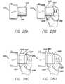
- FIGS. 26A and 26Billustrate a device for implementing the touch-based method of FIG. 25 .
- FIG. 27is a diagram of a touch-based method in accordance with an exemplary embodiment of this invention.
- FIGS. 28A-28Dillustrate a sequence and a device for implementing the touch-based method of FIG. 27 .
- FIG. 29illustrates a baseball having a touch sensitive surface in accordance with an exemplary embodiment of this invention.
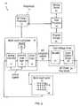
- FIG. 1is a block diagram of an exemplary computer system 50 in accordance with one embodiment of the invention.
- the computer system 50can correspond to a personal computer system, such as a desktops, laptops, tablets or handheld computer.
- the computer systemcan also correspond to a computing device, such as a cell phone, PDA, dedicated media player (such as an MP3 player), consumer electronic device, and the like.
- the exemplary computer system 50 shown in FIG. 1can include a processor 56 configured to execute instructions and to carry out operations associated with the computer system 50 .
- the processor 56can control the reception and manipulation of input and output data between components of the computing system 50 .
- the processor 56can be implemented on a single-chip, multiple chips or multiple electrical components.
- various architecturescan be used for the processor 56 , including dedicated or embedded processor, single purpose processor, controller, ASIC, and so forth.
- the processor 56 together with an operating systemcan operate to execute computer code and produce and use data.
- Operating systemsare generally well known and will not be described in greater detail.
- the operating systemcan correspond to OS/2, DOS, Unix, Linux, Palm OS, and the like.
- the operating systemcan also be a special purpose operating system, such as those used for limited purpose appliance-type computing devices.
- the operating system, other computer code and datacan reside within a memory block 58 that can be operatively coupled to the processor 56 .
- Memory block 58can generally provide a place to store computer code and data that are used by the computer system 50 .
- the memory block 58can include Read-Only Memory (ROM), Random-Access Memory (RAM), hard disk drive and/or the like.
- the informationcould also reside on a removable storage medium and loaded or installed onto the computer system 50 when needed.
- Removable storage mediumscan include, for example, CD-ROM, PC-CARD, memory card, floppy disk, magnetic tape, and a network component.
- the computer system 50can also include a display device 68 that can be operatively coupled to the processor 56 .
- the display device 68can be a liquid crystal display (LCD) (e.g., active matrix, passive matrix and the like).
- the display device 68can be a monitor such as a monochrome display, color graphics adapter (CGA) display, enhanced graphics adapter (EGA) display, variable-graphics-array (VGA) display, super VGA display, cathode ray tube (CRT), and the like.
- the display devicecan also correspond to a plasma display or a display implemented with electronic inks.
- the display device 68can be generally configured to display a graphical user interface (GUI) 69 that can provide an easy to use interface between a user of the computer system and the operating system or application running thereon.
- GUIgraphical user interface
- the GUI 69can represent programs, files and operational options with graphical images, objects, or vector representations.
- the graphical imagescan include windows, fields, dialog boxes, menus, icons, buttons, cursors, scroll bars, etc. Such images can be arranged in predefined layouts, or can be created dynamically to serve the specific actions being taken by a user.
- the usercan select and/or activate various graphical images in order to initiate functions and tasks associated therewith.
- GUI 69can additionally or alternatively display information, such as non interactive text and graphics, for the user on the display device 68 .
- the computer system 50can also include an input device 70 that can be operatively coupled to the processor 56 .
- the input device 70can be configured to transfer data from the outside world into the computer system 50 .
- the input device 70can for example be used to perform tracking and to make selections with respect to the GUI 69 on the display 68 .
- the input device 70can also be used to issue commands in the computer system 50 .
- the input device 70can include a touch sensing device configured to receive input from a user's touch and to send this information to the processor 56 .
- the touch-sensing devicecan correspond to a touchpad or a touch screen. In many cases, the touch-sensing device can recognize touches, as well as the position and magnitude of touches on a touch sensitive surface.
- the touch sensing meanscan detect and report the touches to the processor 56 and the processor 56 can interpret the touches in accordance with its programming. For example, the processor 56 can initiate a task in accordance with a particular touch.
- a dedicated processorcan be used to process touches locally and reduce demand for the main processor of the computer system.
- the touch sensing devicecan be based on sensing technologies including but not limited to capacitive sensing, resistive sensing, surface acoustic wave sensing, pressure sensing, optical sensing, and/or the like. Furthermore, the touch sensing device can be based on single point sensing or multipoint sensing. Single point sensing is capable of only distinguishing a single touch, while multipoint sensing is capable of distinguishing multiple touches that occur at the same time.
- the input device 70can be a touch screen that can be positioned over or in front of the display 68 , integrated with the display device 68 , or can be a separate component, such as a touch pad.
- the computer system 50can also include capabilities for coupling to one or more I/O devices 80 .
- the I/O devices 80can correspond to keyboards, printers, scanners, cameras, microphones, speakers, and/or the like.
- the I/O devices 80can be integrated with the computer system 50 or they can be separate components (e.g., peripheral devices).
- the I/O devices 80can be connected to the computer system 50 through wired connections (e.g., cables/ports).
- the I/O devices 80can be connected to the computer system 80 through wireless connections.
- the data linkcan correspond to PS/2, USB, IR, Firewire, RF, Bluetooth or the like.
- the computer system 50can be designed to recognize gestures 85 applied to the input device 70 and to control aspects of the computer system 50 based on the gestures 85 .
- a gesturecan be defined as a stylized interaction with an input device that can be mapped to one or more specific computing operations.
- the gestures 85can be made through various hand, and more particularly finger motions. Alternatively or additionally, the gestures can be made with a stylus.
- the input device 70can receive the gestures 85 and the processor 56 can execute instructions to carry out operations associated with the gestures 85 .
- the memory block 58can include a gesture operational program 88 , which can be part of the operating system or a separate application.
- the gestural operation program 88can include a set of instructions that can recognize the occurrence of gestures 85 and can inform one or more software agents of the gestures 85 and/or what action(s) to take in response to the gestures 85 . Additional details regarding the various gestures that can be used as input commands are discussed further below.
- the input device 70can relay gesture information to the processor 56 .
- the processor 56can interpret the gestures 85 and control different components of the computer system 50 , such as memory 58 , a display 68 and I/O devices 80 , based on the gestures 85 .
- the gestures 85can be identified as commands for performing actions in applications stored in the memory 58 , modifying image objects shown on the display 68 , modifying data stored in memory 58 , and/or for performing actions in I/O devices 80 .
- the gesturescan be single point or multipoint gestures; static or dynamic gestures; continuous or segmented gestures; and/or the like.
- Single point gesturescan be those gestures that can be performed with a single contact point, e.g., the gesture can be performed with a single touch as for example a single finger, a palm or a stylus.
- Multipoint gesturescan be those gestures that can be performed with multiple points, e.g., the gesture can be performed with multiple touches as for example multiple fingers, fingers and palms, a finger and a stylus, multiple styli and/or any combination thereof.
- Static gesturescan be those gestures that do not include motion
- dynamic gesturescan be those gestures that do include motion.
- Continuous gesturescan be those gestures that are performed in a single stroke
- segmented gesturescan be those gestures that are performed in a sequence of steps or strokes.
- FIG. 1illustrates the input device 70 and the display 68 as two separate boxes for illustration purposes, the two boxes can be realized on one device.
- FIG. 2illustrates an exemplary computing system 10 that can use a multi-touch panel 24 as an input device for gestures; the multi-touch panel 24 can at the same time be a display panel.
- the computing system 10can include one or more multi-touch panel processors 12 dedicated to the multi-touch subsystem 27 .
- the multi-touch panel processor functionalitycan be implemented by dedicated logic, such as a state machine.
- Peripherals 11can include, but are not limited to, random access memory (RAM) or other types of memory or storage, watchdog timers and the like.
- Multi-touch subsystem 27can include, but is not limited to, one or more analog channels 17 , channel scan logic 18 and driver logic 19 .
- Channel scan logic 18can access RAM 16 , autonomously read data from the analog channels and provide control for the analog channels. This control can include multiplexing columns of multi-touch panel 24 to analog channels 17 . In addition, channel scan logic 18 can control the driver logic and stimulation signals being selectively applied to rows of multi-touch panel 24 . In some embodiments, multi-touch subsystem 27 , multi-touch panel processor 12 and peripherals 11 can be integrated into a single application specific integrated circuit (ASIC).
- ASICapplication specific integrated circuit
- Driver logic 19can provide multiple multi-touch subsystem outputs 20 and can present a proprietary interface that drives high voltage driver, which can include decoder 21 and subsequent level shifter and driver stage 22 , although level-shifting functions could be performed before decoder functions.
- Level shifter and driver 22can provide level shifting from a low voltage level (e.g. CMOS levels) to a higher voltage level, providing a better signal-to-noise (S/N) ratio for noise reduction purposes.
- Decoder 21can decode the drive interface signals to one out of N outputs, whereas N is the maximum number of rows in the panel. Decoder 21 can be used to reduce the number of drive lines needed between the high voltage driver and multi-touch panel 24 .
- Each multi-touch panel row input 23can drive one or more rows in multi-touch panel 24 .
- driver 22 and decoder 21can also be integrated into a single ASIC, be integrated into driver logic 19 , or in some instances be unnecessary.
- the multi-touch panel 24can include a capacitive sensing medium having a plurality of row traces or driving lines and a plurality of column traces or sensing lines, although other sensing media can also be used.
- the row and column tracescan be formed from a transparent conductive medium, such as Indium Tin Oxide (ITO) or Antimony Tin Oxide (ATO), although other transparent and non-transparent materials, such as copper, can also be used.
- ITOIndium Tin Oxide
- ATOAntimony Tin Oxide
- the row and column tracescan be formed on opposite sides of a dielectric material, and can be perpendicular to each other, although in other embodiments other orientations can be possible, such as a non-orthogonal orientation and a polar orientation.
- the sensing linescan be concentric circles and the driving lines can be radially extending lines (or vice versa).
- the terms “row” and “column,” “first dimension” and “second dimension,” or “first axis” and “second axis” as used hereinare intended to encompass not only orthogonal grids, but the intersecting traces of other geometric configurations having first and second dimensions (e.g. the concentric and radial lines of a polar-coordinate arrangement).
- the rows and columnscan be formed on a single side of a substrate, or can be formed on two separate substrates separated by a dielectric material. In some instances, an additional dielectric cover layer can be placed over the row or column traces to strengthen the structure and protect the entire assembly from damage.
- the tracescan essentially form two electrodes (although more than two traces could intersect as well).
- Each intersection of row and column tracescan represent a capacitive sensing node and can be viewed as picture element (pixel) 26 , which can be particularly useful when multi-touch panel 24 is viewed as capturing an “image” of touch.
- pixelpicture element
- the capacitance between row and column electrodesappears as a stray capacitance on all columns when the given row is held at DC and as a mutual capacitance Csig when the given row is stimulated with an AC signal.
- the presence of a finger or other object near or on the multi-touch panelcan be detected by measuring changes to Csig.
- the columns of multi-touch panel 124can drive one or more analog channels 17 (also referred to herein as event detection and demodulation circuits) in multi-touch subsystem 27 .
- each columncan be coupled to one dedicated analog channel 17 .
- the columnscan be couplable via an analog switch to a fewer number of analog channels 17 .
- Computing system 10can also include host processor 14 for receiving outputs from multi-touch panel processor 12 and performing actions based on the outputs that can include, but are not limited to, moving an object such as a cursor or pointer, scrolling or panning, adjusting control settings, opening a file or document, viewing a menu, making a selection, executing instructions, operating a peripheral device connected to the host device, etc.
- Host processor 14which can be a personal computer CPU, can also perform additional functions that can not be related to multi-touch panel processing, and can be coupled to program storage 15 and display device 13 such as an LCD display for providing a user interface (UI) to a user of the device.
- UIuser interface
- FIG. 2illustrates a dedicated MT panel processor 12
- the multi-touch subsystemcan be controlled directly by the host processor 14 .
- the multi-touch panel 24 and the display device 13can be integrated into one single touch-screen display device. Further details of multi-touch sensor detection, including proximity detection by a touch panel, is described in commonly assigned co-pending applications, including U.S. application Ser. No. 10/840,862, published on May 11, 2006 as U.S. Patent Publication No. US2006/0097991, U.S. application Ser. No. 11/428,522, published on Oct. 26, 2006 as U.S. Patent Publication No. US2006/0238522, and U.S. application Ser. No. 11/649,998 entitled “Proximity and Multi-Touch Sensor Detection and Demodulation,” filed on Jan. 3, 2007, the entirety of each of which are hereby incorporated herein by reference.
- FIG. 3illustrates a multipoint processing method 100 , in accordance with one embodiment of the invention.
- the multipoint processing method 100can for example be performed in the system shown in FIG. 1 or 2 .
- the multipoint processing method 100generally begins at block 102 where images can be read from a multipoint input device, and more particularly a multipoint touch screen.
- imagescan be read from a multipoint input device, and more particularly a multipoint touch screen.
- imagecan come in other forms.
- the image read from the touch screencan provide magnitude (Z) as a function of position (x and y) for each sensing point or pixel of the touch screen.
- the magnitudecan, for example, reflect the capacitance measured at each point.
- multipoint processing method 100proceeds to block 104 where the image can be converted into a collection or list of features.
- Each featurecan represent a distinct input such as a touch.
- each featurecan include its own unique identifier (ID), x coordinate, y coordinate, Z magnitude, angle ⁇ , area A, and the like.
- FIGS. 4A and 4Billustrate a particular image 120 in time.
- image 120there are two features 122 based on two distinct touches. The touches can for example be formed from a pair of fingers touching the touch screen.
- each feature 122can include unique identifier (ID), x coordinate, y coordinate, Z magnitude, angle theta, and area A.
- the first feature 122 Acan be represented by ID 1 , X 1 , Y 1 , Z 1 , ⁇ 1 , A 1 and the second feature 122 B can be represented by ID 2 , X 2 , Y 2 , Z 2 , ⁇ 2 , A 2 .
- This datacan be outputted for example using a multi-touch protocol.
- the raw datacan be typically received in a digitized form, and can include values for each node of the touch screen.
- the valuescan be between 0 and 256 where 0 equates to no touch pressure and 256 equates to full touch pressure.
- the raw datacan be filtered to reduce noise. Once filtered, gradient data, which indicates the topology of each group of connected points, can be generated.
- the boundaries for touch regionscan be calculated based on the gradient data (i.e., a determination can be made as to which points are grouped together to form each touch region).
- a watershed algorithmcan be used.
- the data for each of the touch regionscan be calculated (e.g., X, Y, Z, ⁇ , A).
- multipoint processing method 100proceeds to block 106 where feature classification and groupings can be performed.
- the identity of each of the featurescan be determined.
- the featurescan be classified as a particular finger, thumb, palm or other object. Once classified, the features can be grouped.
- the manner in which the groups can be formedcan be widely varied. In most cases, the features can be grouped based on some criteria (e.g., they carry a similar attribute). For example, the two features shown in FIGS. 4A and 4B can be grouped together because each of these features is located in proximity to each other or because they are from the same hand.
- the groupingcan include some level of filtering to filter out features that are not part of the touch event.
- one or more featurescan be rejected because they either meet some predefined criteria or because they do not meet some criteria.
- one of the featurescan be classified as a thumb located at the edge of a tablet PC. Because the thumb is being used to hold the device rather than being used to perform a task, the feature generated therefrom can be rejected, i.e., not considered part of the touch event being processed.
- the multipoint processing method 100proceeds to block 108 where key parameters for the feature groups can be calculated.
- the key parameterscan include distance between features, x/y centroid of all features, feature rotation, total pressure of the group (e.g., pressure at centroid), and the like.
- the calculationcan include finding the centroid C, drawing a virtual line 130 to each feature from the centroid C, defining the distance D for each virtual line (D 1 and D 2 ), and then averaging the distances D 1 and D 2 .
- the parameter valuescan be reported.
- the parameter valuescan be typically reported with a group identifier (GID) and number of features within each group (in this case three). In most cases, both initial and current parameter values can be reported.
- the initial parameter valuescan be based on touch down, i.e., when the user sets their fingers on the touch screen, and the current values can be based on any point within a stroke occurring after touch down.
- blocks 102 - 108can be repetitively performed during a user stroke thereby generating a plurality of sequentially configured signals.
- the initial and current parameterscan be compared in later steps to perform actions in the system.
- UI elementscan be buttons boxes, lists, sliders, wheels, knobs, pictures, documents, icons, etc.
- Each UI elementcan represent a component or control of the user interface.
- the application behind the UI element(s)can have access to the parameter data calculated in block 108 .
- the applicationcan rank the relevance of the touch data to the UI element corresponding there to. The ranking can be based on some predetermined criteria. The ranking can include producing a figure of merit, and whichever UI element has the highest figure of merit, giving it sole access to the group.
- the rankingcan include determining proximity of the centroid (or features) to the image object associated with the UI element.
- the multipoint processing method 100proceeds to blocks 112 and 114 .
- the blocks 112 and 114can be performed approximately at the same time. From the user perspective, in one embodiment, the blocks 112 and 114 appear to be performed concurrently.
- one or more actionscan be performed based on differences between initial and current parameter values, and can also be based to a UI element to which they can be associated, if any.
- user feedback pertaining to the one or more actions being performedcan be provided.
- user feedbackcan include display, audio, tactile feedback and/or the like.
- FIG. 6is a parameter calculation method 150 , in accordance with one embodiment of the invention.
- the parameter calculation method 150can, for example, correspond to block 108 shown in FIG. 3 .
- the parameter calculation method 150generally begins at block 152 where a group of features can be received. Following block 152 , the parameter calculation method 150 proceeds to block 154 where a determination can be made as to whether or not the number of features in the group of features has changed. For example, the number of features can have changed due to the user picking up or placing an additional finger. Different fingers can be needed to perform different controls (e.g., tracking, gesturing). If the number of features has changed, the parameter calculation method 150 proceeds to block 156 where the initial parameter values can be calculated.
- the parameter calculation method 150proceeds to block 158 where the current parameter values can be calculated. Thereafter, the parameter calculation method 150 proceeds to block 160 where the initial and current parameter values can be reported.
- the initial parameter valuescan contain the average initial distance between points (or Distance (AVG) initial) and the current parameter values can contain the average current distance between points (or Distance (AVG) current). These can be compared in subsequent steps in order to control various aspects of a computer system.
- gesturescan be created to detect and effect a user command to resize a window, scroll a display, rotate an object, zoom in or out of a displayed view, delete or insert text or other objects, etc.
- Gesturescan also be used to invoke and manipulate virtual control interfaces, such as volume knobs, switches, sliders, keyboards, and other virtual interfaces that can be created to facilitate human interaction with a computing system or a consumer electronic item.
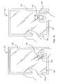
- a rotate gesture for controlling a virtual volume knob 170 on a GUI interface 172 of a display 174 of a tablet PC 175will be described.
- the userplaces their fingers 176 on a multipoint touch screen 178 .
- the virtual control knobcan already be displayed, or the particular number, orientation or profile of the fingers at touch down, or the movement of the fingers immediately thereafter, or some combination of these and other characteristics of the user's interaction can invoke the virtual control knob to be displayed.
- the computing systemcan associate a finger group to the virtual control knob and can make a determination that the user intends to use the virtual volume knob.
- This associationcan also be based in part on the mode or current state of the computing device at the time of the input. For example, the same gesture can be interpreted alternatively as a volume gesture if a song is currently playing on the computing device, or as a rotate command if an object editing application is being executed.
- Other user feedbackcan be provided, including for example audible or tactile feedback.
- the user's fingers 176thereafter can be rotated around the knob 170 in order to simulate turning the knob 170 .
- audible feedbackin the form of a clicking sound or tactile feedback in the form of vibration, for example, can be provided as the knob 170 is “rotated.”
- the usercan also use their other hand to hold the tablet PC 175 .
- the multipoint touch screen 178can detect at least a pair of images.
- a first image 180can be created at touch down, and at least one other image 182 can be created when the fingers 176 are rotated.
- Each imagecan represent a profile of the fingers in contact with the touch screen at a particular instant in time. These images can also be referred to as touch images.
- touch imagescan also be referred to as touch images.
- imagedoes not mean that the profile is displayed on the screen 178 (but rather imaged by the touch sensing device).
- the term “image”is used, the data can be in other forms representative of the touch plane at various times.
- each of the images 180 and 182can be converted to a collection of features 184 .
- Each feature 184can be associated with a particular touch as for example from the tips each of the fingers 176 surrounding the knob 170 as well as the thumb of the other hand 177 used to hold the tablet PC 175 .
- the features 184can be classified, i.e., each finger/thumb can be identified, and grouped for each of the images 180 and 182 .
- the features 184 A associated with the knob 170can be grouped together to form group 188 and the feature 184 B associated with the thumb is filtered out.
- the thumb feature 184 Bcan be treated as a separate feature by itself (or in another group), for example, to alter the input or operational mode of the system or to implement another gesture, for example, a slider gesture associated with an equalizer slider displayed on the screen in the area of the thumb (or other finger).
- the key parameters of the feature group 188can be calculated for each image 180 and 182 .
- the key parameters associated with the first image 180can represent the initial state and the key parameters of the second image 182 can represent the current state.
- the knob 170can be the UI element associated with the feature group 188 because of its proximity to the knob 170 .
- the key parameter values of the feature group 188 from each image 180 and 182can be compared to determine the rotation vector, i.e., the group of features rotated five (5) degrees clockwise from the initial to current state.
- the initial feature group (image 180 )can be shown in dashed lines while the current feature group (image 182 ) can be shown in solid lines.
- the speaker 192 of the tablet PC 175can increase (or decrease) its output in accordance with the amount of rotation of the fingers 176 , i.e., increase the volume by 5% based on rotation of 5 degrees.
- the display 174 of the tablet PCcan also adjust the rotation of the knob 170 in accordance with the amount of rotation of the fingers 176 , i.e., the position of the knob 170 rotates five (5) degrees. In most cases, the rotation of the knob can occur simultaneously with the rotation of the fingers, i.e., for every degree of finger rotation the knob can rotate a degree. In essence, the virtual control knob follows the gesture occurring on the screen.
- an audio unit 194 of the tablet PCcan provide a clicking sound for each unit of rotation, e.g., provide five clicks based on rotation of five degrees.
- a haptics unit 196 of the tablet PC 175can provide a certain amount of vibration or other tactile feedback for each click thereby simulating an actual knob.
- additional gesturescan be performed simultaneously with the virtual control knob gesture.
- more than one virtual control knobcan be controlled at the same time using both hands, i.e., one hand for each virtual control knob.
- one or more slider barscan be controlled at the same time as the virtual control knob, i.e., one hand operates the virtual control knob, while at least one finger and maybe more than one finger of the opposite hand operates at least one slider and maybe more than one slider bar, e.g., slider bar for each finger.
- the UI elementcan be a virtual scroll wheel.
- the virtual scroll wheelcan mimic an actual scroll wheel such as those described in U.S. Patent Publication Nos. US2003/0076303A1, US2003/0076301A1, and US2003/0095096A1, all of which are herein incorporated by reference.
- FIG. 8is a diagram of a touch-based method 700 in which a gesture on a touch sensitive surface of a sensing device can be used to remotely control another device.
- images of the gesturecan be captured as the user inputs the gesture on the touch sensitive surface.
- the gesturecan be, for example, placing one finger at a location on the touch sensitive surface and rolling the finger as a joystick.
- the images of the gesturecan produce snapshots of finger contacts with the touch sensitive surface.
- each imagecan be analyzed to identify one or more touches at block 704 . Data or parameters for each touch, such as the x coordinate and y coordinate, can be calculated.
- the data or parameters for touchescan be compared.
- the sensing device at block 708can generate a control signal based on the comparison.
- the signalcan be then transmitted to another device to remotely control it at block 710 in accordance with the content of the signal.
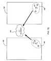
- FIG. 9illustrates one system for implementing the touch-based method of FIG. 8 .
- the systemcan comprise a device such as tablet PC 720 having a touch sensitive surface 722 , such as a touch pad or a-touch sensitive display screen.
- a usercan input a gesture on surface 722 .
- FIG. 9illustrates one example of a user performing a rolling gesture, as indicated by the arrow, with his index finger 726 on surface 722 .
- the tablet PC 724can have an antenna for transmitting signals to another device such as car 728 .
- the car 728can have an antenna 730 for receiving signals transmitted from tablet PC 720 .
- car 728can have the processing capability well known in the art of analyzing the received signal and performing one or more actions based on the contents of the signal.
- the wireless connection between tablet PC 720 and car 728can correspond to any well-known wireless protocol such as Bluetooth, WiFi and the like.
- tablet PC 720 and car 728can be connected together through a wired connection.
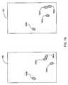
- FIGS. 10A-10Cillustrate a sequence using the touch-based method 700 with the system of FIG. 9 .
- FIGS. 10A-10Cshow three images 740 , 745 and 750 captured by tablet PC 720 as finger 726 performs two rolling gestures on surface 722 .
- FIG. 10Aillustrates the image captured when the user first sets down his finger 726 on surface 722 .
- the image 740can be analyzed by the tablet PC 720 to identify touch 742 . Once identified, data or parameters of touch 742 , such as x coordinate X1 and y coordinate Y1, can be determined.
- the x and y coordinatescan correspond to the center of a touch in a given image, but the x and y coordinates can correspond to other geometrical features of the touch.
- FIG. 10Billustrates the image captured after the user has rolled his finger 726 to the right.
- the initial touch down 742can be shown with dotted lines, while touch 747 can be the touch resulting from the roll.
- touch 747can be the touch resulting from the roll.
- the userhas lifted a portion of his finger 726 previously touching surface 722 . This portion corresponds to section A 1 having horizontal hatch marks.
- the userhas also placed a portion of his finger 726 , which was not previously on surface 722 , onto surface 722 .
- This portioncan correspond to section A 2 having vertical hatch marks.
- a portion of his finger indicated without any hatch marksremains in contact throughout the roll.
- data or parameters for touch 747such as x coordinate X2 and y coordinate Y2 can be different than coordinates X1 and Y1 for touch 742 .
- the data or parameters between these consecutive imagescan be compared and the difference between them can be used to generate a control signal for remotely controlling the car 728 .
- a comparison of x coordinates X1 and X2can indicate a roll direction or vector at least to the right.
- the sensing devicecan generate a control signal directing the car 728 to move in the direction of the roll and transmit that signal to the car 728 to remotely effectuate a movement operation.
- a comparison of x coordinates X1 and X2can also be used to provide other means of control beyond directional control.
- the amount of difference in the x coordinates X1 and X2can be considered the magnitude of the roll, e.g., how pronounced the user has rolled his finger in a given direction.
- the magnitude of the rollcan be used, for example, to generate a signal for controlling the velocity of the car 728 .
- the usercan control the velocity by controlling the magnitude of the roll. For example, a more pronounced roll will correlate to the car operating with greater velocity.
- one gesturesuch as the roll of a finger in one direction, can both control the direction and velocity of the car.
- the roll of one finger on surface 772can be used to control the direction, and the placement of two fingers on surface 722 can indicate a change in mode, such that a subsequent roll of one or more of the two fingers controls velocity rather than direction.
- the comparisonis not limited to a single type of data or parameter.
- the Y1 and Y2 coordinatescan also be compared and a signal generated to move the car in a backwards or forward direction based on the comparison after or in conjunction with the car's movement in the x direction.
- each touchcan be defined by a number of touch data or parameters and any one or more of these data or parameters can be the basis for the generated control signal.
- the direction and magnitude of the rolldoes not have to be mapped to the direction and velocity of the controlled device's movement. The direction and magnitude of the roll can be mapped to other actions such as turning the device on or off.
- the comparison between two imagesdoes not necessarily have to reflect a difference in a touch data to generate a signal.
- a touch on a specific portion of the touch sensitive surfacecan be correlated to turning on the car.
- Such a touchcan have the same or essentially the same data over several images. This similarity of data over a number of images can be the basis of generating a control signal as much as a dissimilarity as discussed above.
- FIG. 10Cillustrates an image 750 of a second roll of the user's finger 726 toward the top of surface 722 (not shown in FIG. 9 ).
- the rollcan be continuous with the roll of FIG. 10B or as a separate roll at a different time.
- the previous touch 747is shown with dotted lines, while touch 752 is the touch resulting from the roll.
- the userhas lifted a portion of his finger 726 previously touching surface 722 . This portion can correspond to section A 3 having horizontal hatch marks.
- the userhas also placed a portion of his finger 726 , which was not previously on the surface 722 , onto surface 722 . This portion can correspond to section A 4 having vertical hatch marks.
- touch datasuch as an x coordinate X3 and a y coordinate Y3 for touch 752 can be different than coordinates X2 and Y2 from touch 747 .
- touch datacan be compared and the difference between them can be used to generate a control signal in the same manner as discussed above with respect to FIG. 10B .
- a user's gesturessuch as a roll
- a touch sensitive surface of a sensing devicecan be used to remotely control another device such as a car.
- the usercan use his finger as a joystick to control the movement of the car in a number of ways (such as its direction and velocity) with a single gesture.
- FIGS. 10A-10Cshow an image of a single finger touch
- multi-finger touchescan also be used, such as a combination of the index finger with the thumb.
- the index finger and thumbcan be pressed together or separated.
- FIGS. 10A-10Cshow only rolls, different type of gestures can be combined to more efficiently operate the controlled device.
- the directional movementcan be controlled by returning the joystick to the center or null.
- a quick right movementcan be performed by tapping the joystick to the right and having the joystick return to the center.
- the directional operationcan be performed, as discussed above, with a slight right roll of a finger on a touch sensitive surface.
- the return to center or nullcan be performed by a subsequent push gesture forward or to the north of the surface.
- the pushing gesturecan be used to generate a signal to be transmitted to the car such that the car adjusts back to the center-line.
- a combination of a roll gesture followed by a push gesturecan be used to efficiently operate the controlled device, such as by preventing over-rolling the finger and thereby over-steering the controlled object in a given direction.
- Gestures other than a pushcan be used to perform such control and even other types of operations. For example, gestures such as subtracting fingers to slow down or stop altogether the controlled device or adding fingers to increase the rate that the operation is performed can also be used.
- a remotely controlled deviceis not limited to a car as illustrated in FIG. 9 .
- the devicecan be any object that can receive a signal and have operations to be controlled. This can include robots, vacuums, machinery and consumer electronic devices such as televisions, computers, dedicated music players, mobile phones and the like.
- FIG. 11is a diagram of a touch-based method 800 in which a rolling gesture on a touch sensitive surface of a sensing device can be used to operate an object or element displayed on the surface.
- the sensing devicecan detect the presence of one or more fingers in relation to the displayed object. This can indicate to the sensing device that the user wishes to operate the object or element.
- sensing devicecan detect a roll of the one or more fingers over the object. The user can perform this gesture to operate the selected object in the manner that he wishes. It should be noted that the detection at blocks 805 and 810 can be performed in the same manner as discussed above.
- Images of the touch sensitive surfacecan be captured, analyzed and compared to determine the manual action that is being performed on the surface.
- the sensing devicecan determine the desired operation and can generate a corresponding control signal at block 815 .
- the detectioncan, for example, analyze parameters such as the direction and/or magnitude of the roll.
- the signalcan be then used to operate the object at block 820 .
- the signalcan direct a scroll through the object in a direction corresponding to the direction of the roll.
- FIG. 12illustrates a device for implementing the touch-based method of FIG. 11 .
- the systemcan include a device such as dedicated media player 830 having touch sensitive display 832 .
- Display 832displays one or more graphical objects or elements.
- display 832displays a one-dimensional timeline 835 for an audio performance played by media player 830 .
- the timelinecan include a bar 837 indicating the current play position of the audio performance. As the audio performance proceeds, bar 832 can move along the timeline from left to right.
- a usercan input a touch on any portion of display 835 , including over the timeline 835 , with one or more fingers.
- FIG. 12illustrates that the user is inputting a touch with his index finger 839 on timeline 835 .
- FIGS. 13A-13Cprovide a more detailed view of timeline 835 illustrated in FIG. 12 .
- Timeline 835provides a starting time 840 of the performance and an ending time 842 .
- Above bar 837the time 841 of the current play position is shown.
- FIGS. 13A-13Calso illustrate a sequence using the touch-based method 800 with the device of FIG. 12 .
- the devicecan detect the user placing his finger 839 on timeline 835 as illustrated in FIG. 13A . At that moment, the current time 841 of the play position is 1:05. That is, 1:05 minutes of the performance has elapsed.
- the devicecan then detect a roll of finger 839 toward the right as indicated by the arrow above finger 839 in FIG. 13B .
- This gesture over the timelinecan indicate that the user wants to change the play position of bar 837 by scrolling or translating through timeline 835 .
- the rollcan be analyzed to determine its direction and magnitude and a control signal can be generated based on this analysis. As shown in FIG.
- bar 837begins to scroll to the right corresponding to the direction of the roll.
- the rate or velocity of the scroll through the timelinecan be based on the magnitude of the roll.
- FIG. 13Bshows that the roll has slowly moved bar 837 from a position at 1:05 minutes to a current position of 3:48 minutes.
- the usercan stop the scroll with any number of gestures, such as by lifting his finger 839 or reversing the direction of the roll.
- FIG. 13Cillustrates bar 837 at time 5:50 and advancing faster than in FIG. 13B as indicated by the double arrows near bar 837 .
- the rolling gesturedoes not have to be performed on the object for the object to be operated.
- the usercan perform a gesture on a portion of the display separated from the timeline itself.
- the gesturecan also be performed on a touch sensitive surface separated from the display of the object, such as a touchpad located below a display of a user interface.
- Other data from the rollcould also be used in operating the element, such as the pressure of the roll or the location of the roll with respect to the timeline.
- the objectdoes not have to be a timeline for an audio or video performance.
- the objectfor example, can be a displayed video clip in which the user can scroll through the clip by rolling his finger over the displayed clip.
- the rollcan be mapped to other operations. For example, a roll to the right can be used to indicate play while a roll to the left can be used to indicate stopping play.
- the gesture for operating of the devicedoes not have to relate to a displayed object or element.
- a rolling gesture to the rightcan be used to turn on the device and a rolling gesture to the left can be used to turn off the device.
- Each of these gesturesis not connected to any object or element displayed on the device.
- FIG. 14is a diagram of a touch-based method 200 in accordance with one embodiment of the invention.
- the methodgenerally begins at block 202 where a user input that occurs over a multipoint sensing device is detected.
- the user inputcan include one or more touch inputs, with each touch input having a unique identifier.
- the touch-based method 200proceeds to block 204 where the user input can be classified as a tracking or selection input when the user input includes a single unique identifier (one touch input), or can be classified as a gesture input when the user input includes at least two unique identifiers (more than one touch input). If the user input is classified as a tracking input, the touch-based method 200 proceeds to block 206 where tracking can be performed corresponding to the user input.
- the touch-based method 200proceeds to block 208 where one or more gesture control actions can be performed corresponding the user input.
- the gesture control actionscan be based at least in part on changes that occur with or between the at least two unique identifiers.
- FIG. 15is a diagram of a touch-based method 250 in accordance with one embodiment of the invention.
- the touch-based method 250generally begins at block 252 where an initial image can be captured during an input stroke on a touch sensitive surface. Following block 252 , the touch-based method 250 proceeds to block 254 where the touch mode can be determined based on the initial image. For example, if the initial image includes a single unique identifier then the touch mode can correspond to a tracking or selection mode. On the other hand, if the image includes more than one unique identifier, then the touch mode can correspond to a gesture mode.
- the touch-based method 250proceeds to block 256 where a next image can be captured during the input stroke on the touch sensitive surface. Images can be typically captured sequentially during the stroke and thus there can be a plurality of images associated with the stroke.
- touch-based method 250proceeds to block 258 where a determination can be made as to whether the touch mode changed between capture of the initial image and capture of the next image. If the touch mode changed, the touch-based method 250 proceeds to block 260 where the next image can be set as the initial image and thereafter the touch mode can be again determined at block 254 based on the new initial image. If the touch mode stayed the same, the touch-based method 250 proceeds to block 262 where the initial and next images can be compared and one or more control signals can be generated based on the comparison.
- FIG. 16is a diagram of a touch-based method 300 in accordance with one embodiment of the invention.
- the touch-based method 300begins at block 302 where an image object, which can be a GUI object, can be output.
- an image objectwhich can be a GUI object
- a processorcan instruct a display to display a particular image object.
- the touch-based method 300proceeds to block 304 where a gesture input can be received over the image object.
- a usercan set or move their fingers in a gestural way on the surface of the touch screen and while over the displayed image object.
- the gestural inputcan include one or more single gestures that occur consecutively or multiple gestures that occur simultaneously.
- Each of the gesturescan generally have a particular sequence, motion, or orientation associated therewith.
- a gesturecan include spreading fingers apart or closing fingers together, rotating the fingers, translating the fingers, and/or the like.
- the touch-based method 300proceeds to block 306 where the image object can be modified based on and in unison with the gesture input.
- modifiedit is meant that the image object can change according to the particular gesture or gestures being performed.
- unisonit is meant that the changes can occur approximately while the gesture or gestures are being performed.
- the image objectcan follow the motion of the fingers. For example, spreading of the fingers can simultaneously enlarge the object, closing of the fingers can simultaneously reduce the image object, rotating the fingers can simultaneously rotate the object, and translating the fingers can allow simultaneous panning or scrolling of the image object.
- block 306can include determining which image object is associated with the gesture being performed, and thereafter locking the displayed object to the fingers disposed over it such that the image object changes in accordance with the gestural input. By locking or associating the fingers to the image object, the image object can continuously adjust itself in accordance to what the fingers are doing on the touch screen. Often the determination and locking can occur at touch down, i.e., when the finger is positioned on the touch screen.
- FIG. 17is a diagram of a zoom gesture method 350 , in accordance with one embodiment of the invention.
- the zoom gesturecan be performed on a multipoint touch screen such as the multi-touch panel 24 shown in FIG. 2 .
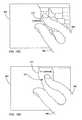
- the zoom gesture method 350generally begins at block 352 where the presence of at least a first finger and a second finger can be detected on a touch sensitive surface at the same time.
- the presence of at least two fingerscan be configured to indicate that the touch is a gestural touch rather than a tracking touch based on one finger.
- the presence of only two fingerscan indicate that the touch is a gestural touch.
- any number of more than two fingerscan indicate that the touch is a gestural touch.
- the gestural touchcan be configured to operate whether two, three, four or more fingers are touching, and even if the numbers change during the gesture, i.e., only need a minimum of two fingers at any time during the gesture.
- the zoom gesture method 350proceeds to block 354 where the distance between at least the two fingers can be compared.
- the distancecan be from finger to finger or from each finger to some other reference point as for example the centroid. If the distance between the two fingers increases (spread apart), a zoom-in signal can be generated as shown in block 356 . If the distance between two fingers decreases (close together), a zoom-out signal can be generated as shown in block 358 .
- the touch down of the fingerscan associate or lock the fingers to a particular image object being displayed.
- the touch sensitive surfacecan be a touch screen, and the image object can be displayed on the touch screen. This typically occurs when at least one of the fingers can be positioned over the image object.
- the zoom-in signalcan be used to increase the size of the embedded features in the image object and when the fingers are pinched together, the zoom-out signal can be used to decrease the size of embedded features in the object.
- the zoomingtypically occurs within a predefined boundary such as the periphery of the display, the periphery of a window, the edge of the image object, and/or the like.
- the embedded featurescan be formed on a plurality of layers, each of which represents a different level of zoom.
- the amount of zoomingvaries according to the distance between the two objects.
- the zoomingtypically can occur substantially simultaneously with the motion of the objects. For instance, as the fingers spread apart or closes together, the object zooms in or zooms out at the same time.
- This methodologyis directed at zooming, it should be noted that it can also be used for enlarging or reducing.
- the zoom gesture method 350can be particularly useful in graphical programs such as publishing, photo, and drawing programs.
- zoomingcan be used to control a peripheral device such as a camera, i.e., when the finger is spread apart, the camera zooms out, and when the fingers are closed the camera zooms in.
- FIGS. 18A-18Hillustrate a zooming sequence using the method described above.
- FIG. 18Aillustrates a display presenting an image object 364 in the form of a map of North America with embedded levels which can be zoomed. In some cases, as shown, the image object can be positioned inside a window that forms a boundary of the image object 364 .
- FIG. 18Billustrates a user positioning their fingers 366 over a region of North America 368 , particularly the United States 370 and more particularly California 372 . In order to zoom in on California 372 , the user can start to spread their fingers 366 apart as shown in FIG. 18C .
- the mapcan zoom in further on Northern California 374 , then to a particular region of Northern California 374 , then to the Bay area 376 , then to the peninsula 378 (e.g., the area between San Francisco and San Jose Area), and then to the city of San Carlos 380 located between San Francisco and San Jose as illustrated in FIGS. 18D-18H .
- the fingers 366can be closed back together following the sequence described above, but in reverse.
- FIG. 19is a diagram of a zoom gesture method described above with respect to FIG. 17 used in conjunction with the rolling gesture method described above with respect to FIG. 11 .
- the combination of gesturescan be performed on a touch sensitive surface of a device.
- the method 850begins at block 855 where the presence of a first finger and a second finger can be detected on the touch sensitive surface.
- images of the fingerscan be captured and analyzed to compare the distance between the two fingers at block 865 and to detect whether one or both fingers have been rolled at block 875 .
- the analysis of the imagescan be performed in the same manner as discussed above. For example, touches can be identified in the images and touch data between images can be compared to determine if the distance between the fingers has increased or decreased or whether one or both fingers has rolled. Such analysis can determine whether the user has performed a zoom gesture, a roll gesture or even both at the same time.
- a zoom in signalcan be generated at block 865 as discussed above.
- a zoom out signalcan be generated at block 875 as discussed above.
- a signalcan be generated in accordance with the direction and/or magnitude of the roll at block 880 . If both a zoom gesture and a roll gesture are performed, two signals can be simultaneously generated to perform a zoom operation and a roll operation. As can be appreciated, images of the fingers can be repetitively captured and analyzed, so that consecutive gestures, such as a zoom gesture followed by a roll gesture, can also be detected.
- FIGS. 20A-20Cillustrate a zooming and rolling sequence using the touch based method 900 described above.
- a zoom gesture and a roll gesturecan be performed simultaneously and another roll gesture is performed thereafter.
- FIGS. 20A-20Cillustrate touch sensitive surface 900 of a device displaying a timeline 905 of an audio performance such as described with respect to FIGS. 12-13C .
- the timelinecan display a bar 910 corresponding to the current play position of the audio performance.
- Surface 900can display the time 915 when the performance began, the time 917 of the current play position and the time 919 when the performance will end. Specifically, the performance begins at 0 minutes and 0 seconds, the current play position is at 0.50 seconds and the performance terminates at 1 hour.
- the one-hour length of the performancecan make it difficult for the user to adequately scroll to a desired play position early in the performance, such as in the first five minutes.
- a desired play positionearly in the performance, such as in the first five minutes.
- the usercan place two figures on surface 900 and perform a zoom and roll gesture simultaneously.
- FIG. 20Billustrates the user placing two fingers 925 and 930 on surface 900 .
- the devicecan detect the presence of these two fingers. As illustrated by the arrows, the distance between the fingers can be increased as finger 930 is simultaneously turned to the right. These two simultaneous gestures can indicate a zoom in and a roll to the right.
- the devicecan generates a zoom in signal to zoom in to the timeline.
- the zoom incan correspond to a change in scale of the timeline. As the distance between the fingers between fingers 925 and 930 expands, the scale can correspondingly reduce.
- the timelineis scaled down to from 0 minutes at 915 to 1 hour at 919 in FIG. 20A to 0 minutes at 915 to 10 minutes at 919 in FIG. 20B .
- the devicecan also generate a signal to scroll bar 910 in the right direction such that the bar is moved to a current play position of 4:25 at 917 in FIG. 20B .
- the merged gestures of zooming in and rollingcan allow the user to better control the position of the bar in the first five minutes of the timeline by reducing the scale of the timeline so that the rolling can be more finely controlled.
- FIG. 20Cshows that the user performing another gesture, either continuously with the gestures of FIG. 20B or at a time interval thereafter.
- the devicecan detect a roll gesture to the left by finger 925 . It can generate a signal to move the current play position from 4:25 at 917 in FIG. 20B to 3:00 minutes at 917 in FIG. 20C . Because the user has not changed the distance between his fingers in performing this roll, the scale of the timeline can remain the same.
- zoom outcan be performed to scale up the timeline. This can be useful if the performance is lengthy and the user wishes to quickly scroll to end of the performance. While the zoom in and zoom out gestures are illustrated as being performed with two fingers, others gestures can also be used. For example, zoom in could be performed by a swipe in a given direction and zoom out by a swipe in another direction.
- pan and rotatecan also be used in conjunction with the rolling gesture in a similar manner.
- the usercan pan to different portions of the timeline and roll his finger to control the current play position in the panned portioned.
- the pan and rotate gesturesare discussed below.
- FIG. 21is a diagram of a pan method 400 , in accordance with one embodiment of the invention.
- the pan gesturecan be performed on a multipoint touch screen.
- the pan method 400generally begins at block 402 where the presence of at least a first object and a second object can be detected on a touch sensitive surface at the same time.
- the presence of at least two fingerscan be configured to indicate that the touch is a gestural touch rather than a tracking touch based on one finger.
- the presence of only two fingerscan indicate that the touch is a gestural touch.
- any number of more than two fingerscan indicate that the touch is a gestural touch.
- the gestural touchcan be configured to operate whether two, three, four or more fingers are touching, and even if the numbers change during the gesture, i.e., need a minimum of only two fingers.
- the pan method 400proceeds to block 404 where the position of the two objects when the objects are moved together across the touch screen can be monitored.
- the pan method 400proceeds to block 406 were a pan signal can be generated when the position of the two objects changes relative to an initial position.
- the touch down of the fingerscan associate or lock the fingers to a particular image object displayed on the touch screen, typically, when at least one of the fingers is positioned over the position on the image object.
- the pan signalcan be used to translate the image in the direction of the fingers.
- the amount of panningcan vary according to the distance the two objects move.
- the panningtypically can occur substantially simultaneously with the motion of the objects. For instance, as the fingers move, the object can move with the fingers at the same time.
- FIGS. 22A-22Dillustrate a panning sequence based on the pan method 400 described above.
- FIG. 22Aillustrates a user positioning their fingers 366 over the map. Upon touch down, the fingers 366 can be locked to the map.
- FIG. 22Bwhen the fingers 366 are moved vertically up, the entire map 364 can be moved up thereby causing previously seen portions of map 364 to be placed outside the viewing area and unseen portions of the map 364 to be placed inside the viewing area.
- FIG. 22Billustrates a panning sequence based on the pan method 400 described above.
- the motion of the map 364can follow the motion of the fingers 366 . This process is similar to sliding a piece of paper along a table. The pressure the fingers exert on the paper can lock the paper to the fingers and when the fingers are slid across the table, the piece of paper moves with them.
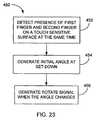
- FIG. 23is a diagram of a rotate method 450 , in accordance with one embodiment of the invention.
- the rotate gesturecan be performed on a multipoint touch screen.
- the rotate method 450generally begins at block 452 where the presence of a first object and a second object can be detected at the same time.
- the presence of at least two fingerscan be configured to indicate that the touch is a gestural touch rather than a tracking touch based on one finger.
- the presence of only two fingerscan indicate that the touch is a gestural touch.
- any number of more than two fingerscan indicate that the touch is a gestural touch.
- the gestural touchcan be configured to operate whether two, three, four or more fingers are touching, and even if the numbers change during the gesture, i.e., only need a minimum of two fingers.
- the rotate method 450proceeds to block 454 where the angle of each of the finger can be set.
- the anglescan be typically determined relative to a reference point.
- rotate method 450proceeds to block 456 where a rotate signal can be generated when the angle of at least one of the objects changes relative to the reference point.
- the touch down of the fingerscan associate or lock the fingers to a particular image object displayed on the touch screen.
- the image objectcan be associated with or locked to the fingers.
- the rotate signalcan be used to rotate the object in the direction of finger rotation (e.g., clockwise, counterclockwise).
- the amount of object rotationvaries according to the amount of finger rotation, i.e., if the fingers move 5 degrees then so will the object.
- the rotationtypically can occur substantially simultaneously with the motion of the fingers. For instance, as the fingers rotate, the object can rotate with the fingers at the same time.
- FIGS. 24A-24Cillustrate a rotating sequence based on the method describe above.
- FIG. 24Aillustrates a user positioning their fingers 366 over the map 364 .
- the fingers 366can be locked to the map 364 .
- FIG. 24Bwhen the fingers 366 are rotated in a clockwise direction, the entire map 364 can be rotated in the clockwise direction in accordance with the rotating fingers 366 .
- FIG. 24Cwhen the fingers 366 are rotated in a counterclockwise direction, the entire map 364 can be rotated in the counter clockwise direction in accordance with the rotating fingers 366 .
- selecting, tracking, zooming, rotating and panningcan all be performed during a gestural stroke, which can include spreading, rotating and sliding fingers.
- a gestural strokewhich can include spreading, rotating and sliding fingers.
- the displayed objectcan be associated or locked to the two fingers.
- the usercan spread or close their fingers.
- the usercan rotate their fingers.
- the usercan slide their fingers.
- Each of these actionscan occur simultaneously in a continuous motion. For example, the user can spread and close their fingers while rotating and sliding them across the touch screen.
- the usercan segment each of these motions without having to reset the gestural stroke. For example, the user can first spread their fingers, then rotate their fingers, then close their fingers, then slide their fingers and so on.
- gestural strokesthat can be used as inputs for effecting interface commands, including interactions with UI elements (e.g., a virtual scroll wheel), are shown and described in commonly assigned co-pending U.S. application Ser. No. 11/038,590, published as U.S. patent publication no. US2006/0026535, the entirety of which is hereby incorporated by reference, and commonly assigned co-pending application Ser. No. 10/903,964, published as U.S. patent publication no. US2006/0026521, the entirety of which is also hereby incorporated by reference.
- the placement of a touch sensitive surface on a devicecan enable a set of gestures. For example, expanding the size of the touch sensitive surface or placing touch sensitive surfaces on more than one surface of a device can enable a set of gestures for configuring the operation of the device, for operating the device or object and for enabling additional gestures for operating the device or object.
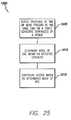
- FIG. 25is a diagram of a touch-based method 1000 .
- the methodbegins at block 1005 where the presence of two or more fingers can be detected on a touch sensitive surface or surfaces of a device at the same time.
- the surface or surfacescan be placed on the device in a manner that allows the detection of gestures, such as a right handed grasp, that would not be easily detected by a small, rectangular touch sensitive surface on a front surface of the device.
- the images of the touch sensitive surface or surfacescan be analyzed to determine data or parameters such as in the manner discussed above.
- the detected contactscan be used to determine the mode of use of the device.
- the mode of usecan be that a right hand has grasped the device.
- the devicecan be configured based on the detected mode of use.
- the user interface of the devicecan be adjusted based on a left hand operation given that the right hand has grasped the device. Configuration can also relate to recalibrating the sensor bias for operations based on a right or left hand operation.
- FIGS. 26A and 26Billustrate a device for implementing the touch-based method 1000 of FIG. 25 .
- FIGS. 26A and 26Billustrate a device 1050 having a plurality of touch sensitive surfaces.
- the touch sensitive surfaceshave been positioned on the device to enable the detection of a set of gestures, such as grasping.
- a touch sensitive display 1075can be positioned on the front surface 1055 of the device 1050
- a touch sensitive strip or pads 1080can be placed on the right surface 1060 of the device 1050 and similar strips or pads (not shown) can be placed on the left surface 1065 and back side 1070 of the device 1050 .
- the placement of these four touch sensitive surfacesallow the detection of a new set of gestures, such as a right hand grasp, that would not be easily detected if the device only had the touch sensitive display 1075 .
- Display 1075can display a number of object or graphical user elements as shown, such as virtual buttons 1085 and 1090 and scroll bar 1095 .
- FIG. 26Ashows device 1050 in its default state where the device is to be held by the left hand.
- scroll bar 1095can be conveniently placed to the right of touch sensitive display 1075 .
- the devicecan have its sensors calibrated for detecting an operation of virtual buttons 1085 and 1090 by fingers of the right hand. This is shown in FIG. 26A by the dotted lines 1086 and 1091 which show a sensor orientation tilted to the left corresponding to a finger operation with the right hand.
- FIG. 26Bshows device 1050 being held by the user's right hand.
- the devicecan detect the presence of the thumb 1096 on touch sensitive strip 1080 on the right surface 1060 of the device 1050 .
- the devicecan also detect at the same time the presence of four fingers 1097 - 1100 on the corresponding touch sensitive strip on the left surface 1065 of the device 1050 . Based on this pattern of touches on the right and left surfaces, device 1050 can determine that the device is being grasped by the right hand and that the mode of use is left handed, given that the fingers of the left hand is free for performing operations.
- Device 1050can be then configured for the left hand mode of use.
- scroll bar 1095can be placed on the left side of display 1075 .
- Thiscan be more convenient for a left hand operation as the user does not have to cross over the display to perform scrolling operations.
- the positions of virtual buttons 1085 and 1090can be also changed to provide for more efficient operations.
- the sensors for detecting an operation of virtual buttons 1085 and 1090can be recalibrated for an operation by the fingers of the left hand. This is shown in FIG. 26B by the dotted lines 1086 and 1091 which show a sensor orientation tilted to the right corresponding to a finger operation with the left hand.
- the memory of the devicecan store a multiple calibrations based on possible gestures such as a right hand grasp. Once the mode of use is determined, the appropriate calibration is quickly retrieved from the device's memory.
- the devicecan be configured to recognize and respond to additional gestures for operating the device once the mode of use is determined by a hand grasping gesture. For example, once it is determined that the right hand is grasping the device 1050 as illustrated in FIG. 26B , the device can be configured so that it recognizes the movement of thumb 1096 along the right surface 1080 . That is, the sensors for the touch sensitive surface 1080 on the left surface 1060 can be recalibrated to detect vertical up and down gestures near where the thumb 1096 is placed as indicated by the arrows in FIG. 26B .
- the recognized gesturecan be used to provide additional operational capability. For example, the up and down gesture of thumb 1096 can act as virtual scroll wheel similar in operation to the displayed scroll 1095 .
- the devicecan be configured to recognize a swipe or touch of the finger on the right side (opposite to edge 1076 ) of the display 1075 as an act of page flipping, similar to how one would hold a small book and flip pages with the left hand.
- the sensors near the right side of the displaycan be calibrated to detect such a gesture and the device operates to change the screen or objects displayed on the screen as if the user is flipping through them.
- FIGS. 26A and 26Bshow segmented touch sensitive surfaces, but the device can have a continuous touch sensitive strip running around a portion of the device or covering the entire device.
- FIGS. 26A-26Brelate to a mode of use based on which hand the device is grasped
- another mode of usecan be orientation.
- the orientation of a devicecan be determined based on detecting how the device is grasped. For example, if the device detects two thumbs being placed near the edge 1076 of display 1075 in FIG. 26A , such data can be used to determine that the user is holding device 1050 along its length as opposed to its width as shown in FIG. 26A .
- the devicecan be configured. For example, virtual buttons 1085 and 1090 and scroll bar 1095 can be rotated to match the new orientation.
- the buttons and scroll barcan also be positioned near the edge 1076 of the display so that the user can easily access them with his thumbs.
- the sensors for the buttons and the scroll barcan be recalibrated to detect either an operation by a finger of the right hand or by a finger of the left hand.
- the new set of gestures enabled by the placement of one or more touch sensitive surfaces on a devicecan be dynamic.
- the usercan pinch the device on two touch sensitive surfaces and spin the device.
- the images of the fingers on the touch sensitive surfacesrotate.
- Touch data based on the rotationcan be used to determine the mode of use, such as pinched rotating grasp, and the device can be configured based on the direction of the rotation of the device and its final orientation.
- Touch sensitive surfacesdo not have to be placed on more than one surface of a device to enable the set of gestures, such as grasping, for configuring the operation of the device.
- Such gesturescan be enabled by placing a single touch sensitive surface along a single surface of the device.
- a touch sensitive surfacecan be wrapped around a lens of a camera, thereby enabling gestures for configuring the operation of the camera and for operating the camera.
- FIG. 27is a diagram of a touch-based method to be implemented with a camera.
- the method 1200begins at block 1205 with a detection of a gesture on a touch sensitive surface on a camera lens.
- the detection of the gesturecan be performed in the manner discussed above. Images of the gesture can be captured and analyzed to detect one or more touches performed on the lens of the camera.
- the camera at block 1210can then generate a signal in accordance with the detected touch.
- the cameracan be then operated at block 1215 based on the generated signal.
- FIGS. 28A-28Dillustrate a sequence and device for implementing method 1200 of FIG. 27 .
- FIGS. 28A-28Dillustrate camera 1250 having lens 1255 .
- a touch sensitive surface 1260can be wrapped around the lens to detect gestures performed on the surface.
- FIG. 28Billustrates the user grasping the lens with his left index finger 1270 and his left thumb 1275 .
- the two-fingered graspcan be used to configure the device, for example, to set the mode of operation relating to exposure.
- the graspcan then be used to operate the camera. For example, if the index finger 1270 is slid forward around the circumference of the lens, the aperture of the camera can open incrementally. If the index finger 1270 is slid backwards around the circumference of the lens, the grasp can be used to close the aperture incrementally.
- FIG. 28Cillustrates the user additionally placing the middle finger 1280 on touch sensitive surface 1260 .
- This three-fingered graspcan be used, for example, to set the mode of operation relating to zooming or focusing.
- any of the gestures described abovecan be used to operate the camera.
- FIG. 28Dshows the middle finger 1280 rolling to the right as indicated by the illustrated arrow. This gesture can perform a telephoto operation with the extension of lens 1285 .
- a roll of middle finger 1280 in the other directioncan be used to perform a wide angle operation.
- the placement of a touch sensitive surface around the lens of a cameracan enable a set of gestures that can be used to configure the operation of the camera and to operate the camera.
- the surfacecan be used to detect a gesture, such as the number of fingers in a grasp, to set or change the mode of operation of the camera. That gesture can be combined with other gestures, such as a rolling gesture of one of the fingers performing the grasp, to operate the camera in that mode. For example, once the zoom mode is set with a three-finger grasp, a roll of one of the three fingers can operate the telephoto and wide angle operation.
- FIG. 29illustrates an exemplary embodiment with a baseball 1300 as part of a video gaming system.
- the baseballcan have a touch sensitive surface 1310 placed on the entire surface of the ball, or part of the surface.
- the surfacecan enable gestures that can be used to configure the operation of the baseball and its use.
- the detection of three fingers on the touch sensitive surfaceincluding fingers 1325 and 1330 at 1315 and 1320 , can be used to indicate to the video gaming system that the ball has been grasped and is ready for use.
- the detection of the two fingers 1325 and 1330can be further analyzed to detect the type of pitch. In this case, the detection of the placement of the knuckles of fingers 1325 and 1330 can be used to signal to the video gaming system that the user has selected a knuckleball.
- a touch sensitive surfacecan be placed on an object.
- the surfacescan be placed on keys or the like to enable gestures relating to the operation of the instrument.
- the term “computer” or “computer system” as recited in the claimsshall be inclusive of at least a desktop computer, a laptop computer, or any mobile computing device such as a mobile communication device (e.g., a cellular or WiFi/Skype phone, e-mail communication devices, personal digital assistant devices), and multimedia reproduction devices (e.g., iPod, MP3 players, or any digital graphics/photo reproducing devices).
- a mobile communication devicee.g., a cellular or WiFi/Skype phone, e-mail communication devices, personal digital assistant devices
- multimedia reproduction devicese.g., iPod, MP3 players, or any digital graphics/photo reproducing devices.
Landscapes
- Engineering & Computer Science (AREA)
- General Engineering & Computer Science (AREA)
- Theoretical Computer Science (AREA)
- Human Computer Interaction (AREA)
- Physics & Mathematics (AREA)
- General Physics & Mathematics (AREA)
- Position Input By Displaying (AREA)
- User Interface Of Digital Computer (AREA)
- Selective Calling Equipment (AREA)
- Details Of Television Systems (AREA)
Abstract
Description
Claims (19)
Priority Applications (5)
| Application Number | Priority Date | Filing Date | Title |
|---|---|---|---|
| US11/818,466US8970503B2 (en) | 2007-01-05 | 2007-06-13 | Gestures for devices having one or more touch sensitive surfaces |
| US11/818,499US8144129B2 (en) | 2007-01-05 | 2007-06-13 | Flexible touch sensing circuits |
| PCT/US2007/089173WO2008085790A2 (en) | 2007-01-05 | 2007-12-28 | Multi-touch skins spanning three dimensions |
| PCT/US2007/089172WO2008085789A2 (en) | 2007-01-05 | 2007-12-28 | Gestures for devices having one or more touch sensitive surfaces |
| US13/372,452US20120139860A1 (en) | 2007-01-05 | 2012-02-13 | Multi-touch skins spanning three dimensions |
Applications Claiming Priority (2)
| Application Number | Priority Date | Filing Date | Title |
|---|---|---|---|
| US87882807P | 2007-01-05 | 2007-01-05 | |
| US11/818,466US8970503B2 (en) | 2007-01-05 | 2007-06-13 | Gestures for devices having one or more touch sensitive surfaces |
Related Child Applications (1)
| Application Number | Title | Priority Date | Filing Date |
|---|---|---|---|
| US11/818,499Continuation-In-PartUS8144129B2 (en) | 2007-01-05 | 2007-06-13 | Flexible touch sensing circuits |
Publications (2)
| Publication Number | Publication Date |
|---|---|
| US20080165255A1 US20080165255A1 (en) | 2008-07-10 |
| US8970503B2true US8970503B2 (en) | 2015-03-03 |
Family
ID=39593922
Family Applications (1)
| Application Number | Title | Priority Date | Filing Date |
|---|---|---|---|
| US11/818,466Expired - Fee RelatedUS8970503B2 (en) | 2007-01-05 | 2007-06-13 | Gestures for devices having one or more touch sensitive surfaces |
Country Status (2)
| Country | Link |
|---|---|
| US (1) | US8970503B2 (en) |
| WO (1) | WO2008085789A2 (en) |
Cited By (9)
| Publication number | Priority date | Publication date | Assignee | Title |
|---|---|---|---|---|
| US20140298171A1 (en)* | 2009-01-16 | 2014-10-02 | Fresenius Medical Care Holdings, Inc. | Methods and apparatus for medical device cursor control and touchpad-based navigation |
| US20150062443A1 (en)* | 2013-09-02 | 2015-03-05 | Samsung Electronics Co., Ltd. | Display apparatus and method for controlling the same |
| US10067569B2 (en) | 2015-08-14 | 2018-09-04 | Fresenius Medical Care Holdings, Inc. | Touchless interface for a medical treatment system |
| US10288881B2 (en) | 2013-03-14 | 2019-05-14 | Fresenius Medical Care Holdings, Inc. | Wearable interface for remote monitoring and control of a medical device |
| US10623188B2 (en) | 2017-04-26 | 2020-04-14 | Fresenius Medical Care Holdings, Inc. | Securely distributing medical prescriptions |
| US10799117B2 (en) | 2009-11-05 | 2020-10-13 | Fresenius Medical Care Holdings, Inc. | Patient treatment and monitoring systems and methods with cause inferencing |
| US11167071B2 (en) | 2015-12-15 | 2021-11-09 | Fresenius Medical Care Deutschland Gmbh | System and method for detecting an operating state or a course of treatment in a blood treatment |
| US11304716B2 (en) | 2015-12-16 | 2022-04-19 | Covidien Lp | Surgical instruments including touch-sensing actuation |
| US11355235B2 (en) | 2011-07-15 | 2022-06-07 | Fresenius Medical Care Deutschland Gmbh | Method and device for remote monitoring and control of medical fluid management devices |
Families Citing this family (150)
| Publication number | Priority date | Publication date | Assignee | Title |
|---|---|---|---|---|
| JP4680918B2 (en) | 2003-05-30 | 2011-05-11 | プリヴァリス・インコーポレーテッド | System and method for assignment and use of media content subscription service privileges |
| US8018440B2 (en) | 2005-12-30 | 2011-09-13 | Microsoft Corporation | Unintentional touch rejection |
| US8144125B2 (en) | 2006-03-30 | 2012-03-27 | Cypress Semiconductor Corporation | Apparatus and method for reducing average scan rate to detect a conductive object on a sensing device |
| US8059015B2 (en) | 2006-05-25 | 2011-11-15 | Cypress Semiconductor Corporation | Capacitance sensing matrix for keyboard architecture |
| US8040321B2 (en) | 2006-07-10 | 2011-10-18 | Cypress Semiconductor Corporation | Touch-sensor with shared capacitive sensors |
| US8970503B2 (en) | 2007-01-05 | 2015-03-03 | Apple Inc. | Gestures for devices having one or more touch sensitive surfaces |
| US8144129B2 (en)* | 2007-01-05 | 2012-03-27 | Apple Inc. | Flexible touch sensing circuits |
| US8058937B2 (en) | 2007-01-30 | 2011-11-15 | Cypress Semiconductor Corporation | Setting a discharge rate and a charge rate of a relaxation oscillator circuit |
| KR101420419B1 (en)* | 2007-04-20 | 2014-07-30 | 엘지전자 주식회사 | Electronic apparatus, data editing method thereof, and mobile communication terminal |
| US8144126B2 (en) | 2007-05-07 | 2012-03-27 | Cypress Semiconductor Corporation | Reducing sleep current in a capacitance sensing system |
| US7936341B2 (en) | 2007-05-30 | 2011-05-03 | Microsoft Corporation | Recognizing selection regions from multiple simultaneous inputs |
| US8258986B2 (en) | 2007-07-03 | 2012-09-04 | Cypress Semiconductor Corporation | Capacitive-matrix keyboard with multiple touch detection |
| KR20200090943A (en) | 2007-09-24 | 2020-07-29 | 애플 인크. | Embedded authentication systems in an electronic device |
| KR101398134B1 (en)* | 2007-10-04 | 2014-05-20 | 엘지전자 주식회사 | Apparatus and method for playing moving-picture in mobile terminal |
| US20090164951A1 (en)* | 2007-12-19 | 2009-06-25 | Nvidia Corporation | Input architecture for devices with small input areas and executing multiple applications |
| US8600120B2 (en) | 2008-01-03 | 2013-12-03 | Apple Inc. | Personal computing device control using face detection and recognition |
| US9024890B2 (en)* | 2008-05-17 | 2015-05-05 | David H. Chin | Comparison of an applied gesture on a touch screen of a mobile device with a remotely stored security gesture |
| US8174503B2 (en) | 2008-05-17 | 2012-05-08 | David H. Cain | Touch-based authentication of a mobile device through user generated pattern creation |
| US20090295545A1 (en)* | 2008-06-03 | 2009-12-03 | O'haire Michael | Method and System for Variable Operation of RFID-Based Readers Utilizing a Trigger Setting |
| US8169414B2 (en)* | 2008-07-12 | 2012-05-01 | Lim Seung E | Control of electronic games via finger angle using a high dimensional touchpad (HDTP) touch user interface |
| JP4632102B2 (en)* | 2008-07-17 | 2011-02-16 | ソニー株式会社 | Information processing apparatus, information processing method, and information processing program |
| US8390577B2 (en)* | 2008-07-25 | 2013-03-05 | Intuilab | Continuous recognition of multi-touch gestures |
| JP4957750B2 (en)* | 2008-07-31 | 2012-06-20 | ソニー株式会社 | Information processing apparatus and method, and program |
| US8347230B2 (en)* | 2008-09-30 | 2013-01-01 | Apple Inc. | Visual presentation of multiple internet pages |
| JP2010097551A (en)* | 2008-10-20 | 2010-04-30 | Panasonic Corp | Portable input device, and input method in portable input device |
| US8466879B2 (en)* | 2008-10-26 | 2013-06-18 | Microsoft Corporation | Multi-touch manipulation of application objects |
| US8477103B2 (en) | 2008-10-26 | 2013-07-02 | Microsoft Corporation | Multi-touch object inertia simulation |
| US8566719B2 (en)* | 2008-11-28 | 2013-10-22 | Creative Technology Ltd | Apparatus and method for controlling a sound reproduction apparatus |
| KR101313218B1 (en)* | 2008-12-08 | 2013-09-30 | 삼성메디슨 주식회사 | Handheld ultrasound system |
| DE102008061988A1 (en)* | 2008-12-12 | 2010-06-17 | Volkswagen Ag | Method and device for displaying information |
| US8330732B2 (en)* | 2008-12-19 | 2012-12-11 | Honeywell International Inc. | Method and apparatus for avionic touchscreen operation providing sensible feedback |
| US8928604B2 (en) | 2008-12-29 | 2015-01-06 | Hewlett-Packard Development Company, L.P. | Gesture detection zones |
| US8365091B2 (en)* | 2009-01-06 | 2013-01-29 | Microsoft Corporation | Non-uniform scrolling |
| KR101617645B1 (en)* | 2009-02-24 | 2016-05-04 | 삼성전자주식회사 | Method for controlling display and apparatus using the same |
| KR101593598B1 (en)* | 2009-04-03 | 2016-02-12 | 삼성전자주식회사 | Method for activating function of portable terminal using user gesture in portable terminal |
| KR101576292B1 (en)* | 2009-05-21 | 2015-12-09 | 엘지전자 주식회사 | The method for executing menu in mobile terminal and mobile terminal using the same |
| KR101167248B1 (en)* | 2009-05-22 | 2012-07-23 | 삼성메디슨 주식회사 | Ultrasound diagonosis apparatus using touch interaction |
| US8836648B2 (en) | 2009-05-27 | 2014-09-16 | Microsoft Corporation | Touch pull-in gesture |
| CN101898042B (en)* | 2009-05-31 | 2012-07-18 | 鸿富锦精密工业(深圳)有限公司 | Game controller and control method thereof |
| US9081492B2 (en)* | 2009-06-15 | 2015-07-14 | Nokia Technologies Oy | Apparatus, method, computer program and user interface |
| JP4843696B2 (en)* | 2009-06-30 | 2011-12-21 | 株式会社東芝 | Information processing apparatus and touch operation support program |
| US8723988B2 (en)* | 2009-07-17 | 2014-05-13 | Sony Corporation | Using a touch sensitive display to control magnification and capture of digital images by an electronic device |
| US20110043461A1 (en)* | 2009-08-24 | 2011-02-24 | Ming-Te Lai | Systems and methods for application management |
| KR20110021062A (en)* | 2009-08-25 | 2011-03-04 | 삼성전자주식회사 | Computer system and its control method |
| US20110074830A1 (en)* | 2009-09-25 | 2011-03-31 | Peter William Rapp | Device, Method, and Graphical User Interface Using Mid-Drag Gestures |
| WO2011037733A1 (en)* | 2009-09-25 | 2011-03-31 | Apple Inc. | Device, method, and graphical user interface using mid-drag gestures |
| US20110074695A1 (en)* | 2009-09-25 | 2011-03-31 | Peter William Rapp | Device, Method, and Graphical User Interface Using Mid-Drag Gestures |
| US20110074696A1 (en)* | 2009-09-25 | 2011-03-31 | Peter William Rapp | Device, Method, and Graphical User Interface Using Mid-Drag Gestures |
| NO332170B1 (en)* | 2009-10-14 | 2012-07-16 | Cisco Systems Int Sarl | Camera control device and method |
| US20110138284A1 (en)* | 2009-12-03 | 2011-06-09 | Microsoft Corporation | Three-state touch input system |
| EP2341418A1 (en)* | 2009-12-31 | 2011-07-06 | Sony Computer Entertainment Europe Limited | Device and method of control |
| US8239785B2 (en)* | 2010-01-27 | 2012-08-07 | Microsoft Corporation | Edge gestures |
| US9411504B2 (en) | 2010-01-28 | 2016-08-09 | Microsoft Technology Licensing, Llc | Copy and staple gestures |
| US8261213B2 (en) | 2010-01-28 | 2012-09-04 | Microsoft Corporation | Brush, carbon-copy, and fill gestures |
| CN102725783B (en)* | 2010-01-29 | 2015-11-25 | 三菱电机株式会社 | Map information processing device |
| US20110191719A1 (en)* | 2010-02-04 | 2011-08-04 | Microsoft Corporation | Cut, Punch-Out, and Rip Gestures |
| US9519356B2 (en) | 2010-02-04 | 2016-12-13 | Microsoft Technology Licensing, Llc | Link gestures |
| US9274682B2 (en)* | 2010-02-19 | 2016-03-01 | Microsoft Technology Licensing, Llc | Off-screen gestures to create on-screen input |
| US8799827B2 (en) | 2010-02-19 | 2014-08-05 | Microsoft Corporation | Page manipulations using on and off-screen gestures |
| US9367205B2 (en) | 2010-02-19 | 2016-06-14 | Microsoft Technolgoy Licensing, Llc | Radial menus with bezel gestures |
| US9310994B2 (en) | 2010-02-19 | 2016-04-12 | Microsoft Technology Licensing, Llc | Use of bezel as an input mechanism |
| US9965165B2 (en) | 2010-02-19 | 2018-05-08 | Microsoft Technology Licensing, Llc | Multi-finger gestures |
| US8707174B2 (en) | 2010-02-25 | 2014-04-22 | Microsoft Corporation | Multi-screen hold and page-flip gesture |
| US8751970B2 (en) | 2010-02-25 | 2014-06-10 | Microsoft Corporation | Multi-screen synchronous slide gesture |
| US8473870B2 (en)* | 2010-02-25 | 2013-06-25 | Microsoft Corporation | Multi-screen hold and drag gesture |
| US8539384B2 (en) | 2010-02-25 | 2013-09-17 | Microsoft Corporation | Multi-screen pinch and expand gestures |
| US9454304B2 (en) | 2010-02-25 | 2016-09-27 | Microsoft Technology Licensing, Llc | Multi-screen dual tap gesture |
| US20110209101A1 (en)* | 2010-02-25 | 2011-08-25 | Hinckley Kenneth P | Multi-screen pinch-to-pocket gesture |
| US9075522B2 (en) | 2010-02-25 | 2015-07-07 | Microsoft Technology Licensing, Llc | Multi-screen bookmark hold gesture |
| US8762893B2 (en) | 2010-05-14 | 2014-06-24 | Google Inc. | Automatic derivation of analogous touch gestures from a user-defined gesture |
| US20110291964A1 (en)* | 2010-06-01 | 2011-12-01 | Kno, Inc. | Apparatus and Method for Gesture Control of a Dual Panel Electronic Device |
| EP2393000B1 (en)* | 2010-06-04 | 2019-08-07 | Lg Electronics Inc. | Mobile terminal capable of providing multiplayer game and method of controlling operation of the mobile terminal |
| US20120019449A1 (en)* | 2010-07-26 | 2012-01-26 | Atmel Corporation | Touch sensing on three dimensional objects |
| CN102346539A (en)* | 2010-07-30 | 2012-02-08 | 技嘉科技股份有限公司 | Motherboards with Energy Saving Features |
| US20120095862A1 (en) | 2010-10-15 | 2012-04-19 | Ness Computing, Inc. (a Delaware Corportaion) | Computer system and method for analyzing data sets and generating personalized recommendations |
| US9396492B2 (en) | 2010-10-15 | 2016-07-19 | Opentable, Inc. | Computer system and method for analyzing data sets and providing personalized recommendations |
| KR101199970B1 (en)* | 2010-10-29 | 2012-11-12 | 전남대학교산학협력단 | Acquisition method of multi-touch feature and multi-touch gesture recognition using the multi-touch feature |
| US8769444B2 (en)* | 2010-11-05 | 2014-07-01 | Sap Ag | Multi-input gesture control for a display screen |
| US20120159395A1 (en) | 2010-12-20 | 2012-06-21 | Microsoft Corporation | Application-launching interface for multiple modes |
| US8689123B2 (en) | 2010-12-23 | 2014-04-01 | Microsoft Corporation | Application reporting in an application-selectable user interface |
| US8612874B2 (en) | 2010-12-23 | 2013-12-17 | Microsoft Corporation | Presenting an application change through a tile |
| KR20120074490A (en)* | 2010-12-28 | 2012-07-06 | 삼성전자주식회사 | Apparatus and method for displaying menu of portable terminal |
| US8509842B2 (en) | 2011-02-18 | 2013-08-13 | Microsoft Corporation | Automatic answering of a mobile phone |
| US9658766B2 (en) | 2011-05-27 | 2017-05-23 | Microsoft Technology Licensing, Llc | Edge gesture |
| US9104440B2 (en) | 2011-05-27 | 2015-08-11 | Microsoft Technology Licensing, Llc | Multi-application environment |
| US9158445B2 (en) | 2011-05-27 | 2015-10-13 | Microsoft Technology Licensing, Llc | Managing an immersive interface in a multi-application immersive environment |
| US9104307B2 (en) | 2011-05-27 | 2015-08-11 | Microsoft Technology Licensing, Llc | Multi-application environment |
| US8893033B2 (en) | 2011-05-27 | 2014-11-18 | Microsoft Corporation | Application notifications |
| US8638385B2 (en) | 2011-06-05 | 2014-01-28 | Apple Inc. | Device, method, and graphical user interface for accessing an application in a locked device |
| US8719719B2 (en)* | 2011-06-17 | 2014-05-06 | Google Inc. | Graphical icon presentation |
| US9417754B2 (en) | 2011-08-05 | 2016-08-16 | P4tents1, LLC | User interface system, method, and computer program product |
| US20130057587A1 (en) | 2011-09-01 | 2013-03-07 | Microsoft Corporation | Arranging tiles |
| US9146670B2 (en) | 2011-09-10 | 2015-09-29 | Microsoft Technology Licensing, Llc | Progressively indicating new content in an application-selectable user interface |
| US20130080898A1 (en)* | 2011-09-26 | 2013-03-28 | Tal Lavian | Systems and methods for electronic communications |
| US9002322B2 (en) | 2011-09-29 | 2015-04-07 | Apple Inc. | Authentication with secondary approver |
| US8769624B2 (en) | 2011-09-29 | 2014-07-01 | Apple Inc. | Access control utilizing indirect authentication |
| US9347791B2 (en)* | 2011-10-07 | 2016-05-24 | The Boeing Company | Methods and systems for operating a touch screen display |
| EP2590065A1 (en) | 2011-11-05 | 2013-05-08 | Johnson Controls Automotive Electronics GmbH | Method for controlling a touch sensitive display device |
| TW201319921A (en)* | 2011-11-07 | 2013-05-16 | Benq Corp | Method for screen control and method for screen display on a touch screen |
| US10082950B2 (en)* | 2011-11-09 | 2018-09-25 | Joseph T. LAPP | Finger-mapped character entry systems |
| US9363441B2 (en) | 2011-12-06 | 2016-06-07 | Musco Corporation | Apparatus, system and method for tracking subject with still or video camera |
| US9008487B2 (en)* | 2011-12-06 | 2015-04-14 | Alcatel Lucent | Spatial bookmarking |
| TWI521424B (en)* | 2011-12-20 | 2016-02-11 | 華碩電腦股份有限公司 | Touch device and touch method |
| DE102011089672A1 (en)* | 2011-12-22 | 2013-06-27 | Siemens Aktiengesellschaft | Operating device for use as capacitive and resistive touch-screen in e.g. hospital information system, has detection unit detecting contacts, where characteristics of contacts are sequentially utilized for evaluating position |
| EP2802967A1 (en)* | 2012-01-09 | 2014-11-19 | Movea | Command of a device by gesture emulation of touch gestures |
| US8436828B1 (en)* | 2012-01-27 | 2013-05-07 | Google Inc. | Smart touchscreen key activation detection |
| US20130194197A1 (en)* | 2012-02-01 | 2013-08-01 | Ideacom Technology Inc. | Electronic Apparatus With Touch Panel and the Operating Method Therefor |
| US9477642B2 (en) | 2012-02-05 | 2016-10-25 | Apple Inc. | Gesture-based navigation among content items |
| CN104115108B (en)* | 2012-02-16 | 2018-07-27 | 古野电气株式会社 | Information display device and display mode switching method |
| JP2013206180A (en)* | 2012-03-28 | 2013-10-07 | Kyocera Corp | Electronic device and display method |
| DE102012103031A1 (en) | 2012-04-05 | 2013-10-10 | Reis Group Holding Gmbh & Co. Kg | Method for operating an industrial robot |
| US9075872B2 (en) | 2012-04-25 | 2015-07-07 | International Business Machines Corporation | Content-based navigation for electronic devices |
| CN111310619B (en) | 2012-05-18 | 2021-06-04 | 苹果公司 | Device, method and graphical user interface for manipulating a user interface |
| US9690465B2 (en) | 2012-06-01 | 2017-06-27 | Microsoft Technology Licensing, Llc | Control of remote applications using companion device |
| US9507513B2 (en) | 2012-08-17 | 2016-11-29 | Google Inc. | Displaced double tap gesture |
| US9582122B2 (en) | 2012-11-12 | 2017-02-28 | Microsoft Technology Licensing, Llc | Touch-sensitive bezel techniques |
| US9497509B2 (en)* | 2012-11-29 | 2016-11-15 | Echostar Uk Holdings Limited | Navigation techniques for electronic programming guides and video |
| US20150339028A1 (en)* | 2012-12-28 | 2015-11-26 | Nokia Technologies Oy | Responding to User Input Gestures |
| TW201433161A (en)* | 2013-02-04 | 2014-08-16 | Hon Hai Prec Ind Co Ltd | Electronic device and method for shooting operation |
| US9053476B2 (en) | 2013-03-15 | 2015-06-09 | Capital One Financial Corporation | Systems and methods for initiating payment from a client device |
| US20140344698A1 (en)* | 2013-05-14 | 2014-11-20 | Sstatzz Oy | System and method for presenting video and information on mobile devices |
| US9552145B2 (en)* | 2013-08-27 | 2017-01-24 | Michael Victor Rodney Foley | System and method for planning tasks based on a graphical representation of time |
| US9898642B2 (en) | 2013-09-09 | 2018-02-20 | Apple Inc. | Device, method, and graphical user interface for manipulating user interfaces based on fingerprint sensor inputs |
| US9477337B2 (en) | 2014-03-14 | 2016-10-25 | Microsoft Technology Licensing, Llc | Conductive trace routing for display and bezel sensors |
| US10043185B2 (en) | 2014-05-29 | 2018-08-07 | Apple Inc. | User interface for payments |
| TWI536202B (en)* | 2014-07-30 | 2016-06-01 | 緯創資通股份有限公司 | Touch device and control method and method for determining unlocking thereof |
| KR20160114413A (en)* | 2015-03-24 | 2016-10-05 | 엘지전자 주식회사 | Mobile terminal and control method for the mobile terminal |
| US10031638B2 (en)* | 2015-02-10 | 2018-07-24 | Etter Studio Ltd. | Multi-touch GUI featuring directional compression and expansion of graphical content |
| US10503392B2 (en)* | 2015-06-25 | 2019-12-10 | Oath Inc. | User interface adjustment methods and systems |
| US9990117B2 (en)* | 2015-08-04 | 2018-06-05 | Lenovo (Singapore) Pte. Ltd. | Zooming and panning within a user interface |
| US10386931B2 (en) | 2016-01-27 | 2019-08-20 | Lenovo (Singapore) Pte. Ltd. | Toggling between presentation and non-presentation of representations of input |
| DK179186B1 (en) | 2016-05-19 | 2018-01-15 | Apple Inc | REMOTE AUTHORIZATION TO CONTINUE WITH AN ACTION |
| DK179978B1 (en) | 2016-09-23 | 2019-11-27 | Apple Inc. | Image data for enhanced user interactions |
| CN106843737B (en)* | 2017-02-13 | 2020-05-08 | 北京新美互通科技有限公司 | Text input method and device and terminal equipment |
| WO2019022739A1 (en)* | 2017-07-27 | 2019-01-31 | Hewlett-Packard Development Company, L.P. | Presenting margin sizes |
| CN117077102A (en) | 2017-09-09 | 2023-11-17 | 苹果公司 | Implementation of biometric authentication |
| KR102185854B1 (en) | 2017-09-09 | 2020-12-02 | 애플 인크. | Implementation of biometric authentication |
| US10645272B2 (en) | 2017-12-04 | 2020-05-05 | Qualcomm Incorporated | Camera zoom level and image frame capture control |
| US10594925B2 (en) | 2017-12-04 | 2020-03-17 | Qualcomm Incorporated | Camera zoom level and image frame capture control |
| US20190196708A1 (en)* | 2017-12-22 | 2019-06-27 | Astro HQ LLC | Camera-detected touch input |
| US11036390B2 (en)* | 2018-05-25 | 2021-06-15 | Mpi Corporation | Display method of display apparatus |
| US11170085B2 (en) | 2018-06-03 | 2021-11-09 | Apple Inc. | Implementation of biometric authentication |
| US10860096B2 (en) | 2018-09-28 | 2020-12-08 | Apple Inc. | Device control using gaze information |
| US11100349B2 (en) | 2018-09-28 | 2021-08-24 | Apple Inc. | Audio assisted enrollment |
| US11023033B2 (en)* | 2019-01-09 | 2021-06-01 | International Business Machines Corporation | Adapting a display of interface elements on a touch-based device to improve visibility |
| DK180318B1 (en) | 2019-04-15 | 2020-11-09 | Apple Inc | Systems, methods, and user interfaces for interacting with multiple application windows |
| US11409410B2 (en) | 2020-09-14 | 2022-08-09 | Apple Inc. | User input interfaces |
| EP4264460A1 (en) | 2021-01-25 | 2023-10-25 | Apple Inc. | Implementation of biometric authentication |
| US12210603B2 (en) | 2021-03-04 | 2025-01-28 | Apple Inc. | User interface for enrolling a biometric feature |
| US12216754B2 (en) | 2021-05-10 | 2025-02-04 | Apple Inc. | User interfaces for authenticating to perform secure operations |
Citations (68)
| Publication number | Priority date | Publication date | Assignee | Title |
|---|---|---|---|---|
| EP0156593A2 (en)* | 1984-03-22 | 1985-10-02 | AMP INCORPORATED (a New Jersey corporation) | Method and apparatus for mode changes and/or touch mouse control |
| US5335557A (en) | 1991-11-26 | 1994-08-09 | Taizo Yasutake | Touch sensitive input control device |
| US5421213A (en) | 1990-10-12 | 1995-06-06 | Okada; Kazuhiro | Multi-dimensional force detector |
| EP0665508A2 (en) | 1993-12-03 | 1995-08-02 | Synaptics, Incorporated | Touch pad driven handheld computing device |
| US5483261A (en) | 1992-02-14 | 1996-01-09 | Itu Research, Inc. | Graphical input controller and method with rear screen image detection |
| US5488204A (en) | 1992-06-08 | 1996-01-30 | Synaptics, Incorporated | Paintbrush stylus for capacitive touch sensor pad |
| US5590219A (en) | 1993-09-30 | 1996-12-31 | Apple Computer, Inc. | Method and apparatus for recognizing gestures on a computer system |
| US5612719A (en) | 1992-12-03 | 1997-03-18 | Apple Computer, Inc. | Gesture sensitive buttons for graphical user interfaces |
| WO1997018547A1 (en) | 1995-11-16 | 1997-05-22 | Ure Michael J | Multi-touch input device, method and system that minimize the need for memorization |
| US5808567A (en) | 1993-05-17 | 1998-09-15 | Dsi Datotech Systems, Inc. | Apparatus and method of communicating using three digits of a hand |
| US5825352A (en) | 1996-01-04 | 1998-10-20 | Logitech, Inc. | Multiple fingers contact sensing method for emulating mouse buttons and mouse operations on a touch sensor pad |
| US5835079A (en) | 1996-06-13 | 1998-11-10 | International Business Machines Corporation | Virtual pointing device for touchscreens |
| US5880411A (en) | 1992-06-08 | 1999-03-09 | Synaptics, Incorporated | Object position detector with edge motion feature and gesture recognition |
| US5942733A (en) | 1992-06-08 | 1999-08-24 | Synaptics, Inc. | Stylus input capacitive touchpad sensor |
| JP2000163031A (en) | 1998-11-25 | 2000-06-16 | Seiko Epson Corp | Portable information devices and information storage media |
| US6188391B1 (en) | 1998-07-09 | 2001-02-13 | Synaptics, Inc. | Two-layer capacitive touchpad and method of making same |
| US6268857B1 (en) | 1997-08-29 | 2001-07-31 | Xerox Corporation | Computer user interface using a physical manipulatory grammar |
| US6278443B1 (en)* | 1998-04-30 | 2001-08-21 | International Business Machines Corporation | Touch screen with random finger placement and rolling on screen to control the movement of information on-screen |
| US6310610B1 (en) | 1997-12-04 | 2001-10-30 | Nortel Networks Limited | Intelligent touch display |
| US6323846B1 (en) | 1998-01-26 | 2001-11-27 | University Of Delaware | Method and apparatus for integrating manual input |
| US6378381B1 (en) | 1999-03-01 | 2002-04-30 | Wacoh Corporation | Sensor using capacitance element |
| US6392636B1 (en)* | 1998-01-22 | 2002-05-21 | Stmicroelectronics, Inc. | Touchpad providing screen cursor/pointer movement control |
| US20020176016A1 (en) | 2001-05-28 | 2002-11-28 | Takeshi Misawa | Portable electronic apparatus |
| JP2002342033A (en) | 2001-05-21 | 2002-11-29 | Sony Corp | Non-contact type user input device |
| US20020190727A1 (en) | 2001-03-14 | 2002-12-19 | Hideo Morimoto | Capacitance type sensor |
| US6597384B1 (en) | 1999-12-22 | 2003-07-22 | Intel Corporation | Automatic reorienting of screen orientation using touch sensitive system |
| US6597347B1 (en) | 1991-11-26 | 2003-07-22 | Itu Research Inc. | Methods and apparatus for providing touch-sensitive input in multiple degrees of freedom |
| US20030137494A1 (en)* | 2000-05-01 | 2003-07-24 | Tulbert David J. | Human-machine interface |
| US20040012579A1 (en)* | 2002-01-31 | 2004-01-22 | Kabushiki Kaisha Tokai-Rika-Denki-Seisakusho | Display screen operation device |
| US6690387B2 (en) | 2001-12-28 | 2004-02-10 | Koninklijke Philips Electronics N.V. | Touch-screen image scrolling system and method |
| US20040055396A1 (en) | 2002-09-24 | 2004-03-25 | Hideo Morimoto | Sensor sheet |
| EP1418491A2 (en) | 2002-10-28 | 2004-05-12 | Delphi Technologies, Inc. | Transparent overlay input device |
| US6750848B1 (en) | 1998-11-09 | 2004-06-15 | Timothy R. Pryor | More useful man machine interfaces and applications |
| WO2004053782A1 (en) | 2002-12-12 | 2004-06-24 | Danfoss A/S | Tactile sensor element and sensor array |
| US20040140984A1 (en)* | 2001-08-29 | 2004-07-22 | Microsoft Corporation | Automatic scrolling |
| EP1445682A2 (en) | 2003-01-22 | 2004-08-11 | Kabushiki Kaisha Toshiba | Electronic apparatus with pointing device on the housing |
| US20040164954A1 (en) | 2003-02-21 | 2004-08-26 | Sony Corporation | Input apparatus, portable electronic device and input method for a portable electronic device |
| WO2004114105A2 (en) | 2003-06-14 | 2004-12-29 | Ronald Peter Binstead | Improvements in touch technology |
| US6950539B2 (en)* | 1998-09-16 | 2005-09-27 | Digital Persona | Configurable multi-function touchpad device |
| US20050264538A1 (en) | 2004-05-25 | 2005-12-01 | I-Hau Yeh | Remote controller |
| WO2005114624A2 (en) | 2004-05-18 | 2005-12-01 | Simon Richard Daniel | Spherical display and control device |
| US20060026535A1 (en) | 2004-07-30 | 2006-02-02 | Apple Computer Inc. | Mode-based graphical user interfaces for touch sensitive input devices |
| WO2006013485A2 (en) | 2004-08-02 | 2006-02-09 | Koninklijke Philips Electronics N.V. | Pressure-controlled navigating in a touch screen |
| US20060044280A1 (en)* | 2004-08-31 | 2006-03-02 | Huddleston Wyatt A | Interface |
| US20060044260A1 (en) | 2004-08-30 | 2006-03-02 | Jonah Harley | Puck-based input device with rotation detection |
| US7015894B2 (en) | 2001-09-28 | 2006-03-21 | Ricoh Company, Ltd. | Information input and output system, method, storage medium, and carrier wave |
| US20060066588A1 (en) | 2004-09-24 | 2006-03-30 | Apple Computer, Inc. | System and method for processing raw data of track pad device |
| US20060097991A1 (en) | 2004-05-06 | 2006-05-11 | Apple Computer, Inc. | Multipoint touchscreen |
| US20060103633A1 (en) | 2004-11-17 | 2006-05-18 | Atrua Technologies, Inc. | Customizable touch input module for an electronic device |
| US20060111093A1 (en) | 2004-11-19 | 2006-05-25 | Samsung Electronics Co., Ltd. | Apparatus and method for controlling portable terminal |
| WO2006075267A2 (en) | 2005-01-14 | 2006-07-20 | Philips Intellectual Property & Standards Gmbh | Moving objects presented by a touch input display device |
| US7084856B2 (en) | 2001-10-22 | 2006-08-01 | Apple Computer, Inc. | Mouse having a rotary dial |
| US20060176270A1 (en) | 2005-02-04 | 2006-08-10 | Sachs Todd S | One dimensional and three dimensional extensions of the slide pad |
| US20060197750A1 (en) | 2005-03-04 | 2006-09-07 | Apple Computer, Inc. | Hand held electronic device with multiple touch sensing devices |
| US20060197753A1 (en) | 2005-03-04 | 2006-09-07 | Hotelling Steven P | Multi-functional hand-held device |
| US20060238517A1 (en) | 2005-03-04 | 2006-10-26 | Apple Computer, Inc. | Electronic Device Having Display and Surrounding Touch Sensitive Bezel for User Interface and Control |
| US20070080953A1 (en)* | 2005-10-07 | 2007-04-12 | Jia-Yih Lii | Method for window movement control on a touchpad having a touch-sense defined speed |
| US20070097096A1 (en)* | 2006-03-25 | 2007-05-03 | Outland Research, Llc | Bimodal user interface paradigm for touch screen devices |
| US20070182722A1 (en) | 2004-08-25 | 2007-08-09 | Hotelling Steven P | Wide touchpad on a portable computer |
| US20070198926A1 (en) | 2004-02-23 | 2007-08-23 | Jazzmutant | Devices and methods of controlling manipulation of virtual objects on a multi-contact tactile screen |
| US20070273658A1 (en)* | 2006-05-26 | 2007-11-29 | Nokia Corporation | Cursor actuation with fingerprint recognition |
| US7312785B2 (en) | 2001-10-22 | 2007-12-25 | Apple Inc. | Method and apparatus for accelerated scrolling |
| US20080042978A1 (en) | 2006-08-18 | 2008-02-21 | Microsoft Corporation | Contact, motion and position sensing circuitry |
| US7345671B2 (en) | 2001-10-22 | 2008-03-18 | Apple Inc. | Method and apparatus for use of rotational user inputs |
| US20080158172A1 (en) | 2007-01-03 | 2008-07-03 | Apple Computer, Inc. | Proximity and multi-touch sensor detection and demodulation |
| WO2008085789A2 (en) | 2007-01-05 | 2008-07-17 | Apple Inc. | Gestures for devices having one or more touch sensitive surfaces |
| WO2008085790A2 (en) | 2007-01-05 | 2008-07-17 | Apple Inc. | Multi-touch skins spanning three dimensions |
| US7694231B2 (en)* | 2006-01-05 | 2010-04-06 | Apple Inc. | Keyboards for portable electronic devices |
Family Cites Families (1)
| Publication number | Priority date | Publication date | Assignee | Title |
|---|---|---|---|---|
| GB2314427B (en)* | 1996-06-21 | 2000-10-18 | British Aerospace | Servomechanisms |
- 2007
- 2007-06-13USUS11/818,466patent/US8970503B2/ennot_activeExpired - Fee Related
- 2007-12-28WOPCT/US2007/089172patent/WO2008085789A2/enactiveApplication Filing
Patent Citations (88)
| Publication number | Priority date | Publication date | Assignee | Title |
|---|---|---|---|---|
| EP0156593A2 (en)* | 1984-03-22 | 1985-10-02 | AMP INCORPORATED (a New Jersey corporation) | Method and apparatus for mode changes and/or touch mouse control |
| US5421213A (en) | 1990-10-12 | 1995-06-06 | Okada; Kazuhiro | Multi-dimensional force detector |
| US6597347B1 (en) | 1991-11-26 | 2003-07-22 | Itu Research Inc. | Methods and apparatus for providing touch-sensitive input in multiple degrees of freedom |
| US5805137A (en) | 1991-11-26 | 1998-09-08 | Itu Research, Inc. | Touch sensitive input control device |
| US5335557A (en) | 1991-11-26 | 1994-08-09 | Taizo Yasutake | Touch sensitive input control device |
| US5483261A (en) | 1992-02-14 | 1996-01-09 | Itu Research, Inc. | Graphical input controller and method with rear screen image detection |
| US5488204A (en) | 1992-06-08 | 1996-01-30 | Synaptics, Incorporated | Paintbrush stylus for capacitive touch sensor pad |
| US5942733A (en) | 1992-06-08 | 1999-08-24 | Synaptics, Inc. | Stylus input capacitive touchpad sensor |
| US5880411A (en) | 1992-06-08 | 1999-03-09 | Synaptics, Incorporated | Object position detector with edge motion feature and gesture recognition |
| US5612719A (en) | 1992-12-03 | 1997-03-18 | Apple Computer, Inc. | Gesture sensitive buttons for graphical user interfaces |
| US5808567A (en) | 1993-05-17 | 1998-09-15 | Dsi Datotech Systems, Inc. | Apparatus and method of communicating using three digits of a hand |
| US5590219A (en) | 1993-09-30 | 1996-12-31 | Apple Computer, Inc. | Method and apparatus for recognizing gestures on a computer system |
| EP0665508A3 (en) | 1993-12-03 | 1997-02-26 | Synaptics Inc | Touch pad driven handheld computing device. |
| EP0665508B1 (en) | 1993-12-03 | 2000-08-16 | Synaptics, Incorporated | Touch pad driven handheld computing device |
| EP0665508A2 (en) | 1993-12-03 | 1995-08-02 | Synaptics, Incorporated | Touch pad driven handheld computing device |
| WO1997018547A1 (en) | 1995-11-16 | 1997-05-22 | Ure Michael J | Multi-touch input device, method and system that minimize the need for memorization |
| US5825352A (en) | 1996-01-04 | 1998-10-20 | Logitech, Inc. | Multiple fingers contact sensing method for emulating mouse buttons and mouse operations on a touch sensor pad |
| US5835079A (en) | 1996-06-13 | 1998-11-10 | International Business Machines Corporation | Virtual pointing device for touchscreens |
| US6268857B1 (en) | 1997-08-29 | 2001-07-31 | Xerox Corporation | Computer user interface using a physical manipulatory grammar |
| US6310610B1 (en) | 1997-12-04 | 2001-10-30 | Nortel Networks Limited | Intelligent touch display |
| US6392636B1 (en)* | 1998-01-22 | 2002-05-21 | Stmicroelectronics, Inc. | Touchpad providing screen cursor/pointer movement control |
| US20050104867A1 (en)* | 1998-01-26 | 2005-05-19 | University Of Delaware | Method and apparatus for integrating manual input |
| US20020015024A1 (en)* | 1998-01-26 | 2002-02-07 | University Of Delaware | Method and apparatus for integrating manual input |
| US6323846B1 (en) | 1998-01-26 | 2001-11-27 | University Of Delaware | Method and apparatus for integrating manual input |
| US20060238522A1 (en) | 1998-01-26 | 2006-10-26 | Fingerworks, Inc. | Identifying contacts on a touch surface |
| US6278443B1 (en)* | 1998-04-30 | 2001-08-21 | International Business Machines Corporation | Touch screen with random finger placement and rolling on screen to control the movement of information on-screen |
| US6188391B1 (en) | 1998-07-09 | 2001-02-13 | Synaptics, Inc. | Two-layer capacitive touchpad and method of making same |
| US6950539B2 (en)* | 1998-09-16 | 2005-09-27 | Digital Persona | Configurable multi-function touchpad device |
| US6750848B1 (en) | 1998-11-09 | 2004-06-15 | Timothy R. Pryor | More useful man machine interfaces and applications |
| JP2000163031A (en) | 1998-11-25 | 2000-06-16 | Seiko Epson Corp | Portable information devices and information storage media |
| US6378381B1 (en) | 1999-03-01 | 2002-04-30 | Wacoh Corporation | Sensor using capacitance element |
| US6597384B1 (en) | 1999-12-22 | 2003-07-22 | Intel Corporation | Automatic reorienting of screen orientation using touch sensitive system |
| US20030137494A1 (en)* | 2000-05-01 | 2003-07-24 | Tulbert David J. | Human-machine interface |
| US20020190727A1 (en) | 2001-03-14 | 2002-12-19 | Hideo Morimoto | Capacitance type sensor |
| JP2002342033A (en) | 2001-05-21 | 2002-11-29 | Sony Corp | Non-contact type user input device |
| US20020176016A1 (en) | 2001-05-28 | 2002-11-28 | Takeshi Misawa | Portable electronic apparatus |
| US20040140984A1 (en)* | 2001-08-29 | 2004-07-22 | Microsoft Corporation | Automatic scrolling |
| US7015894B2 (en) | 2001-09-28 | 2006-03-21 | Ricoh Company, Ltd. | Information input and output system, method, storage medium, and carrier wave |
| US7345671B2 (en) | 2001-10-22 | 2008-03-18 | Apple Inc. | Method and apparatus for use of rotational user inputs |
| US7312785B2 (en) | 2001-10-22 | 2007-12-25 | Apple Inc. | Method and apparatus for accelerated scrolling |
| US7084856B2 (en) | 2001-10-22 | 2006-08-01 | Apple Computer, Inc. | Mouse having a rotary dial |
| US7184064B2 (en) | 2001-12-28 | 2007-02-27 | Koninklijke Philips Electronics N.V. | Touch-screen image scrolling system and method |
| US6690387B2 (en) | 2001-12-28 | 2004-02-10 | Koninklijke Philips Electronics N.V. | Touch-screen image scrolling system and method |
| US20040012579A1 (en)* | 2002-01-31 | 2004-01-22 | Kabushiki Kaisha Tokai-Rika-Denki-Seisakusho | Display screen operation device |
| US20040055396A1 (en) | 2002-09-24 | 2004-03-25 | Hideo Morimoto | Sensor sheet |
| EP1418491A2 (en) | 2002-10-28 | 2004-05-12 | Delphi Technologies, Inc. | Transparent overlay input device |
| EP1418491A3 (en) | 2002-10-28 | 2006-07-19 | Delphi Technologies, Inc. | Transparent overlay input device |
| WO2004053782A1 (en) | 2002-12-12 | 2004-06-24 | Danfoss A/S | Tactile sensor element and sensor array |
| EP1445682A3 (en) | 2003-01-22 | 2006-05-31 | Kabushiki Kaisha Toshiba | Electronic apparatus with pointing device on the housing |
| EP1445682A2 (en) | 2003-01-22 | 2004-08-11 | Kabushiki Kaisha Toshiba | Electronic apparatus with pointing device on the housing |
| US20040164954A1 (en) | 2003-02-21 | 2004-08-26 | Sony Corporation | Input apparatus, portable electronic device and input method for a portable electronic device |
| WO2004114105A3 (en) | 2003-06-14 | 2005-09-15 | Ronald Peter Binstead | Improvements in touch technology |
| WO2004114105A2 (en) | 2003-06-14 | 2004-12-29 | Ronald Peter Binstead | Improvements in touch technology |
| US20070198926A1 (en) | 2004-02-23 | 2007-08-23 | Jazzmutant | Devices and methods of controlling manipulation of virtual objects on a multi-contact tactile screen |
| US20060097991A1 (en) | 2004-05-06 | 2006-05-11 | Apple Computer, Inc. | Multipoint touchscreen |
| US7663607B2 (en) | 2004-05-06 | 2010-02-16 | Apple Inc. | Multipoint touchscreen |
| WO2005114624A2 (en) | 2004-05-18 | 2005-12-01 | Simon Richard Daniel | Spherical display and control device |
| WO2005114624A3 (en) | 2004-05-18 | 2007-04-26 | Simon Richard Daniel | Spherical display and control device |
| US20050264538A1 (en) | 2004-05-25 | 2005-12-01 | I-Hau Yeh | Remote controller |
| US8479122B2 (en) | 2004-07-30 | 2013-07-02 | Apple Inc. | Gestures for touch sensitive input devices |
| US20060026521A1 (en)* | 2004-07-30 | 2006-02-02 | Apple Computer, Inc. | Gestures for touch sensitive input devices |
| US20060026535A1 (en) | 2004-07-30 | 2006-02-02 | Apple Computer Inc. | Mode-based graphical user interfaces for touch sensitive input devices |
| WO2006013485A2 (en) | 2004-08-02 | 2006-02-09 | Koninklijke Philips Electronics N.V. | Pressure-controlled navigating in a touch screen |
| US20070182722A1 (en) | 2004-08-25 | 2007-08-09 | Hotelling Steven P | Wide touchpad on a portable computer |
| US20060044260A1 (en) | 2004-08-30 | 2006-03-02 | Jonah Harley | Puck-based input device with rotation detection |
| US20060044280A1 (en)* | 2004-08-31 | 2006-03-02 | Huddleston Wyatt A | Interface |
| US20060066588A1 (en) | 2004-09-24 | 2006-03-30 | Apple Computer, Inc. | System and method for processing raw data of track pad device |
| US20060103633A1 (en) | 2004-11-17 | 2006-05-18 | Atrua Technologies, Inc. | Customizable touch input module for an electronic device |
| US20060111093A1 (en) | 2004-11-19 | 2006-05-25 | Samsung Electronics Co., Ltd. | Apparatus and method for controlling portable terminal |
| WO2006075267A3 (en) | 2005-01-14 | 2007-04-05 | Philips Intellectual Property | Moving objects presented by a touch input display device |
| WO2006075267A2 (en) | 2005-01-14 | 2006-07-20 | Philips Intellectual Property & Standards Gmbh | Moving objects presented by a touch input display device |
| US20060176270A1 (en) | 2005-02-04 | 2006-08-10 | Sachs Todd S | One dimensional and three dimensional extensions of the slide pad |
| US20060197753A1 (en) | 2005-03-04 | 2006-09-07 | Hotelling Steven P | Multi-functional hand-held device |
| WO2006096501A1 (en) | 2005-03-04 | 2006-09-14 | Apple Computer, Inc. | Hand held electronic device with multiple touch sensing devices |
| US20060238517A1 (en) | 2005-03-04 | 2006-10-26 | Apple Computer, Inc. | Electronic Device Having Display and Surrounding Touch Sensitive Bezel for User Interface and Control |
| US20060197750A1 (en) | 2005-03-04 | 2006-09-07 | Apple Computer, Inc. | Hand held electronic device with multiple touch sensing devices |
| US20070080953A1 (en)* | 2005-10-07 | 2007-04-12 | Jia-Yih Lii | Method for window movement control on a touchpad having a touch-sense defined speed |
| US7694231B2 (en)* | 2006-01-05 | 2010-04-06 | Apple Inc. | Keyboards for portable electronic devices |
| US20070097096A1 (en)* | 2006-03-25 | 2007-05-03 | Outland Research, Llc | Bimodal user interface paradigm for touch screen devices |
| US20070273658A1 (en)* | 2006-05-26 | 2007-11-29 | Nokia Corporation | Cursor actuation with fingerprint recognition |
| US20080042978A1 (en) | 2006-08-18 | 2008-02-21 | Microsoft Corporation | Contact, motion and position sensing circuitry |
| US20080158172A1 (en) | 2007-01-03 | 2008-07-03 | Apple Computer, Inc. | Proximity and multi-touch sensor detection and demodulation |
| WO2008085789A2 (en) | 2007-01-05 | 2008-07-17 | Apple Inc. | Gestures for devices having one or more touch sensitive surfaces |
| WO2008085789A3 (en) | 2007-01-05 | 2009-01-08 | Apple Inc | Gestures for devices having one or more touch sensitive surfaces |
| US20080309634A1 (en) | 2007-01-05 | 2008-12-18 | Apple Inc. | Multi-touch skins spanning three dimensions |
| US8144129B2 (en) | 2007-01-05 | 2012-03-27 | Apple Inc. | Flexible touch sensing circuits |
| US20120139860A1 (en) | 2007-01-05 | 2012-06-07 | Steve Porter Hotelling | Multi-touch skins spanning three dimensions |
| WO2008085790A2 (en) | 2007-01-05 | 2008-07-17 | Apple Inc. | Multi-touch skins spanning three dimensions |
Non-Patent Citations (25)
| Title |
|---|
| Anonymous. (2008). NoviiRemote Deluxe Review from The Gadgeteer.com located at , last visited May 8, 2008, six pages. |
| Anonymous. (2008). NoviiRemote Deluxe Review from The Gadgeteer.com located at <http://www.novii.tv/news/article//allarticle/article5/ . . . >, last visited May 8, 2008, six pages. |
| Anonymous. (Feb. 21, 2008). "Apple iPhone Trackpad Turns into PC Remote Control," Video Review located at <http://www.phonesreview.co.uk/2008/02/21/video-apple-iphone-trackpad-turns-into-pc-remote-control-download-it-now . . . >, last visited Apr. 18, 2008, three pages. |
| D. Rubine, et al., "Programmable Finger-tracking Instrument Controllers," Computer Music Journal, vol. 14, No, 1, Spring 1990. |
| Final Office Action mailed Sep. 7, 2012, for U.S. Appl. No. 13/372,452, filed Feb. 13, 2012, 14 pages. |
| Hromadka, J. (Jul. 6, 2005). "NoviiRemote Blaster," Treocentral.com, located at , last visited May 8, 2008, three pages. |
| Hromadka, J. (Jul. 6, 2005). "NoviiRemote Blaster," Treocentral.com, located at <http://www.treocentral.com/content/Stories/630-1.html>, last visited May 8, 2008, three pages. |
| Iftode, L. et al. (2008). "Smart Phone: An Embedded System for Universal Interactions," Rutger's University, Department of Computer Science, seven pages. |
| International Search Report mailed Mar. 30, 2009, for PCT Application No. PCT/US2007/089173, filed Dec. 28, 2007, nine pages. |
| International Search Report mailed Nov. 26, 2008, for PCT Application No. PCT/US2007/089172, filed Dec. 28, 2007, six pages. |
| Izadi, S. et al. (2007). "C-Slate: A Multi-Touch and Object Recognition System for Remote Collaboration using Horizontal Surfaces," Microsoft Research-Cambridge, eight pages. |
| J. Rekimoto, "SmartSkin: An Infrastructure for Freehand Manipulation on Interactive Surfaces," Computer Human Interaction, 2002. |
| J. Rekimoto, et al., ToolStone: Effective Use of the Physical Manipulation Vocabularies of Input Devices, UIST 2000, pp. 109-117. |
| Lee, S.K. et al. (Apr. 1985). "A Multi-Touch Three Dimensional Touch-Sensitive Tablet," Proceedings of CHI: ACM Conference on Human Factors in Computing Systems, pp. 21-25. |
| M. Fukumoto, et al., "Body Coupled FingeRing: Wireless Wearable Keyboard," Computer Human Interaction, 1997. |
| Non-Final Office Action mailed Apr. 16, 2014, for U.S. Appl. No. 13/372,452, filed Feb. 13, 2012, 15 pages. |
| Non-Final Office Action mailed Apr. 5, 2012, for U.S. Appl. No. 13/372,452, filed Feb. 13, 2012, four pages. |
| Non-Final Office Action mailed Feb. 16, 2011, for U.S. Appl. No. 11/818,499, filed Jun. 13, 2007, 12 pages. |
| Notice of Allowance mailed Oct. 18, 2011, for U.S. Appl. No. 11/818,499, 7 pages. |
| P. Dietz, et al., "DiamondTouch: A Multi-User Touch Technology," UIST 2001, pp. 219-226. |
| Rubine, D.H. (Dec. 1991). "The Automatic Recognition of Gestures," CMU-CS-91-202, Submitted in Partial Fulfillment of the Requirements of the Degree of Doctor of Philosophy in Computer Science at Carnegie Mellon University, 285 pages. |
| Rubine, D.H. (May 1992). "Combining Gestures and Direct Manipulation," CHI ' 92, pp. 659-660. |
| Sellers, D. (Mar. 2, 2006). "Apple Files New Patent for Wide Touchpad for Notebooks," Macsimum News, located at <http://www.macsimumnews.com/index.php/archive/apple-files-new-patent-for-wide-touchpad-for-notebooks/>, last visited Apr. 11, 2008, 11 pages. |
| Webb, W. (Jan. 10, 2005), "Smart Phones: The Next Embedded Interface," Forbes.com, located at <http/:www.forbes.com/technology/wireless/feeds/wireless/2005/01...005-01-10-eng-cahners-eng-cahners-084514-7136474990124214945.html>, last visited May 8, 2008, six pages. |
| Westerman, W. (Spring 1999). "Hand Tracking, Finger Identification, and Chordic Manipulation on a Multi-Touch Surface," A Dissertation Submitted to the Faculty of the University of Delaware in Partial Fulfillment of the Requirements for the Degree of Doctor of Philosophy in Electrical Engineering, 364 pages. |
Cited By (17)
| Publication number | Priority date | Publication date | Assignee | Title |
|---|---|---|---|---|
| US10824326B2 (en) | 2009-01-16 | 2020-11-03 | Fresenius Medical Care Holdings, Inc. | Remote interfacing with a networked dialysis system |
| US20140298171A1 (en)* | 2009-01-16 | 2014-10-02 | Fresenius Medical Care Holdings, Inc. | Methods and apparatus for medical device cursor control and touchpad-based navigation |
| US10078438B2 (en)* | 2009-01-16 | 2018-09-18 | Fresenius Care Holdings, Inc. | Methods and apparatus for medical device cursor control and touchpad-based navigation |
| US11481105B2 (en) | 2009-01-16 | 2022-10-25 | Fresenius Medical Care Holdings, Inc. | Remote interfacing with a networked dialysis system |
| US10799117B2 (en) | 2009-11-05 | 2020-10-13 | Fresenius Medical Care Holdings, Inc. | Patient treatment and monitoring systems and methods with cause inferencing |
| US12260958B2 (en) | 2011-07-15 | 2025-03-25 | Fresenius Medical Care Deutschland Gmbh | Method and device for remote monitoring and control of medical fluid management devices |
| US11869660B2 (en) | 2011-07-15 | 2024-01-09 | Fresenius Medical Care Deutschland Gmbh | Method and device for remote monitoring and control of medical fluid management devices |
| US11355235B2 (en) | 2011-07-15 | 2022-06-07 | Fresenius Medical Care Deutschland Gmbh | Method and device for remote monitoring and control of medical fluid management devices |
| US10288881B2 (en) | 2013-03-14 | 2019-05-14 | Fresenius Medical Care Holdings, Inc. | Wearable interface for remote monitoring and control of a medical device |
| US20150062443A1 (en)* | 2013-09-02 | 2015-03-05 | Samsung Electronics Co., Ltd. | Display apparatus and method for controlling the same |
| US9654720B2 (en)* | 2013-09-02 | 2017-05-16 | Samsung Electronics Co., Ltd. | Display apparatus and method for controlling the same |
| US10067569B2 (en) | 2015-08-14 | 2018-09-04 | Fresenius Medical Care Holdings, Inc. | Touchless interface for a medical treatment system |
| US11167071B2 (en) | 2015-12-15 | 2021-11-09 | Fresenius Medical Care Deutschland Gmbh | System and method for detecting an operating state or a course of treatment in a blood treatment |
| US11304716B2 (en) | 2015-12-16 | 2022-04-19 | Covidien Lp | Surgical instruments including touch-sensing actuation |
| US10623188B2 (en) | 2017-04-26 | 2020-04-14 | Fresenius Medical Care Holdings, Inc. | Securely distributing medical prescriptions |
| US11424934B2 (en) | 2017-04-26 | 2022-08-23 | Fresenius Medical Care Holdings, Inc. | Securely distributing medical prescriptions |
| US12101414B2 (en) | 2017-04-26 | 2024-09-24 | Fresenius Medical Care Holdings, Inc. | Securely distributing medical prescriptions |
Also Published As
| Publication number | Publication date |
|---|---|
| WO2008085789A3 (en) | 2009-01-08 |
| US20080165255A1 (en) | 2008-07-10 |
| WO2008085789A2 (en) | 2008-07-17 |
Similar Documents
| Publication | Publication Date | Title |
|---|---|---|
| US8970503B2 (en) | Gestures for devices having one or more touch sensitive surfaces | |
| US8686962B2 (en) | Gestures for controlling, manipulating, and editing of media files using touch sensitive devices | |
| CN101611373B (en) | Gestures for controlling, manipulating and editing media files with touch-sensitive devices | |
| US7924271B2 (en) | Detecting gestures on multi-event sensitive devices | |
| US7877707B2 (en) | Detecting and interpreting real-world and security gestures on touch and hover sensitive devices | |
| US9348458B2 (en) | Gestures for touch sensitive input devices | |
| EP1774429B1 (en) | Gestures for touch sensitive input devices | |
| AU2011253700B2 (en) | Gestures for controlling, manipulating, and editing of media files using touch sensitive devices | |
| HK1120135A (en) | Multimedia communication device with touch screen responsive to gestures for controlling, manipulating and editing of media files | |
| HK1194171A (en) | Gestures for controlling, manipulating, and editing of media files using touch sensitive devices | |
| HK1194171B (en) | Gestures for controlling, manipulating, and editing of media files using touch sensitive devices | |
| HK1103143A (en) | Gestures for touch sensitive input devices | |
| HK1103143B (en) | Gestures for touch sensitive input devices |
Legal Events
| Date | Code | Title | Description |
|---|---|---|---|
| AS | Assignment | Owner name:APPLE INC., CALIFORNIA Free format text:ASSIGNMENT OF ASSIGNORS INTEREST;ASSIGNORS:CHRISTIE, GREG;WESTERMAN, WAYNE CARL;REEL/FRAME:019494/0621;SIGNING DATES FROM 20070525 TO 20070613 Owner name:APPLE INC., CALIFORNIA Free format text:ASSIGNMENT OF ASSIGNORS INTEREST;ASSIGNORS:CHRISTIE, GREG;WESTERMAN, WAYNE CARL;SIGNING DATES FROM 20070525 TO 20070613;REEL/FRAME:019494/0621 | |
| AS | Assignment | Owner name:APPLE INC., CALIFORNIA Free format text:CORRECTIVE ASSIGNMENT TO CORRECT THE ASSIGNEE'S STATE OF INCORPORATION AS IT APPEARS IN THE BODY OF THE DOCUMENT PREVIOUSLY RECORDED ON REEL 019494, FRAME 0621. ASSIGNORS HEREBY CONFIRM THE ASSIGNMENT OF THE ENTIRE INTEREST.;ASSIGNORS:CHRISTIE, GREG;WESTERMAN, WAYNE CARL;REEL/FRAME:020441/0483;SIGNING DATES FROM 20070525 TO 20070613 Owner name:APPLE INC., CALIFORNIA Free format text:CORRECTIVE ASSIGNMENT TO CORRECT THE ASSIGNEE'S STATE OF INCORPORATION AS IT APPEARS IN THE BODY OF THE DOCUMENT PREVIOUSLY RECORDED ON REEL 019494, FRAME 0621. ASSIGNORS HEREBY CONFIRM THE ASSIGNMENT OF THE ENTIRE INTEREST;ASSIGNORS:CHRISTIE, GREG;WESTERMAN, WAYNE CARL;SIGNING DATES FROM 20070525 TO 20070613;REEL/FRAME:020441/0483 | |
| FEPP | Fee payment procedure | Free format text:PAYOR NUMBER ASSIGNED (ORIGINAL EVENT CODE: ASPN); ENTITY STATUS OF PATENT OWNER: LARGE ENTITY | |
| STCF | Information on status: patent grant | Free format text:PATENTED CASE | |
| MAFP | Maintenance fee payment | Free format text:PAYMENT OF MAINTENANCE FEE, 4TH YEAR, LARGE ENTITY (ORIGINAL EVENT CODE: M1551); ENTITY STATUS OF PATENT OWNER: LARGE ENTITY Year of fee payment:4 | |
| FEPP | Fee payment procedure | Free format text:MAINTENANCE FEE REMINDER MAILED (ORIGINAL EVENT CODE: REM.); ENTITY STATUS OF PATENT OWNER: LARGE ENTITY | |
| LAPS | Lapse for failure to pay maintenance fees | Free format text:PATENT EXPIRED FOR FAILURE TO PAY MAINTENANCE FEES (ORIGINAL EVENT CODE: EXP.); ENTITY STATUS OF PATENT OWNER: LARGE ENTITY | |
| STCH | Information on status: patent discontinuation | Free format text:PATENT EXPIRED DUE TO NONPAYMENT OF MAINTENANCE FEES UNDER 37 CFR 1.362 | |
| FP | Lapsed due to failure to pay maintenance fee | Effective date:20230303 |