US8970438B2 - Method of providing an antenna mast and an antenna mast system - Google Patents
Method of providing an antenna mast and an antenna mast systemDownload PDFInfo
- Publication number
- US8970438B2 US8970438B2US13/025,531US201113025531AUS8970438B2US 8970438 B2US8970438 B2US 8970438B2US 201113025531 AUS201113025531 AUS 201113025531AUS 8970438 B2US8970438 B2US 8970438B2
- Authority
- US
- United States
- Prior art keywords
- modules
- module
- mast
- different kinds
- antenna
- Prior art date
- Legal status (The legal status is an assumption and is not a legal conclusion. Google has not performed a legal analysis and makes no representation as to the accuracy of the status listed.)
- Active, expires
Links
- 238000000034methodMethods0.000titleclaimsabstractdescription59
- 238000004891communicationMethods0.000claimsabstractdescription68
- 238000004519manufacturing processMethods0.000claimsdescription9
- 239000002699waste materialSubstances0.000claimsdescription8
- 239000000203mixtureSubstances0.000description3
- 238000010295mobile communicationMethods0.000description3
- 238000001556precipitationMethods0.000description3
- 230000006978adaptationEffects0.000description2
- 238000009434installationMethods0.000description2
- 229920002430Fibre-reinforced plasticPolymers0.000description1
- 229910000831SteelInorganic materials0.000description1
- QVGXLLKOCUKJST-UHFFFAOYSA-Natomic oxygenChemical compound[O]QVGXLLKOCUKJST-UHFFFAOYSA-N0.000description1
- 230000005540biological transmissionEffects0.000description1
- 238000010276constructionMethods0.000description1
- 238000005516engineering processMethods0.000description1
- 239000003365glass fiberSubstances0.000description1
- 230000007774longtermEffects0.000description1
- 239000000463materialSubstances0.000description1
- 238000012986modificationMethods0.000description1
- 230000004048modificationEffects0.000description1
- 238000012544monitoring processMethods0.000description1
- 229910052760oxygenInorganic materials0.000description1
- 239000001301oxygenSubstances0.000description1
- 239000004033plasticSubstances0.000description1
- 229920003023plasticPolymers0.000description1
- 239000010959steelSubstances0.000description1
- XLYOFNOQVPJJNP-UHFFFAOYSA-NwaterSubstancesOXLYOFNOQVPJJNP-UHFFFAOYSA-N0.000description1
Images


Classifications
- H—ELECTRICITY
- H01—ELECTRIC ELEMENTS
- H01Q—ANTENNAS, i.e. RADIO AERIALS
- H01Q1/00—Details of, or arrangements associated with, antennas
- H01Q1/44—Details of, or arrangements associated with, antennas using equipment having another main function to serve additionally as an antenna, e.g. means for giving an antenna an aesthetic aspect
- B60L11/1816—
- B60L11/1825—
- B—PERFORMING OPERATIONS; TRANSPORTING
- B60—VEHICLES IN GENERAL
- B60L—PROPULSION OF ELECTRICALLY-PROPELLED VEHICLES; SUPPLYING ELECTRIC POWER FOR AUXILIARY EQUIPMENT OF ELECTRICALLY-PROPELLED VEHICLES; ELECTRODYNAMIC BRAKE SYSTEMS FOR VEHICLES IN GENERAL; MAGNETIC SUSPENSION OR LEVITATION FOR VEHICLES; MONITORING OPERATING VARIABLES OF ELECTRICALLY-PROPELLED VEHICLES; ELECTRIC SAFETY DEVICES FOR ELECTRICALLY-PROPELLED VEHICLES
- B60L53/00—Methods of charging batteries, specially adapted for electric vehicles; Charging stations or on-board charging equipment therefor; Exchange of energy storage elements in electric vehicles
- B60L53/10—Methods of charging batteries, specially adapted for electric vehicles; Charging stations or on-board charging equipment therefor; Exchange of energy storage elements in electric vehicles characterised by the energy transfer between the charging station and the vehicle
- B60L53/14—Conductive energy transfer
- B—PERFORMING OPERATIONS; TRANSPORTING
- B60—VEHICLES IN GENERAL
- B60L—PROPULSION OF ELECTRICALLY-PROPELLED VEHICLES; SUPPLYING ELECTRIC POWER FOR AUXILIARY EQUIPMENT OF ELECTRICALLY-PROPELLED VEHICLES; ELECTRODYNAMIC BRAKE SYSTEMS FOR VEHICLES IN GENERAL; MAGNETIC SUSPENSION OR LEVITATION FOR VEHICLES; MONITORING OPERATING VARIABLES OF ELECTRICALLY-PROPELLED VEHICLES; ELECTRIC SAFETY DEVICES FOR ELECTRICALLY-PROPELLED VEHICLES
- B60L53/00—Methods of charging batteries, specially adapted for electric vehicles; Charging stations or on-board charging equipment therefor; Exchange of energy storage elements in electric vehicles
- B60L53/30—Constructional details of charging stations
- B60L53/305—Communication interfaces
- B—PERFORMING OPERATIONS; TRANSPORTING
- B60—VEHICLES IN GENERAL
- B60L—PROPULSION OF ELECTRICALLY-PROPELLED VEHICLES; SUPPLYING ELECTRIC POWER FOR AUXILIARY EQUIPMENT OF ELECTRICALLY-PROPELLED VEHICLES; ELECTRODYNAMIC BRAKE SYSTEMS FOR VEHICLES IN GENERAL; MAGNETIC SUSPENSION OR LEVITATION FOR VEHICLES; MONITORING OPERATING VARIABLES OF ELECTRICALLY-PROPELLED VEHICLES; ELECTRIC SAFETY DEVICES FOR ELECTRICALLY-PROPELLED VEHICLES
- B60L53/00—Methods of charging batteries, specially adapted for electric vehicles; Charging stations or on-board charging equipment therefor; Exchange of energy storage elements in electric vehicles
- B60L53/30—Constructional details of charging stations
- B60L53/31—Charging columns specially adapted for electric vehicles
- B—PERFORMING OPERATIONS; TRANSPORTING
- B60—VEHICLES IN GENERAL
- B60L—PROPULSION OF ELECTRICALLY-PROPELLED VEHICLES; SUPPLYING ELECTRIC POWER FOR AUXILIARY EQUIPMENT OF ELECTRICALLY-PROPELLED VEHICLES; ELECTRODYNAMIC BRAKE SYSTEMS FOR VEHICLES IN GENERAL; MAGNETIC SUSPENSION OR LEVITATION FOR VEHICLES; MONITORING OPERATING VARIABLES OF ELECTRICALLY-PROPELLED VEHICLES; ELECTRIC SAFETY DEVICES FOR ELECTRICALLY-PROPELLED VEHICLES
- B60L53/00—Methods of charging batteries, specially adapted for electric vehicles; Charging stations or on-board charging equipment therefor; Exchange of energy storage elements in electric vehicles
- B60L53/60—Monitoring or controlling charging stations
- B60L53/68—Off-site monitoring or control, e.g. remote control
- H—ELECTRICITY
- H01—ELECTRIC ELEMENTS
- H01Q—ANTENNAS, i.e. RADIO AERIALS
- H01Q1/00—Details of, or arrangements associated with, antennas
- H01Q1/12—Supports; Mounting means
- H01Q1/1242—Rigid masts specially adapted for supporting an aerial
- H—ELECTRICITY
- H01—ELECTRIC ELEMENTS
- H01Q—ANTENNAS, i.e. RADIO AERIALS
- H01Q1/00—Details of, or arrangements associated with, antennas
- H01Q1/12—Supports; Mounting means
- H01Q1/22—Supports; Mounting means by structural association with other equipment or articles
- H01Q1/24—Supports; Mounting means by structural association with other equipment or articles with receiving set
- H01Q1/241—Supports; Mounting means by structural association with other equipment or articles with receiving set used in mobile communications, e.g. GSM
- H01Q1/246—Supports; Mounting means by structural association with other equipment or articles with receiving set used in mobile communications, e.g. GSM specially adapted for base stations
- B60L2230/16—
- B60L2230/40—
- Y—GENERAL TAGGING OF NEW TECHNOLOGICAL DEVELOPMENTS; GENERAL TAGGING OF CROSS-SECTIONAL TECHNOLOGIES SPANNING OVER SEVERAL SECTIONS OF THE IPC; TECHNICAL SUBJECTS COVERED BY FORMER USPC CROSS-REFERENCE ART COLLECTIONS [XRACs] AND DIGESTS
- Y02—TECHNOLOGIES OR APPLICATIONS FOR MITIGATION OR ADAPTATION AGAINST CLIMATE CHANGE
- Y02T—CLIMATE CHANGE MITIGATION TECHNOLOGIES RELATED TO TRANSPORTATION
- Y02T10/00—Road transport of goods or passengers
- Y02T10/60—Other road transportation technologies with climate change mitigation effect
- Y02T10/70—Energy storage systems for electromobility, e.g. batteries
- Y02T10/7005—
- Y—GENERAL TAGGING OF NEW TECHNOLOGICAL DEVELOPMENTS; GENERAL TAGGING OF CROSS-SECTIONAL TECHNOLOGIES SPANNING OVER SEVERAL SECTIONS OF THE IPC; TECHNICAL SUBJECTS COVERED BY FORMER USPC CROSS-REFERENCE ART COLLECTIONS [XRACs] AND DIGESTS
- Y02—TECHNOLOGIES OR APPLICATIONS FOR MITIGATION OR ADAPTATION AGAINST CLIMATE CHANGE
- Y02T—CLIMATE CHANGE MITIGATION TECHNOLOGIES RELATED TO TRANSPORTATION
- Y02T10/00—Road transport of goods or passengers
- Y02T10/60—Other road transportation technologies with climate change mitigation effect
- Y02T10/7072—Electromobility specific charging systems or methods for batteries, ultracapacitors, supercapacitors or double-layer capacitors
- Y02T10/7088—
- Y—GENERAL TAGGING OF NEW TECHNOLOGICAL DEVELOPMENTS; GENERAL TAGGING OF CROSS-SECTIONAL TECHNOLOGIES SPANNING OVER SEVERAL SECTIONS OF THE IPC; TECHNICAL SUBJECTS COVERED BY FORMER USPC CROSS-REFERENCE ART COLLECTIONS [XRACs] AND DIGESTS
- Y02—TECHNOLOGIES OR APPLICATIONS FOR MITIGATION OR ADAPTATION AGAINST CLIMATE CHANGE
- Y02T—CLIMATE CHANGE MITIGATION TECHNOLOGIES RELATED TO TRANSPORTATION
- Y02T90/00—Enabling technologies or technologies with a potential or indirect contribution to GHG emissions mitigation
- Y02T90/10—Technologies relating to charging of electric vehicles
- Y02T90/12—Electric charging stations
- Y02T90/121—
- Y02T90/128—
- Y—GENERAL TAGGING OF NEW TECHNOLOGICAL DEVELOPMENTS; GENERAL TAGGING OF CROSS-SECTIONAL TECHNOLOGIES SPANNING OVER SEVERAL SECTIONS OF THE IPC; TECHNICAL SUBJECTS COVERED BY FORMER USPC CROSS-REFERENCE ART COLLECTIONS [XRACs] AND DIGESTS
- Y02—TECHNOLOGIES OR APPLICATIONS FOR MITIGATION OR ADAPTATION AGAINST CLIMATE CHANGE
- Y02T—CLIMATE CHANGE MITIGATION TECHNOLOGIES RELATED TO TRANSPORTATION
- Y02T90/00—Enabling technologies or technologies with a potential or indirect contribution to GHG emissions mitigation
- Y02T90/10—Technologies relating to charging of electric vehicles
- Y02T90/14—Plug-in electric vehicles
- Y—GENERAL TAGGING OF NEW TECHNOLOGICAL DEVELOPMENTS; GENERAL TAGGING OF CROSS-SECTIONAL TECHNOLOGIES SPANNING OVER SEVERAL SECTIONS OF THE IPC; TECHNICAL SUBJECTS COVERED BY FORMER USPC CROSS-REFERENCE ART COLLECTIONS [XRACs] AND DIGESTS
- Y02—TECHNOLOGIES OR APPLICATIONS FOR MITIGATION OR ADAPTATION AGAINST CLIMATE CHANGE
- Y02T—CLIMATE CHANGE MITIGATION TECHNOLOGIES RELATED TO TRANSPORTATION
- Y02T90/00—Enabling technologies or technologies with a potential or indirect contribution to GHG emissions mitigation
- Y02T90/10—Technologies relating to charging of electric vehicles
- Y02T90/16—Information or communication technologies improving the operation of electric vehicles
- Y02T90/163—
- Y—GENERAL TAGGING OF NEW TECHNOLOGICAL DEVELOPMENTS; GENERAL TAGGING OF CROSS-SECTIONAL TECHNOLOGIES SPANNING OVER SEVERAL SECTIONS OF THE IPC; TECHNICAL SUBJECTS COVERED BY FORMER USPC CROSS-REFERENCE ART COLLECTIONS [XRACs] AND DIGESTS
- Y02—TECHNOLOGIES OR APPLICATIONS FOR MITIGATION OR ADAPTATION AGAINST CLIMATE CHANGE
- Y02T—CLIMATE CHANGE MITIGATION TECHNOLOGIES RELATED TO TRANSPORTATION
- Y02T90/00—Enabling technologies or technologies with a potential or indirect contribution to GHG emissions mitigation
- Y02T90/10—Technologies relating to charging of electric vehicles
- Y02T90/16—Information or communication technologies improving the operation of electric vehicles
- Y02T90/167—Systems integrating technologies related to power network operation and communication or information technologies for supporting the interoperability of electric or hybrid vehicles, i.e. smartgrids as interface for battery charging of electric vehicles [EV] or hybrid vehicles [HEV]
- Y02T90/168—
- Y—GENERAL TAGGING OF NEW TECHNOLOGICAL DEVELOPMENTS; GENERAL TAGGING OF CROSS-SECTIONAL TECHNOLOGIES SPANNING OVER SEVERAL SECTIONS OF THE IPC; TECHNICAL SUBJECTS COVERED BY FORMER USPC CROSS-REFERENCE ART COLLECTIONS [XRACs] AND DIGESTS
- Y04—INFORMATION OR COMMUNICATION TECHNOLOGIES HAVING AN IMPACT ON OTHER TECHNOLOGY AREAS
- Y04S—SYSTEMS INTEGRATING TECHNOLOGIES RELATED TO POWER NETWORK OPERATION, COMMUNICATION OR INFORMATION TECHNOLOGIES FOR IMPROVING THE ELECTRICAL POWER GENERATION, TRANSMISSION, DISTRIBUTION, MANAGEMENT OR USAGE, i.e. SMART GRIDS
- Y04S30/00—Systems supporting specific end-user applications in the sector of transportation
- Y04S30/10—Systems supporting the interoperability of electric or hybrid vehicles
- Y04S30/12—Remote or cooperative charging
- Y—GENERAL TAGGING OF NEW TECHNOLOGICAL DEVELOPMENTS; GENERAL TAGGING OF CROSS-SECTIONAL TECHNOLOGIES SPANNING OVER SEVERAL SECTIONS OF THE IPC; TECHNICAL SUBJECTS COVERED BY FORMER USPC CROSS-REFERENCE ART COLLECTIONS [XRACs] AND DIGESTS
- Y10—TECHNICAL SUBJECTS COVERED BY FORMER USPC
- Y10T—TECHNICAL SUBJECTS COVERED BY FORMER US CLASSIFICATION
- Y10T29/00—Metal working
- Y10T29/49—Method of mechanical manufacture
- Y10T29/49002—Electrical device making
- Y10T29/49016—Antenna or wave energy "plumbing" making
Definitions
- the technical field concernedrelates to a method of providing an antenna mast for a wireless communication system and a modular antenna mast system for providing antenna masts of a wireless communication system.
- Wireless communication systems using radio communicationcomprise transceiver arrangements and processors comprised in what may be referred to as base stations, radio network controllers, or node B's. Furthermore, antennas are connected to the transceiver arrangements and are required for transmitting and receiving radio signals. The antennas may for instance be arranged on an antenna mast. A variety of masts have been suggested in the prior art but in practice a steel lattice mast is the most common type of mast used.
- Wireless communicationsuch as mobile internet access by means of mobile communication equipment is demanded by more people and more devices.
- radio traffic within the wireless communication systemsincreases and so does the required number of access points for the mobile communication equipment.
- For each access pointat least one antenna is required and thus the number of antennas that are required increases with the increased demand in mobile internet access.
- EP1198024discloses an antenna mast wherein an antenna is raised and lowered along a guiding means inside the antenna mast.
- the antenna mastcomprises a carrying pipe for a lamp.
- U.S. Pat. No. 6,335,709discloses a service tower integrating a water tank and an antenna mast in a single structure.
- EP1286412discloses a radio tower with a central supporting tower structure comprising several modules of the same outer shape being arranged one above the other.
- the moduleshouse for instance transmission and power supply equipment.
- the towercomprises stiff ring-shaped portions of covering made from glass fibre reinforced plastic material, inside which the modules of the radio tower are arranged.
- Each ring-shaped coveringis supported by a module of the radio tower.
- screens for providing information or announcementsmay be arranged.
- the use of the covering for housing small shops or ticket machinesis suggested.
- WO98/58420discloses a wireless communication pole system.
- the systemis fully integrated for rapid installation.
- the systemcomprises a pole, a base assembly, and an antenna assembly.
- the poledoubles as a banner-carrying light pole.
- a high number of access points, and accordingly antennas, for wireless communication systemsputs a requirement on associated antenna masts to be accepted by the public.
- Providing a further function other than supporting an antenna arrangement in connection with an antenna mast, as disclosed in the above-mentioned prior art documents,may facilitate such acceptance.
- An objectis thus to at least alleviate the above mentioned problem.
- the objectis achieved by a method of providing an antenna mast for a wireless communication system.
- the antenna mastcomprising a mast body adapted to form a supporting structure for an antenna arrangement of the wireless communication system.
- the mast bodycomprises a lower module and an upper module.
- the upper moduleis adapted to comprise the antenna arrangement.
- At least one of the lower module and the upper moduleis adapted to comprise a device to be utilized for a further function other than supporting the antenna arrangement.
- the methodcomprises:
- the antenna mast provided according to the method, assembled including the selected lower module and upper modulemay be designed for a specific further function, which may be different than a further function provided in a different antenna mast assembled from the same set of modules, high flexibility in the adaptation of antenna masts is provided. As a result, the above mentioned object is achieved.
- a set of modulescomprising different lower modules and/or different upper modules may be a rational and advantageous way of manufacturing different antenna masts adapted to specific requirements at different antenna mast sites.
- the device to be utilized for the further functionmay be a traffic light or a street sign.
- a lower module forming a base of the mast bodymay be selected from the set of modules and an upper module adapted to receive the lights of a traffic light, or adapted to form the street sign, may be selected from the set of modules.
- antenna mast sitethere may be a bus stop, in which case a lower module comprising a bench may be selected from the set of modules and an upper module adapted to support the antenna arrangement may be selected from the set of modules.
- a further example antenna mast sitemay be situated in a park area, in which case a lower module selected from the set of modules may comprise a waste bin and the upper module selected from the set of modules may be adapted to comprise a street light. Since different mast bodies may be provided, the antenna masts at different sites assembled from the set of modules may blend in well in a present environment. Public acceptance of antenna masts will thus be achieved in a rational manner.
- the upper module being adapted to comprise the antenna arrangementencompasses that the antenna arrangement may be mounted to the upper module or arranged inside the upper module.
- the antenna arrangementis arranged at an elevated position on the antenna mast. Accordingly, the antenna arrangement may be provided at a top of the upper module, or it is alternatively foreseen that some portions of the upper module may be provided above the antenna arrangement.
- the set of modulescomprises at least one lower and one upper module, and at least one further of the lower and upper modules.
- a wireless communication systemmay comprise transceiver arrangements and processors providing radio coverage over at least one respective geographical area forming a cell.
- User equipmentsuch as mobile telephones, are served in the cells by the respective transceiver arrangements and processors and communicate with the respective transceiver arrangements and processors.
- An antenna mastmay be erected at an antenna site in a cell. Typically, such antenna sites are outdoors in areas frequented by the public. In such areas, use of wireless communication systems is to be expected.
- the further functionmay be a function other than a function directly related to the wireless communication system. It is to be understood that the device to be utilized for the further function of a specific assembled antenna mast may make use of the wireless communication system but the device is not involved in communication between random users of the wireless communication system utilizing the antenna arrangement of the specific assembled antenna mast. Put differently, the communication between the random users of the wireless communication system is performed independently of any communication relating to the device to be utilized for the further function.
- a device to be utilized for a further functionmay communicate e.g. its status of operation to a service provider via the wireless communication system.
- the methodmay comprise: selecting the device to be utilized for the further function from a group of: a sign, a lighting arrangement, a clock, a roof arrangement, a traffic light, or an electronic screen.
- a signmay be provided at an antenna mast site where information is to be displayed to members of the public.
- a lighting arrangementsuch as one or more lamps may be provided at an antenna mast site frequented by members of the public at dark hours.
- a clockmay be provided at an antenna mast site near a public transportation station.
- a roof arrangementmay be provided at an antenna mast site where members of the public may need shelter from precipitation or the sun.
- One or more traffic lightsmay be provided at an antenna mast site at a roadside, in a street intersection, or at a crossing for pedestrians.
- An electronic screenmay be provided at an antenna mast site where there is a need or requirement to provide information to one or more persons.
- the set of modulesmay comprise at least two different lower modules and/or at least two different middle modules and/or at least two different upper modules, and wherein selecting may comprise:
- assembling the antenna mast bodymay comprise:
- the methodmay comprise: selecting the device to be utilized for the further function from a group of: a traffic light, an electronic screen, a roof arrangement, or a lighting arrangement.
- a traffic lightmay be provided at an antenna mast site at a roadside, in a street intersection, or at a crossing for pedestrians.
- An electronic screenmay be provided at an antenna mast site where there is a need or requirement to provide information to one or more persons.
- a roof arrangementmay be provided at an antenna mast site where members of the public may need shelter from precipitation or the sun.
- a lighting arrangementsuch as one or more lamps may be provided at an antenna mast site frequented by members of the public at dark hours.
- a lower module of the set of modulesmay form a supporting structure which is adapted to carry a weight of a middle module, an upper module, and devices arranged in the middle and upper modules.
- a lower modulemay carry the weight of an assembled mast body and be fastened to the ground to support the relevant antenna mast.
- a modular antenna mast systemfor providing antenna masts of a wireless communication system, at least some of the antenna masts of the antenna mast system each comprising a mast body adapted to form a supporting structure for an antenna arrangement of the wireless communication system.
- the mast bodycomprises a lower module and an upper module, the upper module being adapted to comprise the antenna arrangement.
- At least one of the lower module and the upper moduleis adapted to comprise a device to be utilized for a further function other than supporting the antenna arrangement.
- the antenna mast systemcomprises a set of modules comprising lower and upper modules, wherein the set of modules comprises at least two different lower modules and/or at least two different upper modules such that differently configured mast bodies comprising a lower and an upper module are able to be assembled from the set of modules.
- an antenna mastmay be designed for a specific further function, which may be different than a further function provided in a different antenna mast assembled from the same set of modules. Again, high flexibility in the adaptation of antenna masts to a particular antenna site is provided. As a result, the above mentioned object is achieved.
- the further functionmay be a function other than a function directly related to the wireless communication system. It is to be understood that the device to be for the further function of a specific assembled antenna mast may make use of the wireless communication system but the device is not involved in communication between random users of the wireless communication system utilizing the antenna arrangement of the specific assembled antenna mast. For instance, a device to be utilized for a further function may communicate its status of operation to a service provider via the wireless communication system.
- a lower modulemay be arranged substantially below an upper module in an assembled mast body of an antenna mast of the antenna mast system.
- a lower module and an upper modulemay form at least part of an outer surface of an assembled mast body of an antenna mast of the antenna mast system.
- a mast body assembled from the set of modulesmay comprise a continuous outer surface.
- a lower module of the set of modulesmay form a supporting structure which is adapted to carry at least a weight of an upper module and devices arranged in the upper module of an assembled mast body.
- a lower modulemay carry the weight of an assembled mast body and be fastened to the ground to support the relevant antenna mast.
- an assembled mast body of an antenna mast of the antenna mast systemmay be adapted to house the device to be utilized for the further function substantially within the outer surface of the assembled mast body.
- the device to be utilized for the further functionmay blend in well with the mast body to form a homogeneous antenna mast.
- the device to be utilized for the further functionmay be protectedly arranged in the antenna mast body.
- At least some of the antennas masts of the antenna mast systemmay have a height of 3-8 meters.
- the differently configured mast bodies of the modular antenna mast systemmay be arranged to comprise different devices to be utilized for the further function depending on which modules are selected from the set of modules for a particular mast body.
- the arranging of a particular device to be utilized for the further function in the mast bodymay thus depend on which specific module is selected from the set of modules.
- the devicemay be arranged in a module before the mast body is assembled or after the mast body has been assembled.
- At least one of the differently configured mast bodiesmay be adapted to house therein at least a transmitter and/or a receiver and a processor of the wireless communication system.
- an antenna mast with a mast bodymay be provided, which may be adapted to provide for the device for performing the further function, and which also may house key components of the wireless communication system.
- At least one lower module of the set of modulesmay be adapted to comprise the device to be utilized for the further function.
- the device to be utilized for the further functionmay comprise a bench, a roof arrangement, a waste bin, a vending machine, an electronic screen, a parking meter, a traffic light, a lighting arrangement, a card-reading device, an electric power socket, or a life-saving device such as a defibrillator.
- At least one upper module of the set of modulesmay be adapted to comprise the device to be utilized for the further function, besides the antenna arrangement.
- the device to be utilized for the further functionmay comprises: a sign, a lighting arrangement, a clock, a roof arrangement, a traffic light, or an electronic screen.
- the set of modulesmay comprise at least two different lower modules and/or at least two different middle modules and/or at least two different upper modules such that differently configured mast bodies comprising a middle module are able to be assembled from the set of modules.
- antenna mastscomprising a middle module besides upper and lower modules may be provided.
- the middle modulesbeing comprised in the set of modules ensures flexibility to provide an antenna mast adapted for a specific antenna mast site.
- a middle modulemay be arranged substantially between a lower module and an upper module of an assembled mast body of an antenna mast of the antenna mast system.
- At least one middle module of the set of modulesmay be adapted to comprise the device to be utilized for the further function.
- the device to be utilized for the further functionmay comprise: a traffic light, an electronic screen, a roof arrangement, or a lighting arrangement.
- a lower moduleforms a supporting structure which is adapted to carry a weight of a middle module, an upper module, and devices arranged in the middle and upper modules.
- a lower modulemay carry the weight of an assembled mast body and be fastened to the ground to support the relevant antenna mast.
- FIGS. 1-3illustrate antenna masts according to embodiments
- FIGS. 4 a - 4 iillustrate embodiments of lower modules of antenna masts
- FIGS. 5 a - 5 eillustrate embodiments of middle modules of antenna masts
- FIGS. 6 a - 6 hillustrate embodiments of upper modules of antenna masts
- FIG. 7is a flow chart illustrating embodiments of a method of providing an antenna mast for a wireless communication system.
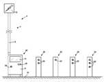
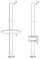
- FIG. 1illustrates an antenna mast 2 according to embodiments.
- the antenna mast 2comprises a mast body 4 comprising a lower module 6 and an upper module 8 .
- the lower module 6is attached to the ground 10 and supports the mast body 4 and the antenna mast 2 in its upright position.
- the lower module 6 and the upper module 8have been assembled to form the mast body 4 .
- the lower module 6 and the upper module 8have been selected from a set of modules comprising different lower modules and different upper modules.
- the antenna mast 2forms part of a wireless communication system.
- the upper modulesupports an antenna arrangement of the wireless communication system.
- the mast body 4may house a transceiver arrangement and a processor of the wireless communication system.
- the transceiver arrangementmay comprise a separate transmitter and a separate receiver, or a combined transceiver.
- the transceiver arrangement and the processormay be comprised in one unit.
- the antenna arrangement, the transceiver arrangement and the processorare involved in communication between random users of the wireless communication system, such as two persons communicating via mobile telephone or a wireless device which via a web browser accesses a website stored on a server.
- the lower module 6carries the weight of the upper module 8 , and the antenna arrangement as well as any transceiver arrangement and processor in the mast body 4 .
- the upper module 8comprises a device to be utilized for a further function, i.e. a function other than supporting the antenna arrangement.
- the device to be utilized for the further function of the upper moduleis a sign 12 .
- the sign 12indicates a vehicle parking facility.
- the antenna arrangement supported by the antenna mastis arranged inside the sign 12 .
- the lower module 6comprises devices to be utilized for further functions.
- a first devicecomprises an electronic screen 14 on which information may be presented.
- the screen 14may be a touch screen such that a user may provide input to the first device.
- a second devicecomprises a card-reading device 16 .
- the card-reading device 16may for instance read plastic cards provided with a magnetic strip and/or a readable chip, such as a credit card.
- a third device to be utilized for a further functionis a parking meter 18 comprising the electronic screen 14 and the card-reading device 16 .
- a vehicle owner who desires to park his vehicle in the parking facility indicated by the sign 12may thus receive information about the parking fee via the screen 14 and via the touch screen input the duration for parking the vehicle.
- the usermay insert a credit card in the card-reading device 16 to pay for parking the vehicle.
- a receiptmay be printed by a non-shown printer.
- the printermay form a fourth device to be utilized for a further function of the lower module 6 .
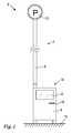
- FIG. 2illustrates an antenna mast 2 according to embodiments.
- the antenna mast 2comprises a mast body 4 comprising a lower module 6 and an upper module 8 .
- the lower module 6is attached to the ground 10 and supports the mast body 4 and the antenna mast 2 in its upright position.
- the mast body 4has been assembled from the lower module 6 and the upper module 8 , which have been selected from a set of modules comprising different lower modules and different upper modules.
- the antenna mast 2forms part of a wireless communication system and at an upper end of the antenna mast 2 , the upper module 8 supports an antenna arrangement of the wireless communication system.
- the mast body 4may house a transceiver arrangement and a processor of the wireless communication system.
- the upper module 8comprises a device to be utilized for a further function in the form of a sign 12 and the lower module 6 comprises several devices to be utilized for further functions.
- the antenna mast 2comprises an arrangement 20 for charging an electric vehicle.
- the sign 12indicates such an arrangement.
- the lower module 6thus comprises a device to be utilized for a further function in the form of an arrangement 20 for charging an electric vehicle.
- the arrangement 20comprises three devices to be utilized for a further function; a first device comprising an electronic screen 14 , a second device comprising a card-reading device 16 , and a third device comprising an electric power socket 22 .
- the electronic screen 14 and the card-reading device 16may function as mentioned above in connection with the parking meter.
- the electric power socket 22is provided for an owner of an electric vehicle to charge the electric vehicle.
- a number of separate charging posts 24may be connected to the arrangement 20 for charging an electronic vehicle.
- a user desiring to charge a vehiclemay thus be directed by instructions on the screen 14 to an available power socket 22 on one of the posts 24 for charging the vehicle.
- the lower modules 6 and the upper modules 8 illustrated in FIGS. 1 and 2form part of a set of modules. Accordingly, the set of modules comprises at least two different lower modules 6 and at least two different upper modules 8 .
- the set of modulesmay comprise further lower modules 6 and/or upper modules 8 of the same kind as illustrated in FIGS. 1 and 2 and/or of a different kind than illustrated in FIGS. 1 and 2 .
- An antenna mast systemmay comprise the set of modules.
- differently configured mast bodies 4may be assembled from the set of modules.
- a method of providing an antenna mast 2may thus comprise selecting a lower module 6 and an upper module 8 from a set of modules, and assembling a mast body 4 including the selected lower module 6 and the selected upper module 8 to form an assembled mast body 4 .
- FIG. 3illustrates an antenna mast 2 according to embodiments.
- the antenna mast 2comprises a mast body 4 comprising a lower module 6 , a middle module 30 , and an upper module 8 .
- the lower module 6is attached to the ground and supports the mast body 4 and the antenna mast 2 in its upright position.
- the mast body 4has been assembled from the lower module 6 , the middle module 30 , and the upper module 8 , which have been selected from a set of modules comprising different lower modules, different middle modules, and different upper modules.
- the antenna mast 2forms part of a wireless communication system and at an upper end of the antenna mast 2 , the upper module 8 supports an antenna arrangement of the wireless communication system.
- the mast body 4may house a transceiver arrangement and a processor of the wireless communication system.
- the antenna mast 2is adapted to be placed at an antenna site where members of the public may want to sit down or may want to know the time of day, such as at a public transportation station or at a shopping centre.
- the upper modulecomprises a device to be utilized for a further function other than supporting the antenna arrangement in the form of a clock 32 .
- the lower module 6thus comprises a device to be utilized for a further function in the form of a bench 34 .
- the middle module 30 in these embodimentsforms an extension for positioning the clock 32 and the antenna arrangement of the upper module 8 at a suitable height, such as at 3-8 meters above the ground.
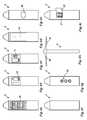
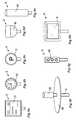
- FIGS. 4 a - 4 iillustrate embodiments of lower modules 6 of antenna masts.
- the lower modules 6 illustrated in FIGS. 4 a - 4 e , and 4 g - 4 ieach comprise at least one device to be utilized for a further function, i.e. a function other than supporting an antenna arrangement of a relevant antenna mast.
- FIG. 4 aillustrates a lower module 6 comprising a device to be utilized for a further function in the form of a vending machine 40 .
- FIG. 4 billustrates a lower module 6 comprising a device to be utilized for a further function in the form of a parking meter 18 .
- FIG. 4 cillustrates a lower module 6 comprising a device to be utilized for a further function in the form of an electronic screen 14 .
- FIG. 4 dillustrates a lower module 6 comprising a device to be utilized for a further function in the form of an electronic screen 14 .
- the electronic screens illustrated in FIGS. 4 c and 4 dare of different sizes. The larger screen 14 of FIG. 4 d may be suited for public announcements or commercial messages whereas the smaller screen of FIG. 4 c may be utilized for providing information to one person.
- FIG. 4 eillustrates a lower module 6 comprising a device to be utilized for a further function in the form of a waste bin 42 .
- FIG. 4 fillustrates a lower module 6 without any device to be utilized for a further function.
- FIG. 4 gillustrates a lower module 6 comprising a device to be utilized for a further function in the form of a traffic light 44 for a pedestrian or bicycle crossing.
- FIG. 4 hillustrates a lower module 6 comprising a first device to be utilized for a further function in the form of a lighting arrangement 45 , such as an electric lamp, and a second device to be utilized for a further function in the form of a roof arrangement 46 .
- FIG. 4 iillustrates a lower module 6 comprising a device to be utilized for a further function in the form of a defibrillator 47 .
- At least the electrodes of the defibrillator 47are arranged in a compartment inside the lower module 6 . By opening a door 48 of the compartment at least the electrodes of the defibrillator 47 may be taken out of the compartment for aiding a person in need.
- At least one of the devices to be utilized for a further function illustrated in each of the FIGS. 4 a - 4 e , and 4 g - 4 iis housed substantially within the lower modules 6 and thus within an outer surface of the lower module 6 . Portions of the devices which need to be accessible or visible in use are arranged at an outer surface of the lower module 6 .
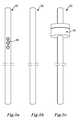
- FIGS. 5 a - 5 eillustrate embodiments of middle modules 30 of antenna masts.
- the middle modules 30 illustrated in FIGS. 5 a , and 5 c - 5 eeach comprise at least one device to be utilized for a further function, i.e. a function other than supporting an antenna arrangement of a relevant antenna mast.
- FIG. 5 aillustrates of a middle module 30 comprising a device to be utilized for a further function in the form of a traffic light 50 .
- FIG. 5 billustrates a middle module 30 without any device to be utilized for a further function. Inside this middle module 30 there may be arranged parts of the wireless communication system.
- FIGS. 5 a , 5 c , and 5 eillustrates embodiments of a middle module 30 comprising a device to be utilized for a further function in the form of a lighting arrangement 45 .
- FIG. 5 dillustrates embodiments of a middle module 30 comprising a device to be utilized for a further function in the form of a roof arrangement 46 .
- FIG. 5 eillustrates embodiments of a middle module 30 comprising a device to be utilized for a further function in the form of an electronic screen 14 .
- the devices to be utilized for a further function illustrated in FIGS. 5 a , 5 c , and 5 eare housed substantially within the middle modules 30 and thus within an outer surface of the middle modules 30 . Portions of the devices which need to be accessible or visible in use are arranged at an outer surface of the middle modules 30 .
- FIGS. 6 a - 6 hillustrate embodiments of upper modules 8 of antenna masts.
- the upper modules 8 illustrated in FIGS. 6 a - 6 hsupport an antenna arrangement of a wireless communication system.
- FIGS. 6 a - 6 d , and 6 f - 6 heach comprise at least one device to be utilized for a further function, i.e. a function other than supporting an antenna arrangement of a relevant antenna mast.
- FIG. 6 aillustrates an upper module 8 comprising a device to be utilized for a further function in the form of a sign 12 for a public buss service.
- FIG. 6 billustrates an upper module 8 comprising a device to be utilized for a further function in the form of a clock 32 .
- FIG. 6 cillustrates an upper module 8 comprising a device to be utilized for a further function in the form of a parking sign 12 .
- FIG. 6 dillustrates an upper module 8 comprising a device to be utilized for a further function in the form of a lighting arrangement 45 , such as an electric streetlamp.
- FIG. 6 eillustrates an upper module 8 without any device to be utilized for a further function.
- Inside a shell 62 permeable to radio wavesthe antenna arrangement of a wireless communication system is arranged.
- FIG. 6 fillustrates an upper module 8 comprising a device to be utilized for a further function in the form of a roof arrangement 46 .
- Inside a shell 62 permeable to radio wavesthe antenna arrangement of a wireless communication system is arranged.
- FIG. 6 gillustrates an upper module 8 comprising a device to be utilized for a further function in the form of a traffic light 50 .
- FIG. 6 hillustrates an upper module 8 comprising a device to be utilized for a further function in the form of an electronic screen 14 .
- the antenna arrangementis arranged inside each of the upper modules 8 illustrated in FIGS. 6 a - 6 h . At least a portion of an outer surface of the upper modules 8 is permeable to radio waves. Further parts of the wireless communication system may also be arranged in any of the upper modules 8 illustrated in FIGS. 6 a - 6 h .
- the devices to be utilized for a further function illustrated in FIGS. 6 b , 6 d , 6 g , and 6 hare housed substantially within the upper modules 8 and thus within an outer surface of the upper modules 8 . Portions of the devices which need to be accessible or visible in use are arranged at an outer surface of the upper modules 8 .
- the set of modulescomprises at least two different lower modules 6 , and/or at least two different middle modules 30 , and/or at least two different upper modules 8 .
- the set of modulesmay comprise all of, or a certain number of, the modules illustrated in FIGS. 4 a - 4 i , 5 a - 5 e , and 6 a - 6 h .
- An antenna mast systemmay comprise the set of modules.
- differently configured mast bodies 4may be assembled from the set of modules.
- a method of providing an antenna mast 2may thus comprise selecting a lower module 6 , a middle module 30 , and an upper module 8 from the set of modules, and assembling a mast body 4 including the selected lower module 6 , the selected middle module 30 , and the selected upper module 8 to form an assembled mast body.
- An assemble mast bodymay look like the mast body 4 illustrated in FIG. 3 when the set of modules also comprises a lower module 6 comprising a device to be utilized for a further function in the form of a bench 34 .
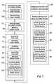
- FIG. 7is a flow chart illustrating embodiments of a method of providing an antenna mast for a wireless communication system.
- the antenna mast 2may be of the kind illustrated in FIGS. 1-3 and may comprise modules 6 , 8 , 30 as illustrated in FIGS. 4 a - 4 i , 5 a - 5 e , and 6 a - 6 h .
- the antenna mastcomprises a mast body adapted to form a supporting structure for an antenna arrangement of the wireless communication system.
- the mast bodycomprises a lower module and an upper module.
- the upper moduleis adapted to comprise the antenna arrangement. At least one of the lower module and the upper module is adapted to comprise a device to be utilized for a further function other than supporting the antenna arrangement.
- the methodcomprises:
- Assemblingmay comprise:
- the methodmay comprise:
- the methodmay comprise:
- the methodmay comprise:
- the methodmay comprise:
- the methodmay comprise:
- the methodmay comprise:
- the methodmay comprise:
- the methodmay comprise:
- the methodmay comprise:
- the methodmay comprise:
- the methodmay comprise:
- An antenna mastmay comprise more than three modules.
- One or more further modulesmay be placed on top of the upper module of a mast body of an antenna mast.
- the different modules of a mast bodymay be assembled in such a manner or using such method that they may be separated again, alternatively one or more of the different modules may be permanently attached to each other such that only mechanical damage will separate the modules.
- the modulesmay be provided with connecting elements, such as flanges or sleeves, to allow easy fitting and attachment of the lower module with a middle module or an upper module, and a middle module with an upper module.
- One or more antennasmay be arranged such that they are visible from an outside of the antenna mast.
- a further device to be utilized for a further functionmay comprise a monitoring arrangement for instance comprising a surveillance camera.
- An antenna mastmay have a height of 3-8 meters.
- Antenna mastsmay also have a higher height such as up to 15 meters.
- the common abbreviation “e.g.”, which derives from the Latin phrase “exempli gratia,”may be used to introduce or specify a general example or examples of a previously mentioned item, and is not intended to be limiting of such item. If used herein, the common abbreviation “i.e.”, which derives from the Latin phrase “id est,” may be used to specify a particular item from a more general recitation.
Landscapes
- Engineering & Computer Science (AREA)
- Power Engineering (AREA)
- Transportation (AREA)
- Mechanical Engineering (AREA)
- Computer Networks & Wireless Communication (AREA)
- Support Of Aerials (AREA)
Abstract
Description
The technical field concerned relates to a method of providing an antenna mast for a wireless communication system and a modular antenna mast system for providing antenna masts of a wireless communication system.
Wireless communication systems using radio communication comprise transceiver arrangements and processors comprised in what may be referred to as base stations, radio network controllers, or node B's. Furthermore, antennas are connected to the transceiver arrangements and are required for transmitting and receiving radio signals. The antennas may for instance be arranged on an antenna mast. A variety of masts have been suggested in the prior art but in practice a steel lattice mast is the most common type of mast used.
Wireless communication such as mobile internet access by means of mobile communication equipment is demanded by more people and more devices. Thus, radio traffic within the wireless communication systems increases and so does the required number of access points for the mobile communication equipment. For each access point at least one antenna is required and thus the number of antennas that are required increases with the increased demand in mobile internet access.
EP1198024 discloses an antenna mast wherein an antenna is raised and lowered along a guiding means inside the antenna mast. According to one embodiment, the antenna mast comprises a carrying pipe for a lamp.
U.S. Pat. No. 6,335,709 discloses a service tower integrating a water tank and an antenna mast in a single structure.
EP1286412 discloses a radio tower with a central supporting tower structure comprising several modules of the same outer shape being arranged one above the other. The modules house for instance transmission and power supply equipment. Further the tower comprises stiff ring-shaped portions of covering made from glass fibre reinforced plastic material, inside which the modules of the radio tower are arranged. Each ring-shaped covering is supported by a module of the radio tower. On the outside of the covering, screens for providing information or announcements may be arranged. Also the use of the covering for housing small shops or ticket machines is suggested.
WO98/58420 discloses a wireless communication pole system. The system is fully integrated for rapid installation. The system comprises a pole, a base assembly, and an antenna assembly. According to one embodiment the pole doubles as a banner-carrying light pole.
A high number of access points, and accordingly antennas, for wireless communication systems puts a requirement on associated antenna masts to be accepted by the public. Providing a further function other than supporting an antenna arrangement in connection with an antenna mast, as disclosed in the above-mentioned prior art documents, may facilitate such acceptance.
For instance in situations when a number of antenna masts are required in a restricted area, there exists a need to provide different further functions in the number of antenna masts to maintain the public acceptance. However, providing such a number of different further functions in connection with a number of antenna masts may prove to be a problem. The manufacturing and installation of such a number antenna masts may be complicated and costly.
An object is thus to at least alleviate the above mentioned problem.
According to one aspect, the object is achieved by a method of providing an antenna mast for a wireless communication system. The antenna mast comprising a mast body adapted to form a supporting structure for an antenna arrangement of the wireless communication system. The mast body comprises a lower module and an upper module. The upper module is adapted to comprise the antenna arrangement. At least one of the lower module and the upper module is adapted to comprise a device to be utilized for a further function other than supporting the antenna arrangement. The method comprises:
- selecting a lower module and an upper module from a set of modules comprising at least two different lower modules and/or at least two different upper modules, and
- assembling the mast body including the selected lower module and the selected upper module to form an assembled mast body.
Since the antenna mast provided according to the method, assembled including the selected lower module and upper module, may be designed for a specific further function, which may be different than a further function provided in a different antenna mast assembled from the same set of modules, high flexibility in the adaptation of antenna masts is provided. As a result, the above mentioned object is achieved.
The use of a set of modules comprising different lower modules and/or different upper modules may be a rational and advantageous way of manufacturing different antenna masts adapted to specific requirements at different antenna mast sites. For example, if the antenna mast site is an intersection between two streets, the device to be utilized for the further function may be a traffic light or a street sign. Accordingly, a lower module forming a base of the mast body may be selected from the set of modules and an upper module adapted to receive the lights of a traffic light, or adapted to form the street sign, may be selected from the set of modules. At a different example antenna mast site there may be a bus stop, in which case a lower module comprising a bench may be selected from the set of modules and an upper module adapted to support the antenna arrangement may be selected from the set of modules. A further example antenna mast site may be situated in a park area, in which case a lower module selected from the set of modules may comprise a waste bin and the upper module selected from the set of modules may be adapted to comprise a street light. Since different mast bodies may be provided, the antenna masts at different sites assembled from the set of modules may blend in well in a present environment. Public acceptance of antenna masts will thus be achieved in a rational manner.
The upper module being adapted to comprise the antenna arrangement encompasses that the antenna arrangement may be mounted to the upper module or arranged inside the upper module. The antenna arrangement is arranged at an elevated position on the antenna mast. Accordingly, the antenna arrangement may be provided at a top of the upper module, or it is alternatively foreseen that some portions of the upper module may be provided above the antenna arrangement. It is to be understood that the set of modules comprises at least one lower and one upper module, and at least one further of the lower and upper modules.
Different technologies may be used in wireless communication systems, such as Long Term Evolution (LTE), LTE-Advanced, 3rd Generation Partnership Project (3GPP) Wideband Code Division Multiple Access (WCDMA), Global System for Mobile Communications/Enhanced Data rate for GSM Evolution (GSM/EDGE), Worldwide Interoperability for Microwave Access (WiMax), or Ultra Mobile Broadband (UMB), just to mention a few possible implementations. A wireless communication system may comprise transceiver arrangements and processors providing radio coverage over at least one respective geographical area forming a cell. User equipment, such as mobile telephones, are served in the cells by the respective transceiver arrangements and processors and communicate with the respective transceiver arrangements and processors. An antenna mast may be erected at an antenna site in a cell. Typically, such antenna sites are outdoors in areas frequented by the public. In such areas, use of wireless communication systems is to be expected.
According to embodiments the further function may be a function other than a function directly related to the wireless communication system. It is to be understood that the device to be utilized for the further function of a specific assembled antenna mast may make use of the wireless communication system but the device is not involved in communication between random users of the wireless communication system utilizing the antenna arrangement of the specific assembled antenna mast. Put differently, the communication between the random users of the wireless communication system is performed independently of any communication relating to the device to be utilized for the further function. A device to be utilized for a further function may communicate e.g. its status of operation to a service provider via the wireless communication system.
According to embodiments assembling may comprise:
- arranging the lower module substantially below the upper module in the assembled mast body.
According to embodiments the method may comprise:
- manufacturing the lower modules, and the upper modules of the set of modules to form at least part of an outer surface of the assembled mast body. In this manner a mast body assembled from the set of modules may comprise a continuous outer surface.
According to embodiments the method may comprise:
- manufacturing lower modules to form a supporting structure which is adapted to carry at least a weight of an upper module and devices arranged in the upper module of an assembled mast body. In this manner a lower module may carry the weight of an assembled mast body and be fastened to the ground to support the relevant antenna mast.
According to embodiments the method may comprise:
- arranging the device to be utilized for the further function substantially within the outer surface of the assembled mast body. In this manner the device to be utilized for the further function may blend in well with the mast body to form a homogeneous antenna mast. The device to be utilized for the further function may be protectedly arranged in the antenna mast body.
According to embodiments the method may comprise:
- providing an antenna mast having a height of 3-8 meters.
According to embodiments the method may comprise:
- arranging a particular device to be utilized for the further function in the assembled mast body in dependence of the selected modules from the set of modules. The arranging of a particular device to be utilized for the further function in the mast body may thus depend on which specific module is selected from the set of modules. The device may be arranged in a module before the mast body is assembled or after the mast body has been assembled.
According to embodiments the method may comprise:
- arranging at least a transmitter, and/or a receiver, and a processor of the wireless communication system inside the selected lower and/or upper modules. In this manner the antenna mast may house these components of the wireless communication system. The arranging of the transmitter, and/or the receiver, and the processor inside the lower and/or upper modules may be done before the mast body is assembled or after the mast body has been assembled.
According to embodiments the method may comprise:
- providing the device to be utilized for the further function in connection with the lower module of the assembled mast body.
According to embodiments the method may comprise:
- selecting the device to be utilized for the further function from the group of: a bench, a roof arrangement, a waste bin, a vending machine, an electronic screen, a parking meter, a traffic light, a lighting arrangement, a card-reading device, an electric power socket, or a life-saving device such as a defibrillator. Different functions, services, and devices may thus be provided. A bench may be provided at antenna mast sites where members of the public may want to sit down. A roof arrangement may be provided at antenna mast sites where members of the public may need shelter from precipitation or the sun. A waste bin may be provided at an antenna mast site which is frequented by many people. A vending machine may be provided at an antenna mast site which is frequented by many people. An electronic screen may be provided at an antenna mast site where there is a need or requirement to provide information to one or more persons. A parking meter may be provided at an antenna mast site in vicinity of a vehicle parking facility. One or more traffic lights may be provided at an antenna mast site at a roadside, in a street intersection, or at a crossing for pedestrians. A card-reading device may be provided e.g. at an antenna mast sites where a service provider may want to charge for services provided, e.g. at a vehicle parking facility, an electric vehicle charging arrangement, a public transportation station, etc. An electric power socket may be provided at an antenna mast site where electric vehicles may be charged. A life-saving device, such as a defibrillator, or an oxygen container and mask, may be provided at an antenna mast site which is frequented by many people or a site where there may be a particular reason to provide such equipment.
According to embodiments the method may comprise:
- providing the device to be utilized for performing the further function besides the antenna arrangement in connection with the upper module of the assembled mast body.
According to embodiments the method may comprise: selecting the device to be utilized for the further function from a group of: a sign, a lighting arrangement, a clock, a roof arrangement, a traffic light, or an electronic screen. Different functions, services, and devices may thus be provided. A sign may be provided at an antenna mast site where information is to be displayed to members of the public. A lighting arrangement such as one or more lamps may be provided at an antenna mast site frequented by members of the public at dark hours. A clock may be provided at an antenna mast site near a public transportation station. A roof arrangement may be provided at an antenna mast site where members of the public may need shelter from precipitation or the sun. One or more traffic lights may be provided at an antenna mast site at a roadside, in a street intersection, or at a crossing for pedestrians. An electronic screen may be provided at an antenna mast site where there is a need or requirement to provide information to one or more persons.
According to embodiments the set of modules may comprise at least two different lower modules and/or at least two different middle modules and/or at least two different upper modules, and wherein selecting may comprise:
- selecting a middle module from the set of modules, and assembling may comprise:
- assembling the mast body including the selected middle module to form the assembled mast body. In this manner antenna masts comprising a middle module besides upper and lower modules may be provided. The middle modules being comprised in the set of modules ensures flexibility to provide an antenna mast adapted for a specific antenna mast site. More and/or different combinations of modules are provided.
According to embodiments, assembling the antenna mast body may comprise:
- arranging the middle module substantially between the lower module and the upper module.
According to embodiments the method may comprise:
- providing the device to be utilized for the further function in connection with the middle module.
According to embodiments the method may comprise: selecting the device to be utilized for the further function from a group of: a traffic light, an electronic screen, a roof arrangement, or a lighting arrangement. Different functions, services, and devices may thus be provided. One or more traffic lights may be provided at an antenna mast site at a roadside, in a street intersection, or at a crossing for pedestrians. An electronic screen may be provided at an antenna mast site where there is a need or requirement to provide information to one or more persons. A roof arrangement may be provided at an antenna mast site where members of the public may need shelter from precipitation or the sun. A lighting arrangement such as one or more lamps may be provided at an antenna mast site frequented by members of the public at dark hours.
According to embodiments a lower module of the set of modules may form a supporting structure which is adapted to carry a weight of a middle module, an upper module, and devices arranged in the middle and upper modules. In this manner a lower module may carry the weight of an assembled mast body and be fastened to the ground to support the relevant antenna mast.
According to a further aspect, the object is achieved by a modular antenna mast system for providing antenna masts of a wireless communication system, at least some of the antenna masts of the antenna mast system each comprising a mast body adapted to form a supporting structure for an antenna arrangement of the wireless communication system. The mast body comprises a lower module and an upper module, the upper module being adapted to comprise the antenna arrangement. At least one of the lower module and the upper module is adapted to comprise a device to be utilized for a further function other than supporting the antenna arrangement. The antenna mast system comprises a set of modules comprising lower and upper modules, wherein the set of modules comprises at least two different lower modules and/or at least two different upper modules such that differently configured mast bodies comprising a lower and an upper module are able to be assembled from the set of modules.
Since the antenna mast system comprises a set of modules from which differently configured mast bodies are assembled, an antenna mast may be designed for a specific further function, which may be different than a further function provided in a different antenna mast assembled from the same set of modules. Again, high flexibility in the adaptation of antenna masts to a particular antenna site is provided. As a result, the above mentioned object is achieved.
According to embodiments the further function may be a function other than a function directly related to the wireless communication system. It is to be understood that the device to be for the further function of a specific assembled antenna mast may make use of the wireless communication system but the device is not involved in communication between random users of the wireless communication system utilizing the antenna arrangement of the specific assembled antenna mast. For instance, a device to be utilized for a further function may communicate its status of operation to a service provider via the wireless communication system.
According to embodiments a lower module may be arranged substantially below an upper module in an assembled mast body of an antenna mast of the antenna mast system.
According to embodiments a lower module and an upper module may form at least part of an outer surface of an assembled mast body of an antenna mast of the antenna mast system. In this manner a mast body assembled from the set of modules may comprise a continuous outer surface.
According to embodiments a lower module of the set of modules may form a supporting structure which is adapted to carry at least a weight of an upper module and devices arranged in the upper module of an assembled mast body. In this manner a lower module may carry the weight of an assembled mast body and be fastened to the ground to support the relevant antenna mast.
According to embodiments an assembled mast body of an antenna mast of the antenna mast system may be adapted to house the device to be utilized for the further function substantially within the outer surface of the assembled mast body. In this manner the device to be utilized for the further function may blend in well with the mast body to form a homogeneous antenna mast. The device to be utilized for the further function may be protectedly arranged in the antenna mast body.
According to embodiments at least some of the antennas masts of the antenna mast system may have a height of 3-8 meters.
According to embodiments the differently configured mast bodies of the modular antenna mast system may be arranged to comprise different devices to be utilized for the further function depending on which modules are selected from the set of modules for a particular mast body. The arranging of a particular device to be utilized for the further function in the mast body may thus depend on which specific module is selected from the set of modules. The device may be arranged in a module before the mast body is assembled or after the mast body has been assembled.
According to embodiments at least one of the differently configured mast bodies may be adapted to house therein at least a transmitter and/or a receiver and a processor of the wireless communication system. In this manner an antenna mast with a mast body may be provided, which may be adapted to provide for the device for performing the further function, and which also may house key components of the wireless communication system.
According to embodiments at least one lower module of the set of modules may be adapted to comprise the device to be utilized for the further function.
According to embodiments the device to be utilized for the further function may comprise a bench, a roof arrangement, a waste bin, a vending machine, an electronic screen, a parking meter, a traffic light, a lighting arrangement, a card-reading device, an electric power socket, or a life-saving device such as a defibrillator.
According to embodiments at least one upper module of the set of modules may be adapted to comprise the device to be utilized for the further function, besides the antenna arrangement.
According to embodiments the device to be utilized for the further function may comprises: a sign, a lighting arrangement, a clock, a roof arrangement, a traffic light, or an electronic screen.
According to embodiments the set of modules may comprise at least two different lower modules and/or at least two different middle modules and/or at least two different upper modules such that differently configured mast bodies comprising a middle module are able to be assembled from the set of modules. In this manner antenna masts comprising a middle module besides upper and lower modules may be provided. The middle modules being comprised in the set of modules ensures flexibility to provide an antenna mast adapted for a specific antenna mast site.
According to embodiments a middle module may be arranged substantially between a lower module and an upper module of an assembled mast body of an antenna mast of the antenna mast system.
According to embodiments at least one middle module of the set of modules may be adapted to comprise the device to be utilized for the further function.
According to embodiments the device to be utilized for the further function may comprise: a traffic light, an electronic screen, a roof arrangement, or a lighting arrangement.
According to embodiments a lower module forms a supporting structure which is adapted to carry a weight of a middle module, an upper module, and devices arranged in the middle and upper modules. In this manner a lower module may carry the weight of an assembled mast body and be fastened to the ground to support the relevant antenna mast.
Further features of, and advantages, will become apparent when studying the appended claims and the following detailed description. Those skilled in the art will realize that different features of embodiments may be combined to create embodiments other than those described in the following, without departing from the scope defined by the appended claims.
The various aspects of embodiments, including particular features and advantages, will be readily understood from the following detailed description and the accompanying drawings, in which:
Embodiments will now be described more fully with reference to the accompanying drawings, in which example embodiments are shown. The embodiments set forth herein should not be construed as limiting. Disclosed features of example embodiments may be combined as readily understood by one of ordinary skill in the art. Like numbers refer to like elements throughout.
Well-known functions or constructions will not necessarily be described in detail for brevity and/or clarity.
Theantenna mast 2 forms part of a wireless communication system. At an upper end of theantenna mast 2 the upper module supports an antenna arrangement of the wireless communication system. Themast body 4 may house a transceiver arrangement and a processor of the wireless communication system. The transceiver arrangement may comprise a separate transmitter and a separate receiver, or a combined transceiver. Also the transceiver arrangement and the processor may be comprised in one unit. The antenna arrangement, the transceiver arrangement and the processor are involved in communication between random users of the wireless communication system, such as two persons communicating via mobile telephone or a wireless device which via a web browser accesses a website stored on a server.
Thelower module 6 carries the weight of theupper module 8, and the antenna arrangement as well as any transceiver arrangement and processor in themast body 4.
Theupper module 8 comprises a device to be utilized for a further function, i.e. a function other than supporting the antenna arrangement. In these embodiments the device to be utilized for the further function of the upper module is asign 12. In these embodiments thesign 12 indicates a vehicle parking facility. The antenna arrangement supported by the antenna mast is arranged inside thesign 12.
Thelower module 6 comprises devices to be utilized for further functions. A first device comprises anelectronic screen 14 on which information may be presented. Thescreen 14 may be a touch screen such that a user may provide input to the first device. A second device comprises a card-readingdevice 16. The card-readingdevice 16 may for instance read plastic cards provided with a magnetic strip and/or a readable chip, such as a credit card. A third device to be utilized for a further function is aparking meter 18 comprising theelectronic screen 14 and the card-readingdevice 16. A vehicle owner who desires to park his vehicle in the parking facility indicated by thesign 12 may thus receive information about the parking fee via thescreen 14 and via the touch screen input the duration for parking the vehicle. The user may insert a credit card in the card-readingdevice 16 to pay for parking the vehicle. A receipt may be printed by a non-shown printer. The printer may form a fourth device to be utilized for a further function of thelower module 6.
Again, theantenna mast 2 forms part of a wireless communication system and at an upper end of theantenna mast 2, theupper module 8 supports an antenna arrangement of the wireless communication system. Themast body 4 may house a transceiver arrangement and a processor of the wireless communication system.
Theupper module 8 comprises a device to be utilized for a further function in the form of asign 12 and thelower module 6 comprises several devices to be utilized for further functions.
In these embodiments theantenna mast 2 comprises anarrangement 20 for charging an electric vehicle. Accordingly, thesign 12 indicates such an arrangement. Thelower module 6 thus comprises a device to be utilized for a further function in the form of anarrangement 20 for charging an electric vehicle. Thearrangement 20 comprises three devices to be utilized for a further function; a first device comprising anelectronic screen 14, a second device comprising a card-readingdevice 16, and a third device comprising anelectric power socket 22. Theelectronic screen 14 and the card-readingdevice 16 may function as mentioned above in connection with the parking meter. Theelectric power socket 22 is provided for an owner of an electric vehicle to charge the electric vehicle. A number of separate charging posts24, each comprising one or moreelectric power sockets 22, may be connected to thearrangement 20 for charging an electronic vehicle. A user desiring to charge a vehicle may thus be directed by instructions on thescreen 14 to anavailable power socket 22 on one of theposts 24 for charging the vehicle.
Thelower modules 6 and theupper modules 8 illustrated inFIGS. 1 and 2 form part of a set of modules. Accordingly, the set of modules comprises at least two differentlower modules 6 and at least two differentupper modules 8. The set of modules may comprise furtherlower modules 6 and/orupper modules 8 of the same kind as illustrated inFIGS. 1 and 2 and/or of a different kind than illustrated inFIGS. 1 and 2 . An antenna mast system may comprise the set of modules. Thus, differently configuredmast bodies 4 may be assembled from the set of modules. A method of providing anantenna mast 2 may thus comprise selecting alower module 6 and anupper module 8 from a set of modules, and assembling amast body 4 including the selectedlower module 6 and the selectedupper module 8 to form an assembledmast body 4.
Again, theantenna mast 2 forms part of a wireless communication system and at an upper end of theantenna mast 2, theupper module 8 supports an antenna arrangement of the wireless communication system. Themast body 4 may house a transceiver arrangement and a processor of the wireless communication system. In these embodiments theantenna mast 2 is adapted to be placed at an antenna site where members of the public may want to sit down or may want to know the time of day, such as at a public transportation station or at a shopping centre. The upper module comprises a device to be utilized for a further function other than supporting the antenna arrangement in the form of aclock 32. Thelower module 6 thus comprises a device to be utilized for a further function in the form of abench 34. Themiddle module 30 in these embodiments forms an extension for positioning theclock 32 and the antenna arrangement of theupper module 8 at a suitable height, such as at 3-8 meters above the ground.
The antenna arrangement is arranged inside each of theupper modules 8 illustrated inFIGS. 6 a-6h. At least a portion of an outer surface of theupper modules 8 is permeable to radio waves. Further parts of the wireless communication system may also be arranged in any of theupper modules 8 illustrated inFIGS. 6 a-6h. The devices to be utilized for a further function illustrated inFIGS. 6 b,6d,6g, and6hare housed substantially within theupper modules 8 and thus within an outer surface of theupper modules 8. Portions of the devices which need to be accessible or visible in use are arranged at an outer surface of theupper modules 8.
At least one of thelower modules 6 ofFIGS. 4 a-4i, at least one of themiddle modules 30 ofFIGS. 5 a-5e, and at least one of theupper modules 8 ofFIGS. 6 a-6htogether with at least one further of thelower modules 6 ofFIGS. 4 a-4i, or themiddle modules 30 ofFIGS. 5 a-5e, or theupper modules 8 ofFIGS. 6 a-6hform a set of modules. Accordingly, the set of modules comprises at least two differentlower modules 6, and/or at least two differentmiddle modules 30, and/or at least two differentupper modules 8. The set of modules may comprise all of, or a certain number of, the modules illustrated inFIGS. 4 a-4i,5a-5e, and6a-6h. An antenna mast system may comprise the set of modules. Thus, differently configuredmast bodies 4 may be assembled from the set of modules. A method of providing anantenna mast 2 may thus comprise selecting alower module 6, amiddle module 30, and anupper module 8 from the set of modules, and assembling amast body 4 including the selectedlower module 6, the selectedmiddle module 30, and the selectedupper module 8 to form an assembled mast body. An assemble mast body may look like themast body 4 illustrated inFIG. 3 when the set of modules also comprises alower module 6 comprising a device to be utilized for a further function in the form of abench 34.
- Selecting70 a lower module and an upper module from a set of modules comprising at least two different lower modules and/or at least two different upper modules.
- Assembling72 the mast body including the selected lower module and the selected upper module to form an assembled mast body. The further function may be a function other than a function directly related to the wireless communication system.
Assembling may comprise:
- Arranging74 the lower module substantially below the upper module in the assembled mast body.
The method may comprise:
Manufacturing 76 the lower modules, and the upper modules of the set of modules to form at least part of an outer surface of the assembled mast body.
The method may comprise:
Manufacturing 78 lower modules to form a supporting structure which is adapted to carry at least a weight of an upper module and devices arranged in the upper module of an assembled mast body.
The method may comprise:
- Arranging80 the device to be utilized for the further function substantially within the outer surface of the assembled mast body.
The method may comprise:
- Providing82 an antenna mast having a height of 3-8 meters.
The method may comprise:
- Arranging84 a particular device to be utilized for the further function in the assembled mast body in dependence of the selected modules from the set of modules.
The method may comprise:
- Arranging86 at least a transmitter, and/or a receiver, and a processor of the wireless communication system inside the selected lower and/or upper modules.
The method may comprise:
- Providing88 the device to be utilized for the further function in connection with the lower module of the assembled mast body.
The method may comprise:
- Selecting90 the device to be utilized for the further function from the group of: a bench, a roof arrangement, a waste bin, a vending machine, an electronic screen, a parking meter, a traffic light, a lighting arrangement, a card-reading device, an electric power socket, or a life-saving device such as a defibrillator.
The method may comprise:
- Providing92 the device to be utilized for performing the further function besides the antenna arrangement in connection with the upper module of the assembled mast body.
The method may comprise:
- Selecting94 the device to be utilized for the further function from a group of: a sign, a lighting arrangement, a clock, a roof arrangement, a traffic light, or an electronic screen.
If the set of modules comprises at least two different middle modules the method may comprise:
- Selecting96 a middle module from the set of modules, and assembling72 comprises:
- Assembling98 the mast body including the selected middle module to form the assembled mast body. Assembling98 the antenna mast body may comprise:
- Arranging100 the middle module substantially between the lower module and the upper module. The method may comprise:
- Providing102 the device to be utilized for the further function in connection with the middle module. The method may comprise:
- Selecting104 the device to be utilized for the further function in the middle module from a group of: a traffic light, an electronic screen, a roof arrangement, or a lighting arrangement. The method may comprise:
- Manufacturing106 the lower modules of the set of modules to form a supporting structure which is adapted to carry a weight of a middle module, an upper module, and devices arranged in the middle and upper modules.
Example embodiments described above may be combined as understood by a person skilled in the art. It is also understood by those skilled in the art that steps of the method illustrated inFIG. 7 may be performed in a different order than illustrated inFIG. 7 . An antenna mast may comprise more than three modules. One or more further modules may be placed on top of the upper module of a mast body of an antenna mast. The different modules of a mast body may be assembled in such a manner or using such method that they may be separated again, alternatively one or more of the different modules may be permanently attached to each other such that only mechanical damage will separate the modules. The modules may be provided with connecting elements, such as flanges or sleeves, to allow easy fitting and attachment of the lower module with a middle module or an upper module, and a middle module with an upper module. One or more antennas may be arranged such that they are visible from an outside of the antenna mast. A further device to be utilized for a further function may comprise a monitoring arrangement for instance comprising a surveillance camera. An antenna mast may have a height of 3-8 meters. Antenna masts may also have a higher height such as up to 15 meters.
Therefore, it is to be understood that the foregoing is illustrative of various example embodiments and that modifications to the disclosed embodiments, combinations of features of disclosed embodiments as well as other embodiments are intended to be included within the scope of the appended claims.
As used herein, the term “comprising” or “comprises” is open-ended, and includes one or more stated features, elements, steps, components or functions but does not preclude the presence or addition of one or more other features, elements, steps, components, functions or groups thereof.
As used herein, the term “and/or” includes any and all combinations of one or more of the associated listed items.
As used herein, the common abbreviation “e.g.”, which derives from the Latin phrase “exempli gratia,” may be used to introduce or specify a general example or examples of a previously mentioned item, and is not intended to be limiting of such item. If used herein, the common abbreviation “i.e.”, which derives from the Latin phrase “id est,” may be used to specify a particular item from a more general recitation.
The terminology used herein is for the purpose of describing particular embodiments only and is not intended to be limiting. As used herein, the singular forms “a”, “an” and “the” are intended to include the plural forms as well, unless the context clearly indicates otherwise.
Unless otherwise defined, all terms (including technical and scientific terms) used herein have the same meaning as commonly understood by one of ordinary skill in the art belongs. It will be further understood that terms, such as those defined in commonly used dictionaries, should be interpreted as having a meaning that is consistent with their meaning in the context of the relevant art and will not be interpreted in an idealized or overly formal sense unless expressly so defined herein.
It will be understood that when an element is referred to as being “coupled” or “connected” to another element, it can be directly coupled or connected to the other element or intervening elements may also be present. In contrast, when an element is referred to as being “directly coupled” or “directly connected” to another element, there are no intervening elements present.
Claims (31)
1. A method of providing an antenna mast for a wireless communication system, the method comprising:
selecting a lower module and an upper module from a set of modules, wherein the set of modules comprises either:
one or more upper modules and two or more different kinds of lower modules, wherein the two or more different kinds of lower modules have the same connecting element for interchangeably connecting to a connecting element of an upper module;
one or more lower modules and two or more different kinds of upper modules, wherein the two or more different kinds of upper modules have the same connecting element for interchangeably connecting to a connecting element of a lower module; or
two or more different kinds of lower modules and two or more different kinds of upper modules;
wherein lower or upper modules of different kinds are configured to include therein different kinds of electronic devices that perform different functions; and
assembling the selected lower module and the selected upper module into a mast body of the antenna mast that forms a supporting structure for an antenna arrangement of the wireless communication system, including the antenna arrangement in the selected upper module and including an electronic device in at least one of the selected lower module and the selected upper module, wherein the electronic device included in a selected module is a kind of electronic device for which that selected module is configured;
wherein said assembling comprises:
selecting from a first plurality of different electronic devices a first electronic device in the form of an electronic screen configured to display public announcements or commercial messages;
including the electronic screen substantially within the outer surface of the selected lower module, such that at least a portion of the electronic screen is arranged at the selected lower module's outer surface so as to be visible;
selecting from a second plurality of different electronic devices a second electronic device in the form of a clock;
including the clock substantially within the outer surface of the selected upper module, such that at least a portion of the clock is arranged at the selected upper module's outer surface so as to be visible;
arranging the lower module substantially below the upper module in the assembled mast body;
including a processor and at least one of a transmitter and a receiver of the wireless communication system inside at least one of the selected lower and upper modules; and
wherein at least a portion of the upper module's outer surface is permeable to radio waves.
2. The method according toclaim 1 , wherein two or more of the different kinds of electronic devices perform different functions not directly related to the wireless communication system.
3. The method according toclaim 1 , further comprising manufacturing the lower modules and the upper modules of the set to form at least part of an outer surface of an assembled mast body.
4. The method according toclaim 1 , further comprising manufacturing lower modules to form a supporting structure that supports at least the weight of an upper module and devices included in that upper module.
5. The method according toclaim 1 , wherein said assembling comprises assembling the mast body to have a height between 3 and 8 meters.
6. The method according toclaim 1 , wherein said assembling comprises including different electronic devices in the assembled mast body based on the particular modules selected from the set of modules.
7. The method according toclaim 1 , wherein said first plurality of different electronic devices include two or more of a waste bin, a vending machine, an electronic screen, a parking meter, a traffic light, a lighting arrangement, a card-reading device, an electric power socket, and a life-saving device.
8. The method according toclaim 1 , wherein said second plurality of different devices include two or more of a sign, a lighting arrangement, a clock, a traffic light, and an electronic screen.
9. The method according toclaim 1 , wherein the set of modules further comprises at least two different middle modules that have the same connecting element for interchangeably connecting to a connecting element of a lower module and the same connecting element for interchangeably connecting to a connecting element of an upper module, wherein said selecting further comprises selecting a middle module from the set of modules, and wherein said assembling comprises assembling the selected middle module together with the selected lower and upper modules to form the assembled mast body.
10. The method according toclaim 9 , wherein said assembling comprises arranging the selected middle module substantially between the selected lower module and the selected upper module.
11. The method according toclaim 9 , wherein said assembling comprises including an electronic device in the selected middle module, wherein that electronic device is a kind of electronic device for which the selected middle module is configured.
12. The method according toclaim 11 , further comprising selecting the electronic device to include in the middle module from a plurality of different electronic devices, wherein said plurality of different electronic devices include a traffic light, an electronic screen, and a lighting arrangement.
13. The method according toclaim 9 , wherein a lower module is configured to form a supporting structure that supports the weight of a middle module, an upper module, and devices included in the middle and upper modules.
14. The method according toclaim 1 , wherein the set of modules comprises two or more different kinds of lower modules and two or more different kinds of upper modules, wherein the two or more different kinds of upper modules have the same connecting element for interchangeably connecting to the two or more different kinds of lower modules.
15. The method according toclaim 1 , wherein at least one of the electronic screen and the clock is configured to communicate with a service provider via the wireless communication system.
16. The method according toclaim 15 , wherein at least one of the electronic screen and the clock is configured to communicate its status of operation to said service provider via the wireless communication system.
17. A modular antenna mast system comprising a set of modules, including lower modules and upper modules, wherein at least two of the lower modules, at least two of the upper modules, or both are different from one another in kind, wherein lower or upper modules of different kinds are configured to include therein different kinds of electronic devices that perform different functions, wherein said at least two of the lower modules have the same connecting element for interchangeably connecting to a connecting element of at least one of the upper modules, wherein said at least two of the upper modules have the same connecting element for interchangeably connecting to a connecting element of at least one of the lower modules, wherein different pairs of lower and upper modules are configured to assemble together into differently configured mast bodies of antenna masts for a wireless communication system, wherein each mast body forms a supporting structure for an antenna arrangement of the wireless communication system, has an upper module configured to include the antenna arrangement, and has either an upper module, a lower module, or both configured to include therein one of said different kinds of electronic devices for which that module is configured, wherein a lower module is configured to assemble into a mast body at a position substantially below that of a paired upper module, wherein at least a portion of the upper module's outer surface is permeable to radio waves, wherein at least one of the differently configured mast bodies is configured to house therein a processor and at least one of a transmitter and a receiver of the wireless communication system, wherein at least one lower module in the set of modules is configured to include an electronic screen substantially within the outer surface of that lower module, such that at least a portion of the electronic screen is arranged at the lower module's outer surface so as to be visible, and wherein at least one upper module in the set of modules is configured to include a clock substantially within the outer surface of that upper module, such that at least a portion of the clock is arranged at the upper module's outer surface so as to be visible.
18. The modular antenna mast system according toclaim 17 , wherein two or more of the different kinds of electronic devices perform different functions not directly related to the wireless communication system.
19. The modular antenna mast system according toclaim 17 , wherein a lower module and an upper module are configured to form at least part of an outer surface of an assembled mast body.
20. The modular antenna mast system according toclaim 17 , wherein a lower module is configured to form a supporting structure that supports at least the weight of an upper module and devices included in that upper module.
21. The modular antenna mast system according toclaim 17 , wherein at least some of said antenna masts are configured to have a height between 3 and 8 meters.
22. The modular antenna mast system according toclaim 17 , wherein the differently configured mast bodies include different kinds of electronic devices that perform different functions.
23. The modular antenna mast system according toclaim 17 , wherein lower modules of different kinds are configured to include therein different kinds of electronic devices that include two or more of a waste bin, a vending machine, an electronic screen, a parking meter, a traffic light, a lighting arrangement, a card-reading device, an electric power socket, and a life-saving device.
24. The modular antenna mast system according toclaim 17 , wherein upper modules of different kinds are configured to include therein different kinds of electronic devices that include two or more of a sign, a lighting arrangement, a clock, a traffic light, and an electronic screen.
25. The modular antenna mast system according toclaim 17 , wherein the set of modules further comprises at least two different middle modules that have the same connecting element for interchangeably connecting to a connecting element of a lower module and the same connecting element for interchangeably connecting to a connecting element of an upper module, and wherein at least one of the differently configured mast bodies comprises a middle module assembled together with a pair of lower and upper modules.
26. The modular antenna mast system according toclaim 25 , wherein a middle module is positioned substantially between a lower module and an upper module of an assembled mast body.
27. The modular antenna mast system according toclaim 25 , wherein at least one middle module in the set of modules is configured to include one of said different kinds of electronic devices.
28. The modular antenna mast system according toclaim 25 , wherein different middle modules are configured to include therein different kinds of electronic devices that include two or more of a traffic light, an electronic screen, and a lighting arrangement.
29. The modular antenna mast system according toclaim 17 , wherein the set of modules comprises two or more different kinds of lower modules and two or more different kinds of upper modules, wherein the two or more different kinds of upper modules have the same connecting element for interchangeably connecting to the two or more different kinds of lower modules.
30. The modular antenna mast according toclaim 17 , wherein at least one of the electronic screen and the clock is configured to communicate with a service provider via the wireless communication system.
31. The modular antenna mast according toclaim 30 , wherein at least one of the electronic screen and the clock is configured to communicate its status of operation to said service provider via the wireless communication system.
Priority Applications (1)
| Application Number | Priority Date | Filing Date | Title |
|---|---|---|---|
| US13/025,531US8970438B2 (en) | 2011-02-11 | 2011-02-11 | Method of providing an antenna mast and an antenna mast system |
Applications Claiming Priority (1)
| Application Number | Priority Date | Filing Date | Title |
|---|---|---|---|
| US13/025,531US8970438B2 (en) | 2011-02-11 | 2011-02-11 | Method of providing an antenna mast and an antenna mast system |
Publications (2)
| Publication Number | Publication Date |
|---|---|
| US20120206306A1 US20120206306A1 (en) | 2012-08-16 |
| US8970438B2true US8970438B2 (en) | 2015-03-03 |
Family
ID=46636478
Family Applications (1)
| Application Number | Title | Priority Date | Filing Date |
|---|---|---|---|
| US13/025,531Active2031-06-19US8970438B2 (en) | 2011-02-11 | 2011-02-11 | Method of providing an antenna mast and an antenna mast system |
Country Status (1)
| Country | Link |
|---|---|
| US (1) | US8970438B2 (en) |
Cited By (162)
| Publication number | Priority date | Publication date | Assignee | Title |
|---|---|---|---|---|
| US9312919B1 (en) | 2014-10-21 | 2016-04-12 | At&T Intellectual Property I, Lp | Transmission device with impairment compensation and methods for use therewith |
| US9461706B1 (en) | 2015-07-31 | 2016-10-04 | At&T Intellectual Property I, Lp | Method and apparatus for exchanging communication signals |
| US9467870B2 (en) | 2013-11-06 | 2016-10-11 | At&T Intellectual Property I, L.P. | Surface-wave communications and methods thereof |
| US9479266B2 (en) | 2013-12-10 | 2016-10-25 | At&T Intellectual Property I, L.P. | Quasi-optical coupler |
| US9490869B1 (en) | 2015-05-14 | 2016-11-08 | At&T Intellectual Property I, L.P. | Transmission medium having multiple cores and methods for use therewith |
| US9503189B2 (en) | 2014-10-10 | 2016-11-22 | At&T Intellectual Property I, L.P. | Method and apparatus for arranging communication sessions in a communication system |
| US9509415B1 (en) | 2015-06-25 | 2016-11-29 | At&T Intellectual Property I, L.P. | Methods and apparatus for inducing a fundamental wave mode on a transmission medium |
| US9520945B2 (en) | 2014-10-21 | 2016-12-13 | At&T Intellectual Property I, L.P. | Apparatus for providing communication services and methods thereof |
| US9525524B2 (en) | 2013-05-31 | 2016-12-20 | At&T Intellectual Property I, L.P. | Remote distributed antenna system |
| US9525210B2 (en) | 2014-10-21 | 2016-12-20 | At&T Intellectual Property I, L.P. | Guided-wave transmission device with non-fundamental mode propagation and methods for use therewith |
| US9531427B2 (en) | 2014-11-20 | 2016-12-27 | At&T Intellectual Property I, L.P. | Transmission device with mode division multiplexing and methods for use therewith |
| US9564947B2 (en) | 2014-10-21 | 2017-02-07 | At&T Intellectual Property I, L.P. | Guided-wave transmission device with diversity and methods for use therewith |
| US9577306B2 (en) | 2014-10-21 | 2017-02-21 | At&T Intellectual Property I, L.P. | Guided-wave transmission device and methods for use therewith |
| US9608740B2 (en) | 2015-07-15 | 2017-03-28 | At&T Intellectual Property I, L.P. | Method and apparatus for launching a wave mode that mitigates interference |
| US9608692B2 (en) | 2015-06-11 | 2017-03-28 | At&T Intellectual Property I, L.P. | Repeater and methods for use therewith |
| US9615269B2 (en) | 2014-10-02 | 2017-04-04 | At&T Intellectual Property I, L.P. | Method and apparatus that provides fault tolerance in a communication network |
| US9628116B2 (en) | 2015-07-14 | 2017-04-18 | At&T Intellectual Property I, L.P. | Apparatus and methods for transmitting wireless signals |
| US9628854B2 (en) | 2014-09-29 | 2017-04-18 | At&T Intellectual Property I, L.P. | Method and apparatus for distributing content in a communication network |
| US9640850B2 (en) | 2015-06-25 | 2017-05-02 | At&T Intellectual Property I, L.P. | Methods and apparatus for inducing a non-fundamental wave mode on a transmission medium |
| US9654173B2 (en) | 2014-11-20 | 2017-05-16 | At&T Intellectual Property I, L.P. | Apparatus for powering a communication device and methods thereof |
| US9653770B2 (en) | 2014-10-21 | 2017-05-16 | At&T Intellectual Property I, L.P. | Guided wave coupler, coupling module and methods for use therewith |
| US9667317B2 (en) | 2015-06-15 | 2017-05-30 | At&T Intellectual Property I, L.P. | Method and apparatus for providing security using network traffic adjustments |
| US9680670B2 (en) | 2014-11-20 | 2017-06-13 | At&T Intellectual Property I, L.P. | Transmission device with channel equalization and control and methods for use therewith |
| US9685992B2 (en) | 2014-10-03 | 2017-06-20 | At&T Intellectual Property I, L.P. | Circuit panel network and methods thereof |
| US9692101B2 (en) | 2014-08-26 | 2017-06-27 | At&T Intellectual Property I, L.P. | Guided wave couplers for coupling electromagnetic waves between a waveguide surface and a surface of a wire |
| US9699785B2 (en) | 2012-12-05 | 2017-07-04 | At&T Intellectual Property I, L.P. | Backhaul link for distributed antenna system |
| US9705571B2 (en) | 2015-09-16 | 2017-07-11 | At&T Intellectual Property I, L.P. | Method and apparatus for use with a radio distributed antenna system |
| US9705561B2 (en) | 2015-04-24 | 2017-07-11 | At&T Intellectual Property I, L.P. | Directional coupling device and methods for use therewith |
| US9722318B2 (en) | 2015-07-14 | 2017-08-01 | At&T Intellectual Property I, L.P. | Method and apparatus for coupling an antenna to a device |
| US9729197B2 (en) | 2015-10-01 | 2017-08-08 | At&T Intellectual Property I, L.P. | Method and apparatus for communicating network management traffic over a network |
| US9735833B2 (en) | 2015-07-31 | 2017-08-15 | At&T Intellectual Property I, L.P. | Method and apparatus for communications management in a neighborhood network |
| US9742462B2 (en) | 2014-12-04 | 2017-08-22 | At&T Intellectual Property I, L.P. | Transmission medium and communication interfaces and methods for use therewith |
| US9749013B2 (en) | 2015-03-17 | 2017-08-29 | At&T Intellectual Property I, L.P. | Method and apparatus for reducing attenuation of electromagnetic waves guided by a transmission medium |
| US9748626B2 (en) | 2015-05-14 | 2017-08-29 | At&T Intellectual Property I, L.P. | Plurality of cables having different cross-sectional shapes which are bundled together to form a transmission medium |
| US9749053B2 (en) | 2015-07-23 | 2017-08-29 | At&T Intellectual Property I, L.P. | Node device, repeater and methods for use therewith |
| US9755697B2 (en) | 2014-09-15 | 2017-09-05 | At&T Intellectual Property I, L.P. | Method and apparatus for sensing a condition in a transmission medium of electromagnetic waves |
| US9762289B2 (en) | 2014-10-14 | 2017-09-12 | At&T Intellectual Property I, L.P. | Method and apparatus for transmitting or receiving signals in a transportation system |
| US9769128B2 (en) | 2015-09-28 | 2017-09-19 | At&T Intellectual Property I, L.P. | Method and apparatus for encryption of communications over a network |
| US9769020B2 (en) | 2014-10-21 | 2017-09-19 | At&T Intellectual Property I, L.P. | Method and apparatus for responding to events affecting communications in a communication network |
| US9780834B2 (en) | 2014-10-21 | 2017-10-03 | At&T Intellectual Property I, L.P. | Method and apparatus for transmitting electromagnetic waves |
| US9793954B2 (en) | 2015-04-28 | 2017-10-17 | At&T Intellectual Property I, L.P. | Magnetic coupling device and methods for use therewith |
| US9793951B2 (en) | 2015-07-15 | 2017-10-17 | At&T Intellectual Property I, L.P. | Method and apparatus for launching a wave mode that mitigates interference |
| US9793955B2 (en) | 2015-04-24 | 2017-10-17 | At&T Intellectual Property I, Lp | Passive electrical coupling device and methods for use therewith |
| US9800327B2 (en) | 2014-11-20 | 2017-10-24 | At&T Intellectual Property I, L.P. | Apparatus for controlling operations of a communication device and methods thereof |
| US9820146B2 (en) | 2015-06-12 | 2017-11-14 | At&T Intellectual Property I, L.P. | Method and apparatus for authentication and identity management of communicating devices |
| US9838896B1 (en) | 2016-12-09 | 2017-12-05 | At&T Intellectual Property I, L.P. | Method and apparatus for assessing network coverage |
| US9836957B2 (en) | 2015-07-14 | 2017-12-05 | At&T Intellectual Property I, L.P. | Method and apparatus for communicating with premises equipment |
| US9847850B2 (en) | 2014-10-14 | 2017-12-19 | At&T Intellectual Property I, L.P. | Method and apparatus for adjusting a mode of communication in a communication network |
| US9847566B2 (en) | 2015-07-14 | 2017-12-19 | At&T Intellectual Property I, L.P. | Method and apparatus for adjusting a field of a signal to mitigate interference |
| US9853342B2 (en) | 2015-07-14 | 2017-12-26 | At&T Intellectual Property I, L.P. | Dielectric transmission medium connector and methods for use therewith |
| US9860075B1 (en) | 2016-08-26 | 2018-01-02 | At&T Intellectual Property I, L.P. | Method and communication node for broadband distribution |
| US9866309B2 (en) | 2015-06-03 | 2018-01-09 | At&T Intellectual Property I, Lp | Host node device and methods for use therewith |
| US9865911B2 (en) | 2015-06-25 | 2018-01-09 | At&T Intellectual Property I, L.P. | Waveguide system for slot radiating first electromagnetic waves that are combined into a non-fundamental wave mode second electromagnetic wave on a transmission medium |
| US9871282B2 (en) | 2015-05-14 | 2018-01-16 | At&T Intellectual Property I, L.P. | At least one transmission medium having a dielectric surface that is covered at least in part by a second dielectric |
| US9871283B2 (en) | 2015-07-23 | 2018-01-16 | At&T Intellectual Property I, Lp | Transmission medium having a dielectric core comprised of plural members connected by a ball and socket configuration |
| US9876264B2 (en) | 2015-10-02 | 2018-01-23 | At&T Intellectual Property I, Lp | Communication system, guided wave switch and methods for use therewith |
| US9876605B1 (en) | 2016-10-21 | 2018-01-23 | At&T Intellectual Property I, L.P. | Launcher and coupling system to support desired guided wave mode |
| US9876571B2 (en) | 2015-02-20 | 2018-01-23 | At&T Intellectual Property I, Lp | Guided-wave transmission device with non-fundamental mode propagation and methods for use therewith |
| US9882277B2 (en) | 2015-10-02 | 2018-01-30 | At&T Intellectual Property I, Lp | Communication device and antenna assembly with actuated gimbal mount |
| US9882257B2 (en) | 2015-07-14 | 2018-01-30 | At&T Intellectual Property I, L.P. | Method and apparatus for launching a wave mode that mitigates interference |
| US9893795B1 (en) | 2016-12-07 | 2018-02-13 | At&T Intellectual Property I, Lp | Method and repeater for broadband distribution |
| US9906269B2 (en) | 2014-09-17 | 2018-02-27 | At&T Intellectual Property I, L.P. | Monitoring and mitigating conditions in a communication network |
| US9904535B2 (en) | 2015-09-14 | 2018-02-27 | At&T Intellectual Property I, L.P. | Method and apparatus for distributing software |
| US9912381B2 (en) | 2015-06-03 | 2018-03-06 | At&T Intellectual Property I, Lp | Network termination and methods for use therewith |
| US9913139B2 (en) | 2015-06-09 | 2018-03-06 | At&T Intellectual Property I, L.P. | Signal fingerprinting for authentication of communicating devices |
| US9912419B1 (en) | 2016-08-24 | 2018-03-06 | At&T Intellectual Property I, L.P. | Method and apparatus for managing a fault in a distributed antenna system |
| US9912027B2 (en) | 2015-07-23 | 2018-03-06 | At&T Intellectual Property I, L.P. | Method and apparatus for exchanging communication signals |
| US9911020B1 (en) | 2016-12-08 | 2018-03-06 | At&T Intellectual Property I, L.P. | Method and apparatus for tracking via a radio frequency identification device |
| US9917341B2 (en) | 2015-05-27 | 2018-03-13 | At&T Intellectual Property I, L.P. | Apparatus and method for launching electromagnetic waves and for modifying radial dimensions of the propagating electromagnetic waves |
| US9927517B1 (en) | 2016-12-06 | 2018-03-27 | At&T Intellectual Property I, L.P. | Apparatus and methods for sensing rainfall |
| US9948333B2 (en) | 2015-07-23 | 2018-04-17 | At&T Intellectual Property I, L.P. | Method and apparatus for wireless communications to mitigate interference |
| US9948354B2 (en) | 2015-04-28 | 2018-04-17 | At&T Intellectual Property I, L.P. | Magnetic coupling device with reflective plate and methods for use therewith |
| US9954287B2 (en) | 2014-11-20 | 2018-04-24 | At&T Intellectual Property I, L.P. | Apparatus for converting wireless signals and electromagnetic waves and methods thereof |
| US9967173B2 (en) | 2015-07-31 | 2018-05-08 | At&T Intellectual Property I, L.P. | Method and apparatus for authentication and identity management of communicating devices |
| US9973940B1 (en) | 2017-02-27 | 2018-05-15 | At&T Intellectual Property I, L.P. | Apparatus and methods for dynamic impedance matching of a guided wave launcher |
| US9991580B2 (en) | 2016-10-21 | 2018-06-05 | At&T Intellectual Property I, L.P. | Launcher and coupling system for guided wave mode cancellation |
| US9999038B2 (en) | 2013-05-31 | 2018-06-12 | At&T Intellectual Property I, L.P. | Remote distributed antenna system |
| US9998870B1 (en) | 2016-12-08 | 2018-06-12 | At&T Intellectual Property I, L.P. | Method and apparatus for proximity sensing |
| US9997819B2 (en) | 2015-06-09 | 2018-06-12 | At&T Intellectual Property I, L.P. | Transmission medium and method for facilitating propagation of electromagnetic waves via a core |
| US10009067B2 (en) | 2014-12-04 | 2018-06-26 | At&T Intellectual Property I, L.P. | Method and apparatus for configuring a communication interface |
| US10009063B2 (en) | 2015-09-16 | 2018-06-26 | At&T Intellectual Property I, L.P. | Method and apparatus for use with a radio distributed antenna system having an out-of-band reference signal |
| US10009901B2 (en) | 2015-09-16 | 2018-06-26 | At&T Intellectual Property I, L.P. | Method, apparatus, and computer-readable storage medium for managing utilization of wireless resources between base stations |
| US10009065B2 (en) | 2012-12-05 | 2018-06-26 | At&T Intellectual Property I, L.P. | Backhaul link for distributed antenna system |
| US10020844B2 (en) | 2016-12-06 | 2018-07-10 | T&T Intellectual Property I, L.P. | Method and apparatus for broadcast communication via guided waves |
| US10020587B2 (en) | 2015-07-31 | 2018-07-10 | At&T Intellectual Property I, L.P. | Radial antenna and methods for use therewith |
| US10027397B2 (en) | 2016-12-07 | 2018-07-17 | At&T Intellectual Property I, L.P. | Distributed antenna system and methods for use therewith |
| US10033107B2 (en) | 2015-07-14 | 2018-07-24 | At&T Intellectual Property I, L.P. | Method and apparatus for coupling an antenna to a device |
| US10033108B2 (en) | 2015-07-14 | 2018-07-24 | At&T Intellectual Property I, L.P. | Apparatus and methods for generating an electromagnetic wave having a wave mode that mitigates interference |
| US10044409B2 (en) | 2015-07-14 | 2018-08-07 | At&T Intellectual Property I, L.P. | Transmission medium and methods for use therewith |
| US10051629B2 (en) | 2015-09-16 | 2018-08-14 | At&T Intellectual Property I, L.P. | Method and apparatus for use with a radio distributed antenna system having an in-band reference signal |
| US10051483B2 (en) | 2015-10-16 | 2018-08-14 | At&T Intellectual Property I, L.P. | Method and apparatus for directing wireless signals |
| US10069535B2 (en) | 2016-12-08 | 2018-09-04 | At&T Intellectual Property I, L.P. | Apparatus and methods for launching electromagnetic waves having a certain electric field structure |
| US10074890B2 (en) | 2015-10-02 | 2018-09-11 | At&T Intellectual Property I, L.P. | Communication device and antenna with integrated light assembly |
| US10079661B2 (en) | 2015-09-16 | 2018-09-18 | At&T Intellectual Property I, L.P. | Method and apparatus for use with a radio distributed antenna system having a clock reference |
| US10090594B2 (en) | 2016-11-23 | 2018-10-02 | At&T Intellectual Property I, L.P. | Antenna system having structural configurations for assembly |
| US10090606B2 (en) | 2015-07-15 | 2018-10-02 | At&T Intellectual Property I, L.P. | Antenna system with dielectric array and methods for use therewith |
| US10103422B2 (en) | 2016-12-08 | 2018-10-16 | At&T Intellectual Property I, L.P. | Method and apparatus for mounting network devices |
| US10103801B2 (en) | 2015-06-03 | 2018-10-16 | At&T Intellectual Property I, L.P. | Host node device and methods for use therewith |
| US10135145B2 (en) | 2016-12-06 | 2018-11-20 | At&T Intellectual Property I, L.P. | Apparatus and methods for generating an electromagnetic wave along a transmission medium |
| US10135146B2 (en) | 2016-10-18 | 2018-11-20 | At&T Intellectual Property I, L.P. | Apparatus and methods for launching guided waves via circuits |
| US10135147B2 (en) | 2016-10-18 | 2018-11-20 | At&T Intellectual Property I, L.P. | Apparatus and methods for launching guided waves via an antenna |
| US10136434B2 (en) | 2015-09-16 | 2018-11-20 | At&T Intellectual Property I, L.P. | Method and apparatus for use with a radio distributed antenna system having an ultra-wideband control channel |
| US10142086B2 (en) | 2015-06-11 | 2018-11-27 | At&T Intellectual Property I, L.P. | Repeater and methods for use therewith |
| US10139820B2 (en) | 2016-12-07 | 2018-11-27 | At&T Intellectual Property I, L.P. | Method and apparatus for deploying equipment of a communication system |
| US10148016B2 (en) | 2015-07-14 | 2018-12-04 | At&T Intellectual Property I, L.P. | Apparatus and methods for communicating utilizing an antenna array |
| US10144036B2 (en) | 2015-01-30 | 2018-12-04 | At&T Intellectual Property I, L.P. | Method and apparatus for mitigating interference affecting a propagation of electromagnetic waves guided by a transmission medium |
| US10154493B2 (en) | 2015-06-03 | 2018-12-11 | At&T Intellectual Property I, L.P. | Network termination and methods for use therewith |
| US10170840B2 (en) | 2015-07-14 | 2019-01-01 | At&T Intellectual Property I, L.P. | Apparatus and methods for sending or receiving electromagnetic signals |
| US10168695B2 (en) | 2016-12-07 | 2019-01-01 | At&T Intellectual Property I, L.P. | Method and apparatus for controlling an unmanned aircraft |
| US10178445B2 (en) | 2016-11-23 | 2019-01-08 | At&T Intellectual Property I, L.P. | Methods, devices, and systems for load balancing between a plurality of waveguides |
| US10205655B2 (en) | 2015-07-14 | 2019-02-12 | At&T Intellectual Property I, L.P. | Apparatus and methods for communicating utilizing an antenna array and multiple communication paths |
| US10225025B2 (en) | 2016-11-03 | 2019-03-05 | At&T Intellectual Property I, L.P. | Method and apparatus for detecting a fault in a communication system |
| US10224634B2 (en) | 2016-11-03 | 2019-03-05 | At&T Intellectual Property I, L.P. | Methods and apparatus for adjusting an operational characteristic of an antenna |
| US10243270B2 (en) | 2016-12-07 | 2019-03-26 | At&T Intellectual Property I, L.P. | Beam adaptive multi-feed dielectric antenna system and methods for use therewith |
| US10243784B2 (en) | 2014-11-20 | 2019-03-26 | At&T Intellectual Property I, L.P. | System for generating topology information and methods thereof |
| US10264586B2 (en) | 2016-12-09 | 2019-04-16 | At&T Mobility Ii Llc | Cloud-based packet controller and methods for use therewith |
| US10291311B2 (en) | 2016-09-09 | 2019-05-14 | At&T Intellectual Property I, L.P. | Method and apparatus for mitigating a fault in a distributed antenna system |
| US10291334B2 (en) | 2016-11-03 | 2019-05-14 | At&T Intellectual Property I, L.P. | System for detecting a fault in a communication system |
| US10298293B2 (en) | 2017-03-13 | 2019-05-21 | At&T Intellectual Property I, L.P. | Apparatus of communication utilizing wireless network devices |
| US10305190B2 (en) | 2016-12-01 | 2019-05-28 | At&T Intellectual Property I, L.P. | Reflecting dielectric antenna system and methods for use therewith |
| US10312567B2 (en) | 2016-10-26 | 2019-06-04 | At&T Intellectual Property I, L.P. | Launcher with planar strip antenna and methods for use therewith |
| US10320586B2 (en) | 2015-07-14 | 2019-06-11 | At&T Intellectual Property I, L.P. | Apparatus and methods for generating non-interfering electromagnetic waves on an insulated transmission medium |
| US10326689B2 (en) | 2016-12-08 | 2019-06-18 | At&T Intellectual Property I, L.P. | Method and system for providing alternative communication paths |
| US10326494B2 (en) | 2016-12-06 | 2019-06-18 | At&T Intellectual Property I, L.P. | Apparatus for measurement de-embedding and methods for use therewith |
| US10341142B2 (en) | 2015-07-14 | 2019-07-02 | At&T Intellectual Property I, L.P. | Apparatus and methods for generating non-interfering electromagnetic waves on an uninsulated conductor |
| US10340573B2 (en) | 2016-10-26 | 2019-07-02 | At&T Intellectual Property I, L.P. | Launcher with cylindrical coupling device and methods for use therewith |
| US10340600B2 (en) | 2016-10-18 | 2019-07-02 | At&T Intellectual Property I, L.P. | Apparatus and methods for launching guided waves via plural waveguide systems |
| US10340983B2 (en) | 2016-12-09 | 2019-07-02 | At&T Intellectual Property I, L.P. | Method and apparatus for surveying remote sites via guided wave communications |
| US10340603B2 (en) | 2016-11-23 | 2019-07-02 | At&T Intellectual Property I, L.P. | Antenna system having shielded structural configurations for assembly |
| US10340601B2 (en) | 2016-11-23 | 2019-07-02 | At&T Intellectual Property I, L.P. | Multi-antenna system and methods for use therewith |
| US10348391B2 (en) | 2015-06-03 | 2019-07-09 | At&T Intellectual Property I, L.P. | Client node device with frequency conversion and methods for use therewith |
| US10355367B2 (en) | 2015-10-16 | 2019-07-16 | At&T Intellectual Property I, L.P. | Antenna structure for exchanging wireless signals |
| US10361489B2 (en) | 2016-12-01 | 2019-07-23 | At&T Intellectual Property I, L.P. | Dielectric dish antenna system and methods for use therewith |
| US10359749B2 (en) | 2016-12-07 | 2019-07-23 | At&T Intellectual Property I, L.P. | Method and apparatus for utilities management via guided wave communication |
| US10374316B2 (en) | 2016-10-21 | 2019-08-06 | At&T Intellectual Property I, L.P. | System and dielectric antenna with non-uniform dielectric |
| US10382976B2 (en) | 2016-12-06 | 2019-08-13 | At&T Intellectual Property I, L.P. | Method and apparatus for managing wireless communications based on communication paths and network device positions |
| US10389037B2 (en) | 2016-12-08 | 2019-08-20 | At&T Intellectual Property I, L.P. | Apparatus and methods for selecting sections of an antenna array and use therewith |
| US10389029B2 (en) | 2016-12-07 | 2019-08-20 | At&T Intellectual Property I, L.P. | Multi-feed dielectric antenna system with core selection and methods for use therewith |
| US10396887B2 (en) | 2015-06-03 | 2019-08-27 | At&T Intellectual Property I, L.P. | Client node device and methods for use therewith |
| US10411356B2 (en) | 2016-12-08 | 2019-09-10 | At&T Intellectual Property I, L.P. | Apparatus and methods for selectively targeting communication devices with an antenna array |
| US10439675B2 (en) | 2016-12-06 | 2019-10-08 | At&T Intellectual Property I, L.P. | Method and apparatus for repeating guided wave communication signals |
| US10446936B2 (en) | 2016-12-07 | 2019-10-15 | At&T Intellectual Property I, L.P. | Multi-feed dielectric antenna system and methods for use therewith |
| US10498044B2 (en) | 2016-11-03 | 2019-12-03 | At&T Intellectual Property I, L.P. | Apparatus for configuring a surface of an antenna |
| US10530505B2 (en) | 2016-12-08 | 2020-01-07 | At&T Intellectual Property I, L.P. | Apparatus and methods for launching electromagnetic waves along a transmission medium |
| US10535928B2 (en) | 2016-11-23 | 2020-01-14 | At&T Intellectual Property I, L.P. | Antenna system and methods for use therewith |
| US10547348B2 (en) | 2016-12-07 | 2020-01-28 | At&T Intellectual Property I, L.P. | Method and apparatus for switching transmission mediums in a communication system |
| US10601494B2 (en) | 2016-12-08 | 2020-03-24 | At&T Intellectual Property I, L.P. | Dual-band communication device and method for use therewith |
| US10637149B2 (en) | 2016-12-06 | 2020-04-28 | At&T Intellectual Property I, L.P. | Injection molded dielectric antenna and methods for use therewith |
| US10650940B2 (en) | 2015-05-15 | 2020-05-12 | At&T Intellectual Property I, L.P. | Transmission medium having a conductive material and methods for use therewith |
| US10665942B2 (en) | 2015-10-16 | 2020-05-26 | At&T Intellectual Property I, L.P. | Method and apparatus for adjusting wireless communications |
| US10679767B2 (en) | 2015-05-15 | 2020-06-09 | At&T Intellectual Property I, L.P. | Transmission medium having a conductive material and methods for use therewith |
| US10694379B2 (en) | 2016-12-06 | 2020-06-23 | At&T Intellectual Property I, L.P. | Waveguide system with device-based authentication and methods for use therewith |
| US10727599B2 (en) | 2016-12-06 | 2020-07-28 | At&T Intellectual Property I, L.P. | Launcher with slot antenna and methods for use therewith |
| US10755542B2 (en) | 2016-12-06 | 2020-08-25 | At&T Intellectual Property I, L.P. | Method and apparatus for surveillance via guided wave communication |
| US10777873B2 (en) | 2016-12-08 | 2020-09-15 | At&T Intellectual Property I, L.P. | Method and apparatus for mounting network devices |
| US10784670B2 (en) | 2015-07-23 | 2020-09-22 | At&T Intellectual Property I, L.P. | Antenna support for aligning an antenna |
| US10811767B2 (en) | 2016-10-21 | 2020-10-20 | At&T Intellectual Property I, L.P. | System and dielectric antenna with convex dielectric radome |
| US10819035B2 (en) | 2016-12-06 | 2020-10-27 | At&T Intellectual Property I, L.P. | Launcher with helical antenna and methods for use therewith |
| US10916969B2 (en) | 2016-12-08 | 2021-02-09 | At&T Intellectual Property I, L.P. | Method and apparatus for providing power using an inductive coupling |
| US10938108B2 (en) | 2016-12-08 | 2021-03-02 | At&T Intellectual Property I, L.P. | Frequency selective multi-feed dielectric antenna system and methods for use therewith |
| US20210111475A1 (en)* | 2018-05-18 | 2021-04-15 | Eddy Dominguez | Portable cellular tower system |
| US11032819B2 (en) | 2016-09-15 | 2021-06-08 | At&T Intellectual Property I, L.P. | Method and apparatus for use with a radio distributed antenna system having a control channel reference signal |
Families Citing this family (8)
| Publication number | Priority date | Publication date | Assignee | Title |
|---|---|---|---|---|
| FR2998110B1 (en)* | 2012-11-13 | 2019-11-15 | Al-Babtain France Sas | FLOOR LAMP WITH VEHICLE RECHARGING SOCKETS |
| EP3105986B8 (en)* | 2014-02-10 | 2022-08-31 | Big Belly Solar LLC | Dynamically adjustable nodes in a sensor network |
| PL3491695T3 (en)* | 2016-07-26 | 2022-02-28 | Ene-Hub Pty Ltd | A concealed communications antenna and lighting feature |
| CN107685655A (en)* | 2017-10-09 | 2018-02-13 | 安徽理工大学 | A kind of direct-current charging post system based on street lamp |
| CN113400984B (en)* | 2018-06-21 | 2023-02-28 | 小蓝快充新能源科技(深圳)有限公司 | New energy automobile charging device and use method thereof |
| CN108749632B (en)* | 2018-07-06 | 2021-09-14 | 宁格朗电气股份有限公司 | High-temperature-resistant charging pile utilizing solar energy for power generation |
| CN110641315A (en)* | 2019-09-02 | 2020-01-03 | 苏州星倍创电子科技有限公司 | Electric vehicle charging device, charging system and charging method |
| US12083915B2 (en)* | 2019-12-16 | 2024-09-10 | Lyft, Inc. | Vehicle docking stations systems and methods |
Citations (31)
| Publication number | Priority date | Publication date | Assignee | Title |
|---|---|---|---|---|
| US4377812A (en)* | 1979-12-21 | 1983-03-22 | G + H Montage Gmbh | Segmented protective shell for tower mounted antennas with vibration damping |
| JPH0653894A (en) | 1991-08-23 | 1994-02-25 | Nippon Steel Corp | Radio base station for mobile communication |
| US5673886A (en)* | 1994-10-26 | 1997-10-07 | Nec Corporation | Installation structure of outdoor communication device |
| EP0818720A1 (en) | 1996-07-10 | 1998-01-14 | Matsushita Electric Industrial Co., Ltd. | Mobile radio with time display function |
| WO1999050926A1 (en) | 1998-03-31 | 1999-10-07 | Vodafone Limited | Cellular telephone arrangements |
| US5986576A (en) | 1998-01-21 | 1999-11-16 | Armstrong; Sheldyn Kyle | Remote control portable traffic control device and system |
| GB2337538A (en) | 1998-05-21 | 1999-11-24 | Richard Paul Wilkinson | Tubular mast |
| JP2001059365A (en) | 1999-06-17 | 2001-03-06 | Nippon Steel Corp | A long metal straight pole standing on the ground |
| US6222503B1 (en)* | 1997-01-10 | 2001-04-24 | William Gietema | System and method of integrating and concealing antennas, antenna subsystems and communications subsystems |
| WO2001078190A1 (en) | 2000-04-06 | 2001-10-18 | So.L.E. Societa' Luce Elettrica S.P.A. | Light tower provided with base radio station for mobile telephony |
| EP1198024A1 (en) | 2000-10-16 | 2002-04-17 | Simexgroup AG | Antenna mast |
| CN1354898A (en) | 2000-04-06 | 2002-06-19 | So.L.E.国家电力公司集团电光股份公司 | Light tower provided with base radio station for mobile telephone |
| WO2002050943A1 (en) | 2000-12-21 | 2002-06-27 | Andes Telecom-Consulting Gmbh | Housing for antennae or antenna arrangements |
| WO2002073736A1 (en) | 2001-02-15 | 2002-09-19 | Andes Telecom-Consulting Gmbh | Antenna housing |
| US6462665B1 (en) | 2000-05-16 | 2002-10-08 | Wheelock, Inc. | Method and apparatus for sending a weather condition alert |
| JP2003051084A (en) | 2001-03-29 | 2003-02-21 | Sekisui Jushi Co Ltd | Information communication system for road |
| WO2004100617A1 (en) | 2003-05-07 | 2004-11-18 | Koninklijke Philips Electronics N.V. | Lamp provided with communications network element |
| GB2408395A (en) | 2003-11-24 | 2005-05-25 | Robert Francis Fray | Cylindrical solar street light |
| JP2005318077A (en) | 2004-04-27 | 2005-11-10 | Nec System Integration & Construction Ltd | Antenna support column and installation method thereof |
| US20060142066A1 (en) | 2004-12-02 | 2006-06-29 | Swisscom Mobile Ag | Cellular mobile radio network and method for setting up a base station of a cellular mobile radio network |
| WO2006081679A1 (en) | 2005-02-07 | 2006-08-10 | Resin Systems Inc. | Method of modular pole construction and modular pole assembly |
| US20070188303A1 (en) | 2004-12-23 | 2007-08-16 | Faro Todd J | Method, apparatus and system for controlling access to a storage unit |
| WO2007108731A1 (en) | 2006-03-20 | 2007-09-27 | Telefonaktiebolaget Lm Ericsson (Publ) | Tubular telecom tower |
| WO2007136241A1 (en) | 2006-05-18 | 2007-11-29 | Elite Comm Network Sdn. Bhd. | A portable mobile communication tower |
| US20070279491A1 (en)* | 2004-08-12 | 2007-12-06 | Societe Civile Immobiliere Magellan 2 | Method for Installing Mixed Equipment on Street Furniture Equipment |
| US20100013434A1 (en)* | 2006-06-08 | 2010-01-21 | Elektromotive Ltd. | Charging station |
| US20100026604A1 (en)* | 2009-09-14 | 2010-02-04 | Caldwell Steven R | Methods of modifying erect concealed antenna towers and associated modified towers and devices therefor |
| US20100231469A1 (en)* | 2009-03-10 | 2010-09-16 | Kmw Inc. | Antenna Device for Mobile Communication System |
| US20100254282A1 (en) | 2009-04-02 | 2010-10-07 | Peter Chan | Method and system for a traffic management network |
| US20100283426A1 (en)* | 2009-05-08 | 2010-11-11 | William Gibbens Redmann | Method and apparatus for charging an electric vehicle from a streetlight |
| WO2011004214A1 (en) | 2009-07-07 | 2011-01-13 | Council Of Scientific & Industrial Research | Improved teleclock receiver utilizing mobile telephone network |
- 2011
- 2011-02-11USUS13/025,531patent/US8970438B2/enactiveActive
Patent Citations (33)
| Publication number | Priority date | Publication date | Assignee | Title |
|---|---|---|---|---|
| US4377812A (en)* | 1979-12-21 | 1983-03-22 | G + H Montage Gmbh | Segmented protective shell for tower mounted antennas with vibration damping |
| JPH0653894A (en) | 1991-08-23 | 1994-02-25 | Nippon Steel Corp | Radio base station for mobile communication |
| US5673886A (en)* | 1994-10-26 | 1997-10-07 | Nec Corporation | Installation structure of outdoor communication device |
| EP0818720A1 (en) | 1996-07-10 | 1998-01-14 | Matsushita Electric Industrial Co., Ltd. | Mobile radio with time display function |
| US6222503B1 (en)* | 1997-01-10 | 2001-04-24 | William Gietema | System and method of integrating and concealing antennas, antenna subsystems and communications subsystems |
| US5986576A (en) | 1998-01-21 | 1999-11-16 | Armstrong; Sheldyn Kyle | Remote control portable traffic control device and system |
| WO1999050926A1 (en) | 1998-03-31 | 1999-10-07 | Vodafone Limited | Cellular telephone arrangements |
| US6912408B1 (en)* | 1998-03-31 | 2005-06-28 | Vodaphone Limited | Base station enclosure for incorporation with a light pole or street fixture |
| GB2337538A (en) | 1998-05-21 | 1999-11-24 | Richard Paul Wilkinson | Tubular mast |
| US6380909B1 (en) | 1998-05-21 | 2002-04-30 | Richard Paul Wilkinson | Multi-functional mast |
| JP2001059365A (en) | 1999-06-17 | 2001-03-06 | Nippon Steel Corp | A long metal straight pole standing on the ground |
| WO2001078190A1 (en) | 2000-04-06 | 2001-10-18 | So.L.E. Societa' Luce Elettrica S.P.A. | Light tower provided with base radio station for mobile telephony |
| CN1354898A (en) | 2000-04-06 | 2002-06-19 | So.L.E.国家电力公司集团电光股份公司 | Light tower provided with base radio station for mobile telephone |
| US6462665B1 (en) | 2000-05-16 | 2002-10-08 | Wheelock, Inc. | Method and apparatus for sending a weather condition alert |
| EP1198024A1 (en) | 2000-10-16 | 2002-04-17 | Simexgroup AG | Antenna mast |
| WO2002050943A1 (en) | 2000-12-21 | 2002-06-27 | Andes Telecom-Consulting Gmbh | Housing for antennae or antenna arrangements |
| WO2002073736A1 (en) | 2001-02-15 | 2002-09-19 | Andes Telecom-Consulting Gmbh | Antenna housing |
| JP2003051084A (en) | 2001-03-29 | 2003-02-21 | Sekisui Jushi Co Ltd | Information communication system for road |
| WO2004100617A1 (en) | 2003-05-07 | 2004-11-18 | Koninklijke Philips Electronics N.V. | Lamp provided with communications network element |
| GB2408395A (en) | 2003-11-24 | 2005-05-25 | Robert Francis Fray | Cylindrical solar street light |
| JP2005318077A (en) | 2004-04-27 | 2005-11-10 | Nec System Integration & Construction Ltd | Antenna support column and installation method thereof |
| US20070279491A1 (en)* | 2004-08-12 | 2007-12-06 | Societe Civile Immobiliere Magellan 2 | Method for Installing Mixed Equipment on Street Furniture Equipment |
| US20060142066A1 (en) | 2004-12-02 | 2006-06-29 | Swisscom Mobile Ag | Cellular mobile radio network and method for setting up a base station of a cellular mobile radio network |
| US20070188303A1 (en) | 2004-12-23 | 2007-08-16 | Faro Todd J | Method, apparatus and system for controlling access to a storage unit |
| WO2006081679A1 (en) | 2005-02-07 | 2006-08-10 | Resin Systems Inc. | Method of modular pole construction and modular pole assembly |
| WO2007108731A1 (en) | 2006-03-20 | 2007-09-27 | Telefonaktiebolaget Lm Ericsson (Publ) | Tubular telecom tower |
| WO2007136241A1 (en) | 2006-05-18 | 2007-11-29 | Elite Comm Network Sdn. Bhd. | A portable mobile communication tower |
| US20100013434A1 (en)* | 2006-06-08 | 2010-01-21 | Elektromotive Ltd. | Charging station |
| US20100231469A1 (en)* | 2009-03-10 | 2010-09-16 | Kmw Inc. | Antenna Device for Mobile Communication System |
| US20100254282A1 (en) | 2009-04-02 | 2010-10-07 | Peter Chan | Method and system for a traffic management network |
| US20100283426A1 (en)* | 2009-05-08 | 2010-11-11 | William Gibbens Redmann | Method and apparatus for charging an electric vehicle from a streetlight |
| WO2011004214A1 (en) | 2009-07-07 | 2011-01-13 | Council Of Scientific & Industrial Research | Improved teleclock receiver utilizing mobile telephone network |
| US20100026604A1 (en)* | 2009-09-14 | 2010-02-04 | Caldwell Steven R | Methods of modifying erect concealed antenna towers and associated modified towers and devices therefor |
Cited By (215)
| Publication number | Priority date | Publication date | Assignee | Title |
|---|---|---|---|---|
| US10194437B2 (en) | 2012-12-05 | 2019-01-29 | At&T Intellectual Property I, L.P. | Backhaul link for distributed antenna system |
| US10009065B2 (en) | 2012-12-05 | 2018-06-26 | At&T Intellectual Property I, L.P. | Backhaul link for distributed antenna system |
| US9788326B2 (en) | 2012-12-05 | 2017-10-10 | At&T Intellectual Property I, L.P. | Backhaul link for distributed antenna system |
| US9699785B2 (en) | 2012-12-05 | 2017-07-04 | At&T Intellectual Property I, L.P. | Backhaul link for distributed antenna system |
| US10091787B2 (en) | 2013-05-31 | 2018-10-02 | At&T Intellectual Property I, L.P. | Remote distributed antenna system |
| US10051630B2 (en) | 2013-05-31 | 2018-08-14 | At&T Intellectual Property I, L.P. | Remote distributed antenna system |
| US9999038B2 (en) | 2013-05-31 | 2018-06-12 | At&T Intellectual Property I, L.P. | Remote distributed antenna system |
| US9930668B2 (en) | 2013-05-31 | 2018-03-27 | At&T Intellectual Property I, L.P. | Remote distributed antenna system |
| US9525524B2 (en) | 2013-05-31 | 2016-12-20 | At&T Intellectual Property I, L.P. | Remote distributed antenna system |
| US9674711B2 (en) | 2013-11-06 | 2017-06-06 | At&T Intellectual Property I, L.P. | Surface-wave communications and methods thereof |
| US9661505B2 (en) | 2013-11-06 | 2017-05-23 | At&T Intellectual Property I, L.P. | Surface-wave communications and methods thereof |
| US9467870B2 (en) | 2013-11-06 | 2016-10-11 | At&T Intellectual Property I, L.P. | Surface-wave communications and methods thereof |
| US9794003B2 (en) | 2013-12-10 | 2017-10-17 | At&T Intellectual Property I, L.P. | Quasi-optical coupler |
| US9876584B2 (en) | 2013-12-10 | 2018-01-23 | At&T Intellectual Property I, L.P. | Quasi-optical coupler |
| US9479266B2 (en) | 2013-12-10 | 2016-10-25 | At&T Intellectual Property I, L.P. | Quasi-optical coupler |
| US10096881B2 (en) | 2014-08-26 | 2018-10-09 | At&T Intellectual Property I, L.P. | Guided wave couplers for coupling electromagnetic waves to an outer surface of a transmission medium |
| US9692101B2 (en) | 2014-08-26 | 2017-06-27 | At&T Intellectual Property I, L.P. | Guided wave couplers for coupling electromagnetic waves between a waveguide surface and a surface of a wire |
| US9755697B2 (en) | 2014-09-15 | 2017-09-05 | At&T Intellectual Property I, L.P. | Method and apparatus for sensing a condition in a transmission medium of electromagnetic waves |
| US9768833B2 (en) | 2014-09-15 | 2017-09-19 | At&T Intellectual Property I, L.P. | Method and apparatus for sensing a condition in a transmission medium of electromagnetic waves |
| US10063280B2 (en) | 2014-09-17 | 2018-08-28 | At&T Intellectual Property I, L.P. | Monitoring and mitigating conditions in a communication network |
| US9906269B2 (en) | 2014-09-17 | 2018-02-27 | At&T Intellectual Property I, L.P. | Monitoring and mitigating conditions in a communication network |
| US9628854B2 (en) | 2014-09-29 | 2017-04-18 | At&T Intellectual Property I, L.P. | Method and apparatus for distributing content in a communication network |
| US9615269B2 (en) | 2014-10-02 | 2017-04-04 | At&T Intellectual Property I, L.P. | Method and apparatus that provides fault tolerance in a communication network |
| US9998932B2 (en) | 2014-10-02 | 2018-06-12 | At&T Intellectual Property I, L.P. | Method and apparatus that provides fault tolerance in a communication network |
| US9973416B2 (en) | 2014-10-02 | 2018-05-15 | At&T Intellectual Property I, L.P. | Method and apparatus that provides fault tolerance in a communication network |
| US9685992B2 (en) | 2014-10-03 | 2017-06-20 | At&T Intellectual Property I, L.P. | Circuit panel network and methods thereof |
| US9866276B2 (en) | 2014-10-10 | 2018-01-09 | At&T Intellectual Property I, L.P. | Method and apparatus for arranging communication sessions in a communication system |
| US9503189B2 (en) | 2014-10-10 | 2016-11-22 | At&T Intellectual Property I, L.P. | Method and apparatus for arranging communication sessions in a communication system |
| US9762289B2 (en) | 2014-10-14 | 2017-09-12 | At&T Intellectual Property I, L.P. | Method and apparatus for transmitting or receiving signals in a transportation system |
| US9973299B2 (en) | 2014-10-14 | 2018-05-15 | At&T Intellectual Property I, L.P. | Method and apparatus for adjusting a mode of communication in a communication network |
| US9847850B2 (en) | 2014-10-14 | 2017-12-19 | At&T Intellectual Property I, L.P. | Method and apparatus for adjusting a mode of communication in a communication network |
| US9627768B2 (en) | 2014-10-21 | 2017-04-18 | At&T Intellectual Property I, L.P. | Guided-wave transmission device with non-fundamental mode propagation and methods for use therewith |
| US9577307B2 (en) | 2014-10-21 | 2017-02-21 | At&T Intellectual Property I, L.P. | Guided-wave transmission device and methods for use therewith |
| US9705610B2 (en) | 2014-10-21 | 2017-07-11 | At&T Intellectual Property I, L.P. | Transmission device with impairment compensation and methods for use therewith |
| US9653770B2 (en) | 2014-10-21 | 2017-05-16 | At&T Intellectual Property I, L.P. | Guided wave coupler, coupling module and methods for use therewith |
| US9520945B2 (en) | 2014-10-21 | 2016-12-13 | At&T Intellectual Property I, L.P. | Apparatus for providing communication services and methods thereof |
| US9948355B2 (en) | 2014-10-21 | 2018-04-17 | At&T Intellectual Property I, L.P. | Apparatus for providing communication services and methods thereof |
| US9871558B2 (en) | 2014-10-21 | 2018-01-16 | At&T Intellectual Property I, L.P. | Guided-wave transmission device and methods for use therewith |
| US9525210B2 (en) | 2014-10-21 | 2016-12-20 | At&T Intellectual Property I, L.P. | Guided-wave transmission device with non-fundamental mode propagation and methods for use therewith |
| US9876587B2 (en) | 2014-10-21 | 2018-01-23 | At&T Intellectual Property I, L.P. | Transmission device with impairment compensation and methods for use therewith |
| US9954286B2 (en) | 2014-10-21 | 2018-04-24 | At&T Intellectual Property I, L.P. | Guided-wave transmission device with non-fundamental mode propagation and methods for use therewith |
| US9912033B2 (en) | 2014-10-21 | 2018-03-06 | At&T Intellectual Property I, Lp | Guided wave coupler, coupling module and methods for use therewith |
| US9960808B2 (en) | 2014-10-21 | 2018-05-01 | At&T Intellectual Property I, L.P. | Guided-wave transmission device and methods for use therewith |
| US9312919B1 (en) | 2014-10-21 | 2016-04-12 | At&T Intellectual Property I, Lp | Transmission device with impairment compensation and methods for use therewith |
| US9564947B2 (en) | 2014-10-21 | 2017-02-07 | At&T Intellectual Property I, L.P. | Guided-wave transmission device with diversity and methods for use therewith |
| US9571209B2 (en) | 2014-10-21 | 2017-02-14 | At&T Intellectual Property I, L.P. | Transmission device with impairment compensation and methods for use therewith |
| US9577306B2 (en) | 2014-10-21 | 2017-02-21 | At&T Intellectual Property I, L.P. | Guided-wave transmission device and methods for use therewith |
| US9780834B2 (en) | 2014-10-21 | 2017-10-03 | At&T Intellectual Property I, L.P. | Method and apparatus for transmitting electromagnetic waves |
| US9596001B2 (en) | 2014-10-21 | 2017-03-14 | At&T Intellectual Property I, L.P. | Apparatus for providing communication services and methods thereof |
| US9769020B2 (en) | 2014-10-21 | 2017-09-19 | At&T Intellectual Property I, L.P. | Method and apparatus for responding to events affecting communications in a communication network |
| US9742521B2 (en) | 2014-11-20 | 2017-08-22 | At&T Intellectual Property I, L.P. | Transmission device with mode division multiplexing and methods for use therewith |
| US9531427B2 (en) | 2014-11-20 | 2016-12-27 | At&T Intellectual Property I, L.P. | Transmission device with mode division multiplexing and methods for use therewith |
| US9712350B2 (en) | 2014-11-20 | 2017-07-18 | At&T Intellectual Property I, L.P. | Transmission device with channel equalization and control and methods for use therewith |
| US9654173B2 (en) | 2014-11-20 | 2017-05-16 | At&T Intellectual Property I, L.P. | Apparatus for powering a communication device and methods thereof |
| US9680670B2 (en) | 2014-11-20 | 2017-06-13 | At&T Intellectual Property I, L.P. | Transmission device with channel equalization and control and methods for use therewith |
| US9749083B2 (en) | 2014-11-20 | 2017-08-29 | At&T Intellectual Property I, L.P. | Transmission device with mode division multiplexing and methods for use therewith |
| US9544006B2 (en) | 2014-11-20 | 2017-01-10 | At&T Intellectual Property I, L.P. | Transmission device with mode division multiplexing and methods for use therewith |
| US9954287B2 (en) | 2014-11-20 | 2018-04-24 | At&T Intellectual Property I, L.P. | Apparatus for converting wireless signals and electromagnetic waves and methods thereof |
| US9800327B2 (en) | 2014-11-20 | 2017-10-24 | At&T Intellectual Property I, L.P. | Apparatus for controlling operations of a communication device and methods thereof |
| US10243784B2 (en) | 2014-11-20 | 2019-03-26 | At&T Intellectual Property I, L.P. | System for generating topology information and methods thereof |
| US9742462B2 (en) | 2014-12-04 | 2017-08-22 | At&T Intellectual Property I, L.P. | Transmission medium and communication interfaces and methods for use therewith |
| US10009067B2 (en) | 2014-12-04 | 2018-06-26 | At&T Intellectual Property I, L.P. | Method and apparatus for configuring a communication interface |
| US10144036B2 (en) | 2015-01-30 | 2018-12-04 | At&T Intellectual Property I, L.P. | Method and apparatus for mitigating interference affecting a propagation of electromagnetic waves guided by a transmission medium |
| US9876571B2 (en) | 2015-02-20 | 2018-01-23 | At&T Intellectual Property I, Lp | Guided-wave transmission device with non-fundamental mode propagation and methods for use therewith |
| US9749013B2 (en) | 2015-03-17 | 2017-08-29 | At&T Intellectual Property I, L.P. | Method and apparatus for reducing attenuation of electromagnetic waves guided by a transmission medium |
| US9831912B2 (en) | 2015-04-24 | 2017-11-28 | At&T Intellectual Property I, Lp | Directional coupling device and methods for use therewith |
| US9793955B2 (en) | 2015-04-24 | 2017-10-17 | At&T Intellectual Property I, Lp | Passive electrical coupling device and methods for use therewith |
| US10224981B2 (en) | 2015-04-24 | 2019-03-05 | At&T Intellectual Property I, Lp | Passive electrical coupling device and methods for use therewith |
| US9705561B2 (en) | 2015-04-24 | 2017-07-11 | At&T Intellectual Property I, L.P. | Directional coupling device and methods for use therewith |
| US9793954B2 (en) | 2015-04-28 | 2017-10-17 | At&T Intellectual Property I, L.P. | Magnetic coupling device and methods for use therewith |
| US9948354B2 (en) | 2015-04-28 | 2018-04-17 | At&T Intellectual Property I, L.P. | Magnetic coupling device with reflective plate and methods for use therewith |
| US9871282B2 (en) | 2015-05-14 | 2018-01-16 | At&T Intellectual Property I, L.P. | At least one transmission medium having a dielectric surface that is covered at least in part by a second dielectric |
| US9490869B1 (en) | 2015-05-14 | 2016-11-08 | At&T Intellectual Property I, L.P. | Transmission medium having multiple cores and methods for use therewith |
| US9887447B2 (en) | 2015-05-14 | 2018-02-06 | At&T Intellectual Property I, L.P. | Transmission medium having multiple cores and methods for use therewith |
| US9748626B2 (en) | 2015-05-14 | 2017-08-29 | At&T Intellectual Property I, L.P. | Plurality of cables having different cross-sectional shapes which are bundled together to form a transmission medium |
| US10650940B2 (en) | 2015-05-15 | 2020-05-12 | At&T Intellectual Property I, L.P. | Transmission medium having a conductive material and methods for use therewith |
| US10679767B2 (en) | 2015-05-15 | 2020-06-09 | At&T Intellectual Property I, L.P. | Transmission medium having a conductive material and methods for use therewith |
| US9917341B2 (en) | 2015-05-27 | 2018-03-13 | At&T Intellectual Property I, L.P. | Apparatus and method for launching electromagnetic waves and for modifying radial dimensions of the propagating electromagnetic waves |
| US9967002B2 (en) | 2015-06-03 | 2018-05-08 | At&T Intellectual I, Lp | Network termination and methods for use therewith |
| US9912381B2 (en) | 2015-06-03 | 2018-03-06 | At&T Intellectual Property I, Lp | Network termination and methods for use therewith |
| US10348391B2 (en) | 2015-06-03 | 2019-07-09 | At&T Intellectual Property I, L.P. | Client node device with frequency conversion and methods for use therewith |
| US10812174B2 (en) | 2015-06-03 | 2020-10-20 | At&T Intellectual Property I, L.P. | Client node device and methods for use therewith |
| US10103801B2 (en) | 2015-06-03 | 2018-10-16 | At&T Intellectual Property I, L.P. | Host node device and methods for use therewith |
| US10797781B2 (en) | 2015-06-03 | 2020-10-06 | At&T Intellectual Property I, L.P. | Client node device and methods for use therewith |
| US10050697B2 (en) | 2015-06-03 | 2018-08-14 | At&T Intellectual Property I, L.P. | Host node device and methods for use therewith |
| US10396887B2 (en) | 2015-06-03 | 2019-08-27 | At&T Intellectual Property I, L.P. | Client node device and methods for use therewith |
| US9866309B2 (en) | 2015-06-03 | 2018-01-09 | At&T Intellectual Property I, Lp | Host node device and methods for use therewith |
| US9935703B2 (en) | 2015-06-03 | 2018-04-03 | At&T Intellectual Property I, L.P. | Host node device and methods for use therewith |
| US9912382B2 (en) | 2015-06-03 | 2018-03-06 | At&T Intellectual Property I, Lp | Network termination and methods for use therewith |
| US10154493B2 (en) | 2015-06-03 | 2018-12-11 | At&T Intellectual Property I, L.P. | Network termination and methods for use therewith |
| US9913139B2 (en) | 2015-06-09 | 2018-03-06 | At&T Intellectual Property I, L.P. | Signal fingerprinting for authentication of communicating devices |
| US9997819B2 (en) | 2015-06-09 | 2018-06-12 | At&T Intellectual Property I, L.P. | Transmission medium and method for facilitating propagation of electromagnetic waves via a core |
| US10027398B2 (en) | 2015-06-11 | 2018-07-17 | At&T Intellectual Property I, Lp | Repeater and methods for use therewith |
| US9608692B2 (en) | 2015-06-11 | 2017-03-28 | At&T Intellectual Property I, L.P. | Repeater and methods for use therewith |
| US10142010B2 (en) | 2015-06-11 | 2018-11-27 | At&T Intellectual Property I, L.P. | Repeater and methods for use therewith |
| US10142086B2 (en) | 2015-06-11 | 2018-11-27 | At&T Intellectual Property I, L.P. | Repeater and methods for use therewith |
| US9820146B2 (en) | 2015-06-12 | 2017-11-14 | At&T Intellectual Property I, L.P. | Method and apparatus for authentication and identity management of communicating devices |
| US9667317B2 (en) | 2015-06-15 | 2017-05-30 | At&T Intellectual Property I, L.P. | Method and apparatus for providing security using network traffic adjustments |
| US9640850B2 (en) | 2015-06-25 | 2017-05-02 | At&T Intellectual Property I, L.P. | Methods and apparatus for inducing a non-fundamental wave mode on a transmission medium |
| US9787412B2 (en) | 2015-06-25 | 2017-10-10 | At&T Intellectual Property I, L.P. | Methods and apparatus for inducing a fundamental wave mode on a transmission medium |
| US9882657B2 (en) | 2015-06-25 | 2018-01-30 | At&T Intellectual Property I, L.P. | Methods and apparatus for inducing a fundamental wave mode on a transmission medium |
| US10069185B2 (en) | 2015-06-25 | 2018-09-04 | At&T Intellectual Property I, L.P. | Methods and apparatus for inducing a non-fundamental wave mode on a transmission medium |
| US10090601B2 (en) | 2015-06-25 | 2018-10-02 | At&T Intellectual Property I, L.P. | Waveguide system and methods for inducing a non-fundamental wave mode on a transmission medium |
| US9865911B2 (en) | 2015-06-25 | 2018-01-09 | At&T Intellectual Property I, L.P. | Waveguide system for slot radiating first electromagnetic waves that are combined into a non-fundamental wave mode second electromagnetic wave on a transmission medium |
| US9509415B1 (en) | 2015-06-25 | 2016-11-29 | At&T Intellectual Property I, L.P. | Methods and apparatus for inducing a fundamental wave mode on a transmission medium |
| US10044409B2 (en) | 2015-07-14 | 2018-08-07 | At&T Intellectual Property I, L.P. | Transmission medium and methods for use therewith |
| US10148016B2 (en) | 2015-07-14 | 2018-12-04 | At&T Intellectual Property I, L.P. | Apparatus and methods for communicating utilizing an antenna array |
| US9929755B2 (en) | 2015-07-14 | 2018-03-27 | At&T Intellectual Property I, L.P. | Method and apparatus for coupling an antenna to a device |
| US9853342B2 (en) | 2015-07-14 | 2017-12-26 | At&T Intellectual Property I, L.P. | Dielectric transmission medium connector and methods for use therewith |
| US9882257B2 (en) | 2015-07-14 | 2018-01-30 | At&T Intellectual Property I, L.P. | Method and apparatus for launching a wave mode that mitigates interference |
| US10320586B2 (en) | 2015-07-14 | 2019-06-11 | At&T Intellectual Property I, L.P. | Apparatus and methods for generating non-interfering electromagnetic waves on an insulated transmission medium |
| US9722318B2 (en) | 2015-07-14 | 2017-08-01 | At&T Intellectual Property I, L.P. | Method and apparatus for coupling an antenna to a device |
| US10341142B2 (en) | 2015-07-14 | 2019-07-02 | At&T Intellectual Property I, L.P. | Apparatus and methods for generating non-interfering electromagnetic waves on an uninsulated conductor |
| US9836957B2 (en) | 2015-07-14 | 2017-12-05 | At&T Intellectual Property I, L.P. | Method and apparatus for communicating with premises equipment |
| US10205655B2 (en) | 2015-07-14 | 2019-02-12 | At&T Intellectual Property I, L.P. | Apparatus and methods for communicating utilizing an antenna array and multiple communication paths |
| US9947982B2 (en) | 2015-07-14 | 2018-04-17 | At&T Intellectual Property I, Lp | Dielectric transmission medium connector and methods for use therewith |
| US10033108B2 (en) | 2015-07-14 | 2018-07-24 | At&T Intellectual Property I, L.P. | Apparatus and methods for generating an electromagnetic wave having a wave mode that mitigates interference |
| US9628116B2 (en) | 2015-07-14 | 2017-04-18 | At&T Intellectual Property I, L.P. | Apparatus and methods for transmitting wireless signals |
| US10170840B2 (en) | 2015-07-14 | 2019-01-01 | At&T Intellectual Property I, L.P. | Apparatus and methods for sending or receiving electromagnetic signals |
| US10033107B2 (en) | 2015-07-14 | 2018-07-24 | At&T Intellectual Property I, L.P. | Method and apparatus for coupling an antenna to a device |
| US9847566B2 (en) | 2015-07-14 | 2017-12-19 | At&T Intellectual Property I, L.P. | Method and apparatus for adjusting a field of a signal to mitigate interference |
| US9608740B2 (en) | 2015-07-15 | 2017-03-28 | At&T Intellectual Property I, L.P. | Method and apparatus for launching a wave mode that mitigates interference |
| US10090606B2 (en) | 2015-07-15 | 2018-10-02 | At&T Intellectual Property I, L.P. | Antenna system with dielectric array and methods for use therewith |
| US9793951B2 (en) | 2015-07-15 | 2017-10-17 | At&T Intellectual Property I, L.P. | Method and apparatus for launching a wave mode that mitigates interference |
| US9749053B2 (en) | 2015-07-23 | 2017-08-29 | At&T Intellectual Property I, L.P. | Node device, repeater and methods for use therewith |
| US9912027B2 (en) | 2015-07-23 | 2018-03-06 | At&T Intellectual Property I, L.P. | Method and apparatus for exchanging communication signals |
| US9871283B2 (en) | 2015-07-23 | 2018-01-16 | At&T Intellectual Property I, Lp | Transmission medium having a dielectric core comprised of plural members connected by a ball and socket configuration |
| US10784670B2 (en) | 2015-07-23 | 2020-09-22 | At&T Intellectual Property I, L.P. | Antenna support for aligning an antenna |
| US9948333B2 (en) | 2015-07-23 | 2018-04-17 | At&T Intellectual Property I, L.P. | Method and apparatus for wireless communications to mitigate interference |
| US10074886B2 (en) | 2015-07-23 | 2018-09-11 | At&T Intellectual Property I, L.P. | Dielectric transmission medium comprising a plurality of rigid dielectric members coupled together in a ball and socket configuration |
| US9806818B2 (en) | 2015-07-23 | 2017-10-31 | At&T Intellectual Property I, Lp | Node device, repeater and methods for use therewith |
| US10020587B2 (en) | 2015-07-31 | 2018-07-10 | At&T Intellectual Property I, L.P. | Radial antenna and methods for use therewith |
| US9967173B2 (en) | 2015-07-31 | 2018-05-08 | At&T Intellectual Property I, L.P. | Method and apparatus for authentication and identity management of communicating devices |
| US9735833B2 (en) | 2015-07-31 | 2017-08-15 | At&T Intellectual Property I, L.P. | Method and apparatus for communications management in a neighborhood network |
| US9461706B1 (en) | 2015-07-31 | 2016-10-04 | At&T Intellectual Property I, Lp | Method and apparatus for exchanging communication signals |
| US9838078B2 (en) | 2015-07-31 | 2017-12-05 | At&T Intellectual Property I, L.P. | Method and apparatus for exchanging communication signals |
| US9904535B2 (en) | 2015-09-14 | 2018-02-27 | At&T Intellectual Property I, L.P. | Method and apparatus for distributing software |
| US10349418B2 (en) | 2015-09-16 | 2019-07-09 | At&T Intellectual Property I, L.P. | Method and apparatus for managing utilization of wireless resources via use of a reference signal to reduce distortion |
| US10136434B2 (en) | 2015-09-16 | 2018-11-20 | At&T Intellectual Property I, L.P. | Method and apparatus for use with a radio distributed antenna system having an ultra-wideband control channel |
| US9705571B2 (en) | 2015-09-16 | 2017-07-11 | At&T Intellectual Property I, L.P. | Method and apparatus for use with a radio distributed antenna system |
| US10079661B2 (en) | 2015-09-16 | 2018-09-18 | At&T Intellectual Property I, L.P. | Method and apparatus for use with a radio distributed antenna system having a clock reference |
| US10225842B2 (en) | 2015-09-16 | 2019-03-05 | At&T Intellectual Property I, L.P. | Method, device and storage medium for communications using a modulated signal and a reference signal |
| US10009063B2 (en) | 2015-09-16 | 2018-06-26 | At&T Intellectual Property I, L.P. | Method and apparatus for use with a radio distributed antenna system having an out-of-band reference signal |
| US10009901B2 (en) | 2015-09-16 | 2018-06-26 | At&T Intellectual Property I, L.P. | Method, apparatus, and computer-readable storage medium for managing utilization of wireless resources between base stations |
| US10051629B2 (en) | 2015-09-16 | 2018-08-14 | At&T Intellectual Property I, L.P. | Method and apparatus for use with a radio distributed antenna system having an in-band reference signal |
| US9769128B2 (en) | 2015-09-28 | 2017-09-19 | At&T Intellectual Property I, L.P. | Method and apparatus for encryption of communications over a network |
| US9729197B2 (en) | 2015-10-01 | 2017-08-08 | At&T Intellectual Property I, L.P. | Method and apparatus for communicating network management traffic over a network |
| US9876264B2 (en) | 2015-10-02 | 2018-01-23 | At&T Intellectual Property I, Lp | Communication system, guided wave switch and methods for use therewith |
| US10074890B2 (en) | 2015-10-02 | 2018-09-11 | At&T Intellectual Property I, L.P. | Communication device and antenna with integrated light assembly |
| US9882277B2 (en) | 2015-10-02 | 2018-01-30 | At&T Intellectual Property I, Lp | Communication device and antenna assembly with actuated gimbal mount |
| US10665942B2 (en) | 2015-10-16 | 2020-05-26 | At&T Intellectual Property I, L.P. | Method and apparatus for adjusting wireless communications |
| US10355367B2 (en) | 2015-10-16 | 2019-07-16 | At&T Intellectual Property I, L.P. | Antenna structure for exchanging wireless signals |
| US10051483B2 (en) | 2015-10-16 | 2018-08-14 | At&T Intellectual Property I, L.P. | Method and apparatus for directing wireless signals |
| US9912419B1 (en) | 2016-08-24 | 2018-03-06 | At&T Intellectual Property I, L.P. | Method and apparatus for managing a fault in a distributed antenna system |
| US9860075B1 (en) | 2016-08-26 | 2018-01-02 | At&T Intellectual Property I, L.P. | Method and communication node for broadband distribution |
| US10291311B2 (en) | 2016-09-09 | 2019-05-14 | At&T Intellectual Property I, L.P. | Method and apparatus for mitigating a fault in a distributed antenna system |
| US11032819B2 (en) | 2016-09-15 | 2021-06-08 | At&T Intellectual Property I, L.P. | Method and apparatus for use with a radio distributed antenna system having a control channel reference signal |
| US10135146B2 (en) | 2016-10-18 | 2018-11-20 | At&T Intellectual Property I, L.P. | Apparatus and methods for launching guided waves via circuits |
| US10135147B2 (en) | 2016-10-18 | 2018-11-20 | At&T Intellectual Property I, L.P. | Apparatus and methods for launching guided waves via an antenna |
| US10340600B2 (en) | 2016-10-18 | 2019-07-02 | At&T Intellectual Property I, L.P. | Apparatus and methods for launching guided waves via plural waveguide systems |
| US10374316B2 (en) | 2016-10-21 | 2019-08-06 | At&T Intellectual Property I, L.P. | System and dielectric antenna with non-uniform dielectric |
| US9991580B2 (en) | 2016-10-21 | 2018-06-05 | At&T Intellectual Property I, L.P. | Launcher and coupling system for guided wave mode cancellation |
| US10811767B2 (en) | 2016-10-21 | 2020-10-20 | At&T Intellectual Property I, L.P. | System and dielectric antenna with convex dielectric radome |
| US9876605B1 (en) | 2016-10-21 | 2018-01-23 | At&T Intellectual Property I, L.P. | Launcher and coupling system to support desired guided wave mode |
| US10340573B2 (en) | 2016-10-26 | 2019-07-02 | At&T Intellectual Property I, L.P. | Launcher with cylindrical coupling device and methods for use therewith |
| US10312567B2 (en) | 2016-10-26 | 2019-06-04 | At&T Intellectual Property I, L.P. | Launcher with planar strip antenna and methods for use therewith |
| US10291334B2 (en) | 2016-11-03 | 2019-05-14 | At&T Intellectual Property I, L.P. | System for detecting a fault in a communication system |
| US10498044B2 (en) | 2016-11-03 | 2019-12-03 | At&T Intellectual Property I, L.P. | Apparatus for configuring a surface of an antenna |
| US10225025B2 (en) | 2016-11-03 | 2019-03-05 | At&T Intellectual Property I, L.P. | Method and apparatus for detecting a fault in a communication system |
| US10224634B2 (en) | 2016-11-03 | 2019-03-05 | At&T Intellectual Property I, L.P. | Methods and apparatus for adjusting an operational characteristic of an antenna |
| US10340603B2 (en) | 2016-11-23 | 2019-07-02 | At&T Intellectual Property I, L.P. | Antenna system having shielded structural configurations for assembly |
| US10535928B2 (en) | 2016-11-23 | 2020-01-14 | At&T Intellectual Property I, L.P. | Antenna system and methods for use therewith |
| US10178445B2 (en) | 2016-11-23 | 2019-01-08 | At&T Intellectual Property I, L.P. | Methods, devices, and systems for load balancing between a plurality of waveguides |
| US10340601B2 (en) | 2016-11-23 | 2019-07-02 | At&T Intellectual Property I, L.P. | Multi-antenna system and methods for use therewith |
| US10090594B2 (en) | 2016-11-23 | 2018-10-02 | At&T Intellectual Property I, L.P. | Antenna system having structural configurations for assembly |
| US10305190B2 (en) | 2016-12-01 | 2019-05-28 | At&T Intellectual Property I, L.P. | Reflecting dielectric antenna system and methods for use therewith |
| US10361489B2 (en) | 2016-12-01 | 2019-07-23 | At&T Intellectual Property I, L.P. | Dielectric dish antenna system and methods for use therewith |
| US10694379B2 (en) | 2016-12-06 | 2020-06-23 | At&T Intellectual Property I, L.P. | Waveguide system with device-based authentication and methods for use therewith |
| US10727599B2 (en) | 2016-12-06 | 2020-07-28 | At&T Intellectual Property I, L.P. | Launcher with slot antenna and methods for use therewith |
| US10819035B2 (en) | 2016-12-06 | 2020-10-27 | At&T Intellectual Property I, L.P. | Launcher with helical antenna and methods for use therewith |
| US10135145B2 (en) | 2016-12-06 | 2018-11-20 | At&T Intellectual Property I, L.P. | Apparatus and methods for generating an electromagnetic wave along a transmission medium |
| US10326494B2 (en) | 2016-12-06 | 2019-06-18 | At&T Intellectual Property I, L.P. | Apparatus for measurement de-embedding and methods for use therewith |
| US10020844B2 (en) | 2016-12-06 | 2018-07-10 | T&T Intellectual Property I, L.P. | Method and apparatus for broadcast communication via guided waves |
| US10439675B2 (en) | 2016-12-06 | 2019-10-08 | At&T Intellectual Property I, L.P. | Method and apparatus for repeating guided wave communication signals |
| US10637149B2 (en) | 2016-12-06 | 2020-04-28 | At&T Intellectual Property I, L.P. | Injection molded dielectric antenna and methods for use therewith |
| US9927517B1 (en) | 2016-12-06 | 2018-03-27 | At&T Intellectual Property I, L.P. | Apparatus and methods for sensing rainfall |
| US10382976B2 (en) | 2016-12-06 | 2019-08-13 | At&T Intellectual Property I, L.P. | Method and apparatus for managing wireless communications based on communication paths and network device positions |
| US10755542B2 (en) | 2016-12-06 | 2020-08-25 | At&T Intellectual Property I, L.P. | Method and apparatus for surveillance via guided wave communication |
| US10389029B2 (en) | 2016-12-07 | 2019-08-20 | At&T Intellectual Property I, L.P. | Multi-feed dielectric antenna system with core selection and methods for use therewith |
| US10168695B2 (en) | 2016-12-07 | 2019-01-01 | At&T Intellectual Property I, L.P. | Method and apparatus for controlling an unmanned aircraft |
| US10359749B2 (en) | 2016-12-07 | 2019-07-23 | At&T Intellectual Property I, L.P. | Method and apparatus for utilities management via guided wave communication |
| US9893795B1 (en) | 2016-12-07 | 2018-02-13 | At&T Intellectual Property I, Lp | Method and repeater for broadband distribution |
| US10446936B2 (en) | 2016-12-07 | 2019-10-15 | At&T Intellectual Property I, L.P. | Multi-feed dielectric antenna system and methods for use therewith |
| US10027397B2 (en) | 2016-12-07 | 2018-07-17 | At&T Intellectual Property I, L.P. | Distributed antenna system and methods for use therewith |
| US10139820B2 (en) | 2016-12-07 | 2018-11-27 | At&T Intellectual Property I, L.P. | Method and apparatus for deploying equipment of a communication system |
| US10243270B2 (en) | 2016-12-07 | 2019-03-26 | At&T Intellectual Property I, L.P. | Beam adaptive multi-feed dielectric antenna system and methods for use therewith |
| US10547348B2 (en) | 2016-12-07 | 2020-01-28 | At&T Intellectual Property I, L.P. | Method and apparatus for switching transmission mediums in a communication system |
| US10389037B2 (en) | 2016-12-08 | 2019-08-20 | At&T Intellectual Property I, L.P. | Apparatus and methods for selecting sections of an antenna array and use therewith |
| US10069535B2 (en) | 2016-12-08 | 2018-09-04 | At&T Intellectual Property I, L.P. | Apparatus and methods for launching electromagnetic waves having a certain electric field structure |
| US9911020B1 (en) | 2016-12-08 | 2018-03-06 | At&T Intellectual Property I, L.P. | Method and apparatus for tracking via a radio frequency identification device |
| US10530505B2 (en) | 2016-12-08 | 2020-01-07 | At&T Intellectual Property I, L.P. | Apparatus and methods for launching electromagnetic waves along a transmission medium |
| US10103422B2 (en) | 2016-12-08 | 2018-10-16 | At&T Intellectual Property I, L.P. | Method and apparatus for mounting network devices |
| US10938108B2 (en) | 2016-12-08 | 2021-03-02 | At&T Intellectual Property I, L.P. | Frequency selective multi-feed dielectric antenna system and methods for use therewith |
| US10411356B2 (en) | 2016-12-08 | 2019-09-10 | At&T Intellectual Property I, L.P. | Apparatus and methods for selectively targeting communication devices with an antenna array |
| US10916969B2 (en) | 2016-12-08 | 2021-02-09 | At&T Intellectual Property I, L.P. | Method and apparatus for providing power using an inductive coupling |
| US10777873B2 (en) | 2016-12-08 | 2020-09-15 | At&T Intellectual Property I, L.P. | Method and apparatus for mounting network devices |
| US10601494B2 (en) | 2016-12-08 | 2020-03-24 | At&T Intellectual Property I, L.P. | Dual-band communication device and method for use therewith |
| US10326689B2 (en) | 2016-12-08 | 2019-06-18 | At&T Intellectual Property I, L.P. | Method and system for providing alternative communication paths |
| US9998870B1 (en) | 2016-12-08 | 2018-06-12 | At&T Intellectual Property I, L.P. | Method and apparatus for proximity sensing |
| US9838896B1 (en) | 2016-12-09 | 2017-12-05 | At&T Intellectual Property I, L.P. | Method and apparatus for assessing network coverage |
| US10340983B2 (en) | 2016-12-09 | 2019-07-02 | At&T Intellectual Property I, L.P. | Method and apparatus for surveying remote sites via guided wave communications |
| US10264586B2 (en) | 2016-12-09 | 2019-04-16 | At&T Mobility Ii Llc | Cloud-based packet controller and methods for use therewith |
| US9973940B1 (en) | 2017-02-27 | 2018-05-15 | At&T Intellectual Property I, L.P. | Apparatus and methods for dynamic impedance matching of a guided wave launcher |
| US10298293B2 (en) | 2017-03-13 | 2019-05-21 | At&T Intellectual Property I, L.P. | Apparatus of communication utilizing wireless network devices |
| US20210111475A1 (en)* | 2018-05-18 | 2021-04-15 | Eddy Dominguez | Portable cellular tower system |
Also Published As
| Publication number | Publication date |
|---|---|
| US20120206306A1 (en) | 2012-08-16 |
Similar Documents
| Publication | Publication Date | Title |
|---|---|---|
| US8970438B2 (en) | Method of providing an antenna mast and an antenna mast system | |
| US20120208521A1 (en) | Antenna Mast and a Method of Providing a Further Function in an Antenna Mast | |
| EP3855626B1 (en) | Advertising medium that repeats 5g telephone signal | |
| CN106803355B (en) | Control system and control method for sharing bicycle | |
| DK2624236T3 (en) | Parking location device | |
| EP3369129A1 (en) | Lighting fixture having an integrated communications system | |
| EP1917654A2 (en) | Interactive bulletin board system and method | |
| CN107038807A (en) | A kind of intelligent sharing bicycle parking management system and method | |
| EP2673832B1 (en) | Method of providing an antenna mast and an antenna mast system | |
| US10945306B2 (en) | Wireless device powered by a city device and a method of providing wireless cellular and internet services | |
| WO2016069024A1 (en) | Wireless equipment concealment system utilizing an aerial multimedia platform | |
| CN105897821A (en) | Hitching device and wearable apparatus | |
| CN103544297A (en) | Public transportation integrated information control system and method based on two-dimensional code technology | |
| CN106427820B (en) | A kind of automotive number plate that supporting mixed networking technology and management system | |
| CN201607833U (en) | Telephone booth type multifunctional electronic bus stop board | |
| KR102324786B1 (en) | Smart street lamp and control technology of them | |
| JP2009223870A (en) | Bus stop sign having relay station function for various communication devices | |
| RU57948U1 (en) | OUTDOOR ADVERTISING CARRIER STRUCTURE | |
| WO2012108800A1 (en) | An antenna mast and a method of providing a further function in an antenna mast | |
| CN203858710U (en) | Integrated management system for public bicycles | |
| JP2013038837A (en) | Wireless base station | |
| US20180138737A1 (en) | Solar charger for mobile devices | |
| CN206475977U (en) | The burglary-resisting system of solar electric vehicle based on technology of Internet of things | |
| CN204862523U (en) | Multimedia function mailbox facility | |
| CN214038143U (en) | A smart street light with wireless base station |
Legal Events
| Date | Code | Title | Description |
|---|---|---|---|
| AS | Assignment | Owner name:TELEFONAKTIEBOLAGET LM ERICSSON (PUBL), SWEDEN Free format text:ASSIGNMENT OF ASSIGNORS INTEREST;ASSIGNORS:HAGER, PETER;ROHL, ANDERS;SIGNING DATES FROM 20110713 TO 20110714;REEL/FRAME:026595/0596 | |
| STCF | Information on status: patent grant | Free format text:PATENTED CASE | |
| CC | Certificate of correction | ||
| MAFP | Maintenance fee payment | Free format text:PAYMENT OF MAINTENANCE FEE, 4TH YEAR, LARGE ENTITY (ORIGINAL EVENT CODE: M1551); ENTITY STATUS OF PATENT OWNER: LARGE ENTITY Year of fee payment:4 | |
| MAFP | Maintenance fee payment | Free format text:PAYMENT OF MAINTENANCE FEE, 8TH YEAR, LARGE ENTITY (ORIGINAL EVENT CODE: M1552); ENTITY STATUS OF PATENT OWNER: LARGE ENTITY Year of fee payment:8 |