US8969808B2 - Non-dispersive infrared sensor with a reflective diffuser - Google Patents
Non-dispersive infrared sensor with a reflective diffuserDownload PDFInfo
- Publication number
- US8969808B2 US8969808B2US13/526,589US201213526589AUS8969808B2US 8969808 B2US8969808 B2US 8969808B2US 201213526589 AUS201213526589 AUS 201213526589AUS 8969808 B2US8969808 B2US 8969808B2
- Authority
- US
- United States
- Prior art keywords
- infrared
- gas sensor
- reflective
- reflective surface
- circuit board
- Prior art date
- Legal status (The legal status is an assumption and is not a legal conclusion. Google has not performed a legal analysis and makes no representation as to the accuracy of the status listed.)
- Active
Links
Images


Classifications
- G—PHYSICS
- G01—MEASURING; TESTING
- G01N—INVESTIGATING OR ANALYSING MATERIALS BY DETERMINING THEIR CHEMICAL OR PHYSICAL PROPERTIES
- G01N21/00—Investigating or analysing materials by the use of optical means, i.e. using sub-millimetre waves, infrared, visible or ultraviolet light
- G01N21/17—Systems in which incident light is modified in accordance with the properties of the material investigated
- G01N21/25—Colour; Spectral properties, i.e. comparison of effect of material on the light at two or more different wavelengths or wavelength bands
- G01N21/31—Investigating relative effect of material at wavelengths characteristic of specific elements or molecules, e.g. atomic absorption spectrometry
- G01N21/35—Investigating relative effect of material at wavelengths characteristic of specific elements or molecules, e.g. atomic absorption spectrometry using infrared light
- G01N21/37—Investigating relative effect of material at wavelengths characteristic of specific elements or molecules, e.g. atomic absorption spectrometry using infrared light using pneumatic detection
- G—PHYSICS
- G01—MEASURING; TESTING
- G01N—INVESTIGATING OR ANALYSING MATERIALS BY DETERMINING THEIR CHEMICAL OR PHYSICAL PROPERTIES
- G01N21/00—Investigating or analysing materials by the use of optical means, i.e. using sub-millimetre waves, infrared, visible or ultraviolet light
- G01N21/17—Systems in which incident light is modified in accordance with the properties of the material investigated
- G01N21/25—Colour; Spectral properties, i.e. comparison of effect of material on the light at two or more different wavelengths or wavelength bands
- G01N21/31—Investigating relative effect of material at wavelengths characteristic of specific elements or molecules, e.g. atomic absorption spectrometry
- G01N21/35—Investigating relative effect of material at wavelengths characteristic of specific elements or molecules, e.g. atomic absorption spectrometry using infrared light
- G01N21/3504—Investigating relative effect of material at wavelengths characteristic of specific elements or molecules, e.g. atomic absorption spectrometry using infrared light for analysing gases, e.g. multi-gas analysis
- G—PHYSICS
- G01—MEASURING; TESTING
- G01N—INVESTIGATING OR ANALYSING MATERIALS BY DETERMINING THEIR CHEMICAL OR PHYSICAL PROPERTIES
- G01N21/00—Investigating or analysing materials by the use of optical means, i.e. using sub-millimetre waves, infrared, visible or ultraviolet light
- G01N21/17—Systems in which incident light is modified in accordance with the properties of the material investigated
- G01N21/59—Transmissivity
- G01N21/61—Non-dispersive gas analysers
- G—PHYSICS
- G01—MEASURING; TESTING
- G01N—INVESTIGATING OR ANALYSING MATERIALS BY DETERMINING THEIR CHEMICAL OR PHYSICAL PROPERTIES
- G01N21/00—Investigating or analysing materials by the use of optical means, i.e. using sub-millimetre waves, infrared, visible or ultraviolet light
- G01N21/17—Systems in which incident light is modified in accordance with the properties of the material investigated
- G01N21/25—Colour; Spectral properties, i.e. comparison of effect of material on the light at two or more different wavelengths or wavelength bands
- G01N21/31—Investigating relative effect of material at wavelengths characteristic of specific elements or molecules, e.g. atomic absorption spectrometry
- G01N21/35—Investigating relative effect of material at wavelengths characteristic of specific elements or molecules, e.g. atomic absorption spectrometry using infrared light
- G—PHYSICS
- G01—MEASURING; TESTING
- G01N—INVESTIGATING OR ANALYSING MATERIALS BY DETERMINING THEIR CHEMICAL OR PHYSICAL PROPERTIES
- G01N2201/00—Features of devices classified in G01N21/00
- G01N2201/06—Illumination; Optics
- G01N2201/063—Illuminating optical parts
- G01N2201/0634—Diffuse illumination
- G—PHYSICS
- G01—MEASURING; TESTING
- G01N—INVESTIGATING OR ANALYSING MATERIALS BY DETERMINING THEIR CHEMICAL OR PHYSICAL PROPERTIES
- G01N2201/00—Features of devices classified in G01N21/00
- G01N2201/06—Illumination; Optics
- G01N2201/069—Supply of sources
- G01N2201/0696—Pulsed
Definitions
- the present disclosurerelates generally to a non-dispersive infrared gas sensor and more particularly relates to a non-dispersive infrared gas sensor with a reflective diffuser therein to promote scattering so as to reduce overall mechanical sensitivity.
- Gas sensorssuch as a non-dispersive infrared (“NDIR”) gas sensor may measure gas concentrations based upon infrared absorption. Specifically, NDIR gas sensors measure the gas concentrations based on unique absorption characteristics specific to each gas at certain wavelengths. In other words, different gases have clearly defined absorption characteristics.
- the NDIR gas sensorsmay include an infrared source and an infrared detector. The infrared source may be modulated and the measured signal may be correlated to the gas concentrations.
- a waveguidemay be used as the gas sample chamber between the source and the detector. The internal surface of the waveguide typically is smooth and reflective so as to minimize the scattering of the infrared light therein. The waveguide surface thus may provide near specular reflections so as to maximize the signal received at the detector.
- a gas sensor using such a surfacemay be sensitive to mechanical changes. For example, temperature changes may have an impact on the components and, hence, the reliability of the signal.
- known attempts to increase overall gas sensor stabilityhave involved the use of precision components and/or burn in periods so as to stabilize the electronics therein. These techniques, however, generally may be expensive and/or time consuming.
- Such an improved NDIR gas sensormay provide overall mechanical stability for a more homogeneous signal without requiring the use of expensive components or modifications.
- the present application and the resultant patentthus provide a non-dispersive infrared gas sensor.
- the non-dispersive infrared gas sensormay include an infrared source, an infrared detector, and a waveguide extending about the infrared source and the infrared detector.
- the waveguidemay include a reflective diffuser thereon.
- the present application and the resultant patentfurther provide a method of measuring a concentration of a gas in a chamber.
- the methodmay include the steps of pulsing an infrared signal into the chamber, scattering the infrared signal off of a reflective diffuser, receiving the scattered infrared signal at an infrared detector, and determining the intensity of the scattered infrared signal.
- the present application and the resultant patentfurther provide a non-dispersive infrared gas sensor.
- the non-dispersive infrared gas sensormay include an infrared source, an infrared detector, and a waveguide extending about the infrared source and the infrared detector.
- the waveguidemay include a reflective diffuser with a textured surface and a reflective coating thereon.
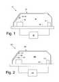
- FIG. 1is a schematic diagram of an NDIR gas sensor.
- FIG. 2is a schematic diagram of an NDIR gas sensor as may be described herein.
- FIG. 3is a side cross-sectional view of a reflective diffuser as may be used with the NDIR sensor of FIG. 2 .
- FIG. 4is an alternative embodiment of a reflective diffuser as may be used with the NDIR sensor of FIG. 2 .
- FIG. 5is an alternative embodiment of an NDIR sensor.
- FIG. 6is an alternative embodiment of an NDIR sensor.
- FIG. 7is an alternative embodiment of an NDIR sensor.
- FIG. 1shows a typical NDIR gas sensor.
- the NDIR gas sensor 10may include an infrared source 15 and an infrared detector 20 . More than one infrared detector 20 may be used.
- the infrared source 15 and the infrared detector 20may be positioned on a printed circuit board 25 .
- the infrared source 15 and the infrared detector 20may be in communication via a microprocessor 30 .
- Various types of amplifiers, filters, and other componentsalso may be used.
- the NDIR sensor 10may be enclosed by a waveguide 35 .
- the waveguide 35may define a chamber 40 extending from and enclosing in part the infrared source 15 to the infrared detector 20 .
- the waveguide 35may include one or more internal reflective surfaces 45 .
- the reflective surfaces 45typically may be smooth and may provide near specular reflection so as to minimize scattering of the light therein.
- the waveguide 35may be made from thermoplastic, metal, rubber, composite materials, and the like. If the waveguide 35 is made out of thermoplastics, for example, the injection mold for the waveguide 35 may be highly polished about the reflective surfaces 45 .
- the reflective surfaces 45then may receive a plate or coating 50 .
- the plate or coating 50may be a metal surface so as to produce a near specular reflective surface 55 . Specifically, such a near specular reflective surface 55 may maximize the signal received at the infrared detector 20 by limiting scattering.
- the infrared source 15may pulse an infrared beam within the chamber 40 .
- the beammay reflect off of the reflective surfaces 45 of the waveguide 35 and may be received by the infrared detector 20 .
- the gas within the chamber 40absorbs radiation of a known wavelength and this absorption is a measure of the concentration of the gas. Different gases have clearly defined absorption characteristics.
- the infrared detector 20thus delivers a signal proportional to the gas concentration to the microprocessor 30 . These signals then may be averaged.
- Other components and other configurationsmay be used.
- FIG. 2shows a NDIR gas sensor 100 as may be described herein. Similar to that described above, the NDIR gas sensor 100 may include an infrared source 110 and an infrared detector 120 . More than one infrared detector 120 may be used herein.
- the infrared source 110 and the infrared detector 120may be of conventional design.
- the infrared source 110 and the infrared detector 120may be positioned about a printed circuit board 130 or other type of mechanical support and/or electronic connection.
- the infrared source 110 and the infrared detector 120may be in communication via a microprocessor 140 .
- the microprocessor 140may be any type of programmable logic device. Various types of filters, amplifiers, and the like also may be used herein. Other components and other configurations may be used herein.
- the NDIR gas sensor 100also may include a waveguide 150 .
- the waveguide 150may define a chamber 160 therein extending from the infrared source 110 to the infrared detector 120 .
- the waveguide 150may be made from thermoplastics, metal, rubber, composite materials and the like.
- the waveguide 150may have any size, shape, or configuration.
- the waveguide 150may have one or more internal reflective surfaces 170 therein.
- a detector reflective surface 180may be positioned above the infrared detector 120 .
- the reflective surface 170may be in the form of a reflective diffuser 190 instead of the specular reflective surface 55 described above.
- the reflective diffuser 190may include a non-specular or a textured surface 200 .
- the textured surface 200may include a random pattern 210 .
- the textured surface 200also may include a uniform or a precision pattern 220 as is shown in exaggerated form in FIG. 4 . Any type of textured surface 200 may be used herein. Holographic patterns also may be used herein. Further, combinations of random patterns, precision patterns, holographic patterns, and the like may be used together herein.
- the injection moldmay provide the textured surface 200 as part of the mold.
- the moldthus produces a textured component 230 with the textured surface 200 .
- the surface propertieslargely may be controlled by the nature of the mold.
- the textured component 230then may be coated or plated with a reflective coat 240 to produce the reflective diffuser 190 .
- the reflective coating 240may be metallic and the like. Many other manufacturing techniques may be used herein. For example, existing components may be textured via sandpaper and the like and then coated.
- the textured surface 200 of the reflective diffuser 190is generally incorporated on a reflective surface 170 in the signal path where the majority of the infrared energy must pass.
- the detector reflective surface 180is shown in FIG. 2 adjacent to the infrared detector 120 .
- FIG. 5shows a source reflective surface 250 positioned above the infrared source 110 .
- Multiple reflective surfaces 170also may be used herein.
- the printed circuit board 130also may act as a reflective surface 170 .
- the printed circuit board 130may have a printed circuit board reflective surface 260 .
- the printed circuit board reflective surface 260may be electroplated with, for example, an electroless nickel immersion gold (“ENIG”) surface 270 .
- ENIG surface 270may be sufficiently textured so as to act as a reflective diffuser 190 .
- Other types of surfaces 270may be used.
- Other components and other configurationsmay be used herein.
- the NDIR gas sensor 100 with the reflective diffuser 190induces scattering into the infrared signal pulses produced by the infrared source 110 .
- the signals being reflected off of the textured surface 200 of the reflective diffuser 190may have more of an average and homogeneous signal intensity distribution.
- the reflective diffuser 190thus reduces overall mechanical sensitivity in the waveguide 50 , the infrared source 110 , and the infrared detector 120 such that the NDIR gas sensor 100 as a whole may have increased stability.
- the nature of the textured surface 200 of the reflective diffuser 190may be optimized for different gases and intended uses.
- the NDIR gas sensor 100 described hereinuses the textured surface 200 of the reflective diffuser 190 as a lambertian surface to induce scattering into the signal. This scattering thus optically averages the signal.
- the signal reflected off the reflective diffuser 190has more of an average and homogeneous signal intensity distribution because the reflective energy therein is diffused. The more homogeneous signal intensity distribution thus results in reduced sensitivity to mechanical changes and therefore an increase in overall stability.
- the NDIR gas sensor 100 hereinpurposefully induces such scattering for increased stability. Such an increase in stability may permit tighter accuracy specifications with lower costs.
- Other components and other configurationsmay be used herein.
- the NDIR gas sensor 100also may include multiple infrared detectors 120 .
- a first infrared detector 280 and a second infrared detector 290may be used. Any number of infrared detectors 120 may be used herein.
- the infrared detectors 280 , 290may be in physically separated different locations.
- the signal reflected by the reflective diffuser 190may result in similar energy presented to the detectors 280 , 290 .
- the reflective diffuser 190thus averages the signals to allow both detectors 280 , 290 to see similar intensity energy such that the sensor 100 may be less sensitive to mechanical changes.
Landscapes
- Physics & Mathematics (AREA)
- Spectroscopy & Molecular Physics (AREA)
- Health & Medical Sciences (AREA)
- Life Sciences & Earth Sciences (AREA)
- Chemical & Material Sciences (AREA)
- Analytical Chemistry (AREA)
- Biochemistry (AREA)
- General Health & Medical Sciences (AREA)
- General Physics & Mathematics (AREA)
- Immunology (AREA)
- Pathology (AREA)
- Investigating Or Analysing Materials By Optical Means (AREA)
Abstract
Description
Claims (19)
Priority Applications (7)
| Application Number | Priority Date | Filing Date | Title |
|---|---|---|---|
| US13/526,589US8969808B2 (en) | 2012-06-19 | 2012-06-19 | Non-dispersive infrared sensor with a reflective diffuser |
| CA2818156ACA2818156A1 (en) | 2012-06-19 | 2013-06-06 | Non-dispersive infrared sensor with a reflective diffuser |
| FI20135628AFI20135628A7 (en) | 2012-06-19 | 2013-06-06 | Non-dispersive infrared sensor with a reflective diffuser |
| JP2013125112AJP2014002146A (en) | 2012-06-19 | 2013-06-14 | Non-dispersive infrared gas sensor with reflective diffuser |
| EP13172490.8AEP2677300A3 (en) | 2012-06-19 | 2013-06-18 | Non-dispersive infrared gas sensor with a reflective diffuser |
| KR1020130069685AKR20130142940A (en) | 2012-06-19 | 2013-06-18 | Non-dispersive infrared sensor with a reflective diffuser |
| CN201310242739.9ACN103512857A (en) | 2012-06-19 | 2013-06-19 | Non-dispersive infrared gas sensor with reflective diffuser |
Applications Claiming Priority (1)
| Application Number | Priority Date | Filing Date | Title |
|---|---|---|---|
| US13/526,589US8969808B2 (en) | 2012-06-19 | 2012-06-19 | Non-dispersive infrared sensor with a reflective diffuser |
Publications (2)
| Publication Number | Publication Date |
|---|---|
| US20130334423A1 US20130334423A1 (en) | 2013-12-19 |
| US8969808B2true US8969808B2 (en) | 2015-03-03 |
Family
ID=48747315
Family Applications (1)
| Application Number | Title | Priority Date | Filing Date |
|---|---|---|---|
| US13/526,589ActiveUS8969808B2 (en) | 2012-06-19 | 2012-06-19 | Non-dispersive infrared sensor with a reflective diffuser |
Country Status (7)
| Country | Link |
|---|---|
| US (1) | US8969808B2 (en) |
| EP (1) | EP2677300A3 (en) |
| JP (1) | JP2014002146A (en) |
| KR (1) | KR20130142940A (en) |
| CN (1) | CN103512857A (en) |
| CA (1) | CA2818156A1 (en) |
| FI (1) | FI20135628A7 (en) |
Cited By (2)
| Publication number | Priority date | Publication date | Assignee | Title |
|---|---|---|---|---|
| USD764540S1 (en)* | 2014-09-26 | 2016-08-23 | Lexmark International, Inc. | Portion of a display screen with icon |
| US10161859B2 (en) | 2016-10-27 | 2018-12-25 | Honeywell International Inc. | Planar reflective ring |
Families Citing this family (12)
| Publication number | Priority date | Publication date | Assignee | Title |
|---|---|---|---|---|
| CN104122224A (en)* | 2014-08-13 | 2014-10-29 | 成都君凌科创科技有限公司 | High-precision non-dispersion infrared ray gas sensor |
| US10883875B2 (en) | 2015-03-05 | 2021-01-05 | Honeywell International Inc. | Use of selected glass types and glass thicknesses in the optical path to remove cross sensitivity to water absorption peaks |
| CN105006477B (en)* | 2015-08-04 | 2017-12-05 | 中国电子科技集团公司第十三研究所 | A kind of embedded refrigeration mode infrared focal plane detector connector of ceramics |
| FR3048084A1 (en)* | 2016-02-18 | 2017-08-25 | Commissariat Energie Atomique | NON-DISPERSIVE INFRARED SENSOR FOR DETECTING GAS. |
| DE102016003285A1 (en)* | 2016-03-18 | 2017-09-21 | Dräger Safety AG & Co. KGaA | In situ gas detection system for gas reactors with critical environments |
| CN105962524B (en)* | 2016-06-27 | 2017-09-29 | 尚妙根 | One kind massage intelligent protection footwear |
| DE102016114542A1 (en) | 2016-08-05 | 2018-02-08 | Osram Opto Semiconductors Gmbh | Detection arrangement and method for producing detection arrangements |
| US10222274B2 (en)* | 2016-09-28 | 2019-03-05 | General Electric Company | Thermographic temperature sensor |
| EP3144663B1 (en)* | 2016-11-18 | 2020-06-17 | Sensirion AG | Gas sensor module |
| US20190312186A1 (en)* | 2018-04-09 | 2019-10-10 | Microsoft Technology Licensing, Llc | Side-Emitting LED with Increased Illumination |
| US11546530B2 (en) | 2018-10-19 | 2023-01-03 | Sony Corporation | Imaging device and solid-state imaging device |
| CN110371920B (en)* | 2019-07-12 | 2023-09-08 | 北京机械设备研究所 | Method and device for inhibiting vibration sensitivity of NDIR gas sensor |
Citations (10)
| Publication number | Priority date | Publication date | Assignee | Title |
|---|---|---|---|---|
| US5341214A (en) | 1989-09-06 | 1994-08-23 | Gaztech International Corporation | NDIR gas analysis using spectral ratioing technique |
| EP0794423A1 (en) | 1996-03-06 | 1997-09-10 | Endress + Hauser Conducta Gesellschaft für Mess- und Regeltechnik mbH + Co. | Gas analyzer |
| US5834777A (en) | 1994-02-14 | 1998-11-10 | Telaire Systems, Inc. | NDIR gas sensor |
| US6410918B1 (en)* | 1997-10-28 | 2002-06-25 | Edwards Systems Technology, Inc. | Diffusion-type NDIR gas analyzer with improved response time due to convection flow |
| US6469303B1 (en)* | 2000-05-17 | 2002-10-22 | Rae Systems, Inc. | Non-dispersive infrared gas sensor |
| US20060256415A1 (en) | 2000-12-15 | 2006-11-16 | De La Rue International Limited | Diffuse reflector and method |
| US20070017458A1 (en) | 2005-07-13 | 2007-01-25 | Robert Frodl | Gas Sensor Assembly and Measurement Method With Early Warning Means |
| US20090039267A1 (en) | 2004-09-13 | 2009-02-12 | Michael Arndt | Reflector module for a photometric gas sensor |
| US7541587B2 (en) | 2003-12-02 | 2009-06-02 | City Technology Limited | Gas sensor |
| US20100078563A1 (en) | 2008-09-30 | 2010-04-01 | Heikki Haveri | Simplified beam splitter for ir gas sensor |
- 2012
- 2012-06-19USUS13/526,589patent/US8969808B2/enactiveActive
- 2013
- 2013-06-06FIFI20135628Apatent/FI20135628A7/ennot_activeApplication Discontinuation
- 2013-06-06CACA2818156Apatent/CA2818156A1/ennot_activeAbandoned
- 2013-06-14JPJP2013125112Apatent/JP2014002146A/enactivePending
- 2013-06-18KRKR1020130069685Apatent/KR20130142940A/ennot_activeWithdrawn
- 2013-06-18EPEP13172490.8Apatent/EP2677300A3/ennot_activeWithdrawn
- 2013-06-19CNCN201310242739.9Apatent/CN103512857A/enactivePending
Patent Citations (11)
| Publication number | Priority date | Publication date | Assignee | Title |
|---|---|---|---|---|
| US5341214A (en) | 1989-09-06 | 1994-08-23 | Gaztech International Corporation | NDIR gas analysis using spectral ratioing technique |
| US5834777A (en) | 1994-02-14 | 1998-11-10 | Telaire Systems, Inc. | NDIR gas sensor |
| EP0794423A1 (en) | 1996-03-06 | 1997-09-10 | Endress + Hauser Conducta Gesellschaft für Mess- und Regeltechnik mbH + Co. | Gas analyzer |
| US5874737A (en) | 1996-03-06 | 1999-02-23 | Endress + Hauser Conducta Gesellschaft fur Mess- und Regeltechnik mbH + Co. | Gas analyzer |
| US6410918B1 (en)* | 1997-10-28 | 2002-06-25 | Edwards Systems Technology, Inc. | Diffusion-type NDIR gas analyzer with improved response time due to convection flow |
| US6469303B1 (en)* | 2000-05-17 | 2002-10-22 | Rae Systems, Inc. | Non-dispersive infrared gas sensor |
| US20060256415A1 (en) | 2000-12-15 | 2006-11-16 | De La Rue International Limited | Diffuse reflector and method |
| US7541587B2 (en) | 2003-12-02 | 2009-06-02 | City Technology Limited | Gas sensor |
| US20090039267A1 (en) | 2004-09-13 | 2009-02-12 | Michael Arndt | Reflector module for a photometric gas sensor |
| US20070017458A1 (en) | 2005-07-13 | 2007-01-25 | Robert Frodl | Gas Sensor Assembly and Measurement Method With Early Warning Means |
| US20100078563A1 (en) | 2008-09-30 | 2010-04-01 | Heikki Haveri | Simplified beam splitter for ir gas sensor |
Non-Patent Citations (4)
| Title |
|---|
| Electroless nickel immersion gold, Wikipedia, Apr. 2, 2012, p. 1. |
| European Search Report dated Jan. 8, 2014 issue in European Patent Application No. 13172490.8. |
| Hodgkinson et al., Gas cells for tunable diode laser absorption spectroscopy employing optical diffusers. Part 1: Single and dual pass cells, 2009, 7th International Conference on Tunable Diode Laser Spectroscopy, pp. 1-25, online at https://dspace.lib.cranfield.ac.uk/bitstream/1826/4763/3/Gas-cells-for-tunable-diode-laser-absorption-pt1.pdf.* |
| Hodgkinson et al., Gas cells for tunable diode laser absorption spectroscopy employing optical diffusers. Part 1: Single and dual pass cells, 2009, 7th International Conference on Tunable Diode Laser Spectroscopy, pp. 1-25, online at https://dspace.lib.cranfield.ac.uk/bitstream/1826/4763/3/Gas—cells—for—tunable—diode—laser—absorption-pt1.pdf.* |
Cited By (2)
| Publication number | Priority date | Publication date | Assignee | Title |
|---|---|---|---|---|
| USD764540S1 (en)* | 2014-09-26 | 2016-08-23 | Lexmark International, Inc. | Portion of a display screen with icon |
| US10161859B2 (en) | 2016-10-27 | 2018-12-25 | Honeywell International Inc. | Planar reflective ring |
Also Published As
| Publication number | Publication date |
|---|---|
| JP2014002146A (en) | 2014-01-09 |
| CA2818156A1 (en) | 2013-12-19 |
| KR20130142940A (en) | 2013-12-30 |
| EP2677300A2 (en) | 2013-12-25 |
| EP2677300A3 (en) | 2014-01-29 |
| US20130334423A1 (en) | 2013-12-19 |
| FI20135628L (en) | 2013-12-20 |
| FI20135628A7 (en) | 2013-12-20 |
| CN103512857A (en) | 2014-01-15 |
Similar Documents
| Publication | Publication Date | Title |
|---|---|---|
| US8969808B2 (en) | Non-dispersive infrared sensor with a reflective diffuser | |
| US4278353A (en) | Optical inspection of gold surfaces | |
| US20160313244A1 (en) | Optical sensing apparatus provided with light source and light detector | |
| CN103415757B (en) | For the one-sided infrared sensor of the thickness or weight of measuring the product comprising reflection horizon | |
| KR101786133B1 (en) | System and method for detection and measurement of interfacial properties in single and multilayer objects | |
| US20080239322A1 (en) | Optical absorption gas sensor | |
| CN101865840A (en) | Surface plasmon resonance imaging sensing system | |
| US6822215B2 (en) | Optoelectronic sensor including a transparent optode material | |
| WO2012005350A1 (en) | Nondestructive measuring device for green grocery | |
| TW201333447A (en) | Detector | |
| KR20120137292A (en) | Measuring method and measuring apparatus for determining transmission and/or reflection properties | |
| CN111936049A (en) | Measurement system for spectroscopic biopsy | |
| US11921031B2 (en) | Compact gas sensor | |
| KR102246452B1 (en) | Non-dispersive Infra Red(NDIR) gas sensor and manufacturing method thereof | |
| EP2823287A1 (en) | Enhanced surface plasmon resonance method | |
| CN110637225A (en) | Optical sensor | |
| HK1192615A (en) | Non-dispersive infrared sensor with a reflective diffuser | |
| US20060012795A1 (en) | Method of determining surface plasmon resonances at two-dimensional measurement surfaces | |
| CN220872339U (en) | Optical path transmission structure | |
| US9188528B2 (en) | Sensor for monitoring a medium | |
| CN102947689B (en) | light unit | |
| EP2573546A1 (en) | Gas sensor | |
| KR102223821B1 (en) | Multi gas sensing apparatus | |
| CN207779902U (en) | Raman spectrum detection device based on reflected optical power | |
| CN206594055U (en) | Moisture content determining device |
Legal Events
| Date | Code | Title | Description |
|---|---|---|---|
| AS | Assignment | Owner name:GENERAL ELECTRIC COMPANY, NEW YORK Free format text:ASSIGNMENT OF ASSIGNORS INTEREST;ASSIGNOR:HENDERSON, DAVID BENJAMIN;REEL/FRAME:028398/0482 Effective date:20120614 | |
| AS | Assignment | Owner name:AMPHENOL CORPORATION, CONNECTICUT Free format text:ASSIGNMENT OF ASSIGNORS INTEREST;ASSIGNOR:GENERAL ELECTRIC COMPANY;REEL/FRAME:031842/0049 Effective date:20131218 | |
| AS | Assignment | Owner name:GE THERMOMETRICS, INC., PENNSYLVANIA Free format text:ASSIGNMENT OF ASSIGNORS INTEREST;ASSIGNOR:AMPHENOL CORPORATION;REEL/FRAME:032745/0924 Effective date:20131218 | |
| AS | Assignment | Owner name:AMPHENOL THERMOMETRICS, INC., PENNSYLVANIA Free format text:CHANGE OF NAME;ASSIGNOR:GE THERMOMETRICS, INC.;REEL/FRAME:032763/0141 Effective date:20131219 | |
| STCF | Information on status: patent grant | Free format text:PATENTED CASE | |
| MAFP | Maintenance fee payment | Free format text:PAYMENT OF MAINTENANCE FEE, 4TH YEAR, LARGE ENTITY (ORIGINAL EVENT CODE: M1551); ENTITY STATUS OF PATENT OWNER: LARGE ENTITY Year of fee payment:4 | |
| MAFP | Maintenance fee payment | Free format text:PAYMENT OF MAINTENANCE FEE, 8TH YEAR, LARGE ENTITY (ORIGINAL EVENT CODE: M1552); ENTITY STATUS OF PATENT OWNER: LARGE ENTITY Year of fee payment:8 |