US8968402B2 - ACL implants, instruments, and methods - Google Patents
ACL implants, instruments, and methodsDownload PDFInfo
- Publication number
- US8968402B2 US8968402B2US13/655,186US201213655186AUS8968402B2US 8968402 B2US8968402 B2US 8968402B2US 201213655186 AUS201213655186 AUS 201213655186AUS 8968402 B2US8968402 B2US 8968402B2
- Authority
- US
- United States
- Prior art keywords
- ligament graft
- tool
- graft
- ligament
- tension force
- Prior art date
- Legal status (The legal status is an assumption and is not a legal conclusion. Google has not performed a legal analysis and makes no representation as to the accuracy of the status listed.)
- Active, expires
Links
- 238000000034methodMethods0.000titleabstractdescription35
- 239000007943implantSubstances0.000titleabstractdescription10
- 210000003041ligamentAnatomy0.000claimsabstractdescription134
- 230000007246mechanismEffects0.000claimsdescription7
- 210000000988bone and boneAnatomy0.000abstractdescription75
- 210000001264anterior cruciate ligamentAnatomy0.000abstractdescription61
- 230000001054cortical effectEffects0.000abstractdescription41
- 210000003127kneeAnatomy0.000description22
- 210000002967posterior cruciate ligamentAnatomy0.000description14
- 238000003780insertionMethods0.000description12
- 230000037431insertionEffects0.000description12
- 210000002303tibiaAnatomy0.000description12
- 210000004872soft tissueAnatomy0.000description10
- 210000002435tendonAnatomy0.000description10
- 210000000689upper legAnatomy0.000description10
- 230000008439repair processEffects0.000description8
- 229920000642polymerPolymers0.000description5
- 238000001356surgical procedureMethods0.000description5
- 230000035876healingEffects0.000description4
- 210000002414legAnatomy0.000description4
- 229910052751metalInorganic materials0.000description4
- 239000002184metalSubstances0.000description4
- 230000002093peripheral effectEffects0.000description4
- 210000004763bicuspidAnatomy0.000description3
- 230000006835compressionEffects0.000description3
- 238000007906compressionMethods0.000description3
- 239000004744fabricSubstances0.000description3
- 230000000284resting effectEffects0.000description3
- 239000004696Poly ether ether ketoneSubstances0.000description2
- 230000006978adaptationEffects0.000description2
- 230000008901benefitEffects0.000description2
- 239000000919ceramicSubstances0.000description2
- 239000002131composite materialSubstances0.000description2
- 238000005520cutting processMethods0.000description2
- 230000009977dual effectEffects0.000description2
- 230000006870functionEffects0.000description2
- 238000007373indentationMethods0.000description2
- 238000004519manufacturing processMethods0.000description2
- 239000000463materialSubstances0.000description2
- 238000012986modificationMethods0.000description2
- 230000004048modificationEffects0.000description2
- 229920002530polyetherether ketonePolymers0.000description2
- 230000008569processEffects0.000description2
- 239000012858resilient materialSubstances0.000description2
- 239000007787solidSubstances0.000description2
- 210000001519tissueAnatomy0.000description2
- 206010060872Transplant failureDiseases0.000description1
- 208000027418Wounds and injuryDiseases0.000description1
- 210000001361achilles tendonAnatomy0.000description1
- 239000000956alloySubstances0.000description1
- 229910045601alloyInorganic materials0.000description1
- 210000003423ankleAnatomy0.000description1
- 230000009286beneficial effectEffects0.000description1
- 230000002146bilateral effectEffects0.000description1
- 239000000560biocompatible materialSubstances0.000description1
- 230000006378damageEffects0.000description1
- 239000003814drugSubstances0.000description1
- 230000000694effectsEffects0.000description1
- 210000001513elbowAnatomy0.000description1
- 239000000835fiberSubstances0.000description1
- 210000003811fingerAnatomy0.000description1
- 210000002683footAnatomy0.000description1
- 239000011521glassSubstances0.000description1
- 210000004247handAnatomy0.000description1
- 208000014674injuryDiseases0.000description1
- 210000000629knee jointAnatomy0.000description1
- 230000007774longtermEffects0.000description1
- 238000010197meta-analysisMethods0.000description1
- 150000002739metalsChemical class0.000description1
- 230000000399orthopedic effectEffects0.000description1
- 210000000426patellar ligamentAnatomy0.000description1
- 230000008447perceptionEffects0.000description1
- 230000002085persistent effectEffects0.000description1
- 239000004033plasticSubstances0.000description1
- 229920003023plasticPolymers0.000description1
- 230000002980postoperative effectEffects0.000description1
- 238000002360preparation methodMethods0.000description1
- 238000012552reviewMethods0.000description1
- 238000010079rubber tappingMethods0.000description1
- 238000007493shaping processMethods0.000description1
- 238000004904shorteningMethods0.000description1
- 210000002832shoulderAnatomy0.000description1
- 238000012360testing methodMethods0.000description1
- 229940124597therapeutic agentDrugs0.000description1
- 238000013519translationMethods0.000description1
- 230000003245working effectEffects0.000description1
- 210000000707wristAnatomy0.000description1
Images


Classifications
- A—HUMAN NECESSITIES
- A61—MEDICAL OR VETERINARY SCIENCE; HYGIENE
- A61F—FILTERS IMPLANTABLE INTO BLOOD VESSELS; PROSTHESES; DEVICES PROVIDING PATENCY TO, OR PREVENTING COLLAPSING OF, TUBULAR STRUCTURES OF THE BODY, e.g. STENTS; ORTHOPAEDIC, NURSING OR CONTRACEPTIVE DEVICES; FOMENTATION; TREATMENT OR PROTECTION OF EYES OR EARS; BANDAGES, DRESSINGS OR ABSORBENT PADS; FIRST-AID KITS
- A61F2/00—Filters implantable into blood vessels; Prostheses, i.e. artificial substitutes or replacements for parts of the body; Appliances for connecting them with the body; Devices providing patency to, or preventing collapsing of, tubular structures of the body, e.g. stents
- A61F2/02—Prostheses implantable into the body
- A61F2/08—Muscles; Tendons; Ligaments
- A61F2/0811—Fixation devices for tendons or ligaments
- A—HUMAN NECESSITIES
- A61—MEDICAL OR VETERINARY SCIENCE; HYGIENE
- A61B—DIAGNOSIS; SURGERY; IDENTIFICATION
- A61B17/00—Surgical instruments, devices or methods
- A61B17/16—Instruments for performing osteoclasis; Drills or chisels for bones; Trepans
- A61B17/17—Guides or aligning means for drills, mills, pins or wires
- A61B17/1714—Guides or aligning means for drills, mills, pins or wires for applying tendons or ligaments
- A—HUMAN NECESSITIES
- A61—MEDICAL OR VETERINARY SCIENCE; HYGIENE
- A61F—FILTERS IMPLANTABLE INTO BLOOD VESSELS; PROSTHESES; DEVICES PROVIDING PATENCY TO, OR PREVENTING COLLAPSING OF, TUBULAR STRUCTURES OF THE BODY, e.g. STENTS; ORTHOPAEDIC, NURSING OR CONTRACEPTIVE DEVICES; FOMENTATION; TREATMENT OR PROTECTION OF EYES OR EARS; BANDAGES, DRESSINGS OR ABSORBENT PADS; FIRST-AID KITS
- A61F2/00—Filters implantable into blood vessels; Prostheses, i.e. artificial substitutes or replacements for parts of the body; Appliances for connecting them with the body; Devices providing patency to, or preventing collapsing of, tubular structures of the body, e.g. stents
- A61F2/02—Prostheses implantable into the body
- A61F2/08—Muscles; Tendons; Ligaments
- A61F2/0805—Implements for inserting tendons or ligaments
- A—HUMAN NECESSITIES
- A61—MEDICAL OR VETERINARY SCIENCE; HYGIENE
- A61F—FILTERS IMPLANTABLE INTO BLOOD VESSELS; PROSTHESES; DEVICES PROVIDING PATENCY TO, OR PREVENTING COLLAPSING OF, TUBULAR STRUCTURES OF THE BODY, e.g. STENTS; ORTHOPAEDIC, NURSING OR CONTRACEPTIVE DEVICES; FOMENTATION; TREATMENT OR PROTECTION OF EYES OR EARS; BANDAGES, DRESSINGS OR ABSORBENT PADS; FIRST-AID KITS
- A61F2/00—Filters implantable into blood vessels; Prostheses, i.e. artificial substitutes or replacements for parts of the body; Appliances for connecting them with the body; Devices providing patency to, or preventing collapsing of, tubular structures of the body, e.g. stents
- A61F2/02—Prostheses implantable into the body
- A61F2/08—Muscles; Tendons; Ligaments
- A61F2/0811—Fixation devices for tendons or ligaments
- A61F2002/0817—Structure of the anchor
- A61F2002/0823—Modular anchors comprising a plurality of separate parts
- A61F2002/0835—Modular anchors comprising a plurality of separate parts with deformation of anchor parts, e.g. expansion of dowel by set screw
- A—HUMAN NECESSITIES
- A61—MEDICAL OR VETERINARY SCIENCE; HYGIENE
- A61F—FILTERS IMPLANTABLE INTO BLOOD VESSELS; PROSTHESES; DEVICES PROVIDING PATENCY TO, OR PREVENTING COLLAPSING OF, TUBULAR STRUCTURES OF THE BODY, e.g. STENTS; ORTHOPAEDIC, NURSING OR CONTRACEPTIVE DEVICES; FOMENTATION; TREATMENT OR PROTECTION OF EYES OR EARS; BANDAGES, DRESSINGS OR ABSORBENT PADS; FIRST-AID KITS
- A61F2/00—Filters implantable into blood vessels; Prostheses, i.e. artificial substitutes or replacements for parts of the body; Appliances for connecting them with the body; Devices providing patency to, or preventing collapsing of, tubular structures of the body, e.g. stents
- A61F2/02—Prostheses implantable into the body
- A61F2/08—Muscles; Tendons; Ligaments
- A61F2/0811—Fixation devices for tendons or ligaments
- A61F2002/0847—Mode of fixation of anchor to tendon or ligament
- A61F2002/0852—Fixation of a loop or U-turn, e.g. eyelets, anchor having multiple holes
- A—HUMAN NECESSITIES
- A61—MEDICAL OR VETERINARY SCIENCE; HYGIENE
- A61F—FILTERS IMPLANTABLE INTO BLOOD VESSELS; PROSTHESES; DEVICES PROVIDING PATENCY TO, OR PREVENTING COLLAPSING OF, TUBULAR STRUCTURES OF THE BODY, e.g. STENTS; ORTHOPAEDIC, NURSING OR CONTRACEPTIVE DEVICES; FOMENTATION; TREATMENT OR PROTECTION OF EYES OR EARS; BANDAGES, DRESSINGS OR ABSORBENT PADS; FIRST-AID KITS
- A61F2/00—Filters implantable into blood vessels; Prostheses, i.e. artificial substitutes or replacements for parts of the body; Appliances for connecting them with the body; Devices providing patency to, or preventing collapsing of, tubular structures of the body, e.g. stents
- A61F2/02—Prostheses implantable into the body
- A61F2/08—Muscles; Tendons; Ligaments
- A61F2/0811—Fixation devices for tendons or ligaments
- A61F2002/0847—Mode of fixation of anchor to tendon or ligament
- A61F2002/0858—Fixation of tendon or ligament between anchor and bone, e.g. interference screws, wedges
- A—HUMAN NECESSITIES
- A61—MEDICAL OR VETERINARY SCIENCE; HYGIENE
- A61F—FILTERS IMPLANTABLE INTO BLOOD VESSELS; PROSTHESES; DEVICES PROVIDING PATENCY TO, OR PREVENTING COLLAPSING OF, TUBULAR STRUCTURES OF THE BODY, e.g. STENTS; ORTHOPAEDIC, NURSING OR CONTRACEPTIVE DEVICES; FOMENTATION; TREATMENT OR PROTECTION OF EYES OR EARS; BANDAGES, DRESSINGS OR ABSORBENT PADS; FIRST-AID KITS
- A61F2/00—Filters implantable into blood vessels; Prostheses, i.e. artificial substitutes or replacements for parts of the body; Appliances for connecting them with the body; Devices providing patency to, or preventing collapsing of, tubular structures of the body, e.g. stents
- A61F2/02—Prostheses implantable into the body
- A61F2/08—Muscles; Tendons; Ligaments
- A61F2/0811—Fixation devices for tendons or ligaments
- A61F2002/0876—Position of anchor in respect to the bone
- A61F2002/0888—Anchor in or on a blind hole or on the bone surface without formation of a tunnel
- A—HUMAN NECESSITIES
- A61—MEDICAL OR VETERINARY SCIENCE; HYGIENE
- A61F—FILTERS IMPLANTABLE INTO BLOOD VESSELS; PROSTHESES; DEVICES PROVIDING PATENCY TO, OR PREVENTING COLLAPSING OF, TUBULAR STRUCTURES OF THE BODY, e.g. STENTS; ORTHOPAEDIC, NURSING OR CONTRACEPTIVE DEVICES; FOMENTATION; TREATMENT OR PROTECTION OF EYES OR EARS; BANDAGES, DRESSINGS OR ABSORBENT PADS; FIRST-AID KITS
- A61F2250/00—Special features of prostheses classified in groups A61F2/00 - A61F2/26 or A61F2/82 or A61F9/00 or A61F11/00 or subgroups thereof
- A61F2250/0004—Special features of prostheses classified in groups A61F2/00 - A61F2/26 or A61F2/82 or A61F9/00 or A61F11/00 or subgroups thereof adjustable
- A61F2250/0007—Special features of prostheses classified in groups A61F2/00 - A61F2/26 or A61F2/82 or A61F9/00 or A61F11/00 or subgroups thereof adjustable for adjusting length
Definitions
- the present disclosurerelates to anterior cruciate ligament (ACL) repair surgery. More precisely, the present invention relates to implants, systems, methods of use and instruments for double bundle ACL repair, including securing an ACL graft with a cortical fixation device and separating the graft into multiple bundles with an aperture fixation device so as to approximate the natural bundles of an intact ACL.
- the systems, apparatus, and methods disclosed hereinmay be applicable to tibial or femoral fixation of a doubled hamstring tendon graft. It is contemplated that the systems and methods set forth herein, or adaptations, may be useful in suspensory fixation applications beyond anterior cruciate ligament repair.
- BPTBbone-patellar tendon-bone
- HThamstring tendon
- QTquadriceps tendon
- Allograftswhich are harvested from a donor, may comprise patellar tendon, quadriceps tendon, Achilles tendon, tibialis anterior tendon, hamstring tendons, or occasionally peroneal tendons. Any of these grafts may be placed so that it traverses the intercondylar notch and its ends rest within tibial and femoral bone tunnels.
- Tibial and femoral bone tunnel placementhas been a very controversial topic.
- Anterior placement of the femoral tunnelhas become generally accepted as a technical cause of graft failure.
- Recently, after years of transtibial placement of the femoral bone tunnelit has become increasingly popular to drill the femoral tunnel separately (i.e., through a medial arthroscopic portal). This may result in more anatomic placement of the femoral tunnel and improved graft orientation.
- Soft tissue graft fixationcan be broadly divided into interference screw-based fixation, cortical fixation, and cross pin fixation.
- Interference screw-based fixation of soft tissue graftsmay be used in the femur and tibia. This type of fixation generates friction between the graft and the bone tunnel. Many surgeons who were originally trained in BPTB grafts continue to use this method of fixation when they use soft tissue grafts. Metal and bioabsorbable interference screws are currently available. However, there are no interference screws that have demonstrated bony ingrowth, which would be beneficial over the long term.
- Cortical fixationmay be preferred by surgeons who primarily use soft tissue grafts.
- a number of devicesare known to take advantage of the innate strength of cortical bone.
- German surgeon Helmut Brucknerdescribed an ACL reconstruction technique in which a BPTB graft was secured by sutures to a button resting on the lateral aspect of the lateral femoral condyle.
- Other examples of cortical fixation devicesinclude EndobuttonTM (Smith and Nephew) and EZLocTM (Biomet).
- Cortical fixation deviceshave been shown to have some of the highest pullout strengths of any soft tissue graft fixation device. In the femur, these devices may comprise an extracortical anchor attached to a fabric or suture loop.
- Such a devicemay be used by draping the graft over the fabric loop, supporting the anchor against the exterior cortical surface so that the graft is suspended within the tunnel, and securing the fabric loop to the anchor.
- cortical fixationmay be achieved by stitching sutures to the free ends of the graft, placing a screw through the anterior tibial cortex, tying the sutures around the screw, and compressing the sutures against the cortex with a washer.
- Cross-pin fixationhas been gaining in popularity, at least in part because of the perception that it may provide secure fixation closer to the tunnel aperture than that provided by cortical fixation.
- Cross-pin fixationmay be achieved by passing a pin across a bone tunnel close to the aperture and draping the graft over the pin where it crosses the tunnel.
- aperture fixationprovides greater stability than does cortical fixation
- This theorypresumes that an ACL reconstruction spanning a longer distance between fixation points will have greater elasticity than an ACL reconstruction spanning a shorter distance. Fixation closer to the joint space may provide higher stability than remote fixation at the cortex because the distance across the joint space is much less than the distance between extracortical fixation points.
- a 2005 meta-analysis of stability after ACL reconstructionshowed cortical fixation to be associated with the highest rates of ACL reconstruction stability for soft tissue grafts.
- aperture fixationmay lead to increased graft stiffness.
- distal cortical fixation of a soft tissue ACL graftmay be stronger, stiffer, and more slip resistant than is aperture fixation with an interference screw alone.
- the use of an interference screw alonemay cause tunnel widening and may prevent circumferential tendon-tunnel healing, which may result in inferior strength and stiffness at 4 weeks compared with cortical fixation.
- the insertion of a bone dowel alongside a tendon graft in the tunnel, in conjunction with distal cortical fixationmay prevent tunnel widening, increase stiffness, promote circumferential healing, and simplify revision surgery.
- Aggressive, brace-free rehabilitation with early weight bearingmay be safe following high-stiffness, slip-resistant fixation.
- the high stiffness provided by distal cortical fixationmay reduce the graft tension required to restore stability and may lower graft tension during open-chain exercise. Reducing the graft tension without increasing anterior laxity requires high-stiffness fixation which also resists slipping and tension loss during aggressive rehabilitation.
- Whipstitch-post tibial cortical fixationwas the first fixation method used successfully for quadrupled hamstring grafts. Simple interference screw fixation has had mixed results, while interference screw fixation combined with cortical fixation has shown very good results.
- interference screw-based methodssuch as the IntrafixTM (DePuy Mitek) appear to be promising constructs on the tibial side.
- IntrafixTMDePuy Mitek
- cross-pin fixation on the tibial sidemay be popular among surgeons, there is a paucity of clinical data pertaining to it, and the clinical series that have been published to date have shown mixed results.
- the ACLhas two functional bundles: the anteromedial (AM) bundle and the posterolateral (PL) bundle.
- the bundlesare named according to their tibial insertion sites.
- the AM and PL bundlesare parallel to each other and are oriented generally along the mechanical axis of the leg.
- the AM and PL bundlesare crossed. This occurs because the PL bundle femoral insertion site is posterior to the AM bundle femoral insertion site when the knee is in extension, and anterior to the AM bundle femoral insertion site when the knee is flexed to 90 degrees.
- the AM bundle femoral insertion siterotates over the PL bundle femoral insertion site as the knee flexes.
- each bundlemakes a unique contribution to knee kinematics at different knee flexion angles.
- the PL bundletightens and the AM bundle relaxes, whereas in flexion, the AM bundle tightens as the ⁇ L bundle becomes lax.
- the AM bundleis the primary restraint against anterior tibial translation and the PL bundle tends to stabilize the knee in full extension, particularly against rotational loads.
- Anatomic double bundle ACL reconstructionhas some logical rationales in its favor and is supported by biomechanical studies. These studies suggest that conventional single bundle ACL reconstruction may successfully restore anteroposterior knee stability, but the reconstructed knee may be unable to resist combined rotatory loads. Cadaveric studies of double bundle knee reconstructions reveal a closer restoration of normal knee kinematics and better rotational stability. A closer restoration of normal knee kinematics may be associated with improved functional outcomes following ACL reconstruction.
- Reciprocal tensile behaviorhas long been a quest of the surgeon who performs ACL reconstructions and has been a rationale for pursuing the double bundle technique.
- the conceptis that the AM bundle should carry more tension in flexion and the PL bundle should carry more tension in extension.
- a doubled-over soft tissue graft in a single tunnelmay restore reciprocal tensile behavior if the tunnel has been placed to avoid PCL and roof impingement and the centers of the graft bundles can be separated and appropriately oriented at the femoral and tibial tunnel apertures.
- Double bundle ACL reconstructionis not without its challenges.
- the most common cause of failure of any kind of ACL reconstructionis improper bone tunnel position.
- the double bundle procedurewhich is more complex than the single bundle technique, has more risk of misplaced bone tunnels.
- dual tunnelscan interfere with each other when they are not meticulously positioned.
- a poorly positioned PL tunnelmay displace a subsequently formed AM tunnel too far anteriorly, resulting in roof impingement and potential graft rupture.
- the double bundle procedurehas other potential challenges.
- the greater complexity of double bundle repairmay result in longer surgical time.
- Two separate graftsneed to be prepared, four tunnels need to be prepared, and four separate fixation devices are required.
- Suitable femoral fixation optionsmay be limited.
- the EndoButtonTMmay be the most common femoral fixation device for a double bundle ACL reconstruction due to its low profile.
- Cross-pin femoral fixationmay not be feasible for double bundle ACL reconstruction due to anatomical constraints in the vicinity of the femoral tunnel apertures.
- a larger tibial footprint of a double bundle ACL reconstructionmay offer greater potential for femoral notch impingement by the graft.
- Larger cross-sectional areas of graft tissuecan traverse the intercondylar notch in a double bundle ACL reconstruction. This may result in PCL impingement as well as notch impingement due to the size of the grafts.
- PCL impingementhas been seen even in single bundle ACL reconstructions. PCL impingement may occur when the tibial tunnel is placed in a vertical orientation at an angle >70 degrees from the medial joint line of the tibia and the femoral tunnel is then drilled through the tibial tunnel.
- the composite areamay extend outside the border of the anatomic ACL footprint. This effectively increases the cross-sectional area of the graft and “overstuffs the notch.” Furthermore, the cross-sectional area of the native ACL as it crosses the PCL is approximately 54.4 square mm, and may be significantly less in smaller people. Therefore, if double bundle ACL reconstruction with a standard size graft is performed with dual femoral and tibial tunnels, the effective cross-sectional area of the graft may exceed 100 square mm. Notch or PCL impingement, loss of knee flexion and eventual stretching and failure of the tissue may result.
- ACL reconstruction techniquethat produces bone tunnels that more closely replicate the anatomic femoral and tibial ACL footprints, uses a single graft separated into bundles to restore the kinematics of the native ACL, and eliminates the problems of increased surgical time and complexity, difficult revision, notch impingement and PCL impingement that are inherent with the current double tunnel, double bundle ACL technique.
- fixation implantthat can be used to deliver specific therapeutic agents, such as biochemicals that allow for tendon to bone healing or enhance osteoinductivity such that bone may grow into the fixation implant.
- FIG. 1is a perspective view of a surgical tool 1 for inserting a tensioned ligament into a patient;
- FIG. 2is a cross-sectional side view of the handle portion 2 of the surgical tool 1 of FIG. 1 with the cross-sectional plane taken parallel to the two attachment members 4 , 6 along their greatest width;
- FIG. 3is a cross-sectional side view of the handle portion 2 of the surgical tool 1 of FIG. 1 with the cross-sectional plane taken between the two attachment members 4 , 6 and normal to the cross-sectional plane of FIG. 2 ;
- FIG. 4is a perspective view of the proximal handle portion 2 with the twist knob removed;
- FIG. 5Ais a perspective view of a ligament fixation system
- FIG. 5Bis a perspective view of another ligament fixation system
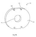
- FIG. 6Ais a perspective view of a fixation device
- FIG. 6Bis another perspective view of the fixation device of FIG. 6A from a different angle
- FIG. 6Cis a perspective view of another fixation system
- FIG. 6Dis another perspective view of the fixation system of FIG. 6C in an expanded configuration
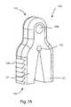
- FIG. 7Ais a perspective view of another fixation device; and FIG. 7B is a perspective view of the fixation device of FIG. 7A in an expanded configuration;
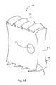
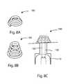
- FIG. 8Ais a perspective view of yet another fixation device
- FIG. 8Bis a perspective view of the fixation device of FIG. 8B in an uncoiled configuration
- FIG. 8Cis a side cross sectional view of the fixation device of FIG. 8A in an fixation system with a graft suspended in a bone tunnel;
- FIG. 9Ais a perspective view of yet another fixation system
- FIG. 9Bis a perspective view of yet another fixation system
- FIG. 9Cis a perspective view of yet another fixation system
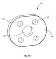
- FIG. 10Ais a side view of yet another fixation system
- FIG. 10Bis a perspective view of the fixation system of FIG. 10A ;
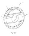
- FIG. 11Ais a perspective view of yet another fixation system
- FIG. 11Bis a perspective view of the fixation system of FIG. 11A in an expanded configuration
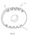
- FIG. 12Ais a top view of yet another fixation device
- FIG. 12Bis a top view of yet another fixation device
- FIG. 12Cis a top view of yet another fixation device
- FIG. 13is a perspective view of a tamp tool
- FIG. 14is a perspective view of another tamp tool.
- FIG. 15is a perspective view of a double drill guide.
- Superiormeans toward the head. Inferior means away from the head. Anterior means toward the front. Posterior means toward the back. Medial means toward the midline, or plane of bilateral symmetry, of the body. Lateral means away from the midline of the body. Proximal means toward the trunk of the body, or toward the user. Distal means away from the trunk of the body, or away from the user.
- a sagittal planedivides a body into bilaterally symmetric right and left portions.
- a coronal planedivides a body into anterior and posterior portions.
- a transverse planedivides a body into superior and inferior portions.
- the systems, methods, and devices described hereinmay improve a surgeon's likelihood of matching an ACL graft to a natural ACL attachment area on a femur or tibia; improve graft fixation; reduce surgical time; and improve clinical outcomes.
- the terms “engaged,” “engaged with,” “coupled,” or “coupled to,”can mean that the one or more structures are engaged (or coupled) with each other either directly, or through one or more intermediate members.
- ligamentor “ligament graft” as used herein, include any type of ligament graft including, but not limited to: any artificial ligament graft, natural ligament graft, allograft, autograft, xenograft, tendon, etc.
- FIGS. 1-4show various views of a surgical tool 1 that facilitates both the preparation and insertion of a ligament graft 10 into a patient.
- the surgical tool 1can apply tension to the ligament graft 10 to keep the ligament graft 10 straight and close to a shaft, or elongate member 12 of the surgical tool 1 to help facilitate insertion of the ligament graft 10 into the patient.
- the surgical tool 1can also help prepare the ligament graft 10 for insertion into the patient by applying a tension force to the ligament graft 10 to help “exercise” the ligament graft 10 prior to insertion.
- Exercising or “pre-stretching” a ligament graftreduces the likelihood of post-operative ligament creep.
- Ligament creepis the undesirable lengthening or “stretching-out” of the ligament graft after it is has been implanted in the patient.
- the surgeonwill typically exercise the ligament graft by applying a constant tension force to the ligament graft for a period of time sufficiently long enough to stretch out the ligament such that any additional stretching results in little or no lengthening of the ligament.
- the surgeonwill stretch out the ligament with one device, remove the ligament from the stretching device, and then use a second device to insert the ligament into the patient.
- the surgical tool 1 shown in FIGS. 1-4eliminates these problems by providing a single tool 1 that can be used to both exercise the ligament graft and insert the ligament graft into the patient while maintaining the ligament graft under tension throughout the entire procedure.
- FIG. 1shows the surgical tool 1 holding a ligament 10 under tension.
- a fixation device, or aperture plug 14is attached to the distal end of elongate member 12 .
- the ligament 10can be wrapped around the aperture plug 14 and connected to attachment members 4 , 6 through sutures 20 , 22 engaged with each end of the ligament 10 .
- Tension forces applied to the ligament 10can be increased by rotating a twist knob 8 in a first direction causing the shaft 12 to move in the distal direction and stretching the ligament 10 .
- Tension forces applied to the ligamentcan also be reduced by rotating the twist knob 8 in a second direction causing the shaft 12 to move in the proximal direction allowing the ligament 10 to relax.
- the aperture plug 14is also connected to a cortical fixation system which includes a cortical fixation member 16 and at least one connector 18 .
- the distal end of the elongate member 12can have a fixation device attachment feature (not shown) adapted to receive the fixation device 14 , such as a protrusion configured for insertion into an aperture formed in the fixation device 14 .
- the fixation device attachment featurecan be threading formed on the elongate member 12 with complimentary shaped threading formed in the plug 14 .
- the elongate member 12has a longitudinal axis 44 , as seen in FIG. 2 .
- the cross-sectional area of the elongate member 12can be less than the cross-sectional area of the fixation device 14 attached to the elongate member 12 , with both cross-sectional areas taken transverse the longitudinal axis 44 .
- a handle portion 2can also include an impact surface located on the proximal end of the surgical tool 1 configured to receive impact forces to help drive the aperture plug 14 into the bone tunnel.
- a fixation device, or aperture plug 14may not be used.
- the distal end of the elongate member 12can include a notch or groove (not shown) to receive a portion of the ligament 10 for tensioning.
- one or more of the attachment members 4 , 6can translate in the proximal and distal directions relative to the handle portion 2 to apply tension to the ligament 10 , instead of, or in addition to, the elongate member 12 translating in the proximal and distal directions.
- the surgical tool 1can include four attachment members (not shown) configured to tension two ligaments 10 at the same time forming a “quadruple bundle” ACL repair graft.
- a method of using the surgical tool 1 shown in FIGS. 1-4will now be described in the context of repairing an ACL with the aperture plug 14 inserted into the femur of the patient.
- this apparatus, system, and methodcan be applied in other ligament reconstruction procedures, as mentioned previously.
- a surgeoncan obtain a suitable ligament graft 10 and attach sutures 20 , 22 to each end of the ligament graft 10 using known methods in the art, such as “whip-stitching.”
- the surgeoncan also attach a suitable aperture plug 14 to the distal end of the shaft 12 .
- the aperture plug 14also is attached to a cortical fixation system including a cortical fixation member 16 and at least one connector 18 .
- the surgeoncan attach one end of the ligament graft 10 to the attachment member 4 by inserting the suture 20 engaged with the end of the ligament graft, into a ligament graft attachment feature, such as a slit 24 , formed in the attachment member 4 .
- the surgeoncan then wrap the ligament graft 10 around the aperture plug 14 and connect the other end of the ligament graft 10 to the opposite attachment member 6 by inserting the suture 22 into the ligament graft attachment feature 24 formed in the opposite attachment member 6 .
- the ligamentcan be engaged directly by the ligament graft attachment feature, which may be a clamping device to grab the ligament, or the ligament can wrap around the ligament graft attachment feature to secure the ligament to the attachment feature.
- the surgeoncan then twist knob 8 in a first direction causing the shaft 12 to move in the distal direction to stretch the ligament 10 .
- the surgeoncan select how much tension force is applied to the ligament graft 10 as he/she rotates the twist knob 8 . In one example, the surgeon can select about 22 pounds of tension force.
- the selected tension forcecan be applied to the graft 10 and maintained for a predetermined amount of time sufficient to “exercise” the ligament graft 10 and reduce or eliminate ligament creep.
- the surgeoncan then insert the entire ligament graft system into the patient starting with the cortical fixation connector 18 .
- the surgeoncan thread the connector 18 and cortical fixation member 16 through a tibial bone tunnel (not shown), and then into a femoral bone tunnel (not shown) formed in the patient, until the cortical fixation member 16 passes through the femoral bone tunnel.
- the aperture plug 14 and ligament graftfollow the cortical fixation system as it is inserted, passing through the tibial bone tunnel and into the femoral bone tunnel.
- the surgeoncan rotate the surgical tool 1 to orient the placement of the aperture plug 14 within the femoral tunnel.
- the surgeoncan also use impact forces transmitted through the handle portion 2 of the surgical tool 1 to force the aperture plug 14 into the femoral bone tunnel.
- the surgeoncan adjust the length of the connector 18 to remove any slack between the cortical fixation member 16 and the aperture plug 14 .
- the surgeoncan then attach the cortical fixation member 16 to the cortical bone of the femur. This process is known in the surgical arts as “cortical fixation.”
- cortical fixationThis process is known in the surgical arts as “cortical fixation.”
- the aperture plug 14becomes “suspended” within the femoral bone tunnel by the cortical fixation system.
- This processis known in the surgical arts as “suspensory fixation.”
- the surgeoncan then release the sutures 20 , 22 from slits 24 and remove the surgical tool 1 .
- the surgeoncan remove the shaft 12 of the tool 1 through the proximal end of the surgical tool 1 leaving the sutures 20 , 22 attached to the surgical tool 1 . This allows the surgeon to maintain tension force on the ligament 10 during the remainder of the operation.
- the surgeoncan then insert a suitable tibial plug (not shown) into the tibial bone tunnel to anchor the ligament 10 within the tibial tunnel.
- the surgeoncan also use cortical fixation on the tibial cortical bone to “cortically-suspend” the tibial plug within the tibial bone tunnel.
- FIG. 2is a cross-sectional side view of the handle portion 2 of the surgical tool 1 of FIG. 1 with the cross-sectional plane taken parallel to the two attachment members at their greatest width 4 , 6 .
- FIG. 3is a cross-sectional side view of the handle portion 2 of the surgical tool 1 of FIG. 1 with the cross-sectional plane taken between the two attachment members 4 , 6 and normal to the cross-sectional plane used to generate FIG. 2 .
- FIG. 4is an isometric view of the proximal handle portion 2 with the twist knob 8 removed.
- Twist knob 8can slide over and attach to translator member 32 .
- the translator member 32can have one or more ribs 48 (see FIG. 4 ) configured to fit in complimentary shaped slots or depressions formed in the interior surface of the twist knob 8 (not shown).
- rotating the twist knob 8will cause the translator member 32 to rotate by imparting rotational torque forces on the translator member 32 via the interface between the slots formed in the twist knob 8 and the ribs 48 of the translator member 32 .
- the twist knob 8can be reversibly attached to the translator member 32 via retaining members or protrusions 34 (see FIG. 2 ) formed on the translator member 32 that can “snap-fit” into apertures 50 formed in the twist knob 8 , as the twist knob 8 slides onto the translator member 32 during assembly.
- the translator member 32can have threads 33 (see FIG. 4 ) formed on an inner surface of the translator member 32 and configured to interact with complimentary shaped threads 31 formed on the plunger 30 .
- rotating the twist knob 8 and translator member 32 assemblywill cause the plunger 30 to translate within the elongate chamber 36 in either the proximal or distal directions. If the twist knob 8 is rotated in a first direction, the plunger 30 will move in the distal direction. If the twist knob 8 is rotated in a second direction, the plunger 30 will move in the proximal direction.
- a ratcheting mechanism(not shown) can be used instead of rotating the plunger with threads 31 , 33 .
- the surgeoncan push the plunger 30 , or a member engaged with the plunger 30 , in the distal direction whereupon one-way ratcheting teeth (not shown) can prevent the plunger 30 from moving backward in the proximal direction.
- the ratcheting mechanismwill allow the surgeon to apply and maintain tension forces on the ligament.
- a ratchet release mechanism(not shown) can also be used to selectively disengage the one-way ratcheting teeth, allowing the plunger 30 to move in the proximal direction, releasing the tension forces applied to the ligament 10 .
- the elongate member 12can have both an inner shaft 40 and an outer shaft 38 .
- the plunger 30can be engaged with the proximal end of the outer shaft 38 through a plunger pin 26 and the inner shaft 40 can be free to slide back and forth within the outer shaft 38 .
- a tension member 28such as a spring, can be placed inside the proximal end of the outer shaft 38 , between the pin 26 and the proximal end of the inner shaft 40 .
- the spring 28pushes the inner shaft 40 in the distal direction as the plunger 30 and plunger pin 26 move in the distal direction.
- the spring 28can be chosen to exert a predetermined range of tension forces on the ligament 10 .
- the plunger 30can be translated far enough in the proximal direction such that the spring 28 is not compressed between the inner shaft 40 and the pin 26 , and little or no tension forces are transmitted to the ligament 10 .
- the spring 28is compressed between the inner shaft 40 and the pin 26 forcing the inner shaft 40 in the distal direction and applying tension forces on the ligament 10 .
- the amount of tension force applied to the ligament 10depends on how far the user chooses to translate the plunger 30 in the distal direction by rotating twist knob 8 . In this manner, the amount of tension force applied to the ligament 10 varies from zero to a predetermined maximum force necessary to completely compress the spring 28 .
- the spring 28is chosen to exert a predetermined range of tension forces on the ligament 10 in the range of zero to about 22 pounds of force when the spring 28 is completely compressed.
- different tension members 28 , or springscan be chosen based on the particular application and range of tension forces desired.
- the plunger 30can be configured to continue translating in the distal direction even after the spring 28 is fully compressed, imparting even greater tension forces on the ligament 10 above the maximum force of the spring 28 .
- the inner shaft 40can also have a distal stop member 42 which interfaces with the outer shaft 38 to push the inner shaft 40 further in the distal direction, irrespective of the spring 28 , to impart even greater tension forces on the ligament 10 , as desired.
- the inner and outer shafts 40 , 38can also be notched and held in place by a holding member 46 residing within the notches formed in the inner and outer shafts 40 , 38 , as can be seen in FIG. 2 .
- the holding member 46can prevent the inner and outer shafts 40 , 38 from rotating with respect the handle portion 2 and/or translating too far in the proximal and distal directions.
- the holding member 46can also prevent the accidental removal of the inner shaft 40 from the outer shaft 38 .
- Ligament fixation system 150may include a first fixation device 152 , a second fixation device 160 , and a connector 170 .
- One or more filamentsmay also be included to help orient the second fixation device 160 , as it is passed through the bone tunnel.
- the first fixation device 152may be an aperture plug
- the second fixation device 160may be an extracortical button
- the connector 170may be a flexible loop.
- the first fixation device 152can be any style, size, or shape aperture plug.
- the system 150may be implanted in a distal femur so that the button 160 may rest on an extracortical surface of a femur, the plug 152 may reside in a femoral bone tunnel near the original femoral attachment area of the anterior cruciate ligament, and the loop 170 may connect the button 160 to the plug 152 .
- the loop 170 to button 160 connection and the loop 170 to plug 152 connectionmay resemble pulley connections.
- the loop 170may be adjustable in length, and the adjustment may be made after the system 150 has been implanted.
- the button 160 and/or plug 152may include features, such as slits or passageways, which interact with the loop 170 to permit adjustment. One way or two way adjustment is contemplated.
- the loop 170may be shortenable, and may be lockable to prevent lengthening.
- the loop 170may be lengthenable, and may be lockable to prevent shortening.
- the loop 170may be shortenable and lengthenable, and may be lockable once a desired length is achieved. Locking may be selectable or automatic.
- the ligament fixation system 150may include a fixation device 160 , a connector 170 , and a ligament graft attached directly to the connector 170 without an aperture plug.
- the fixation device 160may be an extracortical button
- the connector 170may be a flexible member.
- the system 150may be implanted in a distal femur so that the button 160 may rest on an extracortical surface of a femur.
- the graftmay reside in a femoral bone tunnel and occupy the original femoral attachment area of the anterior cruciate ligament, and the connector 170 may connect the button 160 to the graft by suspensory fixation.
- the button 160may include a plurality of apertures 162 through which the connector 170 may be routed.
- the connector 170may be a line, suture, cord, cable, wire, filament, or the like. The way that the connector 170 is routed through the button 160 may cause the connector 170 to behave as if connected to the button by one or more pulleys.
- the connector 170may be routed through the button 160 to form a loop, which may be adjustable to lengthen and/or shorten the loop.
- the connector 170may include one or more locking portions 172 which may selectively or automatically lock the connector 170 once a desired length is achieved.
- the locking portions 172may resemble a finger trap or a sliding knot, and may function to lock separate portions of the connector 170 together.
- a first fixation device 112may include a body 120 and a tether 130 .
- the body 120may be an aperture plug with a pair of opposing grooves 122 , 124 in which the graft 10 rests in use.
- the body 120may include an aperture 126 to receive the tether 130 .
- the tether 130may flexibly connect the body 120 to the connector 170 .
- the tether 130may be a flexible loop threaded through the aperture 126 and the connector 170 .
- First fixation device 112may be used with the loop 170 , button 160 , and graft 10 in a manner similar to that described in FIG. 5A .
- the first fixation device 60may be an aperture plug which extends from a leading end 61 to a trailing end 63 .
- the first fixation device 60may include a pair of opposing grooves 66 which extend between the leading end 61 and the trailing end 63 .
- the first fixation device 60may include opposing sets of protrusions 62 between the grooves 66 .
- the protrusions 62may be barbs, ridges, teeth, serrations, posts, ribs, or the like.
- One or more apertures 64may extend through the first fixation device 60 .
- the first fixation device 60may be implanted in a bone tunnel with the loop 170 threaded through the aperture 64 to connect the first fixation device 60 to the extracortical button 160 .
- the graft 10may lie in the grooves 66 and the protrusions 62 may engage the bone tunnel.
- the first fixation device 60may also be used without the loop 170 or button 160 .
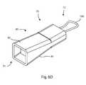
- the first fixation device 70may be an aperture plug system, and may extend from a leading end 72 to a trailing end 74 .
- the first fixation device 70may include an expanding element 80 , an expander 90 , and an actuation element 100 .
- the expanding element 80may be a sheath, a sleeve, a tube, or the like.
- the expander 90may be a wedge or the like.
- the actuation element 100may be used to urge the expander 90 into engagement with the expanding element 80 to cause expansion of the expanding element 80 .
- the actuation element 100may pull, push, twist, or otherwise urge the expander 90 into engagement with the expanding element 80 .
- the actuation element 100is a tension element such as a line, suture, cord, cable, wire, filament, or the like.
- the actuation element 100may also be a compression element, such as a shaft or pole, or a torque element, such as a hex key.
- the first fixation device 70may be implanted in a bone tunnel with the graft 10 resting against opposite sides 82 , 84 of the sleeve 80 .
- the suture 100may be pulled to draw the wedge 90 inside the sleeve 80 , thus expanding the sleeve as shown in FIG. 6D and urging the graft 10 against the bone tunnel.
- the trailing corners 92 of the wedge 90may dig into the sleeve 80 to prevent the wedge 90 from working itself out of the sleeve 80 .
- the wedge 90may also include other protrusions (not shown) which prevent backout.
- the sleeve 80may be smooth or textured.
- First fixation device 140may be another aperture plug which extends from a leading end 142 to a trailing end 144 .
- Aperture plug 140may be at least partially split so that the trailing end 144 bifurcates into two or more bendable legs 141 .
- the aperture plug 140may include opposing sets of protrusions 146 on outward facing lateral surfaces of the trailing end 144 .
- An aperture 148may extend through the leading end 142 and the two or more legs 141 may also be separated by an aperture 143 .
- Aperture plug 140may be at least partially formed from a flexible or resilient material so that the trailing end 144 can assume a more closed configuration as shown in FIG.
- First fixation device 140may be used with the loop 170 , button 30 , and graft in a manner similar to that described for first fixation device 20 .
- the loop 170may be threaded through the aperture 148 and the graft may rest against the protrusions 146 so that the trailing end 144 tends to urge the graft against the bone tunnel wall.
- Second fixation device 180may be described as an extracortical suspensory button.
- Button 180may be made of a flexible or resilient material that allows it to collapse to a smaller size and expand to a larger size.
- the button 180is shown as a coiled structure which may have a closely packed configuration, shown in FIG. 8B , and an at least partially uncoiled configuration, shown in FIG. 8A .
- the uncoiled configurationmay permit the button 180 to slide lengthwise through a bone tunnel, while the packed configuration may permit the button to rest on an extracortical bone surface to support the graft 10 with a connector 190 , as shown in FIG. 8C .
- the button 180may be made of a metal or fiber mesh which is woven and coiled to provide the described configurations and functions.
- Cortical fixation system 200can include a washer 230 and screw or screw construct (not shown).
- the washer 230may be described as an extracortical button and can have an aperture 232 configured to receive the screw.
- the screwcan be polyaxially pivotable with respect to the washer 230 .
- the system 200may be implanted in a proximal tibia so that the washer 230 may rest on an extracortical surface of the tibia and the screw may reside in a tibial bone tunnel which extends through an original tibial attachment area of the anterior cruciate ligament.
- the washer 230may include peripheral grooves or notches 234 to receive sutures (not shown) stitched to the ends of the graft.
- the suturescan be tied to the washer 230 by wrapping the sutures around the washer 230 in a variety of different patterns.
- the grooves or notches 234can help engage the sutures to the washer 230 .
- the washer 280can include an aperture 270 configured to receive a screw (not shown).
- the system 200may be implanted in a proximal tibia so that the washer 230 may rest on an extracortical surface of the tibia and the screw may reside in a tibial bone tunnel which extends through an original tibial attachment area of the anterior cruciate ligament.
- the washer 280may also include apertures 282 for receiving sutures (not shown) stitched to the ends of the graft.
- the suturescan be tied to the washer 230 by threading the sutures through the apertures 282 formed in the washer 280 in a variety of different patterns. In this manner, the apertures 282 can help engage the sutures to the washer 280 .
- the washer 320can include an aperture 321 configured to receive a screw (not shown).
- the washer 320may include broad peripheral grooves or notches 322 to receive the ends of the graft and/or sutures (not shown).
- the washer 320may have a FIG. 8 , bar, bowtie, or dogbone appearance.
- the sutures and/or graftcan be tied to the washer 320 by wrapping the sutures around the washer 320 in a variety of different patterns.
- the grooves or notches 322can help engage the sutures to the washer 320 .
- the fixation system 330may include a first fixation device 340 , a second fixation device (not shown), and a connector 350 .
- the first fixation device 340may be an aperture plug.
- the second fixation devicemay be an extracortical suspensory button or washer, as disclosed herein.
- the connector 350may include a threaded fastener 364 which may be a self-tapping screw.
- the plug 340may extend from a leading end 342 to a trailing end 344 .
- the plug 340may be at least partially split lengthwise so that the trailing end 344 bifurcates.
- the plug 340may include a portion which forms a chamber 346 to receive the fastener 360 .
- the plug 340may form an aperture or eyelet 348 near the leading end 342 .
- the second fixation devicemay include any of the features set forth for other washers in this disclosure.
- the washermay be polyaxially pivotable about a head of the connector 350 .
- the connector 350may include a taper or wedge 362 , which may be integral with or formed separately from the threaded fastener 364 .
- the tibial fixation system 330may be implanted so that the washer rests against an extracortical bone surface of the proximal tibia, the plug 340 is in a bone tunnel which extends through an original tibial attachment area of the anterior cruciate ligament, and the graft (not shown) rests against side surfaces 341 , 343 of the plug.
- the wedge 362forces the trailing end 344 to expand and force the graft against the bone tunnel.
- expansionmay be controlled in this system by limiting the threaded engagement with the chamber 346 and/or by providing a thread relief.
- expansionmay be limited when the wedge 362 makes contact with the chamber.
- the first fixation device 340may be fabricated from polymer, metal, ceramic, bone, or other biocompatible material.
- the first fixation device 340may include a solid polymer portion and a portion formed from bone.
- the polymer portionmay be polyetheretherketone (PEEK).
- PEEKpolyetheretherketone
- the solid polymer portionmay form at least part of the leading end 342 and the bone portion may form at least part of the trailing end 344 .
- the cortical fixation system 370may include an expanding element 380 , an expander 390 , and an actuation element 400 .
- the expanding element 380may be an aperture plug which is at least partially split lengthwise.
- the expander 390may be a wedge, cam, or the like.
- the actuation element 400may be used to urge the expander 390 into engagement with the expanding element 380 to cause expansion of the expanding element 380 .
- the actuation element 400may pull, push, twist, or otherwise urge the expander 390 into engagement with the expanding element 380 .
- the actuation element 400is a tension element such as a line, suture, cord, cable, wire, filament, or the like.
- the actuation element 400may also be a compression element, such as a shaft or pole, or a torque element, such as a hex key.
- the system 370may be implanted in a bone tunnel with the graft (not shown) resting against opposite sides 382 , 384 of the plug 380 .
- the suture 400may be pulled to draw the wedge 390 inside the plug 380 , thus expanding the plug as shown in FIG. 11B and urging the graft against the bone tunnel.
- the wedge 390may include protrusions (not shown) which prevent backout.
- the actuation element 400may hold the wedge 390 in place permanently.
- the plug 380may be smooth or textured.
- Washer 410forms a portion of a full circle or oval, and includes peripheral notches 412 around the circular portion. This may increase visibility and flexibility in surgical uses.
- Washer 420forms a full circle, and includes a large central aperture 421 which is spanned by a bar 424 . This may increase visibility of the graft and/or sutures.
- the bar 424can also have an aperture 422 formed therein and configured to receive a screw construct (not shown).
- Washer 430is circular or oval, and includes peripheral notches 432 . This may increase flexibility in surgical uses.
- Washers 410 , 420 , and 430may be used in place of other washers disclosed herein. Any of the washers disclosed herein may include features to permit adjustment and locking of a line, such as a suture, to the washer, such as nothches or grooves.
- the washerscan have one or more narrowing slits around the periphery of the washer. The narrowing slits can be open wider toward the outer periphery of the washer and narrow toward the inner portion of the washer. In this manner, the suture can be easily guided into the narrowing slit.
- the narrowing slitscan also have a final width toward the inner portion of the washer that is less than or equal to the width of the suture, such that the suture becomes “wedged” or trapped in the narrowing slit and held in place by the narrowing slit.
- Any of the washers disclosed hereincan have one or more narrowing slits around the periphery of the washer in place of, or in addition to the other features disclosed herein.
- the tamp 520can be cannulated and configured to receive a guide wire (not shown) to guide the tamp 520 to the bone tunnel.
- the guide wirecan be fed through aperture or cannulation 528 .
- the tamp 520may include a handle 522 , a shaft 524 , and a body 526 .
- the handle 522may include a striking platform.
- additional cannulations 527 , 529are included.
- the body 526may have a cross-sectional shape that is oblong, bowtie shaped, figure eight shaped, dumbbell shaped, bicuspid epicycloid shaped, or Gerono lemniscate shaped.
- a cross-sectional area of the body 526 , transverse to the longitudinal axis of the shaft 524can have a plurality of lobes (not shown) having a height and a width, wherein the height of the lobes is greater than the width of the lobes.
- the cross-sectional area of the body 526 transverse to the longitudinal axiscan have a figure eight shape (not shown) with two lobes overlapping each other forming a pair of indentations (not shown).
- the pair of indentationscan have at least one concave portion and at least one convex portion.
- the body 526can also include cutting surfaces (not shown) which protrude from the sides of the body 526 and configured to remove pieces of bone as the body 526 is advanced into the bone tunnel.
- the body 526can also have at least one recessed area (not shown) adjacent to the at least one cutting surface and configured to capture the removed portions of bone as the tool is advanced into the bone tunnel.
- the body 526can also have at least one aperture configured to facilitate removal of trapped bone portions.
- the guide wiremay be positioned in the bone relative to the bone tunnel.
- the guide wiremay be received in cannulation 528 so that the body 526 slides into the bone tunnel along the guide wire.
- the tamp 520may be pushed or impacted into the tunnel to refine the size and/or shape of the tunnel to receive an implant.
- the guide wiremay be received in one of the additional cannulations 527 , 529 to offset the tamp 520 relative to the bone tunnel.
- the tamp 520may asymmetrically refine the size and/or shape of the tunnel.
- the tamp 550may share some or all of the characteristics of the tamp 520 .
- the tamp 550may include a handle or impact member 551 , a shaft 554 and a body 556 .
- the handle 522may include a striking platform.
- the body 556may have a cross-sectional shape that is oblong, bowtie shaped, figure eight shaped, dumbbell shaped, bicuspid epicycloid shaped, or Gerono lemniscate shaped.
- the tamp 550can be cannulated 552 and configured to receive a guide wire (not shown) to guide the tamp 550 to the bone tunnel.
- a leading portion 558 of the body 556may be reduced in size and/or may be shaped to fit an unmodified bone tunnel.
- the leading portion 558may also be described as a guide tip. In use, the leading portion 558 may be easily introduced into the bone tunnel.
- the tamp 550may then be pushed or impacted to drive it further into the tunnel.
- the leading portion 558may follow the bone tunnel to guide the tamp 550 along the tunnel.
- the preceding disclosurecontemplates a single bone tunnel with a non-circular cross section. More specifically, the preceding disclosure contemplates a tunnel whose cross section is shaped like an oblong, a bowtie, a figure eight, a dumbbell, a bicuspid epicycloid, or a Gerono lemniscate, or another shape which has a length greater than its width and a narrowing or constricted midportion across its width.
- Other bone tunnelsare also contemplated. For example, two separate bone tunnels are contemplated.
- the bone tunnelscan be formed in the tibia, for example.
- the tunnelsmay be parallel, intersecting, or skewed. Parallel or skewed tunnels may be separated by a bone bridge. Separate tibial tunnels may facilitate independent tensioning of the AM and PL graft bundles at relevant knee flexion angles.
- the drill guide 560may include an arm 570 , a first rail 580 , a second rail 590 , a first guide tube 600 , and a second guide tube 610 .
- the arm 570may include a working portion 572 , which may include a first loop 574 which is pierced by an aperture 575 .
- the working portion 572may also include a second loop 576 pierced by a second aperture 577 , adjacent to the first loop 574 .
- the working portion 572may be pressed against the tibial ACL attachment area so that the first loop 574 is centered in the antero-medial bundle attachment area and the second loop 576 is generally centered in the postero-lateral bundle attachment area. Alternatively, the entire working portion 572 may be generally aligned with and centered in the total tibial ACL attachment area.
- the working portion 572may include a grip member, such as a spike or tooth (not shown) to dig into the tibial plateau.
- the first rail 580may be arcuate.
- the first guide tube 600may be carried on the first rail 580 so that a center longitudinal axis 602 of the guide tube always passes through a center point of the aperture 575 , regardless of the position of the first guide tube along the first rail.
- the second rail 590may also be arcuate.
- the second guide tube 610may be carried on the second rail 590 so that a center longitudinal axis 612 of the guide tube always passes through a center point of the aperture 577 , regardless of the position of the second guide tube along the second rail.
- the second rail 590may be held at an angle with respect to the first rail 580 .
- the anglemay be fixed or variable.
- the first and second rails 580 , 590may be formed as a single part or rigidly fixed together.
- the first and second rails 580 , 590may be hinged together near the arm 570 .
- the second guide tube 610may be held at an angle with respect to the first guide tube 600 .
- the anglemay be fixed or variable.
- first and second guide tubes 600 , 610may move together along the rails 580 , 590 in a fixed relationship.
- the first and second guide tubes 600 , 610may each be independently movable along the rails 580 , 590 .
- the tibial drill guide 560may include means to ensure that the axis 602 always passes through the center of the aperture 575 and the axis 612 always passes through the center of the aperture 577 , regardless of the magnitude of the angle.
- fixation devices disclosed hereinmay be adapted for use in the femur, the tibia, or in other suspensory fixation applications, as mentioned previously.
- any of the devices described hereinmay be fabricated from metals, alloys, polymers, plastics, ceramics, glasses, composite materials, or combinations thereof. Different materials may be used within a single part.
- Coupledis defined as connected, although not necessarily directly, and not necessarily mechanically.
- a step of a method or an element of a devicethat “comprises,” “has,” “includes” or “contains” one or more features, possesses those one or more features, but is not limited to possessing only those one or more features.
- a device or structure that is configured in a certain wayis configured in at least that way, but may also be configured in ways that are not listed.
Landscapes
- Health & Medical Sciences (AREA)
- Life Sciences & Earth Sciences (AREA)
- Orthopedic Medicine & Surgery (AREA)
- Veterinary Medicine (AREA)
- Animal Behavior & Ethology (AREA)
- Oral & Maxillofacial Surgery (AREA)
- Public Health (AREA)
- Engineering & Computer Science (AREA)
- Biomedical Technology (AREA)
- Heart & Thoracic Surgery (AREA)
- General Health & Medical Sciences (AREA)
- Rheumatology (AREA)
- Cardiology (AREA)
- Vascular Medicine (AREA)
- Transplantation (AREA)
- Rehabilitation Therapy (AREA)
- Surgery (AREA)
- Dentistry (AREA)
- Nuclear Medicine, Radiotherapy & Molecular Imaging (AREA)
- Medical Informatics (AREA)
- Molecular Biology (AREA)
- Prostheses (AREA)
- Surgical Instruments (AREA)
Abstract
Description
Claims (25)
Priority Applications (2)
| Application Number | Priority Date | Filing Date | Title |
|---|---|---|---|
| US13/655,186US8968402B2 (en) | 2011-10-18 | 2012-10-18 | ACL implants, instruments, and methods |
| US14/608,561US20150142110A1 (en) | 2011-10-18 | 2015-01-29 | Acl implants, instruments, and methods |
Applications Claiming Priority (2)
| Application Number | Priority Date | Filing Date | Title |
|---|---|---|---|
| US201161548467P | 2011-10-18 | 2011-10-18 | |
| US13/655,186US8968402B2 (en) | 2011-10-18 | 2012-10-18 | ACL implants, instruments, and methods |
Related Child Applications (1)
| Application Number | Title | Priority Date | Filing Date |
|---|---|---|---|
| US14/608,561DivisionUS20150142110A1 (en) | 2011-10-18 | 2015-01-29 | Acl implants, instruments, and methods |
Publications (2)
| Publication Number | Publication Date |
|---|---|
| US20130096677A1 US20130096677A1 (en) | 2013-04-18 |
| US8968402B2true US8968402B2 (en) | 2015-03-03 |
Family
ID=48086514
Family Applications (2)
| Application Number | Title | Priority Date | Filing Date |
|---|---|---|---|
| US13/655,186Active2033-01-12US8968402B2 (en) | 2011-10-18 | 2012-10-18 | ACL implants, instruments, and methods |
| US14/608,561AbandonedUS20150142110A1 (en) | 2011-10-18 | 2015-01-29 | Acl implants, instruments, and methods |
Family Applications After (1)
| Application Number | Title | Priority Date | Filing Date |
|---|---|---|---|
| US14/608,561AbandonedUS20150142110A1 (en) | 2011-10-18 | 2015-01-29 | Acl implants, instruments, and methods |
Country Status (1)
| Country | Link |
|---|---|
| US (2) | US8968402B2 (en) |
Cited By (37)
| Publication number | Priority date | Publication date | Assignee | Title |
|---|---|---|---|---|
| US10016220B2 (en) | 2011-11-01 | 2018-07-10 | Nuvasive Specialized Orthopedics, Inc. | Adjustable magnetic devices and methods of using same |
| US10039661B2 (en) | 2006-10-20 | 2018-08-07 | Nuvasive Specialized Orthopedics, Inc. | Adjustable implant and method of use |
| US10238427B2 (en) | 2015-02-19 | 2019-03-26 | Nuvasive Specialized Orthopedics, Inc. | Systems and methods for vertebral adjustment |
| US10271885B2 (en) | 2014-12-26 | 2019-04-30 | Nuvasive Specialized Orthopedics, Inc. | Systems and methods for distraction |
| US10349995B2 (en) | 2007-10-30 | 2019-07-16 | Nuvasive Specialized Orthopedics, Inc. | Skeletal manipulation method |
| US10405891B2 (en) | 2010-08-09 | 2019-09-10 | Nuvasive Specialized Orthopedics, Inc. | Maintenance feature in magnetic implant |
| US10478232B2 (en) | 2009-04-29 | 2019-11-19 | Nuvasive Specialized Orthopedics, Inc. | Interspinous process device and method |
| US10517643B2 (en) | 2009-02-23 | 2019-12-31 | Nuvasive Specialized Orthopedics, Inc. | Non-invasive adjustable distraction system |
| US10617453B2 (en) | 2015-10-16 | 2020-04-14 | Nuvasive Specialized Orthopedics, Inc. | Adjustable devices for treating arthritis of the knee |
| US10646262B2 (en) | 2011-02-14 | 2020-05-12 | Nuvasive Specialized Orthopedics, Inc. | System and method for altering rotational alignment of bone sections |
| US10660675B2 (en) | 2010-06-30 | 2020-05-26 | Nuvasive Specialized Orthopedics, Inc. | External adjustment device for distraction device |
| US10729470B2 (en) | 2008-11-10 | 2020-08-04 | Nuvasive Specialized Orthopedics, Inc. | External adjustment device for distraction device |
| US10743794B2 (en) | 2011-10-04 | 2020-08-18 | Nuvasive Specialized Orthopedics, Inc. | Devices and methods for non-invasive implant length sensing |
| US10751094B2 (en) | 2013-10-10 | 2020-08-25 | Nuvasive Specialized Orthopedics, Inc. | Adjustable spinal implant |
| US10828146B2 (en) | 2016-08-04 | 2020-11-10 | Stryker Corporation | Instrumentation for soft tissue reconstruction |
| US10835290B2 (en) | 2015-12-10 | 2020-11-17 | Nuvasive Specialized Orthopedics, Inc. | External adjustment device for distraction device |
| US10918425B2 (en) | 2016-01-28 | 2021-02-16 | Nuvasive Specialized Orthopedics, Inc. | System and methods for bone transport |
| US11191579B2 (en) | 2012-10-29 | 2021-12-07 | Nuvasive Specialized Orthopedics, Inc. | Adjustable devices for treating arthritis of the knee |
| US11202707B2 (en) | 2008-03-25 | 2021-12-21 | Nuvasive Specialized Orthopedics, Inc. | Adjustable implant system |
| US11207110B2 (en) | 2009-09-04 | 2021-12-28 | Nuvasive Specialized Orthopedics, Inc. | Bone growth device and method |
| US11246694B2 (en) | 2014-04-28 | 2022-02-15 | Nuvasive Specialized Orthopedics, Inc. | System for informational magnetic feedback in adjustable implants |
| USRE49061E1 (en) | 2012-10-18 | 2022-05-10 | Nuvasive Specialized Orthopedics, Inc. | Intramedullary implants for replacing lost bone |
| US11357547B2 (en) | 2014-10-23 | 2022-06-14 | Nuvasive Specialized Orthopedics Inc. | Remotely adjustable interactive bone reshaping implant |
| US11357549B2 (en) | 2004-07-02 | 2022-06-14 | Nuvasive Specialized Orthopedics, Inc. | Expandable rod system to treat scoliosis and method of using the same |
| US11577097B2 (en) | 2019-02-07 | 2023-02-14 | Nuvasive Specialized Orthopedics, Inc. | Ultrasonic communication in medical devices |
| US11589901B2 (en) | 2019-02-08 | 2023-02-28 | Nuvasive Specialized Orthopedics, Inc. | External adjustment device |
| US11696836B2 (en) | 2013-08-09 | 2023-07-11 | Nuvasive, Inc. | Lordotic expandable interbody implant |
| US11737787B1 (en) | 2021-05-27 | 2023-08-29 | Nuvasive, Inc. | Bone elongating devices and methods of use |
| US11766252B2 (en) | 2013-07-31 | 2023-09-26 | Nuvasive Specialized Orthopedics, Inc. | Noninvasively adjustable suture anchors |
| US11801187B2 (en) | 2016-02-10 | 2023-10-31 | Nuvasive Specialized Orthopedics, Inc. | Systems and methods for controlling multiple surgical variables |
| US11806054B2 (en) | 2021-02-23 | 2023-11-07 | Nuvasive Specialized Orthopedics, Inc. | Adjustable implant, system and methods |
| US11839410B2 (en) | 2012-06-15 | 2023-12-12 | Nuvasive Inc. | Magnetic implants with improved anatomical compatibility |
| US11857226B2 (en) | 2013-03-08 | 2024-01-02 | Nuvasive Specialized Orthopedics | Systems and methods for ultrasonic detection of device distraction |
| US11925389B2 (en) | 2008-10-13 | 2024-03-12 | Nuvasive Specialized Orthopedics, Inc. | Spinal distraction system |
| US12023073B2 (en) | 2021-08-03 | 2024-07-02 | Nuvasive Specialized Orthopedics, Inc. | Adjustable implant |
| US12213708B2 (en) | 2020-09-08 | 2025-02-04 | Nuvasive Specialized Orthopedics, Inc. | Remote control module for adjustable implants |
| US20250107793A1 (en)* | 2023-09-28 | 2025-04-03 | Arthrex, Inc. | Surgical locking buttons |
Families Citing this family (21)
| Publication number | Priority date | Publication date | Assignee | Title |
|---|---|---|---|---|
| US8932355B2 (en) | 2008-02-22 | 2015-01-13 | Coalign Innovations, Inc. | Spinal implant with expandable fixation |
| US8992620B2 (en) | 2008-12-10 | 2015-03-31 | Coalign Innovations, Inc. | Adjustable distraction cage with linked locking mechanisms |
| US8696751B2 (en)* | 2008-12-10 | 2014-04-15 | Coalign Innovations, Inc. | Adjustable distraction cage with linked locking mechanisms |
| US12232975B2 (en) | 2008-02-22 | 2025-02-25 | Howmedica Osteonics Corp. | Lockable spinal implant |
| US20100145455A1 (en) | 2008-12-10 | 2010-06-10 | Innvotec Surgical, Inc. | Lockable spinal implant |
| US20100121375A1 (en)* | 2008-11-13 | 2010-05-13 | Pandya Rajiv D | Suture anchoring system and method |
| CN102481187B (en)* | 2009-03-31 | 2016-06-08 | 医学嵌入公司暨Imds共同创新公司 | Double bundle acl is repaired |
| US8968402B2 (en) | 2011-10-18 | 2015-03-03 | Arthrocare Corporation | ACL implants, instruments, and methods |
| FR2995401B1 (en)* | 2012-09-12 | 2014-09-12 | Snecma | MEASURING ROD OF EPICYCLOID SECTION |
| USD730267S1 (en)* | 2014-03-19 | 2015-05-26 | Jeremy Janeczko | Portable bike carrier |
| DE102015007541A1 (en)* | 2015-06-16 | 2016-12-22 | Adalbert Missalla | Tool for dilation of bone holes in reconstructive surgery and tool kit comprising such a tool |
| US9925010B2 (en) | 2016-02-19 | 2018-03-27 | Rajiv D. Pandya | System and technique for accessing extra articular lesions or abnormalities or intra osseous lesions or bone marrow lesions |
| US11376079B2 (en) | 2016-02-19 | 2022-07-05 | Rajiv D. Pandya | System and technique for accessing extra articular lesions or abnormalities or intra osseous lesions or bone marrow lesions |
| US11419684B2 (en) | 2016-02-19 | 2022-08-23 | Rajiv D. Pandya | System and technique for accessing extra articular lesions or abnormalities or intra osseous lesions or bone marrow lesions |
| US10064632B2 (en) | 2016-02-19 | 2018-09-04 | Rajiv D. Pandya | System and technique for accessing extra articular lesions or abnormalities or intra osseous lesions or bone marrow lesions |
| US10548738B2 (en) | 2016-04-07 | 2020-02-04 | Howmedica Osteonics Corp. | Expandable interbody implant |
| AU2017203369B2 (en) | 2016-05-20 | 2022-04-28 | Vb Spine Us Opco Llc | Expandable interbody implant with lordosis correction |
| AU2017228529B2 (en) | 2016-09-12 | 2022-03-10 | Vb Spine Us Opco Llc | Interbody implant with independent control of expansion at multiple locations |
| AU2017251734B2 (en) | 2016-10-26 | 2022-10-20 | Vb Spine Us Opco Llc | Expandable interbody implant with lateral articulation |
| US11883243B2 (en) | 2019-10-31 | 2024-01-30 | Orthopediatrics Corp. | Assessment of tension between bone anchors |
| US11963688B2 (en) | 2021-11-20 | 2024-04-23 | Panorthopaedics, Inc. | Device adapted for lateral engagement of an elongated member |
Citations (201)
| Publication number | Priority date | Publication date | Assignee | Title |
|---|---|---|---|---|
| US3176316A (en) | 1963-01-07 | 1965-04-06 | Bruce R Bodell | Plastic prosthetic tendon |
| US3832931A (en) | 1971-12-21 | 1974-09-03 | M Talan | Device for fastening objects to walls or other supports |
| US4187558A (en) | 1977-10-25 | 1980-02-12 | Cutter Laboratories, Inc. | Prosthetic ligament |
| US4411027A (en) | 1979-04-27 | 1983-10-25 | University Of Medicine And Dentistry Of New Jersey | Bio-absorbable composite tissue scaffold |
| US4662886A (en) | 1984-06-04 | 1987-05-05 | A. W. Showell (Surgicraft) Limited | Surgical element |
| US4738255A (en) | 1986-04-07 | 1988-04-19 | Biotron Labs, Inc. | Suture anchor system |
| US4772286A (en) | 1987-02-17 | 1988-09-20 | E. Marlowe Goble | Ligament attachment method and apparatus |
| US4773910A (en) | 1987-08-17 | 1988-09-27 | Johnson & Johnson Consumer Products, Inc. | Permanent ligament prosthesis |
| US4792336A (en) | 1986-03-03 | 1988-12-20 | American Cyanamid Company | Flat braided ligament or tendon implant device having texturized yarns |
| US4932972A (en) | 1986-03-14 | 1990-06-12 | Richards Medical Company | Prosthetic ligament |
| US5004474A (en) | 1989-11-28 | 1991-04-02 | Baxter International Inc. | Prosthetic anterior cruciate ligament design |
| US5037422A (en) | 1990-07-02 | 1991-08-06 | Acufex Microsurgical, Inc. | Bone anchor and method of anchoring a suture to a bone |
| US5100417A (en) | 1990-07-13 | 1992-03-31 | American Cyanamid Company | Suture anchor and driver assembly |
| US5112335A (en) | 1989-07-11 | 1992-05-12 | Laboureau Jacques Philippe | Instrument for marking and drilling femoral and tibial insertion tunnels |
| US5171259A (en) | 1990-04-02 | 1992-12-15 | Kanji Inoue | Device for nonoperatively occluding a defect |
| US5176682A (en) | 1992-06-01 | 1993-01-05 | Chow James C Y | Surgical implement |
| US5207753A (en) | 1991-02-18 | 1993-05-04 | Kannivelu Badrinath | Bone fracture repair apparatus and method |
| US5234430A (en) | 1991-12-18 | 1993-08-10 | Huebner Randall J | Orthopedic fixation screw and method |
| US5236445A (en) | 1990-07-02 | 1993-08-17 | American Cyanamid Company | Expandable bone anchor and method of anchoring a suture to a bone |
| US5258016A (en) | 1990-07-13 | 1993-11-02 | American Cyanamid Company | Suture anchor and driver assembly |
| US5268001A (en) | 1990-09-25 | 1993-12-07 | Innovasive Devices, Inc. | Bone fastener |
| US5306301A (en) | 1993-02-11 | 1994-04-26 | American Cyanamid Company | Graft attachment device and method of using same |
| US5370662A (en) | 1993-06-23 | 1994-12-06 | Kevin R. Stone | Suture anchor assembly |
| US5376101A (en) | 1992-10-09 | 1994-12-27 | The United States Surgical Corporation | Suture retaining clip |
| US5383905A (en) | 1992-10-09 | 1995-01-24 | United States Surgical Corporation | Suture loop locking device |
| US5393302A (en) | 1992-10-05 | 1995-02-28 | Clark; Ron | Process for endosteal ligament mounting |
| USRE34871E (en) | 1989-05-15 | 1995-03-07 | Mcguire; David A. | Process of endosteal fixation of a ligament |
| US5423819A (en) | 1989-02-06 | 1995-06-13 | American Cyanamid Company | Screw and driver for securing a bone block |
| US5425766A (en) | 1987-03-09 | 1995-06-20 | Astra Tech Aktiebolag | Resorbable prosthesis |
| CA2181179A1 (en) | 1994-01-13 | 1995-07-20 | David A. Mcguire | Bone-cutting guide |
| US5458601A (en) | 1994-03-28 | 1995-10-17 | Medical University Of South Carolina | Adjustable ligament anchor |
| US5464427A (en) | 1994-10-04 | 1995-11-07 | Synthes (U.S.A.) | Expanding suture anchor |
| US5505735A (en) | 1993-06-10 | 1996-04-09 | Mitek Surgical Products, Inc. | Surgical anchor and method for using the same |
| US5520693A (en) | 1992-02-19 | 1996-05-28 | Mcguire; David A. | Femoral guide and methods of precisely forming bone tunnels in cruciate ligament reconstruction of the knee |
| US5545180A (en) | 1993-12-13 | 1996-08-13 | Ethicon, Inc. | Umbrella-shaped suture anchor device with actuating ring member |
| US5562669A (en) | 1994-01-13 | 1996-10-08 | Mcguire; David A. | Cruciate ligament reconstruction with tibial drill guide |
| US5571184A (en) | 1995-06-07 | 1996-11-05 | Wright Medical Technology, Inc. | Graft fixation device and method of using |
| US5575819A (en) | 1986-09-19 | 1996-11-19 | Imperial College Of Science And Technology | Artificial ligaments |
| US5584835A (en) | 1993-10-18 | 1996-12-17 | Greenfield; Jon B. | Soft tissue to bone fixation device and method |
| US5601557A (en) | 1982-05-20 | 1997-02-11 | Hayhurst; John O. | Anchoring and manipulating tissue |
| US5632748A (en) | 1993-06-14 | 1997-05-27 | Linvatec Corporation | Endosteal anchoring device for urging a ligament against a bone surface |
| US5681320A (en) | 1991-12-13 | 1997-10-28 | Mcguire; David A. | Bone-cutting guide |
| US5707395A (en) | 1997-01-16 | 1998-01-13 | Li Medical Technologies, Inc. | Surgical fastener and method and apparatus for ligament repair |
| US5709683A (en) | 1995-12-19 | 1998-01-20 | Spine-Tech, Inc. | Interbody bone implant having conjoining stabilization features for bony fusion |
| US5733307A (en) | 1996-09-17 | 1998-03-31 | Amei Technologies, Inc. | Bone anchor having a suture trough |
| US5827285A (en) | 1996-12-12 | 1998-10-27 | Bramlet; Dale G. | Multipiece interfragmentary fixation assembly |
| US5871504A (en) | 1997-10-21 | 1999-02-16 | Eaton; Katulle Koco | Anchor assembly and method for securing ligaments to bone |
| US5899938A (en) | 1996-11-27 | 1999-05-04 | Joseph H. Sklar | Graft ligament anchor and method for attaching a graft ligament to a bone |
| US5918604A (en) | 1997-02-12 | 1999-07-06 | Arthrex, Inc. | Method of loading tendons into the knee |
| US5935129A (en) | 1997-03-07 | 1999-08-10 | Innovasive Devices, Inc. | Methods and apparatus for anchoring objects to bone |
| US5957953A (en) | 1996-02-16 | 1999-09-28 | Smith & Nephew, Inc. | Expandable suture anchor |
| US5984966A (en) | 1998-03-02 | 1999-11-16 | Bionx Implants Oy | Bioabsorbable bone block fixation implant |
| US5997539A (en) | 1997-05-15 | 1999-12-07 | Spinal Concepts, Inc. | Polyaxial pedicle screw having a compression locking rod gripping mechanism |
| US6001100A (en) | 1997-08-19 | 1999-12-14 | Bionx Implants Oy | Bone block fixation implant |
| US6001106A (en) | 1997-09-03 | 1999-12-14 | M & R Medical, Inc. | System for tensioning ligament grafts |
| US6022373A (en) | 1996-09-10 | 2000-02-08 | Li Medical Technologies, Inc. | Surgical anchor and package and cartridge for surgical anchor |
| US6022356A (en) | 1998-03-18 | 2000-02-08 | Smith & Nephew, Inc. | Cruciate ligament reconstruction template |
| US6056752A (en) | 1997-10-24 | 2000-05-02 | Smith & Nephew, Inc. | Fixation of cruciate ligament grafts |
| US6099568A (en) | 1998-03-03 | 2000-08-08 | Linvatec Corporation | ACL graft fixation device and method |
| US6099530A (en) | 1998-04-09 | 2000-08-08 | Smith & Nephew, Inc. | Soft-tissue intra-tunnel fixation device |
| US6110207A (en) | 1996-04-23 | 2000-08-29 | Aesculap Ag & Co. Kg | Implant for securing a tendon replacement member |
| US6129762A (en) | 1994-08-22 | 2000-10-10 | Li Medical Technologies, Inc. | Anchor and method for securement into a bore |
| US6193754B1 (en) | 1996-09-26 | 2001-02-27 | Neoligaments Limited | Attachment device for use in the implantation of prosthetic ligament |
| US6221107B1 (en) | 1998-08-03 | 2001-04-24 | Mark E. Steiner | Ligament fixation device and method |
| US6235057B1 (en) | 1995-01-24 | 2001-05-22 | Smith & Nephew, Inc. | Method for soft tissue reconstruction |
| US6264694B1 (en) | 1999-02-11 | 2001-07-24 | Linvatec Corporation | Soft tissue graft fixation device and method |
| US6283996B1 (en) | 1996-09-20 | 2001-09-04 | Medicine, Lodge, Inc. | Adjustable length strap and footing for ligament mounting and method for its use |
| US6290711B1 (en) | 1999-08-13 | 2001-09-18 | Innovasive Devices, Inc. | Connector device and method for surgically joining and securing flexible tissue repair members |
| US20020007182A1 (en) | 1998-08-19 | 2002-01-17 | Kim Andrew C. | Anterior cruciate ligament reconstruction hamstring tendon fixation system |
| US6440134B1 (en) | 1999-07-29 | 2002-08-27 | Giovanni Zaccherotti | Device for the femoral fixation of the semitendinosus and gracilis tendons for the reconstruction of the anterior cruciate ligament of the knee |
| US20020161439A1 (en) | 1999-09-01 | 2002-10-31 | Michael Strobel | Instrumentarium for implanting a tendon replacement |
| US20020165611A1 (en) | 1998-12-22 | 2002-11-07 | Robert-Jan Enzerink | Graft material convenience package |
| US6497726B1 (en) | 2000-01-11 | 2002-12-24 | Regeneration Technologies, Inc. | Materials and methods for improved bone tendon bone transplantation |
| US6508830B2 (en) | 2001-04-30 | 2003-01-21 | Musculoskeletal Transplant Foundation | Suture anchor |
| US6517578B2 (en) | 1999-12-15 | 2003-02-11 | Atlantech Medical Devices Limited | Graft suspension device |
| US6517579B1 (en) | 2000-09-06 | 2003-02-11 | Lonnie E. Paulos | Method and apparatus for securing a soft tissue graft to bone during an ACL reconstruction |
| US6517542B1 (en) | 1999-08-04 | 2003-02-11 | The Cleveland Clinic Foundation | Bone anchoring system |
| US6533802B2 (en) | 2001-05-16 | 2003-03-18 | Smith & Nephew, Inc. | Endobutton continuous loop for bone-tendon-bone |
| US20030065390A1 (en) | 2001-09-28 | 2003-04-03 | Justin Daniel F. | Expanding ligament graft fixation system and method |
| US6547564B1 (en) | 1998-07-17 | 2003-04-15 | Astra Aktiebolag | Bone implant having circumferentially oriented roughness |
| US6554862B2 (en) | 1996-11-27 | 2003-04-29 | Ethicon, Inc. | Graft ligament anchor and method for attaching a graft ligament to a bone |
| US6562043B1 (en) | 1998-05-21 | 2003-05-13 | Kwan-Ho Chan | Apparatus and method for ligament fixation |
| US6579295B1 (en) | 2000-09-25 | 2003-06-17 | Robert S. Supinski | Tendon anchors |
| US20030130735A1 (en) | 2002-01-09 | 2003-07-10 | Roger Rogalski | Graft device and methods of use |
| US6599289B1 (en) | 2000-03-10 | 2003-07-29 | Smith & Nephew, Inc. | Graft anchor |
| US6616694B1 (en) | 1996-11-21 | 2003-09-09 | Ethicon, Inc. | Apparatus for anchoring autologous or artificial tendon grafts in bone |
| US20030171811A1 (en) | 2002-03-08 | 2003-09-11 | Steiner Anton J. | Bone-tendon-bone assembly with allograft bone block and method for inserting same |
| US20030171810A1 (en) | 2002-03-08 | 2003-09-11 | Steiner Anton J. | Bone-tendon-bone assembly with cancellous allograft bone block |
| US6623524B2 (en) | 2000-06-09 | 2003-09-23 | Arthrex, Inc. | Method for anterior cruciate ligament reconstruction using cross-pin implant with eyelet |
| US6629977B1 (en) | 1999-11-15 | 2003-10-07 | Arthrex, Inc. | Tapered bioabsorbable interference screw and method for endosteal fixation of ligaments |
| US20030191530A1 (en) | 1999-02-09 | 2003-10-09 | Sklar Joseph H. | Graft ligament anchor and method for attaching a graft ligament to a bone |
| US20030216780A1 (en) | 2002-05-15 | 2003-11-20 | Fitts Steven E. | Two piece cross-pin graft fixation |
| US6652560B1 (en) | 1999-07-03 | 2003-11-25 | Arthrocare Corporation | Bone anchor |
| US6652563B2 (en) | 2001-10-02 | 2003-11-25 | Arthrex, Inc. | Suture anchor with internal suture loop |
| US6656183B2 (en) | 2001-11-08 | 2003-12-02 | Smith & Nephew, Inc. | Tissue repair system |
| US20030233095A1 (en) | 2002-06-12 | 2003-12-18 | Urbanski Mark G. | Device and method for attaching soft tissue to bone |
| US6679890B2 (en) | 2001-08-28 | 2004-01-20 | Joseph Y. Margulies | Method and apparatus for augmentation of the femoral neck |
| US20040024456A1 (en) | 2000-03-16 | 2004-02-05 | Brown Charles H. | Sheaths for implantable fixation devices |
| US6712849B2 (en) | 2001-10-01 | 2004-03-30 | Scandius Biomedical, Inc. | Apparatus and method for reconstructing a ligament |
| US6716234B2 (en) | 2001-09-13 | 2004-04-06 | Arthrex, Inc. | High strength suture material |
| US6723099B1 (en) | 2001-11-08 | 2004-04-20 | Biomet, Inc. | Three sided tack for bone fixation |
| US20040153153A1 (en) | 2001-05-31 | 2004-08-05 | Elson Robert J. | Anterior cruciate ligament reconstruction system and method of implementing same |
| US20040199166A1 (en) | 2003-03-18 | 2004-10-07 | Reinhold Schmieding | ACL reconstruction technique using retrodrill |
| US6818010B2 (en) | 2000-04-29 | 2004-11-16 | Aesculap Ag & Co. Kg | Suture anchor system for joining pieces of tissue and instrument for inserting an anchor implant |
| US20040243132A1 (en) | 2003-05-27 | 2004-12-02 | Ethicon, Inc. | Tissue fixation device |
| US20040267318A1 (en) | 1997-07-23 | 2004-12-30 | Boucher James A | Apparatus and method for tibial fixation of soft tissue |
| US20040267361A1 (en) | 2003-06-27 | 2004-12-30 | Donnelly Lisa M. | Flexible tibial sheath |
| US20050010289A1 (en) | 1998-01-28 | 2005-01-13 | Mckernan Daniel J. | Method and apparatus for fixing a graft in a bone tunnel |
| US6863671B1 (en) | 1999-10-21 | 2005-03-08 | Storz Gmbh & Co. Kg | Biodegradable fixation element |
| US20050071004A1 (en) | 2001-10-01 | 2005-03-31 | Paul Re | Apparatus and method for reconstructing a ligament |
| US20050075668A1 (en) | 2000-10-18 | 2005-04-07 | Lizardi Jose E. | Knotless bioabsorbable suture anchor system and method |
| US6878166B2 (en) | 2000-08-28 | 2005-04-12 | Ron Clark | Method and implant for securing ligament replacement into the knee |
| US20050096743A1 (en) | 2003-10-30 | 2005-05-05 | Reinhold Schmieding | Method for creating a double bundle ligament orientation in a single bone tunnel during knee ligament reconstruction |
| US6893462B2 (en) | 2000-01-11 | 2005-05-17 | Regeneration Technologies, Inc. | Soft and calcified tissue implants |
| US6902578B1 (en) | 1999-01-05 | 2005-06-07 | Lifenet | Composite bone graft, method of making and using same |
| US20050159812A1 (en) | 2004-01-16 | 2005-07-21 | Dinger Fred B.Iii | Bone-tendon-bone implant |
| US6923810B1 (en) | 1988-06-13 | 2005-08-02 | Gary Karlin Michelson | Frusto-conical interbody spinal fusion implants |
| US6942666B2 (en) | 2002-03-29 | 2005-09-13 | Ethicon, Inc. | Expandable cable anchor |
| US20060030940A1 (en) | 2004-07-20 | 2006-02-09 | Reinhold Schmieding | Use of autogenous growth factors in bone tunnels during ligament reconstruction with mechanical containment implants |
| US7001390B2 (en) | 2002-02-08 | 2006-02-21 | Karl Storz Gmbh & Co. Kg | Anchoring element for anchoring a ligament transplant |
| US20060052787A1 (en) | 2004-08-18 | 2006-03-09 | Paul Re | Method and apparatus for reconstructing a ligament |
| US7025786B2 (en) | 1999-07-20 | 2006-04-11 | Ethicon, Inc. | Apparatus and method for reconstructing a ligament |
| US20060095130A1 (en) | 2004-10-29 | 2006-05-04 | Arthrex, Inc. | Ligament fixation using graft harness |
| US20060142769A1 (en) | 2002-11-21 | 2006-06-29 | Michel Collette | Anchoring screw for a relay strip or suture |
| US20060155290A1 (en) | 2003-07-11 | 2006-07-13 | Konsei Shino | Instrument for reconstructing ligament and method of reconstructing ligament |
| US20060155287A1 (en) | 2004-11-18 | 2006-07-13 | Montgomery Kenneth D | Devices, systems and methods for material fixation |
| US20060247642A1 (en) | 2004-11-09 | 2006-11-02 | Stone Kevin T | Tissue fixation device |
| US20060247790A1 (en) | 2005-04-30 | 2006-11-02 | Mckay William F | Shaped osteochondral grafts and methods of using same |
| US7144424B2 (en) | 2002-04-12 | 2006-12-05 | Karl Storz Gmbh & Co. Kg | Method and apparatus for reconstructing a ligament |
| US7189251B2 (en) | 1995-08-22 | 2007-03-13 | Orthohelix Surgical Designs, Inc. | Open helical organic tissue anchor having recessible head and method of making the organic tissue anchor |
| US7211088B2 (en) | 1999-02-02 | 2007-05-01 | Arthrex, Inc. | Bioabsorbable tissue tack with oval-shaped head and method of tissue fixation using the same |
| US7217279B2 (en) | 2003-11-14 | 2007-05-15 | Ethicon, Inc. | Suture loop anchor |
| US7235100B2 (en) | 2000-09-15 | 2007-06-26 | Tyco Healthcare Group Lp | Knotless tissue anchor |
| US7235074B1 (en) | 1999-07-09 | 2007-06-26 | Sklar Joseph H | Ligament shim |
| US20070156151A1 (en) | 2005-12-14 | 2007-07-05 | Zhixu Guan | Expanding plug for tendon fixation |
| US7261716B2 (en) | 1999-12-23 | 2007-08-28 | Karl Storz Gmbh & Co. Kg | Biodegradable interference screw and tool for attaching a transplant to a bone |
| US20070218424A1 (en) | 2006-03-20 | 2007-09-20 | Inion Oy | Implant and use thereof |
| US20070225805A1 (en) | 2006-03-21 | 2007-09-27 | Reinhold Schmieding | Ligament Fixation Using Graft Harness/Bolt Assembly |
| US20070239275A1 (en) | 2006-03-08 | 2007-10-11 | Willobee James A | Bundle Graft and Method of Making Same |
| US20070250166A1 (en) | 2006-04-25 | 2007-10-25 | Sdgi Holdings, Inc. | Facet fusion implants and methods of use |
| US20070250067A1 (en) | 2006-03-21 | 2007-10-25 | Reinhold Schmieding | Method of ACL reconstruction using dual-sided rotary drill cutter |
| US20070270857A1 (en) | 2006-05-18 | 2007-11-22 | Giuseppe Lombardo | Graft fixation implant |
| US7322978B2 (en) | 2004-06-22 | 2008-01-29 | Hs West Investments, Llc | Bone anchors for use in attaching soft tissue to a bone |
| US7335230B2 (en) | 2000-11-24 | 2008-02-26 | Universite De Montreal | Connective tissue substitutes, method of preparation and uses thereof |
| US7338531B2 (en) | 2000-10-11 | 2008-03-04 | Julian Ellis | Textile prosthesis |
| US20080097604A1 (en) | 2005-11-28 | 2008-04-24 | Strobel Michael J | Device For Blocking A Tendon Graft |
| US20080097453A1 (en) | 2006-09-22 | 2008-04-24 | Arthrotek, Inc. | Method for forming a tunnel in a bone |
| US20080147063A1 (en) | 2006-11-01 | 2008-06-19 | Depuy Mitek, Inc. | Cannulated suture anchor |
| US20080177291A1 (en) | 2006-11-01 | 2008-07-24 | Jensen David G | Orthopedic connector system |
| US20080188935A1 (en) | 2006-08-16 | 2008-08-07 | James Saylor | Drill pin for fixation of ligaments using button/loop construct |
| US20080200992A1 (en) | 2007-02-20 | 2008-08-21 | Shriners Hospitals For Children | In vivo hydraulic fixation including bio-rivets using biocompatible expandable fibers |
| US20080234819A1 (en) | 2007-02-15 | 2008-09-25 | Reinhold Schmieding | All-inside double-bundle acl reconstruction |
| US20080269743A1 (en) | 2007-04-25 | 2008-10-30 | Alaska Hand Research, Llc | Method and Device for Stabilizing Joints With Limited Axial Movement |
| US20080317812A1 (en) | 2007-06-19 | 2008-12-25 | Zimmer, Inc. | Spacer with a coating thereon for use with an implant device |
| US20090012522A1 (en) | 2005-02-24 | 2009-01-08 | Gunter Lob | Fixing Element |
| US20090018654A1 (en) | 2007-06-29 | 2009-01-15 | Reinhold Schmieding | Double socket acl reconstruction |
| US20090036927A1 (en) | 2007-05-22 | 2009-02-05 | Tov Vestgaarden | Method and apparatus for spinal facet fusion |
| US7500983B1 (en) | 2004-06-09 | 2009-03-10 | Biomet Sports Medicine, Llc | Apparatus for soft tissue attachment |
| US20090131986A1 (en) | 2007-11-19 | 2009-05-21 | David Lee | Method and apparatus for spinal facet joint fusion using irregularly shaped cortical bone implants |
| US20090157119A1 (en) | 2007-10-29 | 2009-06-18 | Horace Winston Hale | Orthopedic fixation mechanism |
| US20090171355A1 (en) | 2006-03-23 | 2009-07-02 | Imperial Innovations Ltd | Reconstruction of Anterior Cruciate Ligaments |
| US7566339B2 (en) | 2003-06-11 | 2009-07-28 | Imds. | Adjustable line locks and methods |
| US20100049258A1 (en) | 2008-08-19 | 2010-02-25 | Dougherty Christopher P | Single tunnel double bundle posterior cruciate ligament reconstruction |
| US7686838B2 (en) | 2006-11-09 | 2010-03-30 | Arthrocare Corporation | External bullet anchor apparatus and method for use in surgical repair of ligament or tendon |
| US7695503B1 (en) | 2004-06-09 | 2010-04-13 | Biomet Sports Medicine, Llc | Method and apparatus for soft tissue attachment |
| US7727278B2 (en) | 2005-03-04 | 2010-06-01 | Rti Biologics, Inc. | Self fixing assembled bone-tendon-bone graft |
| US7763071B2 (en) | 2005-03-04 | 2010-07-27 | Rti Biologics, Inc. | Bone block assemblies and their use in assembled bone-tendon-bone grafts |
| US7776039B2 (en) | 2006-09-25 | 2010-08-17 | Joseph Bernstein | Anterior cruciate ligament tether |
| US20100249930A1 (en) | 2009-03-31 | 2010-09-30 | Medicinelodge, Inc. Dba Imds Co-Innovation | Double bundle acl repair |
| US20100262184A1 (en) | 2009-04-08 | 2010-10-14 | Dreyfuss Peter J | Bio-active construct created between fixation device and suture fixed in bone |
| US7819898B2 (en) | 2004-06-09 | 2010-10-26 | Biomet Sports Medicine, Llc | Method and apparatus for soft tissue fixation |
| US20110009885A1 (en) | 2009-07-09 | 2011-01-13 | Graf Ben K | Tissue Graft Anchor Assembly and Instrumentation For Use Therewith |
| US7942914B2 (en) | 2006-10-17 | 2011-05-17 | Arthroscopic Innovations Llc | Method and apparatus for surgical repair |
| US7967861B2 (en) | 2006-03-20 | 2011-06-28 | Cayenne Medical, Inc. | Devices, systems and methods for material fixation |
| USRE42526E1 (en) | 1998-03-18 | 2011-07-05 | Arthrex, Inc. | Bicortical tibial fixation of ACL grafts |
| US8007533B2 (en) | 2007-02-12 | 2011-08-30 | Rti Biologics, Inc. | Progressive grip assembled bone-tendon-bone grafts, methods of making, and methods of use |
| US8029537B2 (en) | 2000-11-28 | 2011-10-04 | Linvatec Corporation | Knotless suture anchor and method for knotlessly securing tissues |
| US8034076B2 (en) | 2000-10-23 | 2011-10-11 | Tyco Healthcare Group Lp | Absorbable fastener and applying apparatus |
| US20120022588A1 (en) | 2008-05-06 | 2012-01-26 | Berg Jeffrey H | Method for securing sutures to bones |
| US8114094B2 (en) | 2006-12-21 | 2012-02-14 | Karl Storz Gmbh & Co. Kg | Device for introducing an anchor element into a bone |
| US20120059469A1 (en) | 2009-03-31 | 2012-03-08 | Medicinelodge, Inc. Dba Imds Co-Innovation | Double bundle acl repair system |
| US8137382B2 (en) | 2004-11-05 | 2012-03-20 | Biomet Sports Medicine, Llc | Method and apparatus for coupling anatomical features |
| US8137400B2 (en) | 2009-05-19 | 2012-03-20 | Meira Corporation | Tensile force-adjustable fixing tool for fixing tendon graft and ligament reconstruction method |
| US8162997B2 (en) | 2007-11-05 | 2012-04-24 | Steven Struhl | Device for treatment of acromioclavicular joint dislocations |
| US20120109136A1 (en) | 2010-10-25 | 2012-05-03 | Smith & Nephew, Inc. | Oval tibia guide |
| US8192490B2 (en) | 2006-10-24 | 2012-06-05 | Cayenne Medical, Inc. | Methods and systems for material fixation |
| US20120165868A1 (en) | 2005-03-30 | 2012-06-28 | Burkhart Stephen S | Fenestrated suture anchor and method for knotless fixation of tissue |
| US8226716B2 (en) | 2001-03-13 | 2012-07-24 | Depuy Mitek, Inc. | Method and apparatus for fixing a graft in a bone tunnel |
| US8231674B2 (en) | 2009-06-19 | 2012-07-31 | Arthrex, Inc. | Bone-tendon-bone suture button constructs and methods of tissue fixation |
| US8282647B2 (en) | 2008-02-21 | 2012-10-09 | Tyco Healthcare Group Lp | Femoral guide for ACL repair having adjustable offset |
| US8298284B2 (en) | 2006-03-21 | 2012-10-30 | Arthrex, Inc. | Whip stitched graft construct and method of making the same |
| US20120296427A1 (en)* | 2011-05-17 | 2012-11-22 | Biomet Sports Medicine, Llc | Method and Apparatus for Tibial Fixation of an ACL Graft |
| US8343161B2 (en) | 2008-02-21 | 2013-01-01 | Covidien Lp | Femoral guide for ACL repair having multiple lumen |
| US20130023928A1 (en) | 2011-07-21 | 2013-01-24 | Dreyfuss Peter J | Knotless suture constructs |
| US20130030527A1 (en) | 2011-06-20 | 2013-01-31 | Ammann Kelly G | Apparatus and method for ligament reconstruction |
| US20130046353A1 (en) | 2011-08-17 | 2013-02-21 | Smith & Nephew, Inc. | Oval tunnel dilators |
| US20130085568A1 (en) | 2011-10-03 | 2013-04-04 | Smith & Nephew, Inc. | Double-loop endobutton, ovoid tunnel guide, and method of acl re-construction using the ovoid tunnel guide and the double-loop endobutton |
| US20130085503A1 (en) | 2011-10-03 | 2013-04-04 | Smith & Nephew, Inc. | Ovoid tunnel guide and method of acl reconstruction |
| US20130096677A1 (en) | 2011-10-18 | 2013-04-18 | Dr. Thomas H. Myers | Acl implants, instruments, and methods |
| US8491595B2 (en) | 2006-10-30 | 2013-07-23 | Depuy Mitek, Llc | Methods and devices for ligament repair |
| US20130261677A1 (en) | 2012-04-03 | 2013-10-03 | University Of Zurich | Graft anchor system and method |
- 2012
- 2012-10-18USUS13/655,186patent/US8968402B2/enactiveActive
- 2015
- 2015-01-29USUS14/608,561patent/US20150142110A1/ennot_activeAbandoned
Patent Citations (259)
| Publication number | Priority date | Publication date | Assignee | Title |
|---|---|---|---|---|
| US3176316A (en) | 1963-01-07 | 1965-04-06 | Bruce R Bodell | Plastic prosthetic tendon |
| US3832931A (en) | 1971-12-21 | 1974-09-03 | M Talan | Device for fastening objects to walls or other supports |
| US4187558A (en) | 1977-10-25 | 1980-02-12 | Cutter Laboratories, Inc. | Prosthetic ligament |
| US4411027A (en) | 1979-04-27 | 1983-10-25 | University Of Medicine And Dentistry Of New Jersey | Bio-absorbable composite tissue scaffold |
| US5601557A (en) | 1982-05-20 | 1997-02-11 | Hayhurst; John O. | Anchoring and manipulating tissue |
| US4662886A (en) | 1984-06-04 | 1987-05-05 | A. W. Showell (Surgicraft) Limited | Surgical element |
| US4792336A (en) | 1986-03-03 | 1988-12-20 | American Cyanamid Company | Flat braided ligament or tendon implant device having texturized yarns |
| US4932972A (en) | 1986-03-14 | 1990-06-12 | Richards Medical Company | Prosthetic ligament |
| US4738255A (en) | 1986-04-07 | 1988-04-19 | Biotron Labs, Inc. | Suture anchor system |
| US5575819A (en) | 1986-09-19 | 1996-11-19 | Imperial College Of Science And Technology | Artificial ligaments |
| US4772286A (en) | 1987-02-17 | 1988-09-20 | E. Marlowe Goble | Ligament attachment method and apparatus |
| US5425766A (en) | 1987-03-09 | 1995-06-20 | Astra Tech Aktiebolag | Resorbable prosthesis |
| US4773910A (en) | 1987-08-17 | 1988-09-27 | Johnson & Johnson Consumer Products, Inc. | Permanent ligament prosthesis |
| US6923810B1 (en) | 1988-06-13 | 2005-08-02 | Gary Karlin Michelson | Frusto-conical interbody spinal fusion implants |
| US5423819A (en) | 1989-02-06 | 1995-06-13 | American Cyanamid Company | Screw and driver for securing a bone block |
| USRE34871E (en) | 1989-05-15 | 1995-03-07 | Mcguire; David A. | Process of endosteal fixation of a ligament |
| US5112335A (en) | 1989-07-11 | 1992-05-12 | Laboureau Jacques Philippe | Instrument for marking and drilling femoral and tibial insertion tunnels |
| US5004474A (en) | 1989-11-28 | 1991-04-02 | Baxter International Inc. | Prosthetic anterior cruciate ligament design |
| US5171259A (en) | 1990-04-02 | 1992-12-15 | Kanji Inoue | Device for nonoperatively occluding a defect |
| US5236445A (en) | 1990-07-02 | 1993-08-17 | American Cyanamid Company | Expandable bone anchor and method of anchoring a suture to a bone |
| US5037422A (en) | 1990-07-02 | 1991-08-06 | Acufex Microsurgical, Inc. | Bone anchor and method of anchoring a suture to a bone |
| US5258016A (en) | 1990-07-13 | 1993-11-02 | American Cyanamid Company | Suture anchor and driver assembly |
| US5100417A (en) | 1990-07-13 | 1992-03-31 | American Cyanamid Company | Suture anchor and driver assembly |
| US5268001A (en) | 1990-09-25 | 1993-12-07 | Innovasive Devices, Inc. | Bone fastener |
| US5207753A (en) | 1991-02-18 | 1993-05-04 | Kannivelu Badrinath | Bone fracture repair apparatus and method |
| US5681320A (en) | 1991-12-13 | 1997-10-28 | Mcguire; David A. | Bone-cutting guide |
| US5234430A (en) | 1991-12-18 | 1993-08-10 | Huebner Randall J | Orthopedic fixation screw and method |
| US5520693A (en) | 1992-02-19 | 1996-05-28 | Mcguire; David A. | Femoral guide and methods of precisely forming bone tunnels in cruciate ligament reconstruction of the knee |
| US20030009173A1 (en) | 1992-02-19 | 2003-01-09 | Mcguire David A. | Femoral guide and methods of precisely forming bone tunnels in cruciate ligament reconstruction of the knee |
| US5176682A (en) | 1992-06-01 | 1993-01-05 | Chow James C Y | Surgical implement |
| US5393302A (en) | 1992-10-05 | 1995-02-28 | Clark; Ron | Process for endosteal ligament mounting |
| US5376101A (en) | 1992-10-09 | 1994-12-27 | The United States Surgical Corporation | Suture retaining clip |
| US5383905A (en) | 1992-10-09 | 1995-01-24 | United States Surgical Corporation | Suture loop locking device |
| US5306301A (en) | 1993-02-11 | 1994-04-26 | American Cyanamid Company | Graft attachment device and method of using same |
| US5645588A (en) | 1993-02-11 | 1997-07-08 | Acufex Microsurgical, Inc. | Graft attachment device |
| US5505735A (en) | 1993-06-10 | 1996-04-09 | Mitek Surgical Products, Inc. | Surgical anchor and method for using the same |
| US5961520A (en) | 1993-06-14 | 1999-10-05 | Beck, Jr.; Charles L. | Endosteal anchoring device for urging a ligament against a bone surface |
| US5632748A (en) | 1993-06-14 | 1997-05-27 | Linvatec Corporation | Endosteal anchoring device for urging a ligament against a bone surface |
| US6379361B1 (en) | 1993-06-14 | 2002-04-30 | Charles L. Beck, Jr. | Endosteal anchoring device for urging a ligament against a bone surface |
| US5370662A (en) | 1993-06-23 | 1994-12-06 | Kevin R. Stone | Suture anchor assembly |
| US5584835A (en) | 1993-10-18 | 1996-12-17 | Greenfield; Jon B. | Soft tissue to bone fixation device and method |
| US5545180A (en) | 1993-12-13 | 1996-08-13 | Ethicon, Inc. | Umbrella-shaped suture anchor device with actuating ring member |
| CA2181179A1 (en) | 1994-01-13 | 1995-07-20 | David A. Mcguire | Bone-cutting guide |
| US5562669A (en) | 1994-01-13 | 1996-10-08 | Mcguire; David A. | Cruciate ligament reconstruction with tibial drill guide |
| WO1995019141A3 (en) | 1994-01-13 | 1995-08-31 | David A Mcguire | Bone-cutting guide |
| US5458601A (en) | 1994-03-28 | 1995-10-17 | Medical University Of South Carolina | Adjustable ligament anchor |
| US6129762A (en) | 1994-08-22 | 2000-10-10 | Li Medical Technologies, Inc. | Anchor and method for securement into a bore |
| US5464427A (en) | 1994-10-04 | 1995-11-07 | Synthes (U.S.A.) | Expanding suture anchor |
| US6235057B1 (en) | 1995-01-24 | 2001-05-22 | Smith & Nephew, Inc. | Method for soft tissue reconstruction |
| US5571184A (en) | 1995-06-07 | 1996-11-05 | Wright Medical Technology, Inc. | Graft fixation device and method of using |
| US7189251B2 (en) | 1995-08-22 | 2007-03-13 | Orthohelix Surgical Designs, Inc. | Open helical organic tissue anchor having recessible head and method of making the organic tissue anchor |
| US5709683A (en) | 1995-12-19 | 1998-01-20 | Spine-Tech, Inc. | Interbody bone implant having conjoining stabilization features for bony fusion |
| US5957953A (en) | 1996-02-16 | 1999-09-28 | Smith & Nephew, Inc. | Expandable suture anchor |
| US6110207A (en) | 1996-04-23 | 2000-08-29 | Aesculap Ag & Co. Kg | Implant for securing a tendon replacement member |
| US6022373A (en) | 1996-09-10 | 2000-02-08 | Li Medical Technologies, Inc. | Surgical anchor and package and cartridge for surgical anchor |
| US5733307A (en) | 1996-09-17 | 1998-03-31 | Amei Technologies, Inc. | Bone anchor having a suture trough |
| US6283996B1 (en) | 1996-09-20 | 2001-09-04 | Medicine, Lodge, Inc. | Adjustable length strap and footing for ligament mounting and method for its use |
| US6193754B1 (en) | 1996-09-26 | 2001-02-27 | Neoligaments Limited | Attachment device for use in the implantation of prosthetic ligament |
| US7637949B2 (en) | 1996-11-21 | 2009-12-29 | Innovasive Devices, Inc. | Method for anchoring autologous or artificial tendon grafts in bone |
| US6616694B1 (en) | 1996-11-21 | 2003-09-09 | Ethicon, Inc. | Apparatus for anchoring autologous or artificial tendon grafts in bone |
| US8048158B2 (en) | 1996-11-27 | 2011-11-01 | Depuy Mitek, Inc. | Graft ligament anchor and method for attaching a graft ligament to a bone |
| US6932841B2 (en) | 1996-11-27 | 2005-08-23 | Joseph H. Sklar | Graft ligament anchor and method for attaching a graft ligament to a bone |
| US5899938A (en) | 1996-11-27 | 1999-05-04 | Joseph H. Sklar | Graft ligament anchor and method for attaching a graft ligament to a bone |
| US7329281B2 (en) | 1996-11-27 | 2008-02-12 | Ethicon, Inc. | Graft ligament anchor and method for attaching a graft ligament to a bone |
| US6554862B2 (en) | 1996-11-27 | 2003-04-29 | Ethicon, Inc. | Graft ligament anchor and method for attaching a graft ligament to a bone |
| US5827285A (en) | 1996-12-12 | 1998-10-27 | Bramlet; Dale G. | Multipiece interfragmentary fixation assembly |
| US5707395A (en) | 1997-01-16 | 1998-01-13 | Li Medical Technologies, Inc. | Surgical fastener and method and apparatus for ligament repair |
| US5918604A (en) | 1997-02-12 | 1999-07-06 | Arthrex, Inc. | Method of loading tendons into the knee |
| US5935129A (en) | 1997-03-07 | 1999-08-10 | Innovasive Devices, Inc. | Methods and apparatus for anchoring objects to bone |
| US5997539A (en) | 1997-05-15 | 1999-12-07 | Spinal Concepts, Inc. | Polyaxial pedicle screw having a compression locking rod gripping mechanism |
| US20040267318A1 (en) | 1997-07-23 | 2004-12-30 | Boucher James A | Apparatus and method for tibial fixation of soft tissue |
| US20120283832A1 (en) | 1997-07-23 | 2012-11-08 | Biomet Sports Medicine, Llc | Apparatus And Method For Tibial Fixation Of Soft Tissue |
| US8647385B2 (en) | 1997-07-23 | 2014-02-11 | Biomet Sports Medicine, Llc | Apparatus and method for tibial fixation of soft tissue |
| US6001100A (en) | 1997-08-19 | 1999-12-14 | Bionx Implants Oy | Bone block fixation implant |
| US6001106A (en) | 1997-09-03 | 1999-12-14 | M & R Medical, Inc. | System for tensioning ligament grafts |
| US5871504A (en) | 1997-10-21 | 1999-02-16 | Eaton; Katulle Koco | Anchor assembly and method for securing ligaments to bone |
| US6056752A (en) | 1997-10-24 | 2000-05-02 | Smith & Nephew, Inc. | Fixation of cruciate ligament grafts |
| US20050010289A1 (en) | 1998-01-28 | 2005-01-13 | Mckernan Daniel J. | Method and apparatus for fixing a graft in a bone tunnel |
| US5984966A (en) | 1998-03-02 | 1999-11-16 | Bionx Implants Oy | Bioabsorbable bone block fixation implant |
| US6099568A (en) | 1998-03-03 | 2000-08-08 | Linvatec Corporation | ACL graft fixation device and method |
| USRE42526E1 (en) | 1998-03-18 | 2011-07-05 | Arthrex, Inc. | Bicortical tibial fixation of ACL grafts |
| US6022356A (en) | 1998-03-18 | 2000-02-08 | Smith & Nephew, Inc. | Cruciate ligament reconstruction template |
| US6099530A (en) | 1998-04-09 | 2000-08-08 | Smith & Nephew, Inc. | Soft-tissue intra-tunnel fixation device |
| US6562043B1 (en) | 1998-05-21 | 2003-05-13 | Kwan-Ho Chan | Apparatus and method for ligament fixation |
| US6547564B1 (en) | 1998-07-17 | 2003-04-15 | Astra Aktiebolag | Bone implant having circumferentially oriented roughness |
| US6221107B1 (en) | 1998-08-03 | 2001-04-24 | Mark E. Steiner | Ligament fixation device and method |
| US6355066B1 (en) | 1998-08-19 | 2002-03-12 | Andrew C. Kim | Anterior cruciate ligament reconstruction hamstring tendon fixation system |
| US6632245B2 (en) | 1998-08-19 | 2003-10-14 | Andrew C. Kim | Anterior cruciate ligament reconstruction hamstring tendon fixation system |
| US20020007182A1 (en) | 1998-08-19 | 2002-01-17 | Kim Andrew C. | Anterior cruciate ligament reconstruction hamstring tendon fixation system |
| US20020165611A1 (en) | 1998-12-22 | 2002-11-07 | Robert-Jan Enzerink | Graft material convenience package |
| US6902578B1 (en) | 1999-01-05 | 2005-06-07 | Lifenet | Composite bone graft, method of making and using same |
| US7211088B2 (en) | 1999-02-02 | 2007-05-01 | Arthrex, Inc. | Bioabsorbable tissue tack with oval-shaped head and method of tissue fixation using the same |
| US20030191530A1 (en) | 1999-02-09 | 2003-10-09 | Sklar Joseph H. | Graft ligament anchor and method for attaching a graft ligament to a bone |
| US6264694B1 (en) | 1999-02-11 | 2001-07-24 | Linvatec Corporation | Soft tissue graft fixation device and method |
| US6652560B1 (en) | 1999-07-03 | 2003-11-25 | Arthrocare Corporation | Bone anchor |
| US7235074B1 (en) | 1999-07-09 | 2007-06-26 | Sklar Joseph H | Ligament shim |
| US7025786B2 (en) | 1999-07-20 | 2006-04-11 | Ethicon, Inc. | Apparatus and method for reconstructing a ligament |
| US6440134B1 (en) | 1999-07-29 | 2002-08-27 | Giovanni Zaccherotti | Device for the femoral fixation of the semitendinosus and gracilis tendons for the reconstruction of the anterior cruciate ligament of the knee |
| US6517542B1 (en) | 1999-08-04 | 2003-02-11 | The Cleveland Clinic Foundation | Bone anchoring system |
| US6290711B1 (en) | 1999-08-13 | 2001-09-18 | Innovasive Devices, Inc. | Connector device and method for surgically joining and securing flexible tissue repair members |
| US6902573B2 (en) | 1999-09-01 | 2005-06-07 | Karl Storz Gmbh & Co. Kg | Instrumentarium for implanting a tendon replacement |
| US20020161439A1 (en) | 1999-09-01 | 2002-10-31 | Michael Strobel | Instrumentarium for implanting a tendon replacement |
| US6863671B1 (en) | 1999-10-21 | 2005-03-08 | Storz Gmbh & Co. Kg | Biodegradable fixation element |
| US6629977B1 (en) | 1999-11-15 | 2003-10-07 | Arthrex, Inc. | Tapered bioabsorbable interference screw and method for endosteal fixation of ligaments |
| US6517578B2 (en) | 1999-12-15 | 2003-02-11 | Atlantech Medical Devices Limited | Graft suspension device |
| US7261716B2 (en) | 1999-12-23 | 2007-08-28 | Karl Storz Gmbh & Co. Kg | Biodegradable interference screw and tool for attaching a transplant to a bone |
| US6497726B1 (en) | 2000-01-11 | 2002-12-24 | Regeneration Technologies, Inc. | Materials and methods for improved bone tendon bone transplantation |
| US6893462B2 (en) | 2000-01-11 | 2005-05-17 | Regeneration Technologies, Inc. | Soft and calcified tissue implants |
| US6599289B1 (en) | 2000-03-10 | 2003-07-29 | Smith & Nephew, Inc. | Graft anchor |
| US20040024456A1 (en) | 2000-03-16 | 2004-02-05 | Brown Charles H. | Sheaths for implantable fixation devices |
| US6818010B2 (en) | 2000-04-29 | 2004-11-16 | Aesculap Ag & Co. Kg | Suture anchor system for joining pieces of tissue and instrument for inserting an anchor implant |
| US6623524B2 (en) | 2000-06-09 | 2003-09-23 | Arthrex, Inc. | Method for anterior cruciate ligament reconstruction using cross-pin implant with eyelet |
| US6878166B2 (en) | 2000-08-28 | 2005-04-12 | Ron Clark | Method and implant for securing ligament replacement into the knee |
| US6517579B1 (en) | 2000-09-06 | 2003-02-11 | Lonnie E. Paulos | Method and apparatus for securing a soft tissue graft to bone during an ACL reconstruction |
| US7235100B2 (en) | 2000-09-15 | 2007-06-26 | Tyco Healthcare Group Lp | Knotless tissue anchor |
| US6780187B2 (en) | 2000-09-25 | 2004-08-24 | Robert S. Supinski | Scissor action tendon anchor |
| US6579295B1 (en) | 2000-09-25 | 2003-06-17 | Robert S. Supinski | Tendon anchors |
| US7338531B2 (en) | 2000-10-11 | 2008-03-04 | Julian Ellis | Textile prosthesis |
| US20050075668A1 (en) | 2000-10-18 | 2005-04-07 | Lizardi Jose E. | Knotless bioabsorbable suture anchor system and method |
| US8034076B2 (en) | 2000-10-23 | 2011-10-11 | Tyco Healthcare Group Lp | Absorbable fastener and applying apparatus |
| US7347872B2 (en) | 2000-11-24 | 2008-03-25 | Universite De Montreal | Connective tissue substitutes, method of preparation and uses thereof |
| US7335230B2 (en) | 2000-11-24 | 2008-02-26 | Universite De Montreal | Connective tissue substitutes, method of preparation and uses thereof |
| US8029537B2 (en) | 2000-11-28 | 2011-10-04 | Linvatec Corporation | Knotless suture anchor and method for knotlessly securing tissues |
| US8226716B2 (en) | 2001-03-13 | 2012-07-24 | Depuy Mitek, Inc. | Method and apparatus for fixing a graft in a bone tunnel |
| US6508830B2 (en) | 2001-04-30 | 2003-01-21 | Musculoskeletal Transplant Foundation | Suture anchor |
| US6533802B2 (en) | 2001-05-16 | 2003-03-18 | Smith & Nephew, Inc. | Endobutton continuous loop for bone-tendon-bone |
| US7530990B2 (en) | 2001-05-16 | 2009-05-12 | Smith & Nephew, Inc. | Endobutton continuous loop for bone tendon with double loop knot |
| US20040153153A1 (en) | 2001-05-31 | 2004-08-05 | Elson Robert J. | Anterior cruciate ligament reconstruction system and method of implementing same |
| US6679890B2 (en) | 2001-08-28 | 2004-01-20 | Joseph Y. Margulies | Method and apparatus for augmentation of the femoral neck |
| US6716234B2 (en) | 2001-09-13 | 2004-04-06 | Arthrex, Inc. | High strength suture material |
| US20050171603A1 (en) | 2001-09-28 | 2005-08-04 | Ethicon, Inc. | Expanding ligament graft fixation system and method |
| US7008451B2 (en) | 2001-09-28 | 2006-03-07 | Ethicon, Inc. | Expanding ligament graft fixation system and method |
| US6887271B2 (en) | 2001-09-28 | 2005-05-03 | Ethicon, Inc. | Expanding ligament graft fixation system and method |
| US20030065390A1 (en) | 2001-09-28 | 2003-04-03 | Justin Daniel F. | Expanding ligament graft fixation system and method |
| US20060265064A1 (en) | 2001-10-01 | 2006-11-23 | Paul Re | Apparatus and method for reconstructing a ligament |
| US20040172034A1 (en) | 2001-10-01 | 2004-09-02 | Paul Re | Apparatus and method for reconstructing a ligament |
| US20050071004A1 (en) | 2001-10-01 | 2005-03-31 | Paul Re | Apparatus and method for reconstructing a ligament |
| US6712849B2 (en) | 2001-10-01 | 2004-03-30 | Scandius Biomedical, Inc. | Apparatus and method for reconstructing a ligament |
| US7063724B2 (en) | 2001-10-01 | 2006-06-20 | Scandius Biomedical, Inc. | Apparatus and method for reconstructing a ligament |
| US6652563B2 (en) | 2001-10-02 | 2003-11-25 | Arthrex, Inc. | Suture anchor with internal suture loop |
| US6656183B2 (en) | 2001-11-08 | 2003-12-02 | Smith & Nephew, Inc. | Tissue repair system |
| US6723099B1 (en) | 2001-11-08 | 2004-04-20 | Biomet, Inc. | Three sided tack for bone fixation |
| US20030130735A1 (en) | 2002-01-09 | 2003-07-10 | Roger Rogalski | Graft device and methods of use |
| US7001390B2 (en) | 2002-02-08 | 2006-02-21 | Karl Storz Gmbh & Co. Kg | Anchoring element for anchoring a ligament transplant |
| US7137996B2 (en) | 2002-03-08 | 2006-11-21 | Musculoskeletal Transplant Foundation | Bone tendon bone assembly with allograft bone block |
| US20030171810A1 (en) | 2002-03-08 | 2003-09-11 | Steiner Anton J. | Bone-tendon-bone assembly with cancellous allograft bone block |
| US20040030385A1 (en) | 2002-03-08 | 2004-02-12 | Steiner Anton J. | Bone-tendon- bone assembly with cancellous allograft bone block |
| US7141066B2 (en) | 2002-03-08 | 2006-11-28 | Musculoskeletal Transplant Foundation | Bone tendon bone assembly with cylindrical allograft bone block |
| US7309356B2 (en) | 2002-03-08 | 2007-12-18 | Musculoskeletal Transplant Foundation | Bone-tendon- bone assembly with cancellous allograft bone block |
| US7201773B2 (en) | 2002-03-08 | 2007-04-10 | Musculoskeletal Transplant Foundation | Bone tendon bone assembly |
| US20050203623A1 (en) | 2002-03-08 | 2005-09-15 | Musculoskeletal Transplant Foundation | Bone tendon bone assembly with cylindrical allograft bone block |
| US20030171811A1 (en) | 2002-03-08 | 2003-09-11 | Steiner Anton J. | Bone-tendon-bone assembly with allograft bone block and method for inserting same |
| US6942666B2 (en) | 2002-03-29 | 2005-09-13 | Ethicon, Inc. | Expandable cable anchor |
| US7144424B2 (en) | 2002-04-12 | 2006-12-05 | Karl Storz Gmbh & Co. Kg | Method and apparatus for reconstructing a ligament |
| US20030216780A1 (en) | 2002-05-15 | 2003-11-20 | Fitts Steven E. | Two piece cross-pin graft fixation |
| US20030233095A1 (en) | 2002-06-12 | 2003-12-18 | Urbanski Mark G. | Device and method for attaching soft tissue to bone |
| US20060142769A1 (en) | 2002-11-21 | 2006-06-29 | Michel Collette | Anchoring screw for a relay strip or suture |
| US20040199166A1 (en) | 2003-03-18 | 2004-10-07 | Reinhold Schmieding | ACL reconstruction technique using retrodrill |
| US20040243132A1 (en) | 2003-05-27 | 2004-12-02 | Ethicon, Inc. | Tissue fixation device |
| US7566339B2 (en) | 2003-06-11 | 2009-07-28 | Imds. | Adjustable line locks and methods |
| US20040267361A1 (en) | 2003-06-27 | 2004-12-30 | Donnelly Lisa M. | Flexible tibial sheath |
| US20060155290A1 (en) | 2003-07-11 | 2006-07-13 | Konsei Shino | Instrument for reconstructing ligament and method of reconstructing ligament |
| US20080119929A1 (en) | 2003-10-30 | 2008-05-22 | Reinhold Schmieding | Method for creating a double bundle ligament orientation in a single bone tunnel during knee ligament reconstruction |
| US7326247B2 (en) | 2003-10-30 | 2008-02-05 | Arthrex, Inc. | Method for creating a double bundle ligament orientation in a single bone tunnel during knee ligament reconstruction |
| US20050096743A1 (en) | 2003-10-30 | 2005-05-05 | Reinhold Schmieding | Method for creating a double bundle ligament orientation in a single bone tunnel during knee ligament reconstruction |
| US7217279B2 (en) | 2003-11-14 | 2007-05-15 | Ethicon, Inc. | Suture loop anchor |
| US20050159812A1 (en) | 2004-01-16 | 2005-07-21 | Dinger Fred B.Iii | Bone-tendon-bone implant |
| US7819898B2 (en) | 2004-06-09 | 2010-10-26 | Biomet Sports Medicine, Llc | Method and apparatus for soft tissue fixation |
| US7776077B2 (en) | 2004-06-09 | 2010-08-17 | Biomet Sports Medicince, LLC | Method for soft tissue attachment |
| US7967843B2 (en) | 2004-06-09 | 2011-06-28 | Biomet Sports Medicine, Llc | Method for soft tissue attachment |
| US7695503B1 (en) | 2004-06-09 | 2010-04-13 | Biomet Sports Medicine, Llc | Method and apparatus for soft tissue attachment |
| US7500983B1 (en) | 2004-06-09 | 2009-03-10 | Biomet Sports Medicine, Llc | Apparatus for soft tissue attachment |
| US7322978B2 (en) | 2004-06-22 | 2008-01-29 | Hs West Investments, Llc | Bone anchors for use in attaching soft tissue to a bone |
| US20060030940A1 (en) | 2004-07-20 | 2006-02-09 | Reinhold Schmieding | Use of autogenous growth factors in bone tunnels during ligament reconstruction with mechanical containment implants |
| US20060052787A1 (en) | 2004-08-18 | 2006-03-09 | Paul Re | Method and apparatus for reconstructing a ligament |
| US20060095130A1 (en) | 2004-10-29 | 2006-05-04 | Arthrex, Inc. | Ligament fixation using graft harness |
| US7468074B2 (en) | 2004-10-29 | 2008-12-23 | Arthrex, Inc. | Ligament fixation using graft harness |
| US8137382B2 (en) | 2004-11-05 | 2012-03-20 | Biomet Sports Medicine, Llc | Method and apparatus for coupling anatomical features |
| US20060247642A1 (en) | 2004-11-09 | 2006-11-02 | Stone Kevin T | Tissue fixation device |
| US7651528B2 (en) | 2004-11-18 | 2010-01-26 | Cayenne Medical, Inc. | Devices, systems and methods for material fixation |
| US8435294B2 (en) | 2004-11-18 | 2013-05-07 | Cayenne Medical, Inc. | Devices, systems and methods for material fixation |
| US20060155287A1 (en) | 2004-11-18 | 2006-07-13 | Montgomery Kenneth D | Devices, systems and methods for material fixation |
| US20090012522A1 (en) | 2005-02-24 | 2009-01-08 | Gunter Lob | Fixing Element |
| US7763071B2 (en) | 2005-03-04 | 2010-07-27 | Rti Biologics, Inc. | Bone block assemblies and their use in assembled bone-tendon-bone grafts |
| US7727278B2 (en) | 2005-03-04 | 2010-06-01 | Rti Biologics, Inc. | Self fixing assembled bone-tendon-bone graft |
| US20120165868A1 (en) | 2005-03-30 | 2012-06-28 | Burkhart Stephen S | Fenestrated suture anchor and method for knotless fixation of tissue |
| US20060247790A1 (en) | 2005-04-30 | 2006-11-02 | Mckay William F | Shaped osteochondral grafts and methods of using same |
| US20080097604A1 (en) | 2005-11-28 | 2008-04-24 | Strobel Michael J | Device For Blocking A Tendon Graft |
| US20070156151A1 (en) | 2005-12-14 | 2007-07-05 | Zhixu Guan | Expanding plug for tendon fixation |
| US20070239275A1 (en) | 2006-03-08 | 2007-10-11 | Willobee James A | Bundle Graft and Method of Making Same |
| US7967861B2 (en) | 2006-03-20 | 2011-06-28 | Cayenne Medical, Inc. | Devices, systems and methods for material fixation |
| EP1836996A1 (en) | 2006-03-20 | 2007-09-26 | Inion Oy | Implant for securing a flexible piece to bone |
| US20070218424A1 (en) | 2006-03-20 | 2007-09-20 | Inion Oy | Implant and use thereof |
| US20070250067A1 (en) | 2006-03-21 | 2007-10-25 | Reinhold Schmieding | Method of ACL reconstruction using dual-sided rotary drill cutter |
| US8298284B2 (en) | 2006-03-21 | 2012-10-30 | Arthrex, Inc. | Whip stitched graft construct and method of making the same |
| US20070225805A1 (en) | 2006-03-21 | 2007-09-27 | Reinhold Schmieding | Ligament Fixation Using Graft Harness/Bolt Assembly |
| US8444652B2 (en) | 2006-03-23 | 2013-05-21 | Imperial Innovations Ltd. | Reconstruction of anterior cruciate ligaments |
| US20090171355A1 (en) | 2006-03-23 | 2009-07-02 | Imperial Innovations Ltd | Reconstruction of Anterior Cruciate Ligaments |
| US20130253524A1 (en) | 2006-03-23 | 2013-09-26 | Imperial Innovations Ltd. | Reconstruction of anterior cruciate ligaments |
| US20070250166A1 (en) | 2006-04-25 | 2007-10-25 | Sdgi Holdings, Inc. | Facet fusion implants and methods of use |
| US20070270857A1 (en) | 2006-05-18 | 2007-11-22 | Giuseppe Lombardo | Graft fixation implant |
| US20080188935A1 (en) | 2006-08-16 | 2008-08-07 | James Saylor | Drill pin for fixation of ligaments using button/loop construct |
| US20100268233A1 (en) | 2006-09-22 | 2010-10-21 | Biomet Sports Medicine, Llc | Apparatus for Forming a Tunnel in a Bone |
| US7749226B2 (en) | 2006-09-22 | 2010-07-06 | Biomet Sports Medicine, Llc | Method for forming a tunnel in a bone |
| US20080097453A1 (en) | 2006-09-22 | 2008-04-24 | Arthrotek, Inc. | Method for forming a tunnel in a bone |
| US7776039B2 (en) | 2006-09-25 | 2010-08-17 | Joseph Bernstein | Anterior cruciate ligament tether |
| US7942914B2 (en) | 2006-10-17 | 2011-05-17 | Arthroscopic Innovations Llc | Method and apparatus for surgical repair |
| US7963983B2 (en) | 2006-10-17 | 2011-06-21 | Arthroscopic Innovations Llc | Fixation device for surgical repair |
| US8192490B2 (en) | 2006-10-24 | 2012-06-05 | Cayenne Medical, Inc. | Methods and systems for material fixation |
| US8491595B2 (en) | 2006-10-30 | 2013-07-23 | Depuy Mitek, Llc | Methods and devices for ligament repair |
| US20080177291A1 (en) | 2006-11-01 | 2008-07-24 | Jensen David G | Orthopedic connector system |
| US20080147063A1 (en) | 2006-11-01 | 2008-06-19 | Depuy Mitek, Inc. | Cannulated suture anchor |
| US7686838B2 (en) | 2006-11-09 | 2010-03-30 | Arthrocare Corporation | External bullet anchor apparatus and method for use in surgical repair of ligament or tendon |
| US8114094B2 (en) | 2006-12-21 | 2012-02-14 | Karl Storz Gmbh & Co. Kg | Device for introducing an anchor element into a bone |
| US8007533B2 (en) | 2007-02-12 | 2011-08-30 | Rti Biologics, Inc. | Progressive grip assembled bone-tendon-bone grafts, methods of making, and methods of use |
| US20080234819A1 (en) | 2007-02-15 | 2008-09-25 | Reinhold Schmieding | All-inside double-bundle acl reconstruction |
| US20080200992A1 (en) | 2007-02-20 | 2008-08-21 | Shriners Hospitals For Children | In vivo hydraulic fixation including bio-rivets using biocompatible expandable fibers |
| US20080269743A1 (en) | 2007-04-25 | 2008-10-30 | Alaska Hand Research, Llc | Method and Device for Stabilizing Joints With Limited Axial Movement |
| US20090036927A1 (en) | 2007-05-22 | 2009-02-05 | Tov Vestgaarden | Method and apparatus for spinal facet fusion |
| US20080317812A1 (en) | 2007-06-19 | 2008-12-25 | Zimmer, Inc. | Spacer with a coating thereon for use with an implant device |
| US20090018654A1 (en) | 2007-06-29 | 2009-01-15 | Reinhold Schmieding | Double socket acl reconstruction |
| US20090157119A1 (en) | 2007-10-29 | 2009-06-18 | Horace Winston Hale | Orthopedic fixation mechanism |
| US8162997B2 (en) | 2007-11-05 | 2012-04-24 | Steven Struhl | Device for treatment of acromioclavicular joint dislocations |
| US20090131986A1 (en) | 2007-11-19 | 2009-05-21 | David Lee | Method and apparatus for spinal facet joint fusion using irregularly shaped cortical bone implants |
| US8282647B2 (en) | 2008-02-21 | 2012-10-09 | Tyco Healthcare Group Lp | Femoral guide for ACL repair having adjustable offset |
| US8343161B2 (en) | 2008-02-21 | 2013-01-01 | Covidien Lp | Femoral guide for ACL repair having multiple lumen |
| US20120022588A1 (en) | 2008-05-06 | 2012-01-26 | Berg Jeffrey H | Method for securing sutures to bones |
| US20100049258A1 (en) | 2008-08-19 | 2010-02-25 | Dougherty Christopher P | Single tunnel double bundle posterior cruciate ligament reconstruction |
| US20100049319A1 (en) | 2008-08-19 | 2010-02-25 | Dougherty Christopher P | Single-tunnel double bundle anterior cruciate ligament reconstruction |
| US8333802B2 (en) | 2008-08-19 | 2012-12-18 | Dougherty Christopher P | Single tunnel double bundle anterior cruciate ligament reconstruction |
| US8535377B2 (en) | 2009-03-31 | 2013-09-17 | Imds Corporation | Double bundle ACL repair system |
| US20130331941A1 (en) | 2009-03-31 | 2013-12-12 | Imds Corporation | Double bundle acl repair system |
| WO2010120520A2 (en) | 2009-03-31 | 2010-10-21 | Medicinelodge, Inc. Dba Imds Co-Innovate | Double bundle acl repair |
| US20120283830A1 (en) | 2009-03-31 | 2012-11-08 | Imds Corporation | Double bundle acl repair |
| US8617241B2 (en) | 2009-03-31 | 2013-12-31 | Imds Corporation | Double bundle ACL repair |
| US20100249930A1 (en) | 2009-03-31 | 2010-09-30 | Medicinelodge, Inc. Dba Imds Co-Innovation | Double bundle acl repair |
| US8702796B2 (en) | 2009-03-31 | 2014-04-22 | Imds Corporation | Double bundle ACL repair |
| US20110137416A1 (en) | 2009-03-31 | 2011-06-09 | Thomas H. Myers | Double bundle acl repair |
| US8579975B2 (en) | 2009-03-31 | 2013-11-12 | Imds Corporation | Double bundle ACL repair |
| US20140031932A1 (en) | 2009-03-31 | 2014-01-30 | Imds Corporation | Double bundle acl repair |
| US20120059469A1 (en) | 2009-03-31 | 2012-03-08 | Medicinelodge, Inc. Dba Imds Co-Innovation | Double bundle acl repair system |
| US20100262184A1 (en) | 2009-04-08 | 2010-10-14 | Dreyfuss Peter J | Bio-active construct created between fixation device and suture fixed in bone |
| US8137400B2 (en) | 2009-05-19 | 2012-03-20 | Meira Corporation | Tensile force-adjustable fixing tool for fixing tendon graft and ligament reconstruction method |
| US8231674B2 (en) | 2009-06-19 | 2012-07-31 | Arthrex, Inc. | Bone-tendon-bone suture button constructs and methods of tissue fixation |
| US20110009885A1 (en) | 2009-07-09 | 2011-01-13 | Graf Ben K | Tissue Graft Anchor Assembly and Instrumentation For Use Therewith |
| WO2012031007A1 (en) | 2010-08-31 | 2012-03-08 | Medicinelodge, Inc Dba Imds Co-Innovation | Double bundle acl repair system |
| US20120109136A1 (en) | 2010-10-25 | 2012-05-03 | Smith & Nephew, Inc. | Oval tibia guide |
| US20140088606A1 (en) | 2010-10-25 | 2014-03-27 | Smith & Nephew, Inc. | Oval tibia guide |
| US8617168B2 (en) | 2010-10-25 | 2013-12-31 | Smith & Nephew, Inc. | Oval tibia guide |
| US20120296427A1 (en)* | 2011-05-17 | 2012-11-22 | Biomet Sports Medicine, Llc | Method and Apparatus for Tibial Fixation of an ACL Graft |
| US20130030527A1 (en) | 2011-06-20 | 2013-01-31 | Ammann Kelly G | Apparatus and method for ligament reconstruction |
| US20130023928A1 (en) | 2011-07-21 | 2013-01-24 | Dreyfuss Peter J | Knotless suture constructs |
| US20130046353A1 (en) | 2011-08-17 | 2013-02-21 | Smith & Nephew, Inc. | Oval tunnel dilators |
| US20130085503A1 (en) | 2011-10-03 | 2013-04-04 | Smith & Nephew, Inc. | Ovoid tunnel guide and method of acl reconstruction |
| US20130085568A1 (en) | 2011-10-03 | 2013-04-04 | Smith & Nephew, Inc. | Double-loop endobutton, ovoid tunnel guide, and method of acl re-construction using the ovoid tunnel guide and the double-loop endobutton |
| US8784426B2 (en) | 2011-10-03 | 2014-07-22 | Smith & Nephew, Inc. | Double-loop endobutton, ovoid tunnel guide, and method of ACL re-construction using the ovoid tunnel guide and the double-loop endobutton |
| US8790352B2 (en) | 2011-10-03 | 2014-07-29 | Smith & Nephew, Inc. | Ovoid tunnel guide and method of ACL reconstruction |
| US20130096677A1 (en) | 2011-10-18 | 2013-04-18 | Dr. Thomas H. Myers | Acl implants, instruments, and methods |
| US20130261677A1 (en) | 2012-04-03 | 2013-10-03 | University Of Zurich | Graft anchor system and method |
Non-Patent Citations (28)
| Title |
|---|
| Basdekis George, Christel Pascal, Anne Francois. Validation of the Position of the Femoral Tunnels in Anatomic Double-Bundle ACL Reconstruction with 3-D CT Scan, Knee Surg Sports Traumatol Arthrosc (2009) 17:1089-1094. |
| Carola van Eck, Cesar Martins, Shail Vyas, Umberto Celentano, C. Niek van Dijk, Freddie Fu. Femoral intercondylar notch shape and dimensions in ACL injured patients. Knee Surg. Sports Traumatol Arthoroscopic. DOI 10.1007/s00167-010-1135-z. |
| Cha Peter, Brucker Peter, West Robin, Zelle Boris, Yagi Masayoshi, Kurosaka Masahiro, Fu Freddie. Arthroscopic Double-Bundle Anterior Cruciate Ligament Reconstruction: An Anatomic Approach, Techinical Notes: Arthroscopy vol. 21, No. 10, Oct. 2005: pp. 1275-1277. |
| Craig D. Morgan, Divid Caborn. Anatomic Graft Fixation Using a Retrograde Biointerference Screw for Endoscopic Anterior Cruciate Ligament. Reconstruction: Single-Bundle and 2-Bundle Techniques. Techniques in Orthopaedis 20(3): 297-302 2005. |
| Duthon VB, Barea C, Abrassart S, Fasel JH, Fritschy D, Menetrey J. Anatomy of the anterior cruciate ligament. Knee Surgery Sports Traumatoloty Arthroscopy 2006;14(3):204-213. |
| Freddie H. Fu, C. Benjamin. Anterior Cruciate Ligament Reconstruction Using Quadruple Hamstring. Operative Techniques in Orthopaedics, vol. 9 No. 4 Oct. 1999: pp. 264-272. |
| Fu FH, Lo MY, Lo MS, Pombo MW, Singleton R. Anatomic double-bundle ACL reconstruction: patient information handout/frequently asked questions. Department of Orthopedic Surgery, University of Pittsburgh. Not formally published. No date. |
| Hara K, Mochizuki T, Sekiya I, Yamaguchi K, Akita K, Muneta T. Anatomy of normal human anterior cruciate ligament attachments evaluated by divided small bundles. The American Journal of Sports Medicine 2009; 37(12) :2386-2391. |
| Joel T. Rohrbough, Russell F. Warren, Thomas Wickiewicz. Posterior Cruciate Ligament Reconstruction: Single Versus Double-Bundle Technique, Techiniques in Orthopaedics 16(2): 119-126 2001. |
| Lenschow, S., et al. Structural Properties of a New Device for Graft Fixation In Cruciate Ligament Reconstruction: The Shim Technique. Arthroscopy Orthopedic Trauma Surg. (2011) 131:1067-1072. |
| Lenschow, S., et al. Structural Properties of a New Fixation Strategy in Double Bundle ACL Reconstruction: The MiniShim. Arthroscopy Orthopedic Trauma Surg. (2011) 131: 1159-1165. |
| Marshall JL, Warren RF, Wickiewicz TL, Reider B. The Anterior Cruciate Ligament: A Technique of Repair and Reconstruction, Clinical Orthopaedics and Related Research No. 143 Sep. 1979 pp. 97-106. |
| Masaaki Takahashi, Mitsuhito Doi, Masashi Abe, Daisuke Suzuki, Akira Nagano. Anatomical Study of the Femoral and Tibial Insertions of the Anteromedial and Posterolateral Bundles of Human Anterior Cruciate Ligament. Am J Sports Med 2006 34: 787. |
| Milano Giuseppe, Mulas Pier, Ziranu Fabio, Piras Stefano, Manunta Andrea, Fabbriciani Carlo. Camparison Between Different Femoral Fixation Devices for ACL Reconstruction With Doubled Hamstring Tendon Graft: A Biomechanical Analysis. |
| Mitsuhito Doi, Masaaki Takahashi, Masashi Abe, Daisuke Suzuki, Akira Nagano. Lateral Radiographic Study of the Tibial Sagital Insertions of the Anteromedical and Posterolateral Bundles of Human Anterior Cruciate Ligament. Knee Surg Sports Traumatol (2009) 17: 347-351. |
| Mochizuki T, Muneta T, Nagase T, Shirasawa SI, Akita KI, Sekiya I. Cadaveric knee obervation study for describing anatomic femoral tunnel placement for two-bundle anterior cruciate ligament reconstruction. Arthroscopy 2006;22(4):356-361. |
| Office Action (Second) for Chinese Patent Application No. 201080024905.2, dated Aug. 4, 2014 (10 pages). |
| Petersen W, Zantop T. Anatomy of the anterior cruciate ligament with regard to its two bundles. Clinical Orthopedics and Related Research 2007;454:35-47. |
| Ramon A. Ruberte Thiele, M.S., Robert Brick Campbell, M.D., Annunziato Amendola, M.D., Jon K. Sekiya, M.D. Biomechanical Comparison of Figure-of-8 Versus Cylindrical Tibial Inlay Constructs for Arthroscopic Posterior Cruciate Ligament Reconstruction. Arthroscopy. The Journal of Arthroscopic and Related Surgery, vol. 26, No. 7 Jul. 2010: pp. 977-983. |
| Ranawat A, Fu FH. Double bundle ACL reconstruction restores anatomy, kinematics. Orthopedics Today 2007;27:94. |
| Search Report for Chinese Patent Application No. 201080024905.2, dated Jul. 25, 2014 (2 pages). |
| Takanori Iriuchishima, Sheila Ingham, Goro Tajima, Takashi Horaguchi, Akiyoshi Saito, Yasuake Tokuhashi, Albert Van Houten, Maarten Aerts, Freddie Fu. Evaluation of the Tunnel Placement in the Anatomical Double-Bundle ACL Reconstruction: a Cadaver Study. Knee Surg Sports Traumatol Arthrosc. DOI 10.1007/s00167-010-1128-y. |
| Tallay Andras, Lim Mui-Hong, Bartlett John. Anatomical Study of the Human Anterior Cruciate Ligament Stum's Tiial Insertion Footprint. Knee Surg Sports Traumatol Arthrosc (2008) 16:741-746. |
| Tan JI, Chang PCC, Mitra AK, Tay BK. Anthropometry of Anterior Cruciate Ligament in Singaporean Chinnese. Ann Acad Med Singapore 1998; 27:776-9. |
| Wang JQ, Ao YF, Yu CL, Liu P, Xu Y, Chen LX. Clinical evaluation of double-bundle anterior cruciate ligament reconstruction procedure using hamstring tendon grafts: a prospective, randomized and controlled study. Chinese Medical Journal 2009;122(6):706-711. |
| Yong Seuk Lee, Sung Kon Kim, Jung Ho Park, Jong Woong Park, Joon Ho Wnag, Young Bok Jung, Jin Hwan Ahn. Double-Bundle Anterior Cruciate Ligament Reconstruction Using Two Different Suspensory Femoral Fixation: A Technical Note. Knee Surg Sports Traumatol Arthrosc. (20007) 15:1023-1027. |
| Zaffagnini Stefano, Bruni Danilo, Martelli Sandra, Imakiire Naoaki, Marcacci Maurilio, Russo Alessandro. Double-bundle ACL reconstruction; Influence of Femoral Tunnel Orientationin Knee Laxity Analysed with a Navigation System-an in vitro Biomechanical Study. BMC Musculoskeletal Disorders 2008, 9:25doi:10.1186/1471-2474-9-25 http://www.biomedcentral.com/1471-2474/9/25. |
| Zaffagnini Stefano, Bruni Danilo, Martelli Sandra, Imakiire Naoaki, Marcacci Maurilio, Russo Alessandro. Double-bundle ACL reconstruction; Influence of Femoral Tunnel Orientationin Knee Laxity Analysed with a Navigation System—an in vitro Biomechanical Study. BMC Musculoskeletal Disorders 2008, 9:25doi:10.1186/1471-2474-9-25 http://www.biomedcentral.com/1471-2474/9/25. |
Cited By (76)
| Publication number | Priority date | Publication date | Assignee | Title |
|---|---|---|---|---|
| US11357549B2 (en) | 2004-07-02 | 2022-06-14 | Nuvasive Specialized Orthopedics, Inc. | Expandable rod system to treat scoliosis and method of using the same |
| US11712268B2 (en) | 2004-07-02 | 2023-08-01 | Nuvasive Specialized Orthopedics, Inc. | Expandable rod system to treat scoliosis and method of using the same |
| US10039661B2 (en) | 2006-10-20 | 2018-08-07 | Nuvasive Specialized Orthopedics, Inc. | Adjustable implant and method of use |
| US11234849B2 (en) | 2006-10-20 | 2022-02-01 | Nuvasive Specialized Orthopedics, Inc. | Adjustable implant and method of use |
| US11672684B2 (en) | 2006-10-20 | 2023-06-13 | Nuvasive Specialized Orthopedics, Inc. | Adjustable implant and method of use |
| US11172972B2 (en) | 2007-10-30 | 2021-11-16 | Nuvasive Specialized Orthopedics, Inc. | Skeletal manipulation method |
| US10349995B2 (en) | 2007-10-30 | 2019-07-16 | Nuvasive Specialized Orthopedics, Inc. | Skeletal manipulation method |
| US11871974B2 (en) | 2007-10-30 | 2024-01-16 | Nuvasive Specialized Orthopedics, Inc. | Skeletal manipulation method |
| US12076241B2 (en) | 2008-03-25 | 2024-09-03 | Nuvasive Specialized Orthopedics, Inc. | Adjustable implant system |
| US11202707B2 (en) | 2008-03-25 | 2021-12-21 | Nuvasive Specialized Orthopedics, Inc. | Adjustable implant system |
| US11925389B2 (en) | 2008-10-13 | 2024-03-12 | Nuvasive Specialized Orthopedics, Inc. | Spinal distraction system |
| US10729470B2 (en) | 2008-11-10 | 2020-08-04 | Nuvasive Specialized Orthopedics, Inc. | External adjustment device for distraction device |
| US11974782B2 (en) | 2008-11-10 | 2024-05-07 | Nuvasive Specialized Orthopedics, Inc. | External adjustment device for distraction device |
| US11918254B2 (en) | 2009-02-23 | 2024-03-05 | Nuvasive Specialized Orthopedics Inc. | Adjustable implant system |
| US10517643B2 (en) | 2009-02-23 | 2019-12-31 | Nuvasive Specialized Orthopedics, Inc. | Non-invasive adjustable distraction system |
| US11304729B2 (en) | 2009-02-23 | 2022-04-19 | Nuvasive Specialized Orthhopedics, Inc. | Non-invasive adjustable distraction system |
| US10478232B2 (en) | 2009-04-29 | 2019-11-19 | Nuvasive Specialized Orthopedics, Inc. | Interspinous process device and method |
| US11602380B2 (en) | 2009-04-29 | 2023-03-14 | Nuvasive Specialized Orthopedics, Inc. | Interspinous process device and method |
| US11944358B2 (en) | 2009-09-04 | 2024-04-02 | Nuvasive Specialized Orthopedics, Inc. | Bone growth device and method |
| US11207110B2 (en) | 2009-09-04 | 2021-12-28 | Nuvasive Specialized Orthopedics, Inc. | Bone growth device and method |
| US10660675B2 (en) | 2010-06-30 | 2020-05-26 | Nuvasive Specialized Orthopedics, Inc. | External adjustment device for distraction device |
| US12178477B2 (en) | 2010-06-30 | 2024-12-31 | Globus Medical Inc. | External adjustment device for distraction system |
| US11497530B2 (en) | 2010-06-30 | 2022-11-15 | Nuvasive Specialized Orthopedics, Inc. | External adjustment device for distraction device |
| US10405891B2 (en) | 2010-08-09 | 2019-09-10 | Nuvasive Specialized Orthopedics, Inc. | Maintenance feature in magnetic implant |
| US10646262B2 (en) | 2011-02-14 | 2020-05-12 | Nuvasive Specialized Orthopedics, Inc. | System and method for altering rotational alignment of bone sections |
| US12290290B2 (en) | 2011-02-14 | 2025-05-06 | Nuvasive, Inc. | System and method for altering rotational alignment of bone sections |
| US11406432B2 (en) | 2011-02-14 | 2022-08-09 | Nuvasive Specialized Orthopedics, Inc. | System and method for altering rotational alignment of bone sections |
| US10743794B2 (en) | 2011-10-04 | 2020-08-18 | Nuvasive Specialized Orthopedics, Inc. | Devices and methods for non-invasive implant length sensing |
| US11445939B2 (en) | 2011-10-04 | 2022-09-20 | Nuvasive Specialized Orthopedics, Inc. | Devices and methods for non-invasive implant length sensing |
| US11123107B2 (en) | 2011-11-01 | 2021-09-21 | Nuvasive Specialized Orthopedics, Inc. | Adjustable magnetic devices and methods of using same |
| US10016220B2 (en) | 2011-11-01 | 2018-07-10 | Nuvasive Specialized Orthopedics, Inc. | Adjustable magnetic devices and methods of using same |
| US10349982B2 (en) | 2011-11-01 | 2019-07-16 | Nuvasive Specialized Orthopedics, Inc. | Adjustable magnetic devices and methods of using same |
| US11918255B2 (en) | 2011-11-01 | 2024-03-05 | Nuvasive Specialized Orthopedics Inc. | Adjustable magnetic devices and methods of using same |
| US11839410B2 (en) | 2012-06-15 | 2023-12-12 | Nuvasive Inc. | Magnetic implants with improved anatomical compatibility |
| USRE49061E1 (en) | 2012-10-18 | 2022-05-10 | Nuvasive Specialized Orthopedics, Inc. | Intramedullary implants for replacing lost bone |
| USRE49720E1 (en) | 2012-10-18 | 2023-11-07 | Nuvasive Specialized Orthopedics, Inc. | Intramedullary implants for replacing lost bone |
| US11191579B2 (en) | 2012-10-29 | 2021-12-07 | Nuvasive Specialized Orthopedics, Inc. | Adjustable devices for treating arthritis of the knee |
| US11213330B2 (en) | 2012-10-29 | 2022-01-04 | Nuvasive Specialized Orthopedics, Inc. | Adjustable devices for treating arthritis of the knee |
| US11871971B2 (en) | 2012-10-29 | 2024-01-16 | Nuvasive Specialized Orthopedics, Inc. | Adjustable devices for treating arthritis of the knee |
| US11857226B2 (en) | 2013-03-08 | 2024-01-02 | Nuvasive Specialized Orthopedics | Systems and methods for ultrasonic detection of device distraction |
| US11766252B2 (en) | 2013-07-31 | 2023-09-26 | Nuvasive Specialized Orthopedics, Inc. | Noninvasively adjustable suture anchors |
| US12329374B2 (en) | 2013-07-31 | 2025-06-17 | Nuvasive Specialized Orthopedics Inc. | Noninvasively adjustable suture anchors |
| US11696836B2 (en) | 2013-08-09 | 2023-07-11 | Nuvasive, Inc. | Lordotic expandable interbody implant |
| US12213893B2 (en) | 2013-08-09 | 2025-02-04 | Nuvasive, Inc. | Lordotic expandable interbody implant and method of using same |
| US10751094B2 (en) | 2013-10-10 | 2020-08-25 | Nuvasive Specialized Orthopedics, Inc. | Adjustable spinal implant |
| US11576702B2 (en) | 2013-10-10 | 2023-02-14 | Nuvasive Specialized Orthopedics, Inc. | Adjustable spinal implant |
| US11246694B2 (en) | 2014-04-28 | 2022-02-15 | Nuvasive Specialized Orthopedics, Inc. | System for informational magnetic feedback in adjustable implants |
| US11357547B2 (en) | 2014-10-23 | 2022-06-14 | Nuvasive Specialized Orthopedics Inc. | Remotely adjustable interactive bone reshaping implant |
| US12226127B2 (en) | 2014-10-23 | 2025-02-18 | Nuvasive Specialized Orthopedics, Inc. | Remotely adjustable interactive implantable device |
| US10271885B2 (en) | 2014-12-26 | 2019-04-30 | Nuvasive Specialized Orthopedics, Inc. | Systems and methods for distraction |
| US11439449B2 (en) | 2014-12-26 | 2022-09-13 | Nuvasive Specialized Orthopedics, Inc. | Systems and methods for distraction |
| US11963705B2 (en) | 2014-12-26 | 2024-04-23 | Nuvasive Specialized Orthopedics, Inc. | Systems and methods for distraction |
| US11890043B2 (en) | 2014-12-26 | 2024-02-06 | Nuvasive Specialized Orthopedics, Inc. | Systems and methods for distraction |
| US12076051B2 (en) | 2015-02-19 | 2024-09-03 | Nuvasive Specialized Orthopedics, Inc. | Systems and methods for vertebral adjustment |
| US10238427B2 (en) | 2015-02-19 | 2019-03-26 | Nuvasive Specialized Orthopedics, Inc. | Systems and methods for vertebral adjustment |
| US11612416B2 (en) | 2015-02-19 | 2023-03-28 | Nuvasive Specialized Orthopedics, Inc. | Systems and methods for vertebral adjustment |
| US10617453B2 (en) | 2015-10-16 | 2020-04-14 | Nuvasive Specialized Orthopedics, Inc. | Adjustable devices for treating arthritis of the knee |
| US11596456B2 (en) | 2015-10-16 | 2023-03-07 | Nuvasive Specialized Orthopedics, Inc. | Adjustable devices for treating arthritis of the knee |
| US11504162B2 (en) | 2015-12-10 | 2022-11-22 | Nuvasive Specialized Orthopedics, Inc. | External adjustment device for distraction device |
| US10835290B2 (en) | 2015-12-10 | 2020-11-17 | Nuvasive Specialized Orthopedics, Inc. | External adjustment device for distraction device |
| US12185982B2 (en) | 2015-12-10 | 2025-01-07 | Globus Medical Inc. | External adjustment device for distraction device |
| US10918425B2 (en) | 2016-01-28 | 2021-02-16 | Nuvasive Specialized Orthopedics, Inc. | System and methods for bone transport |
| US12263128B2 (en) | 2016-02-10 | 2025-04-01 | Nuvasive Specialized Orthopedics, Inc. | Systems and methods for controlling multiple surgical variables |
| US11801187B2 (en) | 2016-02-10 | 2023-10-31 | Nuvasive Specialized Orthopedics, Inc. | Systems and methods for controlling multiple surgical variables |
| US10828146B2 (en) | 2016-08-04 | 2020-11-10 | Stryker Corporation | Instrumentation for soft tissue reconstruction |
| US11577097B2 (en) | 2019-02-07 | 2023-02-14 | Nuvasive Specialized Orthopedics, Inc. | Ultrasonic communication in medical devices |
| US12274896B2 (en) | 2019-02-07 | 2025-04-15 | Nuvasive Specialized Orthopedics, Inc. | Ultrasonic communication in medical devices |
| US11589901B2 (en) | 2019-02-08 | 2023-02-28 | Nuvasive Specialized Orthopedics, Inc. | External adjustment device |
| US12213708B2 (en) | 2020-09-08 | 2025-02-04 | Nuvasive Specialized Orthopedics, Inc. | Remote control module for adjustable implants |
| US12004784B2 (en) | 2021-02-23 | 2024-06-11 | Nuvasive Specialized Orthopedics, Inc. | Adjustable implant, system and methods |
| US11806054B2 (en) | 2021-02-23 | 2023-11-07 | Nuvasive Specialized Orthopedics, Inc. | Adjustable implant, system and methods |
| US11944359B2 (en) | 2021-02-23 | 2024-04-02 | Nuvasive Specialized Orthopedics, Inc. | Adjustable implant, system and methods |
| US11737787B1 (en) | 2021-05-27 | 2023-08-29 | Nuvasive, Inc. | Bone elongating devices and methods of use |
| US12303169B1 (en) | 2021-05-27 | 2025-05-20 | Nuvasive, Inc. | Bone elongating devices and methods of use |
| US12023073B2 (en) | 2021-08-03 | 2024-07-02 | Nuvasive Specialized Orthopedics, Inc. | Adjustable implant |
| US20250107793A1 (en)* | 2023-09-28 | 2025-04-03 | Arthrex, Inc. | Surgical locking buttons |
Also Published As
| Publication number | Publication date |
|---|---|
| US20130096677A1 (en) | 2013-04-18 |
| US20150142110A1 (en) | 2015-05-21 |
Similar Documents
| Publication | Publication Date | Title |
|---|---|---|
| US8968402B2 (en) | ACL implants, instruments, and methods | |
| US9216079B2 (en) | Double bundle ACL repair | |
| EP2611385B1 (en) | Double bundle acl repair system | |
| AU2007227318B2 (en) | Devices, systems, and methods for material fixation | |
| US20090018654A1 (en) | Double socket acl reconstruction | |
| AU2013200756B2 (en) | Devices, systems, and methods for material fixation |
Legal Events
| Date | Code | Title | Description |
|---|---|---|---|
| AS | Assignment | Owner name:ARTHROCARE CORPORATION, TEXAS Free format text:ASSIGNMENT OF ASSIGNORS INTEREST;ASSIGNORS:SELVIK, ERIC;RODRIGUEZ, CHRISTOPHER;WHITE, GEORGE W.;AND OTHERS;SIGNING DATES FROM 20121119 TO 20121203;REEL/FRAME:029450/0487 | |
| AS | Assignment | Owner name:IMDS CORPORATION, UTAH Free format text:ASSIGNMENT OF ASSIGNORS INTEREST;ASSIGNORS:LORANG, DOUGLAS M.;LEWIS, CHAD W.;SIGNING DATES FROM 20121113 TO 20121127;REEL/FRAME:029497/0977 Owner name:IMDS CORPORATION, UTAH Free format text:ASSIGNMENT OF ASSIGNORS INTEREST;ASSIGNOR:MYERS, THOMAS H.;REEL/FRAME:029497/0822 Effective date:20121127 | |
| AS | Assignment | Owner name:MYERS, THOMAS H., GEORGIA Free format text:ASSIGNMENT OF ASSIGNORS INTEREST;ASSIGNOR:IMDS CORPORATION;REEL/FRAME:031349/0431 Effective date:20130823 | |
| AS | Assignment | Owner name:IMDS LLC, UTAH Free format text:CHANGE OF NAME;ASSIGNOR:IMDS CORPORATION;REEL/FRAME:034702/0833 Effective date:20130904 | |
| STCF | Information on status: patent grant | Free format text:PATENTED CASE | |
| AS | Assignment | Owner name:ARTHROCARE CORPORATION, TEXAS Free format text:ASSIGNMENT OF ASSIGNORS INTEREST;ASSIGNOR:IMDS LLC;REEL/FRAME:035047/0926 Effective date:20150217 | |
| MAFP | Maintenance fee payment | Free format text:PAYMENT OF MAINTENANCE FEE, 4TH YEAR, LARGE ENTITY (ORIGINAL EVENT CODE: M1551) Year of fee payment:4 | |
| MAFP | Maintenance fee payment | Free format text:PAYMENT OF MAINTENANCE FEE, 8TH YEAR, LARGE ENTITY (ORIGINAL EVENT CODE: M1552); ENTITY STATUS OF PATENT OWNER: LARGE ENTITY Year of fee payment:8 |