US8968319B2 - Methods, tools and devices for spinal fixation - Google Patents
Methods, tools and devices for spinal fixationDownload PDFInfo
- Publication number
- US8968319B2 US8968319B2US13/527,557US201213527557AUS8968319B2US 8968319 B2US8968319 B2US 8968319B2US 201213527557 AUS201213527557 AUS 201213527557AUS 8968319 B2US8968319 B2US 8968319B2
- Authority
- US
- United States
- Prior art keywords
- shaped
- spinal stabilization
- flexible wire
- tulip
- threaded
- Prior art date
- Legal status (The legal status is an assumption and is not a legal conclusion. Google has not performed a legal analysis and makes no representation as to the accuracy of the status listed.)
- Active - Reinstated, expires
Links
- 238000000034methodMethods0.000titleclaimsabstractdescription32
- 230000006641stabilisationEffects0.000claimsabstractdescription44
- 238000011105stabilizationMethods0.000claimsabstractdescription44
- 241001631457CannulaSpecies0.000claimsdescription4
- 230000000717retained effectEffects0.000claimsdescription3
- 230000000916dilatatory effectEffects0.000claimsdescription2
- 238000003780insertionMethods0.000abstractdescription6
- 230000037431insertionEffects0.000abstractdescription6
- 210000001519tissueAnatomy0.000description15
- 210000003205muscleAnatomy0.000description4
- 238000001356surgical procedureMethods0.000description4
- 210000003195fasciaAnatomy0.000description3
- 230000036407painEffects0.000description3
- 238000011084recoveryMethods0.000description3
- 230000008901benefitEffects0.000description2
- 210000000988bone and boneAnatomy0.000description2
- 230000004927fusionEffects0.000description2
- 238000012978minimally invasive surgical procedureMethods0.000description2
- 230000007170pathologyEffects0.000description2
- 230000002035prolonged effectEffects0.000description2
- 125000006850spacer groupChemical group0.000description2
- 238000012800visualizationMethods0.000description2
- 241001269524DuraSpecies0.000description1
- 230000006378damageEffects0.000description1
- 230000002638denervationEffects0.000description1
- 230000007560devascularizationEffects0.000description1
- 238000002224dissectionMethods0.000description1
- 238000002695general anesthesiaMethods0.000description1
- 238000003384imaging methodMethods0.000description1
- 208000015181infectious diseaseDiseases0.000description1
- 208000014674injuryDiseases0.000description1
- 238000002684laminectomyMethods0.000description1
- 238000002690local anesthesiaMethods0.000description1
- 238000012986modificationMethods0.000description1
- 230000004048modificationEffects0.000description1
- 210000005036nerveAnatomy0.000description1
- 230000001537neural effectEffects0.000description1
- 230000002980postoperative effectEffects0.000description1
- 238000010079rubber tappingMethods0.000description1
- 230000037390scarringEffects0.000description1
- 230000000087stabilizing effectEffects0.000description1
- 230000008733traumaEffects0.000description1
- 230000002792vascularEffects0.000description1
Images


Classifications
- A—HUMAN NECESSITIES
- A61—MEDICAL OR VETERINARY SCIENCE; HYGIENE
- A61B—DIAGNOSIS; SURGERY; IDENTIFICATION
- A61B17/00—Surgical instruments, devices or methods
- A61B17/56—Surgical instruments or methods for treatment of bones or joints; Devices specially adapted therefor
- A61B17/58—Surgical instruments or methods for treatment of bones or joints; Devices specially adapted therefor for osteosynthesis, e.g. bone plates, screws or setting implements
- A61B17/88—Osteosynthesis instruments; Methods or means for implanting or extracting internal or external fixation devices
- A61B17/8861—Apparatus for manipulating flexible wires or straps
- A—HUMAN NECESSITIES
- A61—MEDICAL OR VETERINARY SCIENCE; HYGIENE
- A61B—DIAGNOSIS; SURGERY; IDENTIFICATION
- A61B17/00—Surgical instruments, devices or methods
- A61B17/16—Instruments for performing osteoclasis; Drills or chisels for bones; Trepans
- A61B17/17—Guides or aligning means for drills, mills, pins or wires
- A61B17/1739—Guides or aligning means for drills, mills, pins or wires specially adapted for particular parts of the body
- A61B17/1757—Guides or aligning means for drills, mills, pins or wires specially adapted for particular parts of the body for the spine
- A—HUMAN NECESSITIES
- A61—MEDICAL OR VETERINARY SCIENCE; HYGIENE
- A61B—DIAGNOSIS; SURGERY; IDENTIFICATION
- A61B17/00—Surgical instruments, devices or methods
- A61B17/56—Surgical instruments or methods for treatment of bones or joints; Devices specially adapted therefor
- A61B17/58—Surgical instruments or methods for treatment of bones or joints; Devices specially adapted therefor for osteosynthesis, e.g. bone plates, screws or setting implements
- A61B17/68—Internal fixation devices, including fasteners and spinal fixators, even if a part thereof projects from the skin
- A61B17/70—Spinal positioners or stabilisers, e.g. stabilisers comprising fluid filler in an implant
- A61B17/7074—Tools specially adapted for spinal fixation operations other than for bone removal or filler handling
- A61B17/7083—Tools for guidance or insertion of tethers, rod-to-anchor connectors, rod-to-rod connectors, or longitudinal elements
- A61B17/7085—Tools for guidance or insertion of tethers, rod-to-anchor connectors, rod-to-rod connectors, or longitudinal elements for insertion of a longitudinal element down one or more hollow screw or hook extensions, i.e. at least a part of the element within an extension has a component of movement parallel to the extension's axis
- A—HUMAN NECESSITIES
- A61—MEDICAL OR VETERINARY SCIENCE; HYGIENE
- A61B—DIAGNOSIS; SURGERY; IDENTIFICATION
- A61B17/00—Surgical instruments, devices or methods
- A61B17/56—Surgical instruments or methods for treatment of bones or joints; Devices specially adapted therefor
- A61B17/58—Surgical instruments or methods for treatment of bones or joints; Devices specially adapted therefor for osteosynthesis, e.g. bone plates, screws or setting implements
- A61B17/68—Internal fixation devices, including fasteners and spinal fixators, even if a part thereof projects from the skin
- A61B17/70—Spinal positioners or stabilisers, e.g. stabilisers comprising fluid filler in an implant
- A61B17/7001—Screws or hooks combined with longitudinal elements which do not contact vertebrae
- A61B17/7035—Screws or hooks, wherein a rod-clamping part and a bone-anchoring part can pivot relative to each other
- A61B2019/307—
- A—HUMAN NECESSITIES
- A61—MEDICAL OR VETERINARY SCIENCE; HYGIENE
- A61B—DIAGNOSIS; SURGERY; IDENTIFICATION
- A61B90/00—Instruments, implements or accessories specially adapted for surgery or diagnosis and not covered by any of the groups A61B1/00 - A61B50/00, e.g. for luxation treatment or for protecting wound edges
- A61B90/03—Automatic limiting or abutting means, e.g. for safety
- A61B2090/037—Automatic limiting or abutting means, e.g. for safety with a frangible part, e.g. by reduced diameter
Definitions
- the present inventionrelates to improved methods, tools and devices for spinal fixation, and more particularly to an improved method for spinal rod insertion.
- Minimally invasive surgical proceduresare especially desirable for spine surgeries because spine pathologies are located deep within the body without clear muscle planes and there is danger of damaging the adjacent neural and vascular tissues.
- the spinal musclesare stripped from the bony elements of the spine followed by laminectomy to expose the dura, the nerve roots, and the discs.
- the incisionhas to be wide enough and the tissues have to be retracted to maintain a channel from the skin to the floor of the spinal canal that will allow direct visualization.
- the destruction to the spinal structuresis even more extensive during fusion procedures, which require more lateral tissue dissection and exposure to access the transverse processes and pedicles for placement of pedicle screws, rod constructs for stability, and bone graft under direct vision.
- intervertebral spacers or connecting elementssuch as rods, plates or wires are placed and fixed between two or more locations of the spine. Placement of these spacers or connecting elements requires open surgery, which is currently one of the major limitations of other percutaneous cannula access methodologies. Accordingly there is a need for improved methods, tools and devices that allow insertion of stabilization rods, screws and wires via minimally invasive spinal surgeries.
- the present inventionrelates to improved methods, tools and devices for spinal fixation, and more particularly to an improved method for spinal rod insertion.
- the inventionfeatures a method of fixating two adjacent spinal vertebras via a spinal rod system.
- the methodincludes the following steps. First, providing a U-shaped hook tool comprising a hollow tubular U-shaped body having opposite and parallel to each other first and second legs. The first and second legs originate at a common end and terminate into separate open ends. Next, inserting the open end of the first leg into a first location of a first vertebra and pushing the hook tool along an arc-shaped path until the open end of the first leg exits through a second location of an adjacent second vertebra, thereby placing the open end of the first leg above the second vertebra and the open end of the second leg above the first vertebra and the common end in the intervertebral space between the first and second vertebras.
- a spinal stabilization rodcomprising first and second ends.
- a folded flexible wirecomprising first and second open ends at the front end and a closed loop end at the back end. The closed loop end is attached to the first end of the spinal stabilization rod.
- Implementations of this aspect of the inventionmay include one or more of the following features.
- the methodmay further include prior to inserting the open end of the first leg of the hook tool into the first location of the first vertebra, inserting guide wires into the first and second locations of the first and second vertebras, respectively, dilating the tissue around the guide wires, forming openings into the first and second locations of the first and second vertebras, and inserting first and second pedicle screws into the first and second locations of the first and second vertebras, respectively.
- Each of the first and second pedicle screwscomprises a threaded screw, a washer and a tulip-shaped seat, wherein the threaded screw comprises an elongated threaded body and a spherical head and wherein the tulip-shaped seat comprises a cylindrical shaped body having a slot and first and second breakable extensions and wherein the threaded screw is configured to pass through an opening formed in the bottom of the tulip-shaped seat while the spherical head is retained within the tulip-shaped seat.
- the first and second ends of the spinal stabilization rodare placed within the slots of the tulip-shaped seats of the first and second pedicle screws, respectively.
- the methodmay further include inserting first and second portals over the first and second pedicle screws.
- Each portalcomprises an inner cannula surrounded by an outer cannula.
- the inner cannulacomprises a threaded top end and a cap configured to be threaded onto the top end after the outer cannula is placed around the inner cannula.
- the inner and outer cannulascomprise slotted openings.
- the slotted openings of the first and second portalsare arranged inline with each other, thereby forming an elongated slot extending from the first portal to the second portal and the formed elongated slot is shaped and dimensioned to accommodate the spinal stabilization rod.
- the first end of the spinal stabilization rodcomprises a loop and the flexible wire is threaded and secured to the spinal stabilization loop by engaging the spinal stabilization loop with the closed loop end.
- the methodmay further include inserting first and second set screws through the first and second portals into the tulip-shaped seats of the first and second pedicle screws and screwing the first and second set screws into the tulip-shaped seats, thereby securing the first and second ends of the spinal stabilization rod into the first and second pedicle screws, respectively.
- the U-shaped hook toolfurther includes a handle and a shaft and the distance between the first and second legs is equal to the distance between the first and second adjacent vertebras
- the inventionfeatures a tool assembly for fixating two adjacent spinal vertebras via a spinal rod system.
- the tool assemblyincludes a U-shaped hook tool, a spinal stabilization rod, and a folded flexible wire.
- the U-shaped hook toolincludes a hollow tubular U-shaped body having opposite and parallel to each other first and second legs. The first and second legs originate at a common end and terminate into separate open ends.
- the open end of the first legis inserted into a first location of a first vertebra and the hook tool is pushed along an arc-shaped path until the open end of the first leg exits through a second location of an adjacent second vertebra, thereby placing the open end of the first leg above the second vertebra and the open end of the second leg above the first vertebra and the common end in the intervertebral space between the first and second vertebras.
- the spinal stabilization rodhas first and second ends and the folded flexible wire has first and second open ends at the front end and a closed loop end at the back end.
- the closed loop endis attached to the first end of the spinal stabilization rod and the first and second open ends of the flexible wire are inserted into the open end of the second leg, the flexible wire is threaded through the tubular U-shaped body and the first and second open end of the flexible wire exit through the open end of the first leg.
- the first and second open ends of the flexible wireare pulled thereby causing the first end of the spinal stabilization rod to be inserted into the first location of the first vertebra, to be pulled through the intervertebral space and to be placed onto the second location of the second vertebra.
- FIG. 1is a schematic view of the step of inserting a Jamshidi® needle in a pedicle of a first vertebra
- FIG. 2is a schematic view of the step of inserting guide wires in the pedicle bone openings created with the Jamshidi® needle of FIG. 1 ;
- FIG. 3Ais a schematic view of the step of inserting a cylindrical dilator
- FIG. 3Bis a schematic view of the step of inserting a flat blade dilator
- FIG. 4is a schematic view of the step of taping the openings in the pedicles
- FIG. 5is a schematic view of the step of inserting pedicle screws in the pedicle openings
- FIG. 6is a schematic view of the inserted pedicle screws in the pedicles of the adjacent five vertebras
- FIG. 7is a schematic view of the step of cutting the fascia in the areas between the adjacent five vertebras
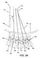
- FIG. 8is a schematic view of the step of inserting a threading hook tool over the first vertebra
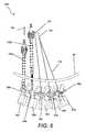
- FIG. 9is a schematic view of the step of engaging the adjacent vertebra with the hook tool of FIG. 8 ;
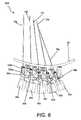
- FIG. 10is a schematic view of the step of threading a flexible wire through the hook tool of FIG. 8 ;
- FIG. 11is a magnified view of area A of FIG. 10 ;
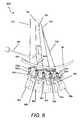
- FIG. 12is a schematic view of the step of removing the hook tool and leaving behind the threaded flexible wire
- FIG. 13is a schematic view of the step of inserting a push rod and pushing the flexible wire into the slot of the pedicle screw seat that was mounted in the pedicle of the first vertebra;
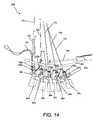
- FIG. 14is a schematic view of the step of inserting the flexible wire through the hook tool in the pedicle of the adjacent vertebra;
- FIG. 15is a schematic view of the step of inserting push rods and pushing the flexible wire into the slots of the seats of the pedicle screws that were mounted in the pedicles of the adjacent five vertebras;
- FIG. 16is a schematic view of the step of inserting portals over the pedicle screws that were mounted in the pedicles of the adjacent five vertebras;
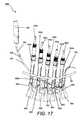
- FIG. 17is a schematic view of the step of inserting the stabilization rod through the portals that were mounted in the pedicles of the adjacent five vertebras;
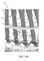
- FIG. 17Ais a magnified view of area A in FIG. 17 ;
- FIG. 18is a schematic view of the placed stabilization rod through the portals that were mounted in the pedicles of the adjacent five vertebras;
- FIG. 19is a schematic view of the pushed stabilization rod into the seats of the pedicle screws that were mounted in the pedicles of the adjacent five vertebras;
- FIG. 20is a schematic view of the step of securing the stabilization rod with set screws
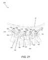
- FIG. 21is a schematic view of the step of removing the portals from the pedicles of the adjacent five vertebras
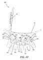
- FIG. 22is a schematic view of the step of breaking the spondi tabs
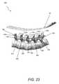
- FIG. 23is a schematic view of the inserted rod and pedicle screw fixation system
- FIG. 24is a schematic exploded side view of the portal unit
- FIG. 25Ais a perspective side view of the pedicle screw.
- FIG. 25 Bis an exploded view of the pedicle screw of FIG. 25A .
- the present inventionrelates to improved methods, tools and devices for spinal fixation, and more particularly to an improved method for spinal rod insertion.
- the improved method for spinal rod insertionincludes the following steps.
- a Jamshidi® needle 70is inserted into a pedicle 90 a of a first vertebra 80 a .
- the Jamshidi® needle 70penetrates the outer skin layers 60 , the underlying tissue layers 62 and is inserted into pedicles 90 a , 90 b , 90 c , 90 d and 90 e of adjacent vertebras 80 a , 80 b , 80 c , 80 d and 80 e , respectively, under radiographic imaging.
- guide wires 72 a , 72 b , 72 c , 72 d and 72 eare inserted over the needle 70 in the pedicle locations where the needle was inserted, as shown in FIG. 2 .
- tissue dilators 180 or 190are used to dilate the tissue around the guide wire locations, as shown in FIG. 3A and FIG. 3B .
- the tissue dilatormay be a cylindrical dilator 180 , shown in FIG. 3A or a flat blade dilator 190 , shown in FIG. 3B .
- the dilatorhas an elongated central opening extending through its main body and is inserted over the guide wire 72 a in each pedicle location.
- a tapping needle 195is used to make openings in the pedicle locations 90 a - 90 e , as shown in FIG.
- pedicle screw 130includes a threaded screw 132 , a washer 136 and a tulip-shaped seat 134 .
- the threaded screw 132includes a threaded body 131 a and a spherical head 131 a .
- the tulip-shaped seat 134includes a seat 134 having a slot 133 and breakable extensions (or tabs) 135 - 1 and 135 - 2 upward extending from its sides.
- the threaded screw 132passes through an opening formed in the bottom of the seat 134 and washer 136 is placed inside the seat 134 on top of the spherical head 131 a .
- the upper surface of washer 136is curved and its curvature is dimensioned to receive a cylindrical stabilization rod, as will be described below.
- Hook tool 100includes a handle 101 , a shaft 102 and a U-shaped hook end 110 configured to be inserted between two adjacent tissue openings 62 a , 62 b , as shown in FIG. 9 .
- U-shaped hook end 110includes two parallel legs 110 a , 110 b , that are separated from each other by a distance 113 , as shown in FIG. 11 .
- U-shaped hook endis formed from a cylindrical hollow tubing and the distance 113 between the two parallel legs 110 a , 110 b is approximately equal to the distance between two adjacent vertebras.
- leg 110 ais inserted into opening 62 b and then the hook tool is pushed into the cut fascia between vertebras 80 a , 80 b and leg 110 a exits through adjacent opening 92 a .
- a folded flexible wire 120is inserted into the U-shaped hook tube end 112 a and is threaded through the tube, as shown in FIG. 10 .
- Folded wire 120has two open ends 120 a , 120 b on the front and a closed loop end 120 c on the back, as shown in FIG. 18 and FIG. 17A .
- the closed loop end 120 cwas previously threaded through a loop 182 at the front end 180 a of the spinal stabilization rod 180 , as shown in FIG. 17 and FIG.
- the two front open ends 120 a , 120 b of the folded wire 120are pulled through the hollow U-shaped hook tube 110 and exit through the tube end 112 b , as shown in FIG. 10 and FIG. 11 .
- the hook tool 100is removed leaving behind the threaded flexible wire 120 , as shown in FIG. 12 , and then the wire 120 is pushed with tool 140 into the slot 133 of the tulip-shaped seat 134 of the pedicle screw 130 a , as shown in FIG. 13 .
- the process or threading the wire 120is repeated for the adjacent pedicle screw 130 b , as shown in FIG. 14 .
- wire 120is threaded through all pedicle screws 130 a , 130 b , 130 c , 130 d , 130 e and the two open ends 120 a , 120 b exit through the tissue opening 62 e over the last vertebra 80 e , as shown in FIG. 15 .
- portals 150 a , 150 b , 150 c , 150 d and 150 eare inserted through tissue openings 62 a , 62 b , 62 c , 62 d and 62 e and are placed over pedicle screws 130 a , 130 b , 130 c , 130 d , and 130 e , respectively.
- each portal 150includes an inner cannula 153 surrounded by an outer cannula 151 .
- Inner cannulaincludes a threaded top end 153 c and a cap 154 is threaded onto top end 153 c after the outer cannula is placed around it.
- Both inner and outer cannulas 153 , 151include slotted openings 153 d and 152 , respectively. Slotted openings 153 d , 152 in each portal 150 a , 150 b , 150 c , 150 d and 150 e are arranged in line with each other and form an elongated slot extending from the first portal 150 a to the last portal 150 e .
- a stabilizing rod 180is inserted with a rod push tool 160 through the slotted opening of the first portal 150 a into the space over vertebra 80 a .
- the front end 180 a of rod 180includes an opening 182 and wire 120 was previously threaded through the opening 182 , as was described above and shown in FIG. 17A .
- the wire 120is pulled from the open ends 120 a , 120 b exiting through tissue opening 62 e and in this way the rod 180 is pulled through the slotted openings of the adjacent portals 150 b , 150 c , 150 d and 150 e into the space over the adjacent vertebras 80 b , 80 c , 80 d , 80 e , respectively, as shown in FIG. 18 .
- the rod 180is pushed into the slots 133 of the pedicle screws 130 a , 130 b , 130 c , 130 d and 130 e with tools 140 a , 140 b , 140 c , 140 d and 140 e , respectively, as shown in FIG. 19 .
- set screwsare introduced through the portals 150 a , 150 b , 150 c , 150 d and 150 e into the seats of the pedicles screws 130 a , 130 b , 130 c , 130 d and 130 e , respectively, over the stabilization rod 180 and they are screwed into the seats to secure the stabilization rod, as shown in FIG. 20 , and then the portals are removed, as shown in FIG. 21 .
- the tabs 135 a , 135 b , 135 c , 135 d , 135 eare snapped away with tool 196 , as shown in FIG. 22 , leaving behind the secured stabilization rod 180 and the pedicle screws 130 a , 130 b , 130 c , 130 d and 130 e , as shown in FIG. 23 .
- the stabilization rod 180is inserted through the slotted openings of portals 150 a , 150 b , 150 c , 150 d and 150 e into the space over the adjacent vertebras 80 a , 80 b , 80 c , 80 d , 80 e , prior to the placement of the pedicle screws 130 a , 130 b , 130 c , 130 d and 130 e in the corresponding pedicle openings.
Landscapes
- Health & Medical Sciences (AREA)
- Orthopedic Medicine & Surgery (AREA)
- Surgery (AREA)
- Life Sciences & Earth Sciences (AREA)
- Heart & Thoracic Surgery (AREA)
- Animal Behavior & Ethology (AREA)
- Engineering & Computer Science (AREA)
- Biomedical Technology (AREA)
- Neurology (AREA)
- Medical Informatics (AREA)
- Molecular Biology (AREA)
- Nuclear Medicine, Radiotherapy & Molecular Imaging (AREA)
- General Health & Medical Sciences (AREA)
- Public Health (AREA)
- Veterinary Medicine (AREA)
- Dentistry (AREA)
- Oral & Maxillofacial Surgery (AREA)
- Prostheses (AREA)
- Surgical Instruments (AREA)
Abstract
Description
Claims (20)
Priority Applications (2)
| Application Number | Priority Date | Filing Date | Title |
|---|---|---|---|
| US13/527,557US8968319B2 (en) | 2011-06-20 | 2012-06-19 | Methods, tools and devices for spinal fixation |
| PCT/US2012/043240WO2012177691A2 (en) | 2011-06-20 | 2012-06-20 | Improved methods, tools and devices for spinal fixation |
Applications Claiming Priority (2)
| Application Number | Priority Date | Filing Date | Title |
|---|---|---|---|
| US201161498668P | 2011-06-20 | 2011-06-20 | |
| US13/527,557US8968319B2 (en) | 2011-06-20 | 2012-06-19 | Methods, tools and devices for spinal fixation |
Publications (2)
| Publication Number | Publication Date |
|---|---|
| US20120323280A1 US20120323280A1 (en) | 2012-12-20 |
| US8968319B2true US8968319B2 (en) | 2015-03-03 |
Family
ID=47354287
Family Applications (1)
| Application Number | Title | Priority Date | Filing Date |
|---|---|---|---|
| US13/527,557Active - Reinstated2032-09-08US8968319B2 (en) | 2011-06-20 | 2012-06-19 | Methods, tools and devices for spinal fixation |
Country Status (2)
| Country | Link |
|---|---|
| US (1) | US8968319B2 (en) |
| WO (1) | WO2012177691A2 (en) |
Cited By (2)
| Publication number | Priority date | Publication date | Assignee | Title |
|---|---|---|---|---|
| US11051857B2 (en) | 2017-08-10 | 2021-07-06 | Ortho Development Corporation | Tether clamping assemblies and related methods and apparatus |
| US11071569B2 (en) | 2017-08-10 | 2021-07-27 | Ortho Development Corporation | Nesting tether clamping assemblies and related methods and apparatus |
Families Citing this family (6)
| Publication number | Priority date | Publication date | Assignee | Title |
|---|---|---|---|---|
| US20130317557A1 (en)* | 2012-05-26 | 2013-11-28 | Custom Spine, Inc. | Mis rod insertion device and method |
| US20140088647A1 (en)* | 2012-09-21 | 2014-03-27 | Atlas Spine, Inc. | Minimally invasive spine surgery instruments: spinal rod with flange |
| WO2014066513A1 (en)* | 2012-10-23 | 2014-05-01 | Gordon Charles R | Method of positioning pedicle screws and spinal rods and apparatuses for the same |
| US20140277169A1 (en)* | 2013-03-14 | 2014-09-18 | Nadi Salah Hibri | Vertebral Implant |
| US20210220025A1 (en)* | 2016-01-18 | 2021-07-22 | Premia Spine Ltd. | Fusion rod insertion in percutaneous fusion surgery |
| US11819255B2 (en) | 2019-10-07 | 2023-11-21 | Ortho Development Corporation | Tether tensioning instrumentation and related methods |
Citations (27)
| Publication number | Priority date | Publication date | Assignee | Title |
|---|---|---|---|---|
| US6146386A (en)* | 1999-02-04 | 2000-11-14 | Sdgi Holdings, Inc. | Cable operated bone anchor compressor |
| US20050065517A1 (en)* | 2003-09-24 | 2005-03-24 | Chin Kingsley Richard | Methods and devices for improving percutaneous access in minimally invasive surgeries |
| US20050192570A1 (en) | 2004-02-27 | 2005-09-01 | Jackson Roger P. | Orthopedic implant rod reduction tool set and method |
| US20050215999A1 (en) | 2004-03-19 | 2005-09-29 | Depuy Spine, Inc. | Spinal fixation element and methods |
| US20060069391A1 (en) | 2004-02-27 | 2006-03-30 | Jackson Roger P | Spinal fixation tool attachment structure |
| US20060111712A1 (en) | 2004-11-23 | 2006-05-25 | Jackson Roger P | Spinal fixation tool set and method |
| US20060111713A1 (en) | 2004-11-23 | 2006-05-25 | Jackson Roger P | Spinal fixation tool set and method |
| US20060184178A1 (en) | 2004-02-27 | 2006-08-17 | Jackson Roger P | Orthopedic implant rod reduction tool set and method |
| US20070073294A1 (en) | 2003-09-24 | 2007-03-29 | Spinefrontier Lls | System and method for implanting spinal stabilization devices |
| US20070233079A1 (en) | 2006-02-06 | 2007-10-04 | Stryker Spine | Rod contouring apparatus and method for percutaneous pedicle screw extension |
| US20070288026A1 (en)* | 2006-06-09 | 2007-12-13 | Endius, Inc. | Methods and apparatus for access to and/or treatment of the spine |
| US20080077136A1 (en) | 2006-09-25 | 2008-03-27 | Stryker Spine | Rod inserter and rod with reduced diameter end |
| US20080082172A1 (en) | 2006-09-29 | 2008-04-03 | Jackson Roger P | Interspinous process spacer |
| US20080091213A1 (en) | 2004-02-27 | 2008-04-17 | Jackson Roger P | Tool system for dynamic spinal implants |
| US20080114403A1 (en) | 2006-11-09 | 2008-05-15 | Zimmer Spine, Inc. | Minimally invasive pedicle screw access system and associated method |
| US20080312704A1 (en) | 2007-06-12 | 2008-12-18 | Zimmer Spine, Inc. | Instrumentation and associated techniques for minimally invasive spinal construct installation |
| US20090012563A1 (en)* | 2006-10-11 | 2009-01-08 | Nas Medical Technologies, Inc. | Spinal fixation devices and methods |
| US20090171392A1 (en) | 2007-12-04 | 2009-07-02 | Javier Garcia-Bengochea | Guide wire mounting collar for spinal fixation using minimally invasive surgical techniques |
| US20090171391A1 (en) | 2007-10-23 | 2009-07-02 | Alphatec Spine, Inc. | Systems and methods for spinal fixation |
| US20090198281A1 (en) | 2008-02-05 | 2009-08-06 | Zimmer Spine, Inc. | System and method for insertion of flexible spinal stabilization element |
| US20100249856A1 (en) | 2009-03-27 | 2010-09-30 | Andrew Iott | Devices and Methods for Inserting a Vertebral Fixation Member |
| US7942878B2 (en)* | 2005-08-02 | 2011-05-17 | Synthes Usa, Llc | Two members cerclage tool |
| US8092461B2 (en)* | 2006-08-04 | 2012-01-10 | Magrod, Llc | Method and apparatus for facilitating navigation of an implant |
| US8267968B2 (en)* | 2009-06-24 | 2012-09-18 | Neuropro Technologies, Inc. | Percutaneous system for dynamic spinal stabilization |
| US8333771B2 (en)* | 2006-08-04 | 2012-12-18 | Magrod, Llc | System for pushing and pulling surgical implants into position in vivo via a tether |
| US8403963B2 (en)* | 2010-01-22 | 2013-03-26 | Javier Garcia-Bengochea | Method and apparatus for spinal fixation using minimally invasive surgical techniques |
| US20140018868A1 (en)* | 2007-12-06 | 2014-01-16 | Javier Garcia-Bengochea | Instrumentation for Spinal Fixation Using Minimally Invasive Surgical Techniques |
- 2012
- 2012-06-19USUS13/527,557patent/US8968319B2/enactiveActive - Reinstated
- 2012-06-20WOPCT/US2012/043240patent/WO2012177691A2/enactiveApplication Filing
Patent Citations (38)
| Publication number | Priority date | Publication date | Assignee | Title |
|---|---|---|---|---|
| US6146386A (en)* | 1999-02-04 | 2000-11-14 | Sdgi Holdings, Inc. | Cable operated bone anchor compressor |
| US20050065517A1 (en)* | 2003-09-24 | 2005-03-24 | Chin Kingsley Richard | Methods and devices for improving percutaneous access in minimally invasive surgeries |
| US20070073294A1 (en) | 2003-09-24 | 2007-03-29 | Spinefrontier Lls | System and method for implanting spinal stabilization devices |
| US7160300B2 (en) | 2004-02-27 | 2007-01-09 | Jackson Roger P | Orthopedic implant rod reduction tool set and method |
| US20060069391A1 (en) | 2004-02-27 | 2006-03-30 | Jackson Roger P | Spinal fixation tool attachment structure |
| US20100004696A1 (en) | 2004-02-27 | 2010-01-07 | Jackson Roger P | Orthopedic implant rod reduction tool set and method |
| US20060184178A1 (en) | 2004-02-27 | 2006-08-17 | Jackson Roger P | Orthopedic implant rod reduction tool set and method |
| US20060293680A1 (en) | 2004-02-27 | 2006-12-28 | Jackson Roger P | Orthopedic implant rod reduction tool set and method |
| US20080091213A1 (en) | 2004-02-27 | 2008-04-17 | Jackson Roger P | Tool system for dynamic spinal implants |
| US20090228056A1 (en) | 2004-02-27 | 2009-09-10 | Jackson Roger P | Orthopedic implant rod reduction tool set and method |
| US20050192570A1 (en) | 2004-02-27 | 2005-09-01 | Jackson Roger P. | Orthopedic implant rod reduction tool set and method |
| US20080288005A1 (en) | 2004-02-27 | 2008-11-20 | Jackson Roger P | Orthopedic implant rod reduction tool set and method |
| US20050215999A1 (en) | 2004-03-19 | 2005-09-29 | Depuy Spine, Inc. | Spinal fixation element and methods |
| US7621918B2 (en) | 2004-11-23 | 2009-11-24 | Jackson Roger P | Spinal fixation tool set and method |
| US20070032162A1 (en) | 2004-11-23 | 2007-02-08 | Jackson Roger P | Spinal fixation tool set and method |
| US20060111712A1 (en) | 2004-11-23 | 2006-05-25 | Jackson Roger P | Spinal fixation tool set and method |
| US20090318972A1 (en) | 2004-11-23 | 2009-12-24 | Jackson Roger P | Spinal fixation tool set and method |
| US20060111713A1 (en) | 2004-11-23 | 2006-05-25 | Jackson Roger P | Spinal fixation tool set and method |
| US7942878B2 (en)* | 2005-08-02 | 2011-05-17 | Synthes Usa, Llc | Two members cerclage tool |
| US20070233079A1 (en) | 2006-02-06 | 2007-10-04 | Stryker Spine | Rod contouring apparatus and method for percutaneous pedicle screw extension |
| US20090099605A1 (en) | 2006-02-06 | 2009-04-16 | Stryker Spine | Rod contouring apparatus for percutaneous pedicle screw extension |
| US20070288026A1 (en)* | 2006-06-09 | 2007-12-13 | Endius, Inc. | Methods and apparatus for access to and/or treatment of the spine |
| US20080015582A1 (en) | 2006-06-09 | 2008-01-17 | Endius, Inc. | Methods and apparatus for access to and/or treatment of the spine |
| US8333771B2 (en)* | 2006-08-04 | 2012-12-18 | Magrod, Llc | System for pushing and pulling surgical implants into position in vivo via a tether |
| US8092461B2 (en)* | 2006-08-04 | 2012-01-10 | Magrod, Llc | Method and apparatus for facilitating navigation of an implant |
| US20080077136A1 (en) | 2006-09-25 | 2008-03-27 | Stryker Spine | Rod inserter and rod with reduced diameter end |
| US20100145389A1 (en) | 2006-09-25 | 2010-06-10 | Stryker Spine | Rod inserter and rod with reduced diameter end |
| US20080082172A1 (en) | 2006-09-29 | 2008-04-03 | Jackson Roger P | Interspinous process spacer |
| US20090012563A1 (en)* | 2006-10-11 | 2009-01-08 | Nas Medical Technologies, Inc. | Spinal fixation devices and methods |
| US20080114403A1 (en) | 2006-11-09 | 2008-05-15 | Zimmer Spine, Inc. | Minimally invasive pedicle screw access system and associated method |
| US20080312704A1 (en) | 2007-06-12 | 2008-12-18 | Zimmer Spine, Inc. | Instrumentation and associated techniques for minimally invasive spinal construct installation |
| US20090171391A1 (en) | 2007-10-23 | 2009-07-02 | Alphatec Spine, Inc. | Systems and methods for spinal fixation |
| US20090171392A1 (en) | 2007-12-04 | 2009-07-02 | Javier Garcia-Bengochea | Guide wire mounting collar for spinal fixation using minimally invasive surgical techniques |
| US20140018868A1 (en)* | 2007-12-06 | 2014-01-16 | Javier Garcia-Bengochea | Instrumentation for Spinal Fixation Using Minimally Invasive Surgical Techniques |
| US20090198281A1 (en) | 2008-02-05 | 2009-08-06 | Zimmer Spine, Inc. | System and method for insertion of flexible spinal stabilization element |
| US20100249856A1 (en) | 2009-03-27 | 2010-09-30 | Andrew Iott | Devices and Methods for Inserting a Vertebral Fixation Member |
| US8267968B2 (en)* | 2009-06-24 | 2012-09-18 | Neuropro Technologies, Inc. | Percutaneous system for dynamic spinal stabilization |
| US8403963B2 (en)* | 2010-01-22 | 2013-03-26 | Javier Garcia-Bengochea | Method and apparatus for spinal fixation using minimally invasive surgical techniques |
Cited By (3)
| Publication number | Priority date | Publication date | Assignee | Title |
|---|---|---|---|---|
| US11051857B2 (en) | 2017-08-10 | 2021-07-06 | Ortho Development Corporation | Tether clamping assemblies and related methods and apparatus |
| US11071569B2 (en) | 2017-08-10 | 2021-07-27 | Ortho Development Corporation | Nesting tether clamping assemblies and related methods and apparatus |
| US11857221B2 (en) | 2017-08-10 | 2024-01-02 | Ortho Development Corporation | Nesting tether clamping assemblies and related methods and apparatus |
Also Published As
| Publication number | Publication date |
|---|---|
| WO2012177691A3 (en) | 2013-02-28 |
| US20120323280A1 (en) | 2012-12-20 |
| WO2012177691A2 (en) | 2012-12-27 |
Similar Documents
| Publication | Publication Date | Title |
|---|---|---|
| US8968319B2 (en) | Methods, tools and devices for spinal fixation | |
| US11849931B2 (en) | Methods and apparatus for access to and/or treatment of the spine | |
| US11241262B2 (en) | Methods and devices for spinal fixation element placement | |
| US9179926B2 (en) | Minimally invasive spinal fixation guide systems and methods | |
| US8052727B2 (en) | System and method for insertion of flexible spinal stabilization element | |
| US7875031B2 (en) | System and method for implanting spinal stabilization devices | |
| US8277491B2 (en) | Methods and devices for minimally invasive spinal fixation element placement | |
| US8202302B2 (en) | Pedicle screw and rod system | |
| US20050228380A1 (en) | Instruments and methods for minimally invasive spine surgery | |
| KR20070112200A (en) | Implants in surgical approach to the spine and methods for positioning them | |
| CN111887967A (en) | Percutaneous Transconnector System | |
| KR101631908B1 (en) | Surgical method for fixing a screw to a pedicle and instruments for inserting a screw which is used for the same | |
| US9161781B2 (en) | Minimally invasive percutaneous pedicle screw and slotted rod assembly |
Legal Events
| Date | Code | Title | Description |
|---|---|---|---|
| AS | Assignment | Owner name:SPINEFRONTIER INC, MASSACHUSETTS Free format text:ASSIGNMENT OF ASSIGNORS INTEREST;ASSIGNORS:CHIN, KINGSLEY R.;IBARRA, MATTHEW;HENSHAW, CRAIG;AND OTHERS;SIGNING DATES FROM 20110627 TO 20110822;REEL/FRAME:033492/0211 | |
| STCF | Information on status: patent grant | Free format text:PATENTED CASE | |
| AS | Assignment | Owner name:MIDCAP BUSINESS CREDIT LLC, CONNECTICUT Free format text:ASSIGNMENT OF ASSIGNORS INTEREST;ASSIGNOR:SPINEFRONTIER, INC.;REEL/FRAME:037598/0935 Effective date:20151229 | |
| MAFP | Maintenance fee payment | Free format text:PAYMENT OF MAINTENANCE FEE, 4TH YR, SMALL ENTITY (ORIGINAL EVENT CODE: M2551); ENTITY STATUS OF PATENT OWNER: SMALL ENTITY Year of fee payment:4 | |
| AS | Assignment | Owner name:KIC VENTURES, LLC, MASSACHUSETTS Free format text:ASSIGNMENT OF ASSIGNORS INTEREST;ASSIGNOR:SPINEFRONTIER, INC;REEL/FRAME:053972/0737 Effective date:20190701 | |
| AS | Assignment | Owner name:SPINEFRONTIER, INC., MASSACHUSETTS Free format text:RELEASE BY SECURED PARTY;ASSIGNOR:MIDCAP BUSINESS CREDIT LLC;REEL/FRAME:053998/0119 Effective date:20170505 Owner name:MIDCAP BUSINESS CREDIT LLC, CONNECTICUT Free format text:CORRECTIVE ASSIGNMENT TO CORRECT THE COVER SHEET. IT WASRECORDED AS AN ASSIGNMENT; HOWEVER, IT IS A SECURITY INTEREST. PREVIOUSLY RECORDED ON REEL 037598 FRAME 0935. ASSIGNOR(S) HEREBY CONFIRMS THE PATENT SECURITY AGREEMENT;ASSIGNOR:SPINEFRONTIER, INC.;REEL/FRAME:054001/0506 Effective date:20151229 | |
| AS | Assignment | Owner name:SPINEFRONTIER, INC., MASSACHUSETTS Free format text:RELEASE BY SECURED PARTY;ASSIGNOR:MIDCAP BUSINESS CREDIT LLC;REEL/FRAME:054064/0310 Effective date:20201008 | |
| FEPP | Fee payment procedure | Free format text:MAINTENANCE FEE REMINDER MAILED (ORIGINAL EVENT CODE: REM.); ENTITY STATUS OF PATENT OWNER: SMALL ENTITY | |
| PRDP | Patent reinstated due to the acceptance of a late maintenance fee | Effective date:20230307 | |
| FEPP | Fee payment procedure | Free format text:PETITION RELATED TO MAINTENANCE FEES FILED (ORIGINAL EVENT CODE: PMFP); ENTITY STATUS OF PATENT OWNER: SMALL ENTITY Free format text:PETITION RELATED TO MAINTENANCE FEES GRANTED (ORIGINAL EVENT CODE: PMFG); ENTITY STATUS OF PATENT OWNER: SMALL ENTITY Free format text:SURCHARGE, PETITION TO ACCEPT PYMT AFTER EXP, UNINTENTIONAL. (ORIGINAL EVENT CODE: M2558); ENTITY STATUS OF PATENT OWNER: SMALL ENTITY | |
| MAFP | Maintenance fee payment | Free format text:PAYMENT OF MAINTENANCE FEE, 8TH YR, SMALL ENTITY (ORIGINAL EVENT CODE: M2552); ENTITY STATUS OF PATENT OWNER: SMALL ENTITY Year of fee payment:8 |