US8968288B2 - Ablation devices with dual operating frequencies, systems including same, and methods of adjusting ablation volume using same - Google Patents
Ablation devices with dual operating frequencies, systems including same, and methods of adjusting ablation volume using sameDownload PDFInfo
- Publication number
- US8968288B2 US8968288B2US12/709,014US70901410AUS8968288B2US 8968288 B2US8968288 B2US 8968288B2US 70901410 AUS70901410 AUS 70901410AUS 8968288 B2US8968288 B2US 8968288B2
- Authority
- US
- United States
- Prior art keywords
- balun
- ablation device
- electrically
- ablation
- inner conductor
- Prior art date
- Legal status (The legal status is an assumption and is not a legal conclusion. Google has not performed a legal analysis and makes no representation as to the accuracy of the status listed.)
- Active, expires
Links
Images


Classifications
- A—HUMAN NECESSITIES
- A61—MEDICAL OR VETERINARY SCIENCE; HYGIENE
- A61B—DIAGNOSIS; SURGERY; IDENTIFICATION
- A61B18/00—Surgical instruments, devices or methods for transferring non-mechanical forms of energy to or from the body
- A61B18/04—Surgical instruments, devices or methods for transferring non-mechanical forms of energy to or from the body by heating
- A61B18/08—Surgical instruments, devices or methods for transferring non-mechanical forms of energy to or from the body by heating by means of electrically-heated probes
- A—HUMAN NECESSITIES
- A61—MEDICAL OR VETERINARY SCIENCE; HYGIENE
- A61B—DIAGNOSIS; SURGERY; IDENTIFICATION
- A61B18/00—Surgical instruments, devices or methods for transferring non-mechanical forms of energy to or from the body
- A61B18/04—Surgical instruments, devices or methods for transferring non-mechanical forms of energy to or from the body by heating
- A61B18/12—Surgical instruments, devices or methods for transferring non-mechanical forms of energy to or from the body by heating by passing a current through the tissue to be heated, e.g. high-frequency current
- A61B18/14—Probes or electrodes therefor
- A61B18/149—Probes or electrodes therefor bow shaped or with rotatable body at cantilever end, e.g. for resectoscopes, or coagulating rollers
- A—HUMAN NECESSITIES
- A61—MEDICAL OR VETERINARY SCIENCE; HYGIENE
- A61B—DIAGNOSIS; SURGERY; IDENTIFICATION
- A61B18/00—Surgical instruments, devices or methods for transferring non-mechanical forms of energy to or from the body
- A61B18/18—Surgical instruments, devices or methods for transferring non-mechanical forms of energy to or from the body by applying electromagnetic radiation, e.g. microwaves
- A61B18/1815—Surgical instruments, devices or methods for transferring non-mechanical forms of energy to or from the body by applying electromagnetic radiation, e.g. microwaves using microwaves
- A—HUMAN NECESSITIES
- A61—MEDICAL OR VETERINARY SCIENCE; HYGIENE
- A61B—DIAGNOSIS; SURGERY; IDENTIFICATION
- A61B18/00—Surgical instruments, devices or methods for transferring non-mechanical forms of energy to or from the body
- A61B2018/00005—Cooling or heating of the probe or tissue immediately surrounding the probe
- A61B2018/00011—Cooling or heating of the probe or tissue immediately surrounding the probe with fluids
- A61B2018/00023—Cooling or heating of the probe or tissue immediately surrounding the probe with fluids closed, i.e. without wound contact by the fluid
- A—HUMAN NECESSITIES
- A61—MEDICAL OR VETERINARY SCIENCE; HYGIENE
- A61B—DIAGNOSIS; SURGERY; IDENTIFICATION
- A61B18/00—Surgical instruments, devices or methods for transferring non-mechanical forms of energy to or from the body
- A61B2018/00053—Mechanical features of the instrument of device
- A61B2018/00059—Material properties
- A61B2018/00071—Electrical conductivity
- A61B2018/00077—Electrical conductivity high, i.e. electrically conducting
- A—HUMAN NECESSITIES
- A61—MEDICAL OR VETERINARY SCIENCE; HYGIENE
- A61B—DIAGNOSIS; SURGERY; IDENTIFICATION
- A61B18/00—Surgical instruments, devices or methods for transferring non-mechanical forms of energy to or from the body
- A61B2018/00571—Surgical instruments, devices or methods for transferring non-mechanical forms of energy to or from the body for achieving a particular surgical effect
- A61B2018/00577—Ablation
- A—HUMAN NECESSITIES
- A61—MEDICAL OR VETERINARY SCIENCE; HYGIENE
- A61B—DIAGNOSIS; SURGERY; IDENTIFICATION
- A61B18/00—Surgical instruments, devices or methods for transferring non-mechanical forms of energy to or from the body
- A61B2018/00571—Surgical instruments, devices or methods for transferring non-mechanical forms of energy to or from the body for achieving a particular surgical effect
- A61B2018/00595—Cauterization
- A—HUMAN NECESSITIES
- A61—MEDICAL OR VETERINARY SCIENCE; HYGIENE
- A61B—DIAGNOSIS; SURGERY; IDENTIFICATION
- A61B18/00—Surgical instruments, devices or methods for transferring non-mechanical forms of energy to or from the body
- A61B2018/00636—Sensing and controlling the application of energy
- A61B2018/00696—Controlled or regulated parameters
- A61B2018/00738—Depth, e.g. depth of ablation
- A—HUMAN NECESSITIES
- A61—MEDICAL OR VETERINARY SCIENCE; HYGIENE
- A61B—DIAGNOSIS; SURGERY; IDENTIFICATION
- A61B18/00—Surgical instruments, devices or methods for transferring non-mechanical forms of energy to or from the body
- A61B2018/0091—Handpieces of the surgical instrument or device
- A61B2018/00916—Handpieces of the surgical instrument or device with means for switching or controlling the main function of the instrument or device
- A61B2018/0094—Types of switches or controllers
- A—HUMAN NECESSITIES
- A61—MEDICAL OR VETERINARY SCIENCE; HYGIENE
- A61B—DIAGNOSIS; SURGERY; IDENTIFICATION
- A61B18/00—Surgical instruments, devices or methods for transferring non-mechanical forms of energy to or from the body
- A61B18/18—Surgical instruments, devices or methods for transferring non-mechanical forms of energy to or from the body by applying electromagnetic radiation, e.g. microwaves
- A61B18/1815—Surgical instruments, devices or methods for transferring non-mechanical forms of energy to or from the body by applying electromagnetic radiation, e.g. microwaves using microwaves
- A61B2018/183—Surgical instruments, devices or methods for transferring non-mechanical forms of energy to or from the body by applying electromagnetic radiation, e.g. microwaves using microwaves characterised by the type of antenna
- A61B2018/1853—Monopole antennas
- A—HUMAN NECESSITIES
- A61—MEDICAL OR VETERINARY SCIENCE; HYGIENE
- A61B—DIAGNOSIS; SURGERY; IDENTIFICATION
- A61B18/00—Surgical instruments, devices or methods for transferring non-mechanical forms of energy to or from the body
- A61B18/18—Surgical instruments, devices or methods for transferring non-mechanical forms of energy to or from the body by applying electromagnetic radiation, e.g. microwaves
- A61B18/1815—Surgical instruments, devices or methods for transferring non-mechanical forms of energy to or from the body by applying electromagnetic radiation, e.g. microwaves using microwaves
- A61B2018/1861—Surgical instruments, devices or methods for transferring non-mechanical forms of energy to or from the body by applying electromagnetic radiation, e.g. microwaves using microwaves with an instrument inserted into a body lumen or cavity, e.g. a catheter
- A—HUMAN NECESSITIES
- A61—MEDICAL OR VETERINARY SCIENCE; HYGIENE
- A61B—DIAGNOSIS; SURGERY; IDENTIFICATION
- A61B18/00—Surgical instruments, devices or methods for transferring non-mechanical forms of energy to or from the body
- A61B18/18—Surgical instruments, devices or methods for transferring non-mechanical forms of energy to or from the body by applying electromagnetic radiation, e.g. microwaves
- A61B18/1815—Surgical instruments, devices or methods for transferring non-mechanical forms of energy to or from the body by applying electromagnetic radiation, e.g. microwaves using microwaves
- A61B2018/1876—Surgical instruments, devices or methods for transferring non-mechanical forms of energy to or from the body by applying electromagnetic radiation, e.g. microwaves using microwaves with multiple frequencies
Definitions
- the present disclosurerelates to electrosurgical devices suitable for use in tissue ablation applications and, more particularly, to ablation devices with dual operating frequencies, systems including the same, and methods of adjusting ablation volume using the same.
- Electromagnetic radiationcan be used to heat and destroy tumor cells. Treatment may involve inserting ablation probes into tissues where cancerous tumors have been identified. Once the probes are positioned, electromagnetic energy is passed through the probes into surrounding tissue.
- microwave apparatusfor use in ablation procedures include a microwave generator that functions as an energy source, and a microwave surgical instrument (e.g., microwave ablation probe) having an antenna assembly for directing the energy to the target tissue.
- the microwave generator and surgical instrumentare typically operatively coupled by a cable assembly having a plurality of conductors for transmitting microwave energy from the generator to the instrument, and for communicating control, feedback and identification signals between the instrument and the generator.
- monopole and dipole antenna assembliesmicrowave energy generally radiates perpendicularly away from the axis of the conductor.
- Monopole antenna assembliestypically include a single, elongated conductor.
- a typical dipole antenna assemblyincludes two elongated conductors that are linearly-aligned and positioned end-to-end relative to one another with an electrical insulator placed therebetween.
- Helical antenna assembliesinclude helically-shaped conductor configurations of various dimensions, e.g., diameter and length.
- the main modes of operation of a helical antenna assemblyare normal mode (broadside), in which the field radiated by the helix is maximum in a perpendicular plane to the helix axis, and axial mode (end fire), in which maximum radiation is along the helix axis.
- tissue ablation proceduremay dictate a particular ablation volume in order to achieve a desired surgical outcome.
- Ablation volumeis correlated with antenna design, antenna performance, antenna impedance, ablation time and wattage, and tissue characteristics, e.g., tissue impedance.
- the transference or dispersion of heatgenerally may occur by mechanisms of radiation, conduction, and convection.
- “Thermal radiation” and “radiative heat transfer”are two terms used to describe the transfer of energy in the form of electromagnetic waves (e.g., as predicted by electromagnetic wave theory) or photons (e.g., as predicted by quantum mechanics).
- the term “conduction”generally refers to the transfer of energy from more energetic to less energetic particles of substances due to interactions between the particles.
- the term “convection”generally refers to the energy transfer between a solid surface and an adjacent moving fluid. Convection heat transfer may be a combination of diffusion or molecular motion within the fluid and the bulk or macroscopic motion of the fluid.
- the extent of tissue heatingmay depend on several factors including the rate at which energy is absorbed by, or dissipated in, the tissue under treatment.
- the electromagnetic-energy absorption rate in biological tissuemay be quantified by the specific absorption rate (SAR), a measure of the energy per unit mass absorbed by tissue and is usually expressed in units of watts per kilogram (W/kg).
- SARspecific absorption rate
- One method to determine the SARis to measure the rate of temperature rise in tissue as a function of the specific heat capacity of the tissue. This method requires knowledge of the specific heat of the tissue.
- a second methodis to determine the SAR by measuring the electric field strength in tissue. This method requires knowledge of the conductivity and density values of the tissue.
- modifying the local electric-field amplitudedirectly affects the local energy absorption and induced temperature rise in tissue.
- Fluid-cooled or dielectrically-buffered microwave devicesmay be used in ablation procedures.
- a microwave ablation deviceif proper cooling is not maintained, e.g., flow of coolant or buffering fluid is interrupted, the microwave ablation device may exhibit rapid failures due to the heat generated from the increased reflected power. Cooling the ablation probe may enhance the overall heating pattern of the antenna and prevent damage to the antenna.
- Tissue ablation devicescapable of influencing the SAR and the ablation volume may enable more precise ablation treatments, which may lead to shorter patient recovery times, fewer complications from undesired tissue damage, and improved patient outcomes.
- the present disclosurerelates to an ablation device including a feedline that includes an inner conductor having a distal end, an outer conductor coaxially disposed around the inner conductor, and a dielectric material disposed therebetween.
- the ablation devicealso includes an elongated electrically-conductive member longitudinally disposed at the distal end of the inner conductor and having a proximal end, a first balun structure disposed over a first portion of the outer conductor and positioned so that a distal end of the first balun structure is located at a first distance from the proximal end of the electrically-conductive member, and a second balun structure disposed over a second portion of the outer conductor and positioned so that a distal end of the second balun structure is located at a second distance from the proximal end of the electrically-conductive member.
- the present disclosurerelates to a system including a generator assembly and an ablation device operably associated with the generator assembly.
- the ablation deviceincludes a feedline having an inner conductor, an outer conductor coaxially disposed around the inner conductor, and a dielectric material disposed therebetween.
- the ablation devicealso includes a first balun structure operably associated with a first operating frequency, wherein the first balun structure is electrically coupled to the outer conductor, and a second balun structure operably associated with the second operating frequency, wherein the second balun structure is electrically coupled to the outer conductor.
- the present disclosurealso relates to a method of adjusting ablation volume including the initial step of positioning in tissue an ablation device capable of operating at a first operating frequency and a second operating frequency.
- the ablation deviceincludes an antenna assembly configured with a first balun operably associated with the first operating frequency and a second balun operably associated with the second operating frequency.
- the methodalso includes the steps of transmitting energy from an energy source through the antenna assembly to tissue at the first operating frequency, and transmitting energy from the energy source through the antenna assembly to tissue at the second operating frequency.
- FIG. 1is a schematic diagram of an ablation system in accordance with an embodiment of the present disclosure
- FIG. 2is a partial, longitudinal cross-sectional view of an embodiment of the energy applicator of the ablation system shown in FIG. 1 in accordance with the present disclosure
- FIG. 3is a schematic diagram of another embodiment of an ablation system in accordance with the present disclosure.
- FIG. 4is a perspective view with parts disassembled of a portion of an energy applicator according to an embodiment of the present disclosure
- FIG. 5is a perspective, assembled view of the energy applicator of FIG. 4 shown with first and second dielectric layers disposed about first and second portions of the outer conductor, respectively, according to an embodiment of the present disclosure
- FIG. 6Ais a perspective view of the energy applicator of FIG. 5 shown with first and second electrically-conductive layers disposed about the first and second dielectric layers, respectively, according to an embodiment of the present disclosure
- FIG. 6Bis a perspective view of the energy applicator of FIG. 6A shown with a third balun structure according to an embodiment of the present disclosure
- FIG. 7is a partial, perspective view of an embodiment of an ablation device including the portion of the energy applicator of FIG. 6A shown surrounded by an outer dielectric layer and disposed within an outer jacket in accordance with the present disclosure;
- FIG. 8is an enlarged, cross-sectional view of the indicated area of detail of FIG. 7 according to an embodiment of the present disclosure
- FIG. 9is an enlarged, cross-sectional view of the indicated area of detail of FIG. 7 according to an embodiment of the present disclosure.
- FIG. 10shows a diagram of a microwave ablation system that includes a user interface for displaying and controlling ablation patterns in accordance with the present disclosure
- FIG. 11is a block diagram of a microwave ablation system in accordance with the present disclosure.
- FIG. 12is a flowchart illustrating a method of directing energy to tissue according to an embodiment of the present disclosure.
- proximalrefers to that portion of the ablation device, or component thereof, closer to the user and the term “distal” refers to that portion of the ablation device, or component thereof, farther from the user.
- a phrase in the form “NB”means A or B.
- a phrase in the form “A and/or B”means “(A), (B), or (A and B)”.
- a phrase in the form “at least one of A, B, or C”means “(A), (B), (C), (A and B), (A and C), (B and C), or (A, B and C)”.
- Electromagnetic energyis generally classified by increasing energy or decreasing wavelength into radio waves, microwaves, infrared, visible light, ultraviolet, X-rays and gamma-rays.
- microwavegenerally refers to electromagnetic waves in the frequency range of 300 megahertz (MHz) (3 ⁇ 10 8 cycles/second) to 300 gigahertz (GHz) (3 ⁇ 10 11 cycles/second).
- ablation proceduregenerally refers to any ablation procedure, such as microwave ablation, radio frequency (RF) ablation or microwave ablation assisted resection.
- energy applicatorgenerally refers to any device that can be used to transfer energy from a power generating source, such as a microwave or RF electrosurgical generator, to tissue.
- energy applicator arraygenerally refers to one or more energy applicators.
- transmission linegenerally refers to any transmission medium that can be used for the propagation of signals from one point to another.
- fluidgenerally refers to a liquid, a gas or both.
- lengthmay refer to electrical length or physical length.
- electrical lengthis an expression of the length of a transmission medium in terms of the wavelength of a signal propagating within the medium. Electrical length is normally expressed in terms of wavelength, radians or degrees. For example, electrical length may be expressed as a multiple or sub-multiple of the wavelength of an electromagnetic wave or electrical signal propagating within a transmission medium. The wavelength may be expressed in radians or in artificial units of angular measure, such as degrees.
- the electric length of a transmission mediummay be expressed as its physical length multiplied by the ratio of (a) the propagation time of an electrical or electromagnetic signal through the medium to (b) the propagation time of an electromagnetic wave in free space over a distance equal to the physical length of the medium.
- the electrical lengthis in general different from the physical length. By the addition of an appropriate reactive element (capacitive or inductive), the electrical length may be made significantly shorter or longer than the physical length.
- Various embodiments of the present disclosureprovide ablation devices with dual operating frequencies for treating tissue and methods of directing electromagnetic radiation to tissue.
- the presently disclosed ablation deviceaccording to various embodiments is configured with a first balun structure operably associated with a first operating frequency and a second balun structure operably associated with a second operating frequency.
- the teachings of the present disclosuremay also apply to ablation devices with a plurality of operating frequencies.
- Embodimentsmay be implemented using electromagnetic radiation at microwave frequencies or at other frequencies.
- the presently disclosed ablation deviceis capable of operating at a first operating frequency of about 915 MHz and a second operating frequency of about 2.45 GHz.
- the second operating frequencymay be about 5.8 GHz.
- the presently disclosed ablation deviceis capable of operating at a first operating frequency of about 915 MHz, a second operating frequency of about 2.45 GHz and a third operating frequency of about 5.8 GHz.
- An electrosurgical system including the presently disclosed ablation device in fluid communication with a coolant supply system according to various embodimentsis designed and configured to operate at frequencies between about 500 MHz and about 10 GHz.
- Various embodiments of the presently disclosed ablation device with dual operating frequenciesare suitable for microwave ablation and for use to pre-coagulate tissue for microwave ablation-assisted surgical resection.
- various methods described hereinbeloware targeted toward microwave ablation and the complete destruction of target tissue, it is to be understood that methods for directing electromagnetic radiation may be used with other therapies in which the target tissue is partially destroyed or damaged, such as, for example, to prevent the conduction of electrical impulses within heart tissue.
- a dipole microwave antennathe teachings of the present disclosure may also apply to a monopole, helical, or other suitable type of microwave antenna.
- FIG. 1shows an electrosurgical system 10 , according to an embodiment of the present disclosure that includes an energy applicator or probe 101 .
- An embodiment of an energy applicator, such as the probe 101 of FIG. 1in accordance with the present disclosure, is shown in more detail in FIG. 2 . It will be understood, however, that other probe embodiments may also be used (e.g., 301 and 701 shown in FIGS. 3 and 7 , respectively).
- Probe 101generally includes an antenna assembly 12 having a radiating portion connected by a feedline 110 (or shaft) via a transmission line 15 to a connector 16 , which may further operably connect the probe 101 to an electrosurgical power generating source 28 , e.g., a microwave or RF electrosurgical generator.
- the probe 101may include a first balun structure “B 1 ” having a length “L 4 ” and a second balun structure “B 2 ” having a length “L 6 ”.
- the first balun structure “B 1 ”may be a quarter-wave sleeve balun or a half-wave sleeve balun.
- the second balun structure “B 2 ”may be a quarter-wave sleeve balun or a half-wave sleeve balun.
- the shape, size and relative positions of the first balun structure “B 1 ” and the second balun structure “B 2 ”, which are described in more detail later in this disclosure,may be varied from the configuration depicted in FIG. 2 .
- Feedline 110may be formed from a suitable flexible, semi-rigid or rigid microwave conductive cable and may connect directly to an electrosurgical power generating source 28 . Alternatively, the feedline 110 may electrically connect the antenna assembly 12 via the transmission line 15 and connector 11 to the electrosurgical power generating source 28 . Feedline 110 may have a variable length from a proximal end of the antenna assembly 12 to a distal end of transmission line 15 ranging from a length of about one inch to about twelve inches. Feedline 110 may be formed of suitable electrically-conductive materials, e.g., copper, gold, silver or other conductive metals or metal alloys having similar conductivity values. Feedline 110 may be made of stainless steel, which generally offers the strength required to puncture tissue and/or skin.
- Conductive materials used to form the feedline 110may be plated with other materials, e.g., other conductive materials, such as gold or silver, to improve their properties, e.g., to improve conductivity, decrease energy loss, etc.
- the feedline 110includes stainless steel, and to improve the conductivity thereof, the stainless steel may be coated with a layer of a conductive material such as copper or gold.
- Feedline 110may include an inner conductor 210 , a dielectric material 280 coaxially surrounding the inner conductor 210 , and an outer conductor 260 coaxially surrounding the dielectric material 280 .
- Antenna assembly 12may be formed from a portion of the inner conductor 210 that extends distal to the feedline 110 into the antenna assembly 12 .
- Dielectric material 280may be formed from any suitable dielectric material, including, but not limited to, ceramics, water, mica, polyethylene, polyethylene terephthalate, polyimide, polytetrafluoroethylene (PTFE) (e.g., Teflon®, manufactured by E. I. du Pont de Nemours and Company of Wilmington, Del., United States), glass, or metal oxides.
- PTFEpolytetrafluoroethylene
- Inner conductor 210 and the outer conductor 260may be formed from any suitable electrically conductive material.
- the inner conductor 210is formed from a first electrically conductive material (e.g., stainless steel) and the outer conductor 260 is formed from a second electrically conductive material (e.g., copper).
- Feedline 110may be cooled by fluid, e.g., saline, water or other suitable coolant fluid, to improve power handling, and may include a stainless steel catheter.
- the presently disclosed antenna assembly 12includes an elongated electrically-conductive element 270 .
- the electrically-conductive element 270is a solid metal cylinder that is electrically coupled to the inner conductor 210 (e.g., by solder).
- Electrically-conductive element 270may be formed of any suitable electrically-conductive material (e.g., metal such as stainless steel, aluminum, titanium, copper, etc.) of any suitable length “L 0 ”. The shape and size of the electrically-conductive element 270 may be varied from the configuration depicted in FIG. 2 .
- the power generating source 28is configured to provide microwave energy at an operational frequency from about 500 MHz to about 2500 MHz. In other embodiments, the power generating source 28 is configured to provide microwave energy at an operational frequency from about 500 MHz to about 10 GHz. Power generating source 28 may be configured to provide various frequencies of electromagnetic energy. Transmission line 15 may additionally, or alternatively, provide a conduit (not shown) configured to provide coolant fluid from a coolant source 18 to one or more components of the probe 101 .
- An end cap or tapered portion 120 located at the distal end of the antenna assembly 12terminates in a sharp tip 123 to allow for insertion into tissue with minimal resistance.
- the end cap or tapered portion 120may include other shapes, such as, for example, a tip 123 that is rounded, flat, square, hexagonal, or cylindroconical.
- the antenna assembly 12includes a distal radiating portion 105 and a proximal radiating portion 140 .
- a junction member 130may be disposed between the proximal and distal radiating portions, 140 and 105 , respectively.
- the distal and proximal radiating portions 105 , 140align at the junction member 130 , which is generally made of a dielectric material, e.g., adhesives, and are also supported by the inner conductor that extends at least partially through the distal radiating portion 105 .
- Junction member 130may have any suitable length “L 1 ”, and may be formed from any suitable elastomeric or ceramic dielectric material by any suitable process.
- the junction member 130is formed by over-molding and includes a thermoplastic elastomer, such as, for example, polyether block amide (e.g., PEBAX®, manufactured by The Arkema Group of Colombes, France), polyetherimide (e.g., ULTEM® and/or EXTEM®, manufactured by SABIC Innovative Plastics of Saudi Arabia) and/or polyimide-based polymer (e.g., VESPEL®, manufactured by E. I. du Pont de Nemours and Company of Wilmington, Del., United States).
- Junction member 130may be formed using any suitable over-molding compound by any suitable process, and may include use of a ceramic substrate.
- the presently disclosed antenna assembly 12includes a first balun structure “B 1 ” having a length “L 4 ” and a second balun structure “B 2 ” having a length “L 6 ” disposed proximal to the first balun structure “B 1 ”.
- the second balun structure “B 2 ”may be spaced apart, by a length “L 5 ”, from the first balun structure “B 1 ”.
- the second balun structure “B 2 ”, or portions thereofmay overlap the first balun structure “B 1 ”, or portions thereof.
- the distal end of the second balun structure “B 2 ”may be disposed substantially adjacent to the proximal end of the first balun structure “B 1 ”.
- the first balun structure “B 1 ”may be spaced apart, by a length “L 3 ”, from the proximal end of the electrically-conductive element 270 .
- the first balun structure “B 1 ”may be spaced apart, by a length “L 2 ”, from the proximal end of the junction member 130 .
- First balun structure “B 1 ”includes a first balun insulator 220 disposed about the outer conductor 260 , and a first electrically-conductive layer 240 (also referred to herein as a first conductive balun sleeve) disposed about the first balun insulator 220 , or portions thereof.
- First conductive balun sleeve 240is electrically coupled to the outer conductor 260 , e.g., by solder or other suitable electrical connection.
- Second balun structure “B 2 ”includes a second balun insulator 230 disposed about the outer conductor 260 , and a second electrically-conductive layer 250 (also referred to herein as a second conductive balun sleeve) disposed about the second balun insulator 230 , or portions thereof.
- Second conductive balun sleeve 250is electrically coupled to the outer conductor 260 using any suitable electrical connection.
- the proximal end of the first conductive balun sleeve 240 and/or the proximal end of the second conductive balun sleeve 250may be adapted to allow for connection, e.g., electrically and mechanically, to the outer conductor 260 .
- First and second balun insulators 220 and 230may be formed of any suitable insulative material, including, but not limited to, ceramics, water, mica, polyethylene, polyethylene terephthalate, polyimide, polytetrafluoroethylene (PTFE) (e.g., Teflon®, manufactured by E. I. du Pont de Nemours and Company of Wilmington, Del., United States), glass, metal oxides or other suitable insulator, and may be formed in any suitable manner.
- First and second balun insulators 220 , 230may be grown, deposited or formed by any other suitable technique.
- first and second balun insulators 220 , 230are formed from a material with a dielectric constant in the range of about 1.7 to about 10.
- First and second electrically-conductive layers 240 and 250may be formed of any suitable electrically-conductive material, e.g., metal such as stainless steel, titanium, copper, etc., and may be formed in any suitable manner.
- the antenna assembly 12may be provided with a coolant chamber (e.g., 271 shown in FIG. 2 ). Additionally, the junction member 130 may include coolant inflow and outflow ports (not shown) to facilitate the flow of coolant into, and out of, the coolant chamber. Examples of coolant chamber and coolant inflow and outflow port embodiments are disclosed in commonly assigned U.S. patent application Ser. No. 12/401,268 filed on Mar. 10, 2009, entitled “COOLED DIELECTRICALLY BUFFERED MICROWAVE DIPOLE ANTENNA”, and U.S. Pat. No. 7,311,703, entitled “DEVICES AND METHODS FOR COOLING MICROWAVE ANTENNAS”, the disclosures of which are incorporated herein by reference in their entireties.
- the antenna assembly 12may be provided with an outer dielectric layer (e.g., 285 shown in FIG. 2 ) disposed about the proximal radiating portion 140 , the junction 130 , and/or the distal radiating portion 105 , or portions thereof.
- the outer dielectric layermay be formed of any suitable material, such as, for example, polymeric or ceramic materials.
- the outer dielectric layermay be applied by any suitable method, such as, for example, heat shrinking, over-molding, coating, spraying dipping, powder coating, baking and/or film deposition.
- the antenna assembly 12includes an outer jacket 291 .
- Outer jacket 291may have a substantially cylindrical or tubular shape.
- the distal end of the outer jacket 291is adapted to be coupleable to an end cap or tapered portion 120 , e.g., by an O-ring “O”, or other suitable connection method or device.
- Outer jacket 291 and the end cap or tapered portion 120may be formed as a single structure. The shape and size of the outer jacket 291 and the tapered portion 120 may be varied from the configuration depicted in FIG. 2 .
- Outer jacket 291may be a fluid-cooled catheter formed of a composite material having low electrical conductivity, e.g., glass-reinforced polymers.
- a coolant chamber 271is defined between the outer dielectric layer 285 and the outer jacket 291 .
- Coolant chamber 271may be adapted to circulate coolant fluid “F” around the electrically-conductive element 270 .
- Coolant fluid “F”may be any suitable fluid that can be used for cooling or buffering the probe 101 , e.g., deionized water, or other suitable cooling medium.
- Coolant fluid “F”may have dielectric properties and may provide dielectric impedance buffering for the antenna assembly 12 .
- the probe 101is inserted into or placed adjacent to tissue and microwave energy is supplied thereto.
- Ultrasound or computed tomography (CT) guidancemay be used to accurately guide the probe 101 into the area of tissue to be treated.
- Probe 101may be placed percutaneously or surgically, e.g., using conventional surgical techniques by surgical staff.
- a clinicianmay pre-determine the length of time that microwave energy is to be applied. Application duration may depend on many factors such as tumor size and location and whether the tumor was a secondary or primary cancer.
- the duration of microwave energy application using the probe 101may depend on the progress of the heat distribution within the tissue area that is to be destroyed and/or the surrounding tissue.
- Single or multiple probes 101may provide ablations in short procedure times, e.g., a few minutes, to destroy cancerous cells in the target tissue region. Treatment of certain tumors may involve probe repositioning during the ablation procedure, such as where the tumor is larger than the probe or has a shape that does not correspond with available probe geometry or radiation pattern.
- a plurality of probes 101may be placed in variously-arranged configurations to substantially simultaneously ablate a target tissue region, making faster procedures possible. Multiple probes 101 can be used to synergistically create a large ablation or to ablate separate sites simultaneously. Tissue ablation size and geometry is influenced by a variety of factors, such as the energy applicator design, number of energy applicators used simultaneously, ablation time and wattage, and tissue characteristics.
- microwave energy having a wavelength, lambda (A)is transmitted through the antenna assembly 12 , e.g., along the proximal and distal radiating portions 140 , 105 , and radiated into the surrounding medium, e.g., tissue.
- the length of the antenna for efficient radiationmay be dependent on the effective wavelength ⁇ eff , which is dependent upon the dielectric properties of the medium being radiated.
- Antenna assembly 12 through which microwave energy is transmitted at a wavelength ⁇may have differing effective wavelengths ⁇ eff depending upon the surrounding medium, e.g., liver tissue as opposed to breast tissue.
- FIG. 3shows an electrosurgical system 100 according to an embodiment of the present disclosure that includes an ablation device 301 .
- Ablation device 301includes an antenna assembly 312 disposed within a sheath 338 .
- Ablation device 301according to various embodiments includes a tip 48 having a tapered end 24 that terminates, in one embodiment, at a pointed end 26 to allow for insertion into tissue with minimal resistance.
- a feedline 110couples the antenna assembly 312 to a connection hub 322 .
- Connection hub 322which is described in more detail later in this disclosure, generally includes a cable connector 379 and fluid ports 330 and 332 .
- Electrosurgical system 100generally includes a coolant supply system 313 . Examples of coolant supply system embodiments are disclosed in commonly assigned U.S.
- Antenna assembly 312is similar to the antenna assembly 12 shown in FIG. 2 and further description thereof is omitted in the interests of brevity.
- Sheath 338generally includes a substantially tubular member 339 defining a lumen into which the antenna assembly 312 , or portions thereof, may be positioned. In some embodiments, the sheath 338 is disposed over and encloses the feedline 110 , the proximal radiating portion 140 and the distal radiating portion 105 . Sheath 338 according to various embodiments may be a water-cooled catheter, which may be configured to be coupleable to the tip 48 . In accordance with the embodiment shown in FIG. 3 , a coolant chamber 337 is defined between the tubular member 339 and the outer surfaces of the feedline 110 , the proximal radiating portion 140 and the distal radiating portion 105 .
- Coolant chamber 337is adapted to circulate coolant fluid “F” therethrough, and may include baffles, multiple lumens, flow restricting devices, or other structures that may redirect, concentrate, or disperse flow depending on their shape. Examples of coolant chamber embodiments are disclosed in commonly assigned U.S. patent application Ser. No. 12/350,292 filed on Jan. 8, 2009, entitled “CHOKED DIELECTRIC LOADED TIP DIPOLE MICROWAVE ANTENNA”. The size and shape of the sheath 338 and the coolant chamber 337 extending therethrough may be varied from the configuration depicted in FIG. 3 .
- Electrosurgical system 100in accordance with an embodiment of the present disclosure includes a power generating source 328 , a coolant supply system 313 adapted to provide coolant fluid “F” via a connection hub 322 to the antenna assembly 312 , and a sensor unit 346 capable of detecting a gas bubble in the coolant supply system 313 and electrically coupled via transmission lines 302 and 303 to the power generating source 328 .
- Electrosurgical system 100may further include a flow-diverter apparatus 350 operably associated with the sensor unit 346 and disposed in fluid communication between the sensor unit 346 and the connection hub 322 .
- the sensor unit 346transmits an electrical signal via transmission line 302 to the power generating source 328 and the flow-diverter apparatus 350 .
- Coolant supply system 313generally includes a coolant source 336 , a first coolant path 319 leading from the coolant source 336 to the connection hub 322 , and a second coolant path 320 leading from the connection hub 322 to the coolant source 336 .
- the first coolant path 319includes a first fluid movement device 344 configured to move coolant fluid “F” through the first coolant path 319
- the second coolant path 320includes a second fluid movement device 334 configured to move coolant fluid “F” through the second coolant path 320 .
- Coolant source 336may be any suitable housing containing a reservoir of coolant fluid “F”, and may maintain coolant fluid “F” at a predetermined temperature.
- the coolant source 336may include a cooling unit (not shown) that cools the returning coolant fluid “F” from the antenna assembly 312 .
- Coolant fluid “F”may be any suitable fluid that can be used for cooling or buffering the probe 301 , e.g., deionized water, or other suitable cooling medium. Coolant fluid “F” may have dielectric properties and may provide dielectric impedance buffering for the antenna assembly 312 .
- Coolant fluid “F”may be a conductive fluid, such as a saline solution, which may be delivered to the target tissue, e.g., to influence impedance and allow increased power to be delivered to the target tissue.
- a coolant fluid “F” compositionmay vary depending upon desired cooling rates and the desired tissue impedance matching properties.
- Various fluidsmay be used, e.g., liquids including, but not limited to, water, saline, perfluorocarbon, such as the commercially available Fluorinert® perfluorocarbon liquid offered by Minnesota Mining and Manufacturing Company (3M), liquid chlorodifluoromethane, etc.
- gasessuch as nitrous oxide, nitrogen, carbon dioxide, etc.
- a combination of liquids and/or gasesincluding, for example, those mentioned above, may be utilized as the coolant fluid “F”.
- Connection hub 322may have a variety of suitable shapes, e.g., cylindrical, rectangular, etc.
- the connection hub 322includes a cable connector 379 , an outlet fluid port 330 and an inlet fluid port 332 .
- Connection hub 322may include a three-branch luer type connector 372 having a middle branch 374 used to house the cable connector 379 and two outer branches 376 and 378 to house the outlet and inlet fluid ports 330 and 332 , respectively.
- Connection hub 322may be adapted to be connected in fluid communication with the sheath 338 .
- the sheath 338is coupled to the connection hub 322 and the tip 48 , thereby defining a chamber 337 around the feedline 110 , the proximal radiating portion 140 and the distal radiating portion 105 .
- Connector 379may be adapted to be connected to a cable 316 to operably connect the probe 301 to a power generating source 328 .
- the first coolant path 319includes a coolant supply line 386 leading from the coolant source 336 to the inlet fluid port 332 .
- First fluid movement device 344may be disposed in fluid communication between the inlet fluid port 332 and the coolant source 336 .
- the second coolant path 320includes a coolant return line 388 leading from the outlet fluid port 330 to the coolant source 336 .
- Second fluid movement device 334may be disposed in fluid communication between the outlet fluid port 330 and the coolant source 336 .
- the positions of the first fluid movement device 344 and the second fluid movement device 334e.g., in relation to the coolant source 336 , may be varied from the configuration depicted in FIG. 3 .
- a controller 351 associated with the flow-diverter apparatus 350may actuate a fluid flow diverter 352 to divert coolant fluid “F” flow to a third coolant fluid path 321 .
- Fluid flow diverter 352may be any suitable device for selectively diverting the coolant fluid “F” flow.
- Third coolant fluid path 321may lead from the flow-diverter apparatus 350 to a container 390 .
- Controller 351may include any type of computing device, computational circuit, or any type of processor or processing circuit capable of executing a series of instructions that are stored in a memory (not shown) of the controller 351 .
- the flow-diverter apparatus 350includes a valve (not shown) that includes a valve body and an electromechanical actuator operatively coupled to the valve body. Controller 351 may control fluid flow diverter 352 by activating the actuator, e.g., according to a predetermined valve control sequence.
- a valve control sequencemay involve moving the valve from a first position, in which coolant fluid “F” flows towards the connection hub 322 , to a second position, in which the coolant fluid “F” having an air or other gas bubble entrained therein flows into the container 390 , and returning to the first position, e.g., after a predetermined time interval, thereby re-establishing coolant fluid “F” flow towards the connection hub 322 .
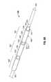
- FIGS. 4 through 7show a sequentially-illustrated, assembly of components forming an ablation device or probe, shown generally as 701 in FIG. 7 , in accordance with the present disclosure.
- a coaxial feedline 426is shown with the outer conductor 424 trimmed back, such that a portion 421 of the dielectric material 422 and the inner conductor 420 , having a length “L 7 ”, extends beyond the outer conductor 424 .
- an energy applicator segment shown generally as 400 in FIG. 4includes an electrically-conductive element 460 that extends along the longitudinal axis “A” of the inner conductor 420 .
- Electrically-conductive element 460may be positioned in a distal portion of the ablation device 701 .
- the electrically-conductive element 460is a solid metal cylinder disposed at the distal end of the portion 421 electrically coupled to the inner conductor 420 (e.g., by solder).
- Electrically-conductive element 460may be formed of any suitable electrically-conductive material (e.g., metal such as stainless steel, aluminum, titanium, copper, etc.) of any suitable length “L 8 ”. The shape and size of the electrically-conductive element 460 may be varied from the configuration depicted in FIG. 4 .
- FIG. 5shows an energy applicator segment 500 according to an embodiment of the present disclosure that is similar to the energy applicator segment 400 of FIG. 4 , except for a first dielectric layer 520 (also referred to herein as a balun insulator) disposed coaxially about a first portion 424 a of the outer conductor 424 and a second dielectric layer 530 disposed coaxially about a second portion 424 b of the outer conductor 424 .
- First balun insulator 520may have a suitable length “L 11 ” in a range from about 0.1 inches to about 3.0 inches.
- First balun insulator 520may be spaced apart from and disposed proximal to the distal end 425 of the outer conductor 424 .
- the distal end 521 of the first balun insulator 520is spaced apart, by a length “L 12 ”, e.g., about 0.1 inches, from the distal end 425 of the outer conductor 424 .
- Second balun insulator 530may have a suitable length “L 9 ” in a range from about 0.1 inches to about 3.0 inches.
- the distal end 531 of the second balun insulator 530may be disposed substantially adjacent to the proximal end 522 of the first balun insulator 520 . As shown in FIG. 5 , the distal end 531 of the second balun insulator 530 may be spaced apart, by a length “L 10 ”, from and disposed proximal to the proximal end 522 of the first balun insulator 520 .
- First and second balun insulators 520 , 530may be formed of any suitable insulative material, including, but not limited to, ceramics, water, mica, polyethylene, polyethylene terephthalate, polyimide, polytetrafluoroethylene (PTFE) (e.g., Teflon®, manufactured by E. I. du Pont de Nemours and Company of Wilmington, Del., United States), glass, metal oxides or other suitable insulator, and may be formed in any suitable manner.
- First and second dielectric layers 520 , 530may be grown, deposited or formed by any other suitable technique.
- the first dielectric layer 520is formed from a material with a dielectric constant in the range of about 1.7 to about 10.
- first balun insulator 520 and the second balun insulator 540may be varied from the configuration depicted in FIG. 5 .
- the first balun insulator 520may extend distally beyond the distal end of a conductive balun sleeve (e.g., 640 shown in FIG. 6A ) to direct current into a balancing/unbalancing (balun) structure (e.g., “B 1 ” shown in FIG. 6A ).
- balunbalancing/unbalancing
- FIG. 6Ashows an energy applicator segment 600 according to an embodiment of the present disclosure that is similar to the energy applicator segment 500 of FIG. 5 except for a first electrically-conductive layer 640 (also referred to herein as a conductive balun sleeve) disposed coaxially about the first balun insulator 520 and a second electrically-conductive layer 650 disposed coaxially about the second balun insulator 530 .
- the first electrically-conductive layer 640includes a proximal end 642 and a distal end 641
- the second electrically-conductive layer 650includes a proximal end 652 and a distal end 651 .
- First electrically-conductive layer 640may have any suitable length. In some embodiments, the first electrically-conductive layer 640 has a length of about 0.1 inches to about 3.0 inches. First electrically-conductive layer 640 may be formed as a single structure and electrically coupled to the outer conductor 424 , e.g., by solder or other suitable electrical connection. In some embodiments, the first electrically-conductive layer 640 includes a first portion 643 disposed coaxially about a proximal portion of the first balun insulator 520 , and a second portion 644 disposed proximally to the first portion 643 electrically coupled to the outer conductor 424 .
- First and second portions 643 , 644may be formed of any suitable electrically-conductive material, e.g., metal such as stainless steel, titanium, copper, etc., and may be formed in any suitable manner. First and second portions 643 , 644 may be formed separately from each other. First and second portions 643 , 644 may form a single, unitary structure. Second electrically-conductive layer 650 is similar to the first electrically-conductive layer 640 of FIG. 6A and further description thereof is omitted in the interests of brevity. The shape and size of the first electrically-conductive balun sleeve 640 and the second electrically-conductive balun sleeve 650 may be varied from the configuration depicted in FIG. 6A .
- FIG. 6Bshows an energy applicator segment 630 according to an embodiment of the present disclosure that is similar to the energy applicator segment 600 of FIG. 6A except for a third balun structure “B 3 ”.
- Third balun structure “B 3 ”is similar to the second balun structure “B 2 ” of FIG. 6A and further description thereof is omitted in the interests of brevity.
- the shape and size of the first balun structure “B 1 ”, the second balun structure “B 2 ”, and the third balun structure “B 3 ”may be varied from the configurations depicted in FIG. 6B .
- FIG. 7shows an ablation device 701 according to an embodiment of the present invention that includes an antenna assembly 712 disposed within a sheath 291 .
- Antenna assembly 712is similar to the energy applicator segment 600 shown in FIG. 6A , except for an outer dielectric layer 785 .
- Outer dielectric layer 785may configured to prevent direct contact between the coolant fluid “F” and the antenna assembly 712 .
- Outer dielectric layer 785in an embodiment, is a sleeve of fluorinated ethylene propylene (FEP) shrink wrap, and may be applied to the entire length of the antenna assembly 712 .
- the ablation device 701includes a tip 748 having a tapered end 724 that terminates at a pointed end 726 to allow for insertion into tissue with minimal resistance.
- a dipole feed gap “G”is defined between the proximal end of the electrically-conductive element 460 and the distal end (e.g., 425 shown in FIG. 5 ) of the outer conductor 424 .
- the feed gap “G”may be from about 1 mm to about 3 mm.
- the outer dielectric layer 785may be configured to cover the outer conductor 424 and the first balun insulator 520 and the first conductive balun sleeve 640 of first balun structure “B 1 ”.
- FIG. 10schematically illustrates an electrosurgical system 1000 according to an embodiment of the present disclosure including the ablation device or probe 101 . It will be understood, however, that other probe embodiments (e.g., 301 and 701 shown in FIGS. 3 and 7 , respectively) may also be used.
- Electrosurgical system 1000includes an actuator 20 operably coupled by a cable 19 via connector 17 to an embodiment of the generator assembly 28 of the electrosurgical system 10 of FIG. 1 .
- Actuator 20may be a footswitch, a handswitch, a bite-activated switch, or any other suitable actuator.
- Cable 19may include one or more electrical conductors for conveying an actuation signal from the actuator 20 to the generator assembly 28 .
- the actuator 20is operably coupled to the generator assembly 28 by a wireless link, such as without limitation, a radiofrequency or infrared link.
- the clinicianmay interact with the user interface 25 to preview operational characteristics of the ablation device 101 .
- Generator assembly 28includes a generator module (e.g., 86 shown in FIG. 11 ) in operable communication with a processor (e.g., 82 shown in FIG. 11 ), a user interface 25 , and an actuator 20 .
- Ablation device 101is operably coupled to an energy output of the generator module, which may be configured as a source of RF and/or microwave energy.
- Actuator 20is operably coupled to the processor via the user interface 25 .
- actuator 20may be operably coupled to the processor and/or to the generator module by a cable connection or a wireless connection.
- User interface 25may include a display 21 , such as without limitation a flat panel graphic LCD (liquid crystal display), adapted to visually display at least one user interface element 23 , 24 .
- display 21includes touchscreen capability (not shown), e.g., the ability to receive input from an object in physical contact with the display, such as without limitation, a stylus or a user's fingertip.
- a user interface element 23 , 24may have a corresponding active region, such that, by touching the screen within the active region associated with the user interface element, an input associated with the user interface element 23 , 24 is received by the user interface 25 .
- User interface 25may additionally, or alternatively, include one or more controls 22 that may include without limitation a switch (e.g., pushbutton switch, toggle switch, slide switch) and/or a continuous actuator (e.g., rotary or linear potentiometer, rotary or linear encoder).
- a control 22has a dedicated function, e.g., display contrast, power on/off, and the like. Control 22 may also have a function that may vary in accordance with an operational mode of the electrosurgical system 1000 .
- a user interface element 23may be positioned substantially adjacently to control 22 to indicate the function thereof.
- Control 22may also include an indicator, such as an illuminated indicator, e.g., a single- or variably-colored LED indicator.
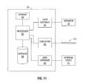
- FIG. 11is a block diagram showing one embodiment of the electrosurgical system 1000 of FIG. 10 .
- the generator module 86is configured to provide energy of about 915 MHz.
- Generator module 86may additionally, or alternatively, be configured to provide energy of about 2450 MHz (2.45 GHz) or about 5800 MHz (5.8 GHz).
- the present disclosurecontemplates embodiments wherein the generator module 86 is configured to generate a frequency other than about 915 MHz or about 2450 MHz or about 5800 MHz, and embodiments wherein the generator module 86 is configured to generate variable frequency energy.
- Generator assembly 28includes a processor 82 that is operably coupled to the user interface 25 .
- Processor 82may include any type of computing device, computational circuit, or any type of processor or processing circuit capable of executing a series of instructions that are stored in a memory, e.g., storage device 88 or external device 91 .
- a storage device 88is operably coupled to the processor 82 , and may include random-access memory (RAM), read-only memory (ROM), and/or non-volatile memory (NV-RAM, Flash, and disc-based storage.)
- Storage device 88may include a set of program instructions executable on the processor 82 for executing a method for displaying and controlling ablation patterns in accordance with the present disclosure.
- Generator assembly 86may include a data interface 90 that is configured to provide a communications link to an external device 91 .
- the data interface 90may be any of a USB interface, a memory card slot (e.g., SD slot), and/or a network interface (e.g., 100 BaseT Ethernet interface or an 802.11 “Wi-Fi” interface.)
- External device 91may be any of a USB device (e.g., a memory stick), a memory card (e.g., an SD card), and/or a network-connected device (e.g., computer or server).
- Generator assembly 28may also include a database 84 that is configured to store and retrieve energy applicator data, e.g., parameters associated with one or energy applicators (e.g., 101 shown in FIG. 11 ).
- Parameters stored in the database 84 in connection with an energy applicator, or energy applicator array assemblymay include, but are not limited to, energy applicator (or applicator array assembly) identifier, energy applicator (or applicator array assembly) dimensions, a frequency, an ablation length (e.g., in relation to a radiating section length), an ablation diameter, a gap distance at the feed point (e.g., in relation to an ablation geometry), a temporal coefficient, a shape metric, and/or a frequency metric.
- ablation pattern topologymay be included in the database 84 , e.g., a wireframe model of an applicator array assembly and/or an ablation pattern associated therewith.
- Database 84may also be maintained at least in part by data provided by the external device 91 via the data interface 90 .
- energy applicator datamay be uploaded from an external device 91 to the database 84 via the data interface 90 .
- Energy applicator datamay additionally, or alternatively, be manipulated, e.g., added, modified, or deleted, in accordance with data and/or instructions stored on the external device 91 .
- the set of energy applicator data represented in the database 84is automatically synchronized with corresponding data contained in the external device 91 in response to the external device 91 being coupled (e.g., physical coupling and/or logical coupling) to the data interface 90 .
- Processor 82is programmed to enable a user, via the user interface 25 and/or the display 21 , to view at least one ablation pattern and/or other energy applicator data corresponding to an embodiment of an applicator array assembly. For example, a surgeon may determine that a substantially spherical ablation pattern is necessary. The surgeon may activate a “select ablation shape” mode of operation for generator assembly 28 , preview an energy applicator array by reviewing graphically and textually presented data on the display 21 , optionally, or alternatively, manipulate a graphic image by, for example, rotating the image, and select an array of energy applicators based upon displayed parameters. The selected energy applicator(s) may then be electrically coupled to the generator assembly 28 for use therewith.
- a surgeonmay input via the user interface 25 an applicator array parameter to cause the generator assembly 28 to present one or more electromagnetic energy delivery devices corresponding thereto. For example, a surgeon may require a 3.0 cm ⁇ 3.0 cm ablation pattern, and provide an input corresponding thereto.
- the generator assembly 28may preview a corresponding subset of available electromagnetic energy delivery devices that match or correlate to the inputted parameter.
- Electrosurgical system 1000may include a feedback looping mechanism suitable for use in controlling an embodiment of an ablation device in accordance with the present disclosure.
- the feedback looping mechanismmay include, without limitation, proximity sensors, a voltage divider network, radial sensors, and/or feedback clicks, e.g., based upon the thread ratio of the threads 357 a , 358 a.
- FIG. 12is a flowchart illustrating a method of adjusting ablation volume according to an embodiment of the present disclosure.
- an ablation devicee.g., 701 shown in FIG. 7
- the ablation devicemay be inserted directly into tissue, inserted through a lumen, e.g., a vein, needle or catheter, placed into the body during surgery by a clinician, or positioned in the body by other suitable methods known in the art.
- the ablation deviceincludes an antenna assembly (e.g., 712 shown in FIG. 7 ) configured with a first balun (e.g., “B 1 ” shown in FIG.
- the ablation devicemay also include a third balun (e.g., “B 3 ” shown in FIG. 6B ) operably associated with a third operating frequency.
- step 1220energy is transmitted from an energy source (e.g., 28 shown in FIG. 1 ) through the antenna assembly (e.g., 712 shown in FIG. 7 ) to tissue at the first operating frequency.
- the first operating frequencymay be about 915 MHz.
- step 1230energy is transmitted from the energy source through the antenna assembly to tissue at the second operating frequency.
- the second operating frequencymay be about 2.45 GHz.
- ablation devices with dual operating frequencies and methods of adjusting ablation volumemay allow clinicians to avoid ablating or unnecessarily heating tissue structures, such as large vessels, healthy organs or vital membrane barriers, by adjusting the ablation volume.
- the above-described electrosurgical systems including the presently disclosed ablation devicesmay enable a user to view one or more ablation patterns and/or other energy applicator data corresponding to a particular ablation device, which may allow clinicians to predict ablation volume, avoid complications, and/or plan for treatment margins.
- the above-described electrosurgical systemsmay be adapted to automatically adjust the operating frequency of the presently disclosed ablation devices with dual operating frequencies, e.g., to adjust the ablation volume.
- the above-described ablation devicesmay be designed to operate at a first operating frequency of about 915 MHz, and a second operating frequency of about 2.45 GHz or about 5.8 GHz, or any other applicable frequencies.
- the presently disclosed ablation devicesinclude a first balun structure adapted to allow for operation at a first frequency and a second balun structure adapted to allow for operation at a second frequency, and electrosurgical systems including the same may be operated at a first frequency, e.g., about 915 MHz, wherein the distal radiating section has a first length, e.g., about 4 cm, and a second frequency, e.g., about 2.45 GHz, wherein the distal radiating section is adjusted to have a second length, e.g., about 2 cm.
- the second balun structuremay be adapted to allow for operation at a second frequency of about 5.8 GHz, wherein the distal radiating section is adjusted to have a length of about 1 cm.
- the presently disclosed ablation devicesinclude a first balun structure adapted to allow for operation at a first frequency (e.g., about 915 MHz), a second balun structure adapted to allow for operation at a second frequency (e.g., about 2.45 GHz) and a third balun structure adapted to allow for operation at a third frequency (e.g., about 5.8 GHz).
- a first frequencye.g., about 915 MHz
- a second balun structureadapted to allow for operation at a second frequency
- a third balun structureadapted to allow for operation at a third frequency (e.g., about 5.8 GHz).
Landscapes
- Health & Medical Sciences (AREA)
- Surgery (AREA)
- Life Sciences & Earth Sciences (AREA)
- Engineering & Computer Science (AREA)
- Biomedical Technology (AREA)
- Molecular Biology (AREA)
- Nuclear Medicine, Radiotherapy & Molecular Imaging (AREA)
- Veterinary Medicine (AREA)
- Physics & Mathematics (AREA)
- Heart & Thoracic Surgery (AREA)
- Medical Informatics (AREA)
- Otolaryngology (AREA)
- Animal Behavior & Ethology (AREA)
- General Health & Medical Sciences (AREA)
- Public Health (AREA)
- Electromagnetism (AREA)
- Plasma & Fusion (AREA)
- Surgical Instruments (AREA)
- Radiation-Therapy Devices (AREA)
Abstract
Description
where σ is the tissue electrical conductivity in units of Siemens per meter (S/m), ρ is the tissue density in units of kilograms per cubic meter (kg/m3), and |E| is the magnitude of the local electric field in units of volts per meter (V/m).
where c is the specific heat of the tissue (in units of Joules/kg-° C.), and Δt is the time period of exposure in seconds (sec). Substituting equation (1) into equation (2) yields a relation between the induced temperature rise in tissue and the applied electric field as
Claims (18)
Priority Applications (7)
| Application Number | Priority Date | Filing Date | Title |
|---|---|---|---|
| US12/709,014US8968288B2 (en) | 2010-02-19 | 2010-02-19 | Ablation devices with dual operating frequencies, systems including same, and methods of adjusting ablation volume using same |
| EP17186390.5AEP3281597B1 (en) | 2010-02-19 | 2011-02-14 | Ablation devices with dual operating frequencies |
| EP11001182.2AEP2361582B1 (en) | 2010-02-19 | 2011-02-14 | Ablation devices with dual operating frequencies and systems including same. |
| JP2011029431AJP6047274B2 (en) | 2010-02-19 | 2011-02-15 | Ablation device having dual operating frequency, system including the same, and method for adjusting the ablation volume using the device |
| US14/629,983US9724159B2 (en) | 2010-02-19 | 2015-02-24 | Ablation devices with dual operating frequencies, systems including same, and methods of adjusting ablation volume using same |
| US15/667,745US10987152B2 (en) | 2010-02-19 | 2017-08-03 | Ablation devices with dual operating frequencies, systems including same, and methods of adjusting ablation volume using same |
| US17/238,309US20210259757A1 (en) | 2010-02-19 | 2021-04-23 | Ablation devices with dual operating frequencies, systems including same, and methods of adjusting ablation volume using same |
Applications Claiming Priority (1)
| Application Number | Priority Date | Filing Date | Title |
|---|---|---|---|
| US12/709,014US8968288B2 (en) | 2010-02-19 | 2010-02-19 | Ablation devices with dual operating frequencies, systems including same, and methods of adjusting ablation volume using same |
Related Child Applications (1)
| Application Number | Title | Priority Date | Filing Date |
|---|---|---|---|
| US14/629,983ContinuationUS9724159B2 (en) | 2010-02-19 | 2015-02-24 | Ablation devices with dual operating frequencies, systems including same, and methods of adjusting ablation volume using same |
Publications (2)
| Publication Number | Publication Date |
|---|---|
| US20110208177A1 US20110208177A1 (en) | 2011-08-25 |
| US8968288B2true US8968288B2 (en) | 2015-03-03 |
Family
ID=44083589
Family Applications (4)
| Application Number | Title | Priority Date | Filing Date |
|---|---|---|---|
| US12/709,014Active2031-10-17US8968288B2 (en) | 2010-02-19 | 2010-02-19 | Ablation devices with dual operating frequencies, systems including same, and methods of adjusting ablation volume using same |
| US14/629,983Expired - Fee RelatedUS9724159B2 (en) | 2010-02-19 | 2015-02-24 | Ablation devices with dual operating frequencies, systems including same, and methods of adjusting ablation volume using same |
| US15/667,745Expired - Fee RelatedUS10987152B2 (en) | 2010-02-19 | 2017-08-03 | Ablation devices with dual operating frequencies, systems including same, and methods of adjusting ablation volume using same |
| US17/238,309AbandonedUS20210259757A1 (en) | 2010-02-19 | 2021-04-23 | Ablation devices with dual operating frequencies, systems including same, and methods of adjusting ablation volume using same |
Family Applications After (3)
| Application Number | Title | Priority Date | Filing Date |
|---|---|---|---|
| US14/629,983Expired - Fee RelatedUS9724159B2 (en) | 2010-02-19 | 2015-02-24 | Ablation devices with dual operating frequencies, systems including same, and methods of adjusting ablation volume using same |
| US15/667,745Expired - Fee RelatedUS10987152B2 (en) | 2010-02-19 | 2017-08-03 | Ablation devices with dual operating frequencies, systems including same, and methods of adjusting ablation volume using same |
| US17/238,309AbandonedUS20210259757A1 (en) | 2010-02-19 | 2021-04-23 | Ablation devices with dual operating frequencies, systems including same, and methods of adjusting ablation volume using same |
Country Status (3)
| Country | Link |
|---|---|
| US (4) | US8968288B2 (en) |
| EP (2) | EP3281597B1 (en) |
| JP (1) | JP6047274B2 (en) |
Cited By (23)
| Publication number | Priority date | Publication date | Assignee | Title |
|---|---|---|---|---|
| US9241762B2 (en) | 2010-06-03 | 2016-01-26 | Covidien Lp | Specific absorption rate measurement and energy-delivery device characterization using image analysis |
| US9724151B2 (en) | 2013-08-08 | 2017-08-08 | Relievant Medsystems, Inc. | Modulating nerves within bone using bone fasteners |
| US9724159B2 (en) | 2010-02-19 | 2017-08-08 | Covidien Lp | Ablation devices with dual operating frequencies, systems including same, and methods of adjusting ablation volume using same |
| US9743985B2 (en) | 2010-12-23 | 2017-08-29 | Covidien Lp | Microwave field-detecting needle assemblies, methods of manufacturing same, methods of adjusting an ablation field radiating into tissue using same, and systems including same |
| US9775627B2 (en) | 2012-11-05 | 2017-10-03 | Relievant Medsystems, Inc. | Systems and methods for creating curved paths through bone and modulating nerves within the bone |
| US20180049805A1 (en)* | 2007-05-22 | 2018-02-22 | Covidien Lp | Energy delivery conduits for use with electrosurgical devices |
| US10028753B2 (en) | 2008-09-26 | 2018-07-24 | Relievant Medsystems, Inc. | Spine treatment kits |
| US10111704B2 (en) | 2002-09-30 | 2018-10-30 | Relievant Medsystems, Inc. | Intraosseous nerve treatment |
| US10251701B2 (en) | 2010-05-25 | 2019-04-09 | Covidien Lp | Flow rate verification monitor for fluid-cooled microwave ablation probe |
| US10265099B2 (en) | 2008-09-26 | 2019-04-23 | Relievant Medsystems, Inc. | Systems for accessing nerves within bone |
| US10390877B2 (en) | 2011-12-30 | 2019-08-27 | Relievant Medsystems, Inc. | Systems and methods for treating back pain |
| US10448996B2 (en) | 2011-12-29 | 2019-10-22 | Koninklijke Philips N.V. | Electrosurgical ablation apparatus |
| US10463423B2 (en) | 2003-03-28 | 2019-11-05 | Relievant Medsystems, Inc. | Thermal denervation devices and methods |
| US10588691B2 (en) | 2012-09-12 | 2020-03-17 | Relievant Medsystems, Inc. | Radiofrequency ablation of tissue within a vertebral body |
| US10588684B2 (en) | 2010-07-19 | 2020-03-17 | Covidien Lp | Hydraulic conductivity monitoring to initiate tissue division |
| USRE48460E1 (en) | 2002-09-30 | 2021-03-09 | Relievant Medsystems, Inc. | Method of treating an intraosseous nerve |
| US11007010B2 (en) | 2019-09-12 | 2021-05-18 | Relevant Medsysterns, Inc. | Curved bone access systems |
| US11058488B2 (en) | 2011-01-05 | 2021-07-13 | Covidien Lp | Energy-delivery devices with flexible fluid-cooled shaft, inflow / outflow junctions suitable for use with same, and systems including same |
| US11147622B2 (en) | 2011-03-09 | 2021-10-19 | Covidien Lp | Systems for thermal-feedback-controlled rate of fluid flow to fluid-cooled antenna assembly and methods of directing energy to tissue using same |
| US11432870B2 (en) | 2016-10-04 | 2022-09-06 | Avent, Inc. | Cooled RF probes |
| US12039731B2 (en) | 2020-12-22 | 2024-07-16 | Relievant Medsystems, Inc. | Prediction of candidates for spinal neuromodulation |
| US12082876B1 (en) | 2020-09-28 | 2024-09-10 | Relievant Medsystems, Inc. | Introducer drill |
| US12433668B1 (en) | 2021-11-08 | 2025-10-07 | Relievant Medsystems, Inc. | Impedance stoppage mitigation during radiofrequency tissue ablation procedures |
Families Citing this family (37)
| Publication number | Priority date | Publication date | Assignee | Title |
|---|---|---|---|---|
| US7553309B2 (en) | 2004-10-08 | 2009-06-30 | Covidien Ag | Electrosurgical system employing multiple electrodes and method thereof |
| GB2452103B (en) | 2007-01-05 | 2011-08-31 | Arthrocare Corp | Electrosurgical system with suction control apparatus and system |
| US7951144B2 (en) | 2007-01-19 | 2011-05-31 | Mahajan Roop L | Thermal and electrical conductivity probes and methods of making the same |
| US8211099B2 (en) | 2007-01-31 | 2012-07-03 | Tyco Healthcare Group Lp | Thermal feedback systems and methods of using the same |
| GB0718721D0 (en) | 2007-09-25 | 2007-11-07 | Medical Device Innovations Ltd | Surgical resection apparatus |
| US9358063B2 (en) | 2008-02-14 | 2016-06-07 | Arthrocare Corporation | Ablation performance indicator for electrosurgical devices |
| US8292881B2 (en) | 2009-05-27 | 2012-10-23 | Vivant Medical, Inc. | Narrow gauge high strength choked wet tip microwave ablation antenna |
| US8394087B2 (en) | 2009-09-24 | 2013-03-12 | Vivant Medical, Inc. | Optical detection of interrupted fluid flow to ablation probe |
| US8372067B2 (en) | 2009-12-09 | 2013-02-12 | Arthrocare Corporation | Electrosurgery irrigation primer systems and methods |
| US8728067B2 (en) | 2010-03-08 | 2014-05-20 | Covidien Lp | Microwave antenna probe having a deployable ground plane |
| US9561076B2 (en)* | 2010-05-11 | 2017-02-07 | Covidien Lp | Electrosurgical devices with balun structure for air exposure of antenna radiating section and method of directing energy to tissue using same |
| US8652127B2 (en) | 2010-05-26 | 2014-02-18 | Covidien Lp | System and method for chemically cooling an ablation antenna |
| US8672933B2 (en) | 2010-06-30 | 2014-03-18 | Covidien Lp | Microwave antenna having a reactively-loaded loop configuration |
| US8685018B2 (en) | 2010-10-15 | 2014-04-01 | Arthrocare Corporation | Electrosurgical wand and related method and system |
| US9011421B2 (en) | 2011-01-05 | 2015-04-21 | Covidien Lp | Energy-delivery devices with flexible fluid-cooled shaft, inflow/outflow junctions suitable for use with same, and systems including same |
| US9017319B2 (en)* | 2011-01-05 | 2015-04-28 | Covidien Lp | Energy-delivery devices with flexible fluid-cooled shaft, inflow/outflow junctions suitable for use with same, and systems including same |
| US9131597B2 (en) | 2011-02-02 | 2015-09-08 | Arthrocare Corporation | Electrosurgical system and method for treating hard body tissue |
| US9028476B2 (en) | 2011-02-03 | 2015-05-12 | Covidien Lp | Dual antenna microwave resection and ablation device, system and method of use |
| US9095360B2 (en)* | 2012-04-06 | 2015-08-04 | Wisconsin Alumni Research Foundation | Feeding structure for dual slot microwave ablation probe |
| US9993295B2 (en)* | 2012-08-07 | 2018-06-12 | Covidien Lp | Microwave ablation catheter and method of utilizing the same |
| JP6574706B2 (en) | 2013-03-07 | 2019-09-11 | アースロケア コーポレイション | Electrosurgical system and method |
| US9693818B2 (en) | 2013-03-07 | 2017-07-04 | Arthrocare Corporation | Methods and systems related to electrosurgical wands |
| US9801678B2 (en) | 2013-03-13 | 2017-10-31 | Arthrocare Corporation | Method and system of controlling conductive fluid flow during an electrosurgical procedure |
| US10420607B2 (en) | 2014-02-14 | 2019-09-24 | Arthrocare Corporation | Methods and systems related to an electrosurgical controller |
| US10765477B2 (en)* | 2014-03-10 | 2020-09-08 | Wisconsin Alumni Research Foundation | Microwave ablation antenna system |
| US10624697B2 (en)* | 2014-08-26 | 2020-04-21 | Covidien Lp | Microwave ablation system |
| GB2550537B (en)* | 2016-02-11 | 2018-04-04 | Gyrus Medical Ltd | Microwave ablation antenna assemblies |
| US10456156B2 (en)* | 2016-03-29 | 2019-10-29 | Covidien Lp | Devices, systems, and methods for cooling a surgical instrument |
| CN106420048A (en)* | 2016-08-31 | 2017-02-22 | 赛诺微医疗科技(北京)有限公司 | Flexible microwave ablation antenna and microwave ablation needle using same |
| GB2560973A (en)* | 2017-03-30 | 2018-10-03 | Creo Medical Ltd | Electrosurgical instrument |
| US10707581B2 (en) | 2018-01-03 | 2020-07-07 | Wisconsin Alumni Research Foundation | Dipole antenna for microwave ablation |
| CN108523990B (en)* | 2018-01-30 | 2020-08-07 | 青岛大学附属医院 | A microwave ablation apparatus for treating uterine fibroids |
| ES2916523T3 (en)* | 2018-05-31 | 2022-07-01 | Bh Scient Llc | System for microwave ablation and temperature measurement during ablation |
| CN109199582B (en)* | 2018-10-30 | 2020-11-20 | 赛诺微医疗科技(浙江)有限公司 | Wide-range microwave ablation antenna and lung microwave ablation soft electrode adopting same |
| WO2022051654A1 (en)* | 2020-09-03 | 2022-03-10 | Kansas State University Research Foundation | Microwave catheters for high-power thermal ablation |
| GB202210323D0 (en)* | 2022-07-14 | 2022-08-31 | Creo Medical Ltd | Electrosurgical instrument for conveying and emitting microwave electromagnetic energy into biological tissue for tissue treatment |
| US12390278B2 (en) | 2023-10-31 | 2025-08-19 | Hepta Medical SAS | Systems and methods for adaptive ablation volume prediction based on tissue temperature measurements and anatomical segmentation |
Citations (106)
| Publication number | Priority date | Publication date | Assignee | Title |
|---|---|---|---|---|
| DE390937C (en) | 1922-10-13 | 1924-03-03 | Adolf Erb | Device for internal heating of furnace furnaces for hardening, tempering, annealing, quenching and melting |
| DE1099658B (en) | 1959-04-29 | 1961-02-16 | Siemens Reiniger Werke Ag | Automatic switch-on device for high-frequency surgical devices |
| FR1275415A (en) | 1960-09-26 | 1961-11-10 | Device for detecting disturbances for electrical installations, in particular electrosurgery | |
| DE1139927B (en) | 1961-01-03 | 1962-11-22 | Friedrich Laber | High-frequency surgical device |
| DE1149832B (en) | 1961-02-25 | 1963-06-06 | Siemens Reiniger Werke Ag | High frequency surgical apparatus |
| FR1347865A (en) | 1962-11-22 | 1964-01-04 | Improvements to diathermo-coagulation devices | |
| DE1439302A1 (en) | 1963-10-26 | 1969-01-23 | Siemens Ag | High-frequency surgical device |
| SU401367A1 (en) | 1971-10-05 | 1973-10-12 | Тернопольский государственный медицинский институт | BIAKTIVNYE ELECTRO SURGICAL INSTRUMENT |
| FR2235669A1 (en) | 1973-07-07 | 1975-01-31 | Lunacek Boris | Gynaecological sterilisation instrument - has hollow electrode protruding from the end of a curved ended tube |
| DE2439587A1 (en) | 1973-08-23 | 1975-02-27 | Matburn Holdings Ltd | ELECTROSURGICAL DEVICE |
| DE2455174A1 (en) | 1973-11-21 | 1975-05-22 | Termiflex Corp | INPUT / OUTPUT DEVICE FOR DATA EXCHANGE WITH DATA PROCESSING DEVICES |
| DE2407559A1 (en) | 1974-02-16 | 1975-08-28 | Dornier System Gmbh | Tissue heat treatment probe - has water cooling system which ensures heat development only in treated tissues |
| DE2415263A1 (en) | 1974-03-29 | 1975-10-02 | Aesculap Werke Ag | Surgical H.F. coagulation probe has electrode tongs - with exposed ends of insulated conductors forming tong-jaws |
| DE2429021A1 (en) | 1974-06-18 | 1976-01-08 | Erbe Elektromedizin | Remote control for HF surgical instruments - uses cable with two conductors at most |
| FR2276027A1 (en) | 1974-06-25 | 1976-01-23 | Medical Plastics Inc | Plate electrode with connector - is clamped between connector jaws held by releasable locking device |
| DE2460481A1 (en) | 1974-12-20 | 1976-06-24 | Delma Elektro Med App | Electrode grip for remote HF surgical instrument switching - has shaped insulated piece with contact ring of sterilizable (silicon) rubber |
| DE2602517A1 (en) | 1975-01-23 | 1976-07-29 | Dentsply Int Inc | ELECTROSURGICAL DEVICE |
| DE2504280A1 (en) | 1975-02-01 | 1976-08-05 | Hans Heinrich Prof Dr Meinke | DEVICE FOR ELECTRIC TISSUE CUTTING IN SURGERY |
| FR2313708A1 (en) | 1975-06-02 | 1976-12-31 | Sybron Corp | Electro surgical instrument impulse control circuit - has potentiometer between patient electrodes and threshold switch for excessive voltage |
| DE2627679A1 (en) | 1975-06-26 | 1977-01-13 | Marcel Lamidey | HEMATISTIC HIGH FREQUENCY EXTRACTOR FORCEPS |
| DE2540968A1 (en) | 1975-09-13 | 1977-03-17 | Erbe Elektromedizin | Circuit for bipolar coagulation tweezers - permits preparation of tissues prior to coagulation |
| DE2820908A1 (en) | 1977-05-16 | 1978-11-23 | Joseph Skovajsa | DEVICE FOR THE LOCAL TREATMENT OF A PATIENT IN PARTICULAR FOR ACUPUNCTURE OR AURICULAR THERAPY |
| DE2803275A1 (en) | 1978-01-26 | 1979-08-02 | Aesculap Werke Ag | HF surgical appts. with active treatment and patient electrodes - has sensor switching generator to small voltage when hand-operated switch is closed |
| DE2823291A1 (en) | 1978-05-27 | 1979-11-29 | Rainer Ing Grad Koch | Coagulation instrument automatic HF switching circuit - has first lead to potentiometer and second to transistor base |
| SU727201A2 (en) | 1977-11-02 | 1980-04-15 | Киевский Научно-Исследовательский Институт Нейрохирургии | Electric surgical apparatus |
| DE2946728A1 (en) | 1979-11-20 | 1981-05-27 | Erbe Elektromedizin GmbH & Co KG, 7400 Tübingen | HF surgical appts. for use with endoscope - provides cutting or coagulation current at preset intervals and of selected duration |
| USD263020S (en) | 1980-01-22 | 1982-02-16 | Rau Iii David M | Retractable knife |
| DE3143421A1 (en) | 1980-11-04 | 1982-05-27 | The Agency of Industrial Science and Technology, Tokyo | Laser scalpel |
| DE3045996A1 (en) | 1980-12-05 | 1982-07-08 | Medic Eschmann Handelsgesellschaft für medizinische Instrumente mbH, 2000 Hamburg | Electro-surgical scalpel instrument - has power supply remotely controlled by surgeon |
| FR2502935A1 (en) | 1981-03-31 | 1982-10-08 | Dolley Roger | Diathermic knife for coagulating tissues - has monitoring current added to HF coagulating current in order to control end of operation as function or resistance of coagulating tissues |
| DE3120102A1 (en) | 1981-05-20 | 1982-12-09 | F.L. Fischer GmbH & Co, 7800 Freiburg | ARRANGEMENT FOR HIGH-FREQUENCY COAGULATION OF EGG WHITE FOR SURGICAL PURPOSES |
| FR2517953A1 (en) | 1981-12-10 | 1983-06-17 | Alvar Electronic | Diaphanometer for optical examination of breast tissue structure - measures tissue transparency using two plates and optical fibre bundle cooperating with photoelectric cells |
| FR2573301A1 (en) | 1984-11-16 | 1986-05-23 | Lamidey Gilles | Surgical forceps and its control and monitoring apparatus |
| DE3510586A1 (en) | 1985-03-23 | 1986-10-02 | Erbe Elektromedizin GmbH, 7400 Tübingen | Control device for a high-frequency surgical instrument |
| DE3604823A1 (en) | 1986-02-15 | 1987-08-27 | Flachenecker Gerhard | HIGH FREQUENCY GENERATOR WITH AUTOMATIC PERFORMANCE CONTROL FOR HIGH FREQUENCY SURGERY |
| EP0246350A1 (en) | 1986-05-23 | 1987-11-25 | Erbe Elektromedizin GmbH. | Coagulation electrode |
| DE8712328U1 (en) | 1987-09-11 | 1988-02-18 | Jakoubek, Franz, 7201 Emmingen-Liptingen | Endoscopy forceps |
| USD295894S (en) | 1985-09-26 | 1988-05-24 | Acme United Corporation | Disposable surgical scissors |
| USD295893S (en) | 1985-09-25 | 1988-05-24 | Acme United Corporation | Disposable surgical clamp |
| DE3711511C1 (en) | 1987-04-04 | 1988-06-30 | Hartmann & Braun Ag | Method for determining gas concentrations in a gas mixture and sensor for measuring thermal conductivity |
| DE3904558A1 (en) | 1989-02-15 | 1990-08-23 | Flachenecker Gerhard | Radio-frequency generator with automatic power control for radio-frequency surgery |
| DE3942998A1 (en) | 1989-12-27 | 1991-07-04 | Delma Elektro Med App | Electro-surgical HF instrument for contact coagulation - has monitoring circuit evaluating HF voltage at electrodes and delivering switch=off signal |
| EP0521264A2 (en) | 1991-07-03 | 1993-01-07 | W.L. Gore & Associates GmbH | Antenna device with feed |
| JPH055106A (en) | 1990-07-31 | 1993-01-14 | Matsushita Electric Works Ltd | Production of alloy sintered body |
| JPH0540112A (en) | 1991-02-08 | 1993-02-19 | Tokico Ltd | Sample liquid component analyzer |
| DE4238263A1 (en) | 1991-11-15 | 1993-05-19 | Minnesota Mining & Mfg | Adhesive comprising hydrogel and crosslinked polyvinyl:lactam - is used in electrodes for biomedical application providing low impedance and good mechanical properties when water and/or moisture is absorbed from skin |
| EP0556705A1 (en) | 1992-02-20 | 1993-08-25 | DELMA ELEKTRO-UND MEDIZINISCHE APPARATEBAU GESELLSCHAFT mbH | High frequency surgery device |
| EP0558429A1 (en) | 1992-02-26 | 1993-09-01 | PECHINEY RECHERCHE (Groupement d'Intérêt Economique géré par l'ordonnance no. 67-821 du 23 Septembre 1967) | Method of simultaneous measuring of electrical resistivety and thermal conductivity |
| US5300068A (en) | 1992-04-21 | 1994-04-05 | St. Jude Medical, Inc. | Electrosurgical apparatus |
| US5301687A (en)* | 1991-06-06 | 1994-04-12 | Trustees Of Dartmouth College | Microwave applicator for transurethral hyperthermia |
| DE4303882A1 (en) | 1993-02-10 | 1994-08-18 | Kernforschungsz Karlsruhe | Combined instrument for separating and coagulating in minimally invasive surgery |
| JPH06343644A (en) | 1993-05-04 | 1994-12-20 | Gyrus Medical Ltd | Surgical peritoneoscope equipment |
| DE4339049A1 (en) | 1993-11-16 | 1995-05-18 | Erbe Elektromedizin | Surgical system and instruments configuration device |
| JPH07265328A (en) | 1993-11-01 | 1995-10-17 | Gyrus Medical Ltd | Electrode assembly for electric surgery device and electric surgery device using it |
| JPH0856955A (en) | 1994-06-29 | 1996-03-05 | Gyrus Medical Ltd | Electric surgical apparatus |
| JPH08252263A (en) | 1994-12-21 | 1996-10-01 | Gyrus Medical Ltd | Electronic surgical incision instrument and electronic surgical incision device using the same |
| DE29616210U1 (en) | 1996-09-18 | 1996-11-14 | Olympus Winter & Ibe Gmbh, 22045 Hamburg | Handle for surgical instruments |
| JPH0910223A (en) | 1995-06-23 | 1997-01-14 | Gyrus Medical Ltd | Generator and system for electric operation |
| DE19608716C1 (en) | 1996-03-06 | 1997-04-17 | Aesculap Ag | Bipolar surgical holding instrument |
| EP0836868A2 (en) | 1996-10-18 | 1998-04-22 | Gebr. Berchtold GmbH & Co. | High frequency surgical apparatus and method for operating same |
| DE19751106A1 (en) | 1996-11-27 | 1998-05-28 | Eastman Kodak Co | Laser printer with array of laser diodes |
| DE19717411A1 (en) | 1997-04-25 | 1998-11-05 | Aesculap Ag & Co Kg | Monitoring of thermal loading of patient tissue in contact region of neutral electrode of HF treatment unit |
| EP0882955A1 (en) | 1997-06-06 | 1998-12-09 | Endress + Hauser GmbH + Co. | Level measuring apparatus using microwaves |
| US5871525A (en)* | 1992-04-13 | 1999-02-16 | Ep Technologies, Inc. | Steerable ablation catheter system |
| DE19751108A1 (en) | 1997-11-18 | 1999-05-20 | Beger Frank Michael Dipl Desig | Electrosurgical operation tool, especially for diathermy |
| DE19801173C1 (en) | 1998-01-15 | 1999-07-15 | Kendall Med Erzeugnisse Gmbh | Clamp connector for film electrodes |
| JPH11244298A (en) | 1997-12-19 | 1999-09-14 | Gyrus Medical Ltd | Electric surgical instrument |
| US5957969A (en)* | 1993-05-14 | 1999-09-28 | Fidus Medical Technology Corporation | Tunable microwave ablation catheter system and method |
| US6016452A (en) | 1996-03-19 | 2000-01-18 | Kasevich; Raymond S. | Dynamic heating method and radio frequency thermal treatment |
| USD424694S (en) | 1998-10-23 | 2000-05-09 | Sherwood Services Ag | Forceps |
| USD425201S (en) | 1998-10-23 | 2000-05-16 | Sherwood Services Ag | Disposable electrode assembly |
| DE19848540A1 (en) | 1998-10-21 | 2000-05-25 | Reinhard Kalfhaus | Circuit layout and method for operating a single- or multiphase current inverter connects an AC voltage output to a primary winding and current and a working resistance to a transformer's secondary winding and current. |
| EP1034748A1 (en) | 1999-03-05 | 2000-09-13 | Gyrus Medical Limited | UHF electrosurgery system |
| EP1055400A1 (en) | 1999-05-28 | 2000-11-29 | Gyrus Medical Limited | An electrosurgical instrument |
| JP2000342599A (en) | 1999-05-21 | 2000-12-12 | Gyrus Medical Ltd | Generator for electrosurgical operation, electrosurgical operation system, method for operating this system and method for performing amputation and resection of tissue by electrosurgical operation |
| JP2000350732A (en) | 1999-05-21 | 2000-12-19 | Gyrus Medical Ltd | Electrosurgical system, generator for electrosurgery, and method for cutting or excising tissue by electrosurgery |
| JP2001008944A (en) | 1999-05-28 | 2001-01-16 | Gyrus Medical Ltd | Electric surgical signal generator and electric surgical system |
| JP2001029356A (en) | 1999-06-11 | 2001-02-06 | Gyrus Medical Ltd | Electric and surgical signal generator |
| USD449886S1 (en) | 1998-10-23 | 2001-10-30 | Sherwood Services Ag | Forceps with disposable electrode |
| EP1159926A2 (en) | 2000-06-03 | 2001-12-05 | Aesculap Ag | Scissor- or forceps-like surgical instrument |
| US20020022836A1 (en) | 1999-03-05 | 2002-02-21 | Gyrus Medical Limited | Electrosurgery system |
| USD457958S1 (en) | 2001-04-06 | 2002-05-28 | Sherwood Services Ag | Vessel sealer and divider |
| USD457959S1 (en) | 2001-04-06 | 2002-05-28 | Sherwood Services Ag | Vessel sealer |
| US6398781B1 (en) | 1999-03-05 | 2002-06-04 | Gyrus Medical Limited | Electrosurgery system |
| US6582427B1 (en) | 1999-03-05 | 2003-06-24 | Gyrus Medical Limited | Electrosurgery system |
| DE10224154A1 (en) | 2002-05-27 | 2003-12-18 | Celon Ag Medical Instruments | Application device for electrosurgical device for body tissue removal via of HF current has electrode subset selected from active electrode set in dependence on measured impedance of body tissue |
| WO2004047659A3 (en) | 2002-11-27 | 2004-07-29 | Christopher Paul Hancock | Tissue ablation apparatus and method of ablating tissue |
| USD496997S1 (en) | 2003-05-15 | 2004-10-05 | Sherwood Services Ag | Vessel sealer and divider |
| USD499181S1 (en) | 2003-05-15 | 2004-11-30 | Sherwood Services Ag | Handle for a vessel sealer and divider |
| US20050015081A1 (en)* | 2003-07-18 | 2005-01-20 | Roman Turovskiy | Devices and methods for cooling microwave antennas |
| DE10328514B3 (en) | 2003-06-20 | 2005-03-03 | Aesculap Ag & Co. Kg | Endoscopic surgical scissor instrument has internal pushrod terminating at distal end in transverse cylindrical head |
| US20050085881A1 (en)* | 2001-11-02 | 2005-04-21 | Vivant Medical, Inc. | High-strength microwave antenna assemblies |
| FR2862813A1 (en) | 2003-11-20 | 2005-05-27 | Pellenc Sa | METHOD FOR BALANCED LOADING OF LITHIUM-ION OR POLYMER LITHIUM BATTERY |
| FR2864439A1 (en) | 2003-12-30 | 2005-07-01 | Image Guided Therapy | Tumor treating device for use by surgeon, has generator applying voltage to each of active electrodes in manner independent from other electrodes and having sinusoidal voltage generation unit adjusting amplitude and phase of voltage |
| DE102004022206A1 (en) | 2004-05-04 | 2005-12-01 | Bundesrepublik Deutschland, vertr. d. d. Bundesministerium für Wirtschaft und Arbeit, dieses vertr. d. d. Präsidenten der Physikalisch-Technischen Bundesanstalt | Sensor for measuring thermal conductivity comprises a strip composed of two parallel sections, and two outer heating strips |
| DE202005015147U1 (en) | 2005-09-26 | 2006-02-09 | Health & Life Co., Ltd., Chung-Ho | Biosensor test strip with identifying function for biological measuring instruments has functioning electrode and counter electrode, identification zones with coating of electrically conductive material and reaction zone |
| USD525361S1 (en) | 2004-10-06 | 2006-07-18 | Sherwood Services Ag | Hemostat style elongated dissecting and dividing instrument |
| USD531311S1 (en) | 2004-10-06 | 2006-10-31 | Sherwood Services Ag | Pistol grip style elongated dissecting and dividing instrument |
| USD533942S1 (en) | 2004-06-30 | 2006-12-19 | Sherwood Services Ag | Open vessel sealer with mechanical cutter |
| USD535027S1 (en) | 2004-10-06 | 2007-01-09 | Sherwood Services Ag | Low profile vessel sealing and cutting mechanism |
| USD541418S1 (en) | 2004-10-06 | 2007-04-24 | Sherwood Services Ag | Lung sealing device |
| USD541938S1 (en) | 2004-04-09 | 2007-05-01 | Sherwood Services Ag | Open vessel sealer with mechanical cutter |
| US20080033497A1 (en)* | 2005-11-04 | 2008-02-07 | Cherik Bulkes | Mri compatible implanted electronic medical device and lead |
| USD564662S1 (en) | 2004-10-13 | 2008-03-18 | Sherwood Services Ag | Hourglass-shaped knife for electrosurgical forceps |
| JP2008142467A (en) | 2006-12-13 | 2008-06-26 | Murata Mfg Co Ltd | Coaxial probe |
| EP2008604A2 (en) | 2007-06-28 | 2008-12-31 | Vivant Medical, Inc. | Broadband microwave applicator |
Family Cites Families (62)
| Publication number | Priority date | Publication date | Assignee | Title |
|---|---|---|---|---|
| JPS55106B1 (en) | 1975-04-03 | 1980-01-05 | ||
| JPH0540112Y2 (en) | 1987-03-03 | 1993-10-12 | ||
| WO1989011311A1 (en)* | 1988-05-18 | 1989-11-30 | Kasevich Associates, Inc. | Microwave balloon angioplasty |
| ITPI20010006A1 (en)* | 2001-01-31 | 2002-07-31 | Cnr Consiglio Naz Delle Ricer | INTERSTITIAL ANTENNA WITH MINIATURIZED CHOKE FOR MICROWAVE HYPERTEMIA APPLICATIONS IN MEDICINE AND SURGERY |
| JP2006261801A (en)* | 2005-03-15 | 2006-09-28 | Ricoh Co Ltd | Multi-band microstrip antenna and module and system using the same |
| US7799019B2 (en)* | 2005-05-10 | 2010-09-21 | Vivant Medical, Inc. | Reinforced high strength microwave antenna |
| WO2008043999A2 (en)* | 2006-10-10 | 2008-04-17 | Medical Device Innovations Limited | Apparatus for treating tissue with microwave radiation and antenna calibration system and method |
| GB0620058D0 (en)* | 2006-10-10 | 2006-11-22 | Medical Device Innovations Ltd | Tissue measurement and ablation antenna |
| US8945111B2 (en) | 2008-01-23 | 2015-02-03 | Covidien Lp | Choked dielectric loaded tip dipole microwave antenna |
| US8965536B2 (en)* | 2008-03-03 | 2015-02-24 | Covidien Lp | Intracooled percutaneous microwave ablation probe |
| US20100045559A1 (en)* | 2008-08-25 | 2010-02-25 | Vivant Medical, Inc. | Dual-Band Dipole Microwave Ablation Antenna |
| US8251987B2 (en) | 2008-08-28 | 2012-08-28 | Vivant Medical, Inc. | Microwave antenna |
| US8394086B2 (en) | 2008-09-03 | 2013-03-12 | Vivant Medical, Inc. | Microwave shielding apparatus |
| US20100076422A1 (en) | 2008-09-24 | 2010-03-25 | Tyco Healthcare Group Lp | Thermal Treatment of Nucleus Pulposus |
| US20100087808A1 (en) | 2008-10-03 | 2010-04-08 | Vivant Medical, Inc. | Combined Frequency Microwave Ablation System, Devices and Methods of Use |
| US9375272B2 (en) | 2008-10-13 | 2016-06-28 | Covidien Lp | Antenna assemblies for medical applications |
| US8512328B2 (en) | 2008-10-13 | 2013-08-20 | Covidien Lp | Antenna assemblies for medical applications |
| US9113624B2 (en) | 2008-10-15 | 2015-08-25 | Covidien Lp | System and method for perfusing biological organs |
| US9113924B2 (en) | 2008-10-17 | 2015-08-25 | Covidien Lp | Choked dielectric loaded tip dipole microwave antenna |
| US8202270B2 (en) | 2009-02-20 | 2012-06-19 | Vivant Medical, Inc. | Leaky-wave antennas for medical applications |
| US8197473B2 (en) | 2009-02-20 | 2012-06-12 | Vivant Medical, Inc. | Leaky-wave antennas for medical applications |
| US8118808B2 (en) | 2009-03-10 | 2012-02-21 | Vivant Medical, Inc. | Cooled dielectrically buffered microwave dipole antenna |
| US9277969B2 (en) | 2009-04-01 | 2016-03-08 | Covidien Lp | Microwave ablation system with user-controlled ablation size and method of use |
| US10045819B2 (en) | 2009-04-14 | 2018-08-14 | Covidien Lp | Frequency identification for microwave ablation probes |
| US8216227B2 (en) | 2009-05-06 | 2012-07-10 | Vivant Medical, Inc. | Power-stage antenna integrated system with junction member |
| US8353903B2 (en) | 2009-05-06 | 2013-01-15 | Vivant Medical, Inc. | Power-stage antenna integrated system |
| US8463396B2 (en) | 2009-05-06 | 2013-06-11 | Covidien LLP | Power-stage antenna integrated system with high-strength shaft |
| US8292881B2 (en) | 2009-05-27 | 2012-10-23 | Vivant Medical, Inc. | Narrow gauge high strength choked wet tip microwave ablation antenna |
| US8834460B2 (en) | 2009-05-29 | 2014-09-16 | Covidien Lp | Microwave ablation safety pad, microwave safety pad system and method of use |
| US8235981B2 (en) | 2009-06-02 | 2012-08-07 | Vivant Medical, Inc. | Electrosurgical devices with directional radiation pattern |
| US8552915B2 (en) | 2009-06-19 | 2013-10-08 | Covidien Lp | Microwave ablation antenna radiation detector |
| US8334812B2 (en) | 2009-06-19 | 2012-12-18 | Vivant Medical, Inc. | Microwave ablation antenna radiation detector |
| US20100331834A1 (en) | 2009-06-29 | 2010-12-30 | Vivant Medical,Inc. | Ablation Probe Fixation |
| US7863984B1 (en) | 2009-07-17 | 2011-01-04 | Vivant Medical, Inc. | High efficiency microwave amplifier |
| US8328800B2 (en) | 2009-08-05 | 2012-12-11 | Vivant Medical, Inc. | Directive window ablation antenna with dielectric loading |
| US8328799B2 (en) | 2009-08-05 | 2012-12-11 | Vivant Medical, Inc. | Electrosurgical devices having dielectric loaded coaxial aperture with distally positioned resonant structure |
| US9031668B2 (en) | 2009-08-06 | 2015-05-12 | Covidien Lp | Vented positioner and spacer and method of use |
| US8328801B2 (en) | 2009-08-17 | 2012-12-11 | Vivant Medical, Inc. | Surface ablation antenna with dielectric loading |
| US10828100B2 (en) | 2009-08-25 | 2020-11-10 | Covidien Lp | Microwave ablation with tissue temperature monitoring |
| US20110054459A1 (en) | 2009-08-27 | 2011-03-03 | Vivant Medical, Inc. | Ecogenic Cooled Microwave Ablation Antenna |
| US8409187B2 (en) | 2009-09-08 | 2013-04-02 | Covidien Lp | Microwave antenna probe with high-strength ceramic coupler |
| US9113925B2 (en) | 2009-09-09 | 2015-08-25 | Covidien Lp | System and method for performing an ablation procedure |
| US8355803B2 (en) | 2009-09-16 | 2013-01-15 | Vivant Medical, Inc. | Perfused core dielectrically loaded dipole microwave antenna probe |
| US9375273B2 (en) | 2009-09-18 | 2016-06-28 | Covidien Lp | System and method for checking high power microwave ablation system status on startup |
| US9095359B2 (en) | 2009-09-18 | 2015-08-04 | Covidien Lp | Tissue ablation system with energy distribution |
| US8394087B2 (en) | 2009-09-24 | 2013-03-12 | Vivant Medical, Inc. | Optical detection of interrupted fluid flow to ablation probe |
| US8906007B2 (en) | 2009-09-28 | 2014-12-09 | Covidien Lp | Electrosurgical devices, directional reflector assemblies coupleable thereto, and electrosurgical systems including same |
| US8343145B2 (en) | 2009-09-28 | 2013-01-01 | Vivant Medical, Inc. | Microwave surface ablation using conical probe |
| US8282632B2 (en) | 2009-09-28 | 2012-10-09 | Vivant Medical, Inc. | Feedpoint optimization for microwave ablation dipole antenna with integrated tip |
| US9113926B2 (en) | 2009-09-29 | 2015-08-25 | Covidien Lp | Management of voltage standing wave ratio at skin surface during microwave ablation |
| US8545493B2 (en) | 2009-09-29 | 2013-10-01 | Covidien Lp | Flow rate monitor for fluid cooled microwave ablation probe |
| US8568398B2 (en) | 2009-09-29 | 2013-10-29 | Covidien Lp | Flow rate monitor for fluid cooled microwave ablation probe |
| US9024237B2 (en) | 2009-09-29 | 2015-05-05 | Covidien Lp | Material fusing apparatus, system and method of use |
| US8876814B2 (en) | 2009-09-29 | 2014-11-04 | Covidien Lp | Fluid cooled choke dielectric and coaxial cable dielectric |
| US8038693B2 (en) | 2009-10-21 | 2011-10-18 | Tyco Healthcare Group Ip | Methods for ultrasonic tissue sensing and feedback |
| US8568401B2 (en) | 2009-10-27 | 2013-10-29 | Covidien Lp | System for monitoring ablation size |
| US8430871B2 (en) | 2009-10-28 | 2013-04-30 | Covidien Lp | System and method for monitoring ablation size |
| US8382750B2 (en) | 2009-10-28 | 2013-02-26 | Vivant Medical, Inc. | System and method for monitoring ablation size |
| US20110118731A1 (en) | 2009-11-16 | 2011-05-19 | Tyco Healthcare Group Lp | Multi-Phase Electrode |
| US8394092B2 (en) | 2009-11-17 | 2013-03-12 | Vivant Medical, Inc. | Electromagnetic energy delivery devices including an energy applicator array and electrosurgical systems including same |
| US8968288B2 (en) | 2010-02-19 | 2015-03-03 | Covidien Lp | Ablation devices with dual operating frequencies, systems including same, and methods of adjusting ablation volume using same |
| JP2020018944A (en) | 2019-11-12 | 2020-02-06 | 株式会社ユニバーサルエンターテインメント | Game machine |
- 2010
- 2010-02-19USUS12/709,014patent/US8968288B2/enactiveActive
- 2011
- 2011-02-14EPEP17186390.5Apatent/EP3281597B1/enactiveActive
- 2011-02-14EPEP11001182.2Apatent/EP2361582B1/enactiveActive
- 2011-02-15JPJP2011029431Apatent/JP6047274B2/ennot_activeExpired - Fee Related
- 2015
- 2015-02-24USUS14/629,983patent/US9724159B2/ennot_activeExpired - Fee Related
- 2017
- 2017-08-03USUS15/667,745patent/US10987152B2/ennot_activeExpired - Fee Related
- 2021
- 2021-04-23USUS17/238,309patent/US20210259757A1/ennot_activeAbandoned
Patent Citations (110)
| Publication number | Priority date | Publication date | Assignee | Title |
|---|---|---|---|---|
| DE390937C (en) | 1922-10-13 | 1924-03-03 | Adolf Erb | Device for internal heating of furnace furnaces for hardening, tempering, annealing, quenching and melting |
| DE1099658B (en) | 1959-04-29 | 1961-02-16 | Siemens Reiniger Werke Ag | Automatic switch-on device for high-frequency surgical devices |
| FR1275415A (en) | 1960-09-26 | 1961-11-10 | Device for detecting disturbances for electrical installations, in particular electrosurgery | |
| DE1139927B (en) | 1961-01-03 | 1962-11-22 | Friedrich Laber | High-frequency surgical device |
| DE1149832B (en) | 1961-02-25 | 1963-06-06 | Siemens Reiniger Werke Ag | High frequency surgical apparatus |
| FR1347865A (en) | 1962-11-22 | 1964-01-04 | Improvements to diathermo-coagulation devices | |
| DE1439302A1 (en) | 1963-10-26 | 1969-01-23 | Siemens Ag | High-frequency surgical device |
| SU401367A1 (en) | 1971-10-05 | 1973-10-12 | Тернопольский государственный медицинский институт | BIAKTIVNYE ELECTRO SURGICAL INSTRUMENT |
| FR2235669A1 (en) | 1973-07-07 | 1975-01-31 | Lunacek Boris | Gynaecological sterilisation instrument - has hollow electrode protruding from the end of a curved ended tube |
| DE2439587A1 (en) | 1973-08-23 | 1975-02-27 | Matburn Holdings Ltd | ELECTROSURGICAL DEVICE |
| DE2455174A1 (en) | 1973-11-21 | 1975-05-22 | Termiflex Corp | INPUT / OUTPUT DEVICE FOR DATA EXCHANGE WITH DATA PROCESSING DEVICES |
| DE2407559A1 (en) | 1974-02-16 | 1975-08-28 | Dornier System Gmbh | Tissue heat treatment probe - has water cooling system which ensures heat development only in treated tissues |
| DE2415263A1 (en) | 1974-03-29 | 1975-10-02 | Aesculap Werke Ag | Surgical H.F. coagulation probe has electrode tongs - with exposed ends of insulated conductors forming tong-jaws |
| DE2429021A1 (en) | 1974-06-18 | 1976-01-08 | Erbe Elektromedizin | Remote control for HF surgical instruments - uses cable with two conductors at most |
| FR2276027A1 (en) | 1974-06-25 | 1976-01-23 | Medical Plastics Inc | Plate electrode with connector - is clamped between connector jaws held by releasable locking device |
| DE2460481A1 (en) | 1974-12-20 | 1976-06-24 | Delma Elektro Med App | Electrode grip for remote HF surgical instrument switching - has shaped insulated piece with contact ring of sterilizable (silicon) rubber |
| DE2602517A1 (en) | 1975-01-23 | 1976-07-29 | Dentsply Int Inc | ELECTROSURGICAL DEVICE |
| DE2504280A1 (en) | 1975-02-01 | 1976-08-05 | Hans Heinrich Prof Dr Meinke | DEVICE FOR ELECTRIC TISSUE CUTTING IN SURGERY |
| FR2313708A1 (en) | 1975-06-02 | 1976-12-31 | Sybron Corp | Electro surgical instrument impulse control circuit - has potentiometer between patient electrodes and threshold switch for excessive voltage |
| DE2627679A1 (en) | 1975-06-26 | 1977-01-13 | Marcel Lamidey | HEMATISTIC HIGH FREQUENCY EXTRACTOR FORCEPS |
| DE2540968A1 (en) | 1975-09-13 | 1977-03-17 | Erbe Elektromedizin | Circuit for bipolar coagulation tweezers - permits preparation of tissues prior to coagulation |
| DE2820908A1 (en) | 1977-05-16 | 1978-11-23 | Joseph Skovajsa | DEVICE FOR THE LOCAL TREATMENT OF A PATIENT IN PARTICULAR FOR ACUPUNCTURE OR AURICULAR THERAPY |
| SU727201A2 (en) | 1977-11-02 | 1980-04-15 | Киевский Научно-Исследовательский Институт Нейрохирургии | Electric surgical apparatus |
| DE2803275A1 (en) | 1978-01-26 | 1979-08-02 | Aesculap Werke Ag | HF surgical appts. with active treatment and patient electrodes - has sensor switching generator to small voltage when hand-operated switch is closed |
| DE2823291A1 (en) | 1978-05-27 | 1979-11-29 | Rainer Ing Grad Koch | Coagulation instrument automatic HF switching circuit - has first lead to potentiometer and second to transistor base |
| DE2946728A1 (en) | 1979-11-20 | 1981-05-27 | Erbe Elektromedizin GmbH & Co KG, 7400 Tübingen | HF surgical appts. for use with endoscope - provides cutting or coagulation current at preset intervals and of selected duration |
| USD263020S (en) | 1980-01-22 | 1982-02-16 | Rau Iii David M | Retractable knife |
| DE3143421A1 (en) | 1980-11-04 | 1982-05-27 | The Agency of Industrial Science and Technology, Tokyo | Laser scalpel |
| DE3045996A1 (en) | 1980-12-05 | 1982-07-08 | Medic Eschmann Handelsgesellschaft für medizinische Instrumente mbH, 2000 Hamburg | Electro-surgical scalpel instrument - has power supply remotely controlled by surgeon |
| FR2502935A1 (en) | 1981-03-31 | 1982-10-08 | Dolley Roger | Diathermic knife for coagulating tissues - has monitoring current added to HF coagulating current in order to control end of operation as function or resistance of coagulating tissues |
| DE3120102A1 (en) | 1981-05-20 | 1982-12-09 | F.L. Fischer GmbH & Co, 7800 Freiburg | ARRANGEMENT FOR HIGH-FREQUENCY COAGULATION OF EGG WHITE FOR SURGICAL PURPOSES |
| FR2517953A1 (en) | 1981-12-10 | 1983-06-17 | Alvar Electronic | Diaphanometer for optical examination of breast tissue structure - measures tissue transparency using two plates and optical fibre bundle cooperating with photoelectric cells |
| FR2573301A1 (en) | 1984-11-16 | 1986-05-23 | Lamidey Gilles | Surgical forceps and its control and monitoring apparatus |
| DE3510586A1 (en) | 1985-03-23 | 1986-10-02 | Erbe Elektromedizin GmbH, 7400 Tübingen | Control device for a high-frequency surgical instrument |
| USD295893S (en) | 1985-09-25 | 1988-05-24 | Acme United Corporation | Disposable surgical clamp |
| USD295894S (en) | 1985-09-26 | 1988-05-24 | Acme United Corporation | Disposable surgical scissors |
| DE3604823A1 (en) | 1986-02-15 | 1987-08-27 | Flachenecker Gerhard | HIGH FREQUENCY GENERATOR WITH AUTOMATIC PERFORMANCE CONTROL FOR HIGH FREQUENCY SURGERY |
| EP0246350A1 (en) | 1986-05-23 | 1987-11-25 | Erbe Elektromedizin GmbH. | Coagulation electrode |
| DE3711511C1 (en) | 1987-04-04 | 1988-06-30 | Hartmann & Braun Ag | Method for determining gas concentrations in a gas mixture and sensor for measuring thermal conductivity |
| DE8712328U1 (en) | 1987-09-11 | 1988-02-18 | Jakoubek, Franz, 7201 Emmingen-Liptingen | Endoscopy forceps |
| DE3904558A1 (en) | 1989-02-15 | 1990-08-23 | Flachenecker Gerhard | Radio-frequency generator with automatic power control for radio-frequency surgery |
| DE3942998A1 (en) | 1989-12-27 | 1991-07-04 | Delma Elektro Med App | Electro-surgical HF instrument for contact coagulation - has monitoring circuit evaluating HF voltage at electrodes and delivering switch=off signal |
| JPH055106A (en) | 1990-07-31 | 1993-01-14 | Matsushita Electric Works Ltd | Production of alloy sintered body |
| JPH0540112A (en) | 1991-02-08 | 1993-02-19 | Tokico Ltd | Sample liquid component analyzer |
| US5301687A (en)* | 1991-06-06 | 1994-04-12 | Trustees Of Dartmouth College | Microwave applicator for transurethral hyperthermia |
| EP0521264A2 (en) | 1991-07-03 | 1993-01-07 | W.L. Gore & Associates GmbH | Antenna device with feed |
| DE4238263A1 (en) | 1991-11-15 | 1993-05-19 | Minnesota Mining & Mfg | Adhesive comprising hydrogel and crosslinked polyvinyl:lactam - is used in electrodes for biomedical application providing low impedance and good mechanical properties when water and/or moisture is absorbed from skin |
| EP0556705A1 (en) | 1992-02-20 | 1993-08-25 | DELMA ELEKTRO-UND MEDIZINISCHE APPARATEBAU GESELLSCHAFT mbH | High frequency surgery device |
| EP0558429A1 (en) | 1992-02-26 | 1993-09-01 | PECHINEY RECHERCHE (Groupement d'Intérêt Economique géré par l'ordonnance no. 67-821 du 23 Septembre 1967) | Method of simultaneous measuring of electrical resistivety and thermal conductivity |
| US5871525A (en)* | 1992-04-13 | 1999-02-16 | Ep Technologies, Inc. | Steerable ablation catheter system |
| US5300068A (en) | 1992-04-21 | 1994-04-05 | St. Jude Medical, Inc. | Electrosurgical apparatus |
| DE4303882A1 (en) | 1993-02-10 | 1994-08-18 | Kernforschungsz Karlsruhe | Combined instrument for separating and coagulating in minimally invasive surgery |
| JPH06343644A (en) | 1993-05-04 | 1994-12-20 | Gyrus Medical Ltd | Surgical peritoneoscope equipment |
| US5957969A (en)* | 1993-05-14 | 1999-09-28 | Fidus Medical Technology Corporation | Tunable microwave ablation catheter system and method |
| JPH07265328A (en) | 1993-11-01 | 1995-10-17 | Gyrus Medical Ltd | Electrode assembly for electric surgery device and electric surgery device using it |
| DE4339049A1 (en) | 1993-11-16 | 1995-05-18 | Erbe Elektromedizin | Surgical system and instruments configuration device |
| JPH0856955A (en) | 1994-06-29 | 1996-03-05 | Gyrus Medical Ltd | Electric surgical apparatus |
| JPH08252263A (en) | 1994-12-21 | 1996-10-01 | Gyrus Medical Ltd | Electronic surgical incision instrument and electronic surgical incision device using the same |
| JPH0910223A (en) | 1995-06-23 | 1997-01-14 | Gyrus Medical Ltd | Generator and system for electric operation |
| DE19608716C1 (en) | 1996-03-06 | 1997-04-17 | Aesculap Ag | Bipolar surgical holding instrument |
| US6016452A (en) | 1996-03-19 | 2000-01-18 | Kasevich; Raymond S. | Dynamic heating method and radio frequency thermal treatment |
| DE29616210U1 (en) | 1996-09-18 | 1996-11-14 | Olympus Winter & Ibe Gmbh, 22045 Hamburg | Handle for surgical instruments |
| EP0836868A2 (en) | 1996-10-18 | 1998-04-22 | Gebr. Berchtold GmbH & Co. | High frequency surgical apparatus and method for operating same |
| DE19751106A1 (en) | 1996-11-27 | 1998-05-28 | Eastman Kodak Co | Laser printer with array of laser diodes |
| DE19717411A1 (en) | 1997-04-25 | 1998-11-05 | Aesculap Ag & Co Kg | Monitoring of thermal loading of patient tissue in contact region of neutral electrode of HF treatment unit |
| EP0882955A1 (en) | 1997-06-06 | 1998-12-09 | Endress + Hauser GmbH + Co. | Level measuring apparatus using microwaves |
| DE19751108A1 (en) | 1997-11-18 | 1999-05-20 | Beger Frank Michael Dipl Desig | Electrosurgical operation tool, especially for diathermy |
| JPH11244298A (en) | 1997-12-19 | 1999-09-14 | Gyrus Medical Ltd | Electric surgical instrument |
| DE19801173C1 (en) | 1998-01-15 | 1999-07-15 | Kendall Med Erzeugnisse Gmbh | Clamp connector for film electrodes |
| DE19848540A1 (en) | 1998-10-21 | 2000-05-25 | Reinhard Kalfhaus | Circuit layout and method for operating a single- or multiphase current inverter connects an AC voltage output to a primary winding and current and a working resistance to a transformer's secondary winding and current. |
| USD425201S (en) | 1998-10-23 | 2000-05-16 | Sherwood Services Ag | Disposable electrode assembly |
| USD424694S (en) | 1998-10-23 | 2000-05-09 | Sherwood Services Ag | Forceps |
| USD449886S1 (en) | 1998-10-23 | 2001-10-30 | Sherwood Services Ag | Forceps with disposable electrode |
| US20020022836A1 (en) | 1999-03-05 | 2002-02-21 | Gyrus Medical Limited | Electrosurgery system |
| US6582427B1 (en) | 1999-03-05 | 2003-06-24 | Gyrus Medical Limited | Electrosurgery system |
| EP1034748A1 (en) | 1999-03-05 | 2000-09-13 | Gyrus Medical Limited | UHF electrosurgery system |
| US6398781B1 (en) | 1999-03-05 | 2002-06-04 | Gyrus Medical Limited | Electrosurgery system |
| US20030153908A1 (en) | 1999-03-05 | 2003-08-14 | Gyrus Medical Ltd. | Electrosurgery system |
| JP2000342599A (en) | 1999-05-21 | 2000-12-12 | Gyrus Medical Ltd | Generator for electrosurgical operation, electrosurgical operation system, method for operating this system and method for performing amputation and resection of tissue by electrosurgical operation |
| JP2000350732A (en) | 1999-05-21 | 2000-12-19 | Gyrus Medical Ltd | Electrosurgical system, generator for electrosurgery, and method for cutting or excising tissue by electrosurgery |
| EP1055400A1 (en) | 1999-05-28 | 2000-11-29 | Gyrus Medical Limited | An electrosurgical instrument |
| JP2001128990A (en) | 1999-05-28 | 2001-05-15 | Gyrus Medical Ltd | Electro surgical instrument and electrosurgical tool converter |
| JP2001008944A (en) | 1999-05-28 | 2001-01-16 | Gyrus Medical Ltd | Electric surgical signal generator and electric surgical system |
| JP2001029356A (en) | 1999-06-11 | 2001-02-06 | Gyrus Medical Ltd | Electric and surgical signal generator |
| EP1159926A2 (en) | 2000-06-03 | 2001-12-05 | Aesculap Ag | Scissor- or forceps-like surgical instrument |
| USD457958S1 (en) | 2001-04-06 | 2002-05-28 | Sherwood Services Ag | Vessel sealer and divider |
| USD457959S1 (en) | 2001-04-06 | 2002-05-28 | Sherwood Services Ag | Vessel sealer |
| US20050085881A1 (en)* | 2001-11-02 | 2005-04-21 | Vivant Medical, Inc. | High-strength microwave antenna assemblies |
| DE10224154A1 (en) | 2002-05-27 | 2003-12-18 | Celon Ag Medical Instruments | Application device for electrosurgical device for body tissue removal via of HF current has electrode subset selected from active electrode set in dependence on measured impedance of body tissue |
| WO2004047659A3 (en) | 2002-11-27 | 2004-07-29 | Christopher Paul Hancock | Tissue ablation apparatus and method of ablating tissue |
| US20060155270A1 (en)* | 2002-11-27 | 2006-07-13 | Hancock Christopher P | Tissue ablation apparatus and method of ablating tissue |
| USD496997S1 (en) | 2003-05-15 | 2004-10-05 | Sherwood Services Ag | Vessel sealer and divider |
| USD499181S1 (en) | 2003-05-15 | 2004-11-30 | Sherwood Services Ag | Handle for a vessel sealer and divider |
| DE10328514B3 (en) | 2003-06-20 | 2005-03-03 | Aesculap Ag & Co. Kg | Endoscopic surgical scissor instrument has internal pushrod terminating at distal end in transverse cylindrical head |
| US7311703B2 (en) | 2003-07-18 | 2007-12-25 | Vivant Medical, Inc. | Devices and methods for cooling microwave antennas |
| US20050015081A1 (en)* | 2003-07-18 | 2005-01-20 | Roman Turovskiy | Devices and methods for cooling microwave antennas |
| FR2862813A1 (en) | 2003-11-20 | 2005-05-27 | Pellenc Sa | METHOD FOR BALANCED LOADING OF LITHIUM-ION OR POLYMER LITHIUM BATTERY |
| FR2864439A1 (en) | 2003-12-30 | 2005-07-01 | Image Guided Therapy | Tumor treating device for use by surgeon, has generator applying voltage to each of active electrodes in manner independent from other electrodes and having sinusoidal voltage generation unit adjusting amplitude and phase of voltage |
| USD541938S1 (en) | 2004-04-09 | 2007-05-01 | Sherwood Services Ag | Open vessel sealer with mechanical cutter |
| DE102004022206A1 (en) | 2004-05-04 | 2005-12-01 | Bundesrepublik Deutschland, vertr. d. d. Bundesministerium für Wirtschaft und Arbeit, dieses vertr. d. d. Präsidenten der Physikalisch-Technischen Bundesanstalt | Sensor for measuring thermal conductivity comprises a strip composed of two parallel sections, and two outer heating strips |
| USD533942S1 (en) | 2004-06-30 | 2006-12-19 | Sherwood Services Ag | Open vessel sealer with mechanical cutter |
| USD535027S1 (en) | 2004-10-06 | 2007-01-09 | Sherwood Services Ag | Low profile vessel sealing and cutting mechanism |
| USD531311S1 (en) | 2004-10-06 | 2006-10-31 | Sherwood Services Ag | Pistol grip style elongated dissecting and dividing instrument |
| USD541418S1 (en) | 2004-10-06 | 2007-04-24 | Sherwood Services Ag | Lung sealing device |
| USD525361S1 (en) | 2004-10-06 | 2006-07-18 | Sherwood Services Ag | Hemostat style elongated dissecting and dividing instrument |
| USD564662S1 (en) | 2004-10-13 | 2008-03-18 | Sherwood Services Ag | Hourglass-shaped knife for electrosurgical forceps |
| DE202005015147U1 (en) | 2005-09-26 | 2006-02-09 | Health & Life Co., Ltd., Chung-Ho | Biosensor test strip with identifying function for biological measuring instruments has functioning electrode and counter electrode, identification zones with coating of electrically conductive material and reaction zone |
| US20080033497A1 (en)* | 2005-11-04 | 2008-02-07 | Cherik Bulkes | Mri compatible implanted electronic medical device and lead |
| JP2008142467A (en) | 2006-12-13 | 2008-06-26 | Murata Mfg Co Ltd | Coaxial probe |
| EP2008604A2 (en) | 2007-06-28 | 2008-12-31 | Vivant Medical, Inc. | Broadband microwave applicator |
Non-Patent Citations (291)
| Title |
|---|
| Alexander et al., "Magnetic Resonance Image-Directed Stereotactic Neurosurgery: Use of Image Fusion with Computerized Tomography to Enhance Spatial Accuracy" Journal Neurosurgery, 83 (1995), pp. 271-276. |
| Anderson et al., "A Numerical Study of Rapid Heating for High Temperature Radio Frequency Hyperthermia" International Journal of Bio-Medical Computing, 35 (1994), pp. 297-307. |
| Anonymous. (1987) Homer Mammalok(TM) Breast Lesion Needle/Wire Localizer, Namic � Angiographic Systems Division, Glens Falls, New York, (Hospital products price list), 4 pages. |
| Anonymous. (1987) Homer Mammalok™ Breast Lesion Needle/Wire Localizer, Namic ® Angiographic Systems Division, Glens Falls, New York, (Hospital products price list), 4 pages. |
| Anonymous. (1999) Auto Suture MIBB Site Marker: Single Use Clip Applier, United States Surgical (Product instructions), 2 pages. |
| Anonymous. (1999) MIBB Site Marker, United States Surgical (Sales brochure), 4 pages. |
| Anonymous. (2001) Disposable Chiba Biopsy Needles and Trays, Biopsy and Special Purpose Needles Cook Diagnostic and Interventional Products Catalog (products list), 4 pages. |
| Anonymous. Blunt Tubes with Finished Ends. Pointed Cannula, Popper & Sons Biomedical Instrument Division, (Products Price List), one page, Jul. 19, 2000. |
| Anonymous. Ground Cannulae, ISPG, New Milford, CT, (Advertisement) one page, Jul. 19, 2000. |
| B. F. Mullan et al., (May 1999) "Lung Nodules: Improved Wire for CT-Guided Localization," Radiology 211:561-565. |
| B. Levy M.D. et al., "Randomized Trial of Suture Versus Electrosurgical Bipolar Vessel Sealing in Vaginal Hysterectomy" Obstetrics & Gynecology, vol. 102, No. 1, Jul. 2003. |
| B. Levy M.D. et al., "Update on Hysterectomy New Technologies and Techniques" OBG Management, Feb. 2003. |
| B. Levy M.D., "Use of a New Vessel Ligation Device During Vaginal Hysterectomy" FIGO 2000, Washington, D.C. |
| B. T. Heniford M.D. et al., "Initial Research and Clinical Results with an Electrothermal Bipolar Vessel Sealer" Oct. 1999. |
| Bergdahl et al., "Studies on Coagulation and the Development of an Automatic Computerized Bipolar Coagulator" Journal of Neurosurgery 75:1 (Jul. 1991), pp. 148-151. |
| Bulletin of the American Physical Society, vol. 47, No. 5, Aug. 2002, p. 41. |
| C. F. Gottlieb et al., "Interstitial Microwave Hyperthermia Applicators having Submillimetre Diameters", Int. J. Hyperthermia, vol. 6, No. 3, pp. 707-714, 1990. |
| C. H. Durney et al., "Antennas for Medical Applications", Antenna Handbook: Theory Application and Design, p. 24-40, Van Nostrand Reinhold, 1988 New York, V.T. Lo, S.W. Lee. |
| Carbonell et al., "Comparison of the Gyrus PlasmaKinetic Sealer and the Valleylab LigaSure(TM) Device in the Hemostasis of Small, Medium, and Large-Sized Arteries" Carolinas Laparoscopic and Advanced Surgery Program, Carolinas Medical Center, Charlotte, NC 2003. |
| Carbonell et al., "Comparison of the Gyrus PlasmaKinetic Sealer and the Valleylab LigaSure™ Device in the Hemostasis of Small, Medium, and Large-Sized Arteries" Carolinas Laparoscopic and Advanced Surgery Program, Carolinas Medical Center, Charlotte, NC 2003. |
| Carus et al., "Initial Experience With the LigaSure(TM) Vessel Sealing System in Abdominal Surgery" Innovations That Work, Jun. 2002. |
| Carus et al., "Initial Experience With the LigaSure™ Vessel Sealing System in Abdominal Surgery" Innovations That Work, Jun. 2002. |
| Chicharo et al., "A Sliding Goertzel Algorithm" Aug. 1996 DOS pp. 283-297 Signal Processing, Elsevier Science Publishers B.V. Amsterdam, NL, vol. 52, No. 3. |
| Chou, C.K., (1995) "Radiofrequency Hyperthermia in Cancer Therapy," Chapter 941n Biologic Effects of Nonionizing Electromagnetic Fields, CRC Press, Inc., pp. 1424-1428. |
| Chung et al., "Clinical Experience of Sutureless Closed Hemorrhoidectomy with LigaSure(TM)" Diseases of the Colon & Rectum, vol. 46, No. 1, Jan. 2003. |
| Chung et al., "Clinical Experience of Sutureless Closed Hemorrhoidectomy with LigaSure™" Diseases of the Colon & Rectum, vol. 46, No. 1, Jan. 2003. |
| Cosman et al., "Methods of Making Nervous System Lesions" In William RH, Rengachary SS (eds): Neurosurgery, New York: McGraw.Hill, vol. 111, (1984), pp. 2490-2499. |
| Cosman et al., "Methods of Making Nervous System Lesions" In William RH, Rengachary SS (eds): Neurosurgery, New York: McGraw•Hill, vol. 111, (1984), pp. 2490-2499. |
| Cosman et al., "Radiofrequency Lesion Generation and its Effect on Tissue Impedence", Applied Neurophysiology, 51:230-242, 1988. |
| Cosman et al., "Theoretical Aspects of Radiofrequency Lesions in the Dorsal Root Entry Zone" Neurosurgery 15:(1984), pp. 945-950. |
| Crawford et al., "Use of the LigaSure(TM) Vessel Sealing System in Urologic Cancer Surger" Grand Rounds in Urology 1999, vol. 1, Issue 4, pp. 10-17. |
| Crawford et al., "Use of the LigaSure™ Vessel Sealing System in Urologic Cancer Surger" Grand Rounds in Urology 1999, vol. 1, Issue 4, pp. 10-17. |
| Dulemba et al., "Use of a Bipolar Electrothermal Vessel Sealer in Laparoscopically Assisted Vaginal Hysterectomy" Sales/Product Literature; Jan. 2004. |
| E. David Crawford, "Evaluation of a New Vessel Sealing Device in Urologic Cancer Surgery" Sales/Product Literature 2000. |
| E. David Crawford, "Use of a Novel Vessel Sealing Technology in Management of the Dorsal Veinous Complex" Sales/Product Literature 2000. |
| Esterline Product Literature, "Light Key: Visualize a Virtual Keyboard. One With No Moving Parts", Nov. 1, 2003; 4 pages. |
| Esterline, "Light Key Projection Keyboard" 2004 Advanced Input Systems, located at: <http://www.advanced-input.com/lightkey> last visited on Feb. 10, 2005. |
| Esterline, "Light Key Projection Keyboard" 2004 Advanced Input Systems, located at: last visited on Feb. 10, 2005. |
| European Search Report EP 03721482 dated Feb. 6, 2006. |
| European Search Report EP 04009964 dated Jul. 28, 2004. |
| European Search Report EP 04013772 dated Apr. 11, 2005. |
| European Search Report EP 04015980 dated Nov. 3, 2004. |
| European Search Report EP 04015981.6 dated Oct. 25, 2004. |
| European Search Report EP 04027314 dated Mar. 31, 2005. |
| European Search Report EP 04027479 dated Mar. 17, 2005. |
| European Search Report EP 04027705 dated Feb. 10, 2005. |
| European Search Report EP 04710258 dated Oct. 15, 2004. |
| European Search Report EP 04752343.6 dated Jul. 31, 2007. |
| European Search Report EP 04778192.7 dated Jul. 1, 2009. |
| European Search Report EP 05002027.0 dated May 12, 2005. |
| European Search Report EP 05002769.7 dated Jun. 19, 2006. |
| European Search Report EP 05013463.4 dated Oct. 7, 2005. |
| European Search Report EP 05013895 dated Oct. 21, 2005. |
| European Search Report EP 05014156.3 dated Jan. 4, 2006. |
| European Search Report EP 05016399 dated Jan. 13, 2006. |
| European Search Report EP 05017281 dated Nov. 24, 2005. |
| European Search Report EP 05019130.3 dated Oct. 27, 2005. |
| European Search Report EP 05019882 dated Feb. 16, 2006. |
| European Search Report EP 05020665.5 dated Feb. 27, 2006. |
| European Search Report EP 05020666.3 dated Feb. 27, 2006. |
| European Search Report EP 05021025.1 dated Mar. 13, 2006. |
| European Search Report EP 05021197.8 dated Feb. 20, 2006. |
| European Search Report EP 05021777 dated Feb. 23, 2006. |
| European Search Report EP 05021779.3 dated Feb. 2, 2006. |
| European Search Report EP 05021780.1 dated Feb. 23, 2006. |
| European Search Report EP 05021935 dated Jan. 27, 2006. |
| European Search Report EP 05021936.9 dated Feb. 6, 2006. |
| European Search Report EP 05021937.7 dated Jan. 23, 2006. |
| European Search Report EP 05021939 dated Jan. 27, 2006. |
| European Search Report EP 05021944.3 dated Jan. 25, 2006. |
| European Search Report EP 05022350.2 dated Jan. 30, 2006. |
| European Search Report EP 05023017.6 dated Feb. 24, 2006. |
| European Search Report EP 05025423.4 dated Jan. 19, 2007. |
| European Search Report EP 05025424 dated Jan. 30, 2007. |
| European Search Report EP 05810523 dated Jan. 29, 2009. |
| European Search Report EP 06000708.5 dated May 15, 2006. |
| European Search Report EP 06002279.5 dated Mar. 30, 2006. |
| European Search Report EP 06005185.1 dated May 10, 2006. |
| European Search Report EP 06005540 dated Sep. 24, 2007. |
| European Search Report EP 06006717.0 dated Aug. 11, 2006. |
| European Search Report EP 06006961 dated Oct. 22, 2007. |
| European Search Report EP 06006963 dated Jul. 25, 2006. |
| European Search Report EP 06008779.8 dated Jul. 13, 2006. |
| European Search Report EP 06009435 dated Jul. 13, 2006. |
| European Search Report EP 06010499.9 dated Jan. 29, 2008. |
| European Search Report EP 06014461.5 dated Oct. 31, 2006. |
| European Search Report EP 06018206.0 dated Oct. 20, 2006. |
| European Search Report EP 06019768 dated Jan. 17, 2007. |
| European Search Report EP 06020574.7 dated Oct. 2, 2007. |
| European Search Report EP 06020583.8 dated Feb. 7, 2007. |
| European Search Report EP 06020584.6 dated Feb. 1, 2007. |
| European Search Report EP 06020756.0 dated Feb. 16, 2007. |
| European Search Report EP 06022028.2 dated Feb. 13, 2007. |
| European Search Report EP 06023756.7 dated Feb. 21, 2008. |
| European Search Report EP 06024122.1 dated Apr. 16, 2007. |
| European Search Report EP 06024123.9 dated Mar. 6, 2007. |
| European Search Report EP 06025700.3 dated Apr. 12, 2007. |
| European Search Report EP 07000885.9 dated May 15, 2007. |
| European Search Report EP 07001480.8 dated Apr. 19, 2007. |
| European Search Report EP 07001481.6 dated May 2, 2007. |
| European Search Report EP 07001485.7 dated May 23, 2007. |
| European Search Report EP 07001488.1 dated Jun. 5, 2007. |
| European Search Report EP 07001489.9 dated Dec. 20, 2007. |
| European Search Report EP 07001491 dated Jun. 6, 2007. |
| European Search Report EP 07001527.6 dated May 18, 2007. |
| European Search Report EP 07007783.9 dated Aug. 14, 2007. |
| European Search Report EP 07008207.8 dated Sep. 13, 2007. |
| European Search Report EP 07009026.1 dated Oct. 8, 2007. |
| European Search Report EP 07009028 dated Jul. 16, 2007. |
| European Search Report EP 07009029.5 dated Jul. 20, 2007. |
| European Search Report EP 07009321.6 dated Aug. 28, 2007. |
| European Search Report EP 07009322.4 dated Jan. 14, 2008. |
| European Search Report EP 07010672.9 dated Oct. 16, 2007. |
| European Search Report EP 07010673.7 dated Oct. 5, 2007. |
| European Search Report EP 07013779.9 dated Oct. 26, 2007. |
| European Search Report EP 07015191.5 dated Jan. 23, 2007. |
| European Search Report EP 07015601.3 dated Jan. 4, 2007. |
| European Search Report EP 07015602.1 dated Dec. 20, 2007. |
| European Search Report EP 07018375.1 dated Jan. 8, 2008. |
| European Search Report EP 07018821 dated Jan. 14, 2008. |
| European Search Report EP 07019173.9 dated Feb. 12, 2008. |
| European Search Report EP 07019174.7 dated Jan. 29, 2008. |
| European Search Report EP 07019178.8 dated Feb. 12, 2008. |
| European Search Report EP 07020283.3 dated Feb. 5, 2008. |
| European Search Report EP 07253835.8 dated Dec. 20, 2007. |
| European Search Report EP 08001019 dated Sep. 23, 2008. |
| European Search Report EP 08004975 dated Jul. 24, 2008. |
| European Search Report EP 08006731.7 dated Jul. 29, 2008. |
| European Search Report EP 08006733 dated Jul. 7, 2008. |
| European Search Report EP 08006734.1 dated Aug. 18, 2008. |
| European Search Report EP 08006735.8 dated Jan. 8, 2009. |
| European Search Report EP 08011282 dated Aug. 14, 2009. |
| European Search Report EP 08011705 dated Aug. 20, 2009. |
| European Search Report EP 08011705.4 extended dated Nov. 4, 2009. |
| European Search Report EP 08012829.1 dated Oct. 29, 2008. |
| European Search Report EP 08015842 dated Dec. 5, 2008. |
| European Search Report EP 08019920.1 dated Mar. 27, 2009. |
| European Search Report EP 08169973.8 dated Apr. 6, 2009. |
| European Search Report EP 09010873.9 extended dated Nov. 13, 2009. |
| European Search Report EP 09010877.0 extended dated Dec. 3, 2009. |
| European Search Report EP 09156861.8 dated Aug. 4, 2009. |
| European Search Report EP 09161502.1 dated Sep. 2, 2009. |
| European Search Report EP 09161502.1 extended dated Oct. 30, 2009. |
| European Search Report EP 09166708 dated Oct. 15, 2009. |
| European Search Report EP 09169376.2 extended dated Dec. 16, 2009. |
| European Search Report EP 98300964.8 dated Dec. 13, 2000. |
| European Search Report EP 98944778 dated Nov. 7, 2000. |
| European Search Report EP 98958575.7 dated Oct. 29, 2002. |
| Geddes et al., "The Measurement of Physiologic Events by Electrical lmpedence" Am. J. MI, Jan. Mar. 1964, pp. 16-27. |
| Goldberg et al., "Image-guided Radiofrequency Tumor Ablation: Challenges and Opportunities-Part I", (2001) J Vasc. Interv. Radiol, vol. 12, pp. 1021-1032. |
| Goldberg et al., "Tissue Ablation with Radiofrequency: Effect of Probe Size, Gauge, Duration, and Temperature on Lesion Volume" Acad Radio (1995) vol. 2, No. 5, pp. 399-404. |
| H. Schwarzmaier et al., "Magnetic Resonance Imaging of Microwave Induced Tissue Heating" Dept. of Laser Medicine & Dept. of Diagnostic Radiology; Heinrich-Heine-University, Duesseldorf, Germany; Dec. 8, 1994; pp. 729-731. |
| Heniford et al., "Initial Results with an Electrothermal Bipolar Vessel Sealer" Surgical Endoscopy (2001) 15:799-801. |
| Herman at al., "Laparoscopic Intestinal Resection With the LigaSure(TM) Vessel Sealing System: A Case Report" Innovations That Work, Feb. 2002. |
| Herman at al., "Laparoscopic Intestinal Resection With the LigaSure™ Vessel Sealing System: A Case Report" Innovations That Work, Feb. 2002. |
| Humphries Jr. et al., "Finite.Element Codes to Model Electrical Heating and Non.Llnear Thermal Transport in Biological Media", Proc. ASME HTD-355, 131 (1997). |
| Humphries Jr. et al., "Finite•Element Codes to Model Electrical Heating and Non•Llnear Thermal Transport in Biological Media", Proc. ASME HTD-355, 131 (1997). |
| Ian D. McRury et al., The Effect of Ablation Sequence and Duration on Lesion Shape Using Rapidly Pulsed Radiofrequency Energy Through Electrodes, Feb. 2000, Springer Netherlands, vol. 4; No. 1, pp. 307-320. |
| International Search Report EP11001182 dated Jun. 30, 2011. |
| International Search Report PCT/US01/11218 dated Aug. 14, 2001. |
| International Search Report PCT/US01/11224 dated Nov. 13, 2001. |
| International Search Report PCT/US01/11340 dated Aug. 16, 2001. |
| International Search Report PCT/US01/11420 dated Oct. 16, 2001. |
| International Search Report PCT/US02/01890 dated Jul. 25, 2002. |
| International Search Report PCT/US02/11100 dated Jul. 16, 2002. |
| International Search Report PCT/US03/09483 dated Aug. 13, 2003. |
| International Search Report PCT/US03/22900 dated Dec. 2, 2003. |
| International Search Report PCT/US03/37110 dated Jul. 25, 2005. |
| International Search Report PCT/US03/37111 dated Jul. 28, 2004. |
| International Search Report PCT/US03/37310 dated Aug. 13, 2004. |
| International Search Report PCT/US04/04685 dated Aug. 27, 2004. |
| International Search Report PCT/US04/13273 dated Dec. 15, 2004. |
| International Search Report PCT/US04/15311 dated Jan. 12, 2004. |
| International Search Report PCT/US05/36168 dated Aug. 28, 2006. |
| International Search Report PCT/US08/052460 dated Apr. 24, 2008. |
| International Search Report PCT/US09/31658 dated Mar. 11, 2009. |
| International Search Report PCT/US98/18640 dated Jan. 29, 1998. |
| International Search Report PCT/US98/23950 dated Jan. 14, 1998. |
| International Search Report PCT/US99/24869 dated Feb. 11, 2000. |
| Jarrett et al., "Use of the LigaSure(TM) Vessel Sealing System for Peri-Hilar Vessels in Laparoscopic Nephrectomy" Sales/Product Literature 2000. |
| Jarrett et al., "Use of the LigaSure™ Vessel Sealing System for Peri-Hilar Vessels in Laparoscopic Nephrectomy" Sales/Product Literature 2000. |
| Johnson et al., "Evaluation of a Bipolar Electrothermal Vessel Sealing Device in Hemorrhoidectomy" Sales/Product Literature, Jan. 2004. |
| Johnson, "Evaluation of the LigaSure(TM) Vessel Sealing System in Hemorrhoidectormy" American College of Surgeons (ACS) Clinic La Congress Poster (2000). |
| Johnson, "Evaluation of the LigaSure™ Vessel Sealing System in Hemorrhoidectormy" American College of Surgeons (ACS) Clinic La Congress Poster (2000). |
| Johnson, "Use of the LigaSure(TM) Vessel Sealing System in Bloodless Hemorrhoidectomy" Innovations That Work, Mar. 2000. |
| Johnson, "Use of the LigaSure™ Vessel Sealing System in Bloodless Hemorrhoidectomy" Innovations That Work, Mar. 2000. |
| Joseph G. Andriole M.D. et al., "Biopsy Needle Characteristics Assessed in the Laboratory", Radiology 148: 659-662, Sep. 1983. |
| Joseph Ortenberg, "LigaSure(TM) System Used in Laparoscopic 1st and 2nd Stage Orchiopexy" Innovations That Work, Nov. 2002. |
| Joseph Ortenberg, "LigaSure™ System Used in Laparoscopic 1st and 2nd Stage Orchiopexy" Innovations That Work, Nov. 2002. |
| K. Ogata, Modem Control Engineering, Prentice-Hall, Englewood Cliffs, N.J., 1970. |
| Kennedy et al., "High-burst-strength, feedback-controlled bipolar vessel sealing" Surgical Endoscopy (1998) 12: 876-878. |
| Kopans, D.B. et al., (Nov. 1985) "Spring Hookwire Breast Lesion Localizer: Use with Rigid-Compression. Mammographic Systems," Radiology 157(2):537-538. |
| Koyle et al., "Laparoscopic Palomo Varicocele Ligation in Children and Adolescents" Pediatric Endosurgery & Innovative Techniques, vol. 6, No. 1, 2002. |
| LigaSure™ Vessel Sealing System, the Seal of Confidence in General , Gynecologic, Urologic, and Laparaoscopic Surgery, Sales/Product Literature, Jan. 2004. |
| Livraghi et al., (1995) "Saline-enhanced RF Tissue Ablation in the Treatment of Liver Metastases", Radiology, pp. 205-210. |
| Lyndon B. Johnson Space Center, Houston, Texas, "Compact Directional Microwave Antenna for Localized Heating," NASA Tech Briefs, Mar. 2008. |
| M. A. Astrahan, "A Localized Current Field Hyperthermia System for Use with 192-Iridium Interstitial Implants" Medical Physics. 9(3), May/Jun. 1982. |
| Magdy F. Iskander et al., "Design Optimization of Interstitial Antennas", IEEE Transactions on Biomedical Engineering, vol. 36, No. 2, Feb. 1989, pp. 238-246. |
| McGahan et al., (1995) "Percutaneous Ultrasound-guided Radiofrequency Electrocautery Ablation of Prostate Tissue in Dogs", Acad Radiol, vol. 2, No. 1: pp. 61-65. |
| McLellan et al., "Vessel Sealing for Hemostasis During Pelvic Surgery" Int'l Federation of Gynecology and Obstetrics Figo World Congress 2000, Washington, DC. |
| MDTECH product literature (Dec. 1999) "FlexStrand": product description, 1 page. |
| MDTECH product literature (Mar. 2000) I'D Wire: product description, 1 page. |
| Medtrex Brochure "The O.R. Pro 300" 1 page, Sep. 1998. |
| Michael Choti, "Abdominoperineal Resection with the LigaSure™ Vessel Sealing System and LigaSure™ Atlas 20 cm Open Instrument" Innovations That Work, Jun. 2003. |
| Muller et al., "Extended Left Hemicolectomy Using the LigaSure™ Vessel Sealing System" Innovations That Work. LJ, Sep. 1999. |
| Murakami, R. et al., (1995). "Treatment of Hepatocellular Carcinoma: Value of Percutaneous Microwave Coagulation," American Journal of Radiology (AJR) 164:1159-1164. |
| Ni Wei et al., "A Signal Processing Method for the Coriolis Mass Flowmeter Based on a Normalized . . ." Journal of Applied Sciences•Yingyong Kexue Xuebao, Shangha CN, vol. 23, No. 2:(Mar. 2005); pp. 160-184. |
| Ogden, "Goertzel Alternative to the Fourier Transform" Jun. 1993 pp. 485-487 Electronics World; Reed Business Publishing, Sutton, Surrey, BG, vol. 99, No. 9, 1687. |
| Olsson M.D. et al., "Radical Cystectomy in Females" Current Surgical Techniques in Urology, vol. 14, Issue 3, 2001. |
| Organ, L W., "Electrophysiologic Principles of Radiofrequency Lesion Making" Appl. Neurophysiol, vol. 39: pp. 69-76 (1976/77). |
| P.R. Stauffer et al., "Interstitial Heating Technologies", Thermoradiotheray and Thermochemotherapy (1995) vol. I, Biology, Physiology, Physics, pp. 279-320. |
| Palazzo et al., "Randomized clinical trial of LigaSure™ versus open haemorrhoidectomy" British Journal of Surgery 2002,89,154-157 "Innovations in Electrosurgery" Sales/Product Literature; Dec. 31, 2000. |
| Paul G. Horgan, "A Novel Technique for Parenchymal Division During Hepatectomy" The American Journal of Surgery, vol. 181, No. 3, Apr. 2001, pp. 236-237. |
| Peterson et al., "Comparison of Healing Process Following Ligation with Sutures and Bipolar Vessel Sealing" Surgical Technology International (2001). |
| R. Gennari et al., (Jun. 2000) "Use of Technetium-99m-Labeled Colloid Albumin for Preoperative and Intraoperative Localization of Non palpable Breast Lesions," American College of Surgeons. 190(6):692-699. |
| Reidenbach, (1995) "First Experimental Results with Special Applicators for High-Frequency Interstitial Thermotherapy", Society Minimally Invasive Therapy, 4(Suppl 1):40 (Abstr). |
| Richard Wolf Medical Instruments Corp. Brochure, "Kleppinger Bipolar Forceps & Bipolar Generator" 3 pages, Jan. 1989. |
| Rothenberg et al., "Use of the LigaSure™ Vessel Sealing System in Minimally Invasive Surgery in Children" Int'l Pediatric Endosurgery Group (I PEG) 2000. |
| Sayfan et al., "Sutureless Closed Hemorrhoidectomy: A New Technique" Annals of Surgery, vol. 234, No. 1, Jul. 2001, pp. 21-24. |
| Sengupta et al., "Use of a Computer-Controlled Bipolar Diathermy System in Radical Prostatectomies and Other Open Urological Surgery" ANZ Journal of Surgery (2001) 71.9 pp. 538-540. |
| Sigel et al., "The Mechanism of Blood Vessel Closure by High Frequency Electrocoagulation" Surgery Gynecology & Obstetrics, Oct. 1965 pp. 823-831. |
| Solbiati et al., (2001) "Percutaneous Radio-frequency Ablation of Hepatic Metastases from Colorectal Cancer: Long-term Results in 117 Patients", Radiology, vol. 221, pp. 159-166. |
| Strasberg et al., "Use of a Bipolar Vassel-Sealing Device for Parenchymal Transection During Liver Surgery" Journal of Gastrointestinal Surgery, vol. 6, No. 4, Jul./Aug. 2002 pp. 569-574. |
| Stuart W. Young, Nuclear Magnetic Resonance Imaging—Basic Principles, Raven Press, New York, 1984. |
| Sugita et al., "Bipolar Coagulator with Automatic Thermocontrol" J. Neurosurg., vol. 41, Dec. 1944, pp. 777-779. |
| Sylvain Labonte et al., "Monopole Antennas for Microwave Catheter Ablation", IEEE Trans. on Microwave Theory and Techniques, vol. 44, No. 10, pp. 1832-1840, Oct. 1995. |
| T. Matsukawa et al., "Percutaneous Microwave Coagulation Therapy in Liver Tumors", Acta Radiologica, vol. 38, pp. 410-415, 1997. |
| T. Seki et al., (1994) "Ultrasonically Guided Percutaneous Microwave Coagulation Therapy for Small Hepatocellular Carcinoma," Cancer 74(3):817•825. |
| U.S. Appl. No. 08/136,098, filed Oct. 14, 1993. |
| U.S. Appl. No. 08/483,742, filed Jun. 7, 1995. |
| U.S. Appl. No. 12/199,935, filed Aug. 28, 2008. |
| U.S. Appl. No. 12/203,474, filed Sep. 3, 2008. |
| U.S. Appl. No. 12/236,686, filed Sep. 24, 2008. |
| U.S. Appl. No. 12/244,850, filed Oct. 3, 2008. |
| U.S. Appl. No. 12/250,110, filed Oct. 13, 2008. |
| U.S. Appl. No. 12/250,171, filed Oct. 13, 2008. |
| U.S. Appl. No. 12/251,857, filed Oct. 15, 2008. |
| U.S. Appl. No. 12/253,457, filed Oct. 17, 2008. |
| U.S. Appl. No. 12/350,292, filed Jan. 8, 2009. |
| U.S. Appl. No. 12/389,906, filed Feb. 20, 2009. |
| U.S. Appl. No. 12/389,915, filed Feb. 20, 2009. |
| U.S. Appl. No. 12/401,268, filed Mar. 10, 2009. |
| U.S. Appl. No. 12/416,583, filed Apr. 1, 2009. |
| U.S. Appl. No. 12/419,395, filed Apr. 7, 2009. |
| U.S. Appl. No. 12/423,609, filed Apr. 14, 2009. |
| U.S. Appl. No. 12/436,231, filed May 6, 2009. |
| U.S. Appl. No. 12/436,237, filed May 6, 2009. |
| U.S. Appl. No. 12/436,239, filed May 6, 2009. |
| U.S. Appl. No. 12/472,831, filed May 27, 2009. |
| U.S. Appl. No. 12/475,082, filed May 29, 2009. |
| U.S. Appl. No. 12/476,960, filed Jun. 2, 2009. |
| U.S. Appl. No. 12/487,917, filed Jun. 19, 2009. |
| U.S. Appl. No. 12/493,302, filed Jun. 29, 2009. |
| U.S. Appl. No. 12/504,738, filed Jul. 17, 2009. |
| U.S. Appl. No. 12/535,851, filed Aug. 5, 2009. |
| U.S. Appl. No. 12/535,856, filed Aug. 5, 2009. |
| U.S. Appl. No. 12/536,616, filed Aug. 6, 2009. |
| U.S. Appl. No. 12/542,348, filed Aug. 17, 2009. |
| U.S. Appl. No. 12/542,785, filed Aug. 18, 2009. |
| U.S. Appl. No. 12/547,155, filed Aug. 25, 2009. |
| U.S. Appl. No. 12/548,644, filed Aug. 27, 2009. |
| U.S. Appl. No. 12/555,576, filed Sep. 8, 2009. |
| U.S. Appl. No. 12/556,010, filed Sep. 9, 2009. |
| U.S. Appl. No. 12/561,096, filed Sep. 16, 2009. |
| U.S. Appl. No. 12/562,575, filed Sep. 18, 2009. |
| U.S. Appl. No. 12/562,842, filed Sep. 18, 2009. |
| U.S. Appl. No. 12/566,299, filed Sep. 24, 2009. |
| U.S. Appl. No. 12/568,067, filed Sep. 28, 2009. |
| U.S. Appl. No. 12/568,524, filed Sep. 28, 2009. |
| U.S. Appl. No. 12/568,551, filed Sep. 28, 2009. |
| U.S. Appl. No. 12/568,777, filed Sep. 29, 2009. |
| U.S. Appl. No. 12/568,838, filed Sep. 29, 2009. |
| U.S. Appl. No. 12/568,883, filed Sep. 29, 2009. |
| U.S. Appl. No. 12/568,972, filed Sep. 29, 2009. |
| U.S. Appl. No. 12/569,171, filed Sep. 29, 2009. |
| U.S. Appl. No. 12/569,685, filed Sep. 29, 2009. |
| U.S. Appl. No. 12/582,857, filed Oct. 21, 2009. |
| U.S. Appl. No. 12/606,769, filed Oct. 27, 2009. |
| U.S. Appl. No. 12/607,221, filed Oct. 28, 2009. |
| U.S. Appl. No. 12/607,268, filed Oct. 28, 2009. |
| U.S. Appl. No. 12/619,462, filed Nov. 16, 2009. |
| U.S. Appl. No. 12/620,289, filed Nov. 17, 2009. |
| Urologix, Inc.—Medical Professionals: Targis™ Technology (Date Unknown). "Overcoming the Challenge" located at: <http://www.urologix.com!medicaUtechnology.html > last visited on Apr. 27, 2001, 3 pages. |
| Urrutia et al., (1988). "Retractable-Barb Needle for Breast Lesion Localization: Use in 60 Cases," Radiology 169(3):845-847. |
| ValleyLab Brochure, "Electosurgery: A Historical Overview", Innovations in Electrosurgery, 1999. |
| Valleylab Brochure, "Reducing Needlestick Injuries in the Operating Room" 1 page, Mar. 2001. |
| Valleylab Brochure, "Valleylab Electroshield Monitoring System" 2 pages, Nov. 1995. |
| Vallfors et al., "Automatically Controlled Bipolar Electrocoagulation—‘COA-COMP’" Neurosurgical Review 7:2-3 (1984) pp. 187-190. |
| W. Scott Helton, "LigaSure™ Vessel Sealing System: Revolutionary Hemostasis Product for General Surgery" Sales/Product Literature 1999. |
| Wald et al., "Accidental Bums", JAMA, Aug. 16, 1971, vol. 217, No. 7, pp. 916-921. |
| Walt Boyles, "Instrumentation Reference Book", 2002, Butterworth-Heinemann, pp. 262-264. |
Cited By (51)
| Publication number | Priority date | Publication date | Assignee | Title |
|---|---|---|---|---|
| US10111704B2 (en) | 2002-09-30 | 2018-10-30 | Relievant Medsystems, Inc. | Intraosseous nerve treatment |
| USRE48460E1 (en) | 2002-09-30 | 2021-03-09 | Relievant Medsystems, Inc. | Method of treating an intraosseous nerve |
| US10478246B2 (en) | 2002-09-30 | 2019-11-19 | Relievant Medsystems, Inc. | Ablation of tissue within vertebral body involving internal cooling |
| US11596468B2 (en) | 2002-09-30 | 2023-03-07 | Relievant Medsystems, Inc. | Intraosseous nerve treatment |
| US10463423B2 (en) | 2003-03-28 | 2019-11-05 | Relievant Medsystems, Inc. | Thermal denervation devices and methods |
| US20180049805A1 (en)* | 2007-05-22 | 2018-02-22 | Covidien Lp | Energy delivery conduits for use with electrosurgical devices |
| US10271903B2 (en)* | 2007-05-22 | 2019-04-30 | Covidien Lp | Energy delivery conduits for use with electrosurgical devices |
| US11471171B2 (en) | 2008-09-26 | 2022-10-18 | Relievant Medsystems, Inc. | Bipolar radiofrequency ablation systems for treatment within bone |
| US12303166B2 (en) | 2008-09-26 | 2025-05-20 | Relievant Medsystems, Inc. | Methods for accessing nerves within bone |
| US10265099B2 (en) | 2008-09-26 | 2019-04-23 | Relievant Medsystems, Inc. | Systems for accessing nerves within bone |
| US10028753B2 (en) | 2008-09-26 | 2018-07-24 | Relievant Medsystems, Inc. | Spine treatment kits |
| US12161350B2 (en) | 2008-09-26 | 2024-12-10 | Relievant Medsystems, Inc. | Systems for treating nerves within bone using steam |
| US12329412B2 (en) | 2008-09-26 | 2025-06-17 | Relievant Medsystems, Inc. | Systems for accessing nerves within bone |
| US10905440B2 (en) | 2008-09-26 | 2021-02-02 | Relievant Medsystems, Inc. | Nerve modulation systems |
| US9724159B2 (en) | 2010-02-19 | 2017-08-08 | Covidien Lp | Ablation devices with dual operating frequencies, systems including same, and methods of adjusting ablation volume using same |
| US10987152B2 (en) | 2010-02-19 | 2021-04-27 | Covidien Lp | Ablation devices with dual operating frequencies, systems including same, and methods of adjusting ablation volume using same |
| US10251701B2 (en) | 2010-05-25 | 2019-04-09 | Covidien Lp | Flow rate verification monitor for fluid-cooled microwave ablation probe |
| US9241762B2 (en) | 2010-06-03 | 2016-01-26 | Covidien Lp | Specific absorption rate measurement and energy-delivery device characterization using image analysis |
| US11517367B2 (en) | 2010-07-19 | 2022-12-06 | Covidien Lp | Hydraulic conductivity monitoring to initiate tissue division |
| US10588684B2 (en) | 2010-07-19 | 2020-03-17 | Covidien Lp | Hydraulic conductivity monitoring to initiate tissue division |
| US9743985B2 (en) | 2010-12-23 | 2017-08-29 | Covidien Lp | Microwave field-detecting needle assemblies, methods of manufacturing same, methods of adjusting an ablation field radiating into tissue using same, and systems including same |
| US11058488B2 (en) | 2011-01-05 | 2021-07-13 | Covidien Lp | Energy-delivery devices with flexible fluid-cooled shaft, inflow / outflow junctions suitable for use with same, and systems including same |
| US11147622B2 (en) | 2011-03-09 | 2021-10-19 | Covidien Lp | Systems for thermal-feedback-controlled rate of fluid flow to fluid-cooled antenna assembly and methods of directing energy to tissue using same |
| US10448996B2 (en) | 2011-12-29 | 2019-10-22 | Koninklijke Philips N.V. | Electrosurgical ablation apparatus |
| US10390877B2 (en) | 2011-12-30 | 2019-08-27 | Relievant Medsystems, Inc. | Systems and methods for treating back pain |
| US12059193B2 (en) | 2011-12-30 | 2024-08-13 | Relievant Medsystems, Inc. | Methods of denervating vertebral body using external energy source |
| US11471210B2 (en) | 2011-12-30 | 2022-10-18 | Relievant Medsystems, Inc. | Methods of denervating vertebral body using external energy source |
| US10588691B2 (en) | 2012-09-12 | 2020-03-17 | Relievant Medsystems, Inc. | Radiofrequency ablation of tissue within a vertebral body |
| US11737814B2 (en) | 2012-09-12 | 2023-08-29 | Relievant Medsystems, Inc. | Cryotherapy treatment for back pain |
| US11701168B2 (en) | 2012-09-12 | 2023-07-18 | Relievant Medsystems, Inc. | Radiofrequency ablation of tissue within a vertebral body |
| US11690667B2 (en) | 2012-09-12 | 2023-07-04 | Relievant Medsystems, Inc. | Radiofrequency ablation of tissue within a vertebral body |
| US10517611B2 (en) | 2012-11-05 | 2019-12-31 | Relievant Medsystems, Inc. | Systems for navigation and treatment within a vertebral body |
| US10357258B2 (en) | 2012-11-05 | 2019-07-23 | Relievant Medsystems, Inc. | Systems and methods for creating curved paths through bone |
| US11234764B1 (en) | 2012-11-05 | 2022-02-01 | Relievant Medsystems, Inc. | Systems for navigation and treatment within a vertebral body |
| US11291502B2 (en) | 2012-11-05 | 2022-04-05 | Relievant Medsystems, Inc. | Methods of navigation and treatment within a vertebral body |
| US9775627B2 (en) | 2012-11-05 | 2017-10-03 | Relievant Medsystems, Inc. | Systems and methods for creating curved paths through bone and modulating nerves within the bone |
| US11160563B2 (en) | 2012-11-05 | 2021-11-02 | Relievant Medsystems, Inc. | Systems for navigation and treatment within a vertebral body |
| US11974759B2 (en) | 2012-11-05 | 2024-05-07 | Relievant Medsystems, Inc. | Methods of navigation and treatment within a vertebral body |
| US9724151B2 (en) | 2013-08-08 | 2017-08-08 | Relievant Medsystems, Inc. | Modulating nerves within bone using bone fasteners |
| US11065046B2 (en) | 2013-08-08 | 2021-07-20 | Relievant Medsystems, Inc. | Modulating nerves within bone |
| US10456187B2 (en) | 2013-08-08 | 2019-10-29 | Relievant Medsystems, Inc. | Modulating nerves within bone using bone fasteners |
| US12193719B2 (en) | 2013-08-08 | 2025-01-14 | Relievant Medsystems, Inc. | Modulating nerves within bone |
| US11432870B2 (en) | 2016-10-04 | 2022-09-06 | Avent, Inc. | Cooled RF probes |
| US11207100B2 (en) | 2019-09-12 | 2021-12-28 | Relievant Medsystems, Inc. | Methods of detecting and treating back pain |
| US11123103B2 (en) | 2019-09-12 | 2021-09-21 | Relievant Medsystems, Inc. | Introducer systems for bone access |
| US11007010B2 (en) | 2019-09-12 | 2021-05-18 | Relevant Medsysterns, Inc. | Curved bone access systems |
| US11202655B2 (en) | 2019-09-12 | 2021-12-21 | Relievant Medsystems, Inc. | Accessing and treating tissue within a vertebral body |
| US11426199B2 (en) | 2019-09-12 | 2022-08-30 | Relievant Medsystems, Inc. | Methods of treating a vertebral body |
| US12082876B1 (en) | 2020-09-28 | 2024-09-10 | Relievant Medsystems, Inc. | Introducer drill |
| US12039731B2 (en) | 2020-12-22 | 2024-07-16 | Relievant Medsystems, Inc. | Prediction of candidates for spinal neuromodulation |
| US12433668B1 (en) | 2021-11-08 | 2025-10-07 | Relievant Medsystems, Inc. | Impedance stoppage mitigation during radiofrequency tissue ablation procedures |
Also Published As
| Publication number | Publication date |
|---|---|
| US20170325871A1 (en) | 2017-11-16 |
| JP6047274B2 (en) | 2016-12-21 |
| US20210259757A1 (en) | 2021-08-26 |
| EP3281597A1 (en) | 2018-02-14 |
| EP2361582A1 (en) | 2011-08-31 |
| US20150164586A1 (en) | 2015-06-18 |
| EP3281597B1 (en) | 2021-05-26 |
| EP2361582B1 (en) | 2017-12-27 |
| JP2011167513A (en) | 2011-09-01 |
| US10987152B2 (en) | 2021-04-27 |
| US9724159B2 (en) | 2017-08-08 |
| US20110208177A1 (en) | 2011-08-25 |
Similar Documents
| Publication | Publication Date | Title |
|---|---|---|
| US20210259757A1 (en) | Ablation devices with dual operating frequencies, systems including same, and methods of adjusting ablation volume using same | |
| US11399891B2 (en) | System and method for controlling delivery of electrosurgical energy to tissue | |
| US9276367B2 (en) | Method of manurfacturing an electromagnetic energy delivery device | |
| US9888963B2 (en) | Electrosurgical devices with balun structure for air exposure of antenna radiating section and method of directing energy to tissue using same | |
| EP2286754B1 (en) | Surface ablation antenna with dielectric loading | |
| US9937003B2 (en) | Energy-delivery devices with flexible fluid-cooled shaft, inflow/outflow junctions suitable for use with same, and systems including same | |
| US9192440B2 (en) | Electrosurgical devices with choke shorted to biological tissue | |
| EP2474341B1 (en) | Energy-delivery devices with flexible fluid-cooled shaft, inflow/outflow junctions suitable for use with same, and systems including same | |
| US8409188B2 (en) | Ablation devices with adjustable radiating section lengths, electrosurgical systems including same, and methods of adjusting ablation fields using same | |
| US11058488B2 (en) | Energy-delivery devices with flexible fluid-cooled shaft, inflow / outflow junctions suitable for use with same, and systems including same | |
| US9017319B2 (en) | Energy-delivery devices with flexible fluid-cooled shaft, inflow/outflow junctions suitable for use with same, and systems including same |
Legal Events
| Date | Code | Title | Description |
|---|---|---|---|
| AS | Assignment | Owner name:VIVANT MEDICAL, INC., COLORADO Free format text:ASSIGNMENT OF ASSIGNORS INTEREST;ASSIGNOR:BRANNAN, JOSEPH D.;REEL/FRAME:023964/0446 Effective date:20100218 | |
| AS | Assignment | Owner name:VIVANT LLC, COLORADO Free format text:CHANGE OF NAME;ASSIGNOR:VIVANT MEDICAL, INC.;REEL/FRAME:030982/0599 Effective date:20121226 Owner name:COVIDIEN LP, MASSACHUSETTS Free format text:ASSIGNMENT OF ASSIGNORS INTEREST;ASSIGNOR:VIVANT LLC;REEL/FRAME:030982/0606 Effective date:20130402 | |
| STCF | Information on status: patent grant | Free format text:PATENTED CASE | |
| AS | Assignment | Owner name:VIVANT MEDICAL LLC, COLORADO Free format text:CORRECTIVE ASSIGNMENT TO CORRECT THE ASSIGNEE NAME PREVIOUSLY RECORDED ON REEL 030982 FRAME 599. ASSIGNOR(S) HEREBY CONFIRMS THE CHANGE OF NAME OF VIVANT MEDICAL, INC. TO VIVANT MEDICAL LLC;ASSIGNOR:VIVANT MEDICAL, INC.;REEL/FRAME:037172/0176 Effective date:20121226 | |
| AS | Assignment | Owner name:COVIDIEN LP, MASSACHUSETTS Free format text:ASSIGNMENT OF ASSIGNORS INTEREST;ASSIGNOR:VIVANT MEDICAL LLC;REEL/FRAME:038250/0869 Effective date:20121228 | |
| MAFP | Maintenance fee payment | Free format text:PAYMENT OF MAINTENANCE FEE, 4TH YEAR, LARGE ENTITY (ORIGINAL EVENT CODE: M1551); ENTITY STATUS OF PATENT OWNER: LARGE ENTITY Year of fee payment:4 | |
| MAFP | Maintenance fee payment | Free format text:PAYMENT OF MAINTENANCE FEE, 8TH YEAR, LARGE ENTITY (ORIGINAL EVENT CODE: M1552); ENTITY STATUS OF PATENT OWNER: LARGE ENTITY Year of fee payment:8 |