US8968275B2 - Apparatus and method for effecting at least one anatomical structure - Google Patents
Apparatus and method for effecting at least one anatomical structureDownload PDFInfo
- Publication number
- US8968275B2 US8968275B2US13/094,173US201113094173AUS8968275B2US 8968275 B2US8968275 B2US 8968275B2US 201113094173 AUS201113094173 AUS 201113094173AUS 8968275 B2US8968275 B2US 8968275B2
- Authority
- US
- United States
- Prior art keywords
- arrangement
- spring
- motion
- closure
- anatomical structure
- Prior art date
- Legal status (The legal status is an assumption and is not a legal conclusion. Google has not performed a legal analysis and makes no representation as to the accuracy of the status listed.)
- Active, expires
Links
- 210000003484anatomyAnatomy0.000titleclaimsabstractdescription26
- 238000000034methodMethods0.000titleabstractdescription27
- 230000033001locomotionEffects0.000claimsabstractdescription38
- 230000006835compressionEffects0.000claimsdescription12
- 238000007906compressionMethods0.000claimsdescription12
- 230000008878couplingEffects0.000claimsdescription6
- 238000010168coupling processMethods0.000claimsdescription6
- 238000005859coupling reactionMethods0.000claimsdescription6
- 230000000694effectsEffects0.000claimsdescription4
- 238000005286illuminationMethods0.000claimsdescription3
- 210000001519tissueAnatomy0.000description37
- 208000014617hemorrhoidDiseases0.000description32
- 238000011282treatmentMethods0.000description15
- 210000001367arteryAnatomy0.000description9
- 208000014674injuryDiseases0.000description5
- 238000003780insertionMethods0.000description5
- 230000037431insertionEffects0.000description5
- 201000007772internal hemorrhoidDiseases0.000description5
- 208000027418Wounds and injuryDiseases0.000description4
- 230000036770blood supplyEffects0.000description4
- 230000015271coagulationEffects0.000description4
- 238000005345coagulationMethods0.000description4
- 238000002604ultrasonographyMethods0.000description4
- 208000004550Postoperative PainDiseases0.000description3
- 230000002159abnormal effectEffects0.000description3
- 230000006378damageEffects0.000description3
- 230000001419dependent effectEffects0.000description3
- 210000004877mucosaAnatomy0.000description3
- 238000007632sclerotherapyMethods0.000description3
- 238000001356surgical procedureMethods0.000description3
- 101000623895Bos taurus Mucin-15Proteins0.000description2
- 208000032843HemorrhageDiseases0.000description2
- 206010052428WoundDiseases0.000description2
- 210000000436anusAnatomy0.000description2
- 238000013459approachMethods0.000description2
- 230000009286beneficial effectEffects0.000description2
- 208000034158bleedingDiseases0.000description2
- 230000000740bleeding effectEffects0.000description2
- 230000007812deficiencyEffects0.000description2
- 230000006870functionEffects0.000description2
- 210000000056organAnatomy0.000description2
- 239000000523sampleSubstances0.000description2
- 208000024891symptomDiseases0.000description2
- 230000008733traumaEffects0.000description2
- 230000002792vascularEffects0.000description2
- 206010002091AnaesthesiaDiseases0.000description1
- 206010068286Anorectal discomfortDiseases0.000description1
- 206010003497AsphyxiaDiseases0.000description1
- 208000035984Colonic PolypsDiseases0.000description1
- 206010010774ConstipationDiseases0.000description1
- 208000034826Genetic Predisposition to DiseaseDiseases0.000description1
- 208000008589ObesityDiseases0.000description1
- 208000002193PainDiseases0.000description1
- 208000031481Pathologic ConstrictionDiseases0.000description1
- 208000012287ProlapseDiseases0.000description1
- 208000003251PruritusDiseases0.000description1
- 206010072587Rectal injuryDiseases0.000description1
- 206010057071Rectal tenesmusDiseases0.000description1
- 208000007536ThrombosisDiseases0.000description1
- 208000024248Vascular System injuryDiseases0.000description1
- 208000012339Vascular injuryDiseases0.000description1
- 230000037005anaesthesiaEffects0.000description1
- 210000002255anal canalAnatomy0.000description1
- 210000004204blood vesselAnatomy0.000description1
- 210000001072colonAnatomy0.000description1
- 201000011024colonic benign neoplasmDiseases0.000description1
- 208000029742colonic neoplasmDiseases0.000description1
- 238000007796conventional methodMethods0.000description1
- 230000003247decreasing effectEffects0.000description1
- 230000003511endothelial effectEffects0.000description1
- 238000005516engineering processMethods0.000description1
- 238000002695general anesthesiaMethods0.000description1
- 239000003292glueSubstances0.000description1
- 208000031169hemorrhagic diseaseDiseases0.000description1
- 238000010879hemorrhoidectomyMethods0.000description1
- 238000002347injectionMethods0.000description1
- 239000007924injectionSubstances0.000description1
- 230000000302ischemic effectEffects0.000description1
- 230000007803itchingEffects0.000description1
- 239000000463materialSubstances0.000description1
- 239000002184metalSubstances0.000description1
- 238000012986modificationMethods0.000description1
- 230000004048modificationEffects0.000description1
- 230000017074necrotic cell deathEffects0.000description1
- 235000020824obesityNutrition0.000description1
- 230000007170pathologyEffects0.000description1
- 238000011458pharmacological treatmentMethods0.000description1
- 239000004033plasticSubstances0.000description1
- 230000002980postoperative effectEffects0.000description1
- 230000035935pregnancyEffects0.000description1
- 238000003825pressingMethods0.000description1
- 230000008569processEffects0.000description1
- 230000002250progressing effectEffects0.000description1
- 230000005855radiationEffects0.000description1
- 238000011084recoveryMethods0.000description1
- 210000000664rectumAnatomy0.000description1
- 238000002694regional anesthesiaMethods0.000description1
- 230000019957regulation of defecationEffects0.000description1
- 230000003252repetitive effectEffects0.000description1
- 230000037390scarringEffects0.000description1
- 239000003229sclerosing agentSubstances0.000description1
- 230000035807sensationEffects0.000description1
- 208000012271tenesmusDiseases0.000description1
- 238000002560therapeutic procedureMethods0.000description1
- 230000000472traumatic effectEffects0.000description1
- 231100000216vascular lesionToxicity0.000description1
- 210000001835visceraAnatomy0.000description1
Images


Classifications
- A—HUMAN NECESSITIES
- A61—MEDICAL OR VETERINARY SCIENCE; HYGIENE
- A61B—DIAGNOSIS; SURGERY; IDENTIFICATION
- A61B17/00—Surgical instruments, devices or methods
- A61B17/22—Implements for squeezing-off ulcers or the like on inner organs of the body; Implements for scraping-out cavities of body organs, e.g. bones; for invasive removal or destruction of calculus using mechanical vibrations; for removing obstructions in blood vessels, not otherwise provided for
- A61B17/22031—Gripping instruments, e.g. forceps, for removing or smashing calculi
- A—HUMAN NECESSITIES
- A61—MEDICAL OR VETERINARY SCIENCE; HYGIENE
- A61B—DIAGNOSIS; SURGERY; IDENTIFICATION
- A61B1/00—Instruments for performing medical examinations of the interior of cavities or tubes of the body by visual or photographical inspection, e.g. endoscopes; Illuminating arrangements therefor
- A61B1/06—Instruments for performing medical examinations of the interior of cavities or tubes of the body by visual or photographical inspection, e.g. endoscopes; Illuminating arrangements therefor with illuminating arrangements
- A—HUMAN NECESSITIES
- A61—MEDICAL OR VETERINARY SCIENCE; HYGIENE
- A61B—DIAGNOSIS; SURGERY; IDENTIFICATION
- A61B17/00—Surgical instruments, devices or methods
- A61B17/12—Surgical instruments, devices or methods for ligaturing or otherwise compressing tubular parts of the body, e.g. blood vessels or umbilical cord
- A61B17/122—Clamps or clips, e.g. for the umbilical cord
- A—HUMAN NECESSITIES
- A61—MEDICAL OR VETERINARY SCIENCE; HYGIENE
- A61B—DIAGNOSIS; SURGERY; IDENTIFICATION
- A61B17/00—Surgical instruments, devices or methods
- A61B17/12—Surgical instruments, devices or methods for ligaturing or otherwise compressing tubular parts of the body, e.g. blood vessels or umbilical cord
- A61B17/128—Surgical instruments, devices or methods for ligaturing or otherwise compressing tubular parts of the body, e.g. blood vessels or umbilical cord for applying or removing clamps or clips
- A61B17/1285—Surgical instruments, devices or methods for ligaturing or otherwise compressing tubular parts of the body, e.g. blood vessels or umbilical cord for applying or removing clamps or clips for minimally invasive surgery
- A—HUMAN NECESSITIES
- A61—MEDICAL OR VETERINARY SCIENCE; HYGIENE
- A61B—DIAGNOSIS; SURGERY; IDENTIFICATION
- A61B17/00—Surgical instruments, devices or methods
- A61B17/32—Surgical cutting instruments
- A61B17/3205—Excision instruments
- A—HUMAN NECESSITIES
- A61—MEDICAL OR VETERINARY SCIENCE; HYGIENE
- A61B—DIAGNOSIS; SURGERY; IDENTIFICATION
- A61B17/00—Surgical instruments, devices or methods
- A61B17/34—Trocars; Puncturing needles
- A61B17/3417—Details of tips or shafts, e.g. grooves, expandable, bendable; Multiple coaxial sliding cannulas, e.g. for dilating
- A61B17/3421—Cannulas
- A—HUMAN NECESSITIES
- A61—MEDICAL OR VETERINARY SCIENCE; HYGIENE
- A61B—DIAGNOSIS; SURGERY; IDENTIFICATION
- A61B90/00—Instruments, implements or accessories specially adapted for surgery or diagnosis and not covered by any of the groups A61B1/00 - A61B50/00, e.g. for luxation treatment or for protecting wound edges
- A61B90/30—Devices for illuminating a surgical field, the devices having an interrelation with other surgical devices or with a surgical procedure
- A—HUMAN NECESSITIES
- A61—MEDICAL OR VETERINARY SCIENCE; HYGIENE
- A61B—DIAGNOSIS; SURGERY; IDENTIFICATION
- A61B17/00—Surgical instruments, devices or methods
- A61B17/02—Surgical instruments, devices or methods for holding wounds open, e.g. retractors; Tractors
- A—HUMAN NECESSITIES
- A61—MEDICAL OR VETERINARY SCIENCE; HYGIENE
- A61B—DIAGNOSIS; SURGERY; IDENTIFICATION
- A61B17/00—Surgical instruments, devices or methods
- A61B17/12—Surgical instruments, devices or methods for ligaturing or otherwise compressing tubular parts of the body, e.g. blood vessels or umbilical cord
- A61B17/12009—Implements for ligaturing other than by clamps or clips, e.g. using a loop with a slip knot
- A61B17/12013—Implements for ligaturing other than by clamps or clips, e.g. using a loop with a slip knot for use in minimally invasive surgery, e.g. endoscopic surgery
- A—HUMAN NECESSITIES
- A61—MEDICAL OR VETERINARY SCIENCE; HYGIENE
- A61B—DIAGNOSIS; SURGERY; IDENTIFICATION
- A61B18/00—Surgical instruments, devices or methods for transferring non-mechanical forms of energy to or from the body
- A61B18/04—Surgical instruments, devices or methods for transferring non-mechanical forms of energy to or from the body by heating
- A61B18/12—Surgical instruments, devices or methods for transferring non-mechanical forms of energy to or from the body by heating by passing a current through the tissue to be heated, e.g. high-frequency current
- A61B18/14—Probes or electrodes therefor
- A61B18/1485—Probes or electrodes therefor having a short rigid shaft for accessing the inner body through natural openings
- A—HUMAN NECESSITIES
- A61—MEDICAL OR VETERINARY SCIENCE; HYGIENE
- A61B—DIAGNOSIS; SURGERY; IDENTIFICATION
- A61B18/00—Surgical instruments, devices or methods for transferring non-mechanical forms of energy to or from the body
- A61B18/18—Surgical instruments, devices or methods for transferring non-mechanical forms of energy to or from the body by applying electromagnetic radiation, e.g. microwaves
- A61B19/5202—
- A—HUMAN NECESSITIES
- A61—MEDICAL OR VETERINARY SCIENCE; HYGIENE
- A61B—DIAGNOSIS; SURGERY; IDENTIFICATION
- A61B17/00—Surgical instruments, devices or methods
- A61B17/34—Trocars; Puncturing needles
- A61B17/3417—Details of tips or shafts, e.g. grooves, expandable, bendable; Multiple coaxial sliding cannulas, e.g. for dilating
- A61B17/3421—Cannulas
- A61B2017/345—Cannulas for introduction into a natural body opening
- A61B2017/3452—Cannulas for introduction into a natural body opening for the rectum, e.g. for hemorrhoid surgery
- A—HUMAN NECESSITIES
- A61—MEDICAL OR VETERINARY SCIENCE; HYGIENE
- A61B—DIAGNOSIS; SURGERY; IDENTIFICATION
- A61B18/00—Surgical instruments, devices or methods for transferring non-mechanical forms of energy to or from the body
- A61B2018/00315—Surgical instruments, devices or methods for transferring non-mechanical forms of energy to or from the body for treatment of particular body parts
- A61B2018/00482—Digestive system
- A61B2018/005—Rectum
- A61B2019/302—
- A—HUMAN NECESSITIES
- A61—MEDICAL OR VETERINARY SCIENCE; HYGIENE
- A61B—DIAGNOSIS; SURGERY; IDENTIFICATION
- A61B90/00—Instruments, implements or accessories specially adapted for surgery or diagnosis and not covered by any of the groups A61B1/00 - A61B50/00, e.g. for luxation treatment or for protecting wound edges
- A61B90/03—Automatic limiting or abutting means, e.g. for safety
- A61B2090/032—Automatic limiting or abutting means, e.g. for safety pressure limiting, e.g. hydrostatic
Definitions
- the present disclosurerelates to an apparatus and method for effecting at least one anatomical structure, and more particularly to exemplary embodiments of the apparatus and method to effectuate a surgical treatment of tissue masses located inside the human body, e.g., in the hollow internal organs such as the colon.
- the exemplary apparatus and methodscan be suitable for, e.g., a treatment of hemorrhoids, as well as other conditions.
- the exemplary apparatus and methodcan be implemented to, e.g., compress a hemorrhoid or/and reduce its blood supply with a clamping instrument, while preventing a cutting of the hemorrhoid or its blood vessels with such exemplary instrument.
- abnormal conditions in the bodywhich can be related to the wall(s) of hollow organs.
- Colonic polyps and tumorsendothelial vascular lesions, diverticuli, and symptomatic internal hemorrhoids are some of the examples of these abnormal conditions.
- a treatment to such abnormal conditions from inside a hollow organ cavity or a lumenmay be beneficial to the patient since a surgical access trauma is reduced or eliminated.
- One common condition that can be easily treated with the endoluminal approachis a symptomatic internal hemorrhoids condition.
- Internal hemorrhoidsare conventionally treated using a variety of interventional and non-interventional endoluminal methods.
- An immediate proximity of internal hemorrhoids to the external orificeallows for a relatively easy access thereto.
- Several technologies for treating the internal hemorrhoidsare currently available, but are fairly complex and/or frequently have less than acceptable clinical outcomes and/or high costs associated therewith.
- Hemorrhoidal diseaseis a very common condition that can occur in more than half of the population by the age of 50.
- hemorhoidis generally used to refer to the disturbing perianal symptoms related to vascular complexes in the lower rectum and anus. This is usually associated with enlargement of this naturally occurring vascular tissue, which is responsible for its subsequent bleeding, prolapsing, thrombosis, itching, burning, etc. Repetitive straining due to constipation appears to be a leading factor in forming and progressing of hemorrhoids. The chances of having symptomatic hemorrhoids increase with age, pregnancy, obesity, sedimentary life, heavy lifting and genetic predisposition.
- a pharmacological treatmentwhich is aimed at the regulation of defecation and symptomatic relief, may be less beneficial as likely having only a temporary and frequently incomplete effect.
- Current interventional, non-excisional, therapiesare designed to obliterate blood supply to part of or to the entire hemorrhoid (e.g., rubber band ligation, infrared coagulation, injection sclerotherapy, ultrasound guided hemorrhoidal artery ligation, etc.). These treatments have modest, inconsistent clinical success with a frequent recurrence rate.
- Rubber band ligationis one popular treatment method of hemorrhoids.
- some hemorrhoidal tissueis pulled into the ligator, and a rubber band is placed around the base of the pulled tissue. This causes a strangulation of the blood supply to a portion of the internal hemorrhoid and its overlying rectal mucosa.
- An ischemic necrosis and autoamputation of the hemorrhoidcan generally follow in a few days, leaving an open rectal wound, which heals over several days. Severe and possibly debilitating postoperative pain is rare, but significant anal discomfort and tenesmus (a painfully urgent but ineffectual sensation or attempt to defecate) are frequent.
- Sclerotherapyis another method for treatment of small internal hemorrhoids.
- a sclerosing agentis injected via a needle into and around the internal hemorrhoid.
- the rates of complications and recurrence of sclerotherapycan be high.
- An ultrasound guided hemorrhoidal artery ligationinvolves manual suturing of the rectal tissues containing the hemorrhoial artery.
- the arterycan be located by ultrasound radiation with an appropriate ultrasound arrangement. A resulting regression of the corresponding internal hemorrhoid would be expected. Since the suture-ligation can be performed above the internal hemorrhoid in the pain-insensitive zone, the procedure should be painless.
- such techniqueis demanding, and is highly dependent on the operator's experience and dexterity. Inexperience or lack of skill of the operator is responsible for both “missing” the hemorrhoidal artery and inadvertent rectal and vascular injuries. Hemorrhoidal artery injuries with resulting severe bleeding, rectal wall injury, etc. have been reported, and the recurrences are frequent.
- the treatment of internal hemorrhoids with infrared coagulationcan involve a blind heat coagulation of the branches of superior hemorrhoidal artery. Theoretically, when the branches of superior hemorrhoidal artery are successfully targeted, it can cause a subsequent regression of the corresponding internal hemorrhoid. However, since the exact location of the artery is not known, there is no guarantee that the infrared coagulation pulses reach the vessels and hence have any effect on hemorrhoids. Multiple treatments in a time span of several months are currently recommended by the distributor and treating doctors. The proper application of the infrared probe can be difficult with larger hemorrhoids due to obscurity of the interface between the probe and mucosa. Recurrences and ineffective treatment can be frequent.
- hemorrhoidscan be an effective but often a debilitating form of treatment.
- the hemorrhoidal tissuecan be removed in longitudinal (parallel to main rectal axis) direction.
- Surgical excision of hemorrhoidsmay require the use of an anesthesia, and can cause a severe postoperative pain to the patient for several weeks along with a significant loss of work time therefor.
- Such techniqueis also dependent on the technical skill of the operator.
- PPHProlapse and Hemorrhoids
- a Procedure for Prolapse and Hemorrhoidscan be used which involves circumferential excision of the rectal mucosa and submucosal layer proximal to the internal hemorrhoids using a circular stapler.
- a superior hemorrhoidal blood supplycan be interrupted, while the hemorrhoidal tissue itself is left to ischemically regress. Since the excision is performed above the dentate line, a decreased postoperative pain and faster recovery (when compared to traditional hemorrhoidectomy) would likely occur.
- the internal hemorrhoidscan consequently shrink within four to six weeks after such procedure.
- At least some of the objects of the present inventionare to provide exemplary devices and methods to overcome at least some of the deficiencies indicated hereinabove.
- the exemplary embodiment of the method and devicemay be provided which can be useful in the treatment of hemorrhoids and/or associated tissues, and can facilitate a less traumatic experience than the conventional methods and devices for the treatment of hemorrhoids.
- the exemplary device and methodcan also be utilized for treatment of other pathologies in locations remote from body openings.
- the first component, first part and first arrangementare used interchangeably, and designated by reference numeral I in the drawings.
- the second component, second part and second arrangementare used interchangeably, and designated by reference numeral II in the drawings.
- the third component, third part and third arrangementare used interchangeably, and designated by reference numeral III in the drawings.
- the first spring in exemplary embodimentsis designated by reference numeral 12 and the second spring is designated by reference numeral 13 .
- the first closure member in exemplary embodimentscorresponds to the first closure member 9 of part II and the second closure member in exemplary embodiments corresponds to second closure member 10 of part III.
- a surgical instrumentcan be provided which comprises an insertable arrangement having a window 6 , and a closure member 10 movably connected to the insertable arrangement for alternately covering and uncovering the window, and applying pressure to or clamping any material provided within the window.
- the insertable arrangementcan have a first (e.g., clamping) surface 7 a along an edge of the window 6
- the closure member 10can have a second (e.g., clamping) surface 7 b situated opposite to the first surface to be able to selectively cover and uncover the window so as to apply a force to or clamp any tissue or object provided within the window.
- the exemplary instrumentalso includes a tissue effecting component coupled to the insertable arrangement and/or the closure member for acting on tissues gripped or clamped between the first surface 7 a and the second surface 7 b .
- the exemplary instrumentsalso have a further arrangement which is configured to propel the second surface 7 b toward the first surface 7 a so as to apply pressure to or clamp any object or tissue provided in the window, and also to prevent further pressure or clamping to be applied to the object or tissue if the pressure and/or clamping thereon exceeds a particular amount of pressure.
- the instrumentcan have a second closure member 10 which includes the second clamping surface 7 b and a first closure member 9 which is connected to a second handle grip 8 .
- the second handle grip 8can be part of a second arrangement II.
- the first and second closure memberscan slide in relation to each other, and are connected to one another via a spring, referred to herein as the second spring such as spring 13 .
- the devicehas at least two springs.
- a first spring 12is affixed to a first handle grip 5 at one end and to the first closure member 9 at another end thereof at their fixation points.
- the first handle gripis part of a first arrangement I.
- a second spring 13is affixed to the first closure member 9 at one end, and to the second closure member 10 at another end thereof at their respective fixation points.
- the springs 12 , 13can stretch between the fixation points during the window closure when the grip handles of the first and second parts (arrangements) I, II are moved toward one another.
- the second spring 13provides an ability to effectuate an approximately constant tissue compression function, and avoid an unwanted excessive compression of the tissue.
- Each of the springse.g., the first spring
- a second handle grip of the second component IImoves towards a first handle grip of the first component I (proximal in relation to the insertion tip of the device) located distal of the second handle grip.
- thiscauses the first closure member 9 to move towards the insertion tip of the device, and the second (e.g., clamping) surface 7 b of the second closure member 10 moves towards the clamping surface 7 a of the first component I.
- the first and second springs 12 , 13are pulled in a general direction of the window 6 , and are stretched.
- the first spring 12facilitates gliding of the first closure member 9 during the closure and helps return the closure member to its non-deployed (open) position after the handle is released.
- the second proximal spring 13provides the constant tissue compression function during closure and facilitates returning of the second closure member 10 to its non-deployed position after the handle is released.
- the second proximal spring 13(which is connected between first and second closure members) pulls and moves forward the second closure member 10 . If the second closure member 10 doesn't meet an obstacle in the window, for example, a protruding tissue, the second clamping surface 7 b of the second closure member meets the first clamping surface 7 a of the first component without substantially stretching the spring 13 .
- the device's partsare dimensioned so that when the first and second handle grips meet, the opposing first and second clamping surfaces 7 a , 7 b touch each other and the window closes.
- the second closure member 10If the second closure member 10 meets an obstacle in the window, for example, a protruding tissue, the second closure member 10 (and second clamping surface 7 b ) stops, while the first closure member 9 continues its forward movement and slides over the second closure member 10 .
- the second spring 13stretches and an additional (after movement of the second closure member is stopped by the tissue) squeezing force of the handle by an operator translates into forward movement of the first closure member 9 of the second component II and stretching of the second proximal spring 13 . Consequently, only constant compression to the tissue is delivered as designed by the strength of the second spring 13 and the compressing tissue properties, regardless of the additional force used by an operator.
- first spring 12pulls back on first closure member 9 and its associated second handle grip and brings it back to its non-deployed (open) position.
- the first closure member 9 and its associated second handle gripAs the first closure member 9 and its associated second handle grip is returning to its open position, the first closure member 9 pulls back on the second closure member 10 and returns it to its non-deployed (open) position. As a result, the window 6 is opened and the tissue is released.
- a devicewhich can be an endoluminal intervention assembly that includes an accessory system for the delivery and support (e.g., optically and/or mechanically) of instrumentation to surgical sites remote from the body openings.
- an accessory system for the delivery and supporte.g., optically and/or mechanically
- apparatus and method for effecting at least one anatomical structure of a bodyincluding at least one first arrangement I which is structured to be at least partially inserted into the body and including an opening.
- at least one third arrangement IIIcan be provided which is configured to increase and/or decrease a size of the opening by a motion thereof in a first direction e.g., a distal direction.
- at least one second arrangement IIcan be provided which can be coupled to the third arrangement(s) III, and configured to move at least in a distal direction which is at least approximately parallel to the first direction.
- a first motion of the third arrangement(s) III toward the anatomical structure(s) in the first directionis reduced and/or terminated while a second motion of the second arrangement(s) II in the second direction either (i) remains at least approximately the same, and/or (ii) is reduced to a lesser extent than that of the first motion.
- At least one tension-setting arrangementcan be provided which couples the third and second arrangements III, II to one another.
- the tension-setting arrangement(s)can include at least one spring 13 , and when the anatomical structure is pressed by the third arrangement(s), a tension of the at least one spring 13 can be increased which causes the third arrangement(s) III to at least reduce the first motion in the first direction while facilitating the second motion of the second arrangement(s) II to be unreduced or reduced less than the first motion.
- the spring(s) 13can generate a force on the second arrangement(s) which can facilitate a gradual constant tissue compression.
- the third arrangement(s) IIIcan comprise a closure arrangement 10 which is structured to be moved toward and away from a tip portion of the first arrangement(s) I, and can include a contacting surface such as clamping surface 7 b which is configured to increase and/or reduce the size of the opening and contact the anatomical structure(s).
- the first arrangement Ican include a first handle structure
- the second arrangement(s) IIcan include a second handle structure which is configured to move toward the first handle structure.
- a tension-setting arrangementcan be provided which couples the first and second arrangements to one another and can include a constant force spring 12 that is attached between the first handle structure and the closure arrangement such as closure member 9 of the second arrangement.
- a motion of the closure arrangementcan be reduced or stopped, and the second arrangement(s) II can slide over the closure arrangement of the third arrangement III in the first direction.
- a tension of the spring 13is increased which likely causes the second arrangement(s) II to at least reduce the first motion of the closure arrangement in the first direction and facilitate the second arrangement to slide over the closure arrangement of the third arrangement III.
- the first arrangement(s) Ican include a first handle structure and an anascope structure non-releasably connected to one another.
- a second arrangement IIcan also be provided which can include at least one further spring arrangement such as spring 12 coupling the first and second arrangements I, II, to one another.
- the first arrangement(s)can include at least one handle portion, and the second arrangement(s) can comprise a first closure arrangement such as closure member 9 which is structured to be moved toward and away from a tip portion of the first arrangement I.
- the further spring arrangement(s)can be coupled to the handle portion(s) of the first handle structure and the first closure arrangement.
- the further spring arrangement(s)can facilitate a movement of the closure arrangement in a direction that is at least approximately opposite to the first direction.
- the first directioncan be a distal direction.
- the second arrangement(s)can include therein or thereon at least one electrode provided at or near the contacting surface.
- the electrodecan be powered by an electrical power source.
- Such electrode(s)can be at least partially embedded within the first arrangement(s).
- the electrode(s)can be configured to irradiate at least one area of the anatomical structure(s) when the anatomical structure is constricted in the opening by the second arrangement(s).
- the second arrangement(s)can include therein or thereon at least one illumination arrangement which provides light to the anatomical structure(s).
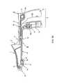
- FIG. 1is a side cross-sectional view of an exemplary embodiment of a device according to the present disclosure in an open position
- FIG. 1Ais a side cross-sectional view of an alternate embodiment of the device of the present disclosure in an open position
- FIG. 1Bis a side cross-sectional view of another alternate embodiment of the device of the present disclosure shown in an open position
- FIG. 1Cis a side cross-sectional view of another alternate embodiment of the device of the present disclosure shown in an open position
- FIG. 2is a side cross-sectional view of the device of FIG. 1 in a closed position
- FIG. 2Ais a side cross-sectional view of the device of FIG. 1 in a fully open position
- FIG. 2Bis an exploded view of the device of FIG. 1
- FIG. 2Cis a side cross-sectional view of the device of FIG. 1 in a partially closed position wherein the tissue is compressed by the second closure member
- FIG. 2 dis a side cross-sectional view similar to FIG. 2 c showing movement of the first closure member with respect to the second closure member and tensioning of the spring
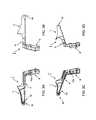
- FIG. 3Ais a left side cross-sectional view of a first part (component) of the device of FIGS. 1 and 2 ;
- FIG. 3Bis a right side cross-sectional view of the first part shown in FIG. 3A ;
- FIG. 3Cis a right side perspective view of the first part shown in FIG. 3A ;
- FIG. 3Dis a left side perspective view of the first part shown in FIG. 3A ;
- FIG. 4Ais a right side view of a second part (component) of the device of FIG. 1 ;
- FIG. 4Bis a rear view of the second part shown in FIG. 4A ;
- FIG. 4Cis a right side view of the second part shown in FIG. 4A ;
- FIG. 4Dis a perspective view of the second part shown in FIG. 4A ;
- FIG. 5Ais a side view of a third part (component) of the device of FIG. 1 ;
- FIG. 5Bis a top view of the third part shown in FIG. 5A ;
- FIG. 5Cis a right side perspective view of the third part shown in FIG. 5A ;
- FIG. 5Dis a left side perspective view of the third part shown in FIG. 5A ;
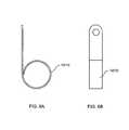
- FIG. 6Ais a lateral side view of a spring used in the device of FIG. 1 ;
- FIG. 6Bis a front view of the spring illustrated in FIG. 6A .
- FIGS. 1-6Bshow various components of an exemplary embodiment of a device according to the present disclosure.
- the exemplary devicehas three primary parts, e.g., a first part or component (or member) I, a second part or component (or member) II and a third part or component (or member) III.
- the first part I(as shown in, e.g., FIGS. 1-3D ) comprises a hollow portion 1 which includes a tapered end or insertion tip 16 which is structured or configured for insertion into or propagation through a bodily lumen or another anatomical structure, a first handle grip 5 (which is proximal (closer to the user) with respect to the tip 16 ) and a connecting section 4 .
- the second part II(as shown in, e.g., FIGS. 1 , 2 , 2 A, 2 B and 4 A- 4 D) comprises a second handle grip 8 (which is proximal with respect to the tip 16 ) and a first closure member 9 , which can be non-releasibly connected.
- the third part III(as shown in, e.g., FIGS. 1 , 2 , 2 A, 2 B and 5 A- 5 D) comprises a second closure member 10 .
- the exemplary deviceprovides a handle 2 ( FIG. 1 ) which comprises the first handle grip 5 of the first part I and the second handle grip 8 of the second part II.
- the exemplary devicehas a first spring 12 and a second spring 13 , whereas the first spring 12 can be provided closer to the tip 16 than the second spring 13 , and both of which can have two or more fixation points.
- the second spring 13can be provided more proximal than the first spring 12 .
- the first spring 12can include (i) a first fixation point 12 a provided at or on the first handle grip 5 of the first part I (as also shown in FIGS. 3A and 3C ) and (ii) a second fixation point 14 (as also shown in FIGS.
- the second spring 13also has (i) a first fixation point 13 a located on or at the second closure member 10 of third part III (as also shown in FIGS. 5B and 5C ), and (ii) a second fixation point 15 located on and below the surface of the first closure member 9 of second part II (as also shown in FIG. 4D ).
- the second spring 13When the exemplary device is assembled, the second spring 13 is provided or positioned just below a particular surface 20 of the second closure member 10 , while also being coupled to the first fixation point 13 a thereof.
- Any of the fixation points 12 a , 13 a , 14 and/or 15can be metal and/or plastic knob(s) or other members to which the respective first and second springs 12 , 13 can be attached, clipped unto and/or adhered to, e.g., possibly with glue, clips, etc.
- the exemplary details of the first and second springs 12 , 13are illustrated in FIGS. 6A and 6B . However, it should be understood that other shapes and/or or sizes of the springs are conceivable and are within the scope of the exemplary embodiments of the present disclosure.
- FIGS. 1 , 2 , 2 A and 2 Bshow that the first spring 12 couples the first part I and the second part II to one another.
- FIGS. 1 , 2 , 2 A and 2 Bshow that the first spring 12 couples the first part I and the second part II to one another.
- the second spring 13couples the first and second closure members 9 , 10 of respective parts II and III to one another, which are slidably engaged with each other.
- the exemplary deviceincludes a window 6 which is enclosed between and formed by at least two opposing clamping surfaces, e.g., a first opposing clamping surface 7 a (which is part of the hollow portion 1 of the first part I), and a second opposing clamping surface 7 b (which is part of the second closure member 10 of the third part III and provided on the edge thereof).
- the second clamping surface 7 bis moved toward the first clamping surface 7 a by moving the third part III toward the first clamping surface 7 a to close or reduce the size of the window 6 and away from such first clamping surface 7 a to open or increase the size of the window 6 .
- Such movement of the third part IIIcan be actuated by squeezing and/or releasing the handle 2 of the exemplary device.
- the window 6 sizeis reduced, by, e.g., being closed until it meets an obstacle, such as, for example, a protruding tissue 17 (as shown in FIG. 1 ).
- the window 6is intended to be closed when the first and second opposing clamping surfaces 7 a , 7 b meet each other (as shown in FIG. 2 ).
- the window 6becomes bigger when the second closure member 10 moves away from the first opposing clamping surface 7 a of the first part I, and smaller when the second closure member 10 moves towards the first opposing clamping surface 7 a of the first part I.
- the second handle grip 8 of the second part II.when the second handle grip 8 of the second part II. is moved toward the first handle grip 5 of the first part I (see FIG. 2 ), for example, during a squeezing motion by the hand of the operator, the second part II pulls on the second spring 13 .
- the second spring 13is connected at one end thereof to the second part II via the second fixation point 15 (as shown in FIGS. 2A , 2 B and 4 D) which is located on and below a surface of the first closure member 9 of the second part II.
- the strength of the second spring 13is selected or configured so as to facilitate the second main part II to pull the second closure member 10 of the third part III in the same direction as the direction of propagation of the first closure member 9 .
- the second closure member 10 of the third part IIIis moved by the first closure member 9 of the second part II forward toward the first clamping surface 7 a by pulling (e.g., likely without significant stretching) the second spring 13 , provided that the second closure member 10 does not meet the obstacle in the window 6 . Indeed, such pulling motion is effectuated since another end of the second spring 13 is connected to the first fixation point 13 a located on or at the second closure member 10 and below the particular surface 20 thereof (as also shown in FIGS. 5B and 5C ).
- the second spring 13acts as a spring coupling arrangement between the second part II and the third part III.
- the second closure member 10 of the third part IIImeets the obstacle in the window 6 (e.g., the protruding tissue)
- the forward motion of the second closure member 10 in the same direction as that of the second part IIstops completely or for the most part as shown in FIG. 2C .
- the second part II of the exemplary devicecontinues to move forward in the same direction, and also (simultaneously) causes the second spring 13 to stretch as shown in FIG. 2D .
- the first closure member 9 of second part IIslides over the second closure member 10 of the third part III towards the first clamping surface 7 a or the end or tip 16 , without further affecting the forward movement of the second closure member 10 of the third part III and absent any further significant compression of the tissue situated within the window 6 (see FIG. 2D ).
- This exemplary effectis caused by the fact that when the second opposing clamping surface 7 b of the second closure member 10 of the third part III contacts and attempts to press on the tissue provided within the window 6 , this negative pressure causes the second spring 13 to stretch. In this manner, while the second closure member 10 of the third part III is prevented from moving forward by the tissue, a tension is continued on the second spring 13 , allowing the first closure member 9 of the second part II to continue its forward motion toward the tip 16 . Such tension on the second spring 13 facilitates an approximately constant compression on the tissue. Indeed, as a result, a constant tissue compression (e.g., on the tissue or on any other object) can be accomplished in the window 6 .
- a constant tissue compressione.g., on the tissue or on any other object
- Such constant tension or compressioncan be largely separate from or independent of the force exerted by the operator on the handle 2 , for example, the compression of the tissue can be mainly dependent upon various properties of the second spring 13 , the connections thereof to the second and third parts II, III, and the properties of the compressed tissue 17 in the window 6 .
- the first spring 12can be useful in facilitating the operation of the exemplary device.
- the second handle grip 8 of part IIis moved toward the first handle grip 5 of part I (see arrow of FIG. 2 ), e.g., during the squeezing motion by the hand of the operator, the second part II is simultaneously pulled on and stretches the first spring 12 (as shown in FIG. 2 ). This is because one end of the first spring 12 is coupled to the second fixation point 14 (as shown in FIGS.
- first spring 12located on and below the surface of the first closure member 9 of the second part II, and the other end of the first spring 12 is coupled to the first fixation point 12 a provided at or on the first handle grip 5 of the first part I (as shown in FIGS. 3A and 3C ). In this manner, the first spring 12 is stretched by the forward movement of the first closure member 9 of the second part II toward the first clamping surface 7 a or the end or tip 16 of the first part I, while the first part I is stationary with respect to the tip 16 .
- the first spring 12has the tension to cause itself to return to its original (e.g., non-stretched or less-stretch) configuration, thereby pulling on the first closure member 9 of the second part II until the second part II returns proximally to its non-deployed (e.g., open or original) position.
- thisis caused by the first spring 12 being attached to a stationary first part I via the first fixation point 12 a , and pulling the first closure member 9 of the second part II back to its original position due to the first spring 12 being connected to the second fixation point 14 of the first closure member 9 .
- the second part IIin the process of returning to its non-deployed position (shown in FIG. 2A ) with the assistance of the first spring 12 , the second part II also pulls on and effectuates further tension of the second spring 13 , which pulls back the second closure member 10 due to its coupling to the first fixation point 13 a thereof until the second closure member 10 returns to its non-deployed position.
- the window 6becomes enlarged, e.g., until it is fully open (as shown in FIG. 2A ).
- FIGS. 1A and 1Billustrate an electrode provided at or near the contacting surface as referenced above.
- the electrode 20 in FIG. 1Ais shown embedded in the first part I.
- the electrode 22is provided on second part II near the contacting surface of the clamping surface.
- FIG. 1Cillustrates an illumination arrangement 24 on the second part II to provide light to the anatomical structure.
Landscapes
- Health & Medical Sciences (AREA)
- Life Sciences & Earth Sciences (AREA)
- Surgery (AREA)
- Engineering & Computer Science (AREA)
- General Health & Medical Sciences (AREA)
- Veterinary Medicine (AREA)
- Biomedical Technology (AREA)
- Heart & Thoracic Surgery (AREA)
- Medical Informatics (AREA)
- Molecular Biology (AREA)
- Animal Behavior & Ethology (AREA)
- Nuclear Medicine, Radiotherapy & Molecular Imaging (AREA)
- Public Health (AREA)
- Vascular Medicine (AREA)
- Pathology (AREA)
- Reproductive Health (AREA)
- Physics & Mathematics (AREA)
- Orthopedic Medicine & Surgery (AREA)
- Biophysics (AREA)
- Optics & Photonics (AREA)
- Radiology & Medical Imaging (AREA)
- Oral & Maxillofacial Surgery (AREA)
- Otolaryngology (AREA)
- Plasma & Fusion (AREA)
- Electromagnetism (AREA)
- Surgical Instruments (AREA)
- Ultra Sonic Daignosis Equipment (AREA)
Abstract
Description
Claims (15)
Priority Applications (5)
| Application Number | Priority Date | Filing Date | Title |
|---|---|---|---|
| US13/094,173US8968275B2 (en) | 2010-04-26 | 2011-04-26 | Apparatus and method for effecting at least one anatomical structure |
| US13/716,184US9833250B2 (en) | 2010-04-26 | 2012-12-16 | Apparatus and method for effecting at least one anatomical structure |
| US14/106,600US9011317B2 (en) | 2010-04-26 | 2013-12-13 | Gentle hemorrhoid treatment offering a substantially painless healing |
| US14/621,678US9883879B2 (en) | 2010-04-26 | 2015-02-13 | Apparatus for treating hemorrhoids |
| US14/667,052US9949631B2 (en) | 2010-04-26 | 2015-03-24 | Gentle hemorrhoid treatment offering a substantially painless healing |
Applications Claiming Priority (2)
| Application Number | Priority Date | Filing Date | Title |
|---|---|---|---|
| US32800510P | 2010-04-26 | 2010-04-26 | |
| US13/094,173US8968275B2 (en) | 2010-04-26 | 2011-04-26 | Apparatus and method for effecting at least one anatomical structure |
Related Child Applications (3)
| Application Number | Title | Priority Date | Filing Date |
|---|---|---|---|
| US13/282,439Continuation-In-PartUS8632458B2 (en) | 2010-04-26 | 2011-10-26 | Gentle hemorrhoid treatment offering a substantially painless healing |
| US13/716,184ContinuationUS9833250B2 (en) | 2010-04-26 | 2012-12-16 | Apparatus and method for effecting at least one anatomical structure |
| US14/621,678ContinuationUS9883879B2 (en) | 2010-04-26 | 2015-02-13 | Apparatus for treating hemorrhoids |
Publications (2)
| Publication Number | Publication Date |
|---|---|
| US20110288538A1 US20110288538A1 (en) | 2011-11-24 |
| US8968275B2true US8968275B2 (en) | 2015-03-03 |
Family
ID=44904328
Family Applications (3)
| Application Number | Title | Priority Date | Filing Date |
|---|---|---|---|
| US13/094,173Active2031-09-20US8968275B2 (en) | 2010-04-26 | 2011-04-26 | Apparatus and method for effecting at least one anatomical structure |
| US13/716,184Active2033-09-27US9833250B2 (en) | 2010-04-26 | 2012-12-16 | Apparatus and method for effecting at least one anatomical structure |
| US14/621,678Active2031-09-22US9883879B2 (en) | 2010-04-26 | 2015-02-13 | Apparatus for treating hemorrhoids |
Family Applications After (2)
| Application Number | Title | Priority Date | Filing Date |
|---|---|---|---|
| US13/716,184Active2033-09-27US9833250B2 (en) | 2010-04-26 | 2012-12-16 | Apparatus and method for effecting at least one anatomical structure |
| US14/621,678Active2031-09-22US9883879B2 (en) | 2010-04-26 | 2015-02-13 | Apparatus for treating hemorrhoids |
Country Status (8)
| Country | Link |
|---|---|
| US (3) | US8968275B2 (en) |
| EP (1) | EP2563234B1 (en) |
| JP (1) | JP5796065B2 (en) |
| KR (1) | KR101605934B1 (en) |
| CN (2) | CN102946811B (en) |
| AU (1) | AU2011248672B2 (en) |
| CA (1) | CA2801171C (en) |
| WO (1) | WO2011139665A2 (en) |
Cited By (3)
| Publication number | Priority date | Publication date | Assignee | Title |
|---|---|---|---|---|
| US9883879B2 (en) | 2010-04-26 | 2018-02-06 | Covidien Lp | Apparatus for treating hemorrhoids |
| US10245061B2 (en) | 2004-03-16 | 2019-04-02 | Covidien Lp | Treatment method including tissue occlusion device |
| US11497507B2 (en) | 2017-02-19 | 2022-11-15 | Orpheus Ventures, Llc | Systems and methods for closing portions of body tissue |
Families Citing this family (3)
| Publication number | Priority date | Publication date | Assignee | Title |
|---|---|---|---|---|
| US8632458B2 (en) | 2011-10-26 | 2014-01-21 | Macroplata Inc. | Gentle hemorrhoid treatment offering a substantially painless healing |
| CN106456365B (en)* | 2014-05-07 | 2019-12-13 | 侯赛因·耶梯柯 | Macular hole repair instrument |
| CN116983070B (en)* | 2023-09-06 | 2023-12-29 | 浙江伽奈维医疗科技有限公司 | Tissue clamping device |
Citations (78)
| Publication number | Priority date | Publication date | Assignee | Title |
|---|---|---|---|---|
| US457787A (en) | 1891-08-18 | Rectal | ||
| US2482971A (en) | 1947-07-11 | 1949-09-27 | Golson Kelly Kendall | Self-illuminated transparent proctoscope |
| US3382873A (en) | 1965-06-30 | 1968-05-14 | Banich Francis Edward | Angulated hemorrhoid ligator |
| US3760810A (en) | 1970-12-11 | 1973-09-25 | Hoorn M Van | Surgical ligating instrument of the endoscope type |
| US4257419A (en) | 1978-12-14 | 1981-03-24 | Mo Och Domsjo Aktiebolag | Suction-assisted hemorrhoid ligator |
| JPH01272139A (en) | 1988-04-23 | 1989-10-31 | Ricoh Co Ltd | Forming method of multilayer interconnection |
| US5318589A (en)* | 1992-04-15 | 1994-06-07 | Microsurge, Inc. | Surgical instrument for endoscopic surgery |
| US5402772A (en) | 1991-05-29 | 1995-04-04 | Origin Medsystems, Inc. | Endoscopic expandable retraction device |
| US5411508A (en) | 1991-10-29 | 1995-05-02 | The Trustees Of Columbia University In The City Of New York | Gastrointestinal approximating and tissue attaching device |
| US5443472A (en)* | 1993-10-08 | 1995-08-22 | Li Medical Technologies, Inc. | Morcellator system |
| EP0736285A2 (en) | 1995-04-04 | 1996-10-09 | United States Surgical Corporation | Surgical cutting apparatus |
| US5570692A (en) | 1995-05-19 | 1996-11-05 | Hayashi Denki Co. Ltd. | Ultrasonic doppler blood flow detector for hemorrhoid artery ligation |
| WO1997013451A1 (en) | 1995-10-10 | 1997-04-17 | Conceptus, Inc. | Access catheter and method for maintaining separation between a falloposcope and a tubal wall |
| US5655698A (en) | 1994-07-13 | 1997-08-12 | Yoon; Inbae | Surgical stapler with curved jaws |
| US5665062A (en) | 1995-01-23 | 1997-09-09 | Houser; Russell A. | Atherectomy catheter and RF cutting method |
| US5947983A (en) | 1998-03-16 | 1999-09-07 | Boston Scientific Corporation | Tissue cutting and stitching device and method |
| US5968033A (en)* | 1997-11-03 | 1999-10-19 | Fuller Research Corporation | Optical delivery system and method for subsurface tissue irradiation |
| US6019733A (en) | 1997-09-19 | 2000-02-01 | United States Surgical Corporation | Biopsy apparatus and method |
| US6032673A (en)* | 1994-10-13 | 2000-03-07 | Femrx, Inc. | Methods and devices for tissue removal |
| US6102271A (en) | 1998-11-23 | 2000-08-15 | Ethicon Endo-Surgery, Inc. | Circular stapler for hemorrhoidal surgery |
| US6119913A (en) | 1996-06-14 | 2000-09-19 | Boston Scientific Corporation | Endoscopic stapler |
| US6126594A (en) | 1998-07-21 | 2000-10-03 | Bayer; Izhack | Anoscope for internal hemorrhoidectomy |
| US6142931A (en) | 1997-10-06 | 2000-11-07 | Olympus Optical Co., Ltd. | Guide tube unit for endoscope and method for resecting a tissue |
| US6142933A (en) | 1998-11-23 | 2000-11-07 | Ethicon Endo-Surgery, Inc. | Anoscope for hemorrhoidal surgery |
| US6179832B1 (en) | 1997-09-11 | 2001-01-30 | Vnus Medical Technologies, Inc. | Expandable catheter having two sets of electrodes |
| US6264086B1 (en) | 1994-12-07 | 2001-07-24 | Mcguckin, Jr. James F. | Surgical apparatus and method |
| US6277066B1 (en) | 1999-04-30 | 2001-08-21 | Civco Medical Instruments Inc. | Endocavity imaging sensor positioning apparatus and method |
| US6277065B1 (en) | 1998-03-20 | 2001-08-21 | Boston Scientific Corporation | Anchoring and positioning device and method for an endoscope |
| US6343731B1 (en) | 1998-06-19 | 2002-02-05 | Scimed Life Systems, Inc. | Method and device for full thickness resectioning of an organ |
| GB2365340A (en) | 2000-05-23 | 2002-02-20 | Queen Mary & Westfield College | Medical tissue resection device for removing tissue comprising a cavity of variable volume for receiving tissue & means for removing the tissue thus received |
| US6398795B1 (en) | 2000-11-30 | 2002-06-04 | Scimed Life Systems, Inc. | Stapling and cutting in resectioning for full thickness resection devices |
| US6428473B1 (en) | 2000-02-18 | 2002-08-06 | Genzyme Corporation | Illuminated rectal retractor |
| US20020111639A1 (en) | 2001-01-09 | 2002-08-15 | Armstrong David N. | Multiple band ligator and anoscope system and method for using same |
| US6478210B2 (en) | 2000-10-25 | 2002-11-12 | Scimed Life Systems, Inc. | Method and device for full thickness resectioning of an organ |
| US20020173786A1 (en) | 2001-05-21 | 2002-11-21 | Kortenbach Juergen A. | Methods and apparatus for on-endoscope instruments having end effectors and combinations of on-endoscope and through-endoscope instruments |
| US6494881B1 (en) | 1997-09-30 | 2002-12-17 | Scimed Life Systems, Inc. | Apparatus and method for electrode-surgical tissue removal having a selectively insulated electrode |
| US6575978B2 (en) | 2001-04-05 | 2003-06-10 | Spineology, Inc. | Circumferential resecting reamer tool |
| US6595917B2 (en) | 2001-02-27 | 2003-07-22 | German Nieto | Disposable speculum with included light and mechanisms for examination and gynecological surgery |
| US6616603B1 (en) | 2000-09-01 | 2003-09-09 | Sergio Bicocchi | Anoscope |
| WO2004004555A1 (en) | 2002-07-09 | 2004-01-15 | Dwl Elektronische Systeme Gmbh | Proctoscope |
| US20040033202A1 (en) | 2002-06-10 | 2004-02-19 | Elan Pharma International, Ltd. | Nanoparticulate sterol formulations and novel sterol combinations |
| US6695198B2 (en) | 1998-06-19 | 2004-02-24 | Scimed Life Systems, Inc. | Integrated surgical staple retainer for a full thickness resectioning device |
| US6805273B2 (en) | 2002-11-04 | 2004-10-19 | Federico Bilotti | Surgical stapling instrument |
| US20050119523A1 (en) | 2003-09-03 | 2005-06-02 | Guided Delivery Systems, Inc. | Cardiac visualization devices and methods |
| US6923806B2 (en) | 2000-04-27 | 2005-08-02 | Atricure Inc. | Transmural ablation device with spring loaded jaws |
| US6938814B2 (en) | 2002-05-24 | 2005-09-06 | Boston Scientific Scimed, Inc. | Full thickness resectioning device |
| US20050277975A1 (en) | 2004-06-09 | 2005-12-15 | Usgi Medical Corp. | Methods and apparatus for creating a working space within a body lumen or cavity |
| US6979290B2 (en) | 2002-05-30 | 2005-12-27 | The Board Of Trustees Of The Leland Stanford Junior University | Apparatus and methods for coronary sinus access |
| US20060049231A1 (en) | 2004-07-30 | 2006-03-09 | Leiboff Arnold R | Surgical stapling instrument and method for its use |
| US7014646B2 (en) | 2001-08-24 | 2006-03-21 | Boston Scientific Scimed, Inc. | Endoscopic resection devices and related methods of use |
| US7029438B2 (en) | 2001-11-20 | 2006-04-18 | Medsurge Medical Products, Corp. | Anoscope |
| US20060200040A1 (en)* | 2005-03-04 | 2006-09-07 | Ethicon Endo-Surgery, Inc. | Biopsy device with variable side aperture |
| US7118528B1 (en) | 2004-03-16 | 2006-10-10 | Gregory Piskun | Hemorrhoids treatment method and associated instrument assembly including anoscope and cofunctioning tissue occlusion device |
| JP2006288431A (en) | 2005-04-05 | 2006-10-26 | Olympus Medical Systems Corp | Ultrasonic surgical device |
| US20060264706A1 (en) | 2004-03-16 | 2006-11-23 | Gregory Piskun | Endoluminal treatment method and associated surgical assembly including tissue occlusion device |
| US7169115B2 (en) | 2003-09-29 | 2007-01-30 | Ethicon Endo-Surgery, Inc. | Endoscopic mucosal resection device with overtube and method of use |
| WO2007017854A2 (en) | 2005-08-08 | 2007-02-15 | Smart Medical Systems Ltd. | Balloon guided endoscopy |
| WO2007032776A1 (en) | 2005-09-12 | 2007-03-22 | Wilson-Cook Medical Inc. | Anoscope |
| US20070255207A1 (en) | 2003-12-11 | 2007-11-01 | Masanori Hangai | Balloon Catheter |
| US20080083813A1 (en)* | 2006-10-05 | 2008-04-10 | Michael Zemlok | Method and force-limiting handle mechanism for a surgical instrument |
| US20080103498A1 (en)* | 1998-02-19 | 2008-05-01 | Curon Medical, Inc. | Systems and methods for treating dysfunctions in the intestines and rectum that adapt to the anatomic form and structure of different individuals |
| US20080132835A1 (en) | 2005-06-02 | 2008-06-05 | Olympus Corporation | Balloon catheter |
| US20080262511A1 (en) | 2007-04-18 | 2008-10-23 | Delaney Conor P | Anoscope for Inspection and/or Surgery |
| US20080277448A1 (en)* | 2001-09-27 | 2008-11-13 | Roby Mark S | Surgical stapling device with coated knife blade |
| US7452329B2 (en) | 2003-01-21 | 2008-11-18 | Thd S.P.A. | Retractor for operations on the arteria haemorroidalis |
| US20090025910A1 (en) | 2007-07-27 | 2009-01-29 | Paul Hoffman | Vapor chamber structure with improved wick and method for manufacturing the same |
| US20090182350A1 (en)* | 2008-01-16 | 2009-07-16 | Mcgown George Percy | Instrucment and method for treatment of hemorrhoids |
| US20090182332A1 (en)* | 2008-01-15 | 2009-07-16 | Ethicon Endo-Surgery, Inc. | In-line electrosurgical forceps |
| US20090187074A1 (en) | 2008-01-17 | 2009-07-23 | Nidus Medical, Llc | Epicardial access and treatment systems |
| US20090259110A1 (en) | 2006-02-14 | 2009-10-15 | Metech S.R.L. | Process and a device for surgical treatment of rectal and haemorrhoidal prolapse |
| US20100023023A1 (en)* | 2006-02-15 | 2010-01-28 | Drago Popovic | Device, clip, endoscope and method for the intraluminal treatment of tissue, e.g. hemorrhoids |
| WO2010041280A1 (en) | 2008-10-06 | 2010-04-15 | Thd Spa | A device for surgical operations on a prolapse |
| WO2011041578A2 (en) | 2009-10-01 | 2011-04-07 | Macroplata, Inc. | Detachable balloon catheter |
| US7972299B2 (en) | 2007-07-09 | 2011-07-05 | Cook Medical Technologies Llc | Balloon catheter with deflation mechanism |
| WO2011084616A2 (en) | 2009-12-16 | 2011-07-14 | Macroplata, Inc. | Arrangements and methods for effecting an endoluminal anatomical structure |
| US8002795B2 (en)* | 2005-06-03 | 2011-08-23 | Tyco Healthcare Group, L.P. | Surgical instruments employing sensors |
| US20120059394A1 (en) | 2009-02-17 | 2012-03-08 | The Board Of Trustees Of The Leland Stanford Junior University | Closure device and method |
| US20130053833A1 (en)* | 2010-01-27 | 2013-02-28 | Carefusion 2200, Inc. | Overforce mechanism |
Family Cites Families (12)
| Publication number | Priority date | Publication date | Assignee | Title |
|---|---|---|---|---|
| US859150A (en)* | 1906-07-19 | 1907-07-02 | Robert Taylor | Tonsillotome and like instrument. |
| US5451227A (en)* | 1989-04-24 | 1995-09-19 | Michaelson; Gary K. | Thin foot plate multi bite rongeur |
| DE4411099C2 (en)* | 1994-03-30 | 1998-07-30 | Wolf Gmbh Richard | Surgical instrument |
| RU2086190C1 (en)* | 1994-04-19 | 1997-08-10 | Вадим Владимирович Половинкин | Device for suture at ablation of internal hemorrhoids |
| US5643248A (en)* | 1995-02-07 | 1997-07-01 | Yoon; Inbae | Medical instrument with force limiting mechanism |
| DE19640896A1 (en)* | 1996-10-04 | 1998-04-23 | Wolf Gmbh Richard | Medical instrument for endoscopic use |
| JP3803467B2 (en)* | 1997-01-31 | 2006-08-02 | オリンパス株式会社 | Guidance aid |
| ITBO20010502A1 (en)* | 2001-08-02 | 2003-02-02 | Anthea S R L | DISPOSABLE DEVICE FOR SURGICAL INTERVENTIONS ON THE HEMORRHOID ARTERY |
| US7608073B2 (en)* | 2004-07-09 | 2009-10-27 | Tyco Healthcare Group Lp | Energy based partial circumferential hemorrhoid repair device |
| ITMI20060281A1 (en)* | 2006-02-15 | 2007-08-16 | Ethicon Endo Surgery Inc | ANOSCOPE CLAMP AND MEETHOD DEVICE FOR TRANSANAL HEMORROID TREATMENT |
| US7506791B2 (en)* | 2006-09-29 | 2009-03-24 | Ethicon Endo-Surgery, Inc. | Surgical stapling instrument with mechanical mechanism for limiting maximum tissue compression |
| KR101605934B1 (en) | 2010-04-26 | 2016-03-23 | 코비디엔 엘피 | Apparatus and method for effecting at least one anatomical structure |
- 2011
- 2011-04-26KRKR1020127030675Apatent/KR101605934B1/enactiveActive
- 2011-04-26EPEP11777898.5Apatent/EP2563234B1/enactiveActive
- 2011-04-26JPJP2013508145Apatent/JP5796065B2/ennot_activeExpired - Fee Related
- 2011-04-26CNCN201180031529.4Apatent/CN102946811B/enactiveActive
- 2011-04-26USUS13/094,173patent/US8968275B2/enactiveActive
- 2011-04-26CACA2801171Apatent/CA2801171C/enactiveActive
- 2011-04-26AUAU2011248672Apatent/AU2011248672B2/ennot_activeCeased
- 2011-04-26WOPCT/US2011/033875patent/WO2011139665A2/enactiveApplication Filing
- 2011-04-26CNCN201510919884.5Apatent/CN105534566B/enactiveActive
- 2012
- 2012-12-16USUS13/716,184patent/US9833250B2/enactiveActive
- 2015
- 2015-02-13USUS14/621,678patent/US9883879B2/enactiveActive
Patent Citations (110)
| Publication number | Priority date | Publication date | Assignee | Title |
|---|---|---|---|---|
| US457787A (en) | 1891-08-18 | Rectal | ||
| US2482971A (en) | 1947-07-11 | 1949-09-27 | Golson Kelly Kendall | Self-illuminated transparent proctoscope |
| US3382873A (en) | 1965-06-30 | 1968-05-14 | Banich Francis Edward | Angulated hemorrhoid ligator |
| US3760810A (en) | 1970-12-11 | 1973-09-25 | Hoorn M Van | Surgical ligating instrument of the endoscope type |
| US4257419A (en) | 1978-12-14 | 1981-03-24 | Mo Och Domsjo Aktiebolag | Suction-assisted hemorrhoid ligator |
| JPH01272139A (en) | 1988-04-23 | 1989-10-31 | Ricoh Co Ltd | Forming method of multilayer interconnection |
| US5402772A (en) | 1991-05-29 | 1995-04-04 | Origin Medsystems, Inc. | Endoscopic expandable retraction device |
| US5411508A (en) | 1991-10-29 | 1995-05-02 | The Trustees Of Columbia University In The City Of New York | Gastrointestinal approximating and tissue attaching device |
| US5318589A (en)* | 1992-04-15 | 1994-06-07 | Microsurge, Inc. | Surgical instrument for endoscopic surgery |
| US5443472A (en)* | 1993-10-08 | 1995-08-22 | Li Medical Technologies, Inc. | Morcellator system |
| US5655698A (en) | 1994-07-13 | 1997-08-12 | Yoon; Inbae | Surgical stapler with curved jaws |
| US6032673A (en)* | 1994-10-13 | 2000-03-07 | Femrx, Inc. | Methods and devices for tissue removal |
| US6264086B1 (en) | 1994-12-07 | 2001-07-24 | Mcguckin, Jr. James F. | Surgical apparatus and method |
| US6872204B2 (en) | 1995-01-23 | 2005-03-29 | Russell A. | Tissue cutting catheter and RF cutting method |
| US5665062A (en) | 1995-01-23 | 1997-09-09 | Houser; Russell A. | Atherectomy catheter and RF cutting method |
| US20040002706A1 (en) | 1995-01-23 | 2004-01-01 | Houser Russell A. | Tissue cutting catheter and RF cutting method |
| US5876369A (en) | 1995-01-23 | 1999-03-02 | Advanced Catheter Engineering | Tissue removing catheter and RF cutting method |
| US6540761B2 (en) | 1995-01-23 | 2003-04-01 | Russell A. Houser | Tissue cutting/tissue removing device with vacuum feature |
| US6214024B1 (en) | 1995-01-23 | 2001-04-10 | Russell U. Houser | Tissue cutting catheter and RF cutting method |
| EP0736285A2 (en) | 1995-04-04 | 1996-10-09 | United States Surgical Corporation | Surgical cutting apparatus |
| US5570692A (en) | 1995-05-19 | 1996-11-05 | Hayashi Denki Co. Ltd. | Ultrasonic doppler blood flow detector for hemorrhoid artery ligation |
| US5716321A (en) | 1995-10-10 | 1998-02-10 | Conceptus, Inc. | Method for maintaining separation between a falloposcope and a tubal wall |
| WO1997013451A1 (en) | 1995-10-10 | 1997-04-17 | Conceptus, Inc. | Access catheter and method for maintaining separation between a falloposcope and a tubal wall |
| US5873815A (en) | 1995-10-10 | 1999-02-23 | Conceptus, Inc. | Access catheter and method for maintaining separation between a falloposcope and a tubal wall |
| US6196966B1 (en) | 1995-10-10 | 2001-03-06 | Conceptus, Inc. | Access catheter and method for maintaining separation between a falloposcope and a tubal wall |
| US5935056A (en) | 1995-10-10 | 1999-08-10 | Conceptus, Inc. | Access catheter and method for maintaining separation between a falloposcope and a tubal wall |
| US6302311B1 (en) | 1996-06-14 | 2001-10-16 | Boston Scientific Corporation | Endoscopic stapler |
| US6119913A (en) | 1996-06-14 | 2000-09-19 | Boston Scientific Corporation | Endoscopic stapler |
| US6179832B1 (en) | 1997-09-11 | 2001-01-30 | Vnus Medical Technologies, Inc. | Expandable catheter having two sets of electrodes |
| US6019733A (en) | 1997-09-19 | 2000-02-01 | United States Surgical Corporation | Biopsy apparatus and method |
| US6494881B1 (en) | 1997-09-30 | 2002-12-17 | Scimed Life Systems, Inc. | Apparatus and method for electrode-surgical tissue removal having a selectively insulated electrode |
| US6142931A (en) | 1997-10-06 | 2000-11-07 | Olympus Optical Co., Ltd. | Guide tube unit for endoscope and method for resecting a tissue |
| US5968033A (en)* | 1997-11-03 | 1999-10-19 | Fuller Research Corporation | Optical delivery system and method for subsurface tissue irradiation |
| US20080103498A1 (en)* | 1998-02-19 | 2008-05-01 | Curon Medical, Inc. | Systems and methods for treating dysfunctions in the intestines and rectum that adapt to the anatomic form and structure of different individuals |
| US5947983A (en) | 1998-03-16 | 1999-09-07 | Boston Scientific Corporation | Tissue cutting and stitching device and method |
| US6277065B1 (en) | 1998-03-20 | 2001-08-21 | Boston Scientific Corporation | Anchoring and positioning device and method for an endoscope |
| US7059331B2 (en) | 1998-06-19 | 2006-06-13 | Boston Scientific Scimed, Inc. | Method and device for full thickness resectioning of an organ |
| US6840423B2 (en) | 1998-06-19 | 2005-01-11 | Scimed Life Systems, Inc. | Integrated surgical staple retainer for a full thickness resectioning device |
| US6866178B2 (en) | 1998-06-19 | 2005-03-15 | Boston Scientific Scimed, Inc. | Integrated surgical staple retainer for a full thickness resectioning device |
| US6695198B2 (en) | 1998-06-19 | 2004-02-24 | Scimed Life Systems, Inc. | Integrated surgical staple retainer for a full thickness resectioning device |
| US20060191975A1 (en) | 1998-06-19 | 2006-08-31 | Boston Scientific Scimed, Inc. | Method and device for full thickness resectioning of an organ |
| US6343731B1 (en) | 1998-06-19 | 2002-02-05 | Scimed Life Systems, Inc. | Method and device for full thickness resectioning of an organ |
| US7546939B2 (en) | 1998-06-19 | 2009-06-16 | Boston Scientific Scimed, Inc. | Method and device for full thickness resectioning of an organ |
| US6874669B2 (en) | 1998-06-19 | 2005-04-05 | Boston Scientific Scimed, Inc. | Integrated surgical staple retainer for a full thickness resectioning device |
| US6126594A (en) | 1998-07-21 | 2000-10-03 | Bayer; Izhack | Anoscope for internal hemorrhoidectomy |
| US6142933A (en) | 1998-11-23 | 2000-11-07 | Ethicon Endo-Surgery, Inc. | Anoscope for hemorrhoidal surgery |
| US6102271A (en) | 1998-11-23 | 2000-08-15 | Ethicon Endo-Surgery, Inc. | Circular stapler for hemorrhoidal surgery |
| US6277066B1 (en) | 1999-04-30 | 2001-08-21 | Civco Medical Instruments Inc. | Endocavity imaging sensor positioning apparatus and method |
| US6428473B1 (en) | 2000-02-18 | 2002-08-06 | Genzyme Corporation | Illuminated rectal retractor |
| US6923806B2 (en) | 2000-04-27 | 2005-08-02 | Atricure Inc. | Transmural ablation device with spring loaded jaws |
| GB2365340A (en) | 2000-05-23 | 2002-02-20 | Queen Mary & Westfield College | Medical tissue resection device for removing tissue comprising a cavity of variable volume for receiving tissue & means for removing the tissue thus received |
| US6616603B1 (en) | 2000-09-01 | 2003-09-09 | Sergio Bicocchi | Anoscope |
| US6478210B2 (en) | 2000-10-25 | 2002-11-12 | Scimed Life Systems, Inc. | Method and device for full thickness resectioning of an organ |
| US7882995B2 (en) | 2000-11-30 | 2011-02-08 | Boston Scientific Scimed, Inc. | Stapling and cutting in resectioning for full thickness resection devices |
| US7334718B2 (en) | 2000-11-30 | 2008-02-26 | Boston Scientific Scimed, Inc. | Stapling and cutting in resectioning for full thickness resection devices |
| US20040158263A1 (en) | 2000-11-30 | 2004-08-12 | Mcalister Gary | Stapling and cutting in resectioning for full thickness resection devices |
| US6716222B2 (en) | 2000-11-30 | 2004-04-06 | Scimed Life Systems, Inc. | Stapling and cutting in resectioning for full thickness resection devices |
| US6398795B1 (en) | 2000-11-30 | 2002-06-04 | Scimed Life Systems, Inc. | Stapling and cutting in resectioning for full thickness resection devices |
| US20020111639A1 (en) | 2001-01-09 | 2002-08-15 | Armstrong David N. | Multiple band ligator and anoscope system and method for using same |
| US6595917B2 (en) | 2001-02-27 | 2003-07-22 | German Nieto | Disposable speculum with included light and mechanisms for examination and gynecological surgery |
| US6575978B2 (en) | 2001-04-05 | 2003-06-10 | Spineology, Inc. | Circumferential resecting reamer tool |
| US6808491B2 (en) | 2001-05-21 | 2004-10-26 | Syntheon, Llc | Methods and apparatus for on-endoscope instruments having end effectors and combinations of on-endoscope and through-endoscope instruments |
| US20020173786A1 (en) | 2001-05-21 | 2002-11-21 | Kortenbach Juergen A. | Methods and apparatus for on-endoscope instruments having end effectors and combinations of on-endoscope and through-endoscope instruments |
| US7014646B2 (en) | 2001-08-24 | 2006-03-21 | Boston Scientific Scimed, Inc. | Endoscopic resection devices and related methods of use |
| US20080277448A1 (en)* | 2001-09-27 | 2008-11-13 | Roby Mark S | Surgical stapling device with coated knife blade |
| US7029438B2 (en) | 2001-11-20 | 2006-04-18 | Medsurge Medical Products, Corp. | Anoscope |
| US6938814B2 (en) | 2002-05-24 | 2005-09-06 | Boston Scientific Scimed, Inc. | Full thickness resectioning device |
| US6979290B2 (en) | 2002-05-30 | 2005-12-27 | The Board Of Trustees Of The Leland Stanford Junior University | Apparatus and methods for coronary sinus access |
| US8016748B2 (en) | 2002-05-30 | 2011-09-13 | The Board Of Trustees Of The Leland Stanford Jr. University | Apparatus and methods for coronary sinus access |
| US20040033202A1 (en) | 2002-06-10 | 2004-02-19 | Elan Pharma International, Ltd. | Nanoparticulate sterol formulations and novel sterol combinations |
| WO2004004555A1 (en) | 2002-07-09 | 2004-01-15 | Dwl Elektronische Systeme Gmbh | Proctoscope |
| US6805273B2 (en) | 2002-11-04 | 2004-10-19 | Federico Bilotti | Surgical stapling instrument |
| US7452329B2 (en) | 2003-01-21 | 2008-11-18 | Thd S.P.A. | Retractor for operations on the arteria haemorroidalis |
| US20050119523A1 (en) | 2003-09-03 | 2005-06-02 | Guided Delivery Systems, Inc. | Cardiac visualization devices and methods |
| US7534204B2 (en) | 2003-09-03 | 2009-05-19 | Guided Delivery Systems, Inc. | Cardiac visualization devices and methods |
| US7169115B2 (en) | 2003-09-29 | 2007-01-30 | Ethicon Endo-Surgery, Inc. | Endoscopic mucosal resection device with overtube and method of use |
| US20070255207A1 (en) | 2003-12-11 | 2007-11-01 | Masanori Hangai | Balloon Catheter |
| US8100822B2 (en) | 2004-03-16 | 2012-01-24 | Macroplata Systems, Llc | Anoscope for treating hemorrhoids without the trauma of cutting or the use of an endoscope |
| US20090318940A1 (en) | 2004-03-16 | 2009-12-24 | Macroplata Systems, Llc | Endoluminal treatment method and associated surgical assembly including tissue occlusion device |
| US20100056870A1 (en) | 2004-03-16 | 2010-03-04 | Macroplata Systems, Llc | Endoluminal treatment method and associated surgical assembly including tissue occlusion device |
| US20100010297A1 (en) | 2004-03-16 | 2010-01-14 | Macroplata Systems, Llc | Endoluminal treatment method and associated surgical assembly including tissue occlusion device |
| US20100010296A1 (en) | 2004-03-16 | 2010-01-14 | Macroplata Systems, Llc | Endoluminal treatment method and associated surgical assembly including tissue occlusion device |
| US7118528B1 (en) | 2004-03-16 | 2006-10-10 | Gregory Piskun | Hemorrhoids treatment method and associated instrument assembly including anoscope and cofunctioning tissue occlusion device |
| US20060264706A1 (en) | 2004-03-16 | 2006-11-23 | Gregory Piskun | Endoluminal treatment method and associated surgical assembly including tissue occlusion device |
| US20050277975A1 (en) | 2004-06-09 | 2005-12-15 | Usgi Medical Corp. | Methods and apparatus for creating a working space within a body lumen or cavity |
| US20060049231A1 (en) | 2004-07-30 | 2006-03-09 | Leiboff Arnold R | Surgical stapling instrument and method for its use |
| US7717861B2 (en)* | 2005-03-04 | 2010-05-18 | Ethicon Endo-Surgery, Inc. | Biopsy device with variable side aperture |
| US20060200040A1 (en)* | 2005-03-04 | 2006-09-07 | Ethicon Endo-Surgery, Inc. | Biopsy device with variable side aperture |
| JP2006288431A (en) | 2005-04-05 | 2006-10-26 | Olympus Medical Systems Corp | Ultrasonic surgical device |
| US20090030369A1 (en) | 2005-06-02 | 2009-01-29 | Olympus Corporation | Balloon catheter |
| US20080132835A1 (en) | 2005-06-02 | 2008-06-05 | Olympus Corporation | Balloon catheter |
| US8002795B2 (en)* | 2005-06-03 | 2011-08-23 | Tyco Healthcare Group, L.P. | Surgical instruments employing sensors |
| WO2007019321A2 (en) | 2005-08-05 | 2007-02-15 | Gregory Piskun | Endoluminal treatment method and associated surgical assembly including tissue occlusion device |
| WO2007017854A2 (en) | 2005-08-08 | 2007-02-15 | Smart Medical Systems Ltd. | Balloon guided endoscopy |
| WO2007032776A1 (en) | 2005-09-12 | 2007-03-22 | Wilson-Cook Medical Inc. | Anoscope |
| US20090259110A1 (en) | 2006-02-14 | 2009-10-15 | Metech S.R.L. | Process and a device for surgical treatment of rectal and haemorrhoidal prolapse |
| US20100023023A1 (en)* | 2006-02-15 | 2010-01-28 | Drago Popovic | Device, clip, endoscope and method for the intraluminal treatment of tissue, e.g. hemorrhoids |
| US20080083813A1 (en)* | 2006-10-05 | 2008-04-10 | Michael Zemlok | Method and force-limiting handle mechanism for a surgical instrument |
| US20080262511A1 (en) | 2007-04-18 | 2008-10-23 | Delaney Conor P | Anoscope for Inspection and/or Surgery |
| US7972299B2 (en) | 2007-07-09 | 2011-07-05 | Cook Medical Technologies Llc | Balloon catheter with deflation mechanism |
| US20090025910A1 (en) | 2007-07-27 | 2009-01-29 | Paul Hoffman | Vapor chamber structure with improved wick and method for manufacturing the same |
| US20090182332A1 (en)* | 2008-01-15 | 2009-07-16 | Ethicon Endo-Surgery, Inc. | In-line electrosurgical forceps |
| US20090182350A1 (en)* | 2008-01-16 | 2009-07-16 | Mcgown George Percy | Instrucment and method for treatment of hemorrhoids |
| US20090187074A1 (en) | 2008-01-17 | 2009-07-23 | Nidus Medical, Llc | Epicardial access and treatment systems |
| WO2010041280A1 (en) | 2008-10-06 | 2010-04-15 | Thd Spa | A device for surgical operations on a prolapse |
| US20120059394A1 (en) | 2009-02-17 | 2012-03-08 | The Board Of Trustees Of The Leland Stanford Junior University | Closure device and method |
| WO2011041578A2 (en) | 2009-10-01 | 2011-04-07 | Macroplata, Inc. | Detachable balloon catheter |
| WO2011084616A2 (en) | 2009-12-16 | 2011-07-14 | Macroplata, Inc. | Arrangements and methods for effecting an endoluminal anatomical structure |
| US20110224494A1 (en) | 2009-12-16 | 2011-09-15 | Macroplata, Inc. | Arrangements and methods for effecting an endoluminal anatomical structure |
| US20130053833A1 (en)* | 2010-01-27 | 2013-02-28 | Carefusion 2200, Inc. | Overforce mechanism |
Non-Patent Citations (12)
| Title |
|---|
| Chinese Appl. No. 200680028706.2 English text of First Office Action (Jun. 20, 2007), Second Office Action (Feb. 5, 2010) and Third Office Action (Nov. 4, 2010). |
| European Search Report dated May 3, 2011 for European Patent Application No. 06789411.3. |
| Japanese Office Action dated Nov. 27, 2014 issued in Japanese Appln. No. 2013-508145. |
| Notice of Reasons for Rejection for Japan Appl. No. 2008-525229 (Aug. 10, 2011 ). |
| PCT/US06/30464 Written Opinion dated Jun. 20, 2007 and International Search Report. |
| PCT/US2006/030464 International Preliminary Report on Patentability (Feb. 5, 2008). |
| PCT/US2006/030464 International Search Report (Jun. 20, 2007). |
| PCT/US2010/050955 International Search Report (Jun. 23, 2011). |
| PCT/US2010/060802 International Preliminary Report on Patentability (Jun. 19, 2012). |
| PCT/US2010/060802 International Search Report (Nov. 17, 2011). |
| PCT/US2011/033875-International Search Report and Written Opinion. |
| PCT/US2011/033875—International Search Report and Written Opinion. |
Cited By (3)
| Publication number | Priority date | Publication date | Assignee | Title |
|---|---|---|---|---|
| US10245061B2 (en) | 2004-03-16 | 2019-04-02 | Covidien Lp | Treatment method including tissue occlusion device |
| US9883879B2 (en) | 2010-04-26 | 2018-02-06 | Covidien Lp | Apparatus for treating hemorrhoids |
| US11497507B2 (en) | 2017-02-19 | 2022-11-15 | Orpheus Ventures, Llc | Systems and methods for closing portions of body tissue |
Also Published As
| Publication number | Publication date |
|---|---|
| JP2013525019A (en) | 2013-06-20 |
| US20150173785A1 (en) | 2015-06-25 |
| CN102946811A (en) | 2013-02-27 |
| JP5796065B2 (en) | 2015-10-21 |
| US9883879B2 (en) | 2018-02-06 |
| CN105534566A (en) | 2016-05-04 |
| KR20130100904A (en) | 2013-09-12 |
| US9833250B2 (en) | 2017-12-05 |
| US20130109926A1 (en) | 2013-05-02 |
| CA2801171A1 (en) | 2011-11-10 |
| AU2011248672B2 (en) | 2014-08-14 |
| WO2011139665A3 (en) | 2012-04-19 |
| CN105534566B (en) | 2019-11-05 |
| US20110288538A1 (en) | 2011-11-24 |
| WO2011139665A2 (en) | 2011-11-10 |
| KR101605934B1 (en) | 2016-03-23 |
| EP2563234A2 (en) | 2013-03-06 |
| EP2563234A4 (en) | 2017-08-09 |
| CA2801171C (en) | 2018-03-06 |
| CN102946811B (en) | 2016-01-06 |
| EP2563234B1 (en) | 2021-12-08 |
Similar Documents
| Publication | Publication Date | Title |
|---|---|---|
| US9883879B2 (en) | Apparatus for treating hemorrhoids | |
| US12178463B2 (en) | Endoluminal treatment method and associated surgical assembly including tissue occlusion device | |
| US7118528B1 (en) | Hemorrhoids treatment method and associated instrument assembly including anoscope and cofunctioning tissue occlusion device | |
| US9949631B2 (en) | Gentle hemorrhoid treatment offering a substantially painless healing | |
| AU2011248672A1 (en) | Apparatus and method for effecting at least one anatomical structure | |
| CN109044525B (en) | Guide wire joint | |
| AU2014262200B2 (en) | Apparatus and method for effecting at least one anatomical structure |
Legal Events
| Date | Code | Title | Description |
|---|---|---|---|
| AS | Assignment | Owner name:MACROPLATA, INC., NEW JERSEY Free format text:ASSIGNMENT OF ASSIGNORS INTEREST;ASSIGNORS:PISKUN, GREGORY;GUTELIUS, PATRICK;SHIKHMAN, OLEG;SIGNING DATES FROM 20100121 TO 20100128;REEL/FRAME:026181/0926 | |
| AS | Assignment | Owner name:COVIDIEN LP, MASSACHUSETTS Free format text:ASSIGNMENT OF ASSIGNORS INTEREST;ASSIGNOR:HET SYSTEMS, LLC;REEL/FRAME:032765/0028 Effective date:20140414 Owner name:MACROPLATA, INC., NEW JERSEY Free format text:ASSIGNMENT OF ASSIGNORS INTEREST;ASSIGNOR:PISKUN, GREGORY;REEL/FRAME:032764/0992 Effective date:20140302 Owner name:HET SYSTEM, LLC, NEW JERSEY Free format text:ASSIGNMENT OF ASSIGNORS INTEREST;ASSIGNOR:MACROPLATA, INC.;REEL/FRAME:032765/0019 Effective date:20140409 Owner name:MACROPLATA, INC., NEW JERSEY Free format text:ASSIGNMENT OF ASSIGNORS INTEREST;ASSIGNOR:SHIKHMAN, OLEG;REEL/FRAME:032765/0016 Effective date:20140302 | |
| AS | Assignment | Owner name:HET SYSTEMS, LLC, NEW JERSEY Free format text:CORRECTIVE ASSIGNMENT TO CORRECT THE RECEIVING PARTY DATA FROM HET SYSTEM, LLC TO HET SYSTEMS, LLC PREVIOUSLY RECORDED ON REEL 032765 FRAME 0019. ASSIGNOR(S) HEREBY CONFIRMS THE INFORMATION CAN BE FOUND IN THE SECOND PARAGRAPH ON PAGE ONE OF THE FILED ASSIGNMENT DOCUMENT;ASSIGNOR:MACROPLATA, INC.;REEL/FRAME:032790/0731 Effective date:20140409 | |
| STCF | Information on status: patent grant | Free format text:PATENTED CASE | |
| MAFP | Maintenance fee payment | Free format text:PAYMENT OF MAINTENANCE FEE, 4TH YEAR, LARGE ENTITY (ORIGINAL EVENT CODE: M1551); ENTITY STATUS OF PATENT OWNER: LARGE ENTITY Year of fee payment:4 | |
| MAFP | Maintenance fee payment | Free format text:PAYMENT OF MAINTENANCE FEE, 8TH YEAR, LARGE ENTITY (ORIGINAL EVENT CODE: M1552); ENTITY STATUS OF PATENT OWNER: LARGE ENTITY Year of fee payment:8 |