US8968174B2 - Motor fault monitor for implantable blood pump - Google Patents
Motor fault monitor for implantable blood pumpDownload PDFInfo
- Publication number
- US8968174B2 US8968174B2US13/742,469US201313742469AUS8968174B2US 8968174 B2US8968174 B2US 8968174B2US 201313742469 AUS201313742469 AUS 201313742469AUS 8968174 B2US8968174 B2US 8968174B2
- Authority
- US
- United States
- Prior art keywords
- phase
- power utilization
- utilization parameter
- power
- conductor
- Prior art date
- Legal status (The legal status is an assumption and is not a legal conclusion. Google has not performed a legal analysis and makes no representation as to the accuracy of the status listed.)
- Expired - Fee Related
Links
Images


Classifications
- A61M1/1086—
- A—HUMAN NECESSITIES
- A61—MEDICAL OR VETERINARY SCIENCE; HYGIENE
- A61M—DEVICES FOR INTRODUCING MEDIA INTO, OR ONTO, THE BODY; DEVICES FOR TRANSDUCING BODY MEDIA OR FOR TAKING MEDIA FROM THE BODY; DEVICES FOR PRODUCING OR ENDING SLEEP OR STUPOR
- A61M60/00—Blood pumps; Devices for mechanical circulatory actuation; Balloon pumps for circulatory assistance
- A61M60/50—Details relating to control
- A61M60/508—Electronic control means, e.g. for feedback regulation
- A61M60/538—Regulation using real-time blood pump operational parameter data, e.g. motor current
- A—HUMAN NECESSITIES
- A61—MEDICAL OR VETERINARY SCIENCE; HYGIENE
- A61M—DEVICES FOR INTRODUCING MEDIA INTO, OR ONTO, THE BODY; DEVICES FOR TRANSDUCING BODY MEDIA OR FOR TAKING MEDIA FROM THE BODY; DEVICES FOR PRODUCING OR ENDING SLEEP OR STUPOR
- A61M60/00—Blood pumps; Devices for mechanical circulatory actuation; Balloon pumps for circulatory assistance
- A61M60/10—Location thereof with respect to the patient's body
- A61M60/122—Implantable pumps or pumping devices, i.e. the blood being pumped inside the patient's body
- A61M60/165—Implantable pumps or pumping devices, i.e. the blood being pumped inside the patient's body implantable in, on, or around the heart
- A61M60/178—Implantable pumps or pumping devices, i.e. the blood being pumped inside the patient's body implantable in, on, or around the heart drawing blood from a ventricle and returning the blood to the arterial system via a cannula external to the ventricle, e.g. left or right ventricular assist devices
- A—HUMAN NECESSITIES
- A61—MEDICAL OR VETERINARY SCIENCE; HYGIENE
- A61M—DEVICES FOR INTRODUCING MEDIA INTO, OR ONTO, THE BODY; DEVICES FOR TRANSDUCING BODY MEDIA OR FOR TAKING MEDIA FROM THE BODY; DEVICES FOR PRODUCING OR ENDING SLEEP OR STUPOR
- A61M60/00—Blood pumps; Devices for mechanical circulatory actuation; Balloon pumps for circulatory assistance
- A61M60/20—Type thereof
- A61M60/205—Non-positive displacement blood pumps
- A61M60/216—Non-positive displacement blood pumps including a rotating member acting on the blood, e.g. impeller
- A—HUMAN NECESSITIES
- A61—MEDICAL OR VETERINARY SCIENCE; HYGIENE
- A61M—DEVICES FOR INTRODUCING MEDIA INTO, OR ONTO, THE BODY; DEVICES FOR TRANSDUCING BODY MEDIA OR FOR TAKING MEDIA FROM THE BODY; DEVICES FOR PRODUCING OR ENDING SLEEP OR STUPOR
- A61M60/00—Blood pumps; Devices for mechanical circulatory actuation; Balloon pumps for circulatory assistance
- A61M60/50—Details relating to control
- A61M60/508—Electronic control means, e.g. for feedback regulation
- A61M60/515—Regulation using real-time patient data
- A—HUMAN NECESSITIES
- A61—MEDICAL OR VETERINARY SCIENCE; HYGIENE
- A61M—DEVICES FOR INTRODUCING MEDIA INTO, OR ONTO, THE BODY; DEVICES FOR TRANSDUCING BODY MEDIA OR FOR TAKING MEDIA FROM THE BODY; DEVICES FOR PRODUCING OR ENDING SLEEP OR STUPOR
- A61M60/00—Blood pumps; Devices for mechanical circulatory actuation; Balloon pumps for circulatory assistance
- A61M60/80—Constructional details other than related to driving
- A61M60/855—Constructional details other than related to driving of implantable pumps or pumping devices
- A61M60/857—Implantable blood tubes
- A—HUMAN NECESSITIES
- A61—MEDICAL OR VETERINARY SCIENCE; HYGIENE
- A61M—DEVICES FOR INTRODUCING MEDIA INTO, OR ONTO, THE BODY; DEVICES FOR TRANSDUCING BODY MEDIA OR FOR TAKING MEDIA FROM THE BODY; DEVICES FOR PRODUCING OR ENDING SLEEP OR STUPOR
- A61M60/00—Blood pumps; Devices for mechanical circulatory actuation; Balloon pumps for circulatory assistance
- A61M60/80—Constructional details other than related to driving
- A61M60/855—Constructional details other than related to driving of implantable pumps or pumping devices
- A61M60/871—Energy supply devices; Converters therefor
- A61M60/873—Energy supply devices; Converters therefor specially adapted for wireless or transcutaneous energy transfer [TET], e.g. inductive charging
- A—HUMAN NECESSITIES
- A61—MEDICAL OR VETERINARY SCIENCE; HYGIENE
- A61M—DEVICES FOR INTRODUCING MEDIA INTO, OR ONTO, THE BODY; DEVICES FOR TRANSDUCING BODY MEDIA OR FOR TAKING MEDIA FROM THE BODY; DEVICES FOR PRODUCING OR ENDING SLEEP OR STUPOR
- A61M2205/00—General characteristics of the apparatus
- A61M2205/17—General characteristics of the apparatus with redundant control systems
- A—HUMAN NECESSITIES
- A61—MEDICAL OR VETERINARY SCIENCE; HYGIENE
- A61M—DEVICES FOR INTRODUCING MEDIA INTO, OR ONTO, THE BODY; DEVICES FOR TRANSDUCING BODY MEDIA OR FOR TAKING MEDIA FROM THE BODY; DEVICES FOR PRODUCING OR ENDING SLEEP OR STUPOR
- A61M60/00—Blood pumps; Devices for mechanical circulatory actuation; Balloon pumps for circulatory assistance
- A61M60/10—Location thereof with respect to the patient's body
- A61M60/122—Implantable pumps or pumping devices, i.e. the blood being pumped inside the patient's body
- A61M60/126—Implantable pumps or pumping devices, i.e. the blood being pumped inside the patient's body implantable via, into, inside, in line, branching on, or around a blood vessel
- A61M60/148—Implantable pumps or pumping devices, i.e. the blood being pumped inside the patient's body implantable via, into, inside, in line, branching on, or around a blood vessel in line with a blood vessel using resection or like techniques, e.g. permanent endovascular heart assist devices
Definitions
- the present inventionrelates in general to circulatory assist devices, and, more specifically, to enhanced reliability and fault monitoring of motor components of an implanted pump unit.
- a heart pump systemknown as a left ventricular assist device (LVAD) can provide long term patient support with an implantable pump associated with an externally-worn pump control unit and batteries.
- the LVADimproves circulation throughout the body by assisting the left side of the heart in pumping blood.
- One such systemis the DuraHeart® LVAS system made by Terumo Heart, Inc., of Ann Arbor, Mich.
- the DuraHeart® systememploys a centrifugal pump with a magnetically levitated impeller to pump blood from the left ventricle to the aorta.
- An electric motor magnetically coupled to the impelleris driven at a speed appropriate to obtain the desired blood flow through the pump.
- a typical cardiac assist systemincludes a pumping unit, electrical motor (e.g., a brushless DC motor integrated into the pump), drive electronics, microprocessor control unit, and an energy source such as rechargeable batteries and/or an AC power conditioning circuit.
- the systemmay be implantable, either fully or partially.
- the goal of the control unitis to autonomously control the pump performance to satisfy the physiologic needs of the patient while maintaining safe and reliable system operation.
- a control system for varying pump speed to achieve a target blood flow based on physiologic conditionsis shown in U.S. Pat. No. 7,160,243, issued Jan. 9, 2007, which is incorporated herein by reference in its entirety.
- a target blood flow ratemay be established based on the patient's heart rate so that the physiologic demand is met.
- the control unitmay establish a speed setpoint for the pump motor to achieve the target flow. Whether the control unit controls the speed setpoint in order to achieve flow on demand or whether a pump speed is merely controlled to achieve a static flow or speed as determined separately by a physician, it is essential to automatically monitor pump performance to ensure that life support functions are maintained.
- a typical pump motor employed for a blood pumpis a three-phase permanent magnet electric motor that can be driven as a brushless DC or a synchronous AC motor without any position sensor.
- the need for a position sensoris avoided by controlling motor operation with one of a variety of methods that use the measured stator phase currents to infer the position.
- Vector controlis one typical method used in variable frequency drives to control the torque and speed of a three-phase electric motor by controlling the current fed to the motor phases. This control can be implemented using a fixed or variable voltage drive delivered via an inverter comprised of pulse width modulated H-bridge power switches arranged in phase legs. Reliability, fault detection, and fault tolerance are important characteristics of an electrically-powered blood pump, drive system, and cable, and it would be desirable to improve each of them.
- a failure or degraded condition inside the pump motore.g., a soldering terminal failure, a coil wire breakage, damage to a flex circuit substrate, a coil turn-to-turn short, a layer-to-layer short, or a core/yoke detachment
- the current/voltage on the conductors for a single phaseremain about equal and no fault is detected. Therefore, further means of fault detection would be desirable.
- a blood pump system for left ventricle assistcomprises an implantable pump unit having a multiphase brushless motor including windings for energizing according to first, second, and third phases.
- a subcutaneous cablehas first, second, and third parallel pairs of redundant conductors, wherein the conductor pairs are connected to respective ends of the windings.
- An external unitis coupled to the cable comprising an H-bridge inverter having first, second, and third phase legs coupled to the first, second, and third conductor pairs, respectively.
- First and second pairs of power sensorsare responsive to electrical power in each of the redundant conductors in the first and second conductor pairs, respectively.
- a controlleris coupled to the H-bridge inverter and the power sensors for 1) switching the H-bridge inverter in a sequence for operating the motor, 2) characterizing a first power utilization parameter of one of the conductor pairs during energization of the first phase, 3) characterizing a second power utilization parameter of one of the conductor pairs during energization of the second phase, 4) characterizing a third power utilization parameter of one of the conductor pairs during energization of the third phase, and 5) pairwise comparing the power utilization parameters and detecting a fault in the implantable pump in response to an imbalance of one of the comparisons.
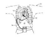
- FIG. 1is a diagram of a circulatory assist system as one example of an implantable pump employing the present invention.
- FIG. 2is a schematic diagram showing a ventricular assist system employing an H-bridge inverter and a controller.
- FIG. 3is a schematic diagram showing redundant phase legs and cable conductors employed in one embodiment of the present invention.
- FIG. 4is an equivalent circuit of lumped resistances and inductances modeling the cable and motor of the present invention.
- a patient 10is shown in fragmentary front elevational view.
- Surgically implanted either into the patient's abdominal cavity or pericardium 11is the pumping unit 12 of a ventricular assist device.
- An inflow conduit(on the hidden side of unit 12 ) pierces the heart to convey blood from the patient's left ventricle into pumping unit 12 .
- An outflow conduit 13conveys blood from pumping unit 12 to the patient's aorta.
- a subcutaneous power cable 14extends from pumping unit 12 outwardly of the patient's body via an incision to a compact control unit 15 worn by patient 10 .
- Control unit 15is powered by a main battery pack 16 and/or an external AC power supply and an internal backup battery.
- Cable 14is flexible in order to allow freedom of movement of the patient. Such movement, however, causes stresses to cable 14 and to its connections with pumping unit 12 and control unit 15 . To increase reliability and fault tolerance, the present invention uses redundant conductors in cable 14 to supply each of the phase currents that drive the pump motor.
- a conventional inverter and cabling for an LVAD systemis shown in FIG. 2 .
- a brushless DC motor in pump unit 12has phase windings 20 - 22 connected by cable 14 to an H-bridge inverter 23 .
- a controller 24such as a general purpose microcontroller, implements a field-oriented control (i.e., vector control) or other algorithm to determine proper energization of phase windings 20 - 22 to obtain the desired motor operation.
- Controller 24is connected to a driver 25 for generating drive signals coupled to the control inputs of individual switches (e.g., transistors) in inverter 23 .
- Controller 24has an input/output 26 for sending messages or generating fault alarms directed at the user or a physician, for example.
- Inverter 23has an H-bridge configuration with a first phase leg 30 , a second phase leg 31 , and a third phase leg 32 .
- Phase leg 30has an upper switch 33 and a lower switch 34 which are turned on and off by controller 24 via driver 25 as known in the art.
- a current sensor 35 in series with phase leg 30provides a measured current to controller 24 as an input to the vector control algorithm.
- phase leg 31includes switches 36 and 37 and a current sensor 38 .
- Phase leg 32includes switches 40 and 41 , but a current sensor may not be required since the vector control algorithm can infer a third current based on measured currents from sensors 35 and 38 .
- FIG. 3shows an improved ventricular assist system having higher reliability and fault tolerance as a result of redundant cable conductors and redundant phase legs. Controller 24 and driver 25 are modified for the redundancies and to perform additional fault detection functions as described below.
- An inverter 45is coupled by a redundant cable 46 to motor 47 in pump unit 12 .
- Inverter 45has a first phase 50 , a second phase 51 , and a third phase 52 .
- First phase 50has a first phase leg 55 and a second phase leg 56 .
- the upper and lower power switches in legs 55 and 56are respectively coupled together to provide synchronous operation of the legs.
- Respective conductors 57 and 58connect phase legs 55 and 56 to a connector terminal 60 .
- Cable 46includes conductors 61 and 62 connected at terminal 60 to conductors 57 and 58 , respectively. Conductors 61 and 62 are coupled to motor 47 via a terminal connector 63 in pump unit 12 . Redundant conductors 61 and 62 become interconnected within pump unit 12 in order to drive a respective winding of motor 47 .
- Legs 55 and 56include respective current sensors 64 and 65 measuring the separate current magnitudes flowing in each of legs 55 and 56 (which is also the current flowing in redundant conductors 57 and 58 , respectively). The measured currents are coupled to the controller for monitoring and motor control purposes as explained below. In addition to (or instead of) current, a different parameter of the electrical power utilization could be sensed, such as voltage.
- Phases 51 and 52 of inverter 45have an identical configuration.
- phase 51includes redundant phase legs 66 and 67 , which are independently connected to terminal 60 by conductors 68 and 69 .
- Corresponding conductors 70 and 71are provided in cable 46 .
- Current sensors 72 and 73provide measured currents for phase leg 66 and 67 to the controller.
- Phase 52includes legs 74 and 75 having their outputs connected to terminal 60 by conductors 76 and 77 .
- Cable 46includes conductors 78 and 79 which connect conductors 76 and 77 to pump unit terminal 63 .
- Phase 52includes current sensors 80 and 81 in legs 74 and 75 , respectively, which provide measured currents for legs 74 and 75 to the controller.
- the redundancy of the cable conductors, phase leg switches, and phase leg conductorsprovide fault tolerance whereby damage such as loss of continuity in one conductor or failure of one switch does not prevent operation of the ventricle assist system. Upon failure of one of these, the redundant conductor or phase leg carries the full current load instead of being distributed between the redundant elements, thereby providing continuous operation of the pump.
- Prior application Ser. No. 13/418,447discloses fault monitoring performed by comparing measured currents within redundant phase legs such that, if the currents are substantially equal (indicating that operation of electrical components is the same in each redundant leg) then conditions are nominal and no fault is detected. If the measured currents of a redundant conductor pair are substantially unequal, on the other hand, then a fault is detected. The fault occurrence may trigger an alarm to inform a user that steps should be taken to remedy the fault. However, regular pump operation is maintained by virtue of the redundant element continuing to supply the proper current to the motor.
- FIG. 4shows an equivalent circuit including a redundant cable 85 and pump motor 86 .
- a first redundant conductor pair 87is driven from an inverter leg A and is coupled to a first winding 90 .
- a second redundant conductor pair 88is driven from an inverter leg B and is coupled to a second winding 91 .
- a third redundant conductor pair 89is driven from an inverter leg C and is coupled to a third winding 92 .
- Windings 90 - 92are driven in pairs to provide the three phases of the motor operation, which may follow a field-oriented control algorithm.
- first conductor 93 of first pair 87power being utilized from leg A is sensed by a current sensor PC 1 (phase current 1 ) and/or a voltage sensor PV 1 (phase voltage 1 ).
- a current sensor PC 2phase current 2
- a voltage sensor PV 2phase voltage 2
- Conductors 93 and 94include wire resistances WR 1 and WR 2 which are both very small and about equal as long as there are no conductor failures.
- winding 90has an inductance L 1 .
- a corresponding coil resistance CR 1is likewise small as long as there are no component failures within motor 86 associated with winding 90 .
- Second and third conductor pairs 88 and 89include similar sensors and resistances, as indicated using consistent notations.
- Second winding 91has an inductance L 2 and associated coil resistance CR 2 .
- Third winding 92has an inductance L 3 and associated coil resistance CR 3 .
- inductances L 1 -L 3 and resistances CR 1 -CR 3are each about equal. Therefore, any chosen power utilization parameter that is monitored from cycle to cycle of motor operation will be about the same from phase to phase when no faults are present. By checking for differences (i.e., imbalances) from phase to phase, a fault can be detected using the present invention.
- coil resistance CR 1begins to increase (e.g., resulting from a soldering terminal issue, wire breakage, or substrate damage)
- current for the phases in which winding 90 is energizedwill begin to decrease compared to the other phases.
- inductance L 1begins to decrease (e.g., resulting from a shorted turn in the coil or a detachment of the core/yoke) then a phase voltage may decrease as compared to the other phases.
- the illustrated embodiment of the present invention with redundant cablingadapts the motor controller to perform the steps of 1) switching the H-bridge inverter in a sequence for operating the motor, 2) characterizing a first power utilization parameter of one of the conductor pairs during energization of the first phase, 3) characterizing a second power utilization parameter of one of the conductor pairs during energization of the second phase, 4) characterizing a third power utilization parameter of one of the conductor pairs during energization of the third phase, and 5) pairwise comparing the power utilization parameters and detecting a fault in the implantable pump in response to an imbalance of one of the comparisons. If redundant cable pairs are not present, then each power utilization parameter would depend on just one conductor.
- the pairwise comparisonsinclude detecting a fault in response to the condition:
- P Ais the power utilization parameter of the first phase
- P Bis the power utilization parameter of the second phase
- cis a predetermined constant.
- the magnitude of constant cis preferably selected to provide early detection of degrading conditions while avoiding false alarms. The occurrence of the fault is reported to the user so that it can be corrected.
- the pairwise comparisonsfurther include detecting a fault in response to the conditions:
- the sequence for operating the motor as generated by the H-bridge inverterincludes a continuous succession of respective cycles for all the phases.
- the power utilization parameterscharacterize the current or voltage measurement of each respective phase over at least one cycle. Measurement for one phase is conducted closely in time to the measurements for the other phases. To characterize any particular cycle, the measurement may be comprised of a peak-to-peak value or an RMS value, for example.
- a power utilization parameteris comprised of current measurements then the currents within each respective conductor pair are preferably added together, and the resulting sum is used for the comparisons.
- a power utilization parameteris comprised of voltage measurements then an average of the two voltages at the conductors within a respective conductor pair can be used.
Landscapes
- Health & Medical Sciences (AREA)
- Engineering & Computer Science (AREA)
- Heart & Thoracic Surgery (AREA)
- Cardiology (AREA)
- Life Sciences & Earth Sciences (AREA)
- Anesthesiology (AREA)
- Biomedical Technology (AREA)
- Hematology (AREA)
- Mechanical Engineering (AREA)
- Animal Behavior & Ethology (AREA)
- General Health & Medical Sciences (AREA)
- Public Health (AREA)
- Veterinary Medicine (AREA)
- Computer Networks & Wireless Communication (AREA)
- Medical Informatics (AREA)
- External Artificial Organs (AREA)
Abstract
Description
|PA−PB|>c
where PAis the power utilization parameter of the first phase, PBis the power utilization parameter of the second phase, and c is a predetermined constant. Thus, if the absolute difference between the currents or voltages present in different phases is greater than the predetermined constant then a fault is detected. The magnitude of constant c is preferably selected to provide early detection of degrading conditions while avoiding false alarms. The occurrence of the fault is reported to the user so that it can be corrected. For completeness, the pairwise comparisons further include detecting a fault in response to the conditions:
|PB−PC|>c, and
|PA−PC|>c
where PCis the power utilization parameter of the third phase.
Claims (17)
|PA−PB|>c
|PB−PC|>c
|PA−PC|>c.
|PA−PB|>c
|PB−PCT>c
|PA−PC|>c.
Priority Applications (3)
| Application Number | Priority Date | Filing Date | Title |
|---|---|---|---|
| US13/742,469US8968174B2 (en) | 2013-01-16 | 2013-01-16 | Motor fault monitor for implantable blood pump |
| EP14741174.8AEP2945662B1 (en) | 2013-01-16 | 2014-01-16 | Motor fault monitor for implantable blood pump |
| PCT/US2014/011786WO2014113533A1 (en) | 2013-01-16 | 2014-01-16 | Motor fault monitor for implantable blood pump |
Applications Claiming Priority (1)
| Application Number | Priority Date | Filing Date | Title |
|---|---|---|---|
| US13/742,469US8968174B2 (en) | 2013-01-16 | 2013-01-16 | Motor fault monitor for implantable blood pump |
Publications (2)
| Publication Number | Publication Date |
|---|---|
| US20140200389A1 US20140200389A1 (en) | 2014-07-17 |
| US8968174B2true US8968174B2 (en) | 2015-03-03 |
Family
ID=51165634
Family Applications (1)
| Application Number | Title | Priority Date | Filing Date |
|---|---|---|---|
| US13/742,469Expired - Fee RelatedUS8968174B2 (en) | 2013-01-16 | 2013-01-16 | Motor fault monitor for implantable blood pump |
Country Status (3)
| Country | Link |
|---|---|
| US (1) | US8968174B2 (en) |
| EP (1) | EP2945662B1 (en) |
| WO (1) | WO2014113533A1 (en) |
Cited By (12)
| Publication number | Priority date | Publication date | Assignee | Title |
|---|---|---|---|---|
| US9556873B2 (en) | 2013-02-27 | 2017-01-31 | Tc1 Llc | Startup sequence for centrifugal pump with levitated impeller |
| US9623161B2 (en) | 2014-08-26 | 2017-04-18 | Tc1 Llc | Blood pump and method of suction detection |
| US9638202B2 (en) | 2010-09-14 | 2017-05-02 | Tc1 Llc | Centrifugal pump apparatus |
| US9709061B2 (en) | 2013-01-24 | 2017-07-18 | Tc1 Llc | Impeller position compensation using field oriented control |
| US9850906B2 (en) | 2011-03-28 | 2017-12-26 | Tc1 Llc | Rotation drive device and centrifugal pump apparatus employing same |
| US10052420B2 (en) | 2013-04-30 | 2018-08-21 | Tc1 Llc | Heart beat identification and pump speed synchronization |
| US10117983B2 (en) | 2015-11-16 | 2018-11-06 | Tc1 Llc | Pressure/flow characteristic modification of a centrifugal pump in a ventricular assist device |
| US10166318B2 (en) | 2015-02-12 | 2019-01-01 | Tc1 Llc | System and method for controlling the position of a levitated rotor |
| US10245361B2 (en) | 2015-02-13 | 2019-04-02 | Tc1 Llc | Impeller suspension mechanism for heart pump |
| US10371152B2 (en) | 2015-02-12 | 2019-08-06 | Tc1 Llc | Alternating pump gaps |
| US10413649B2 (en) | 2014-10-01 | 2019-09-17 | Heartware, Inc. | Back up controller system with updating |
| US10506935B2 (en) | 2015-02-11 | 2019-12-17 | Tc1 Llc | Heart beat identification and pump speed synchronization |
Families Citing this family (39)
| Publication number | Priority date | Publication date | Assignee | Title |
|---|---|---|---|---|
| US9192705B2 (en)* | 2013-03-25 | 2015-11-24 | Thoratec Corporation | Percutaneous cable with redundant conductors for implantable blood pump |
| WO2015183922A1 (en)* | 2014-05-27 | 2015-12-03 | Mayo Foundation For Medical Education And Research | Application-based mechanical circulatory support device assessments |
| EP3490629B1 (en)* | 2016-08-01 | 2020-05-13 | Heartware, Inc. | Heart rate determination based on vad current waveform |
| CN109789258A (en)* | 2016-09-23 | 2019-05-21 | 心脏器械股份有限公司 | For controlling the Field orientable control of blood pump motor |
| ES2856975T3 (en)* | 2017-02-07 | 2021-09-28 | Abiomed Europe Gmbh | Blood pump |
| CA3066361A1 (en) | 2017-06-07 | 2018-12-13 | Shifamed Holdings, Llc | Intravascular fluid movement devices, systems, and methods of use |
| WO2019094963A1 (en) | 2017-11-13 | 2019-05-16 | Shifamed Holdings, Llc | Intravascular fluid movement devices, systems, and methods of use |
| DE102018201030B4 (en) | 2018-01-24 | 2025-10-16 | Kardion Gmbh | Magnetic dome element with magnetic bearing function |
| CN112004563B (en) | 2018-02-01 | 2024-08-06 | 施菲姆德控股有限责任公司 | Intravascular blood pump and methods of use and manufacture |
| DE102018207575A1 (en) | 2018-05-16 | 2019-11-21 | Kardion Gmbh | Magnetic face turning coupling for the transmission of torques |
| DE102018207611A1 (en) | 2018-05-16 | 2019-11-21 | Kardion Gmbh | Rotor bearing system |
| DE102018208539A1 (en) | 2018-05-30 | 2019-12-05 | Kardion Gmbh | A motor housing module for sealing an engine compartment of a motor of a cardiac assist system and cardiac assistance system and method for mounting a cardiac assist system |
| DE102018208538A1 (en) | 2018-05-30 | 2019-12-05 | Kardion Gmbh | Intravascular blood pump and process for the production of electrical conductors |
| DE102018208541A1 (en) | 2018-05-30 | 2019-12-05 | Kardion Gmbh | Axial pump for a cardiac assist system and method of making an axial pump for a cardiac assist system |
| DE102018208550A1 (en) | 2018-05-30 | 2019-12-05 | Kardion Gmbh | A lead device for directing blood flow to a cardiac assist system, cardiac assist system, and method of making a lead device |
| DE102018208929A1 (en) | 2018-06-06 | 2019-12-12 | Kardion Gmbh | A method of determining a flow rate of fluid flowing through an implanted vascular support system |
| DE102018208933A1 (en) | 2018-06-06 | 2019-12-12 | Kardion Gmbh | A method of determining a flow rate of fluid flowing through an implanted vascular support system |
| DE102018208913A1 (en) | 2018-06-06 | 2019-12-12 | Kardion Gmbh | A method of operating an implanted ventricular assist device |
| DE102018208879A1 (en) | 2018-06-06 | 2020-01-30 | Kardion Gmbh | Method for determining a total fluid volume flow in the area of an implanted, vascular support system |
| DE102018208862A1 (en) | 2018-06-06 | 2019-12-12 | Kardion Gmbh | Implantable vascular support system |
| DE102018208936A1 (en) | 2018-06-06 | 2019-12-12 | Kardion Gmbh | Determining device and method for determining a viscosity of a fluid |
| DE102018208945A1 (en) | 2018-06-06 | 2019-12-12 | Kardion Gmbh | An analysis device and method for analyzing a viscosity of a fluid |
| DE102018208899A1 (en) | 2018-06-06 | 2019-12-12 | Kardion Gmbh | A method for determining the speed of sound in a fluid in the region of an implanted vascular support system |
| DE102018210058A1 (en) | 2018-06-21 | 2019-12-24 | Kardion Gmbh | Stator blade device for guiding the flow of a fluid flowing out of an outlet opening of a heart support system, heart support system with stator blade device, method for operating a stator blade device and manufacturing method |
| DE102018210076A1 (en)* | 2018-06-21 | 2019-12-24 | Kardion Gmbh | Method and device for detecting a state of wear of a cardiac support system, method and device for operating a cardiac support system and cardiac support system |
| DE102018211327A1 (en) | 2018-07-10 | 2020-01-16 | Kardion Gmbh | Impeller for an implantable vascular support system |
| DE102018212153A1 (en) | 2018-07-20 | 2020-01-23 | Kardion Gmbh | Inlet line for a pump unit of a cardiac support system, cardiac support system and method for producing an inlet line for a pump unit of a cardiac support system |
| US12161857B2 (en) | 2018-07-31 | 2024-12-10 | Shifamed Holdings, Llc | Intravascular blood pumps and methods of use |
| CN112654389A (en) | 2018-08-07 | 2021-04-13 | 开迪恩有限公司 | Bearing device for a cardiac support system and method for flushing an intermediate space in a bearing device for a cardiac support system |
| WO2020073047A1 (en) | 2018-10-05 | 2020-04-09 | Shifamed Holdings, Llc | Intravascular blood pumps and methods of use |
| WO2021011473A1 (en) | 2019-07-12 | 2021-01-21 | Shifamed Holdings, Llc | Intravascular blood pumps and methods of manufacture and use |
| US11654275B2 (en) | 2019-07-22 | 2023-05-23 | Shifamed Holdings, Llc | Intravascular blood pumps with struts and methods of use and manufacture |
| WO2021062265A1 (en) | 2019-09-25 | 2021-04-01 | Shifamed Holdings, Llc | Intravascular blood pump systems and methods of use and control thereof |
| US12121713B2 (en) | 2019-09-25 | 2024-10-22 | Shifamed Holdings, Llc | Catheter blood pumps and collapsible blood conduits |
| EP4501393A3 (en) | 2019-09-25 | 2025-04-09 | Shifamed Holdings, LLC | Catheter blood pumps and collapsible pump housings |
| EP4048367B1 (en)* | 2019-10-25 | 2025-04-23 | Tc1 Llc | Circulatory support systems including controller and plurality of sensors |
| WO2021099824A1 (en) | 2019-11-22 | 2021-05-27 | Cummins Inc. | Fault tolerant inverter for partial phase loss in multi-phase machines |
| EP4072650A4 (en) | 2019-12-11 | 2024-01-10 | Shifamed Holdings, LLC | Descending aorta and vena cava blood pumps |
| DE102020102474A1 (en) | 2020-01-31 | 2021-08-05 | Kardion Gmbh | Pump for conveying a fluid and method for manufacturing a pump |
Citations (20)
| Publication number | Priority date | Publication date | Assignee | Title |
|---|---|---|---|---|
| US4434389A (en)* | 1980-10-28 | 1984-02-28 | Kollmorgen Technologies Corporation | Motor with redundant windings |
| WO1994014226A1 (en) | 1992-12-14 | 1994-06-23 | Honeywell Inc. | Motor system with individually controlled redundant windings |
| US5613935A (en) | 1994-12-16 | 1997-03-25 | Jarvik; Robert | High reliability cardiac assist system |
| US5630836A (en) | 1995-01-19 | 1997-05-20 | Vascor, Inc. | Transcutaneous energy and information transmission apparatus |
| US5843129A (en) | 1992-08-06 | 1998-12-01 | Electric Boat Corporation | Electrical circuit for equipment requiring redundant flow paths and method of use |
| US5917295A (en) | 1996-01-31 | 1999-06-29 | Kaman Electromagnetics Corporation | Motor drive system having a plurality of series connected H-bridges |
| US6149683A (en) | 1998-10-05 | 2000-11-21 | Kriton Medical, Inc. | Power system for an implantable heart pump |
| US6320731B1 (en) | 2000-05-24 | 2001-11-20 | Electric Boat Corporation | Fault tolerant motor drive arrangement with independent phase connections and monitoring system |
| US6351048B1 (en) | 1999-06-22 | 2002-02-26 | Levitronix Llc | Electrical rotary drive |
| US6605032B2 (en) | 1997-10-02 | 2003-08-12 | Micromed Technology, Inc. | Implantable pump system |
| US20040145337A1 (en) | 2003-01-24 | 2004-07-29 | Toshiba Internatioal Corporation | Inverter drive system |
| US20040263341A1 (en) | 2003-06-24 | 2004-12-30 | Enzinna Donald John | Airflow blockage detection apparatus for a permanent split-capacitor single-phase fan motor |
| US20050073273A1 (en) | 2003-10-06 | 2005-04-07 | Wavecrest Laboratories, Llc | Fault-tolerant electric motor control system |
| US20080007196A1 (en) | 2006-06-22 | 2008-01-10 | Daisuke Tan | Apparatus and method for driving an induction motor |
| US20080211439A1 (en) | 2007-02-15 | 2008-09-04 | Denso Corporation | Drive device for a brushless motor |
| US7660635B1 (en) | 1996-12-19 | 2010-02-09 | Medtronic, Inc. | Medical electrical lead |
| US20100305692A1 (en) | 2009-05-27 | 2010-12-02 | Thomas Douglas C | Monitoring of redundant conductors |
| US20110015732A1 (en) | 2008-03-25 | 2011-01-20 | Sun Medical Technology Research Corporation | Auxiliary artificial heart pump drive device and auxiliary artifical heart system |
| US20110218383A1 (en) | 2010-03-05 | 2011-09-08 | Minnetronix Inc. | Portable controller and power source for mechanical circulation support systems |
| US20130289334A1 (en)* | 2011-07-11 | 2013-10-31 | Kurt D. Badstibner | Transcutaneous power transmission and communication for implanted heart assist and other devices |
- 2013
- 2013-01-16USUS13/742,469patent/US8968174B2/ennot_activeExpired - Fee Related
- 2014
- 2014-01-16EPEP14741174.8Apatent/EP2945662B1/ennot_activeNot-in-force
- 2014-01-16WOPCT/US2014/011786patent/WO2014113533A1/enactiveApplication Filing
Patent Citations (22)
| Publication number | Priority date | Publication date | Assignee | Title |
|---|---|---|---|---|
| US4434389A (en)* | 1980-10-28 | 1984-02-28 | Kollmorgen Technologies Corporation | Motor with redundant windings |
| US5843129A (en) | 1992-08-06 | 1998-12-01 | Electric Boat Corporation | Electrical circuit for equipment requiring redundant flow paths and method of use |
| WO1994014226A1 (en) | 1992-12-14 | 1994-06-23 | Honeywell Inc. | Motor system with individually controlled redundant windings |
| US5613935A (en) | 1994-12-16 | 1997-03-25 | Jarvik; Robert | High reliability cardiac assist system |
| US5630836A (en) | 1995-01-19 | 1997-05-20 | Vascor, Inc. | Transcutaneous energy and information transmission apparatus |
| US5917295A (en) | 1996-01-31 | 1999-06-29 | Kaman Electromagnetics Corporation | Motor drive system having a plurality of series connected H-bridges |
| US7660635B1 (en) | 1996-12-19 | 2010-02-09 | Medtronic, Inc. | Medical electrical lead |
| US6605032B2 (en) | 1997-10-02 | 2003-08-12 | Micromed Technology, Inc. | Implantable pump system |
| US6149683A (en) | 1998-10-05 | 2000-11-21 | Kriton Medical, Inc. | Power system for an implantable heart pump |
| US6351048B1 (en) | 1999-06-22 | 2002-02-26 | Levitronix Llc | Electrical rotary drive |
| US6320731B1 (en) | 2000-05-24 | 2001-11-20 | Electric Boat Corporation | Fault tolerant motor drive arrangement with independent phase connections and monitoring system |
| US20040145337A1 (en) | 2003-01-24 | 2004-07-29 | Toshiba Internatioal Corporation | Inverter drive system |
| US20040263341A1 (en) | 2003-06-24 | 2004-12-30 | Enzinna Donald John | Airflow blockage detection apparatus for a permanent split-capacitor single-phase fan motor |
| US20050073273A1 (en) | 2003-10-06 | 2005-04-07 | Wavecrest Laboratories, Llc | Fault-tolerant electric motor control system |
| US20080007196A1 (en) | 2006-06-22 | 2008-01-10 | Daisuke Tan | Apparatus and method for driving an induction motor |
| US20080211439A1 (en) | 2007-02-15 | 2008-09-04 | Denso Corporation | Drive device for a brushless motor |
| US20110015732A1 (en) | 2008-03-25 | 2011-01-20 | Sun Medical Technology Research Corporation | Auxiliary artificial heart pump drive device and auxiliary artifical heart system |
| US20100305692A1 (en) | 2009-05-27 | 2010-12-02 | Thomas Douglas C | Monitoring of redundant conductors |
| US20110218383A1 (en) | 2010-03-05 | 2011-09-08 | Minnetronix Inc. | Portable controller and power source for mechanical circulation support systems |
| US20110218385A1 (en) | 2010-03-05 | 2011-09-08 | Minnetronix Inc. | Portable controller with integral power source for mechanical circulation support systems |
| US20110218384A1 (en) | 2010-03-05 | 2011-09-08 | Minnetronix Inc. | Portable controller with integral power source for mechanical circulation support systems |
| US20130289334A1 (en)* | 2011-07-11 | 2013-10-31 | Kurt D. Badstibner | Transcutaneous power transmission and communication for implanted heart assist and other devices |
Non-Patent Citations (1)
| Title |
|---|
| International Search Report and Written Opinion in PCT/US2014/011786 mailed on May 5, 2014, 11 pages. |
Cited By (23)
| Publication number | Priority date | Publication date | Assignee | Title |
|---|---|---|---|---|
| US9638202B2 (en) | 2010-09-14 | 2017-05-02 | Tc1 Llc | Centrifugal pump apparatus |
| US9850906B2 (en) | 2011-03-28 | 2017-12-26 | Tc1 Llc | Rotation drive device and centrifugal pump apparatus employing same |
| US9709061B2 (en) | 2013-01-24 | 2017-07-18 | Tc1 Llc | Impeller position compensation using field oriented control |
| US9556873B2 (en) | 2013-02-27 | 2017-01-31 | Tc1 Llc | Startup sequence for centrifugal pump with levitated impeller |
| US10052420B2 (en) | 2013-04-30 | 2018-08-21 | Tc1 Llc | Heart beat identification and pump speed synchronization |
| US9623161B2 (en) | 2014-08-26 | 2017-04-18 | Tc1 Llc | Blood pump and method of suction detection |
| US10413649B2 (en) | 2014-10-01 | 2019-09-17 | Heartware, Inc. | Back up controller system with updating |
| US10506935B2 (en) | 2015-02-11 | 2019-12-17 | Tc1 Llc | Heart beat identification and pump speed synchronization |
| US12213766B2 (en) | 2015-02-11 | 2025-02-04 | Tc1 Llc | Heart beat identification and pump speed synchronization |
| US11712167B2 (en) | 2015-02-11 | 2023-08-01 | Tc1 Llc | Heart beat identification and pump speed synchronization |
| US10856748B2 (en) | 2015-02-11 | 2020-12-08 | Tc1 Llc | Heart beat identification and pump speed synchronization |
| US11015605B2 (en) | 2015-02-12 | 2021-05-25 | Tc1 Llc | Alternating pump gaps |
| US10874782B2 (en) | 2015-02-12 | 2020-12-29 | Tc1 Llc | System and method for controlling the position of a levitated rotor |
| US10166318B2 (en) | 2015-02-12 | 2019-01-01 | Tc1 Llc | System and method for controlling the position of a levitated rotor |
| US10371152B2 (en) | 2015-02-12 | 2019-08-06 | Tc1 Llc | Alternating pump gaps |
| US11724097B2 (en) | 2015-02-12 | 2023-08-15 | Tc1 Llc | System and method for controlling the position of a levitated rotor |
| US11781551B2 (en) | 2015-02-12 | 2023-10-10 | Tc1 Llc | Alternating pump gaps |
| US12285598B2 (en) | 2015-02-12 | 2025-04-29 | Tc1 Llc | System and method for controlling the position of a levitated rotor |
| US12297836B2 (en) | 2015-02-12 | 2025-05-13 | Tc1 Llc | Alternating pump gaps |
| US10245361B2 (en) | 2015-02-13 | 2019-04-02 | Tc1 Llc | Impeller suspension mechanism for heart pump |
| US10117983B2 (en) | 2015-11-16 | 2018-11-06 | Tc1 Llc | Pressure/flow characteristic modification of a centrifugal pump in a ventricular assist device |
| US10888645B2 (en) | 2015-11-16 | 2021-01-12 | Tc1 Llc | Pressure/flow characteristic modification of a centrifugal pump in a ventricular assist device |
| US11639722B2 (en) | 2015-11-16 | 2023-05-02 | Tc1 Llc | Pressure/flow characteristic modification of a centrifugal pump in a ventricular assist device |
Also Published As
| Publication number | Publication date |
|---|---|
| EP2945662A4 (en) | 2016-10-12 |
| US20140200389A1 (en) | 2014-07-17 |
| EP2945662A1 (en) | 2015-11-25 |
| EP2945662B1 (en) | 2018-04-04 |
| WO2014113533A1 (en) | 2014-07-24 |
Similar Documents
| Publication | Publication Date | Title |
|---|---|---|
| US8968174B2 (en) | Motor fault monitor for implantable blood pump | |
| US8837096B2 (en) | Fault monitor for fault tolerant implantable pump | |
| JP7734726B2 (en) | blood pump | |
| US9192705B2 (en) | Percutaneous cable with redundant conductors for implantable blood pump | |
| US10773003B2 (en) | System architecture that allows patient replacement of VAD controller/interface module without disconnection of old module | |
| US10722632B2 (en) | Blood pump controllers and methods of use for improved energy efficiency | |
| CN111757761A (en) | Axial Pump Pressure Algorithm with Field Oriented Control | |
| WO2018057608A1 (en) | Field-oriented control for control of blood pump motor | |
| TW201219071A (en) | Controlling implanted blood pumps | |
| JP2025519366A (en) | Blood Pump Controllers and Systems | |
| CN118631129A (en) | Fault handling method and device for ventricular assist device | |
| CN119448881A (en) | Motor fault processing method, control unit, ventricular assist device and medical equipment |
Legal Events
| Date | Code | Title | Description |
|---|---|---|---|
| AS | Assignment | Owner name:TERUMO KABUSHIKI KAISHA, MICHIGAN Free format text:ASSIGNMENT OF ASSIGNORS INTEREST;ASSIGNORS:YANAI, MASAMICHI;ZHANG, TAO;SIGNING DATES FROM 20130110 TO 20130114;REEL/FRAME:029637/0081 | |
| AS | Assignment | Owner name:THORATEC CORPORATION, CALIFORNIA Free format text:ASSIGNMENT OF ASSIGNORS INTEREST;ASSIGNOR:TERUMO KABUSHIKI KAISHA;REEL/FRAME:031016/0364 Effective date:20130630 | |
| STCF | Information on status: patent grant | Free format text:PATENTED CASE | |
| AS | Assignment | Owner name:THORATEC LLC, CALIFORNIA Free format text:CHANGE OF NAME;ASSIGNOR:THORATEC CORPORATION;REEL/FRAME:041428/0327 Effective date:20151112 Owner name:TC1 LLC, CALIFORNIA Free format text:ASSIGNMENT OF ASSIGNORS INTEREST;ASSIGNOR:THORATEC LLC;REEL/FRAME:041428/0685 Effective date:20161114 | |
| MAFP | Maintenance fee payment | Free format text:PAYMENT OF MAINTENANCE FEE, 4TH YEAR, LARGE ENTITY (ORIGINAL EVENT CODE: M1551); ENTITY STATUS OF PATENT OWNER: LARGE ENTITY Year of fee payment:4 | |
| FEPP | Fee payment procedure | Free format text:MAINTENANCE FEE REMINDER MAILED (ORIGINAL EVENT CODE: REM.); ENTITY STATUS OF PATENT OWNER: LARGE ENTITY | |
| LAPS | Lapse for failure to pay maintenance fees | Free format text:PATENT EXPIRED FOR FAILURE TO PAY MAINTENANCE FEES (ORIGINAL EVENT CODE: EXP.); ENTITY STATUS OF PATENT OWNER: LARGE ENTITY | |
| STCH | Information on status: patent discontinuation | Free format text:PATENT EXPIRED DUE TO NONPAYMENT OF MAINTENANCE FEES UNDER 37 CFR 1.362 | |
| FP | Lapsed due to failure to pay maintenance fee | Effective date:20230303 |