US8963845B2 - Mobile device with temperature sensing capability and method of operating same - Google Patents
Mobile device with temperature sensing capability and method of operating sameDownload PDFInfo
- Publication number
- US8963845B2 US8963845B2US12/774,509US77450910AUS8963845B2US 8963845 B2US8963845 B2US 8963845B2US 77450910 AUS77450910 AUS 77450910AUS 8963845 B2US8963845 B2US 8963845B2
- Authority
- US
- United States
- Prior art keywords
- mobile device
- electronic device
- temperature sensing
- temperature
- sensing devices
- Prior art date
- Legal status (The legal status is an assumption and is not a legal conclusion. Google has not performed a legal analysis and makes no representation as to the accuracy of the status listed.)
- Active, expires
Links
- 238000000034methodMethods0.000titleabstractdescription38
- 238000012545processingMethods0.000claimsabstractdescription14
- 238000002955isolationMethods0.000claimsdescription8
- 238000005259measurementMethods0.000claimsdescription2
- 238000004220aggregationMethods0.000claims1
- 230000002776aggregationEffects0.000claims1
- 230000008569processEffects0.000description27
- 238000004891communicationMethods0.000description26
- 230000009471actionEffects0.000description18
- OKTJSMMVPCPJKN-UHFFFAOYSA-NCarbonChemical compound[C]OKTJSMMVPCPJKN-UHFFFAOYSA-N0.000description17
- 229910002804graphiteInorganic materials0.000description17
- 239000010439graphiteSubstances0.000description17
- 230000006870functionEffects0.000description9
- 230000033001locomotionEffects0.000description9
- 239000011572manganeseSubstances0.000description8
- 230000004044responseEffects0.000description8
- 230000001953sensory effectEffects0.000description8
- 238000005516engineering processMethods0.000description7
- 239000000463materialSubstances0.000description6
- 229910052751metalInorganic materials0.000description6
- 239000002184metalSubstances0.000description6
- RYGMFSIKBFXOCR-UHFFFAOYSA-NCopperChemical compound[Cu]RYGMFSIKBFXOCR-UHFFFAOYSA-N0.000description4
- 230000001413cellular effectEffects0.000description4
- 239000004020conductorSubstances0.000description4
- 229910052802copperInorganic materials0.000description4
- 239000010949copperSubstances0.000description4
- 238000001514detection methodMethods0.000description4
- 238000010586diagramMethods0.000description4
- 230000000007visual effectEffects0.000description4
- 230000000284resting effectEffects0.000description3
- 230000001133accelerationEffects0.000description2
- 239000000654additiveSubstances0.000description2
- 230000000996additive effectEffects0.000description2
- 229910010293ceramic materialInorganic materials0.000description2
- 239000011248coating agentSubstances0.000description2
- 238000000576coating methodMethods0.000description2
- 230000000694effectsEffects0.000description2
- 239000011521glassSubstances0.000description2
- 238000010438heat treatmentMethods0.000description2
- 230000007246mechanismEffects0.000description2
- 150000002739metalsChemical class0.000description2
- 230000003287optical effectEffects0.000description2
- 230000003014reinforcing effectEffects0.000description2
- 230000029058respiratory gaseous exchangeEffects0.000description2
- 238000012360testing methodMethods0.000description2
- IRLPACMLTUPBCL-KQYNXXCUSA-N5'-adenylyl sulfateChemical compoundC1=NC=2C(N)=NC=NC=2N1[C@@H]1O[C@H](COP(O)(=O)OS(O)(=O)=O)[C@@H](O)[C@H]1OIRLPACMLTUPBCL-KQYNXXCUSA-N0.000description1
- BQCADISMDOOEFD-UHFFFAOYSA-NSilverChemical compound[Ag]BQCADISMDOOEFD-UHFFFAOYSA-N0.000description1
- 229910052782aluminiumInorganic materials0.000description1
- XAGFODPZIPBFFR-UHFFFAOYSA-NaluminiumChemical compound[Al]XAGFODPZIPBFFR-UHFFFAOYSA-N0.000description1
- 230000009118appropriate responseEffects0.000description1
- 230000000712assemblyEffects0.000description1
- 238000000429assemblyMethods0.000description1
- 230000006399behaviorEffects0.000description1
- 230000008901benefitEffects0.000description1
- 230000005540biological transmissionEffects0.000description1
- 230000015572biosynthetic processEffects0.000description1
- 238000009529body temperature measurementMethods0.000description1
- 230000008859changeEffects0.000description1
- 230000003111delayed effectEffects0.000description1
- 238000011161developmentMethods0.000description1
- 230000018109developmental processEffects0.000description1
- 229910003460diamondInorganic materials0.000description1
- 239000010432diamondSubstances0.000description1
- 238000001914filtrationMethods0.000description1
- 229920002457flexible plasticPolymers0.000description1
- 238000007667floatingMethods0.000description1
- MHMNJMPURVTYEJ-UHFFFAOYSA-Nfluorescein-5-isothiocyanateChemical compoundO1C(=O)C2=CC(N=C=S)=CC=C2C21C1=CC=C(O)C=C1OC1=CC(O)=CC=C21MHMNJMPURVTYEJ-UHFFFAOYSA-N0.000description1
- 230000006266hibernationEffects0.000description1
- 230000006872improvementEffects0.000description1
- NLHUEOQYIDKBSL-UHFFFAOYSA-Nindium;manganese;oxotinChemical compound[Mn].[In].[Sn]=ONLHUEOQYIDKBSL-UHFFFAOYSA-N0.000description1
- AMGQUBHHOARCQH-UHFFFAOYSA-Nindium;oxotinChemical compound[In].[Sn]=OAMGQUBHHOARCQH-UHFFFAOYSA-N0.000description1
- 230000003993interactionEffects0.000description1
- 239000004973liquid crystal related substanceSubstances0.000description1
- 238000000465mouldingMethods0.000description1
- 229920003023plasticPolymers0.000description1
- 238000003825pressingMethods0.000description1
- 230000009467reductionEffects0.000description1
- 230000003252repetitive effectEffects0.000description1
- 238000011160researchMethods0.000description1
- 229910052709silverInorganic materials0.000description1
- 239000004332silverSubstances0.000description1
- 230000007958sleepEffects0.000description1
- 238000005476solderingMethods0.000description1
- 230000003068static effectEffects0.000description1
- 238000012546transferMethods0.000description1
- 238000003466weldingMethods0.000description1
Images


Classifications
- H—ELECTRICITY
- H04—ELECTRIC COMMUNICATION TECHNIQUE
- H04M—TELEPHONIC COMMUNICATION
- H04M1/00—Substation equipment, e.g. for use by subscribers
- H04M1/72—Mobile telephones; Cordless telephones, i.e. devices for establishing wireless links to base stations without route selection
- H04M1/724—User interfaces specially adapted for cordless or mobile telephones
- H04M1/72448—User interfaces specially adapted for cordless or mobile telephones with means for adapting the functionality of the device according to specific conditions
- H04M1/72454—User interfaces specially adapted for cordless or mobile telephones with means for adapting the functionality of the device according to specific conditions according to context-related or environment-related conditions
- H04M1/72569—
- H—ELECTRICITY
- H04—ELECTRIC COMMUNICATION TECHNIQUE
- H04M—TELEPHONIC COMMUNICATION
- H04M2250/00—Details of telephonic subscriber devices
- H04M2250/12—Details of telephonic subscriber devices including a sensor for measuring a physical value, e.g. temperature or motion
- H—ELECTRICITY
- H04—ELECTRIC COMMUNICATION TECHNIQUE
- H04W—WIRELESS COMMUNICATION NETWORKS
- H04W52/00—Power management, e.g. Transmission Power Control [TPC] or power classes
- H04W52/02—Power saving arrangements
- H04W52/0209—Power saving arrangements in terminal devices
- H04W52/0261—Power saving arrangements in terminal devices managing power supply demand, e.g. depending on battery level
- H04W52/0267—Power saving arrangements in terminal devices managing power supply demand, e.g. depending on battery level by controlling user interface components
- H04W52/027—Power saving arrangements in terminal devices managing power supply demand, e.g. depending on battery level by controlling user interface components by controlling a display operation or backlight unit
- H—ELECTRICITY
- H04—ELECTRIC COMMUNICATION TECHNIQUE
- H04W—WIRELESS COMMUNICATION NETWORKS
- H04W52/00—Power management, e.g. Transmission Power Control [TPC] or power classes
- H04W52/02—Power saving arrangements
- H04W52/0209—Power saving arrangements in terminal devices
- H04W52/0261—Power saving arrangements in terminal devices managing power supply demand, e.g. depending on battery level
- H04W52/0274—Power saving arrangements in terminal devices managing power supply demand, e.g. depending on battery level by switching on or off the equipment or parts thereof
- Y—GENERAL TAGGING OF NEW TECHNOLOGICAL DEVELOPMENTS; GENERAL TAGGING OF CROSS-SECTIONAL TECHNOLOGIES SPANNING OVER SEVERAL SECTIONS OF THE IPC; TECHNICAL SUBJECTS COVERED BY FORMER USPC CROSS-REFERENCE ART COLLECTIONS [XRACs] AND DIGESTS
- Y02—TECHNOLOGIES OR APPLICATIONS FOR MITIGATION OR ADAPTATION AGAINST CLIMATE CHANGE
- Y02D—CLIMATE CHANGE MITIGATION TECHNOLOGIES IN INFORMATION AND COMMUNICATION TECHNOLOGIES [ICT], I.E. INFORMATION AND COMMUNICATION TECHNOLOGIES AIMING AT THE REDUCTION OF THEIR OWN ENERGY USE
- Y02D30/00—Reducing energy consumption in communication networks
- Y02D30/70—Reducing energy consumption in communication networks in wireless communication networks
Definitions
- the present inventionrelates generally to mobile devices and, more particularly, to mobile devices with component(s) allowing for the mobile devices to have temperature sensing capabilities, as well as to methods of operating such mobile devices.
- Mobile devicessuch as cellular telephones, smart phones and other handheld or portable electronic devices such as personal digital assistants (PDAs), headsets, MP3 players, etc. have become popular and ubiquitous.
- PDAspersonal digital assistants
- Such mobile devicesnow often include numerous different types of input devices and/or sensors that allow for the mobile device to sense/receive signals indicative of a variety of user commands and/or operational conditions.
- many mobile devicesnow include not merely buttons that can be pressed by a user, but also input devices such as touch sensitive screens or navigation devices.
- many mobile devicesnow include other sensors such as sensors that can detect incoming light signals such as infrared signals, as well as sensors that sense position or movement of the mobile device including, for example, accelerometers.
- the operational conditions or context of a mobile devicecan be of interest for a variety of reasons. Yet, despite the number of different types of input devices/sensors that are already implemented in conventional mobile devices, there still remain a variety of operational conditions that cannot be easily detected, or detected at all, by way of such existing input devices/sensors. Indeed, the use of conventional input devices/sensors can be impeded by particular circumstances so as to preclude accurate determinations regarding certain types of operational conditions.
- the present inventionrelates to an electronic device comprising a first temperature sensing device, a second temperature sensing device, and at least one processing device.
- the first temperature sensing deviceis positioned at a first location at or proximate to an exterior surface of the electronic device and that provides a first signal indicative of a first temperature experienced by the first temperature sensing device.
- the second temperature sensing deviceis positioned at a second location at or proximate to the exterior surface of the electronic device and that provides a second signal indicative of a second temperature experienced by the second temperature device.
- the at least one processing devicereceives the first and second signals respectively from the first and second temperature sensing devices respectively and generates based thereon an indication of a difference or a relationship between the first and second temperatures, and (ii) determines an operational context of the electronic device based at least in part upon the difference.
- the electronic deviceis a mobile device.
- additional sensor informationis further taken into account in determining the operational context.
- the present inventionrelates to a method of determining an operational context of an electronic device.
- the methodincludes generating a first signal indicative of a first temperature at a first temperature sensing device positioned proximate an exterior surface of the electronic device, and generating a second signal indicative of a second temperature at a second temperature sensing device positioned proximate the exterior surface of the electronic device.
- the methodalso includes determining a temperature difference based upon the first and second signals, and predicting the operational context of the electronic device at least in part based upon the determined temperature difference.
- the present inventionrelates to a method of operating an electronic device.
- the methodincludes determining an expected thermal profile value based at least in part upon an operational mode of the electronic device by consulting data stored on the electronic device, and generating at least one signal indicative of an actual thermal profile value experienced between first and second temperature sensing devices positioned at first and second locations, respectively, proximate an exterior surface of the electronic device.
- the methodfurther includes obtaining at least one additional signal indicative of one or more of touching of a touch sensor, physical positioning of the electronic device, vibration experienced by the electronic device, darkness level about the electronic device, image information received at the electronic device, or electrical isolation of the electronic device.
- the methodincludes predicting an operational context of the electronic device based upon the expected thermal profile value, the actual thermal profile, and the at least one additional signal, and taking at least one action upon the predicting of the operational context.
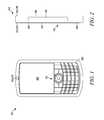
- FIGS. 1 and 2are front and side elevation views, respectively, of an exemplary mobile device that includes temperature sensing componentry that allows for differential temperature sensing, in accordance with one embodiment of the present invention
- FIG. 3is a block diagram illustrating exemplary components of the mobile device of FIG. 1 , including the temperature sensing componentry;
- FIG. 4is a schematic diagram illustrating various sensors and other components of the mobile device of FIGS. 1-3 , as well as illustrating how temperature signals from the temperature sensing componentry and other signals from other sensors are provided to and utilized by a processor of the mobile device in one embodiment of the present invention;
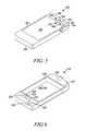
- FIGS. 5 and 6are front perspective views of two further exemplary embodiments of mobile devices having other arrangements of temperature sensing componentry, in accordance with other embodiments of the present invention.
- FIGS. 7 and 8respectively are additional perspective, partly cross-sectional, partly cutaway views of the mobile device of FIG. 6 . and a modified version of the mobile device of FIG. 6 , respectively;
- FIG. 9is a schematic illustration of an exemplary layout of multiple temperature sensing devices as can be arranged on a mobile device in another embodiment of the present invention.
- FIG. 10is a flow chart showing exemplary steps of operation of the mobile device of FIGS. 1-3 in determining an operational context of the mobile device based at least in part upon information from the temperature sensing componentry;
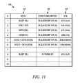
- FIG. 11is an exemplary look-up table that can be stored on a memory device of the mobile device of FIGS. 1-3 and consulted during performing of the process represented by the flow chart of FIG. 10 ;
- FIGS. 12 and 13are additional flow charts showing further exemplary steps of operation of the mobile device of FIGS. 1-3 in determining operational context of the mobile device based at least in part upon information from the temperature sensing componentry;
- FIG. 14is a schematic illustration of different types of mobile device operational contexts that can be determined by the mobile device acting in accordance with processes such as those shown in FIGS. 10 , 11 and 13 .
- FIGS. 1 and 2respectively, front and side elevation views are provided respectively of an exemplary mobile device 102 that includes temperature sensing componentry 104 that allows for detection of a temperature differential existing between different locations on the mobile device, in accordance with a first embodiment of the present invention.
- the mobile device 102is a personal digital assistant (PDA), albeit the mobile device is also intended to be representative of a variety of other mobile/portable devices that are encompassed within the scope of the present invention including, for example, cellular telephones, smart phones, other handheld or portable electronic devices, headsets, MP3 players, battery-powered devices, wearable devices, radios, navigation devices, pagers, and other mobile devices. Further included among the components of the mobile device 102 as shown in FIGS.
- PDApersonal digital assistant
- the video screen 106can in some circumstances also be a touch-screen.
- the temperature sensing componentry 104more particularly includes a first temperature sensing device 112 positioned along a front side 114 of the mobile device 102 and also a second temperature sensing device 116 positioned along a rear side 118 of the mobile device.
- temperature signalsarc provided from the first and second temperature sensing devices 112 , 116 that are indicative of the temperatures at those respective temperature sensing devices.
- the mobile deviceBy virtue of processing performed by the mobile device 102 utilizing the information communicated by way of the temperature signals, the mobile device is able to sense a temperature differential existing between the temperatures sensed by the two sensing devices (or two groups of sensing devices) which is indicative of a temperature differential existing between the locations at which those two sensing devices (or groups of sensing devices) are positioned on the front and rear sides 114 , 118 of the mobile device.
- This temperature differential informationis then used in combination with other information obtained via other types of sensors by the mobile device 102 to determine/predict an operational condition or context of the mobile device.
- the exemplary embodimentincludes wireless transceivers 202 , a processor 204 (e.g., a microprocessor, microcomputer, application-specific integrated circuit, etc.), a memory portion 206 , one or more output devices 208 , and one or more input devices 210 .
- a user interfaceis present that comprises one or more of the output devices 208 and one or more of the input device 210 .
- the internal components 200can further include a component interface 212 to provide a direct connection to auxiliary components or accessories for additional or enhanced functionality.
- the internal components 200preferably also include a power supply 214 , such as a battery, for providing power to the other internal components while enabling the mobile device 102 to be portable. As described in further detail below, the internal components 200 further include a plurality of sensors 228 . All of the internal components 200 can be coupled to one another, and in communication with one another, by way of one or more internal communication links 232 (e.g., an internal bus).
- a power supply 214such as a battery
- the internal components 200further include a plurality of sensors 228 . All of the internal components 200 can be coupled to one another, and in communication with one another, by way of one or more internal communication links 232 (e.g., an internal bus).
- Each of the wireless transceivers 202utilizes a wireless technology for communication, such as, but not limited to, cellular-based communication technologies such as analog communications (using AMPS), digital communications (using CDMA, TDMA, GSM, iDEN, GPRS, EDGE, etc.), and next generation communications (using UMTS, WCDMA, LTE, IEEE 802.16, etc.) or variants thereof, or peer-to-peer or ad hoc communication technologies such as HomeRF, Bluetooth and IEEE 802.11 (a, b, g or n), or other wireless communication technologies such as infrared technology.
- cellular-based communication technologiessuch as analog communications (using AMPS), digital communications (using CDMA, TDMA, GSM, iDEN, GPRS, EDGE, etc.), and next generation communications (using UMTS, WCDMA, LTE, IEEE 802.16, etc.) or variants thereof, or peer-to-peer or ad hoc communication technologies such as HomeRF, Bluetooth and IEEE 802.11
- the wireless transceivers 202include both cellular transceivers 203 and a wireless local area network (WLAN) transceiver 205 (which particularly can employ infrared technology), although in other embodiments only one of these types of wireless transceivers (and possibly neither of these types of wireless transceivers, and/or other types of wireless transceivers) is present. Also, the number of wireless transceivers can vary and, in some embodiments, only one wireless transceiver is present. Further, depending upon the embodiment, each wireless transceiver 202 can include both a receiver and a transmitter, or only one or the other of those devices.
- WLANwireless local area network
- Exemplary operation of the wireless transceivers 202 in conjunction with others of the internal components 200 of the mobile device 102can take a variety of forms and can include, for example, operation in which, upon reception of wireless signals, the internal components detect communication signals and the transceiver 202 demodulates the communication signals to recover incoming information, such as voice and/or data, transmitted by the wireless signals.
- the processor 204After receiving the incoming information from the transceiver 202 , the processor 204 formats the incoming information for the one or more output devices 208 .
- the processor 204formats outgoing information, which may or may not be activated by the input devices 210 , and conveys the outgoing information to one or more of the wireless transceivers 202 for modulation to communication signals.
- the wireless transceiver(s) 202convey the modulated signals to a remote device, such as a cell tower or a remote server (not shown).
- the input and output devices 208 , 210 of the internal components 200can include a variety of visual, audio and/or mechanical outputs.
- the output device(s) 208can include a visual output device 216 such as a liquid crystal display and light emitting diode indicator, an audio output device 218 such as a speaker, alarm and/or buzzer, and/or a mechanical output device 220 such as a vibrating mechanism.
- the visual output devices 216among other things can include the video screen 106 of FIG. 1 .
- the input devices 210can include a visual input device 222 such as an optical sensor (for example, a camera), an audio input device 224 such as a microphone, and a mechanical input device 226 such as a flip sensor, keyboard, keypad, selection button, touch pad, touchscreen, capacitive sensor, motion sensor, and switch.
- the mechanical input device 226can in particular include, among other things, the keypad 108 and the navigation device 110 of FIG. 1 .
- Actions that can actuate one or more input devices 210can include, but need not be limited to, opening the mobile device, unlocking the device, moving the device to actuate a motion, moving the device to actuate a location positioning system, and operating the device.
- the memory portion 206 of the internal components 200can encompass one or more memory devices of any of a variety of forms (e.g., read-only memory, random access memory, static random access memory, dynamic random access memory, etc.), and can be used by the processor 204 to store and retrieve data.
- the data that is stored by the memory portion 206can include, but need not be limited to, operating systems, applications, and informational data.
- Each operating systemincludes executable code that controls basic functions of the communication device, such as interaction among the various components included among the internal components 200 , communication with external devices via the wireless transceivers 202 and/or the component interface 212 , and storage and retrieval of applications and data to and from the memory portion 206 .
- Each applicationincludes executable code that utilizes an operating system to provide more specific functionality for the communication devices, such as file system service and handling of protected and unprotected data stored in the memory portion 206 .
- Informational datais non-executable code or information that can be referenced and/or manipulated by an operating system or application for performing functions of the communication device.
- the internal components 200 in the present embodimentfurther include the sensors 228 .
- the sensors 228 of the internal components 200can in at least some circumstances be considered as also being one or more input devices 210 or vice-versa (that is, although the sensors and input devices to some degree can overlap), given the particular significance of one or more of these sensors 228 to the present embodiment the sensors instead are described independently of the input devices 210 .
- the sensors 228include both temperature sensors 229 and other sensors 231 .
- the temperature sensors 229in particular include the first and second temperature sensing devices 112 , 116 .
- the temperature sensors 229can include any arbitrary number of sensors, and the temperature sensors can include a variety of different types of temperature sensing devices.
- the other sensors 231can include any one or more of a variety of different types of sensors.
- the other sensors 231include the side touch sensor (which can be a single touch sensor or multiple touch sensors) 119 , which can be a capacitive touch sensor, a resistive touch sensor, a temperature type sensor, a pressure sensor, an optical sensor, a mechanical sensor, or another type of touch-sensitive component.
- the other sensors 231can include, among other things, one or more proximity sensors such as infrared sensors and/or pyramid-type sensing assemblies as are described in U.S. patent application Ser. No. 12/471,062 entitled “Sensing Assembly for Mobile Device,” which is hereby incorporated by reference herein.
- the other sensors 231can include other types of sensors, such as a darkness/brightness sensor, a vibration sensor, an audio sensor, a location sensor or circuit, a Global Positioning System (GPS) receiver or sensor, a compass, a triangulation receiver, an accelerometer, a gravitometer, a tilt sensor, a gyroscope, a compass, or any other information collecting device that can identify a current location or orientation of the mobile device 102 .
- GPSGlobal Positioning System
- compasscompass
- triangulation receiveran accelerometer
- a gravitometera tilt sensor
- a gyroscopea compass
- the mobile device 102(and particularly the processor 204 ) is able to make determinations regarding operational condition(s)/context(s) and also regarding appropriate responses to those condition/context determinations, based upon signals provided from the temperature sensors 229 and other sensors 231 (including possibly one or more of the input devices 210 ).
- an electrical schematic diagram 250is provided showing how signals from temperature sensing devices such as the temperature sensing devices 112 , 116 of FIG. 1 can be processed to derive a differential temperature signal, as well as how that differential temperature signal can be processed along with other signals from other supporting sensors.
- the temperature sensing devices 112 , 116are coupled in series, between an inverting input 252 and a non-inverting input 254 of an operational amplifier 256 .
- a first lead 258 of the first temperature sensing device 112is coupled to the inverting input 252 by way of a first wire 260
- a second lead 262 of the first temperature sensing deviceis coupled to a first lead 264 of the second temperature sensing device 116 by way of a second wire 266
- a second lead 268 of the second temperature sensing deviceis coupled to the non-inverting input 254 by way of a third wire 270 .
- the operational amplifier 256In response to input signals (e.g., voltage or current signals) generated by the first and second temperature sensing devices (or groups of devices) 112 , 116 , the operational amplifier 256 in turn generates an output signal at terminal 272 that is proportional to the differential between the two input signals and thus proportional to the difference in temperatures experienced by the two temperature sensing devices.
- input signalse.g., voltage or current signals
- the operational amplifier 256In response to input signals (e.g., voltage or current signals) generated by the first and second temperature sensing devices (or groups of devices) 112 , 116 , the operational amplifier 256 in turn generates an output signal at terminal 272 that is proportional to the differential between the two input signals and thus proportional to the difference in temperatures experienced by the two temperature sensing devices.
- the differential temperature output signal provided at the output terminal 272is in turn sent to the processor 204 by way of a communication link 274 (although not shown, an analog-to-digital converter can be provided as part of the communication link 274 between the output terminal 272 and the processor 204 so that the differential temperature output signal is in digital form when provided to the processor 204 ).
- the processor 204also receives one or more signals from one or more of the other sensors 231 , for example, the side touch sensor 119 or one or more further sensors 276 , by way of additional communication links 278 and 280 , respectively.
- the communication links 274 , 278 and 280can all be considered to constitute as part of, or to be encompassed by, the communication links 232 of the mobile device 102 shown in FIG. 3 .
- the operational amplifier 256 and the wires 260 , 266 , 270are all considered to be part of the temperature sensors 229 (along with the temperature sensing devices 112 , 116 ), in other embodiments such devices/components other than the specific components that sense temperature can be considered to be distinct from the temperature sensors, and can be located physically apart from the temperature sensors.
- the operational amplifier 256can, in another embodiment, be considered part of the processor 204 .
- the processor 204can determine a variety of operational conditions/contexts as will be discussed in further detail below. Among other things, the processor 204 can in some embodiments or circumstances determine a location or position of the mobile device 102 in relation to a user or some other structure and/or make decisions based upon such determinations. For example, referring to FIG. 14 , in some embodiments that are discussed in more detail below, the mobile device 102 is able to determine whether it is within a pocket 284 of a user 286 or within a purse (or other similar bag-like container) 288 of the user.
- the processor 204upon performing such determinations, provides one or more output signals 282 to one or more components of the mobile device 102 so as to cause the mobile device to take one or more actions, or to perform one or more operations.
- the output signals 282can be provided to other component(s) of the mobile device 102 again by way of the communication links 232 of the mobile device 102 .
- the present inventionis intended to encompass numerous different embodiments in which temperature sensing devices are positioned at any of a variety of different locations on the mobile device, are implemented within the mobile device in numerous different ways, and have a variety of different types of structural configurations.
- FIGS. 5-9several examples of mobile devices with different arrangements and configurations of temperature sensing devices are shown. It is to be understood, however, that these additional embodiments (as well as the embodiment shown in FIG. 1 ) are merely examples of the present invention, and that the present invention is intended to encompass numerous other arrangements and configurations as well as those that are shown.
- an alternate embodiment of a mobile device 302has features that are similar to those of the mobile device 102 except insofar as the mobile device 302 includes a front logo region 304 as well as a rear logo region 306 (shown in phantom) respectively on a front side 313 and a rear side 319 of the mobile device. It is at (or, more particularly, around and beneath/inwardly of the front logo region 304 and the rear logo region 306 , respectively, that front and rear temperature sensitive devices 308 and 310 , respectively, are placed.
- each of the front temperature sensing device 308 and the rear temperature sensing device 310are looped structures that, as discussed in further detail below, in particular include thermocouple junctions that allow for temperature sensing to be accomplished.
- the respective temperature sensing devicessense the temperatures along the logo regions due to thermal conduction through those regions.
- the use of large areas such as the logo regions 304 , 306 coupled to the thermocouple junctions of the temperature sensing devices 308 , 310can help to assure user contact with the temperature sensing devices due to the logo large size.
- the first and second leads 312 and 314 of the first temperature sensing device 308can be considered analogous to the leads 258 and 262 , respectively, of FIG. 4
- the leads 312 and 314 of the second temperature sensing device 310can be considered analogous to the first and second leads 264 and 268 , respectively, of FIG. 4
- further componentssuch as the operational amplifier 256 of FIG. 4 are not shown in FIG. 5 , it can be presumed that the temperature sensing devices 308 , 310 can be operated and provide signals that are utilized in the same or substantially the same manner as was described with respect to FIG. 4 .
- the logo regions 304 , 306 of the mobile device 302are shown to be positioned proximate an upper edge surface 316 of the mobile device 302 , for example with the logo region 304 particularly being positioned in between the edge surface 316 and a screen 318 of the mobile device, it will be understood that the logo regions could be positioned at a variety of other locations along the front and rear sides 313 , 319 of the mobile device, as well as on other surfaces (e.g., the edge surface 316 or other edge/side surfaces) of the mobile device.
- a further mobile device 322is shown to include both a bezel 324 positioned along a front side 336 of the mobile device and a back plate 326 forming a rear surface 338 of the mobile device.
- the bezel 324is a rectangular-shaped structure having an open interior 340 , that is, a shape similar to that of a picture frame. It will be understood that, within the interior 340 , a display such as the screen 318 of FIG. 5 can be positioned.
- the mobile device 322includes first and second temperature sensing devices 328 and 330 that are positioned proximate the front and rear sides 336 and 338 , respectively.
- the first temperature sensing device 328is positioned adjacent to the bezel 324 along the interior side of the bezel (that is, not on the side of the bezel forming the exterior of the mobile device 322 ).
- the second temperature sensing device 330is positioned adjacent to the back plate 326 along the interior side of the back plate (again, not along the exterior surface forming the exterior surface of the mobile device 322 ).
- the bezel 324 and back plate 326are heat conductive plates that are either directly exposed to the outside environment or embedded very close to the outer surface of the mobile device.
- Each of the temperature sensing devices 328 , 330includes a junction allowing for temperature sensing as will be described in further detail below, and includes a respective first lead 332 as well as a respective second lead 334 .
- the leads 332 of the temperature sensing devices 328 , 330 respectivelycan be understood to correspond to the leads 258 and 268 of FIG. 4
- the leads 334 of the respective temperature sensing devicescan be understood to correspond to the leads 262 and 264 of FIG. 4 .
- the temperature sensing devices 328 , 330can be implemented in the same or substantially the same manner as discussed with reference to FIG. 4 .
- each of those respective temperature sensing devicessenses the temperature of a respective location exterior to the phone along the bezel 324 and back plate 326 by virtue of the conductive communication of heat through the bezel or the back plate, respectively.
- the mobile device 322includes a printed circuit board (PCB) 342 on which can be provided a variety of the electrical components of the mobile device, including, for example, the processor 204 and the memory 206 as well as the network communication links 232 (or portions thereof).
- the PCB 342is linked to the first and second leads 332 , 334 of the first temperature sensing device 328 as well as the second temperature device 330 (not shown) by way of spring contacts.
- a first spring contact 344links the PCB 342 with the first lead 332 of the first temperature sensing device 328
- a second spring contact 346links the PCB with the second lead 334 of the first temperature sensing device 328
- a third spring contact 348links the PCB with the first lead 332 of the second temperature sensing device (not shown)
- a fourth spring contact 350links the PCB with the second lead 334 of the second temperature sensing device.
- FIG. 8an additional perspective partly cross-sectional, partly cut-away view is provided of a modified version of the mobile device 322 shown to be a mobile device 352 .
- the mobile device 352is identical to the mobile device 322 , except insofar as while the mobile device 352 continues to employ the spring contacts 346 and 350 , in place of the spring contact 344 and 348 a different form of symmetrical contact formation 354 having a first contact portion 356 and a second contact portion 358 is utilized.
- the first and second contact portions 356 , 358are linked with one another by a middle portion that wraps around the edge of the PCB 342 .
- a given mobile devicecan have numerous interconnected temperature sensing devices above and beyond merely two temperature sensing devices. Indeed, depending upon the embodiment, a given mobile device can have any arbitrary number of temperature sensing devices positioned on any one or more of the surfaces (and within any one or more regions along those surfaces), and those various temperature sensing devices can be interconnected in any of a variety of manners. For example, in some embodiments, the mobile device need not have only one temperature sensing device on a given front, rear, or other surface of the mobile device. More particularly in this regard, referring to FIG.
- a front surface 360 of a mobile device 362is shown schematically to include eight different temperature sensing devices 364 on that front surface alone.
- the temperature sensing devices 364can be embedded within a screen such as a touch screen that extends over much of (or in the case of FIG. 9 ) even the entire front surface 360 of the mobile device 362 .
- the interconnected temperature sensing devicescan also, in one embodiment, be distributed on the housing skin (not within display glass) as small junctions or features exposed or minimally covered for aesthetics.
- the placement of the temperature sensing devices 364 so as to be embedded within the touch screen as shown in FIG. 9is in contrast to the embodiments of FIGS. 5-8 , where the temperature sensing devices 308 , 310 , 328 and 330 are positioned under (that is, on the interior surface of) heat conducting features of the mobile device such as the bezel 324 or the back plate 326 . Because of the placement of the temperature sensing devices 364 within the screen as shown in FIG. 9 , the mobile device 362 can have particularly advantageous temperature sensing performance.
- the temperature sensing devices 364are along the front surface 360 , it will be understood that similarly large numbers of temperature sensing devices can be positioned along other (e.g., rear or side) surfaces of the mobile device.
- the temperature sensing devices 364are distributed in a particular manner across the front surface 360 . More particularly, first, second, third and fourth ones of the temperature sensing devices 366 , 368 , 370 , and 372 , respectively, arc positioned in a line, one adjacent to the next, along a bottom edge 374 of the mobile device 362 , while fifth and sixth ones of the temperature sensing devices 376 and 378 , respectively, are positioned proximate left and right edges 380 and 382 , respectively, of the mobile device generally within a mid region 384 of the mobile device. Further, seventh and eighth ones of the temperature sensing devices 386 and 388 , respectively, are positioned proximate a top edge 390 of the front surface 360 , generally proximate the upper left and right corners of the mobile device.
- a graphite strip 373(shown in phantom) is placed across the front surface 360 that links up the first, second, third and fourth temperature sensing devices 366 , 368 , 370 and 372 for the purpose of heat conduction therebetween.
- the four temperature sensing devices 366 , 368 , 370 and 372are at the same or substantially the same temperature notwithstanding their somewhat different positions across the mobile device (and notwithstanding possible heat differences occurring internally within the mobile device, such as heat differences caused by the relative proximity of the different temperature sensing devices to heat-generating components such as a microprocessor within the mobile device).
- the four temperature sensing devices 366 , 368 , 370 and 372 proximate the bottom edge 374can be assumed to be at the same temperature that serves as a “common base line” with which to compare the temperatures sensed at the other temperature sensing devices 376 , 378 , 386 , 388 , This is helpful because the mobile device 362 can be assumed to have heat generating sources randomly located within it, such that the temperature profile within the mobile device 362 can also be non-uniform.
- the presence of the graphite strip 373ameliorates the temperature variations occurring due to the heat generated by such internal heat generating sources, at least for the purpose of the region encompassing the four temperature sensing devices 366 , 368 , 370 and 372 proximate the bottom edge 374 .
- the specific characteristics of the graphite strip 373can vary with the embodiment.
- FITC graphiteavailable from Tyk America, Inc. of Clairton, Pa. can be used, which has a thermal conductivity of approximately 700 W ⁇ K ⁇ 1 ⁇ m ⁇ 1 .
- HTC graphiteis advantageous in that it is relatively expensive, very thin (takes up little z-stack) and also available in an electrically non-conducting format.
- other types of graphitee.g., normal graphite
- strips of other types of thermally-conductive materialscan be used as (or in place of) the graphite strip 373 to equilibrate the temperature in the planar direction between the temperature sensing devices 366 , 368 , 370 , 372 , for example, strips made of copper, silver, aluminum, or even diamond.
- an electrically conductive materialsuch as copper is employed in place of the graphite strip 373
- such materialcan be rendered electrically non-conductive so as to prevent electrical conduction between the different temperature sensing devices 366 , 368 , 370 , 372 by coating the material with an electrically insulating surface/coating.
- thermally conductive linkscan be used in place of the graphite strip 373 depending upon the embodiment.
- the graphite strip 373 or other thermally-conductive strip linking the temperature sensing devices 366 , 368 , 370 and 372need not be present in all embodiments. Further, in some alternate embodiments, one or more other arrangements of graphite strips or other thermally conductive links can be present in addition to or instead of the graphite strip 373 so as to link up other combinations of the temperature sensing devices 364 so as to maintain those temperature sensing devices at the same or substantially the same temperature. For example, in another embodiment, a graphite strip could be used to thermally link up the fifth, sixth, seventh, and eighth temperature sensing devices 376 , 378 , 386 and 388 .
- thermocoupleswhich are voltage devices with Seebeck coefficients from about 5 to about 45 (e.g., on the order of 10) micro V/deg C.
- the materials out of which the thermocouples are formedcan vary depending upon the embodiment, and determine (at least in part) the voltages output by the thermocouples at different temperatures.
- the thermocouplesare formed by a junction of two different materials. For example, with respect to the embodiment of FIG.
- the temperature sensing devices 112 and 116can each be thermocouples formed by the junction of two metals, where the second lead 262 and second wire 266 are made of one metal while the first lead 258 , second lead 268 , first wire 260 and third wire 270 are made of a different metal.
- each of the temperature sensing devices 364is a thermocouple formed by a respective junction of first and second types of materials, which in the present embodiment are Indium Tin Oxide (InSnO 4 ) ceramic material (hereinafter referred to as ITO) and Indium Tin Oxide Manganese ceramic material (hereinafter referred to as ITO:Mn).
- thermocouple-type temperature sensing deviceit is the junction (that is, the point or surface interface where the two dissimilar metals meet before they part ways as two dissimilar wires/conductors) that is the temperature sensitive portion of the device, and the remainder of the device (e.g., the parting wires/conductors) merely allows for connection of the device to other hardware and does not influence temperature sensing performance.
- the placement of the thermocouple junctionis of particular interest so that temperature is sensed at the desired location. Further, in embodiments such as those of FIGS.
- thermocouple junction of a given temperature sensing devicephysically to its respective overlying structure (e.g., via welding, soldering, mechanical pressing, molding, etc).
- the logo regions 304 , 306 , bezel 324 , back plate 326 or other overlying structuresshould be configured so as to conduct/transfer heat quickly to the associated thermocouple junctions when touched (e.g., these structures should be thin and small to improve response time).
- FIGS. 1-9show two or more thermocouples that are connected in series
- any arbitrary number of thermocouples or other temperature sensing devicescan be connected serially or otherwise connected and utilized depending upon the embodiment.
- FIG. 9in particular illustrates an example where the eight temperature sensing devices 364 arranged along a single surface (namely, the front surface 360 ) of the mobile device 362 are all connected in one overall series connection.
- each of the temperature sensing devices 364is a thermocouple formed by a respective junction of an ITO lead and an ITO:Mn lead, and these leads are all interconnected in a manner by which all of the temperature sensing devices 364 are connected in series between a first terminal 391 and a second terminal 389 .
- first and second terminals 391 and 389respectively are coupled to respective copper wires 361 , 363 that are surrounded by a flexible plastic sheathe 365 so as to form a two-wire flex link.
- a flexible plastic sheathe 365extend away from the terminals 391 , 389 and allow those terminals to be coupled to other components (e.g., to an operational amplifier such as the operational amplifier 256 of FIG. 4 ).
- the first terminal 391is linked to the fifth temperature sensing device 376 by way of a first ITO lead 392 , and that temperature sensing device in turn is linked to the first temperature sensing device 366 by way of a first ITO:Mn lead 393 .
- the lead 393extends up to the second temperature sensing device 366 , and then a second ITO lead 394 extends from the first temperature sensing device to the seventh temperature sensing device 386 .
- a second ITO:Mn lead 395links the seventh temperature sensing device 386 to the second temperature sensing device 368 .
- a third ITO lead 396in turn links the second temperature sensing device 368 to the eighth temperature sensing device 388 , which then is connected to the third temperature sensing device 370 by way of a third ITO:Mn lead 397 , and the third temperature sensing device in turn is connected to the sixth temperature sensing device 378 by way of a fourth ITO lead 398 . Finally the sixth temperature sensing device 378 is connected to the fourth temperature sensing device 372 by way of a fourth ITO:Mn lead 399 .
- the fourth temperature sensing device 372is formed by the intersection of the lead 399 and the second terminal 389 , which is also an ITO lead.
- thermocouple-type temperature sensing devicesIn implementing thermocouple-type temperature sensing devices, the manner in which the device is interconnected with other components (and the correspondent polarity of the device relative to other components) often is of significance in implementing the device, particularly where multiple temperature sensing devices of this type are connected in series. For example, in an embodiment in which there are two thermocouple-type temperature sensing devices that are interconnected as shown in FIG. 4 , where it is intended that one of the thermocouple devices is on one side of the phone and the other thermocouple device is on the other side of the phone, it is typical that the respective polarities of the temperature sensing devices/thermocouples will be oppositely-orientated so as to allow for differential temperature sensing.
- the mobile device 362 of FIG. 9is an exemplary device in which multiple temperature sensing devices are distributed at three different general regions along a single surface (namely, the front surface 360 ) of the mobile device. Notwithstanding the fact that in this embodiment more than two temperature sensing devices are employed and coupled together in series, it is still possible to obtain meaningful temperature information because of the particular manner in which the temperature sensing devices are interconnected. As will be noticed from FIG.
- each of the temperature sensing devices 366 , 368 , 370 and 372 that are located proximate the bottom edge 374 of the mobile device 362are formed by the intersection of a respective one of the ITO:Mn leads extending away from the respective temperature sensing device generally upwardly and a respective ITO lead that extends away from each of those respective temperature sensing devices also generally upwardly but to the right of the respective ITO lead for that temperature sensing device (except in the case of the fourth temperature sensing device 372 , from which the ITO lead extends downwardly).
- each of the fifth and sixth temperature sensing devices 376 , 378 towards the midregion 384 of the mobile device 362is connected to a respective one of the ITO leads extending away from that temperature sensing device generally downwardly and also to one of the ITO:Mn leads extending generally downwardly and to the right of the respective ITO lead for that device (it is the same for the seventh and eighth temperature sensing devices 386 , 388 near the top edge 390 of the mobile device).
- the first, second, third, and fourth temperature sensing devices 366 , 368 , 370 , and 372all share a first polarity
- the fifth, sixth, seventh, and eighth temperature sensing devices 376 , 378 , 386 and 388all share a second polarity that is opposite the first polarity.
- Such reinforcing behavior of the sensors 366 , 368 , 370 , 372is particularly facilitated by the presence of the graphite strip 373 .
- the pairs of temperature sensing devices 376 , 378 , and 386 , 388 at those respective locationswill tend to generate voltages that are additive and reinforcing of one another, and the resulting output voltage experienced at the terminals 391 , 389 will be the sum of the contributions of any one or more of those temperature sensing devices.
- FIG. 9is reflective of certain assumptions regarding the operation of the mobile device 362 .
- the arrangement of the temperature sensing devices 364presumes that it is unlikely that a user will touch (that is, apply heat proximate to) both one or more of the temperature sensing devices 366 , 368 , 370 , 372 near the bottom edge 374 while at the same time touch one or more of the temperature sensing devices 376 , 378 , 386 , 388 at the midregion 384 or near the top edge 390 .
- FIG. 9additionally illustrates how, in some embodiments of the present invention, various advantages can be achieved by utilizing multiple temperature sensing devices provided within a given region on a given surface of the mobile device rather than utilizing only a single temperature sensing device to sense a temperature at a given region of the mobile device (as is presumed in the embodiment of FIG. 4 , for example).
- FIG. 9shows that multiple temperature sensing devices such as the devices 366 , 368 , 370 , 372 can be collectively employed, effectively as a single “group sensor”, so as to sense the temperature within a given region of the mobile device 362 , that is, proximate the bottom edge 374 of the mobile device.
- FIG. 9shows that multiple temperature sensing devices such as the devices 366 , 368 , 370 , 372 can be collectively employed, effectively as a single “group sensor”, so as to sense the temperature within a given region of the mobile device 362 , that is, proximate the bottom edge 374 of the mobile device.
- the multiple temperature sensing devices 376 , 378 , 386 , 386can be collectively employed, again effectively as a group sensor (or as multiple group sensors each made up of two temperature sensing devices), to sense the temperature(s) at either one or both of the midregion 384 and proximate the top edge 390 of the mobile device 362 .
- these temperature sensing devicesoperate as group sensors, temperature changes occurring nearing any of the sensing devices of the group sensor arc sensed quickly. This is in contrast to embodiments where only a single temperature sensing device is present within a given region, such that temperature changes must be communicated to the location of that particular temperature sensing device before those changes are sensed.
- FIG. 9illustrates how in some operational conditions it is possible for a variety of different temperature conditions within a variety of different regions of the mobile device can be sensed simply by series-connecting any arbitrary number of temperature sensing devices and using the simple hardware shown in (or hardware similar to that shown in) FIG. 4 .
- temperature changes experienced proximate the bottom edge 374 of the mobile device 362will have twice the effect as temperature changes experienced merely within the midregion 284 of the mobile device, since four of the temperature sensing devices 364 arc located near the bottom edge while only two of the temperature sensing devices 364 are located near the midregion 384 .
- the overall voltage signals produced by the series-connection of those temperature sensing devicescan be interpreted to determine temperature changes occurring at (and temperature differentials occurring between) those numerous different regions of the mobile device.
- sets of multiple temperature sensing devices positioned on different sides (e.g., the front and rear sides) of a mobile devicecan all be connected in series with one another.
- a set of temperature sensing devicesare intended to operate as a “group sensor” associated with a particular region of a mobile device, the proximity of those temperature sensing devices with respect to one another can vary depending upon the embodiment.
- one or more of the temperature sensing devicescan serve as a touch sensor (e.g., as the side touch sensor 119 ). For example, by placing the temperature sensing devices along sides (e.g., side edges) of the mobile device, it is then possible to determine which side of the mobile device is warmer and then conclude that the warmer side is the side the user is holding.
- sensed temperature informationcan be interpreted as an indication of keypad entries or other user input signals or instructions.
- a first set of temperature sensing devicese.g., 20 devices
- a second set of temperature sensing devices different in numbere.g., 1 device
- the mobile devicecan then detect whether the first region or the second region is touched based upon whether a voltage signal that is detected is large (e.g., from the 20 devices) due to heating of the first region from the user's finger, or small (e.g., from the 1 device) due to heating of the second region from the user's finger.
- a voltage signal that is detectedis large (e.g., from the 20 devices) due to heating of the first region from the user's finger, or small (e.g., from the 1 device) due to heating of the second region from the user's finger.
- thermosenorswithin a given region as a group sensor as discussed above
- embodimentssuch as those of FIGS. 5 and 6 in which a single temperature sensing device is connected to another overlying structure such as a logo region, bezel or back plate can be desirable.
- overlying structuresin particular allow for heat to be conducted to (or away from) the temperature sensing device from (or to) a variety of locations along the exterior surface of the mobile device as determined by the extent of the overlying structure.
- the use of an overlying structure in connection with a temperature sensing deviceallows for that temperature sensing-device to potentially be influenced by a user's touching of any portion of that overlying structure.
- thermocouple junctionsare situated immediately along the exterior of the mobile device (that is, the junctions just pierce out of the mobile device as “dots”).
- thermocouple junctionsare situated immediately along the exterior of the mobile device (that is, the junctions just pierce out of the mobile device as “dots”).
- Such embodimentscan provide even more rapid response times, in terms of how fast temperature changes are sensed, than embodiments where the thermocouple junctions are embedded within a touch screen (much less where the junctions are beneath overlying structures). In general, for quickest sensing/response times, it is desirable to minimize the distance between the thermocouple junction and the heat source.
- a flow chart 400shows exemplary steps of a process of operation of a mobile device such as the mobile device 102 , in which the mobile device utilizes differential temperature information obtained by way of temperature sensing componentry such as the first and second temperature sensing devices 112 , 116 in order to make determination(s) regarding an operational context of the mobile device and/or decision(s) regarding further operation(s) of the mobile device in view of the determined operational context.
- temperature sensing componentrysuch as the first and second temperature sensing devices 112 , 116
- the mobile device 102can depending upon the circumstances be operating in a voice mode (that is, a mode in which the mobile device is transmitting and/or receiving voice information), a data mode (where data is being transmitted and/or received), a video mode (where video information is being transmitted and/or received), and/or a combination of two or more of these modes.
- a voice modethat is, a mode in which the mobile device is transmitting and/or receiving voice information
- a data modewhere data is being transmitted and/or received
- a video modewhere video information is being transmitted and/or received
- a “context”refers to the physical position of the mobile device in relation to one or more other structures (or being physically apart from one or more other structures), such as being within the pocket 284 (e.g., a shirt pocket as shown, or a pants pocket, or a jacket pocket) or purse 288 as shown in FIG. 14 , being on a table or desk top or other substantially rigid, substantially horizontal surface, or being suspended in the air.
- the mobile device 102determines its expected or predicted thermal profile value ( ⁇ Tfb) in view of the particular operational mode of the mobile device 102 as determined in the step 404 , as well as in view of a presumed operational context.
- the expected thermal profile valueis the temperature differential that would be expected to be measured by way of the temperature sensing devices 112 , 116 given a particular operational mode and a particular operational context of the mobile device 102 (the abbreviation ⁇ Tfb in particular refers to the temperature differential between the front side temperature sensing device 112 and the back side temperature sensing device 116 ).
- the mobile device 102determines its expected thermal profile value by consulting information available from a look-up table 420 stored in the memory portion 206 of the mobile device 102 . That is, by using the information obtained by the mobile device 102 in the step 404 regarding its current operational mode, and assuming a particular operational context, the mobile device is able to consult the look-up table 420 during the step 406 to obtain its expected thermal profile value in view of that current operational mode information and operational context information.
- the look-up table 420can contain a variety of expected thermal profile values corresponding to a variety of operational modes and/or contexts of a mobile device.
- the look-up table 420includes both a first column 414 in which are listed a variety of possibilities of operational modes (e.g., voice, data, sleep) of the mobile device 102 , as well as a second column 416 in which are listed a variety of possibilities of contexts/conditions of the mobile device (again for example, the mobile device can be suspended within quiescent air of a particular temperature, or possibly in some other environment such as a pocket or purse).
- a third column 418identifies the expected thermal profile value corresponding to each particular pair of possibilities from the first and second columns 414 , 416 .
- the expected thermal profile values stored in the look-up table 420typically are obtained by way of testing done upon the mobile device 102 by the manufacturer (e.g., in the factory) prior to the sale of the mobile device to a consumer, and this stored information is then provided as part of the mobile device when it is sold to the consumer.
- the same look-up tablecan be used for all mobile devices of the same model/type (which are assumed to be identical).
- the manufacturer measurementsare preferably be done on a statistical sample of mobile devices of a particular model/type and then considered standard across all others.
- “In quiescent air”can be understood to be a test condition where the mobile device is suspended mid-air in a room having air that is at rest and at a particular assumed temperature.
- the expected thermal profile valueis particularly determined from the look-up table 420 based upon the present operational mode status of the mobile device 102 . Nevertheless, in other embodiments, the expected thermal profile value can be based upon information regarding the past operational mode status of the mobile device 102 in addition to, or instead of, the current operational mode status. Further, in some embodiments, the expected thermal profile value can be a value that is periodically-determined or tracked by the mobile device 102 during its operation over time. Also, in some embodiments, the expected thermal profile value given certain operational circumstances of the mobile device can further be adjusted to take into account past operational circumstances, such as the amount of recent operational activity of the mobile device 102 , etc.
- the processthen advances to a step 408 .
- the mobile device 102takes into account signal(s) from one or more of the other sensors 231 that are indicative of particular mobile device operational context information that is of interest and, based upon such signal(s), makes a preliminary or “first prediction” regarding the true operational context of the mobile device that is of particular interest, e.g., whether the mobile device is within the operator's pocket 284 , within the purse 288 , etc.
- signals from one or more of a camera, infrared sensor, audio sensor, compass, global positioning system sensor, touch sensor, tilt sensor, etc.can be considered in making this prediction.
- signals from the side touch sensor 119can be of particular value. To the extent that signals provided from the side touch sensor 119 indicate that the sensor is being touched, those signals can be interpreted as an indication that the mobile device 102 is within an operator's hand and consequently not within the operator's pocket or purse.
- the mobile device 102particularly takes into account information from its own sensors
- the mobile devicecan take into account information from other (e.g., remote) sources as well.
- the mobile devicecan determine its own position using location information determined by way of GPS (or other devices or methods) and then based upon this information interrogate a data source external to the mobile device (e.g., by way of a network connection, such as one available via the wireless transceivers 202 ) to obtain temperature, humidity, other weather-related information (e.g., whether the weather will be sunny or cloudy) or other remote sensor information about the general region in which the mobile device is presently located.
- a data sourcee.g., by way of a network connection, such as one available via the wireless transceivers 202
- weather-related informatione.g., whether the weather will be sunny or cloudy
- the external data sourcecan be any of a variety of data sources including, for example, web-accessible databases (e.g., www.weatherchannel.com), other external databases, or external sensors. Data obtained in such a manner can then be used by the mobile device to modify the prediction values stored in the look-up table 420 (particularly in the column 418 ). For example, if the humidity exceeds a threshold, the data in the column 418 can be modified to account for the high humidity.
- the mobile device 102Upon completion of the step 408 , at a step 410 the mobile device 102 then determines a current, actual thermal profile value ( ⁇ Tfbm) as measured by the first and second temperature sensing devices 112 , 116 (or other temperature sensing componentry depending upon the embodiment). That is, the mobile device 102 takes the temperature measurements provided by the first and second temperature sensing devices 112 , 116 and determines the temperature differential there between to be the actual thermal profile value.
- ⁇ Tfbma current, actual thermal profile value
- the mobile device 102compares the actual thermal profile value ( ⁇ Tfbm) with the expected thermal profile value (AM) obtained from the look-up table 420 in step 406 given the particular operating mode of the mobile device 102 and, based upon that comparison as well as the first prediction from the context information obtained at the step 408 , determines an operational context of the mobile device. Once the operational context is determined, then the mobile device 102 can further take one or more particular actions suitable in view of that operational context as described in further detail.
- FIGS. 12 and 13exemplary flow chart substeps corresponding to the aforementioned step 412 relating to the determining of the operational context of the mobile device 102 are shown.
- FIG. 12particularly shows exemplary flow chart substeps 430 in which the mobile device 102 determines that the operational context of the mobile device is or is not within a pocket (such as the pocket 284 of FIG. 14 ) and, if within a pocket, a directional orientation of the mobile device within the pocket.
- FIG. 12shows particular actions that the mobile device 102 can take upon determining that the mobile device is within a pocket.
- FIG. 13particularly shows exemplary flow chart substeps 460 in which the mobile device 102 determines that the operational context of the mobile device is or is not within a purse, as well as actions that can be taken by the mobile device upon determining that it is within a purse.
- the mobile device 102compares the measured thermal profile value ⁇ Tfbm with a particular one of the expected thermal profile values ⁇ Tfb.
- the expected thermal profile valueis ⁇ Tfb/a, that is, a value from the look-up table 420 that corresponds to a presumed operational context of the mobile device 102 within quiescent air of a particular assumed temperature.
- the processadvances to different steps.
- the mobile device 102proceeds to a step 434 at which the mobile device further determines whether the side touch sensor 119 has been touched. If the side touch sensor 119 has been touched, then the mobile device 102 proceeds to a step 452 , at which it is concluded that the mobile device is not within a pocket.
- the mobile device 102proceeds to a step 436 , at which the mobile device 102 determines whether it is tilted so as to be at an orientation other than horizontal (it being understood that horizontal orientation most likely indicates a table surface) plus or minus some minor (delta) angle (e.g., +/ ⁇ 0.5 degrees off of horizontal). This determination can be made using signal(s) received from one or more of the other sensor(s) 231 such as an accelerometer, gravitometer, or tilt sensor of the mobile device 102 that are indicative of the physical orientation of the mobile device.
- the other sensor(s) 231such as an accelerometer, gravitometer, or tilt sensor of the mobile device 102 that are indicative of the physical orientation of the mobile device.
- the processadvances to the step 452 at which the mobile device is predicted to not be in a pocket. This prediction is made because, in the event the mobile device is approximately horizontal, it is highly unlikely (although not impossible) that the mobile device is in a pocket. Rather, in such circumstance, it is likely that the mobile device 102 is on a table or desk top.
- the processadvances to a step 438 , at which changes experienced by the mobile device 102 in terms of vibration and positioning are considered.
- the processadvances to a step 440 at which it is predicted that the mobile device is within an operator's pocket. Otherwise, lacking detectable vibrations, accelerations, tilting, movement or other positioning changes (small or otherwise) over a given predetermined time period, then the process concludes with the step 452 at which the phone is predicted to not be in an operator's pocket.
- minor vibration or acceleratione.g., due to vibration/breathing while the user is stationary
- significant tilting or other movementsincluding movements that are essentially large-scale vibrations (e.g., changing tilt/orientation that occurs while the user is walking) over a period of time (typically, settable/resettable)
- the processadvances to a step 440 at which it is predicted that the mobile device is within an operator's pocket. Otherwise, lacking detectable vibrations, accelerations, tilting, movement or other positioning changes (small or otherwise) over a given predetermined time period, then the process concludes with the step 452 at which the phone is predicted to not be in an operator's pocket.
- the measured thermal profile valueis greater than the expected thermal profile value.
- this informationcan be interpreted as an indication that temperature at the first temperature sensing device 112 along the front side 114 of the mobile device 102 is higher than the temperature at the second temperature sensing device 116 along the rear side 118 of the mobile device.
- the higher temperature front side of the mobile deviceis the side of the mobile device that is closer to the operator's body.
- the mobile device at the step 432While a determination that the measured thermal profile value is greater than the expected thermal profile value at the step 432 results in the subsequent performance of step 434 and can ultimately result in a prediction at the step 440 that the front side 114 of the mobile device 102 is facing the operator's body, as shown the mobile device at the step 432 also can determine that the measured thermal profile is less than or equal to the expected thermal profile value. Assuming that the two thermal profiles are determined to be equal, then the process advances immediately from the step 432 to the step 452 , at which the mobile device is predicted to not be in an operator pocket. This is appropriate since, in almost all circumstances in which the mobile device 102 is in an operator pocket, there will be experienced across the mobile device a temperature differential corresponding to the relative distances of the sensing devices relative to the operator's body.
- the mobile device 102performs one or more of additional steps 444 , 446 , 448 and 450 that are identical to the steps 434 , 436 , 438 and 440 , respectively, except insofar as at the step 450 it is predicted that the mobile device is in an operator pocket and positioned such that the rear side 118 is facing the operator's body. That is, if at a step 444 it is determined by the mobile device 102 that the side touch sensor 119 has been touched, then the mobile device proceeds to the step 452 while, if not, the mobile device advances to the step 446 .
- the mobile device 102determines that it is within a pocket with its rear side closer to the body of the operator.
- the processadvances to a step 442 at which the mobile device then takes one or more actions in response thereto.
- the particular action or actions that are takencan vary depending upon the embodiment or the circumstance and, in some embodiments, no action(s) need be taken (or no action(s) need be taken right away).
- the one or more action(s) that can be taken by the mobile device 102can include, for example, locking of the screen and/or certain of the input devices 210 of the mobile device (e.g., to prevent mis-dialing).
- the mobile device 102can reconfigure its operation so that radio frequency (RF) signals are better received and/or transmitted from the mobile device (among other things, in this regard, the antenna operation of the mobile device can be adjusted so that signals are directed away from the body of the operator).
- RFradio frequency
- one or more types of alert types or levelscan be modified to reflect the presence of the mobile device 102 in an operator pocket.
- the mobile device 102can be automatically set to a vibrate alert type since such vibration might easily be felt by an operator while the mobile device was in the operator's pocket.
- the mobile device 102upon determining its presence in an operator pocket, the mobile device 102 also can enable or disable one or more particular wireless (e.g., Bluetooth or WiFi) interfaces, set or reset the operation mode of the mobile device (e.g., from data mode to voice mode), set or reset one or more operator preferences, and/or adjust the manner in which the mobile device filters and/or processes incoming calls.
- the mobile device 102can take one or more action(s) to conserve power, particularly, action(s) that shut down or place into a hibernation state certain function(s) that typically are not required or desired when the mobile device is within a pocket. Such functions can include, further for example, shutting down display lighting functions, camera applications, etc.
- any one or more of the above-identified actionscan be taken by the mobile device 102 upon the process reaching the step 442 .
- the above descriptionis not intended to be exhaustive of all possible action(s) that can potentially be taken, but rather is merely intended to be representative of some of the variety of action(s) that potentially can be taken in view of the mobile device's determination that it is within an operator pocket.
- the flow chart substeps 460can be performed instead of the flow chart substeps 430 of FIG. 12 or, alternatively, subsequent to the flow chart substeps 430 particularly after the step 452 is reached.
- the flow chart substeps 460begin with a step (substep) 462 at which the mobile device 102 compares the measured thermal profile value ⁇ Tfbm with a particular one of the expected thermal profile values ⁇ Tfb (sl/p) corresponding to operation within a purse. If the two values are not equal, in this example, the mobile device 102 immediately proceeds to a step 464 at which the mobile device concludes that it is not within a purse.
- the processadvances to a step 466 , at which it is determined whether at least one side touch sensor such as the side touch sensor 119 is being touched. If signal(s) from such touch sensor(s) indicate touching, then at a step 468 the mobile device 102 further determines whether the sensed touching is non-changing touching that could correspond to touching signals arising from the resting of the mobile device 102 in a particular manner within a purse. Such touching could also potentially occur due to pressure placed upon keys on the mobile device 102 . If the sensed touching is not non-changing, then the process again proceeds to the step 464 and it is determined that the mobile device 102 is not within a purse.
- the processadvances to a step 470 .
- the mobile device 102determines whether the mobile device is tilted horizontal plus or minus a small (delta degrees) angle such that it is likely the mobile device is located on a table top or desk top. As discussed above, such a determination can be arrived at using signals from one or more of the other sensors 231 such as an accelerometer, gravitometer or tilt sensor. If the orientation of the mobile device 102 is approximately-horizontal, again the mobile device concludes at the step 464 that it is not within a purse.
- the processadvances from the step 470 to a step 472 , at which the mobile device 102 next determines whether it is in a dark environment, as can be determined by way of another of the other sensors 231 such as a light sensor.
- the level of darkness indicative of a dark environmentcan be set to varying levels depending upon the embodiment or circumstances. If the environment detected by the mobile device is determined not to be dark, then the mobile device 102 again proceeds to the step 464 and concludes that it is not in a purse. However, if the environment is determined to be dark, then the process advances to a step 474 .
- the mobile device 102receives image information provided by a camera (another of the other sensors 231 ) of the mobile device 102 regarding an image perceived by the camera (e.g., a snapshot of the surrounding environment).
- the processor 204processes the image information and makes a determination of whether the image information is or is not indicative of the mobile device 102 being within a purse. If the image information, as processed, indicates that the mobile device 102 is not in a purse (for example, because the image information appears to represent a human face or another recognizable item), then the process concludes at the step 464 that the mobile device 102 is not in a purse. Alternatively, if the image information as processed indicates that the mobile device 102 is within a purse (or is not inconsistent with the mobile device being within a purse), then the process advances to a step 476 .
- the mobile device 102is provided with information from an electrical (or ground) isolation detector (another of the other sensors 231 ) of the mobile device and, at that step, further determines based upon the information from that sensor whether the mobile device appears to be isolated from earth ground (and/or isolated from an operator). While sensed isolation would tend to indicate that the mobile device is within (e.g., “floating within”) a non-conductive purse, an absence of isolation would tend to indicate that mobile device is being held by an operator in the operator's hand or otherwise not in a purse.
- the processagain concludes at the step 464 that the mobile device 102 is not within a purse, but if isolation is sensed, then the process advances further to a step 478 , at which the mobile device 102 predicts that it is indeed within a purse.
- the mobile device 102can take one or more of a variety of actions that are appropriate given the mobile device's context. More particularly, subsequent to the step 478 , at a step 480 , the mobile device 102 can switch its manner of operation to a “Power Save” manner of operation by shutting down and/or disabling non-viewable functions and/or other functions that are non-useful assuming that the mobile device is within a purse.
- Such functionscan include, for example, backlighting, camera, video display, and other functions.
- the mobile device 102can adjust its type of alert and/or the loudness of the alert to reflect the positioning of the mobile device within a purse. Such adjustments can be made to reflect user preferences, based upon one or more filtering mechanisms, and/or to prioritize incoming user calls, and the manner of such adjustments can be determined based upon, among other things, inputs previously-entered by an operator. Additionally at the step 480 , the mobile device can also enable (or disable) wireless Bluetooth and/or WiFi communication.
- detection of operational context by the mobile device 102allows the mobile device to adjust its operational performance in view of the detected context so as to achieve enhanced or modified performance in a variety of manners, including enhanced or modified performance in terms of the user interfacing that is provided, the power usage of the mobile device, the operational mode(s) (including mode(s) of wireless communications) of the mobile device, and/or in other manners.
- the mobile device 102takes into account sensed differential temperature information as being of primary interest, where the sensed differential temperature information can include information from a single pair of temperature sensors (representing the temperature differential therebetween) or possibly multiple pairs of temperature sensors (it also being understood that any given sensor can be part of more than one “pair” of temperature sensors). Notwithstanding the significance of sensed differential temperature information, in many embodiments of the present invention, the mobile device 102 takes into account both differential temperature information as well as one or more other types of sensor information and device mode and settings.
- the use of multiple types of different sensory information including differential temperature information in determining whether the mobile device 102 is in a pocket or purse or other operational contextallows for more effective and accurate (or unique) determinations in this regard, notwithstanding variations in the circumstances such as variations in the type of clothing of an operator's pocket (e.g., material, thickness, texture, color, pocket size, etc.) or the presence of other objects (e.g., metal objects, etc.) within a purse.
- the use of multiple types of different sensory information including differential temperature informationin particular enables the mobile device 102 to detect its operational context in circumstances or environments where it might otherwise be difficult to ascertain operational context with a more limited sensing capability.
- Embodiments of the present inventionthat employ one or more pairs of sensors that allow for sensing temperature differences between different locations on the phone (at which the different sensors of a given pair are located) can be particularly low in cost, simple, and reliable.
- accuracy in terms of measuring actual temperaturesis not required, since instead it is differences in temperature (and particularly changes in temperature delta, which are typically small or even miniscule in magnitude) between different locations on the device that are monitored.
- stored informationsuch as that of the look-up table, sensor information or other information, internally-generated hardware heat can be accounted for.
- such internally-generated heatcan also be distinguished from other thermal influences such as the heat from a user's fingers/hand as they touch the mobile device 102 .
- the differential temperature sensing capabilitycan be implemented in a simple, cost-effective manner as discussed above, using simple hardware (again, thermo wires/thermocouples, opAmp and an analog-to-digital converter, for instance).
- the implementation of the differential temperature sensorscan be done in such a manner as to be consistent with the overall layout of the mobile device (e.g., take a “phone-friendly” implementation), for example, by making use of standard housing features of the mobile device as the temperature sensing plates (e.g., the display bezel, phone logo, etc).
- the particular sensory information that is considered by the mobile device 102 in predicting its operational contextcan vary considerably and need not follow the steps discussed above. For example, notwithstanding the particular steps 434 - 438 and 444 - 448 discussed above in which various sensory information is considered by the mobile device 102 in determining whether the mobile device is within a pocket, and notwithstanding the particular steps 466 - 476 discussed above in which various sensory information is considered by the mobile device in determining whether it is within a purse, the particular sensory information (and steps involved in considering such sensory information) can vary depending upon the embodiment of the invention. For example, with respect to FIG.
- step 474is not performed and camera image information is not considered by the mobile device 102 , and the process advances immediately to the step 476 upon determining that the mobile device is in a dark environment at the step 472 .
- the step 476is not performed and isolation is not considered in determining whether the mobile device 102 is within a. purse, and thus the process advances immediately to the step 478 upon determining that the camera image does not indicate that the mobile device is not in a purse at the step 474 .
- neither the step 474 nor the step 476are performed.
- the present inventionis intended to encompass a variety of types of temperature sensing devices and configurations thereof in addition to those specifically described above.
- serially-connected temperature sensing devices intended to provide voltage outputswere particularly discussed above, it will be understood that in some other embodiments temperature sensing devices providing current outputs can also or instead be used and further that in some other embodiments multiple temperature sensing devices can be coupled in parallel with one another rather than coupled in series.
- multiple temperature sensing devicescan be coupled in parallel with one another rather than coupled in series.
- the present inventionis also intended to relate to other embodiments, in which differential temperature sensing is implemented on other electronic devices rather than merely mobile devices.
Landscapes
- Engineering & Computer Science (AREA)
- Environmental & Geological Engineering (AREA)
- Human Computer Interaction (AREA)
- Computer Networks & Wireless Communication (AREA)
- Signal Processing (AREA)
- Telephone Function (AREA)
- Testing Or Calibration Of Command Recording Devices (AREA)
Abstract
Description
Claims (17)
Priority Applications (4)
| Application Number | Priority Date | Filing Date | Title |
|---|---|---|---|
| US12/774,509US8963845B2 (en) | 2010-05-05 | 2010-05-05 | Mobile device with temperature sensing capability and method of operating same |
| CN201180022502.9ACN102884841B (en) | 2010-05-05 | 2011-04-05 | There is mobile device and the method for operation thereof of Temperature sensing capabilities |
| PCT/US2011/031161WO2011139456A2 (en) | 2010-05-05 | 2011-04-05 | Mobile device with temperature sensing capability and method of operating same |
| EP11717060.5AEP2567575B1 (en) | 2010-05-05 | 2011-04-05 | Mobile device with temperature sensing capability and method of operating same |
Applications Claiming Priority (1)
| Application Number | Priority Date | Filing Date | Title |
|---|---|---|---|
| US12/774,509US8963845B2 (en) | 2010-05-05 | 2010-05-05 | Mobile device with temperature sensing capability and method of operating same |
Publications (2)
| Publication Number | Publication Date |
|---|---|
| US20110273378A1 US20110273378A1 (en) | 2011-11-10 |
| US8963845B2true US8963845B2 (en) | 2015-02-24 |
Family
ID=44120942
Family Applications (1)
| Application Number | Title | Priority Date | Filing Date |
|---|---|---|---|
| US12/774,509Active2031-05-31US8963845B2 (en) | 2010-05-05 | 2010-05-05 | Mobile device with temperature sensing capability and method of operating same |
Country Status (4)
| Country | Link |
|---|---|
| US (1) | US8963845B2 (en) |
| EP (1) | EP2567575B1 (en) |
| CN (1) | CN102884841B (en) |
| WO (1) | WO2011139456A2 (en) |
Cited By (10)
| Publication number | Priority date | Publication date | Assignee | Title |
|---|---|---|---|---|
| US20140118246A1 (en)* | 2012-11-01 | 2014-05-01 | Pantech Co., Ltd. | Gesture recognition using an electronic device including a photo sensor |
| US20140358318A1 (en)* | 2013-06-04 | 2014-12-04 | Mediatek Inc. | Thermal control method and thermal control module applicable in a portable electronic device |
| US20160366639A1 (en)* | 2015-06-12 | 2016-12-15 | Motorola Mobility Llc | Method and Apparatus for In-Pocket Detection by an Electronic Device |
| US10043428B2 (en) | 2016-05-25 | 2018-08-07 | Microsoft Technology Licensing, Llc | Evaluation of a display temperature |
| US10118696B1 (en) | 2016-03-31 | 2018-11-06 | Steven M. Hoffberg | Steerable rotating projectile |
| US20180332253A1 (en)* | 2017-05-10 | 2018-11-15 | Olympus Corporation | Information recording apparatus, information recording system and method for controlling information recording apparatus |
| WO2019212156A1 (en)* | 2018-05-04 | 2019-11-07 | 삼성전자 주식회사 | Electronic device for heating control, and operating method therefor |
| US10591965B2 (en) | 2017-01-20 | 2020-03-17 | Qualcomm Incorporated | System and method for context-aware thermal management and workload scheduling in a portable computing device |
| KR20220143597A (en)* | 2021-04-16 | 2022-10-25 | 애플 인크. | Temperature sensing systems and methods for an electronic device |
| US11712637B1 (en) | 2018-03-23 | 2023-08-01 | Steven M. Hoffberg | Steerable disk or ball |
Families Citing this family (67)
| Publication number | Priority date | Publication date | Assignee | Title |
|---|---|---|---|---|
| US9110534B2 (en) | 2010-05-04 | 2015-08-18 | Google Technology Holdings LLC | Stylus devices having variable electrical characteristics for capacitive touchscreens |
| PL2405662T3 (en)* | 2010-07-08 | 2013-04-30 | Advanced Digital Broadcast Sa | An interactive glasses system |
| US8311522B1 (en)* | 2010-09-28 | 2012-11-13 | E.Digital Corporation | System and method for managing mobile communications |
| US8509842B2 (en)* | 2011-02-18 | 2013-08-13 | Microsoft Corporation | Automatic answering of a mobile phone |
| TW201239735A (en)* | 2011-03-29 | 2012-10-01 | Hon Hai Prec Ind Co Ltd | System and method for protecting a display screen of an electronic device |
| US8890823B2 (en)* | 2012-01-09 | 2014-11-18 | Motorola Mobility Llc | System and method for reducing occurrences of unintended operations in an electronic device |
| US20130063368A1 (en)* | 2011-09-14 | 2013-03-14 | Microsoft Corporation | Touch-screen surface temperature control |
| KR101840852B1 (en)* | 2011-10-10 | 2018-03-22 | 삼성전자주식회사 | Surface temperature management method of mobile device and memory thermal management method of multichip package |
| US8963885B2 (en) | 2011-11-30 | 2015-02-24 | Google Technology Holdings LLC | Mobile device for interacting with an active stylus |
| US9063591B2 (en) | 2011-11-30 | 2015-06-23 | Google Technology Holdings LLC | Active styluses for interacting with a mobile device |
| US8886214B2 (en)* | 2011-12-19 | 2014-11-11 | Adobe Systems Incorporated | Method and apparatus for increasing accuracy of wireless based real-time location system (RTLS) devices |
| CN103294233A (en)* | 2012-02-27 | 2013-09-11 | 富泰华工业(深圳)有限公司 | Touch screen and touch display device provided with same |
| JP2013232804A (en)* | 2012-04-27 | 2013-11-14 | Fujitsu Ltd | Terminal device, backlight control method, and backlight control program |
| EP2682715B1 (en) | 2012-07-02 | 2015-03-11 | Sensirion AG | Portable electronic device |
| US10085140B2 (en) | 2012-07-13 | 2018-09-25 | International Business Machines Corporation | Preventing mobile communication device data loss |
| CN103179261B (en)* | 2012-07-18 | 2015-09-09 | 深圳市金立通信设备有限公司 | The system and method for controlling mobile phone through speech is realized based on ambient temperature |
| US11405841B2 (en)* | 2012-07-20 | 2022-08-02 | Qualcomm Incorporated | Using UE environmental status information to improve mobility handling and offload decisions |
| US8665238B1 (en)* | 2012-09-21 | 2014-03-04 | Google Inc. | Determining a dominant hand of a user of a computing device |
| CN103853989A (en)* | 2012-11-29 | 2014-06-11 | 鸿富锦精密工业(武汉)有限公司 | Temperature key and computer security protection method |
| US9883389B2 (en) | 2012-12-14 | 2018-01-30 | Facebook, Inc. | Techniques for communicating notifications to subscribers |
| US9024738B2 (en) | 2013-02-01 | 2015-05-05 | Blackberry Limited | Apparatus, systems and methods for mitigating vibration of an electronic device |
| US9152271B2 (en) | 2013-02-06 | 2015-10-06 | Honeywell International Inc. | Automatic and dynamic sensitivity control of projected capacitive touch sensitive detection systems |
| US9426747B2 (en)* | 2013-03-12 | 2016-08-23 | Qualcomm Incorporated | Hands-off detection and deactivation for handheld user devices |
| US9244888B2 (en)* | 2013-03-15 | 2016-01-26 | Microsoft Technology Licensing, Llc | Inferring placement of mobile electronic devices |
| CN103196574B (en)* | 2013-03-20 | 2015-10-14 | 小米科技有限责任公司 | The method of measures ambient temperature and device |
| CN104063043B (en)* | 2013-03-22 | 2017-07-25 | 联想(北京)有限公司 | A kind of control method and device |
| CN104123081B (en)* | 2013-04-23 | 2017-04-26 | 神讯电脑(昆山)有限公司 | Electronic device and sleep awakening method thereof |
| CN104158948A (en)* | 2013-05-14 | 2014-11-19 | 腾讯科技(深圳)有限公司 | Method and device for adjusting ringtone of mobile terminal |
| US10446888B2 (en)* | 2013-05-31 | 2019-10-15 | Legends | Battery heating element |
| EP2808652B1 (en) | 2013-05-31 | 2016-11-16 | Sensirion AG | Portable electronic device with integrated temperature sensor being compensated by other sensing data |
| WO2015030869A1 (en)* | 2013-08-28 | 2015-03-05 | Bodhi Technology Ventures Llc | Sensor for detecting presence of material |
| EP2846135B1 (en)* | 2013-09-10 | 2020-04-29 | Sensirion AG | Portable Electronic Device with Environmental Sensor |
| US9618945B2 (en) | 2013-09-22 | 2017-04-11 | Microsoft Technology Licensing, Llc | Monitoring surface temperature of devices |
| TWI504869B (en)* | 2014-03-19 | 2015-10-21 | Radiant Innovation Inc | Externally-connected infrared temperature sensing module and method of sensing temperature thereof, and externally-connected infrared temperature sensing system |
| EP2963402B1 (en)* | 2014-07-01 | 2019-05-08 | Nxp B.V. | Method of operating a mobile device, computer program product and mobile device |
| CN104156168B (en)* | 2014-08-08 | 2018-04-06 | 惠州Tcl移动通信有限公司 | The unlocking method and its system of a kind of mobile terminal |
| CN105338167B (en) | 2014-08-08 | 2020-05-08 | 中兴通讯股份有限公司 | Automatic execution method and device for mobile terminal operation and mobile terminal |
| EP2993451B1 (en)* | 2014-09-05 | 2017-10-11 | Nxp B.V. | Method of predicting an ambient temperature around a mobile device, computer program product and mobile device |
| US9681765B2 (en)* | 2014-09-30 | 2017-06-20 | Pamela Ann Cignarella | Interactive children's table dishes |
| KR102377760B1 (en) | 2014-10-28 | 2022-03-23 | 삼성전자 주식회사 | Method for controlling an operation and Electronic device using the same |
| US10795471B2 (en) | 2015-01-05 | 2020-10-06 | Synaptics Incorporated | Modulating a reference voltage to perform capacitive sensing |
| US9788277B2 (en)* | 2015-01-15 | 2017-10-10 | Mediatek Inc. | Power saving mechanism for in-pocket detection |
| SE538428C2 (en)* | 2015-03-23 | 2016-06-21 | Nok9 Ab | A testing device for wireless power transfer, and an associated method |
| US9864039B2 (en)* | 2015-06-26 | 2018-01-09 | Motorola Mobility Llc | Portable electronic device proximity sensors with multi-directional functionality |
| CN105549856A (en)* | 2015-07-25 | 2016-05-04 | 宇龙计算机通信科技(深圳)有限公司 | Mobile terminal based instruction input method and apparatus |
| US10095287B2 (en) | 2015-07-31 | 2018-10-09 | Apple Inc. | Adjustment of device operations based on an enclosure |
| CN105183133B (en)* | 2015-09-01 | 2019-01-15 | 联想(北京)有限公司 | A kind of control method and device |
| US10997664B1 (en)* | 2015-09-17 | 2021-05-04 | United Services Automobile Association (Usaa) | Systems and methods for recommending action after assessing risk of property damage |
| CN105242857B (en)* | 2015-10-30 | 2019-08-16 | 维沃移动通信有限公司 | A kind of bright screen method and electronic equipment |
| US10025428B2 (en) | 2015-11-19 | 2018-07-17 | Synaptics Incorporated | Method and apparatus for improving capacitive sensing detection |
| JP6727798B2 (en)* | 2015-12-07 | 2020-07-22 | キヤノン株式会社 | Information processing apparatus, control method thereof, and program |
| CN105511625B (en)* | 2015-12-15 | 2019-02-12 | 小米科技有限责任公司 | The awakening method and device of screen |
| CN106911838B (en)* | 2015-12-29 | 2020-03-17 | 小米科技有限责任公司 | Mobile terminal and screen lightening method |
| CA2961090A1 (en) | 2016-04-11 | 2017-10-11 | Tti (Macao Commercial Offshore) Limited | Modular garage door opener |
| CA2961221A1 (en) | 2016-04-11 | 2017-10-11 | Tti (Macao Commercial Offshore) Limited | Modular garage door opener |
| CN106453874B (en)* | 2016-09-29 | 2020-01-03 | 李信 | Mobile phone control method and system |
| US10452350B2 (en)* | 2017-04-04 | 2019-10-22 | Roku, Inc. | Interaction-based user identification |
| US10254871B2 (en)* | 2017-04-10 | 2019-04-09 | Google Llc | Using pressure sensor input to selectively route user inputs |
| CN107483713B (en)* | 2017-06-27 | 2018-09-21 | 惠州学院 | A kind of method and its system returning to default desktop |
| CN109029779B (en)* | 2018-04-28 | 2020-02-14 | 华映科技(集团)股份有限公司 | Real-time human body temperature rapid detection method |
| WO2020005268A1 (en)* | 2018-06-29 | 2020-01-02 | Hewlett-Packard Development Company, L.P. | Thermal profile selections based on orientation |
| WO2020081042A1 (en)* | 2018-10-14 | 2020-04-23 | Hewlett-Packard Development Company, L.P. | Thermal profiles |
| US11714469B2 (en) | 2018-12-14 | 2023-08-01 | Samsung Electronics Co., Ltd. | Temperature control management of electronic device based on number of heat-emitting components in compartment |
| CN113596223B (en)* | 2020-04-30 | 2024-06-11 | 维沃移动通信有限公司 | Electronic apparatus and control method thereof |
| EP4141834B1 (en) | 2021-08-26 | 2025-07-30 | Sony Group Corporation | Electronic device and related methods for fire detection |
| CN115031870B (en)* | 2022-08-11 | 2022-10-25 | 盐城市金永达机电厂 | Temperature monitoring device for repaired three-phase motors |
| EP4485445A4 (en)* | 2023-05-08 | 2025-07-23 | Samsung Electronics Co Ltd | ELECTRONIC DEVICE AND METHOD FOR CONTROLLING THE BRIGHTNESS OF A DISPLAY |
Citations (193)
| Publication number | Priority date | Publication date | Assignee | Title |
|---|---|---|---|---|
| DE2636706A1 (en) | 1975-10-07 | 1977-04-21 | Kern & Co Ag | Automatic component inclination measurement system - has optical system giving total internal reflection of beam off liq. surface |
| JPS5584903A (en) | 1978-12-20 | 1980-06-26 | Fujitsu Ltd | Photo switching device |
| US4286289A (en) | 1979-10-31 | 1981-08-25 | The United States Of America As Represented By The Secretary Of The Army | Touch screen target designator |
| FR2581204A1 (en) | 1985-04-29 | 1986-10-31 | Thomson Csf Mat Tel | 1 BY N OPTICAL SELECTOR WITH MECHANICAL CONTROL, FOR MULTIMODE FIBERS |
| DE3634244A1 (en) | 1986-10-08 | 1988-04-21 | Telefunken Electronic Gmbh | Optoelectronic inclination sensor |
| US4806709A (en) | 1987-05-26 | 1989-02-21 | Microtouch Systems, Inc. | Method of and apparatus for sensing the location, such as coordinates, of designated points on an electrically sensitive touch-screen surface |
| US4914624A (en) | 1988-05-06 | 1990-04-03 | Dunthorn David I | Virtual button for touch screen |
| US4967083A (en) | 1989-04-14 | 1990-10-30 | The Stanley Works | Door sensor system |
| JPH02280427A (en) | 1989-04-21 | 1990-11-16 | Canon Inc | Infrared ray output device |
| US5179369A (en) | 1989-12-06 | 1993-01-12 | Dale Electronics, Inc. | Touch panel and method for controlling same |
| US5414413A (en) | 1988-06-14 | 1995-05-09 | Sony Corporation | Touch panel apparatus |
| WO1995028777A1 (en) | 1994-04-18 | 1995-10-26 | International Business Machines Corporation | Wireless optical communication system with adaptive data rates and/or adaptive levels of optical power |
| US5684294A (en) | 1996-10-17 | 1997-11-04 | Northern Telecom Ltd | Proximity and ambient light monitor |
| US5781662A (en) | 1994-06-21 | 1998-07-14 | Canon Kabushiki Kaisha | Information processing apparatus and method therefor |
| US5793486A (en) | 1995-06-12 | 1998-08-11 | Honeywell-Measurex Corporation | Dual spectrometer color sensor |
| US5821521A (en) | 1990-05-08 | 1998-10-13 | Symbol Technologies, Inc. | Optical scanning assembly with flexible diaphragm |
| US5880411A (en) | 1992-06-08 | 1999-03-09 | Synaptics, Incorporated | Object position detector with edge motion feature and gesture recognition |
| US5945988A (en) | 1996-06-06 | 1999-08-31 | Intel Corporation | Method and apparatus for automatically determining and dynamically updating user preferences in an entertainment system |
| US6002427A (en) | 1997-09-15 | 1999-12-14 | Kipust; Alan J. | Security system with proximity sensing for an electronic device |
| US6088090A (en) | 1997-02-28 | 2000-07-11 | Nikon Corporation | Inclination measuring apparatus |
| US6107994A (en) | 1992-12-24 | 2000-08-22 | Canon Kabushiki Kaisha | Character input method and apparatus arrangement |
| US6147677A (en) | 1998-03-10 | 2000-11-14 | Universal Electronics Inc. | Sensing and control devices using pressure sensitive resistive elements |
| US6184538B1 (en) | 1997-10-16 | 2001-02-06 | California Institute Of Technology | Dual-band quantum-well infrared sensing array having commonly biased contact layers |
| US6185950B1 (en) | 1997-12-05 | 2001-02-13 | Behr Gmbh & Co. | Sensor for detecting solar insolation |
| US6215116B1 (en) | 1997-12-17 | 2001-04-10 | Inter Company Computer Engineering Design Services In Het Kort Concept Design Naamloze Vennootschap | Continuous threshold adjustable proximity detecting device |
| US6246862B1 (en) | 1999-02-03 | 2001-06-12 | Motorola, Inc. | Sensor controlled user interface for portable communication device |
| US6246407B1 (en) | 1997-06-16 | 2001-06-12 | Ati Technologies, Inc. | Method and apparatus for overlaying a window with a multi-state window |
| US20010019338A1 (en) | 1997-01-21 | 2001-09-06 | Roth Steven William | Menu management mechanism that displays menu items based on multiple heuristic factors |
| US6292674B1 (en) | 1998-08-05 | 2001-09-18 | Ericsson, Inc. | One-handed control for wireless telephone |
| US20010033475A1 (en) | 1998-03-20 | 2001-10-25 | Lillios Tony J. | Thermally efficient portable computer system incorporating thermal connection port and dock |
| US6330457B1 (en) | 1998-07-31 | 2001-12-11 | Lg Information & Communications, Ltd. | Telephone call service by sensing hand-held state of cellular telephone |
| WO2002041129A2 (en) | 2000-11-20 | 2002-05-23 | Aventec Handels-, Produktions- Und Beratungsgesellschaft Mbh | 3d sensitive plate |
| US20020104081A1 (en) | 2000-12-04 | 2002-08-01 | Brant Candelore | Method and system to maintain relative statistics for creating automatically a list of favorites |
| US6438752B1 (en) | 1999-06-22 | 2002-08-20 | Mediaone Group, Inc. | Method and system for selecting television programs based on the past selection history of an identified user |
| US20020122072A1 (en) | 1999-04-09 | 2002-09-05 | Edwin J. Selker | Pie menu graphical user interface |
| US6460183B1 (en) | 1998-05-20 | 2002-10-01 | U.S. Philips Corporation | Apparatus for receiving signals |
| US20020199186A1 (en) | 1999-12-21 | 2002-12-26 | Kamal Ali | Intelligent system and methods of recommending media content items based on user preferences |
| US6517257B2 (en) | 1997-06-25 | 2003-02-11 | Matsushita Electric Industrial Co., Ltd. | Optical transmitter/receiver apparatus, method for fabricating the same and optical semiconductor module |
| US20030034439A1 (en) | 2001-08-13 | 2003-02-20 | Nokia Mobile Phones Ltd. | Method and device for detecting touch pad input |
| US6525854B1 (en) | 1997-12-24 | 2003-02-25 | Fujitsu Limited | Portable radio terminal with infrared communication function, infrared emission power controlling method between portable radio terminal and apparatus with infrared communication function |
| WO2003023701A2 (en) | 2001-09-07 | 2003-03-20 | Me-In Gmbh | Operating device |
| US20030063128A1 (en) | 2001-09-28 | 2003-04-03 | Marja Salmimaa | Multilevel sorting and displaying of contextual objects |
| US20030129964A1 (en)* | 2002-01-09 | 2003-07-10 | Nobuaki Kohinata | Cellular phone |
| WO2003076870A1 (en) | 2002-03-13 | 2003-09-18 | Mechaless Systems Gmbh | Device and method for optoelectronically identifying the displacement and/or position of an object |
| US20030222917A1 (en) | 2002-05-30 | 2003-12-04 | Intel Corporation | Mobile virtual desktop |
| US6666081B1 (en) | 1999-09-10 | 2003-12-23 | Holger Babinsky | Sensor probe |
| US6681056B1 (en) | 1999-03-30 | 2004-01-20 | International Business Machines Corporation | Method and system for digital image acquisition and continuous zoom display from multiple resolutional views using a heterogeneous image pyramid representation |
| US6703599B1 (en) | 2002-01-30 | 2004-03-09 | Microsoft Corporation | Proximity sensor with adaptive threshold |
| US6721954B1 (en) | 1999-06-23 | 2004-04-13 | Gateway, Inc. | Personal preferred viewing using electronic program guide |
| EP1445922A1 (en) | 2003-02-06 | 2004-08-11 | Dialog Semiconductor GmbH | Monolithic optical read-out circuit |
| US20040183787A1 (en) | 2003-03-21 | 2004-09-23 | Geaghan Bernard O. | Remote touch simulation systems and methods |
| US6804012B2 (en) | 2001-11-30 | 2004-10-12 | 3D Connection Gmbh | Arrangement for the detection for relative movements or relative position of two objects |
| US20040207997A1 (en) | 2003-04-17 | 2004-10-21 | Stewart Jay Duncan | Edge-illuminating pyramid |
| US6816154B2 (en) | 2001-05-30 | 2004-11-09 | Palmone, Inc. | Optical sensor based user interface for a portable electronic device |
| US20050104860A1 (en) | 2002-03-27 | 2005-05-19 | Nellcor Puritan Bennett Incorporated | Infrared touchframe system |
| EP1553427A1 (en) | 2004-01-12 | 2005-07-13 | EADS Astrium GmbH | Pointing control device and bistatic LIDAR system |
| US20050150697A1 (en) | 2002-04-15 | 2005-07-14 | Nathan Altman | Method and system for obtaining positioning data |
| US6925413B2 (en) | 2001-12-14 | 2005-08-02 | Robert Bosch Gmbh | Method and system for detecting a spatial movement state of moving objects |
| WO2005076542A1 (en) | 2004-02-05 | 2005-08-18 | Nokia Corporation | Ad-hoc connection between electronic devices |
| US6941161B1 (en) | 2001-09-13 | 2005-09-06 | Plantronics, Inc | Microphone position and speech level sensor |
| US20050232447A1 (en) | 2004-04-16 | 2005-10-20 | Kabushiki Kaisha Audio-Technica | Microphone |
| JP2005293419A (en) | 2004-04-02 | 2005-10-20 | Alpine Electronics Inc | Space input system |
| WO2005101176A2 (en) | 2004-03-31 | 2005-10-27 | Motorola, Inc. | Intuitive user interface and method |
| US20050289182A1 (en) | 2004-06-15 | 2005-12-29 | Sand Hill Systems Inc. | Document management system with enhanced intelligent document recognition capabilities |
| US20060010400A1 (en) | 2004-06-28 | 2006-01-12 | Microsoft Corporation | Recognizing gestures and using gestures for interacting with software applications |
| JP2006010489A (en) | 2004-06-25 | 2006-01-12 | Matsushita Electric Ind Co Ltd | Information device, information input method and program |
| US20060031786A1 (en) | 2004-08-06 | 2006-02-09 | Hillis W D | Method and apparatus continuing action of user gestures performed upon a touch sensitive interactive display in simulation of inertia |
| US20060028453A1 (en) | 2004-08-03 | 2006-02-09 | Hisashi Kawabe | Display control system, operation input apparatus, and display control method |
| US20060049152A1 (en) | 2003-09-03 | 2006-03-09 | Matus Tim A | Method and apparatus of coordinating operational feedback in a plasma cutter |
| US7012637B1 (en) | 2001-07-27 | 2006-03-14 | Be Here Corporation | Capture structure for alignment of multi-camera capture systems |
| US20060067573A1 (en) | 2000-03-08 | 2006-03-30 | Parr Timothy C | System, method, and apparatus for generating a three-dimensional representation from one or more two-dimensional images |
| US7046230B2 (en) | 2001-10-22 | 2006-05-16 | Apple Computer, Inc. | Touch pad handheld device |
| EP1657819A2 (en) | 2004-11-10 | 2006-05-17 | Cherry GmbH | Cooktop control |
| US20060125799A1 (en) | 2004-08-06 | 2006-06-15 | Hillis W D | Touch driven method and apparatus to integrate and display multiple image layers forming alternate depictions of same subject matter |
| US20060132456A1 (en) | 2004-12-21 | 2006-06-22 | Microsoft Corporation | Hard tap |
| CN1805568A (en) | 2005-01-13 | 2006-07-19 | 乐金电子(中国)研究开发中心有限公司 | Method of controlling mobile telephone power consumption and its mobile telephone |
| US20060161871A1 (en) | 2004-07-30 | 2006-07-20 | Apple Computer, Inc. | Proximity detector in handheld device |
| US20060161870A1 (en) | 2004-07-30 | 2006-07-20 | Apple Computer, Inc. | Proximity detector in handheld device |
| US7134092B2 (en) | 2000-11-13 | 2006-11-07 | James Nolen | Graphical user interface method and apparatus |
| US20060256074A1 (en) | 2005-05-13 | 2006-11-16 | Robert Bosch Gmbh | Sensor-initiated exchange of information between devices |
| US7166966B2 (en) | 2004-02-24 | 2007-01-23 | Nuelight Corporation | Penlight and touch screen data input system and method for flat panel displays |
| JP2007042020A (en) | 2005-08-05 | 2007-02-15 | Nec Corp | Mobile terminal and program |
| EP1760573A2 (en) | 2005-08-30 | 2007-03-07 | Samsung Electronics Co., Ltd. | Apparatus and method for controlling user interface using jog dial and navigation key |
| US20070057955A1 (en) | 2005-08-31 | 2007-03-15 | Mckay Brent T | Display panels and methods and apparatus for driving the same |
| US20070058255A1 (en) | 2005-09-09 | 2007-03-15 | Shigeaki Imai | Optical scanner and image forming apparatus |
| US7212835B2 (en) | 1999-12-17 | 2007-05-01 | Nokia Corporation | Controlling a terminal of a communication system |
| US20070109266A1 (en) | 1999-05-19 | 2007-05-17 | Davis Bruce L | Enhanced Input Peripheral |
| US7220958B2 (en) | 2004-05-18 | 2007-05-22 | Minebea Co., Ltd. | Optical displacement sensor and external force detecting device |
| US7224382B2 (en) | 2002-04-12 | 2007-05-29 | Image Masters, Inc. | Immersive imaging system |
| US20070137462A1 (en) | 2005-12-16 | 2007-06-21 | Motorola, Inc. | Wireless communications device with audio-visual effect generator |
| US7237929B2 (en) | 2002-10-23 | 2007-07-03 | Stahl Thomas D | Method and apparatus for a projection system |
| US20070180392A1 (en) | 2006-01-27 | 2007-08-02 | Microsoft Corporation | Area frequency radial menus |
| US20070177803A1 (en) | 2006-01-30 | 2007-08-02 | Apple Computer, Inc | Multi-touch gesture dictionary |
| CN101019089A (en) | 2004-03-22 | 2007-08-15 | 皇家飞利浦电子股份有限公司 | Method and apparatus for power management in mobile terminals |
| US20070220437A1 (en) | 2006-03-15 | 2007-09-20 | Navisense, Llc. | Visual toolkit for a virtual user interface |
| US20070242054A1 (en) | 2006-04-14 | 2007-10-18 | Ritdisplay Corporation | Light transmission touch panel and manufacturing method thereof |
| US20070247643A1 (en) | 2006-04-20 | 2007-10-25 | Kabushiki Kaisha Toshiba | Display control apparatus, image processing apparatus, and display control method |
| US20080005703A1 (en) | 2006-06-28 | 2008-01-03 | Nokia Corporation | Apparatus, Methods and computer program products providing finger-based and hand-based gesture commands for portable electronic device applications |
| US20080006762A1 (en)* | 2005-09-30 | 2008-01-10 | Fadell Anthony M | Integrated proximity sensor and light sensor |
| US7324671B2 (en) | 2001-12-08 | 2008-01-29 | Microsoft Corp. | System and method for multi-view face detection |
| US20080024454A1 (en) | 2006-07-31 | 2008-01-31 | Paul Everest | Three-dimensional touch pad input device |
| US20080024992A1 (en) | 2006-07-26 | 2008-01-31 | Dell Products L.P. | Thermal Docking Station For Electronics |
| US7327245B2 (en)* | 2004-11-22 | 2008-02-05 | Microsoft Corporation | Sensing and analysis of ambient contextual signals for discriminating between indoor and outdoor locations |
| WO2008016394A2 (en) | 2006-07-28 | 2008-02-07 | Lawrence Kates | System and method for high-sensitivity sensor |
| US20080052643A1 (en) | 2006-08-25 | 2008-02-28 | Kabushiki Kaisha Toshiba | Interface apparatus and interface method |
| US7340077B2 (en) | 2002-02-15 | 2008-03-04 | Canesta, Inc. | Gesture recognition system using depth perceptive sensors |
| US7339580B2 (en) | 1998-01-26 | 2008-03-04 | Apple Inc. | Method and apparatus for integrating manual input |
| US20080061899A1 (en)* | 2006-09-12 | 2008-03-13 | Stolpman James L | Apparatus and method for temperature compensation of crystal oscillators |
| US20080079902A1 (en) | 2006-09-28 | 2008-04-03 | Yair Mandelstam-Manor | Apparatus and method for monitoring the position of a subject's hand |
| US20080100928A1 (en) | 2006-10-25 | 2008-05-01 | Capsovision Inc. | Panoramic imaging system |
| US7368703B2 (en) | 2003-01-28 | 2008-05-06 | Koninklijke Philips Electronics, N.V. | Optoelectronic input device, method for production of such a device, and method for measuring the movement of an object with the help of such a device |
| US20080122803A1 (en) | 2006-11-27 | 2008-05-29 | Microsoft Corporation | Touch Sensing Using Shadow and Reflective Modes |
| US7380716B2 (en) | 2003-12-24 | 2008-06-03 | Canon Kabushiki Kaisha | Image forming apparatus, operation history storage method and control method, and storage medium |
| US20080129688A1 (en) | 2005-12-06 | 2008-06-05 | Naturalpoint, Inc. | System and Methods for Using a Movable Object to Control a Computer |
| US20080161870A1 (en) | 2007-01-03 | 2008-07-03 | Gunderson Bruce D | Method and apparatus for identifying cardiac and non-cardiac oversensing using intracardiac electrograms |
| US20080165140A1 (en) | 2007-01-05 | 2008-07-10 | Apple Inc. | Detecting gestures on multi-event sensitive devices |
| WO2008073289A3 (en) | 2006-12-08 | 2008-07-31 | Johnson Controls Tech Co | Display and user interface |
| US20080195735A1 (en) | 2007-01-25 | 2008-08-14 | Microsoft Corporation | Motion Triggered Data Transfer |
| US20080192005A1 (en) | 2004-10-20 | 2008-08-14 | Jocelyn Elgoyhen | Automated Gesture Recognition |
| US20080204427A1 (en) | 2004-08-02 | 2008-08-28 | Koninklijke Philips Electronics, N.V. | Touch Screen with Pressure-Dependent Visual Feedback |
| US20080211771A1 (en) | 2007-03-02 | 2008-09-04 | Naturalpoint, Inc. | Approach for Merging Scaled Input of Movable Objects to Control Presentation of Aspects of a Shared Virtual Environment |
| US20080219672A1 (en) | 2007-03-09 | 2008-09-11 | John Tam | Integrated infrared receiver and emitter for multiple functionalities |
| US20080225041A1 (en) | 2007-02-08 | 2008-09-18 | Edge 3 Technologies Llc | Method and System for Vision-Based Interaction in a Virtual Environment |
| US20080240568A1 (en) | 2007-03-29 | 2008-10-02 | Kabushiki Kaisha Toshiba | Handwriting determination apparatus and method and program |
| US20080252595A1 (en) | 2007-04-11 | 2008-10-16 | Marc Boillot | Method and Device for Virtual Navigation and Voice Processing |
| US20080256494A1 (en) | 2007-04-16 | 2008-10-16 | Greenfield Mfg Co Inc | Touchless hand gesture device controller |
| US20080259053A1 (en) | 2007-04-11 | 2008-10-23 | John Newton | Touch Screen System with Hover and Click Input Methods |
| US20080266083A1 (en) | 2007-04-30 | 2008-10-30 | Sony Ericsson Mobile Communications Ab | Method and algorithm for detecting movement of an object |
| CN101305337A (en) | 2005-08-30 | 2008-11-12 | 皇家飞利浦电子股份有限公司 | Method of measuring relative movement in two dimensions of an object and an optical input device using a single self-mixing laser |
| US20080280642A1 (en) | 2007-05-11 | 2008-11-13 | Sony Ericsson Mobile Communications Ab | Intelligent control of user interface according to movement |
| US20080297487A1 (en) | 2007-01-03 | 2008-12-04 | Apple Inc. | Display integrated photodiode matrix |
| EP2000896A2 (en) | 2007-06-07 | 2008-12-10 | Sony Corporation | Information processing apparatus, information processing method, and computer program |
| US20080303681A1 (en) | 2007-06-08 | 2008-12-11 | Apple Inc. | Methods and systems for providing sensory information to devices and peripherals |
| US20080309641A1 (en) | 2007-06-15 | 2008-12-18 | Jacob Harel | Interactivity in a large flat panel display |
| US7468689B2 (en) | 2004-06-28 | 2008-12-23 | Sony Corporation | System and method for determining position of radar apparatus based on reflected signals |
| US20090021488A1 (en) | 2005-09-08 | 2009-01-22 | Power2B, Inc. | Displays and information input devices |
| US20090031258A1 (en) | 2007-07-26 | 2009-01-29 | Nokia Corporation | Gesture activated close-proximity communication |
| US7486386B1 (en) | 2007-09-21 | 2009-02-03 | Silison Laboratories Inc. | Optical reflectance proximity sensor |
| US7489297B2 (en) | 2004-05-11 | 2009-02-10 | Hitachi, Ltd. | Method for displaying information and information display system |
| US20090061823A1 (en) | 2007-08-31 | 2009-03-05 | Samsung Electronics Co., Ltd. | Mobile terminal and method of selecting lock function |
| US7515177B2 (en) | 2002-12-05 | 2009-04-07 | Sony Corporation | Imaging device |
| US20090092284A1 (en) | 1995-06-07 | 2009-04-09 | Automotive Technologies International, Inc. | Light Modulation Techniques for Imaging Objects in or around a Vehicle |
| JP2009085799A (en) | 2007-09-28 | 2009-04-23 | Stanley Electric Co Ltd | Two-dimensional position detector |
| US7532196B2 (en) | 2003-10-30 | 2009-05-12 | Microsoft Corporation | Distributed sensing techniques for mobile devices |
| US7534988B2 (en) | 2005-11-08 | 2009-05-19 | Microsoft Corporation | Method and system for optical tracking of a pointing object |
| US20090158203A1 (en) | 2007-12-14 | 2009-06-18 | Apple Inc. | Scrolling displayed objects using a 3D remote controller in a media system |
| US7557965B2 (en) | 2002-09-10 | 2009-07-07 | Kirtas Technologies, Inc. | Automated page turning apparatus to assist in viewing pages of a document |
| US7561146B1 (en) | 2004-08-25 | 2009-07-14 | Apple Inc. | Method and apparatus to reject accidental contact on a touchpad |
| US7576525B2 (en)* | 2006-10-21 | 2009-08-18 | Advanced Analogic Technologies, Inc. | Supply power control with soft start |
| US7580725B2 (en) | 2004-06-18 | 2009-08-25 | Motorola, Inc. | Intelligent wireless device mode changing device and method |
| US20090277697A1 (en) | 2008-05-09 | 2009-11-12 | Smart Technologies Ulc | Interactive Input System And Pen Tool Therefor |
| US20090299633A1 (en) | 2008-05-29 | 2009-12-03 | Delphi Technologies, Inc. | Vehicle Pre-Impact Sensing System Having Terrain Normalization |
| US7630716B2 (en) | 1997-04-24 | 2009-12-08 | Ntt Docomo, Inc. | Method and system for mobile communications |
| US20090303176A1 (en) | 2008-06-10 | 2009-12-10 | Mediatek Inc. | Methods and systems for controlling electronic devices according to signals from digital camera and sensor modules |
| US7688283B2 (en) | 2004-08-02 | 2010-03-30 | Searete Llc | Multi-angle mirror |
| US7687774B2 (en) | 2005-11-15 | 2010-03-30 | Nissan Motor Co., Ltd. | Infrared ray sensing element and method of producing the same |
| US7715723B2 (en) | 2004-08-05 | 2010-05-11 | Japan Science And Technology Agency | Information-processing system using free-space optical communication and free-space optical communication system |
| US7721310B2 (en) | 2000-12-05 | 2010-05-18 | Koninklijke Philips Electronics N.V. | Method and apparatus for selective updating of a user profile |
| US7728958B2 (en) | 1999-07-26 | 2010-06-01 | Attofemto, Inc. | Condition assessment method for a structure including a semiconductor material |
| US20100167783A1 (en) | 2008-12-31 | 2010-07-01 | Motorola, Inc. | Portable Electronic Device Having Directional Proximity Sensors Based on Device Orientation |
| US7795584B2 (en) | 2005-07-13 | 2010-09-14 | Sca Hygiene Products Ab | Automated dispenser with sensor arrangement |
| US7814791B2 (en) | 2004-10-20 | 2010-10-19 | Imego Ab | Sensor device |
| US20100271331A1 (en) | 2009-04-22 | 2010-10-28 | Rachid Alameh | Touch-Screen and Method for an Electronic Device |
| US20100271312A1 (en) | 2009-04-22 | 2010-10-28 | Rachid Alameh | Menu Configuration System and Method for Display on an Electronic Device |
| US20100297946A1 (en) | 2009-05-22 | 2010-11-25 | Alameh Rachid M | Method and system for conducting communication between mobile devices |
| US20100295772A1 (en) | 2009-05-22 | 2010-11-25 | Alameh Rachid M | Electronic Device with Sensing Assembly and Method for Detecting Gestures of Geometric Shapes |
| US20100295773A1 (en) | 2009-05-22 | 2010-11-25 | Rachid Alameh | Electronic device with sensing assembly and method for interpreting offset gestures |
| US20100295781A1 (en) | 2009-05-22 | 2010-11-25 | Rachid Alameh | Electronic Device with Sensing Assembly and Method for Interpreting Consecutive Gestures |
| US20100299642A1 (en) | 2009-05-22 | 2010-11-25 | Thomas Merrell | Electronic Device with Sensing Assembly and Method for Detecting Basic Gestures |
| US20100299390A1 (en) | 2009-05-22 | 2010-11-25 | Rachid Alameh | Method and System for Controlling Data Transmission to or From a Mobile Device |
| US20110006190A1 (en) | 2009-07-10 | 2011-01-13 | Motorola, Inc. | Devices and Methods for Adjusting Proximity Detectors |
| US20110009194A1 (en) | 2007-12-06 | 2011-01-13 | Oz Gabai | Acoustic motion capture |
| US20110012716A1 (en) | 2009-07-14 | 2011-01-20 | Sony Computer Entertainment America Inc. | Method and apparatus for multitouch text input |
| US20110014983A1 (en) | 2009-07-14 | 2011-01-20 | Sony Computer Entertainment America Inc. | Method and apparatus for multi-touch game commands |
| US7912376B2 (en) | 2007-09-28 | 2011-03-22 | Rockwell Automation Technologies, Inc. | Non-interfering transmitted-beam pairs |
| US20110148752A1 (en) | 2009-05-22 | 2011-06-23 | Rachid Alameh | Mobile Device with User Interaction Capability and Method of Operating Same |
| US7971156B2 (en) | 2007-01-12 | 2011-06-28 | International Business Machines Corporation | Controlling resource access based on user gesturing in a 3D captured image stream of the user |
| US7967451B2 (en) | 2008-06-27 | 2011-06-28 | Microsoft Corporation | Multi-directional image displaying device |
| US7991896B2 (en) | 2008-04-21 | 2011-08-02 | Microsoft Corporation | Gesturing to select and configure device communication |
| US7991575B2 (en) | 2009-01-08 | 2011-08-02 | Trimble Navigation Limited | Method and system for measuring angles based on 360 degree images |
| US7995041B2 (en) | 2009-02-02 | 2011-08-09 | Apple Inc. | Integrated touch screen |
| US8006002B2 (en) | 2006-12-12 | 2011-08-23 | Apple Inc. | Methods and systems for automatic configuration of peripherals |
| US8013904B2 (en) | 2008-12-09 | 2011-09-06 | Seiko Epson Corporation | View projection matrix based high performance low latency display pipeline |
| US8018501B2 (en) | 2006-06-29 | 2011-09-13 | Olympus Corporation | Image processing apparatus, computer-readable recording medium recording image processing program, and image processing method |
| US8023061B2 (en) | 2008-01-28 | 2011-09-20 | Samsung Electronics Co., Ltd. | Display system |
| US8030914B2 (en) | 2008-12-29 | 2011-10-04 | Motorola Mobility, Inc. | Portable electronic device having self-calibrating proximity sensors |
| US8072469B2 (en) | 2007-04-03 | 2011-12-06 | L-3 Communications Insight Technology Incorporated | Fusion night vision system with parallax correction |
| US8104113B2 (en) | 2005-03-14 | 2012-01-31 | Masco Corporation Of Indiana | Position-sensing detector arrangement for controlling a faucet |
| US20120068952A1 (en) | 2010-05-25 | 2012-03-22 | Motorola Mobility, Inc. | User computer device with temperature sensing capabilities and method of operating same |
| US20120072157A1 (en) | 2010-05-25 | 2012-03-22 | Motorola Mobility, Inc. | User computer device with temperature sensing capabilities and method of operating same |
| US20120072044A1 (en) | 2010-05-25 | 2012-03-22 | Motorola Mobility, Inc. | User computer device with temperature sensing capabilities and method of operating same |
| US8335593B2 (en) | 2009-11-12 | 2012-12-18 | Bank Of America Corporation | Power-using device monitor |
| US8633901B2 (en) | 2009-01-30 | 2014-01-21 | Blackberry Limited | Handheld electronic device having a touchscreen and a method of using a touchscreen of a handheld electronic device |
Family Cites Families (1)
| Publication number | Priority date | Publication date | Assignee | Title |
|---|---|---|---|---|
| EP2048862A3 (en)* | 2005-01-31 | 2009-04-22 | Research In Motion Limited | Method for and mobile device having a geographical position and ambient dependent backlight of a display |
- 2010
- 2010-05-05USUS12/774,509patent/US8963845B2/enactiveActive
- 2011
- 2011-04-05WOPCT/US2011/031161patent/WO2011139456A2/enactiveApplication Filing
- 2011-04-05CNCN201180022502.9Apatent/CN102884841B/ennot_activeExpired - Fee Related
- 2011-04-05EPEP11717060.5Apatent/EP2567575B1/ennot_activeNot-in-force
Patent Citations (201)
| Publication number | Priority date | Publication date | Assignee | Title |
|---|---|---|---|---|
| DE2636706A1 (en) | 1975-10-07 | 1977-04-21 | Kern & Co Ag | Automatic component inclination measurement system - has optical system giving total internal reflection of beam off liq. surface |
| JPS5584903A (en) | 1978-12-20 | 1980-06-26 | Fujitsu Ltd | Photo switching device |
| US4286289A (en) | 1979-10-31 | 1981-08-25 | The United States Of America As Represented By The Secretary Of The Army | Touch screen target designator |
| FR2581204A1 (en) | 1985-04-29 | 1986-10-31 | Thomson Csf Mat Tel | 1 BY N OPTICAL SELECTOR WITH MECHANICAL CONTROL, FOR MULTIMODE FIBERS |
| DE3634244A1 (en) | 1986-10-08 | 1988-04-21 | Telefunken Electronic Gmbh | Optoelectronic inclination sensor |
| US4806709A (en) | 1987-05-26 | 1989-02-21 | Microtouch Systems, Inc. | Method of and apparatus for sensing the location, such as coordinates, of designated points on an electrically sensitive touch-screen surface |
| US4914624A (en) | 1988-05-06 | 1990-04-03 | Dunthorn David I | Virtual button for touch screen |
| US5414413A (en) | 1988-06-14 | 1995-05-09 | Sony Corporation | Touch panel apparatus |
| US4967083A (en) | 1989-04-14 | 1990-10-30 | The Stanley Works | Door sensor system |
| JPH02280427A (en) | 1989-04-21 | 1990-11-16 | Canon Inc | Infrared ray output device |
| US5179369A (en) | 1989-12-06 | 1993-01-12 | Dale Electronics, Inc. | Touch panel and method for controlling same |
| US5821521A (en) | 1990-05-08 | 1998-10-13 | Symbol Technologies, Inc. | Optical scanning assembly with flexible diaphragm |
| US5880411A (en) | 1992-06-08 | 1999-03-09 | Synaptics, Incorporated | Object position detector with edge motion feature and gesture recognition |
| US6107994A (en) | 1992-12-24 | 2000-08-22 | Canon Kabushiki Kaisha | Character input method and apparatus arrangement |
| WO1995028777A1 (en) | 1994-04-18 | 1995-10-26 | International Business Machines Corporation | Wireless optical communication system with adaptive data rates and/or adaptive levels of optical power |
| US5781662A (en) | 1994-06-21 | 1998-07-14 | Canon Kabushiki Kaisha | Information processing apparatus and method therefor |
| US20090092284A1 (en) | 1995-06-07 | 2009-04-09 | Automotive Technologies International, Inc. | Light Modulation Techniques for Imaging Objects in or around a Vehicle |
| US5793486A (en) | 1995-06-12 | 1998-08-11 | Honeywell-Measurex Corporation | Dual spectrometer color sensor |
| US5945988A (en) | 1996-06-06 | 1999-08-31 | Intel Corporation | Method and apparatus for automatically determining and dynamically updating user preferences in an entertainment system |
| US5684294A (en) | 1996-10-17 | 1997-11-04 | Northern Telecom Ltd | Proximity and ambient light monitor |
| US20010019338A1 (en) | 1997-01-21 | 2001-09-06 | Roth Steven William | Menu management mechanism that displays menu items based on multiple heuristic factors |
| US6088090A (en) | 1997-02-28 | 2000-07-11 | Nikon Corporation | Inclination measuring apparatus |
| US7630716B2 (en) | 1997-04-24 | 2009-12-08 | Ntt Docomo, Inc. | Method and system for mobile communications |
| US6246407B1 (en) | 1997-06-16 | 2001-06-12 | Ati Technologies, Inc. | Method and apparatus for overlaying a window with a multi-state window |
| US6517257B2 (en) | 1997-06-25 | 2003-02-11 | Matsushita Electric Industrial Co., Ltd. | Optical transmitter/receiver apparatus, method for fabricating the same and optical semiconductor module |
| US6002427A (en) | 1997-09-15 | 1999-12-14 | Kipust; Alan J. | Security system with proximity sensing for an electronic device |
| US6184538B1 (en) | 1997-10-16 | 2001-02-06 | California Institute Of Technology | Dual-band quantum-well infrared sensing array having commonly biased contact layers |
| US6185950B1 (en) | 1997-12-05 | 2001-02-13 | Behr Gmbh & Co. | Sensor for detecting solar insolation |
| US6215116B1 (en) | 1997-12-17 | 2001-04-10 | Inter Company Computer Engineering Design Services In Het Kort Concept Design Naamloze Vennootschap | Continuous threshold adjustable proximity detecting device |
| US6525854B1 (en) | 1997-12-24 | 2003-02-25 | Fujitsu Limited | Portable radio terminal with infrared communication function, infrared emission power controlling method between portable radio terminal and apparatus with infrared communication function |
| US7339580B2 (en) | 1998-01-26 | 2008-03-04 | Apple Inc. | Method and apparatus for integrating manual input |
| US6147677A (en) | 1998-03-10 | 2000-11-14 | Universal Electronics Inc. | Sensing and control devices using pressure sensitive resistive elements |
| US20010033475A1 (en) | 1998-03-20 | 2001-10-25 | Lillios Tony J. | Thermally efficient portable computer system incorporating thermal connection port and dock |
| US6460183B1 (en) | 1998-05-20 | 2002-10-01 | U.S. Philips Corporation | Apparatus for receiving signals |
| US6330457B1 (en) | 1998-07-31 | 2001-12-11 | Lg Information & Communications, Ltd. | Telephone call service by sensing hand-held state of cellular telephone |
| EP1103132B1 (en) | 1998-08-05 | 2006-05-10 | Ericsson Inc. | One-handed control for wireless telephones |
| US6292674B1 (en) | 1998-08-05 | 2001-09-18 | Ericsson, Inc. | One-handed control for wireless telephone |
| US6246862B1 (en) | 1999-02-03 | 2001-06-12 | Motorola, Inc. | Sensor controlled user interface for portable communication device |
| US6681056B1 (en) | 1999-03-30 | 2004-01-20 | International Business Machines Corporation | Method and system for digital image acquisition and continuous zoom display from multiple resolutional views using a heterogeneous image pyramid representation |
| US20020122072A1 (en) | 1999-04-09 | 2002-09-05 | Edwin J. Selker | Pie menu graphical user interface |
| US20070109266A1 (en) | 1999-05-19 | 2007-05-17 | Davis Bruce L | Enhanced Input Peripheral |
| US6438752B1 (en) | 1999-06-22 | 2002-08-20 | Mediaone Group, Inc. | Method and system for selecting television programs based on the past selection history of an identified user |
| US6721954B1 (en) | 1999-06-23 | 2004-04-13 | Gateway, Inc. | Personal preferred viewing using electronic program guide |
| US7728958B2 (en) | 1999-07-26 | 2010-06-01 | Attofemto, Inc. | Condition assessment method for a structure including a semiconductor material |
| US6666081B1 (en) | 1999-09-10 | 2003-12-23 | Holger Babinsky | Sensor probe |
| US7212835B2 (en) | 1999-12-17 | 2007-05-01 | Nokia Corporation | Controlling a terminal of a communication system |
| US20020199186A1 (en) | 1999-12-21 | 2002-12-26 | Kamal Ali | Intelligent system and methods of recommending media content items based on user preferences |
| US20060067573A1 (en) | 2000-03-08 | 2006-03-30 | Parr Timothy C | System, method, and apparatus for generating a three-dimensional representation from one or more two-dimensional images |
| US7134092B2 (en) | 2000-11-13 | 2006-11-07 | James Nolen | Graphical user interface method and apparatus |
| WO2002041129A2 (en) | 2000-11-20 | 2002-05-23 | Aventec Handels-, Produktions- Und Beratungsgesellschaft Mbh | 3d sensitive plate |
| US20020104081A1 (en) | 2000-12-04 | 2002-08-01 | Brant Candelore | Method and system to maintain relative statistics for creating automatically a list of favorites |
| US7721310B2 (en) | 2000-12-05 | 2010-05-18 | Koninklijke Philips Electronics N.V. | Method and apparatus for selective updating of a user profile |
| US6816154B2 (en) | 2001-05-30 | 2004-11-09 | Palmone, Inc. | Optical sensor based user interface for a portable electronic device |
| US7012637B1 (en) | 2001-07-27 | 2006-03-14 | Be Here Corporation | Capture structure for alignment of multi-camera capture systems |
| CN1407506A (en) | 2001-08-13 | 2003-04-02 | 诺基亚有限公司 | Method and device for inspecting input by contact pad |
| US20030034439A1 (en) | 2001-08-13 | 2003-02-20 | Nokia Mobile Phones Ltd. | Method and device for detecting touch pad input |
| WO2003023701A2 (en) | 2001-09-07 | 2003-03-20 | Me-In Gmbh | Operating device |
| US6941161B1 (en) | 2001-09-13 | 2005-09-06 | Plantronics, Inc | Microphone position and speech level sensor |
| US20030063128A1 (en) | 2001-09-28 | 2003-04-03 | Marja Salmimaa | Multilevel sorting and displaying of contextual objects |
| US7046230B2 (en) | 2001-10-22 | 2006-05-16 | Apple Computer, Inc. | Touch pad handheld device |
| US6804012B2 (en) | 2001-11-30 | 2004-10-12 | 3D Connection Gmbh | Arrangement for the detection for relative movements or relative position of two objects |
| US7324671B2 (en) | 2001-12-08 | 2008-01-29 | Microsoft Corp. | System and method for multi-view face detection |
| US6925413B2 (en) | 2001-12-14 | 2005-08-02 | Robert Bosch Gmbh | Method and system for detecting a spatial movement state of moving objects |
| US20030129964A1 (en)* | 2002-01-09 | 2003-07-10 | Nobuaki Kohinata | Cellular phone |
| US6703599B1 (en) | 2002-01-30 | 2004-03-09 | Microsoft Corporation | Proximity sensor with adaptive threshold |
| US6933922B2 (en) | 2002-01-30 | 2005-08-23 | Microsoft Corporation | Proximity sensor with adaptive threshold |
| US7340077B2 (en) | 2002-02-15 | 2008-03-04 | Canesta, Inc. | Gesture recognition system using depth perceptive sensors |
| WO2003076870A1 (en) | 2002-03-13 | 2003-09-18 | Mechaless Systems Gmbh | Device and method for optoelectronically identifying the displacement and/or position of an object |
| US7855716B2 (en) | 2002-03-27 | 2010-12-21 | Nellcor Puritan Bennett Llc | Infrared touchframe system |
| US20050104860A1 (en) | 2002-03-27 | 2005-05-19 | Nellcor Puritan Bennett Incorporated | Infrared touchframe system |
| US7224382B2 (en) | 2002-04-12 | 2007-05-29 | Image Masters, Inc. | Immersive imaging system |
| US20050150697A1 (en) | 2002-04-15 | 2005-07-14 | Nathan Altman | Method and system for obtaining positioning data |
| US7519918B2 (en) | 2002-05-30 | 2009-04-14 | Intel Corporation | Mobile virtual desktop |
| US20030222917A1 (en) | 2002-05-30 | 2003-12-04 | Intel Corporation | Mobile virtual desktop |
| US7557965B2 (en) | 2002-09-10 | 2009-07-07 | Kirtas Technologies, Inc. | Automated page turning apparatus to assist in viewing pages of a document |
| US7237929B2 (en) | 2002-10-23 | 2007-07-03 | Stahl Thomas D | Method and apparatus for a projection system |
| US7515177B2 (en) | 2002-12-05 | 2009-04-07 | Sony Corporation | Imaging device |
| US7368703B2 (en) | 2003-01-28 | 2008-05-06 | Koninklijke Philips Electronics, N.V. | Optoelectronic input device, method for production of such a device, and method for measuring the movement of an object with the help of such a device |
| EP1445922A1 (en) | 2003-02-06 | 2004-08-11 | Dialog Semiconductor GmbH | Monolithic optical read-out circuit |
| US20040183787A1 (en) | 2003-03-21 | 2004-09-23 | Geaghan Bernard O. | Remote touch simulation systems and methods |
| US20040207997A1 (en) | 2003-04-17 | 2004-10-21 | Stewart Jay Duncan | Edge-illuminating pyramid |
| US20060049152A1 (en) | 2003-09-03 | 2006-03-09 | Matus Tim A | Method and apparatus of coordinating operational feedback in a plasma cutter |
| US7532196B2 (en) | 2003-10-30 | 2009-05-12 | Microsoft Corporation | Distributed sensing techniques for mobile devices |
| US7380716B2 (en) | 2003-12-24 | 2008-06-03 | Canon Kabushiki Kaisha | Image forming apparatus, operation history storage method and control method, and storage medium |
| EP1553427A1 (en) | 2004-01-12 | 2005-07-13 | EADS Astrium GmbH | Pointing control device and bistatic LIDAR system |
| WO2005076542A1 (en) | 2004-02-05 | 2005-08-18 | Nokia Corporation | Ad-hoc connection between electronic devices |
| US20050198029A1 (en) | 2004-02-05 | 2005-09-08 | Nokia Corporation | Ad-hoc connection between electronic devices |
| US7166966B2 (en) | 2004-02-24 | 2007-01-23 | Nuelight Corporation | Penlight and touch screen data input system and method for flat panel displays |
| CN101019089A (en) | 2004-03-22 | 2007-08-15 | 皇家飞利浦电子股份有限公司 | Method and apparatus for power management in mobile terminals |
| US20070195074A1 (en) | 2004-03-22 | 2007-08-23 | Koninklijke Philips Electronics, N.V. | Method and apparatus for power management in mobile terminals |
| WO2005101176A2 (en) | 2004-03-31 | 2005-10-27 | Motorola, Inc. | Intuitive user interface and method |
| JP2005293419A (en) | 2004-04-02 | 2005-10-20 | Alpine Electronics Inc | Space input system |
| US20050232447A1 (en) | 2004-04-16 | 2005-10-20 | Kabushiki Kaisha Audio-Technica | Microphone |
| US7489297B2 (en) | 2004-05-11 | 2009-02-10 | Hitachi, Ltd. | Method for displaying information and information display system |
| US7220958B2 (en) | 2004-05-18 | 2007-05-22 | Minebea Co., Ltd. | Optical displacement sensor and external force detecting device |
| US20050289182A1 (en) | 2004-06-15 | 2005-12-29 | Sand Hill Systems Inc. | Document management system with enhanced intelligent document recognition capabilities |
| US7580725B2 (en) | 2004-06-18 | 2009-08-25 | Motorola, Inc. | Intelligent wireless device mode changing device and method |
| JP2006010489A (en) | 2004-06-25 | 2006-01-12 | Matsushita Electric Ind Co Ltd | Information device, information input method and program |
| US20060010400A1 (en) | 2004-06-28 | 2006-01-12 | Microsoft Corporation | Recognizing gestures and using gestures for interacting with software applications |
| US7468689B2 (en) | 2004-06-28 | 2008-12-23 | Sony Corporation | System and method for determining position of radar apparatus based on reflected signals |
| US20060161870A1 (en) | 2004-07-30 | 2006-07-20 | Apple Computer, Inc. | Proximity detector in handheld device |
| US20060161871A1 (en) | 2004-07-30 | 2006-07-20 | Apple Computer, Inc. | Proximity detector in handheld device |
| US20080204427A1 (en) | 2004-08-02 | 2008-08-28 | Koninklijke Philips Electronics, N.V. | Touch Screen with Pressure-Dependent Visual Feedback |
| US7688283B2 (en) | 2004-08-02 | 2010-03-30 | Searete Llc | Multi-angle mirror |
| US20060028453A1 (en) | 2004-08-03 | 2006-02-09 | Hisashi Kawabe | Display control system, operation input apparatus, and display control method |
| US7715723B2 (en) | 2004-08-05 | 2010-05-11 | Japan Science And Technology Agency | Information-processing system using free-space optical communication and free-space optical communication system |
| US20060031786A1 (en) | 2004-08-06 | 2006-02-09 | Hillis W D | Method and apparatus continuing action of user gestures performed upon a touch sensitive interactive display in simulation of inertia |
| US20060125799A1 (en) | 2004-08-06 | 2006-06-15 | Hillis W D | Touch driven method and apparatus to integrate and display multiple image layers forming alternate depictions of same subject matter |
| US7561146B1 (en) | 2004-08-25 | 2009-07-14 | Apple Inc. | Method and apparatus to reject accidental contact on a touchpad |
| US7814791B2 (en) | 2004-10-20 | 2010-10-19 | Imego Ab | Sensor device |
| US20080192005A1 (en) | 2004-10-20 | 2008-08-14 | Jocelyn Elgoyhen | Automated Gesture Recognition |
| EP1657819A2 (en) | 2004-11-10 | 2006-05-17 | Cherry GmbH | Cooktop control |
| US7327245B2 (en)* | 2004-11-22 | 2008-02-05 | Microsoft Corporation | Sensing and analysis of ambient contextual signals for discriminating between indoor and outdoor locations |
| US20060132456A1 (en) | 2004-12-21 | 2006-06-22 | Microsoft Corporation | Hard tap |
| CN1805568A (en) | 2005-01-13 | 2006-07-19 | 乐金电子(中国)研究开发中心有限公司 | Method of controlling mobile telephone power consumption and its mobile telephone |
| US8104113B2 (en) | 2005-03-14 | 2012-01-31 | Masco Corporation Of Indiana | Position-sensing detector arrangement for controlling a faucet |
| US20060256074A1 (en) | 2005-05-13 | 2006-11-16 | Robert Bosch Gmbh | Sensor-initiated exchange of information between devices |
| US7795584B2 (en) | 2005-07-13 | 2010-09-14 | Sca Hygiene Products Ab | Automated dispenser with sensor arrangement |
| JP2007042020A (en) | 2005-08-05 | 2007-02-15 | Nec Corp | Mobile terminal and program |
| US7994468B2 (en) | 2005-08-30 | 2011-08-09 | Koninklijke Philips Electronics N.V. | Method of measuring relative movement in two dimensions of an object and an optical input device using a single self-mixing laser |
| CN101305337A (en) | 2005-08-30 | 2008-11-12 | 皇家飞利浦电子股份有限公司 | Method of measuring relative movement in two dimensions of an object and an optical input device using a single self-mixing laser |
| EP1760573A2 (en) | 2005-08-30 | 2007-03-07 | Samsung Electronics Co., Ltd. | Apparatus and method for controlling user interface using jog dial and navigation key |
| US20070057955A1 (en) | 2005-08-31 | 2007-03-15 | Mckay Brent T | Display panels and methods and apparatus for driving the same |
| US20090021488A1 (en) | 2005-09-08 | 2009-01-22 | Power2B, Inc. | Displays and information input devices |
| US20070058255A1 (en) | 2005-09-09 | 2007-03-15 | Shigeaki Imai | Optical scanner and image forming apparatus |
| US20080006762A1 (en)* | 2005-09-30 | 2008-01-10 | Fadell Anthony M | Integrated proximity sensor and light sensor |
| US7534988B2 (en) | 2005-11-08 | 2009-05-19 | Microsoft Corporation | Method and system for optical tracking of a pointing object |
| US7687774B2 (en) | 2005-11-15 | 2010-03-30 | Nissan Motor Co., Ltd. | Infrared ray sensing element and method of producing the same |
| US20080129688A1 (en) | 2005-12-06 | 2008-06-05 | Naturalpoint, Inc. | System and Methods for Using a Movable Object to Control a Computer |
| US20070137462A1 (en) | 2005-12-16 | 2007-06-21 | Motorola, Inc. | Wireless communications device with audio-visual effect generator |
| US20070180392A1 (en) | 2006-01-27 | 2007-08-02 | Microsoft Corporation | Area frequency radial menus |
| US20070177803A1 (en) | 2006-01-30 | 2007-08-02 | Apple Computer, Inc | Multi-touch gesture dictionary |
| US20070220437A1 (en) | 2006-03-15 | 2007-09-20 | Navisense, Llc. | Visual toolkit for a virtual user interface |
| US20070242054A1 (en) | 2006-04-14 | 2007-10-18 | Ritdisplay Corporation | Light transmission touch panel and manufacturing method thereof |
| US20070247643A1 (en) | 2006-04-20 | 2007-10-25 | Kabushiki Kaisha Toshiba | Display control apparatus, image processing apparatus, and display control method |
| US20080005703A1 (en) | 2006-06-28 | 2008-01-03 | Nokia Corporation | Apparatus, Methods and computer program products providing finger-based and hand-based gesture commands for portable electronic device applications |
| US8018501B2 (en) | 2006-06-29 | 2011-09-13 | Olympus Corporation | Image processing apparatus, computer-readable recording medium recording image processing program, and image processing method |
| US20080024992A1 (en) | 2006-07-26 | 2008-01-31 | Dell Products L.P. | Thermal Docking Station For Electronics |
| WO2008016394A2 (en) | 2006-07-28 | 2008-02-07 | Lawrence Kates | System and method for high-sensitivity sensor |
| US20080024454A1 (en) | 2006-07-31 | 2008-01-31 | Paul Everest | Three-dimensional touch pad input device |
| US20080052643A1 (en) | 2006-08-25 | 2008-02-28 | Kabushiki Kaisha Toshiba | Interface apparatus and interface method |
| US20080061899A1 (en)* | 2006-09-12 | 2008-03-13 | Stolpman James L | Apparatus and method for temperature compensation of crystal oscillators |
| US20080079902A1 (en) | 2006-09-28 | 2008-04-03 | Yair Mandelstam-Manor | Apparatus and method for monitoring the position of a subject's hand |
| US7576525B2 (en)* | 2006-10-21 | 2009-08-18 | Advanced Analogic Technologies, Inc. | Supply power control with soft start |
| US20080100928A1 (en) | 2006-10-25 | 2008-05-01 | Capsovision Inc. | Panoramic imaging system |
| US20080122803A1 (en) | 2006-11-27 | 2008-05-29 | Microsoft Corporation | Touch Sensing Using Shadow and Reflective Modes |
| WO2008073289A3 (en) | 2006-12-08 | 2008-07-31 | Johnson Controls Tech Co | Display and user interface |
| US8006002B2 (en) | 2006-12-12 | 2011-08-23 | Apple Inc. | Methods and systems for automatic configuration of peripherals |
| US20080297487A1 (en) | 2007-01-03 | 2008-12-04 | Apple Inc. | Display integrated photodiode matrix |
| US20080161870A1 (en) | 2007-01-03 | 2008-07-03 | Gunderson Bruce D | Method and apparatus for identifying cardiac and non-cardiac oversensing using intracardiac electrograms |
| US20080165140A1 (en) | 2007-01-05 | 2008-07-10 | Apple Inc. | Detecting gestures on multi-event sensitive devices |
| US7971156B2 (en) | 2007-01-12 | 2011-06-28 | International Business Machines Corporation | Controlling resource access based on user gesturing in a 3D captured image stream of the user |
| US20080195735A1 (en) | 2007-01-25 | 2008-08-14 | Microsoft Corporation | Motion Triggered Data Transfer |
| US20080225041A1 (en) | 2007-02-08 | 2008-09-18 | Edge 3 Technologies Llc | Method and System for Vision-Based Interaction in a Virtual Environment |
| US20080211771A1 (en) | 2007-03-02 | 2008-09-04 | Naturalpoint, Inc. | Approach for Merging Scaled Input of Movable Objects to Control Presentation of Aspects of a Shared Virtual Environment |
| US20080219672A1 (en) | 2007-03-09 | 2008-09-11 | John Tam | Integrated infrared receiver and emitter for multiple functionalities |
| US20080240568A1 (en) | 2007-03-29 | 2008-10-02 | Kabushiki Kaisha Toshiba | Handwriting determination apparatus and method and program |
| US8072469B2 (en) | 2007-04-03 | 2011-12-06 | L-3 Communications Insight Technology Incorporated | Fusion night vision system with parallax correction |
| US20080252595A1 (en) | 2007-04-11 | 2008-10-16 | Marc Boillot | Method and Device for Virtual Navigation and Voice Processing |
| US20080259053A1 (en) | 2007-04-11 | 2008-10-23 | John Newton | Touch Screen System with Hover and Click Input Methods |
| US20080256494A1 (en) | 2007-04-16 | 2008-10-16 | Greenfield Mfg Co Inc | Touchless hand gesture device controller |
| US20080266083A1 (en) | 2007-04-30 | 2008-10-30 | Sony Ericsson Mobile Communications Ab | Method and algorithm for detecting movement of an object |
| US20080280642A1 (en) | 2007-05-11 | 2008-11-13 | Sony Ericsson Mobile Communications Ab | Intelligent control of user interface according to movement |
| EP2000896A2 (en) | 2007-06-07 | 2008-12-10 | Sony Corporation | Information processing apparatus, information processing method, and computer program |
| US20080303681A1 (en) | 2007-06-08 | 2008-12-11 | Apple Inc. | Methods and systems for providing sensory information to devices and peripherals |
| US20080309641A1 (en) | 2007-06-15 | 2008-12-18 | Jacob Harel | Interactivity in a large flat panel display |
| US20090031258A1 (en) | 2007-07-26 | 2009-01-29 | Nokia Corporation | Gesture activated close-proximity communication |
| US20090061823A1 (en) | 2007-08-31 | 2009-03-05 | Samsung Electronics Co., Ltd. | Mobile terminal and method of selecting lock function |
| US7486386B1 (en) | 2007-09-21 | 2009-02-03 | Silison Laboratories Inc. | Optical reflectance proximity sensor |
| US7912376B2 (en) | 2007-09-28 | 2011-03-22 | Rockwell Automation Technologies, Inc. | Non-interfering transmitted-beam pairs |
| JP2009085799A (en) | 2007-09-28 | 2009-04-23 | Stanley Electric Co Ltd | Two-dimensional position detector |
| US20110009194A1 (en) | 2007-12-06 | 2011-01-13 | Oz Gabai | Acoustic motion capture |
| US20090158203A1 (en) | 2007-12-14 | 2009-06-18 | Apple Inc. | Scrolling displayed objects using a 3D remote controller in a media system |
| US8023061B2 (en) | 2008-01-28 | 2011-09-20 | Samsung Electronics Co., Ltd. | Display system |
| US7991896B2 (en) | 2008-04-21 | 2011-08-02 | Microsoft Corporation | Gesturing to select and configure device communication |
| US20090277697A1 (en) | 2008-05-09 | 2009-11-12 | Smart Technologies Ulc | Interactive Input System And Pen Tool Therefor |
| US20090299633A1 (en) | 2008-05-29 | 2009-12-03 | Delphi Technologies, Inc. | Vehicle Pre-Impact Sensing System Having Terrain Normalization |
| US20090303176A1 (en) | 2008-06-10 | 2009-12-10 | Mediatek Inc. | Methods and systems for controlling electronic devices according to signals from digital camera and sensor modules |
| US7967451B2 (en) | 2008-06-27 | 2011-06-28 | Microsoft Corporation | Multi-directional image displaying device |
| US8013904B2 (en) | 2008-12-09 | 2011-09-06 | Seiko Epson Corporation | View projection matrix based high performance low latency display pipeline |
| US8030914B2 (en) | 2008-12-29 | 2011-10-04 | Motorola Mobility, Inc. | Portable electronic device having self-calibrating proximity sensors |
| US20100167783A1 (en) | 2008-12-31 | 2010-07-01 | Motorola, Inc. | Portable Electronic Device Having Directional Proximity Sensors Based on Device Orientation |
| US7991575B2 (en) | 2009-01-08 | 2011-08-02 | Trimble Navigation Limited | Method and system for measuring angles based on 360 degree images |
| US8633901B2 (en) | 2009-01-30 | 2014-01-21 | Blackberry Limited | Handheld electronic device having a touchscreen and a method of using a touchscreen of a handheld electronic device |
| US7995041B2 (en) | 2009-02-02 | 2011-08-09 | Apple Inc. | Integrated touch screen |
| US20100271331A1 (en) | 2009-04-22 | 2010-10-28 | Rachid Alameh | Touch-Screen and Method for an Electronic Device |
| US20100271312A1 (en) | 2009-04-22 | 2010-10-28 | Rachid Alameh | Menu Configuration System and Method for Display on an Electronic Device |
| US20100299390A1 (en) | 2009-05-22 | 2010-11-25 | Rachid Alameh | Method and System for Controlling Data Transmission to or From a Mobile Device |
| US20110148752A1 (en) | 2009-05-22 | 2011-06-23 | Rachid Alameh | Mobile Device with User Interaction Capability and Method of Operating Same |
| US20100299642A1 (en) | 2009-05-22 | 2010-11-25 | Thomas Merrell | Electronic Device with Sensing Assembly and Method for Detecting Basic Gestures |
| US20100295781A1 (en) | 2009-05-22 | 2010-11-25 | Rachid Alameh | Electronic Device with Sensing Assembly and Method for Interpreting Consecutive Gestures |
| US20100295773A1 (en) | 2009-05-22 | 2010-11-25 | Rachid Alameh | Electronic device with sensing assembly and method for interpreting offset gestures |
| US20100295772A1 (en) | 2009-05-22 | 2010-11-25 | Alameh Rachid M | Electronic Device with Sensing Assembly and Method for Detecting Gestures of Geometric Shapes |
| US20100297946A1 (en) | 2009-05-22 | 2010-11-25 | Alameh Rachid M | Method and system for conducting communication between mobile devices |
| US20110006190A1 (en) | 2009-07-10 | 2011-01-13 | Motorola, Inc. | Devices and Methods for Adjusting Proximity Detectors |
| US20110012716A1 (en) | 2009-07-14 | 2011-01-20 | Sony Computer Entertainment America Inc. | Method and apparatus for multitouch text input |
| US20110014983A1 (en) | 2009-07-14 | 2011-01-20 | Sony Computer Entertainment America Inc. | Method and apparatus for multi-touch game commands |
| US8335593B2 (en) | 2009-11-12 | 2012-12-18 | Bank Of America Corporation | Power-using device monitor |
| US20120068952A1 (en) | 2010-05-25 | 2012-03-22 | Motorola Mobility, Inc. | User computer device with temperature sensing capabilities and method of operating same |
| US20120072157A1 (en) | 2010-05-25 | 2012-03-22 | Motorola Mobility, Inc. | User computer device with temperature sensing capabilities and method of operating same |
| US20120072044A1 (en) | 2010-05-25 | 2012-03-22 | Motorola Mobility, Inc. | User computer device with temperature sensing capabilities and method of operating same |
Non-Patent Citations (41)
| Title |
|---|
| Bricklin, D.; Gestures, the iPhone, and Standards: A Developer's Questions, www.bricklin.com, 10 pages, 1999-2009. |
| Christensen, Henrik Vie: "Retrieval of 3D-Position of a Passive Object Using infrared LED's and Photodiodes", Acoustics Speech and Signal Processing 2005, Proceedigns ICASSP 05 IEEE International Conference on (2005), vol. 4, pp. iv/1093-iv/1096 vol. 4. |
| European Patent Office, "Extended Search Report" for European Patent Application No. 0936659.4 dated Mar. 15, 2013, 13 pages. |
| G.Yun and M.Kavehrad, "Spot diffusing and fly-eye receivers for indoor infrared wireless communications", Proc. 1992 IEEE, Conf. Sel, Topics in Wireless Comm., Vancouver, BC, Canada, Jun. 25-26, 1992, pp. 286-292. |
| Gearlog, Microsoft's sidesight: something Apple show watch, www.gearlog.com; 5 pages, 1996-2008, Zift Davis Publ. Holdings, Inc. |
| H. Ruser, Object recognition with a smart low-cost active infared sensor array:, Nov. 21-23, 2005, 1st International Conference on Sensing Technology, pp. 494-499. |
| Hadamard transform-Wikipedia definition; http://en.wikipedia.org/wikilHadamard-transform; 4 pages, Oct. 2009. |
| Harrison, C.; Hudson, S.E.; Lightweight Material Detection for Placement-Aware Mobile Computing; Human-Computer Interaction Institute, Carnegie Mellon University; Pittsburg, PA, USA; Oct. 2008; 4 pages. |
| Kahn, J.M.; You, R., Djahani, P., Weisbin, A.G."Imaging Diversity Receivers for high-speed infrared wireless communication", IEEE Communications Mag., Dec. 1998, Accessed May 7, 2009; 7 pages. |
| Kim, et al., "The gesture watch: a wireless contact-free gesture based wrist interface", 2007, 11th IEEE International Symposium on Wearable Computers, pp. 15-22. |
| Kumar, S.R.; Kasiviswanathan, S.; "A hot probe setup for the measurement of Seebeck coefficient of thin wires and thin files using integral method" ; Review of Scientific Instruments 79, 024302, 2008; Dept. of Physics, Indian Institute of Technology Madras, Chennai, Tamilnadu, India, 4 pages. |
| McKenna, Michael "Interactive Viewpoint Control and Three-Dimensional Operations" Proceedings of the 1992 Symposium on Interactive 3D Graphics, 1992, pp. 53-56. |
| Metzger, C.; Anderson, M.; Starner, T., "FreeDigiter: A contact-free device for gesture control"; Wearable Computers, 2004; ISWC 2004, 8th International Symposium, vol. 1, Oct. 31/Oct. 4,2004, pp. 18-21. |
| Office Action from Chinese Application No. 201180022502.9, dated Oct. 10, 2014, 14 pp. |
| Office Action from U.S. Appl. No. 13/307, 232, dated Nov. 21, 2014, 6 pp. |
| Office Action from U.S. Appl. No. 13/307,334, dated Dec. 3, 2014, 21 pp. |
| Patent Cooperation Treaty, International Search Report and Written Opinion of the International Searching Authority for International Application No. PCT/US2011/031161, Nov. 18, 2011, 14 pages. |
| Pavlov, Vladislav et al.: "Model-based object characterization with active infrared sensor array", IEEE Sensors 2007 Conference, 280-31 Oct. 2007, 1-4244-1262-5/07/2007, pp. 360-363. |
| Response to Office Action from U.S. Appl. No. 13/307,334, dated Mar. 28, 2014, filed Jun. 30, 2014, 5 pp. |
| Silicon Laboratories, Inc.; Si1120 Evaluation Kit User's Guide, Austin, TX, Dec. 2009, 10 pages; www.silabs.com/supporttpages/contacttechnicalsupport.aspx. |
| Specification of the Bluetooth System: Master Table of Contents & Compliance Requirements; Covered Core Package V.3.0+HS; Apr. 21, 2009, 192 pages. |
| Starner et al., The gesture pendant: A self-illuminating, wearable, infared computer vision system for home automation control and medical monitoring:, 2000, IEEE 4th Internatioinal Symposium on Wearable Computers, pp. 87-94. |
| The State Intellectual Property Office of the People's Republic of China, "Notification of the First Office Action" for Chinese Patent Application No. 201080022152.1 dated Oct. 25, 2013, 11 pages. |
| The State Intellectual Property Office of the People's Republic of China, "Notification of the First Office Action" for Chinese Patent Application No. 201080031007.X dated Dec. 18, 2013, 9 pages. |
| TrackIR: Vector Expansion: True 6DOF view control offer 3-dimensional virtual reality via motion control; TrackIR by NaturalPoint; www.naturalpoint.com; 2 pages 2005-08. |
| U.S. Appl. No. 12/471,062, filed May 22, 2009, "Sensing assembly for mobile device." |
| United States Patent and Trademark Office "Final Rejection" for U.S. Appl. No. 12/428,187 Apr. 10, 2012, 10 pages. |
| United States Patent and Trademark Office "Final Rejection" for U.S. Appl. No. 12/428,266 Mar. 14, 2012, 9 pages. |
| United States Patent and Trademark Office "Final Rejection" for U.S. Appl. No. 12/646,199 Sep. 17, 2012, 21 pages. |
| United States Patent and Trademark Office "Non-Final Rejection" for U.S. Appl. No. 12/428,187 Sep. 24, 2012, 8 pages. |
| United States Patent and Trademark Office "Non-Final Rejection" for U.S. Appl. No. 12/471,062 Feb. 22, 2012, 15 pages. |
| United States Patent and Trademark Office "Non-Final Rejection" for U.S. Appl. No. 12/500,625 Dec. 29, 2011, 7 pages. |
| United States Patent and Trademark Office "Non-Final Rejection" for U.S. Appl. No. 12/641,830 Sep. 20, 2012, 8 pages. |
| United States Patent and Trademark Office "Non-Final Rejection" for U.S. Appl. No. 12/645,244 May 24, 2012, 8 pages. |
| United States Patent and Trademark Office "Non-Final Rejection" for U.S. Appl. No. 12/646,199 Mar. 9, 2012, 17 pages. |
| United States Patent and Trademark Office "Non-Final Rejection" for U.S. Appl. No. 12/646,601 Feb. 14, 2012, 9 pages. |
| United States Patent and Trademark Office "Non-Final Rejection" for U.S. Appl. No. 12/648,503 Feb. 2, 2012, 7 pages. |
| United States Patent and Trademark Office, "Non-Final Rejection" for U.S. Appl. No. 13/307,334 dated Mar. 28, 2014, 9 pages. |
| United States Patent and Trademark Office, "Notice of Allowance and Fees Due" for U.S. Appl. No. 13/307,150 dated Feb. 21, 2014, 10 pages. |
| Von Hardenberg, C.; Berard F.; "Bare-hand human-computer interaction" PUI; ACM 1-58113-448-7 Nov. 14, 2001; 0 Orlando, FL, USA; 8 pages. |
| Ward, A.; Jones A.; Hopper A.; "A new location technique for the active office"; IEEE Personal Communications, 1997; 0 accessed May 7, 2009; 11 pages. |
Cited By (13)
| Publication number | Priority date | Publication date | Assignee | Title |
|---|---|---|---|---|
| US20140118246A1 (en)* | 2012-11-01 | 2014-05-01 | Pantech Co., Ltd. | Gesture recognition using an electronic device including a photo sensor |
| US20140358318A1 (en)* | 2013-06-04 | 2014-12-04 | Mediatek Inc. | Thermal control method and thermal control module applicable in a portable electronic device |
| US10420031B2 (en)* | 2015-06-12 | 2019-09-17 | Motorola Mobility Llc | Method and apparatus for in-pocket detection by an electronic device |
| US20160366639A1 (en)* | 2015-06-12 | 2016-12-15 | Motorola Mobility Llc | Method and Apparatus for In-Pocket Detection by an Electronic Device |
| US11230375B1 (en) | 2016-03-31 | 2022-01-25 | Steven M. Hoffberg | Steerable rotating projectile |
| US10118696B1 (en) | 2016-03-31 | 2018-11-06 | Steven M. Hoffberg | Steerable rotating projectile |
| US10043428B2 (en) | 2016-05-25 | 2018-08-07 | Microsoft Technology Licensing, Llc | Evaluation of a display temperature |
| US10591965B2 (en) | 2017-01-20 | 2020-03-17 | Qualcomm Incorporated | System and method for context-aware thermal management and workload scheduling in a portable computing device |
| US20180332253A1 (en)* | 2017-05-10 | 2018-11-15 | Olympus Corporation | Information recording apparatus, information recording system and method for controlling information recording apparatus |
| US11712637B1 (en) | 2018-03-23 | 2023-08-01 | Steven M. Hoffberg | Steerable disk or ball |
| WO2019212156A1 (en)* | 2018-05-04 | 2019-11-07 | 삼성전자 주식회사 | Electronic device for heating control, and operating method therefor |
| US11815879B2 (en) | 2018-05-04 | 2023-11-14 | Samsung Electronics Co., Ltd. | Electronic device for heating control, and operating method therefor |
| KR20220143597A (en)* | 2021-04-16 | 2022-10-25 | 애플 인크. | Temperature sensing systems and methods for an electronic device |
Also Published As
| Publication number | Publication date |
|---|---|
| EP2567575A2 (en) | 2013-03-13 |
| WO2011139456A2 (en) | 2011-11-10 |
| US20110273378A1 (en) | 2011-11-10 |
| WO2011139456A3 (en) | 2012-01-05 |
| CN102884841A (en) | 2013-01-16 |
| CN102884841B (en) | 2015-10-07 |
| EP2567575B1 (en) | 2018-10-24 |
Similar Documents
| Publication | Publication Date | Title |
|---|---|---|
| US8963845B2 (en) | Mobile device with temperature sensing capability and method of operating same | |
| US9103732B2 (en) | User computer device with temperature sensing capabilities and method of operating same | |
| US10012550B2 (en) | Electronic devices with temperature sensors | |
| US8751056B2 (en) | User computer device with temperature sensing capabilities and method of operating same | |
| US7016705B2 (en) | Reducing power consumption in a networked battery-operated device using sensors | |
| JP6386189B2 (en) | Power management method, power management apparatus, and electronic device | |
| US7863866B2 (en) | Activating batteries based on environmental conditions | |
| US20120068952A1 (en) | User computer device with temperature sensing capabilities and method of operating same | |
| CN109029768B (en) | Temperature reminder method, device, storage medium and electronic device for electronic equipment | |
| JP6368854B2 (en) | Rechargeable battery assembly and terminal equipment | |
| CN107943345A (en) | Method and device for calibrating proximity sensor, storage medium and electronic equipment | |
| MX2010012758A (en) | Display mode switching device and method for mobile terminal. | |
| KR102070116B1 (en) | Method for controlling portable device by using humidity sensor and portable device thereof | |
| JP7406644B2 (en) | Electronic equipment, control methods and computer readable storage media | |
| US8995141B1 (en) | Connector pin on springs | |
| CN107942306A (en) | Calibration method, device, storage medium and electronic equipment for proximity sensor | |
| CN110764644B (en) | Electronic device and pressure compensation method | |
| CN106598582A (en) | Mobile terminal and desk application display method and apparatus therefor | |
| US20140104235A1 (en) | Mobile terminals, control methods, and programs | |
| CN107911534B (en) | Information processing method and device, mobile terminal and computer readable storage medium | |
| CN108834206A (en) | Electronic device control method and electronic device | |
| CN106790837B (en) | Terminal, housing assembly and manufacturing method of housing assembly | |
| CN108235618B (en) | Shell assembly of electronic device and electronic device | |
| WO2024041111A1 (en) | Press key assembly, electronic device, control method, and computer storage medium | |
| CN117674806A (en) | Key assembly, electronic device, control method, and computer storage medium |
Legal Events
| Date | Code | Title | Description |
|---|---|---|---|
| AS | Assignment | Owner name:MOTOROLA, INC., ILLINOIS Free format text:ASSIGNMENT OF ASSIGNORS INTEREST;ASSIGNORS:ALAMEH, RACHID;ALBERTH, BILL;PAIS, MARTIN;AND OTHERS;SIGNING DATES FROM 20100504 TO 20100505;REEL/FRAME:024493/0869 | |
| AS | Assignment | Owner name:MOTOROLA MOBILITY, INC, ILLINOIS Free format text:ASSIGNMENT OF ASSIGNORS INTEREST;ASSIGNOR:MOTOROLA, INC;REEL/FRAME:025673/0558 Effective date:20100731 | |
| AS | Assignment | Owner name:MOTOROLA MOBILITY LLC, ILLINOIS Free format text:CHANGE OF NAME;ASSIGNOR:MOTOROLA MOBILITY, INC.;REEL/FRAME:028441/0265 Effective date:20120622 | |
| AS | Assignment | Owner name:GOOGLE TECHNOLOGY HOLDINGS LLC, CALIFORNIA Free format text:ASSIGNMENT OF ASSIGNORS INTEREST;ASSIGNOR:MOTOROLA MOBILITY LLC;REEL/FRAME:034625/0001 Effective date:20141028 | |
| STCF | Information on status: patent grant | Free format text:PATENTED CASE | |
| MAFP | Maintenance fee payment | Free format text:PAYMENT OF MAINTENANCE FEE, 4TH YEAR, LARGE ENTITY (ORIGINAL EVENT CODE: M1551); ENTITY STATUS OF PATENT OWNER: LARGE ENTITY Year of fee payment:4 | |
| MAFP | Maintenance fee payment | Free format text:PAYMENT OF MAINTENANCE FEE, 8TH YEAR, LARGE ENTITY (ORIGINAL EVENT CODE: M1552); ENTITY STATUS OF PATENT OWNER: LARGE ENTITY Year of fee payment:8 |